EP3522311A1 - Assisted assembly method and system - Google Patents
Assisted assembly method and system Download PDFInfo
- Publication number
- EP3522311A1 EP3522311A1 EP18154741.5A EP18154741A EP3522311A1 EP 3522311 A1 EP3522311 A1 EP 3522311A1 EP 18154741 A EP18154741 A EP 18154741A EP 3522311 A1 EP3522311 A1 EP 3522311A1
- Authority
- EP
- European Patent Office
- Prior art keywords
- guiding device
- sequence
- gripping portions
- channels
- wire
- Prior art date
- Legal status (The legal status is an assumption and is not a legal conclusion. Google has not performed a legal analysis and makes no representation as to the accuracy of the status listed.)
- Granted
Links
- 238000000034 method Methods 0.000 title claims abstract description 34
- 238000003780 insertion Methods 0.000 claims description 3
- 230000037431 insertion Effects 0.000 claims description 3
- 238000007373 indentation Methods 0.000 description 3
- 230000001419 dependent effect Effects 0.000 description 2
- 238000004519 manufacturing process Methods 0.000 description 2
- 208000003464 asthenopia Diseases 0.000 description 1
- 239000011324 bead Substances 0.000 description 1
- 238000005452 bending Methods 0.000 description 1
- 230000007547 defect Effects 0.000 description 1
- 238000001514 detection method Methods 0.000 description 1
- 239000011521 glass Substances 0.000 description 1
- 238000001746 injection moulding Methods 0.000 description 1
- 238000004806 packaging method and process Methods 0.000 description 1
- 230000001681 protective effect Effects 0.000 description 1
- 230000004044 response Effects 0.000 description 1
- 238000007789 sealing Methods 0.000 description 1
Images


Classifications
-
- H—ELECTRICITY
- H01—ELECTRIC ELEMENTS
- H01R—ELECTRICALLY-CONDUCTIVE CONNECTIONS; STRUCTURAL ASSOCIATIONS OF A PLURALITY OF MUTUALLY-INSULATED ELECTRICAL CONNECTING ELEMENTS; COUPLING DEVICES; CURRENT COLLECTORS
- H01R43/00—Apparatus or processes specially adapted for manufacturing, assembling, maintaining, or repairing of line connectors or current collectors or for joining electric conductors
- H01R43/20—Apparatus or processes specially adapted for manufacturing, assembling, maintaining, or repairing of line connectors or current collectors or for joining electric conductors for assembling or disassembling contact members with insulating base, case or sleeve
-
- H—ELECTRICITY
- H01—ELECTRIC ELEMENTS
- H01R—ELECTRICALLY-CONDUCTIVE CONNECTIONS; STRUCTURAL ASSOCIATIONS OF A PLURALITY OF MUTUALLY-INSULATED ELECTRICAL CONNECTING ELEMENTS; COUPLING DEVICES; CURRENT COLLECTORS
- H01R43/00—Apparatus or processes specially adapted for manufacturing, assembling, maintaining, or repairing of line connectors or current collectors or for joining electric conductors
- H01R43/26—Apparatus or processes specially adapted for manufacturing, assembling, maintaining, or repairing of line connectors or current collectors or for joining electric conductors for engaging or disengaging the two parts of a coupling device
-
- H—ELECTRICITY
- H01—ELECTRIC ELEMENTS
- H01R—ELECTRICALLY-CONDUCTIVE CONNECTIONS; STRUCTURAL ASSOCIATIONS OF A PLURALITY OF MUTUALLY-INSULATED ELECTRICAL CONNECTING ELEMENTS; COUPLING DEVICES; CURRENT COLLECTORS
- H01R43/00—Apparatus or processes specially adapted for manufacturing, assembling, maintaining, or repairing of line connectors or current collectors or for joining electric conductors
- H01R43/28—Apparatus or processes specially adapted for manufacturing, assembling, maintaining, or repairing of line connectors or current collectors or for joining electric conductors for wire processing before connecting to contact members, not provided for in groups H01R43/02 - H01R43/26
-
- H—ELECTRICITY
- H01—ELECTRIC ELEMENTS
- H01R—ELECTRICALLY-CONDUCTIVE CONNECTIONS; STRUCTURAL ASSOCIATIONS OF A PLURALITY OF MUTUALLY-INSULATED ELECTRICAL CONNECTING ELEMENTS; COUPLING DEVICES; CURRENT COLLECTORS
- H01R43/00—Apparatus or processes specially adapted for manufacturing, assembling, maintaining, or repairing of line connectors or current collectors or for joining electric conductors
- H01R43/04—Apparatus or processes specially adapted for manufacturing, assembling, maintaining, or repairing of line connectors or current collectors or for joining electric conductors for forming connections by deformation, e.g. crimping tool
- H01R43/048—Crimping apparatus or processes
- H01R43/052—Crimping apparatus or processes with wire-feeding mechanism
-
- H—ELECTRICITY
- H01—ELECTRIC ELEMENTS
- H01R—ELECTRICALLY-CONDUCTIVE CONNECTIONS; STRUCTURAL ASSOCIATIONS OF A PLURALITY OF MUTUALLY-INSULATED ELECTRICAL CONNECTING ELEMENTS; COUPLING DEVICES; CURRENT COLLECTORS
- H01R43/00—Apparatus or processes specially adapted for manufacturing, assembling, maintaining, or repairing of line connectors or current collectors or for joining electric conductors
- H01R43/04—Apparatus or processes specially adapted for manufacturing, assembling, maintaining, or repairing of line connectors or current collectors or for joining electric conductors for forming connections by deformation, e.g. crimping tool
- H01R43/048—Crimping apparatus or processes
- H01R43/055—Crimping apparatus or processes with contact member feeding mechanism
Definitions
- the present disclosure relates to an assisted method of electrically connecting a plurality of wires to a connector and to a corresponding assembly system. More specifically, the present disclosure relates to assembly methods and systems for electrically connecting the wires of a cable harness to a connector.
- Cable harnesses also called wire harnesses, comprise a bundle of wires or cables (hereinafter “wires") used to transmit electrical power or signals and are commonly found in vehicles and machinery.
- wires wires or cables
- cable harnesses protect wires from outside influences and have advantages in terms of packaging and assembly.
- the volume of information transmitted via cable harnesses has increased, which makes them more complicated to design and assemble.
- cable harnesses are assembled by cutting a plurality of wires to length, stripping their ends, and fitting the ends of the sires with terminals for connection to connector housings (hereinafter "connector").
- the wires are assembled in a bundle on an assembly board according to a predetermined design, and the bundles may be encased in a protective sleeve or covering prior to delivery.
- the present disclosure provides a method of electrically connecting a plurality of wires to connector that is based on robot or machine-assisted manual assembly.
- a connector comprising a plurality of cavities is initially secured onto a base.
- a predetermined connecting sequence is loaded onto the memory of a guiding device that assists the assembly worker (hereinafter "user").
- Each step of the connecting sequence includes the location of one or more cavities of the connector that is configured to receive a wire, for example an end of a wire fitted with a terminal.
- a wire for example an end of a wire fitted with a terminal.
- the following disclosure refers to the ends of the wire, which also includes the terminals for connecting the wire to the housing.
- the connecting sequence is then started to automatically move the guiding device into place. This means that one or more channels defined by the guiding device are aligned with one or more cavities indicated in the first step of the connecting sequence such that the wire end can be guided through each channel and into the aligned cavity.
- the user manually guides the end of the wire through the channel of the guiding device and into the aligned cavity to electrically connect or plug the wire. If the wire has multiple ends, each of the wire ends is guided through a corresponding channel and into an aligned cavity. In this way, the guiding device indicates the correct cavity for receiving a specific wire end to the user in a clear and simple manner. This reduces the likelihood that the wire end is plugged into the wrong cavity. Furthermore, the channel of the guiding device reduces the likelihood that the wire end or terminal is inserted at an angle that may cause the wire to bend or break.
- the wire is both electrically and mechanically connected to the connector, so the guiding device releases the wire to align the channel with the next cavity defined by the connecting sequence.
- the automatic aligning step, the manual guiding and connecting step and the automatic release step are repeated in this order until all of the steps of the connecting sequence have been executed.
- the assisted assembly method of the present disclosure combines both manual and automatic assembly steps to improve output and quality while also maintaining the flexibility and lower assembly costs associated with a manual assembly process. Additionally, the method can be easily combined with existing methods to partially automate the cable harness assembly process, for example with systems and machines for automatically cutting wires and/or assembling terminals to the ends of wires.
- a further way of reducing process time is to manually guide both ends of a wire comprising a twisted pair through corresponding channels of the guiding device into the respective cavities at the same time.
- This embodiment is also advantageous over a fully automated assembly system, which may be unable to handle wires having more than one terminal attached to its end.
- the releasing step can automatically occur once a specific amount of time has elapsed since the aligning step. This variation can stabilize the cycle times for assembly to reduce overall assembly time. However, the user may also need additional time to complete the manual guiding step, for example during training.
- the releasing step may optionally depend from a release signal provided to a controller of the guiding device, for example, by means of a button or a pedal.
- the present disclosure also provides an assisted assembly system that comprises a base, which defines a base plane and is configured to support a connector, and a guiding device that includes first and second moveable gripping portions and an actuator for moving the gripping portions between an open and closed position, for example a servo drive or a pneumatic or hydraulic actuator.
- the gripping portions are configured to cooperate in the closed position to define one or more channels that extend perpendicularly to the base plane and are configured to receive one or more wire ends for manual insertion into connector cavities, while the actuator opens the gripping portions to release an inserted wire.
- the assembly system also comprises driving means for moving the base and/or the guiding device relative to each other, with the one or more channels remaining perpendicular to the base plane in order to automatically align the one or more channels with the respective connector cavities corresponding to the aforementioned sequence steps.
- the assembly system comprises a controller configured to control the driving means and the actuator of the gripping portions according to a predetermined sequence, for example the aforementioned connecting sequence and the optional plugging sequence.
- the system of the present disclosure provides the necessary guidance and assistance for cable harness connector assembly, but is simple to implement. This reduces assembly error and improves quality over completely manual assembly systems without incurring the high start-up costs of fully automated assembly systems.
- the driving means are configured to move the base within the base plane.
- the base can be a motorized tray or board that provides movement within and perpendicular to the base plane, while the guiding device does not change its position relative to the base plane.
- the driving means may be configured to move the guiding device parallel and/or perpendicular to the base plane, for example, while the base remains stationary.
- a robot arm connected to the guiding device may form part of the driving means, as reasonably priced robot arms are available on the market.
- a robot arm can also be used to pivot the guiding device about an axis perpendicular to the base plane. This movement of the guiding device makes it possible to accommodate different orientations of terminals, in particular for twisted pair, jacketed or triple wires.
- other suitable means may be used to pivot the guiding device about an axis.
- the driving means are configured to move both the base and the guiding device relative to one another.
- the base may be configured to move within the base plane while the guiding device is configured to pivot about an axis that extends perpendicularly to the base plane.
- a contour of the one or more channels defined by the gripping portions may include a shape-matching feature that assists the user in the orientation of the wire end, particularly with a terminal attached to the wire end.
- the channel may have the same contour as the outer contour of the connector cavity.
- the gripping portions may comprise opposing surfaces that are configured to abut one another when the gripping portions are closed, which defines one or more closed channels for guiding the end of a wire into a corresponding connector cavity. This feature is particularly advantageous in conjunction with the shape-matched contour of the channel. However, even if there is a minor gap between the opposing surfaces of the gripping portions, the guiding device is still able to assist the user in assembling the connector.
- the guiding device may include mounting means for mounting the guiding device.
- the mounting means make it possible to produce a custom-made gripping device and attach it to readily available driving means, such as a robot arm.
- This embodiment may include any suitable known mounting means, for example a screwed connection, but it may particularly include mounting means that can be operated without tools, such as a shape-matched or snap-fit connection. Mounting means that can be operated without tools make it possible for the user to switch out different guiding devices while keeping the same driving means to provide a simple and relatively inexpensive modular assembly system. Switching out different guiding devices may be made easier if the first and second gripping portions are connected to one another to form a single removable unit.
- the gripping portions may include a springloaded or biased connection that biases the gripping portions in their closed position, and the actuator acts against the biasing force to open the gripping portions and automatically release the inserted wire(s).
- the guiding device may include a removable attachment portion that defines one or more apertures that extend in parallel to the channels defined by the gripping portions.
- this attachment portion can be attached to the guiding device without the use of tools, such as by shape-matched or snap-fit connection.
- the attachment portion may be convenient for plugging cavity plugs into some of the connector cavities before the wires are inserted through the channel(s) of the gripping portions.
- the gripping portions may be asymmetric about a plane extending perpendicularly to the base plane. Such an asymmetry may be used to form an outer contour of the channel(s) that is shape-matched to the cavity contour or the outer contour of the terminals.
- the asymmetry of the gripping portions may also include one outer edge of the gripping portion that extends in parallel to said plane while the other outer edge is arranged at an angle. The angled outer edge may form a trailing edge that accommodates previously inserted wires as the guiding device moves from one cavity to the next.
- the gripping portions may also be symmetric about the aforementioned plane, i.e. formed in mirror image. Such symmetric gripping portions may be simple to manufacture.
- the system may comprise an input device, e.g. a button or a foot pedal, for sending a release signal to the controller to release an inserted wire from the channel of the guiding device.
- an input device e.g. a button or a foot pedal
- This embodiment allows the user to determine the speed of the connecting sequence, e.g. during training.
- Figure 1 shows an example of a connector 10 for a cable harness that includes an outer housing 12 and a plurality of cavities 14 that are configured to receive a cavity plug or a terminal attached to the end of a wire.
- the terminals may be small and delicate and have outer dimensions as small as 0.6 mm.
- the total distance "d" between two adjacent cavities 14 may be less than 2 mm, which increases eyestrain for the user and increases the likelihood of incorrectly plugged terminals and cavity plugs.
- Figure 2 shows a schematic overview of a method and a system 20 for assisted plugging or connection of wires 16 that reduces plugging error.
- the wires 16 in the drawing have been shown without terminals crimped to their ends.
- the method and system of the present disclosure are applicable to wires that include terminals.
- a connector 10 rests on a base 22 that defines a horizontal base plane B.
- Figure 2 shows the base 22 and the base plane B extending substantially horizontally, they may also be oriented at an angle depending on the configuration of a particular workspace.
- a partial cross-section through the housing 12 shows a plurality of cavities 14 that are arranged next to one another.
- the system 20 also includes a guiding device 24 that is arranged vertically above the connector 10 and includes a channel 26 that is aligned with one of the cavities 14 of the connector 10, as indicated by the dashed line in Figure 2A .
- the channel 26 is defined by a pair of gripping portions 28 that are configured to cooperate with one another.
- Figures 2A to 2D each show a cross-section through the gripping portions 28.
- Figure 2A the leftmost cavity 14 of the connector corresponds to a first cavity of a pre-loaded connecting sequence, and the position of the guiding device 24 corresponds to the start of the automatic connecting sequence.
- Figure 2B shows the next step of the connecting process in which the end of a wire 16 is inserted by hand (not shown) through the channel 26 and into the corresponding cavity 14. Once the wire 16 has been inserted into the cavity 14 and electrically connected to the connector 10, the gripping portions 28 of the guiding device 24 enclose the wire 16 in the same way as a bead threaded onto a string ( Figure 2B ).
- the movement arrows in Figure 2C show the gripping portions 28 moving apart from one another as moved by an actuator (not illustrated) to automatically release the wire 16 from the channel 26.
- the actuator for the guiding device 24 may be a servo drive, but pneumatic or hydraulic actuators can also be used.
- the actuator may be configured to open the gripping portions 28 after a certain amount of time has elapsed.
- the release signal may be generated when the user pushes a button or activates a pedal (not shown).
- the gripping portions 28 move in a direction perpendicular to the page and are closed again.
- the gripping portions 28 may be closed again by the actuator, but alternatively the gripping portions 28 could include connecting means that bias the gripping portions 28 in a closed position.
- the actuator could then be activated to counteract the biasing force long enough for the gripping portions 28 to release the inserted wire 16, whereupon the biasing force returns the gripping portions 28 to their closed position.
- FIG. 2D shows two movement arrows that indicate relative movement between the base 22 and the guiding device 24 to align the channel 26 with the next cavity.
- the base 22 may move relative to the guiding device 24 or vice versa, or both the base 22 and the guiding device 24 may be configured for relative movement.
- the controller of the system 20 controls driving means for the base 22 and/or the guiding device 24 together with the actuator for the gripping portions 28 to sequentially move along a series of cavities 14 to ensure that the user inserts wires into the correct cavities 14.
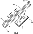
- FIG 3 shows an example of gripping portions 28.
- Each of the gripping portions 28 is provided with mounting means in the form of a base plate 30 for attaching the gripping portion 28 to drive means or to a stationary assembly via mounting holes 32.
- mounting holes 32 it is also conceivable to provide means for a shape-matched or snap-fit connection.
- the gripping portions 28 cooperate to define two channels 26 that are arranged at opposite ends of the gripping portions 28.
- the channels 26 in Figure 3 have a contour that provides shape matching to the cavities 14 of the connector, as will be explained in more detail in reference to Figure 5 .
- Figure 3 illustrates a slight gap between the respective gripping portions 28, the gripping portions 28 can be configured so that opposing surfaces 34 that define the contour of the respective channels 26 abut each other to form a closed channel 26, i.e. a channel 26 having a closed contour.
- Figure 4 shows a further example of gripping portions 28.
- the channels 26 shown in Figure 4 are arranged closer together, for example in order to accommodate the two wires of a twisted pair (see also Figure 6 ).
- the gripping portions 28 have asymmetric outer edges 36, with one edge 36 extending in parallel to the top and bottom edges of the page, while the other edge 36 extends at an angle to form a substantially triangular shape.
- the slanted edge 36 may accommodate previously plugged wires 16 as the guiding device 24 and the base 22 move relative to one another.
- Figure 4 also shows a removable attachment portion 38 that is configured to slide onto the outer edges 36 of the gripping portions 28.
- the attachment portion 38 defines two further apertures 40 that are aligned with and extend in parallel to the channels 26.
- the attachment portion 38 is formed integrally as a monolithic component, for example by injection molding.
- the apertures 40 of the attachment portion 38 cannot automatically release a wire 16 in the same manner as the moveable gripping portions 28.
- the attachment portion 38 may be useful for inserting cavity plugs into cavities 14 that are not configured to receive a wire and terminal. The cavity plugs are inserted through and out the bottom of the aperture 40 so that the plugs do not remain in contact with the attachment portion 38.
- Figure 4 illustrates the channels 26 and the apertures 40 as having the same circular contour, it is also conceivable that the channels 26 and the apertures 40 have different contours.
- Figure 5 shows a partial top view and a cross-section through further gripping portions 28 that define a channel 26 with a shape-matched feature similar to the channels 26 in Figure 3 . While one of the gripping portions 28 has a substantially rectangular indentation when seen in the top view, the other gripping portion 28 has a trapezoidal indentation that matches the rectangular indentation of the other gripping portion 28. Together, the gripping portions 28 define a channel 26 whose outer contour has five sides that correspond roughly to the shape of a connector cavity 14, as shown in Figure 1 . When the ends of a wire 16 are provided with a terminal, such a shape-matching feature helps the user to insert the terminal through the channel 26 and into the cavity 14 with the correct orientation, which prevents damage and assembly error.
- the cross-section in Figure 5 also shows the relationship between the combined thickness T of the gripping portions 28 in relation to the thickness t of the channel 26.
- the illustrated gripping portions have a relatively small thickness ratio t/T of approximately 1.5 to 2.0, which is useful when assembling cable harness connectors 10 with many small cavities 14 that are arranged close to one another. When the thickness ratio t/T is substantially larger, it may be difficult to move through the steps of the connecting sequence while accommodating the wires 16 that have already been plugged into the connector 10.
- Figure 6A shows an embodiment of a system 20 from above, in which the guiding device 24 is connected to a robot arm 42 that forms driving means that move the guiding device 24 relative to the base 22 and the connector 10.
- a robot arm 42 One particular aspect of a robot arm 42 is that it enables the gripping portions 28 of the guiding device 24 to pivot about an axis that is perpendicular to the page. This functionality is useful for accommodating twisted pairs, triple or jacket wires, as is shown schematically in the side view of Figure 6B .
- FIG. 6B The partial cross section of Figure 6B shows both ends of a twisted pair 18 being simultaneously inserted into two adjacent cavities 14 of the connector 10. While the adjacent cavities 14 for some twisted pairs may correspond to the orientation of the channels 26 shown in Figures 6A and 6B , other wires may require adjacent cavities 14 that are arranged at a 90 degree angle to the illustrated orientation of the gripping portions 28. In this case, the robot arm 42 may pivot the entire guiding device 24 about an axis A to orient the channels 26 with the appropriate pair of adjacent cavities 14.
- the cross-sectional view of Figure 6B also schematically illustrates a low height H of the gripping portions 28 that is designed to accommodate the relatively short open or stripped ends of the twisted pair 18.
- a slightly taller set of gripping portions 28 may ensure correct vertical insertion of the wire to prevent bending or defects.
Landscapes
- Engineering & Computer Science (AREA)
- Manufacturing & Machinery (AREA)
- Manufacturing Of Electrical Connectors (AREA)
- Details Of Connecting Devices For Male And Female Coupling (AREA)
Abstract
Description
- The present disclosure relates to an assisted method of electrically connecting a plurality of wires to a connector and to a corresponding assembly system. More specifically, the present disclosure relates to assembly methods and systems for electrically connecting the wires of a cable harness to a connector.
- Cable harnesses, also called wire harnesses, comprise a bundle of wires or cables (hereinafter "wires") used to transmit electrical power or signals and are commonly found in vehicles and machinery. In contrast to individual loose wires, cable harnesses protect wires from outside influences and have advantages in terms of packaging and assembly. As the electronic systems in modern vehicles and machinery become more sophisticated, the volume of information transmitted via cable harnesses has increased, which makes them more complicated to design and assemble.
- Generally speaking, cable harnesses are assembled by cutting a plurality of wires to length, stripping their ends, and fitting the ends of the sires with terminals for connection to connector housings (hereinafter "connector"). The wires are assembled in a bundle on an assembly board according to a predetermined design, and the bundles may be encased in a protective sleeve or covering prior to delivery.
- Though individual steps in the assembly process have been automated, it has been difficult so far to implement an entirely automated process, for example, due to the various different configurations of cable harnesses or the dexterity required to assemble the small parts. For this reason, manual assembly of cable harnesses and particularly the connection of wires and terminals to connectors is common, but is not without its challenges. For instance, the assembly process requires highly skilled workers but is still prone to human error. The nature of the assembly process has also made implementation on a moving assembly line difficult.
- One particularly challenging trend is the miniaturization of the terminals and connectors used for cable harnesses. As components become smaller, the cavity numbers on connectors become more difficult to read, especially when an assembly worker is wearing protection glasses. The wires attached to small terminals are difficult to grasp when wearing gloves, and primary locking detection of the terminals can be difficult to detect, which increases the risk of unseated terminals. These factors increase the time and therefore the cost needed for assembly.
- Given these challenges, there have been proposals to fully automate the cable harness assembly process. However, automated systems are expensive and may be inflexible in terms of production capacity or design changes. The different types of wires used in cable harnesses, for example twisted pair or jacketed wires, have also proven difficult to assemble in automated systems. Therefore, there remains a need for improved methods and systems for electrically connecting wires to connectors.
- The present disclosure provides a method of electrically connecting a plurality of wires to connector that is based on robot or machine-assisted manual assembly. In the method of claim 1, a connector comprising a plurality of cavities is initially secured onto a base. A predetermined connecting sequence is loaded onto the memory of a guiding device that assists the assembly worker (hereinafter "user").
- Each step of the connecting sequence includes the location of one or more cavities of the connector that is configured to receive a wire, for example an end of a wire fitted with a terminal. For the sake of simplicity, the following disclosure refers to the ends of the wire, which also includes the terminals for connecting the wire to the housing. Next, a plurality of wires that each correspond to the respective steps of the connecting sequence are prepared. The connecting sequence is then started to automatically move the guiding device into place. This means that one or more channels defined by the guiding device are aligned with one or more cavities indicated in the first step of the connecting sequence such that the wire end can be guided through each channel and into the aligned cavity.
- After the automatic aligning step, the user manually guides the end of the wire through the channel of the guiding device and into the aligned cavity to electrically connect or plug the wire. If the wire has multiple ends, each of the wire ends is guided through a corresponding channel and into an aligned cavity. In this way, the guiding device indicates the correct cavity for receiving a specific wire end to the user in a clear and simple manner. This reduces the likelihood that the wire end is plugged into the wrong cavity. Furthermore, the channel of the guiding device reduces the likelihood that the wire end or terminal is inserted at an angle that may cause the wire to bend or break. Once the wire has been plugged into the corresponding cavity, the wire is both electrically and mechanically connected to the connector, so the guiding device releases the wire to align the channel with the next cavity defined by the connecting sequence. The automatic aligning step, the manual guiding and connecting step and the automatic release step are repeated in this order until all of the steps of the connecting sequence have been executed.
- The assisted assembly method of the present disclosure combines both manual and automatic assembly steps to improve output and quality while also maintaining the flexibility and lower assembly costs associated with a manual assembly process. Additionally, the method can be easily combined with existing methods to partially automate the cable harness assembly process, for example with systems and machines for automatically cutting wires and/or assembling terminals to the ends of wires.
- Further embodiments and advantages of the assembly method are defined by the dependent claims and described in the following:
- In some cases, the cable harness assembly process may incorporate cavity plugs for sealing cavities that are not configured to receive a wire end or terminal. Accordingly, an embodiment of the method may include the further steps of loading a predetermined plugging sequence on to the controller of the guiding device, with each step of the plugging sequence defining the location of one or more cavities that are not included in the connecting sequence of claim 1. The plugging sequence is automatically started to move the guiding device to align the one or more channels with the one or respective cavities corresponding to the first step of the plugging sequence. The user then manually inserts a cavity plugs through the one or more channels and into the corresponding one or more cavities. The automatic aligning step and the manual plugging step are repeated until all of the steps of the plugging sequence of been executed. At this point, the connecting sequence of the method of claim 1 can then be started. Using an assisted process for inserting cavity plugs eliminates the time necessary to correct the placement of cavity plugs before the wires can be plugged in or connected.
- A further way of reducing process time is to manually guide both ends of a wire comprising a twisted pair through corresponding channels of the guiding device into the respective cavities at the same time. This embodiment is also advantageous over a fully automated assembly system, which may be unable to handle wires having more than one terminal attached to its end.
- According to one embodiment, the releasing step can automatically occur once a specific amount of time has elapsed since the aligning step. This variation can stabilize the cycle times for assembly to reduce overall assembly time. However, the user may also need additional time to complete the manual guiding step, for example during training. In this case, the releasing step may optionally depend from a release signal provided to a controller of the guiding device, for example, by means of a button or a pedal.
- The present disclosure also provides an assisted assembly system that comprises a base, which defines a base plane and is configured to support a connector, and a guiding device that includes first and second moveable gripping portions and an actuator for moving the gripping portions between an open and closed position, for example a servo drive or a pneumatic or hydraulic actuator. The gripping portions are configured to cooperate in the closed position to define one or more channels that extend perpendicularly to the base plane and are configured to receive one or more wire ends for manual insertion into connector cavities, while the actuator opens the gripping portions to release an inserted wire. The assembly system also comprises driving means for moving the base and/or the guiding device relative to each other, with the one or more channels remaining perpendicular to the base plane in order to automatically align the one or more channels with the respective connector cavities corresponding to the aforementioned sequence steps. Finally, the assembly system comprises a controller configured to control the driving means and the actuator of the gripping portions according to a predetermined sequence, for example the aforementioned connecting sequence and the optional plugging sequence.
- The system of the present disclosure provides the necessary guidance and assistance for cable harness connector assembly, but is simple to implement. This reduces assembly error and improves quality over completely manual assembly systems without incurring the high start-up costs of fully automated assembly systems.
- Further embodiments and advantages of the assisted assembly system are defined by the dependent claims and are described below.
- In one embodiment, the driving means are configured to move the base within the base plane. For example, the base can be a motorized tray or board that provides movement within and perpendicular to the base plane, while the guiding device does not change its position relative to the base plane.
- In another embodiment, the driving means may be configured to move the guiding device parallel and/or perpendicular to the base plane, for example, while the base remains stationary. Such arrangements may be perceived as more pleasant to use and provide ergonomic advantages. For example, a robot arm connected to the guiding device may form part of the driving means, as reasonably priced robot arms are available on the market. A robot arm can also be used to pivot the guiding device about an axis perpendicular to the base plane. This movement of the guiding device makes it possible to accommodate different orientations of terminals, in particular for twisted pair, jacketed or triple wires. In addition to a robot arm, other suitable means may be used to pivot the guiding device about an axis.
- In addition to embodiments in which either the base or the guiding device are configured to remove while the other remains stationary, an embodiment in which the driving means are configured to move both the base and the guiding device relative to one another is conceivable. For example, the base may be configured to move within the base plane while the guiding device is configured to pivot about an axis that extends perpendicularly to the base plane.
- In one embodiment, a contour of the one or more channels defined by the gripping portions may include a shape-matching feature that assists the user in the orientation of the wire end, particularly with a terminal attached to the wire end. For example, the channel may have the same contour as the outer contour of the connector cavity. Additionally or alternatively, the gripping portions may comprise opposing surfaces that are configured to abut one another when the gripping portions are closed, which defines one or more closed channels for guiding the end of a wire into a corresponding connector cavity. This feature is particularly advantageous in conjunction with the shape-matched contour of the channel. However, even if there is a minor gap between the opposing surfaces of the gripping portions, the guiding device is still able to assist the user in assembling the connector.
- In another embodiment, the guiding device may include mounting means for mounting the guiding device. The mounting means make it possible to produce a custom-made gripping device and attach it to readily available driving means, such as a robot arm. This embodiment may include any suitable known mounting means, for example a screwed connection, but it may particularly include mounting means that can be operated without tools, such as a shape-matched or snap-fit connection. Mounting means that can be operated without tools make it possible for the user to switch out different guiding devices while keeping the same driving means to provide a simple and relatively inexpensive modular assembly system. Switching out different guiding devices may be made easier if the first and second gripping portions are connected to one another to form a single removable unit. For example, the gripping portions may include a springloaded or biased connection that biases the gripping portions in their closed position, and the actuator acts against the biasing force to open the gripping portions and automatically release the inserted wire(s).
- In one embodiment, the guiding device may include a removable attachment portion that defines one or more apertures that extend in parallel to the channels defined by the gripping portions. Preferably, this attachment portion can be attached to the guiding device without the use of tools, such as by shape-matched or snap-fit connection. The attachment portion may be convenient for plugging cavity plugs into some of the connector cavities before the wires are inserted through the channel(s) of the gripping portions.
- In another embodiment, the gripping portions may be asymmetric about a plane extending perpendicularly to the base plane. Such an asymmetry may be used to form an outer contour of the channel(s) that is shape-matched to the cavity contour or the outer contour of the terminals. However, the asymmetry of the gripping portions may also include one outer edge of the gripping portion that extends in parallel to said plane while the other outer edge is arranged at an angle. The angled outer edge may form a trailing edge that accommodates previously inserted wires as the guiding device moves from one cavity to the next. In any case, the gripping portions may also be symmetric about the aforementioned plane, i.e. formed in mirror image. Such symmetric gripping portions may be simple to manufacture.
- In yet a further embodiment, the system may comprise an input device, e.g. a button or a foot pedal, for sending a release signal to the controller to release an inserted wire from the channel of the guiding device. This embodiment allows the user to determine the speed of the connecting sequence, e.g. during training.
- Further details and advantages of the present method and system will be described in reference to the drawing, in which the same reference numerals are used to indicate similar parts throughout various embodiments.
- Figure 1
- shows an example of a connector or connector housing to which wires can be connected using the method and system of the present disclosure.
- Figure 2A to 2D
- provide a schematic overview of the assisted assembly method of the present disclosure.
- Figures 3 to 5
- provide schematic illustrations of different gripping portions.
- Figure 6
- shows an embodiment of an assisted assembly system that can accommodate twisted pair, triple or jacketed wires.
-
Figure 1 shows an example of aconnector 10 for a cable harness that includes anouter housing 12 and a plurality ofcavities 14 that are configured to receive a cavity plug or a terminal attached to the end of a wire. In some cases, the terminals may be small and delicate and have outer dimensions as small as 0.6 mm. At the same time, the total distance "d" between twoadjacent cavities 14 may be less than 2 mm, which increases eyestrain for the user and increases the likelihood of incorrectly plugged terminals and cavity plugs. -
Figure 2 shows a schematic overview of a method and asystem 20 for assisted plugging or connection ofwires 16 that reduces plugging error. For the sake of simplicity, thewires 16 in the drawing have been shown without terminals crimped to their ends. However, the method and system of the present disclosure are applicable to wires that include terminals. Aconnector 10 rests on a base 22 that defines a horizontal base plane B. ThoughFigure 2 shows thebase 22 and the base plane B extending substantially horizontally, they may also be oriented at an angle depending on the configuration of a particular workspace. A partial cross-section through thehousing 12 shows a plurality ofcavities 14 that are arranged next to one another. - The
system 20 also includes a guidingdevice 24 that is arranged vertically above theconnector 10 and includes achannel 26 that is aligned with one of thecavities 14 of theconnector 10, as indicated by the dashed line inFigure 2A . Thechannel 26 is defined by a pair ofgripping portions 28 that are configured to cooperate with one another.Figures 2A to 2D each show a cross-section through the grippingportions 28. - In
Figure 2A , theleftmost cavity 14 of the connector corresponds to a first cavity of a pre-loaded connecting sequence, and the position of the guidingdevice 24 corresponds to the start of the automatic connecting sequence.Figure 2B shows the next step of the connecting process in which the end of awire 16 is inserted by hand (not shown) through thechannel 26 and into the correspondingcavity 14. Once thewire 16 has been inserted into thecavity 14 and electrically connected to theconnector 10, the grippingportions 28 of the guidingdevice 24 enclose thewire 16 in the same way as a bead threaded onto a string (Figure 2B ). In order to release thewire 16, the movement arrows inFigure 2C show thegripping portions 28 moving apart from one another as moved by an actuator (not illustrated) to automatically release thewire 16 from thechannel 26. The actuator for the guidingdevice 24 may be a servo drive, but pneumatic or hydraulic actuators can also be used. Generally speaking, the actuator may be configured to open thegripping portions 28 after a certain amount of time has elapsed. However, it is also possible for the actuator to be configured to open thegripping portions 28 in response to a release signal provided by the user via a controller of the system. The release signal may be generated when the user pushes a button or activates a pedal (not shown). - After opening to release the first wire 16 (
Figure 2C ), the grippingportions 28 move in a direction perpendicular to the page and are closed again. The grippingportions 28 may be closed again by the actuator, but alternatively the grippingportions 28 could include connecting means that bias the grippingportions 28 in a closed position. The actuator could then be activated to counteract the biasing force long enough for thegripping portions 28 to release the insertedwire 16, whereupon the biasing force returns the grippingportions 28 to their closed position. - The
channel 26 is then aligned with afurther cavity 14 so that asubsequent wire 16 can be inserted into the cavity 14 (Figure 2D). Figure 2D shows two movement arrows that indicate relative movement between the base 22 and the guidingdevice 24 to align thechannel 26 with the next cavity. Generally speaking, thebase 22 may move relative to the guidingdevice 24 or vice versa, or both thebase 22 and the guidingdevice 24 may be configured for relative movement. In any case, the controller of thesystem 20 controls driving means for thebase 22 and/or the guidingdevice 24 together with the actuator for thegripping portions 28 to sequentially move along a series ofcavities 14 to ensure that the user inserts wires into thecorrect cavities 14. -
Figure 3 shows an example of grippingportions 28. Each of thegripping portions 28 is provided with mounting means in the form of abase plate 30 for attaching the grippingportion 28 to drive means or to a stationary assembly via mountingholes 32. As an alternative to mountingholes 32, it is also conceivable to provide means for a shape-matched or snap-fit connection. The grippingportions 28 cooperate to define twochannels 26 that are arranged at opposite ends of thegripping portions 28. Thechannels 26 inFigure 3 have a contour that provides shape matching to thecavities 14 of the connector, as will be explained in more detail in reference toFigure 5 . ThoughFigure 3 illustrates a slight gap between the respectivegripping portions 28, the grippingportions 28 can be configured so that opposingsurfaces 34 that define the contour of therespective channels 26 abut each other to form aclosed channel 26, i.e. achannel 26 having a closed contour. -
Figure 4 shows a further example of grippingportions 28. Unlike the twochannels 26 shown inFigure 3 , thechannels 26 shown inFigure 4 are arranged closer together, for example in order to accommodate the two wires of a twisted pair (see alsoFigure 6 ). Furthermore, the grippingportions 28 have asymmetricouter edges 36, with oneedge 36 extending in parallel to the top and bottom edges of the page, while theother edge 36 extends at an angle to form a substantially triangular shape. When thegripping portions 28 shown inFigure 4 are mounted to a guidingdevice 24, the slantededge 36 may accommodate previously pluggedwires 16 as the guidingdevice 24 and the base 22 move relative to one another. -
Figure 4 also shows aremovable attachment portion 38 that is configured to slide onto theouter edges 36 of thegripping portions 28. Theattachment portion 38 defines twofurther apertures 40 that are aligned with and extend in parallel to thechannels 26. Theattachment portion 38 is formed integrally as a monolithic component, for example by injection molding. In other words, theapertures 40 of theattachment portion 38 cannot automatically release awire 16 in the same manner as the moveablegripping portions 28. However, theattachment portion 38 may be useful for inserting cavity plugs intocavities 14 that are not configured to receive a wire and terminal. The cavity plugs are inserted through and out the bottom of theaperture 40 so that the plugs do not remain in contact with theattachment portion 38. ThoughFigure 4 illustrates thechannels 26 and theapertures 40 as having the same circular contour, it is also conceivable that thechannels 26 and theapertures 40 have different contours. -
Figure 5 shows a partial top view and a cross-section through further grippingportions 28 that define achannel 26 with a shape-matched feature similar to thechannels 26 inFigure 3 . While one of thegripping portions 28 has a substantially rectangular indentation when seen in the top view, the other grippingportion 28 has a trapezoidal indentation that matches the rectangular indentation of the other grippingportion 28. Together, the grippingportions 28 define achannel 26 whose outer contour has five sides that correspond roughly to the shape of aconnector cavity 14, as shown inFigure 1 . When the ends of awire 16 are provided with a terminal, such a shape-matching feature helps the user to insert the terminal through thechannel 26 and into thecavity 14 with the correct orientation, which prevents damage and assembly error. - The cross-section in
Figure 5 also shows the relationship between the combined thickness T of thegripping portions 28 in relation to the thickness t of thechannel 26. The illustrated gripping portions have a relatively small thickness ratio t/T of approximately 1.5 to 2.0, which is useful when assemblingcable harness connectors 10 with manysmall cavities 14 that are arranged close to one another. When the thickness ratio t/T is substantially larger, it may be difficult to move through the steps of the connecting sequence while accommodating thewires 16 that have already been plugged into theconnector 10. -
Figure 6A shows an embodiment of asystem 20 from above, in which the guidingdevice 24 is connected to arobot arm 42 that forms driving means that move the guidingdevice 24 relative to thebase 22 and theconnector 10. One particular aspect of arobot arm 42 is that it enables thegripping portions 28 of the guidingdevice 24 to pivot about an axis that is perpendicular to the page. This functionality is useful for accommodating twisted pairs, triple or jacket wires, as is shown schematically in the side view ofFigure 6B . - The partial cross section of
Figure 6B shows both ends of atwisted pair 18 being simultaneously inserted into twoadjacent cavities 14 of theconnector 10. While theadjacent cavities 14 for some twisted pairs may correspond to the orientation of thechannels 26 shown inFigures 6A and6B , other wires may requireadjacent cavities 14 that are arranged at a 90 degree angle to the illustrated orientation of thegripping portions 28. In this case, therobot arm 42 may pivot theentire guiding device 24 about an axis A to orient thechannels 26 with the appropriate pair ofadjacent cavities 14. - The cross-sectional view of
Figure 6B also schematically illustrates a low height H of thegripping portions 28 that is designed to accommodate the relatively short open or stripped ends of the twistedpair 18. However, for other applications, it is imaginable that a slightly taller set of grippingportions 28 may ensure correct vertical insertion of the wire to prevent bending or defects. In other words, it may be advantageous to providemultiple guiding devices 24 having different heights H or thicknesses T that are better suited to specific assembly applications. - While the previous disclosure describes an assisted
system 20 and assembly method in the specific context of cable harnesses, the disclosure is not limited to such applications and may also prove advantageous in other applications that require the electrical connection of wires or cables to a connector or connector housing. -
- 10
- connector
- 12
- outer housing
- 14
- connector cavity
- 16
- wire
- 18
- twisted pair
- 20
- system
- 22
- base
- 24
- guiding device
- 26
- channel
- 28
- gripping portion
- 30
- base plate
- 32
- mounting hole
- 34
- opposing surface
- 36
- outer edge
- 38
- attachment portion
- 40
- aperture
- 42
- robot arm
- A
- rotational axis
- B
- base plane
Claims (15)
- An assisted method of electrically connecting a plurality of wires (16, 18) to a connector (10), comprising the steps of:securing the connector (10) comprising a plurality of cavities (14) onto a base (22);loading a predetermined connecting sequence onto the controller of a guiding device (24), wherein each step of the connecting sequence includes the location of one or more of the cavities (14);preparing a plurality of wires (16, 18) that each correspond to the respective steps of the connecting sequence;starting the connecting sequence to automatically move the guiding device (24) to align one or more channels (26) with the respective one or more cavities (14) that correspond to the first step of the connecting sequence; andrepeating the following steps until the end of the connecting sequence:manually guiding each of the one or more ends of the wire (16, 18) corresponding to the connecting sequence through the corresponding channel (26) of the guiding device (24) and into the aligned cavity (14) to electrically connect the wire (16, 18) to the connector (10);releasing the wire (16, 18) from the guiding system (24); andautomatically aligning the one or more channels (26) of the guiding device with the one or more cavities (14) corresponding to the next step of the connecting sequence.
- The method of claim 1, further comprising the steps of:loading a predetermined plugging sequence onto the controller of the guiding device (24), wherein each step of the plugging sequence includes the location of one or more cavities (14) that are not included in the connecting sequence;starting the plugging sequence to automatically move the guiding device (24) to align the one or more channels (26) with one or more respective cavities (14) corresponding to the first step of the plugging sequence;manually inserting a cavity plug through the one or more channels (26) and into the corresponding one or more cavities (14); andexecuting the remaining steps of the plugging sequence while manually inserting one or more cavity plugs for each sequence step,wherein the plugging sequence is executed before the connecting sequence is started.
- The method of claim 1 or claim 2, wherein the two ends of a wire (18) comprising a twisted pair are manually guided through corresponding channels (26) of the guiding device (24) and into their respective cavities at the same time to electrically connect the wire (18) to the connector (10).
- The method of any of claims 1 to 3, wherein the guided wire (16, 18) is released when the controller of the guiding device (24) receives a release signal.
- An assisted assembly system comprising:a base (22) that defines a base plane (B) and is configured to support a connector (10);a guiding device (24) having first and second moveable gripping portions (28) and an actuator for moving the gripping portions (28), wherein the gripping portions (28) cooperate to define one or more channels (26) that extend perpendicularly to the base plane (B) and are configured to receive one or more wire ends for manual insertion;driving means for moving the base (22) and/or the guiding device (24) relative to each other, with the one or more channels (26) remaining perpendicular to the base plane (B); anda controller configured to control the driving means and the actuator of the gripping portions (28) according to a predetermined sequence.
- The system of claim 5, wherein the driving means are configured to move the base (22) within the base plane (B).
- The system of claim 5 or 6, wherein the driving means are configured to move the guiding device (24) parallel and/or perpendicular to the base plane (B), in particular wherein the driving means include a robot arm (42) connected to the guiding device (24).
- The system of claim 7, wherein the driving means are configured to pivot the first and second gripping portions (28) about an axis (A) perpendicular to the base plane (B).
- The system of any of claims 5 to 8, wherein a contour of the one or more channels (26) defined by the gripping portions (28) includes a shape-matching feature.
- The system of any of claims 5 to 9, wherein surfaces (34) of the gripping portions (28) are configured to abut one another when the gripping portions (28) are closed to define one or more closed channels (26).
- The system of any of claims 5 to 10, wherein the guiding device (24) includes mounting means (30) for mounting the guiding device (24).
- The system of any of claims 5 to 11, wherein the gripping portions (28) are connected to one another.
- The system of any of claims 5 to 12, wherein the guiding device (24) further includes a removable attachment portion (38) that defines one or more apertures (40) that extend in parallel to the one or more channels (26) defined by the gripping portions (28).
- The system of any of claims 5 to 13, wherein the first and second gripping portions (28) are asymmetric about a plane extending perpendicularly to the base plane (B), in particular wherein an outer edge (36) of the first gripping portion (28) or the second gripping portion (28) extends at an angle to said plane.
- The system of any of claims 5 to 14, further comprising an input device for sending a release signal to the controller, which is configured to send a corresponding release signal to the actuator of the guiding device.
Priority Applications (3)
| Application Number | Priority Date | Filing Date | Title |
|---|---|---|---|
| EP18154741.5A EP3522311B1 (en) | 2018-02-01 | 2018-02-01 | Assisted assembly method and system |
| US16/249,206 US11239622B2 (en) | 2018-02-01 | 2019-01-16 | System for connecting wires of an electrical cable harness to an electrical connector |
| CN201910095471.8A CN110112632B (en) | 2018-02-01 | 2019-01-31 | Auxiliary assembly method and system |
Applications Claiming Priority (1)
| Application Number | Priority Date | Filing Date | Title |
|---|---|---|---|
| EP18154741.5A EP3522311B1 (en) | 2018-02-01 | 2018-02-01 | Assisted assembly method and system |
Publications (2)
| Publication Number | Publication Date |
|---|---|
| EP3522311A1 true EP3522311A1 (en) | 2019-08-07 |
| EP3522311B1 EP3522311B1 (en) | 2021-05-19 |
Family
ID=61132330
Family Applications (1)
| Application Number | Title | Priority Date | Filing Date |
|---|---|---|---|
| EP18154741.5A Active EP3522311B1 (en) | 2018-02-01 | 2018-02-01 | Assisted assembly method and system |
Country Status (3)
| Country | Link |
|---|---|
| US (1) | US11239622B2 (en) |
| EP (1) | EP3522311B1 (en) |
| CN (1) | CN110112632B (en) |
Families Citing this family (3)
| Publication number | Priority date | Publication date | Assignee | Title |
|---|---|---|---|---|
| CN111113004A (en) * | 2019-11-19 | 2020-05-08 | 蚌埠兴创电子科技有限公司 | Sensor base that facilitates use is with dress lead machine |
| EP3872513B8 (en) * | 2020-02-27 | 2024-05-01 | Aptiv Technologies AG | Wire harness test device and method for verifying connections when assembling a wire harness |
| CN113675702B (en) * | 2021-07-13 | 2024-02-20 | 北京无线电测量研究所 | Plug mechanism |
Citations (2)
| Publication number | Priority date | Publication date | Assignee | Title |
|---|---|---|---|---|
| JPH09167670A (en) * | 1995-12-18 | 1997-06-24 | Sumitomo Wiring Syst Ltd | Terminal insertion support method and device |
| WO2017038804A1 (en) * | 2015-09-04 | 2017-03-09 | 矢崎総業株式会社 | Terminal insertion guidance device, wire harness manufacturing jig, and terminal insertion method |
Family Cites Families (17)
| Publication number | Priority date | Publication date | Assignee | Title |
|---|---|---|---|---|
| US2998633A (en) * | 1955-10-14 | 1961-09-05 | Artos Engineering Co | Wire cutting, stripping and terminal attaching machine |
| US4156961A (en) * | 1978-05-17 | 1979-06-05 | Shin Meiwa Industry Co., Ltd. | Wire collecting apparatus for use with wire cutting and insulation stripping machine |
| GB8412827D0 (en) * | 1984-05-18 | 1984-06-27 | Molex Inc | Terminated wires into electrical connectors |
| US7257878B2 (en) * | 1995-11-06 | 2007-08-21 | Beat Locher | Continuous cable processing apparatus |
| DE59914354D1 (en) * | 1998-08-31 | 2007-07-12 | Komax Holding Ag | Device for merging ladders |
| MXPA01003356A (en) * | 2000-04-10 | 2004-07-30 | Sumitomo Wiring Systems | Terminal crimping device. |
| JP2004185852A (en) * | 2002-11-29 | 2004-07-02 | Sumitomo Wiring Syst Ltd | Method for manufacturing wire harness, and connecting device of electric wire with terminal |
| EP1515403B1 (en) * | 2003-09-10 | 2007-10-24 | komax Holding AG | Cable processing apparatus |
| JP4351603B2 (en) * | 2004-09-28 | 2009-10-28 | 矢崎総業株式会社 | Terminal insertion device |
| ITPD20050297A1 (en) * | 2005-10-12 | 2007-04-13 | K M I Trade Srl | EQUIPMENT FOR THE REALIZATION OF ELECTRICAL WIRES |
| US7774927B2 (en) * | 2007-07-27 | 2010-08-17 | Tyco Electronics Corporation | Wire positioning device for a wire termination machine |
| EP2317613B1 (en) * | 2009-10-28 | 2015-08-12 | Komax Holding AG | Device and method for handling the ends of cables |
| US9317023B2 (en) * | 2012-09-20 | 2016-04-19 | Tyco Electronics Corporation | Wire sorting machine and method of sorting wires |
| US9787046B2 (en) * | 2012-10-22 | 2017-10-10 | Te Connectivity Corporation | Wire sorting fixture and method of sorting wires |
| US8979155B2 (en) * | 2013-03-22 | 2015-03-17 | Mpi Incorporated | Apparatus, system, and process for the automated retrieval and precise placement of small rods |
| US9720185B2 (en) * | 2014-05-23 | 2017-08-01 | Commscope Technologies Llc | Systems and method for processing optical cable assemblies |
| US10826259B2 (en) * | 2018-05-15 | 2020-11-03 | Cheng Uei Precision Industry Co., Ltd. | Automatic wire arranging device |
-
2018
- 2018-02-01 EP EP18154741.5A patent/EP3522311B1/en active Active
-
2019
- 2019-01-16 US US16/249,206 patent/US11239622B2/en active Active
- 2019-01-31 CN CN201910095471.8A patent/CN110112632B/en active Active
Patent Citations (2)
| Publication number | Priority date | Publication date | Assignee | Title |
|---|---|---|---|---|
| JPH09167670A (en) * | 1995-12-18 | 1997-06-24 | Sumitomo Wiring Syst Ltd | Terminal insertion support method and device |
| WO2017038804A1 (en) * | 2015-09-04 | 2017-03-09 | 矢崎総業株式会社 | Terminal insertion guidance device, wire harness manufacturing jig, and terminal insertion method |
Also Published As
| Publication number | Publication date |
|---|---|
| US20190237927A1 (en) | 2019-08-01 |
| CN110112632A (en) | 2019-08-09 |
| US11239622B2 (en) | 2022-02-01 |
| CN110112632B (en) | 2021-02-09 |
| EP3522311B1 (en) | 2021-05-19 |
Similar Documents
| Publication | Publication Date | Title |
|---|---|---|
| EP3522311B1 (en) | Assisted assembly method and system | |
| KR102073527B1 (en) | Electrical connector assembly with axial connection assist | |
| US6238104B1 (en) | Fiber optic connector, supporting member used therein, and method of connecting the fiber optic connector to a fiber optic cable | |
| US5915990A (en) | Plug-in electrical connector including slide conductor fastener means | |
| US5945635A (en) | Wire assembly apparatus and method for assembling wires | |
| KR101753018B1 (en) | Production device for wire harness and production method therefor | |
| JP3551773B2 (en) | Connector holder | |
| US4797112A (en) | Wire holders and harnesses incorporating wire holders | |
| CN111315543A (en) | Method for electrical wiring of electronic components in switchgear construction using cable sequences and corresponding robot arrangement | |
| JP6044533B2 (en) | Terminal insertion apparatus and wiring module manufacturing method | |
| US7266877B2 (en) | Tooling for manufacturing large-section rigid harnesses | |
| EP1088370A1 (en) | Pressure welding connection type connector and pressure welding method therefor | |
| EP1115191B1 (en) | Connection assembly particularly for the windings of a stator of an electric motor | |
| EP3576227B1 (en) | Connector and connector housing | |
| JP4905256B2 (en) | Stator manufacturing method | |
| JP7460347B2 (en) | Joint box, unit cable for indoor wiring, and method for manufacturing unit cable for indoor wiring | |
| JP4275207B2 (en) | Industrial robots and split connectors | |
| CN114503373A (en) | Joint connector | |
| US11320121B2 (en) | Method for assembling an adjustable automotive luminous device | |
| KR100783849B1 (en) | Device for electric connection | |
| EP3604035A1 (en) | Electronic connection assembly, automotive lighting device and method for manufacturing an automotive lighting device | |
| JP5193008B2 (en) | Harness connecting member assembly tool | |
| JP2916630B2 (en) | Power distribution unit | |
| JPH04328211A (en) | Flat cable its manufacture and mounting method | |
| JP6951581B2 (en) | How to manufacture connector holders, terminal insertion devices, and wire harnesses |
Legal Events
| Date | Code | Title | Description |
|---|---|---|---|
| PUAI | Public reference made under article 153(3) epc to a published international application that has entered the european phase |
Free format text: ORIGINAL CODE: 0009012 |
|
| STAA | Information on the status of an ep patent application or granted ep patent |
Free format text: STATUS: THE APPLICATION HAS BEEN PUBLISHED |
|
| AK | Designated contracting states |
Kind code of ref document: A1 Designated state(s): AL AT BE BG CH CY CZ DE DK EE ES FI FR GB GR HR HU IE IS IT LI LT LU LV MC MK MT NL NO PL PT RO RS SE SI SK SM TR |
|
| AX | Request for extension of the european patent |
Extension state: BA ME |
|
| STAA | Information on the status of an ep patent application or granted ep patent |
Free format text: STATUS: REQUEST FOR EXAMINATION WAS MADE |
|
| 17P | Request for examination filed |
Effective date: 20200206 |
|
| RBV | Designated contracting states (corrected) |
Designated state(s): AL AT BE BG CH CY CZ DE DK EE ES FI FR GB GR HR HU IE IS IT LI LT LU LV MC MK MT NL NO PL PT RO RS SE SI SK SM TR |
|
| GRAP | Despatch of communication of intention to grant a patent |
Free format text: ORIGINAL CODE: EPIDOSNIGR1 |
|
| STAA | Information on the status of an ep patent application or granted ep patent |
Free format text: STATUS: GRANT OF PATENT IS INTENDED |
|
| RIC1 | Information provided on ipc code assigned before grant |
Ipc: H01R 43/20 20060101AFI20201102BHEP Ipc: H01R 43/28 20060101ALI20201102BHEP Ipc: H01R 13/52 20060101ALI20201102BHEP Ipc: H01R 43/052 20060101ALN20201102BHEP Ipc: H01R 43/00 20060101ALI20201102BHEP Ipc: H01R 43/055 20060101ALN20201102BHEP |
|
| RIC1 | Information provided on ipc code assigned before grant |
Ipc: H01R 43/052 20060101ALN20201106BHEP Ipc: H01R 43/20 20060101AFI20201106BHEP Ipc: H01R 43/055 20060101ALN20201106BHEP Ipc: H01R 43/00 20060101ALI20201106BHEP Ipc: H01R 43/28 20060101ALI20201106BHEP Ipc: H01R 13/52 20060101ALI20201106BHEP |
|
| RIC1 | Information provided on ipc code assigned before grant |
Ipc: H01R 13/52 20060101ALI20201118BHEP Ipc: H01R 43/20 20060101AFI20201118BHEP Ipc: H01R 43/055 20060101ALN20201118BHEP Ipc: H01R 43/00 20060101ALI20201118BHEP Ipc: H01R 43/28 20060101ALI20201118BHEP Ipc: H01R 43/052 20060101ALN20201118BHEP |
|
| INTG | Intention to grant announced |
Effective date: 20201204 |
|
| GRAS | Grant fee paid |
Free format text: ORIGINAL CODE: EPIDOSNIGR3 |
|
| GRAA | (expected) grant |
Free format text: ORIGINAL CODE: 0009210 |
|
| STAA | Information on the status of an ep patent application or granted ep patent |
Free format text: STATUS: THE PATENT HAS BEEN GRANTED |
|
| AK | Designated contracting states |
Kind code of ref document: B1 Designated state(s): AL AT BE BG CH CY CZ DE DK EE ES FI FR GB GR HR HU IE IS IT LI LT LU LV MC MK MT NL NO PL PT RO RS SE SI SK SM TR |
|
| REG | Reference to a national code |
Ref country code: GB Ref legal event code: FG4D |
|
| REG | Reference to a national code |
Ref country code: CH Ref legal event code: EP |
|
| REG | Reference to a national code |
Ref country code: DE Ref legal event code: R096 Ref document number: 602018017145 Country of ref document: DE |
|
| REG | Reference to a national code |
Ref country code: AT Ref legal event code: REF Ref document number: 1394907 Country of ref document: AT Kind code of ref document: T Effective date: 20210615 |
|
| REG | Reference to a national code |
Ref country code: IE Ref legal event code: FG4D |
|
| REG | Reference to a national code |
Ref country code: LT Ref legal event code: MG9D |
|
| REG | Reference to a national code |
Ref country code: AT Ref legal event code: MK05 Ref document number: 1394907 Country of ref document: AT Kind code of ref document: T Effective date: 20210519 |
|
| REG | Reference to a national code |
Ref country code: NL Ref legal event code: MP Effective date: 20210519 |
|
| PG25 | Lapsed in a contracting state [announced via postgrant information from national office to epo] |
Ref country code: FI Free format text: LAPSE BECAUSE OF FAILURE TO SUBMIT A TRANSLATION OF THE DESCRIPTION OR TO PAY THE FEE WITHIN THE PRESCRIBED TIME-LIMIT Effective date: 20210519 Ref country code: LT Free format text: LAPSE BECAUSE OF FAILURE TO SUBMIT A TRANSLATION OF THE DESCRIPTION OR TO PAY THE FEE WITHIN THE PRESCRIBED TIME-LIMIT Effective date: 20210519 Ref country code: HR Free format text: LAPSE BECAUSE OF FAILURE TO SUBMIT A TRANSLATION OF THE DESCRIPTION OR TO PAY THE FEE WITHIN THE PRESCRIBED TIME-LIMIT Effective date: 20210519 Ref country code: AT Free format text: LAPSE BECAUSE OF FAILURE TO SUBMIT A TRANSLATION OF THE DESCRIPTION OR TO PAY THE FEE WITHIN THE PRESCRIBED TIME-LIMIT Effective date: 20210519 Ref country code: BG Free format text: LAPSE BECAUSE OF FAILURE TO SUBMIT A TRANSLATION OF THE DESCRIPTION OR TO PAY THE FEE WITHIN THE PRESCRIBED TIME-LIMIT Effective date: 20210819 |
|
| PG25 | Lapsed in a contracting state [announced via postgrant information from national office to epo] |
Ref country code: GR Free format text: LAPSE BECAUSE OF FAILURE TO SUBMIT A TRANSLATION OF THE DESCRIPTION OR TO PAY THE FEE WITHIN THE PRESCRIBED TIME-LIMIT Effective date: 20210820 Ref country code: IS Free format text: LAPSE BECAUSE OF FAILURE TO SUBMIT A TRANSLATION OF THE DESCRIPTION OR TO PAY THE FEE WITHIN THE PRESCRIBED TIME-LIMIT Effective date: 20210919 Ref country code: PL Free format text: LAPSE BECAUSE OF FAILURE TO SUBMIT A TRANSLATION OF THE DESCRIPTION OR TO PAY THE FEE WITHIN THE PRESCRIBED TIME-LIMIT Effective date: 20210519 Ref country code: LV Free format text: LAPSE BECAUSE OF FAILURE TO SUBMIT A TRANSLATION OF THE DESCRIPTION OR TO PAY THE FEE WITHIN THE PRESCRIBED TIME-LIMIT Effective date: 20210519 Ref country code: NO Free format text: LAPSE BECAUSE OF FAILURE TO SUBMIT A TRANSLATION OF THE DESCRIPTION OR TO PAY THE FEE WITHIN THE PRESCRIBED TIME-LIMIT Effective date: 20210819 Ref country code: PT Free format text: LAPSE BECAUSE OF FAILURE TO SUBMIT A TRANSLATION OF THE DESCRIPTION OR TO PAY THE FEE WITHIN THE PRESCRIBED TIME-LIMIT Effective date: 20210920 Ref country code: RS Free format text: LAPSE BECAUSE OF FAILURE TO SUBMIT A TRANSLATION OF THE DESCRIPTION OR TO PAY THE FEE WITHIN THE PRESCRIBED TIME-LIMIT Effective date: 20210519 Ref country code: SE Free format text: LAPSE BECAUSE OF FAILURE TO SUBMIT A TRANSLATION OF THE DESCRIPTION OR TO PAY THE FEE WITHIN THE PRESCRIBED TIME-LIMIT Effective date: 20210519 |
|
| PG25 | Lapsed in a contracting state [announced via postgrant information from national office to epo] |
Ref country code: NL Free format text: LAPSE BECAUSE OF FAILURE TO SUBMIT A TRANSLATION OF THE DESCRIPTION OR TO PAY THE FEE WITHIN THE PRESCRIBED TIME-LIMIT Effective date: 20210519 |
|
| PG25 | Lapsed in a contracting state [announced via postgrant information from national office to epo] |
Ref country code: RO Free format text: LAPSE BECAUSE OF FAILURE TO SUBMIT A TRANSLATION OF THE DESCRIPTION OR TO PAY THE FEE WITHIN THE PRESCRIBED TIME-LIMIT Effective date: 20210519 Ref country code: DK Free format text: LAPSE BECAUSE OF FAILURE TO SUBMIT A TRANSLATION OF THE DESCRIPTION OR TO PAY THE FEE WITHIN THE PRESCRIBED TIME-LIMIT Effective date: 20210519 Ref country code: CZ Free format text: LAPSE BECAUSE OF FAILURE TO SUBMIT A TRANSLATION OF THE DESCRIPTION OR TO PAY THE FEE WITHIN THE PRESCRIBED TIME-LIMIT Effective date: 20210519 Ref country code: ES Free format text: LAPSE BECAUSE OF FAILURE TO SUBMIT A TRANSLATION OF THE DESCRIPTION OR TO PAY THE FEE WITHIN THE PRESCRIBED TIME-LIMIT Effective date: 20210519 Ref country code: EE Free format text: LAPSE BECAUSE OF FAILURE TO SUBMIT A TRANSLATION OF THE DESCRIPTION OR TO PAY THE FEE WITHIN THE PRESCRIBED TIME-LIMIT Effective date: 20210519 Ref country code: SM Free format text: LAPSE BECAUSE OF FAILURE TO SUBMIT A TRANSLATION OF THE DESCRIPTION OR TO PAY THE FEE WITHIN THE PRESCRIBED TIME-LIMIT Effective date: 20210519 Ref country code: SK Free format text: LAPSE BECAUSE OF FAILURE TO SUBMIT A TRANSLATION OF THE DESCRIPTION OR TO PAY THE FEE WITHIN THE PRESCRIBED TIME-LIMIT Effective date: 20210519 |
|
| REG | Reference to a national code |
Ref country code: DE Ref legal event code: R097 Ref document number: 602018017145 Country of ref document: DE |
|
| PLBE | No opposition filed within time limit |
Free format text: ORIGINAL CODE: 0009261 |
|
| STAA | Information on the status of an ep patent application or granted ep patent |
Free format text: STATUS: NO OPPOSITION FILED WITHIN TIME LIMIT |
|
| 26N | No opposition filed |
Effective date: 20220222 |
|
| PG25 | Lapsed in a contracting state [announced via postgrant information from national office to epo] |
Ref country code: IS Free format text: LAPSE BECAUSE OF FAILURE TO SUBMIT A TRANSLATION OF THE DESCRIPTION OR TO PAY THE FEE WITHIN THE PRESCRIBED TIME-LIMIT Effective date: 20210919 Ref country code: AL Free format text: LAPSE BECAUSE OF FAILURE TO SUBMIT A TRANSLATION OF THE DESCRIPTION OR TO PAY THE FEE WITHIN THE PRESCRIBED TIME-LIMIT Effective date: 20210519 |
|
| PG25 | Lapsed in a contracting state [announced via postgrant information from national office to epo] |
Ref country code: IT Free format text: LAPSE BECAUSE OF FAILURE TO SUBMIT A TRANSLATION OF THE DESCRIPTION OR TO PAY THE FEE WITHIN THE PRESCRIBED TIME-LIMIT Effective date: 20210519 |
|
| PG25 | Lapsed in a contracting state [announced via postgrant information from national office to epo] |
Ref country code: MC Free format text: LAPSE BECAUSE OF FAILURE TO SUBMIT A TRANSLATION OF THE DESCRIPTION OR TO PAY THE FEE WITHIN THE PRESCRIBED TIME-LIMIT Effective date: 20210519 |
|
| REG | Reference to a national code |
Ref country code: CH Ref legal event code: PL |
|
| REG | Reference to a national code |
Ref country code: BE Ref legal event code: MM Effective date: 20220228 |
|
| PG25 | Lapsed in a contracting state [announced via postgrant information from national office to epo] |
Ref country code: LU Free format text: LAPSE BECAUSE OF NON-PAYMENT OF DUE FEES Effective date: 20220201 |
|
| PG25 | Lapsed in a contracting state [announced via postgrant information from national office to epo] |
Ref country code: LI Free format text: LAPSE BECAUSE OF NON-PAYMENT OF DUE FEES Effective date: 20220228 Ref country code: IE Free format text: LAPSE BECAUSE OF NON-PAYMENT OF DUE FEES Effective date: 20220201 Ref country code: CH Free format text: LAPSE BECAUSE OF NON-PAYMENT OF DUE FEES Effective date: 20220228 |
|
| PG25 | Lapsed in a contracting state [announced via postgrant information from national office to epo] |
Ref country code: BE Free format text: LAPSE BECAUSE OF NON-PAYMENT OF DUE FEES Effective date: 20220228 |
|
| PGFP | Annual fee paid to national office [announced via postgrant information from national office to epo] |
Ref country code: FR Payment date: 20230223 Year of fee payment: 6 |
|
| PGFP | Annual fee paid to national office [announced via postgrant information from national office to epo] |
Ref country code: GB Payment date: 20230216 Year of fee payment: 6 Ref country code: DE Payment date: 20230127 Year of fee payment: 6 |
|
| P01 | Opt-out of the competence of the unified patent court (upc) registered |
Effective date: 20230420 |
|
| PG25 | Lapsed in a contracting state [announced via postgrant information from national office to epo] |
Ref country code: MK Free format text: LAPSE BECAUSE OF FAILURE TO SUBMIT A TRANSLATION OF THE DESCRIPTION OR TO PAY THE FEE WITHIN THE PRESCRIBED TIME-LIMIT Effective date: 20210519 Ref country code: CY Free format text: LAPSE BECAUSE OF FAILURE TO SUBMIT A TRANSLATION OF THE DESCRIPTION OR TO PAY THE FEE WITHIN THE PRESCRIBED TIME-LIMIT Effective date: 20210519 |