EP3522291A1 - Rohranordnung für ein flüssigkeitsverteilungssystem eines batteriepacks eines fahrzeugs und batteriepack für ein fahrzeug - Google Patents
Rohranordnung für ein flüssigkeitsverteilungssystem eines batteriepacks eines fahrzeugs und batteriepack für ein fahrzeug Download PDFInfo
- Publication number
- EP3522291A1 EP3522291A1 EP18154418.0A EP18154418A EP3522291A1 EP 3522291 A1 EP3522291 A1 EP 3522291A1 EP 18154418 A EP18154418 A EP 18154418A EP 3522291 A1 EP3522291 A1 EP 3522291A1
- Authority
- EP
- European Patent Office
- Prior art keywords
- tube
- connector
- connector tube
- tube assembly
- locking ring
- Prior art date
- Legal status (The legal status is an assumption and is not a legal conclusion. Google has not performed a legal analysis and makes no representation as to the accuracy of the status listed.)
- Granted
Links
- 239000012530 fluid Substances 0.000 title claims abstract description 18
- 238000007789 sealing Methods 0.000 description 12
- 210000001699 lower leg Anatomy 0.000 description 5
- 238000007599 discharging Methods 0.000 description 4
- 238000007373 indentation Methods 0.000 description 4
- 238000006243 chemical reaction Methods 0.000 description 2
- 230000000295 complement effect Effects 0.000 description 2
- 238000001816 cooling Methods 0.000 description 2
- 239000012809 cooling fluid Substances 0.000 description 2
- 239000008151 electrolyte solution Substances 0.000 description 2
- 238000000034 method Methods 0.000 description 2
- WHXSMMKQMYFTQS-UHFFFAOYSA-N Lithium Chemical compound [Li] WHXSMMKQMYFTQS-UHFFFAOYSA-N 0.000 description 1
- HBBGRARXTFLTSG-UHFFFAOYSA-N Lithium ion Chemical compound [Li+] HBBGRARXTFLTSG-UHFFFAOYSA-N 0.000 description 1
- 101700004678 SLIT3 Proteins 0.000 description 1
- 102100027339 Slit homolog 3 protein Human genes 0.000 description 1
- 229910000639 Spring steel Inorganic materials 0.000 description 1
- 230000002159 abnormal effect Effects 0.000 description 1
- 230000001413 cellular effect Effects 0.000 description 1
- 238000002485 combustion reaction Methods 0.000 description 1
- 239000013013 elastic material Substances 0.000 description 1
- 238000003487 electrochemical reaction Methods 0.000 description 1
- 230000010354 integration Effects 0.000 description 1
- 230000002427 irreversible effect Effects 0.000 description 1
- 229910052744 lithium Inorganic materials 0.000 description 1
- 229910001416 lithium ion Inorganic materials 0.000 description 1
- 239000000203 mixture Substances 0.000 description 1
- 238000012544 monitoring process Methods 0.000 description 1
- 229920000642 polymer Polymers 0.000 description 1
- 230000002441 reversible effect Effects 0.000 description 1
- 239000000126 substance Substances 0.000 description 1
- 230000002459 sustained effect Effects 0.000 description 1
Images


Classifications
-
- F—MECHANICAL ENGINEERING; LIGHTING; HEATING; WEAPONS; BLASTING
- F16—ENGINEERING ELEMENTS AND UNITS; GENERAL MEASURES FOR PRODUCING AND MAINTAINING EFFECTIVE FUNCTIONING OF MACHINES OR INSTALLATIONS; THERMAL INSULATION IN GENERAL
- F16L—PIPES; JOINTS OR FITTINGS FOR PIPES; SUPPORTS FOR PIPES, CABLES OR PROTECTIVE TUBING; MEANS FOR THERMAL INSULATION IN GENERAL
- F16L21/00—Joints with sleeve or socket
- F16L21/06—Joints with sleeve or socket with a divided sleeve or ring clamping around the pipe-ends
-
- H—ELECTRICITY
- H01—ELECTRIC ELEMENTS
- H01M—PROCESSES OR MEANS, e.g. BATTERIES, FOR THE DIRECT CONVERSION OF CHEMICAL ENERGY INTO ELECTRICAL ENERGY
- H01M10/00—Secondary cells; Manufacture thereof
- H01M10/60—Heating or cooling; Temperature control
- H01M10/61—Types of temperature control
- H01M10/613—Cooling or keeping cold
-
- H—ELECTRICITY
- H01—ELECTRIC ELEMENTS
- H01M—PROCESSES OR MEANS, e.g. BATTERIES, FOR THE DIRECT CONVERSION OF CHEMICAL ENERGY INTO ELECTRICAL ENERGY
- H01M10/00—Secondary cells; Manufacture thereof
- H01M10/60—Heating or cooling; Temperature control
- H01M10/65—Means for temperature control structurally associated with the cells
- H01M10/656—Means for temperature control structurally associated with the cells characterised by the type of heat-exchange fluid
- H01M10/6567—Liquids
- H01M10/6568—Liquids characterised by flow circuits, e.g. loops, located externally to the cells or cell casings
-
- B—PERFORMING OPERATIONS; TRANSPORTING
- B60—VEHICLES IN GENERAL
- B60K—ARRANGEMENT OR MOUNTING OF PROPULSION UNITS OR OF TRANSMISSIONS IN VEHICLES; ARRANGEMENT OR MOUNTING OF PLURAL DIVERSE PRIME-MOVERS IN VEHICLES; AUXILIARY DRIVES FOR VEHICLES; INSTRUMENTATION OR DASHBOARDS FOR VEHICLES; ARRANGEMENTS IN CONNECTION WITH COOLING, AIR INTAKE, GAS EXHAUST OR FUEL SUPPLY OF PROPULSION UNITS IN VEHICLES
- B60K6/00—Arrangement or mounting of plural diverse prime-movers for mutual or common propulsion, e.g. hybrid propulsion systems comprising electric motors and internal combustion engines ; Control systems therefor, i.e. systems controlling two or more prime movers, or controlling one of these prime movers and any of the transmission, drive or drive units Informative references: mechanical gearings with secondary electric drive F16H3/72; arrangements for handling mechanical energy structurally associated with the dynamo-electric machine H02K7/00; machines comprising structurally interrelated motor and generator parts H02K51/00; dynamo-electric machines not otherwise provided for in H02K see H02K99/00
- B60K6/20—Arrangement or mounting of plural diverse prime-movers for mutual or common propulsion, e.g. hybrid propulsion systems comprising electric motors and internal combustion engines ; Control systems therefor, i.e. systems controlling two or more prime movers, or controlling one of these prime movers and any of the transmission, drive or drive units Informative references: mechanical gearings with secondary electric drive F16H3/72; arrangements for handling mechanical energy structurally associated with the dynamo-electric machine H02K7/00; machines comprising structurally interrelated motor and generator parts H02K51/00; dynamo-electric machines not otherwise provided for in H02K see H02K99/00 the prime-movers consisting of electric motors and internal combustion engines, e.g. HEVs
- B60K6/22—Arrangement or mounting of plural diverse prime-movers for mutual or common propulsion, e.g. hybrid propulsion systems comprising electric motors and internal combustion engines ; Control systems therefor, i.e. systems controlling two or more prime movers, or controlling one of these prime movers and any of the transmission, drive or drive units Informative references: mechanical gearings with secondary electric drive F16H3/72; arrangements for handling mechanical energy structurally associated with the dynamo-electric machine H02K7/00; machines comprising structurally interrelated motor and generator parts H02K51/00; dynamo-electric machines not otherwise provided for in H02K see H02K99/00 the prime-movers consisting of electric motors and internal combustion engines, e.g. HEVs characterised by apparatus, components or means specially adapted for HEVs
- B60K6/28—Arrangement or mounting of plural diverse prime-movers for mutual or common propulsion, e.g. hybrid propulsion systems comprising electric motors and internal combustion engines ; Control systems therefor, i.e. systems controlling two or more prime movers, or controlling one of these prime movers and any of the transmission, drive or drive units Informative references: mechanical gearings with secondary electric drive F16H3/72; arrangements for handling mechanical energy structurally associated with the dynamo-electric machine H02K7/00; machines comprising structurally interrelated motor and generator parts H02K51/00; dynamo-electric machines not otherwise provided for in H02K see H02K99/00 the prime-movers consisting of electric motors and internal combustion engines, e.g. HEVs characterised by apparatus, components or means specially adapted for HEVs characterised by the electric energy storing means, e.g. batteries or capacitors
-
- B—PERFORMING OPERATIONS; TRANSPORTING
- B60—VEHICLES IN GENERAL
- B60L—PROPULSION OF ELECTRICALLY-PROPELLED VEHICLES; SUPPLYING ELECTRIC POWER FOR AUXILIARY EQUIPMENT OF ELECTRICALLY-PROPELLED VEHICLES; ELECTRODYNAMIC BRAKE SYSTEMS FOR VEHICLES IN GENERAL; MAGNETIC SUSPENSION OR LEVITATION FOR VEHICLES; MONITORING OPERATING VARIABLES OF ELECTRICALLY-PROPELLED VEHICLES; ELECTRIC SAFETY DEVICES FOR ELECTRICALLY-PROPELLED VEHICLES
- B60L50/00—Electric propulsion with power supplied within the vehicle
- B60L50/50—Electric propulsion with power supplied within the vehicle using propulsion power supplied by batteries or fuel cells
- B60L50/60—Electric propulsion with power supplied within the vehicle using propulsion power supplied by batteries or fuel cells using power supplied by batteries
- B60L50/66—Arrangements of batteries
-
- B—PERFORMING OPERATIONS; TRANSPORTING
- B60—VEHICLES IN GENERAL
- B60L—PROPULSION OF ELECTRICALLY-PROPELLED VEHICLES; SUPPLYING ELECTRIC POWER FOR AUXILIARY EQUIPMENT OF ELECTRICALLY-PROPELLED VEHICLES; ELECTRODYNAMIC BRAKE SYSTEMS FOR VEHICLES IN GENERAL; MAGNETIC SUSPENSION OR LEVITATION FOR VEHICLES; MONITORING OPERATING VARIABLES OF ELECTRICALLY-PROPELLED VEHICLES; ELECTRIC SAFETY DEVICES FOR ELECTRICALLY-PROPELLED VEHICLES
- B60L58/00—Methods or circuit arrangements for monitoring or controlling batteries or fuel cells, specially adapted for electric vehicles
- B60L58/10—Methods or circuit arrangements for monitoring or controlling batteries or fuel cells, specially adapted for electric vehicles for monitoring or controlling batteries
- B60L58/24—Methods or circuit arrangements for monitoring or controlling batteries or fuel cells, specially adapted for electric vehicles for monitoring or controlling batteries for controlling the temperature of batteries
- B60L58/26—Methods or circuit arrangements for monitoring or controlling batteries or fuel cells, specially adapted for electric vehicles for monitoring or controlling batteries for controlling the temperature of batteries by cooling
-
- F—MECHANICAL ENGINEERING; LIGHTING; HEATING; WEAPONS; BLASTING
- F16—ENGINEERING ELEMENTS AND UNITS; GENERAL MEASURES FOR PRODUCING AND MAINTAINING EFFECTIVE FUNCTIONING OF MACHINES OR INSTALLATIONS; THERMAL INSULATION IN GENERAL
- F16L—PIPES; JOINTS OR FITTINGS FOR PIPES; SUPPORTS FOR PIPES, CABLES OR PROTECTIVE TUBING; MEANS FOR THERMAL INSULATION IN GENERAL
- F16L1/00—Laying or reclaiming pipes; Repairing or joining pipes on or under water
- F16L1/024—Laying or reclaiming pipes on land, e.g. above the ground
- F16L1/06—Accessories therefor, e.g. anchors
- F16L1/065—Accessories therefor, e.g. anchors fixed on or to vehicles
-
- F—MECHANICAL ENGINEERING; LIGHTING; HEATING; WEAPONS; BLASTING
- F16—ENGINEERING ELEMENTS AND UNITS; GENERAL MEASURES FOR PRODUCING AND MAINTAINING EFFECTIVE FUNCTIONING OF MACHINES OR INSTALLATIONS; THERMAL INSULATION IN GENERAL
- F16L—PIPES; JOINTS OR FITTINGS FOR PIPES; SUPPORTS FOR PIPES, CABLES OR PROTECTIVE TUBING; MEANS FOR THERMAL INSULATION IN GENERAL
- F16L37/00—Couplings of the quick-acting type
- F16L37/08—Couplings of the quick-acting type in which the connection between abutting or axially overlapping ends is maintained by locking members
- F16L37/12—Couplings of the quick-acting type in which the connection between abutting or axially overlapping ends is maintained by locking members using hooks, pawls or other movable or insertable locking members
- F16L37/14—Joints secured by inserting between mating surfaces an element, e.g. a piece of wire, a pin, a chain
- F16L37/142—Joints secured by inserting between mating surfaces an element, e.g. a piece of wire, a pin, a chain where the securing element is inserted tangentially
- F16L37/144—Joints secured by inserting between mating surfaces an element, e.g. a piece of wire, a pin, a chain where the securing element is inserted tangentially the securing element being U-shaped
-
- H—ELECTRICITY
- H01—ELECTRIC ELEMENTS
- H01M—PROCESSES OR MEANS, e.g. BATTERIES, FOR THE DIRECT CONVERSION OF CHEMICAL ENERGY INTO ELECTRICAL ENERGY
- H01M10/00—Secondary cells; Manufacture thereof
- H01M10/60—Heating or cooling; Temperature control
- H01M10/62—Heating or cooling; Temperature control specially adapted for specific applications
- H01M10/625—Vehicles
-
- H—ELECTRICITY
- H01—ELECTRIC ELEMENTS
- H01M—PROCESSES OR MEANS, e.g. BATTERIES, FOR THE DIRECT CONVERSION OF CHEMICAL ENERGY INTO ELECTRICAL ENERGY
- H01M10/00—Secondary cells; Manufacture thereof
- H01M10/60—Heating or cooling; Temperature control
- H01M10/65—Means for temperature control structurally associated with the cells
- H01M10/655—Solid structures for heat exchange or heat conduction
- H01M10/6556—Solid parts with flow channel passages or pipes for heat exchange
-
- H—ELECTRICITY
- H01—ELECTRIC ELEMENTS
- H01M—PROCESSES OR MEANS, e.g. BATTERIES, FOR THE DIRECT CONVERSION OF CHEMICAL ENERGY INTO ELECTRICAL ENERGY
- H01M10/00—Secondary cells; Manufacture thereof
- H01M10/60—Heating or cooling; Temperature control
- H01M10/65—Means for temperature control structurally associated with the cells
- H01M10/656—Means for temperature control structurally associated with the cells characterised by the type of heat-exchange fluid
- H01M10/6561—Gases
-
- H—ELECTRICITY
- H01—ELECTRIC ELEMENTS
- H01M—PROCESSES OR MEANS, e.g. BATTERIES, FOR THE DIRECT CONVERSION OF CHEMICAL ENERGY INTO ELECTRICAL ENERGY
- H01M10/00—Secondary cells; Manufacture thereof
- H01M10/60—Heating or cooling; Temperature control
- H01M10/65—Means for temperature control structurally associated with the cells
- H01M10/656—Means for temperature control structurally associated with the cells characterised by the type of heat-exchange fluid
- H01M10/6567—Liquids
-
- H—ELECTRICITY
- H01—ELECTRIC ELEMENTS
- H01M—PROCESSES OR MEANS, e.g. BATTERIES, FOR THE DIRECT CONVERSION OF CHEMICAL ENERGY INTO ELECTRICAL ENERGY
- H01M50/00—Constructional details or processes of manufacture of the non-active parts of electrochemical cells other than fuel cells, e.g. hybrid cells
- H01M50/20—Mountings; Secondary casings or frames; Racks, modules or packs; Suspension devices; Shock absorbers; Transport or carrying devices; Holders
- H01M50/204—Racks, modules or packs for multiple batteries or multiple cells
-
- H—ELECTRICITY
- H01—ELECTRIC ELEMENTS
- H01M—PROCESSES OR MEANS, e.g. BATTERIES, FOR THE DIRECT CONVERSION OF CHEMICAL ENERGY INTO ELECTRICAL ENERGY
- H01M50/00—Constructional details or processes of manufacture of the non-active parts of electrochemical cells other than fuel cells, e.g. hybrid cells
- H01M50/20—Mountings; Secondary casings or frames; Racks, modules or packs; Suspension devices; Shock absorbers; Transport or carrying devices; Holders
- H01M50/262—Mountings; Secondary casings or frames; Racks, modules or packs; Suspension devices; Shock absorbers; Transport or carrying devices; Holders with fastening means, e.g. locks
-
- H—ELECTRICITY
- H01—ELECTRIC ELEMENTS
- H01M—PROCESSES OR MEANS, e.g. BATTERIES, FOR THE DIRECT CONVERSION OF CHEMICAL ENERGY INTO ELECTRICAL ENERGY
- H01M2220/00—Batteries for particular applications
- H01M2220/20—Batteries in motive systems, e.g. vehicle, ship, plane
-
- Y—GENERAL TAGGING OF NEW TECHNOLOGICAL DEVELOPMENTS; GENERAL TAGGING OF CROSS-SECTIONAL TECHNOLOGIES SPANNING OVER SEVERAL SECTIONS OF THE IPC; TECHNICAL SUBJECTS COVERED BY FORMER USPC CROSS-REFERENCE ART COLLECTIONS [XRACs] AND DIGESTS
- Y02—TECHNOLOGIES OR APPLICATIONS FOR MITIGATION OR ADAPTATION AGAINST CLIMATE CHANGE
- Y02E—REDUCTION OF GREENHOUSE GAS [GHG] EMISSIONS, RELATED TO ENERGY GENERATION, TRANSMISSION OR DISTRIBUTION
- Y02E60/00—Enabling technologies; Technologies with a potential or indirect contribution to GHG emissions mitigation
- Y02E60/10—Energy storage using batteries
-
- Y—GENERAL TAGGING OF NEW TECHNOLOGICAL DEVELOPMENTS; GENERAL TAGGING OF CROSS-SECTIONAL TECHNOLOGIES SPANNING OVER SEVERAL SECTIONS OF THE IPC; TECHNICAL SUBJECTS COVERED BY FORMER USPC CROSS-REFERENCE ART COLLECTIONS [XRACs] AND DIGESTS
- Y02—TECHNOLOGIES OR APPLICATIONS FOR MITIGATION OR ADAPTATION AGAINST CLIMATE CHANGE
- Y02T—CLIMATE CHANGE MITIGATION TECHNOLOGIES RELATED TO TRANSPORTATION
- Y02T10/00—Road transport of goods or passengers
- Y02T10/60—Other road transportation technologies with climate change mitigation effect
- Y02T10/70—Energy storage systems for electromobility, e.g. batteries
Definitions
- the present invention relates to a tube assembly for a fluid distribution system of a battery pack of a vehicle, and to a battery pack for a vehicle.
- Electric-vehicle batteries differ from starting, lighting, and ignition batteries because they are designed to give power over sustained periods of time.
- a rechargeable or secondary battery differs from a primary battery in that it can be repeatedly charged and discharged, while the latter provides only an irreversible conversion of chemical to electrical energy.
- Low-capacity rechargeable batteries are used as power supply for small electronic devices, such as cellular phones, notebook computers and camcorders, while high-capacity rechargeable batteries are used as the power supply for hybrid vehicles and the like.
- rechargeable batteries include an electrode assembly including a positive electrode, a negative electrode, and a separator interposed between the positive and negative electrodes, a case receiving the electrode assembly, and an electrode terminal electrically connected to the electrode assembly.
- An electrolyte solution is injected into the case in order to enable charging and discharging of the battery via an electrochemical reaction of the positive electrode, the negative electrode, and the electrolyte solution.
- the shape of the case e.g. cylindrical or rectangular, depends on the battery's intended purpose. Lithium-ion (and similar lithium polymer) batteries, widely known via their use in laptops and consumer electronics, dominate the most recent group of electric vehicles in development.
- Rechargeable batteries may be used as a battery module formed of a plurality of unit battery cells coupled in series and/or in parallel so as to provide a high energy density, in particular for motor driving of a hybrid vehicle. That is, the battery module is formed by interconnecting the electrode terminals of the plurality of unit battery cells depending on a required amount of power and in order to realize a high-power rechargeable battery.
- a battery pack is a set of any number of (preferably identical) battery modules, which each comprise at least one or even several battery cells.
- the modules may be configured in a series, parallel or a mixture of both to deliver the desired voltage, capacity, or power density.
- Components of battery packs include the individual battery modules, and the interconnects, which provide electrical conductivity between them.
- a battery management system (BMS) is provided for managing the battery pack, such as by protecting the battery from operating outside its safe operating area, monitoring its state, calculating secondary data, reporting that data, controlling its environment, authenticating it and/or balancing it.
- a thermal management system is required to use the at least one battery module within a predefined temperature range by efficiently emitting, discharging and/or dissipating heat generated from its rechargeable batteries. If the heat emission/discharge/dissipation is not sufficiently performed, temperature deviations occur between respective battery cells, such that the at least one battery module cannot generate a desired amount of power. In addition, an increase of the internal temperature can lead to abnormal reactions occurring therein and thus charging and discharging performance of the rechargeable deteriorates and the life-span of the rechargeable battery is shortened. Thus, cell cooling for effectively emitting/discharging/dissipating heat from the cells is required. The cooling is usually done by a cooling fluid that is led to and through a cooling fluid path of the batter pack.
- connections must remain functional and safe during the average service life of the battery system. Yet, in case a battery module needs to be removed from the battery pack, it is required that the connections between the tubes of the tube assembly can be opened easily and in a reversible manner. Hence, tubes that are merely telescoped are not sufficiently secured against unintended movements. Furthermore, it is known to interconnect tubes by means of bayonet connections. Yet, when opening such a bayonet connection, it is required to turn one of the tubes with respect to another one of the tubes around a central axis of the tubes, which is cumbersome due to limited space in the battery pack or in the vehicle for tools.
- the object is achieved in that the tube assembly comprises at least a first tube for conducting fluid, a connector tube for connecting the first tube to a second tube, and an elastically deformable locking ring for locking the first tube to the connector tube in their assembled and e.g. partly telescoped state, wherein the first tube comprises a groove along its outer circumference, the connector tube comprises at least one through slit that completely extends through the wall of the connector tube in a radial direction of the connector tube and that incompletely surrounds the longitudinal axis of the connector tube in the circumferential direction of the connector tube, and the locking ring is adapted to extend through the through slit and into the groove in its locking position.
- the tube assembly is the tube assembly according to the invention.
- the locking ring interconnects the first tube and the connector tube by a form fit, which prevents movements of the first tube and the connector tube with respect to each other alone their longitudinal axes. Yet, when this form fit is opened, the first tube and the connector tube can be readily moved with respect to each other alone their longitudinal axes, i.e. telescoped, in order to open the tube assembly and, thus, the fluid distribution system. Rotating any of the first tube and the connector tube is not required. Translational movements of the first tube or the connector tube suffice.
- the connector tube comprises at least two through slits that are arranged after each other and are separated by wall segments of the connector tube from each other in the circumferential direction.
- the through slits are arranged opposite to each other with respect to the longitudinal axis of the connector tube.
- An advantage of this embodiment may be that the form fit is symmetrically provided at the opposite sides of the first tube and the connector tube, such that forced that seek to change the position of the first tube and the connector tube with respect to each other and along their longitudinal axes do not cause any undesired forces that act on the first tube and the connector tube perpendicular to the longitudinal axes.
- the through slits are formed parallel or mirror symmetrically to each other.
- the through slits may extend perpendicular to the longitudinal axis of the connector tube.
- the through slits may extend under an angle to the longitudinal axis, the angle differing from 90 degrees and for example being less than 90, less than 75, less than 60, less than 45, less than 30 or less than 15, but greater than 0 degrees.
- An advantage of this embodiment may be that forces that seek to change the position of the first tube and the connector tube with respect to each other and along their longitudinal axes are evenly passed to the locking ring and may even be passed to the locking ring without resulting in forces that seek to rotate the connector tube with respect to each other and around to the longitudinal axes.
- the lengths of the through slits along the circumferential direction and/or along the through slits are identical.
- An advantage of this embodiment may be that forces that act onto the form fit are evenly and/or symmetrically passed to the locking ring.
- the lengths of the through slits correspond to a fourth of the complete circumference of the connector tube.
- the locking ring comprises two latch elements that essentially extend perpendicular to a plane in which a main section of the locking ring is arranged, and the connector tube comprises two counter latch elements that are arranged to form a latch connection with the latch elements when the locking ring is in its locking position.
- An advantage of this embodiment may be that the locking ring cannot be removed unintentionally from its locking position, for example by vibrations caused when the vehicle moves, thereby ensuring that the form fit that holds the first tube and the connector tube together is stable even under mechanically rough conditions.
- the connector tube comprises two holding elements that are adapted to form a latch connection with the latch elements and that are arranged to hold the locking ring in its release position, in which the locking ring is completely arranged outside of the groove.
- the two holding elements are arranged before the counter latch elements in a direction perpendicular to the longitudinal axis of the connector tube.
- An advantage of this embodiment may be that the locking ring can simply be pushed in a direction that points from the holding elements to the respective counter latch element in order to transfer the locking element from its release position into its locking position, again facilitating mounting and fastening the connector tube to the first tube.
- the two counter latching elements are arranged at ends of the through slits, the ends essentially facing in the same direction.
- An advantage of this embodiment may be that the locking ring can essentially extend through the complete slits, thereby maximizing the length of the form fit and improving the strength of the form fit.
- the connector tube comprises a first end and a second end, wherein only at the first end, the at least one through slit is formed.
- the connector tube comprises a first end and a second end, wherein the at least one through slit is formed at the first end, and wherein the inner diameter of a first end section the includes the first end and the at least one through slit is greater that the inner diameter of a middle section of the connector tube that neighbors the first end section.
- the first tube may have an outer diameter that corresponds to the inner diameter of the middle section, which improves sealing characteristics between the first tube and the connector tube, wherein the groove of the first tube can easily be provided between ridges that, according to an embodiment, are arranged on the outer side of the first tube and can be introduced or telescoped into the first end section via the first end.
- the inner diameter of the second end equals the inner diameter of the middle section.
- the connector tube can succeed the first tube
- the second tube can succeed the connector tube
- a bellow or gaiter can succeed the second tube. After the bellow, another fist tube can follow etc.
- the first tube and/or the second tube comprises a branch conduit for connecting the tube assembly to battery units of a batter pack in a fluid conducting manner.
- the branch conduits extend perpendicular to a longitudinal axis of the tube assembly, wherein the longitudinal axis may coincide with the longitudinal axis of the connector tube and/or each of the longitudinal axes of the first and second tubes.
- the main section of the locking ring faces away from the respective side of the first and/or second tubes the branch conduits are based on, and the opening of the locking ring faces in the same direction as the branch conduits.
- the holding elements When viewed from the side opposite the side of the first and second tubes from which the branch conduits protrude and perpendicular to the longitudinal axis or in the radial direction, the holding elements are be arranged behind the counter latch elements.
- the locking ring in its release position, is moved away from its locking position perpendicular to the longitudinal axis and along the radial direction.
- the locking ring in its release position, is arranged behind the locking position when viewed from the side of the first and/or second tubes from which the branch conduits protrude.
- the latch elements In its release position, the latch elements may be latched with the holding elements, such that the locking ring is held in a captive manner and can, hence, not fall off of the connector tube.
- An advantage of this embodiment may be that the connector tube can be handled and mounted with the locking ring attached, which facilitates mounting the tube assembly.
- Another advantage of this embodiment may be that it is sufficient to simply push the main section of the locking ring towards the connector tube, i.e. towards its longitudinal axis, in order to move the locking ring from its release position into its locking position in order to establish the form fit between the connector tube and the first tube.
- the connector tube is at least sectionwise arranged between adjacent battery modules.
- An advantage of this embodiment may be that sections of the tube assembly that would block removal of one of the battery modules can easily be removed.
- the bellow or gaiter is arranged between gaps between adjacent battery modules.
- An advantage of this embodiment may be that the first and the second tubes, and possibly also the connector tube can be moved such that the length of the bellow or gaiter is reduced and a section of the tube assembly that comprises the first and the second tubes, and possibly also the connector tube can easily be removed from the tube assembly.
- the locking ring usually is not completely circular, but has an open side at which free ends of the locking ring end.
- the free ends are elastically movable away from and towards each other in order to widen or narrow the open side.
- the locking ring may also be designated as retaining ring or circlip and may be made an elastic material like spring steel.
- first and second are used to describe various elements, these elements should not be limited by these terms. These terms are only used to distinguish one element from another element. For example, a first element may be named a second element and, similarly, a second element may be named a first element, without departing from the scope of the present invention.
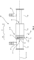
- Fig. 1 shows an exemplary embodiment of the connector tube 1 for connecting a first tube to a second tube in a schematic perspective view.
- the connector tube 1 comprises a longitudinal axis L1 and is provided with two through slits 2, 3 that completely extends through the wall 4 of the connector tube 1 in a radial direction R1 of the connector tube 1, the radial direction R1 extending perpendicular to the longitudinal axis L1.
- the through slits 2, 3 incompletely surround the longitudinal axis L1 of the connector tube 1 in the circumferential direction C1 of the connector tube 1, the circumferential direction C1 extending around the longitudinal axis L1 and for example along the outer side of the wall 4.
- the connector tube 1 may comprise more or less than the two through slits 2, 3 shown in the exemplary embodiment of Fig. 1 .
- the connector tube 1 is shown with an elastically deformable locking ring 5 for locking the first tube to the connector tube 1 in their assembled and e.g. partly telescoped state.
- the locking ring 5 is adapted to extend through the through slits 2, 3 and into a groove of the first tube in its depicted locking position P.
- the through slits 2, 3 may be arranged after each other and may be separated from each other by wall segments 6, 7 in the circumferential direction C1.
- the through slits 2, 3 may be arranged opposite to each other with respect to the longitudinal axis L1 of the connector tube1.
- the through slits 2, 3 may be formed parallel to each other.
- the lengths L of the through slits 2, 3 along the circumferential direction C1 and/or along the slits may be identical.
- the lengths L of the through slits 2, 3 and or the respective lengths of the wall segments 6, 7 may correspond to a fourth of the complete circumference of the connector tube 1.
- the locking ring 5 may comprise two latch elements 8, 9 that essentially extend perpendicular to a plane in which a main section 10 of the locking ring 5 is arranged.
- the main section 10 may extend between the two latch elements 8, 9.
- the latch elements 8, 9 may be formed by protrusions and for example by sections of the locking ring 5 that are bent out of the plane of the main section 10.
- the two latch elements 8, 9 may be formed by the free ends of the locking ring 5.
- the connector tube 1 comprises two counter latch elements 11, 12 that are arranged to form latch connections with the latch elements 8, 9 when the locking ring 5 is in its locking position P.
- the counter latch elements 11, 12 may be formed complementary to the latch elements 8, 9 and are for example provided as openings, holes or indentations in the wall 4, wherein the openings, holes or indentations open away from the longitudinal axis L1.
- the counter latch elements 11, 12 are arranged at ends 13, 14 of the through slits 2, 3, the ends 13, 14 essentially facing in the same direction.
- the connector tube 1 may comprise two holding elements 15, 16 that are adapted to form a latch connection with the latch elements 8, 9 and that are arranged to hold the locking ring 5 in its release position, in which the locking ring 5 is completely arranged outside of the groove and maybe also outside of the through slits 2, 3.
- the two holding elements 15, 16 are arranged before the counter latch elements11, 13 perpendicular to the longitudinal axis L1 of the connector tube 1.
- the holding elements 15, 16 are arranged at a distance to the ends 13, 14 of the through slits 2, 3.
- the two holding elements 15, 16 may be formed complementary to the latch elements 8, 9 and are for example provided as openings, holes or indentations in the wall 4, wherein the openings, holes or indentations open at least away from the longitudinal axis L1.
- the connector tube 1 comprises a first end 17 and a second end 18, wherein only at the first end 17, the through slits 2, 3 are formed.
- the connector tube 1 of the exemplary embodiment of Fig. 1 comprises a constant inner and/or constant outer diameter, such that the connector tube 1 can be formed easily.
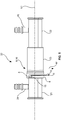
- Figs. 2 to 4 and 5 to 7 show different views and states of an exemplary embodiment of the tube assembly with another exemplary embodiment of the connector tube, wherein instead of the exemplary embodiment of the connector tube of Figs. 2 to 4 and 5 to 7 , the connector tube 1 according to the exemplary embodiment of Fig. 1 may be present.
- the connector tube 1 according to the exemplary embodiment of figure 1 may be present.
- the differences with respect to the exemplary embodiment of figure 1 are discussed in the following.
- the tube assembly 20 comprises the first tube 21 for conducting fluid, optionally a second tube 22, another embodiment of the connector tube 23 for interconnecting the first tube 21 and the second 22 in a fluid conducting manner, and the locking ring 5 that is arranged in its locking position P in Figs. 2 to 4 .
- the first tube 21 and/or the second tube 22 may comprise a branch conduit 24, 25 for connecting the tube assembly 20 to battery units of a batter pack in a fluid conducting manner.
- the branch conduits 24, 25 may extend perpendicular to a longitudinal axis A of the tube assembly 20, wherein the longitudinal axis A may coincide with the longitudinal axis L1 of the connector tube and/or each of the longitudinal axes L2, L3 of the first and second tubes 21, 22.
- the main section 10 of the locking ring 5 may face away from and an the opening of the locking ring 5 may face in the same direction as the branch conduits 24, 25.
- the holding elements 15, 16 may be arranged behind the counter latch elements 11, 12.
- Fig. 3 the tube assembly 20 is shown rotated around the longitudinal axis A, such that the branch conduits 24, 25 extend into the drawing plane and are covered by the first and second tubes 21, 22.
- the locking ring 5 in its locking position P extends through the through slits 2, 3.
- the main section 10 of the locking ring 5 may rest against the wall segment 6. Relative movements of the first tube 21 and the connector tube 23 along the longitudinal axis A are blocked by the locking ring 5.
- FIG. 4 shows a groove 26 the first tube 21 comprises along its outer circumference.
- the locking ring 5 extends not onto through the through slits 2, 3, but also into the groove 26 and forms a form fit between the first tube 21 and the connector tube 23.
- the groove 26 may extend into the wall 27 of the first tube 21.
- the connector tube 1 of the exemplary embodiment of Fig. 1 may be used.
- the groove 26 is provided between two ridges 28, 29 that are arranged on the outer side of the wall 27 and extend in a circumferential direction C2 of the first tube 21 around the longitudinal axis L2, wherein the circumferential direction C2 may correspond to the circumferential direction C1.
- a clear width between the ridges 28, 29 along the longitudinal axis A may correspond to a clear width of the through slits 2, 3 in the same direction.
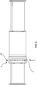
- Figs. 5 to 7 show the same embodiment as Figs. 2 to 4 in identical views, but with the locking ring 5 arranged in its release position R.
- the release position R the locking ring 5 is moved away from the locking position P perpendicular to the longitudinal axis L1 and along the radial direction R1.
- the release position R may be arranged behind the locking position P when viewed from the side of the first and/or second tubes 21, 23 from which the branch conduits 24, 25 protrude.
- the latch elements 8, 9 are latched with the holding elements 15, 16, such that the locking ring 5 is held in a captive manner and can, hence, not fall off of the connector tube 23.
- the locking ring 5 is arranged outside of the groove 26 and may at least sectionwise extend through the through slits 2, 3. Hence, relative movements between the first tube 21 and the connector tube 23 are not blocked by the locking ring 5 in its release position R.
- the main section 10 of the locking ring 5 may be arranged in a distance to the wall segment 6 in the release position R of the locking ring 5. Hence, in order to move the locking ring 5 from the release position R into its locking position P, it may suffice to press the main section 10 in particular centrally between the latch elements 8, 9 and/or between the free ends or between the latch elements 8, 9 of the locking ring 5 in the radial direction R1 towards the wall segment 6.
- the through slits 2, 3 are formed at the first end 17, and the inner diameter of a first end section 30 that includes the first end 17 and the through slits 2, 3 may be greater than the inner diameter of a middle section 31 of the connector tube 23 that neighbors the first end section 30. Hence, even if the groove 26 of the first tube 21 is formed by the ridges 28, 29, the first tube 21 with the ridges 28, 29 can still be introduced into the first end section 30.
- the first tube 26 may comprise a sealing section 33 for sealing a gap between the first tube 21 and the connection 23 and in particular its middle section 31.
- a sealing section 33 for sealing a gap between the first tube 21 and the connection 23 and in particular its middle section 31.
- at least one and maybe two sealing elements or rings can be present on the outer side of the sealing section 33 at least in the assembled state of the tube assembly 20.
- Another, second, end section 34 of the connector tube 23, that is arranged opposite to the first end section 30 may comprise an inner diameter that corresponds to the inner diameter of the middle section 31.
- the second tube 22 may comprise a sealing section 35 for sealing a gap between the first tube 22 and the connector tube 23 and in particular its second end section 34.
- at least one and maybe two sealing elements or rings can be present on the outer side of the sealing section 35 at least in the assembled state of the tube assembly 20.
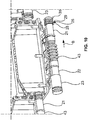
- Figs. 8 to 10 show an exemplary embodiment of a battery pack with the tube assembly of the exemplary embodiments shown in Figs 2 to 7 in schematic perspective views.
- Fig. 8 shows an overview of the battery pack and
- Figs. 9 and 10 show enlarged details of the battery pack.
- the connector tube 23 instead of the connector tube 23, the connector tube 1 may be used.
- the battery pack 40 comprises a plurality of battery units 41, which each comprises a plurality of battery modules and which are arranged one after the other along a longitudinal direction B of the battery pack 40. Furthermore, the battery pack 40 comprises a fluid distribution system 42 comprising the tube assembly20.
- the connector tube 23 may at least partly be arranged between adjacent battery modules 41 along the longitudinal axis A.
- the longitudinal axis of the fluid distribution system 42 may correspond to the longitudinal axis A, which is, however, not shown in Figs. 8 to 10 , for the sake of simplicity.
- the connector tube 23 can succeed the first tube 21
- the second tube 22 can succeed the connector tube 23 and a bellow 43 or gaiter can succeed the second tube 22.
- a bellow 43 or gaiter can succeed the second tube 22.
- the bellow 43 or gaiter may be arranged between gaps 44 between adjacent battery modules 41.
- All connector tubes 23 of the tube assembly 20 may be oriented in the same direction, such that for example the first ends 17 face against the longitudinal direction B.
Landscapes
- Engineering & Computer Science (AREA)
- Chemical & Material Sciences (AREA)
- Chemical Kinetics & Catalysis (AREA)
- Electrochemistry (AREA)
- General Chemical & Material Sciences (AREA)
- Manufacturing & Machinery (AREA)
- Mechanical Engineering (AREA)
- General Engineering & Computer Science (AREA)
- Transportation (AREA)
- Sustainable Energy (AREA)
- Life Sciences & Earth Sciences (AREA)
- Sustainable Development (AREA)
- Power Engineering (AREA)
- Combustion & Propulsion (AREA)
- Battery Mounting, Suspending (AREA)
- Quick-Acting Or Multi-Walled Pipe Joints (AREA)
Priority Applications (7)
| Application Number | Priority Date | Filing Date | Title |
|---|---|---|---|
| EP18154418.0A EP3522291B1 (de) | 2018-01-31 | 2018-01-31 | Rohranordnung für ein flüssigkeitsverteilungssystem eines batteriepacks eines fahrzeugs und batteriepack für ein fahrzeug |
| HUE18154418A HUE057462T2 (hu) | 2018-01-31 | 2018-01-31 | Csõ összeállítás egy jármû akkumulátor csomagjának folyadék elosztó rendszeréhez, és akkumulátor csomag egy jármûhöz |
| PL18154418T PL3522291T3 (pl) | 2018-01-31 | 2018-01-31 | Zespół rurkowy do systemu dystrybucji płynu z pakietu akumulatorowego pojazdu i pakiet akumulatorowy do pojazdu |
| KR1020190010368A KR102671852B1 (ko) | 2018-01-31 | 2019-01-28 | 차량 전지 팩의 유체 분배 시스템용 튜브 조립체 및 차량용 전지 팩 |
| CN201980010932.5A CN111699337B (zh) | 2018-01-31 | 2019-01-29 | 用于车辆电池包的流体分配系统的管组件和用于车辆的电池包 |
| US16/954,802 US20210098841A1 (en) | 2018-01-31 | 2019-01-29 | Tube assembly for a fluid distribution system of a battery pack of a vehicle and battery pack for a vehicle |
| PCT/KR2019/001193 WO2019151741A1 (ko) | 2018-01-31 | 2019-01-29 | 차량 전지 팩의 유체 분배 시스템용 튜브 조립체 및 차량용 전지 팩 |
Applications Claiming Priority (1)
| Application Number | Priority Date | Filing Date | Title |
|---|---|---|---|
| EP18154418.0A EP3522291B1 (de) | 2018-01-31 | 2018-01-31 | Rohranordnung für ein flüssigkeitsverteilungssystem eines batteriepacks eines fahrzeugs und batteriepack für ein fahrzeug |
Publications (2)
| Publication Number | Publication Date |
|---|---|
| EP3522291A1 true EP3522291A1 (de) | 2019-08-07 |
| EP3522291B1 EP3522291B1 (de) | 2021-09-29 |
Family
ID=61132156
Family Applications (1)
| Application Number | Title | Priority Date | Filing Date |
|---|---|---|---|
| EP18154418.0A Active EP3522291B1 (de) | 2018-01-31 | 2018-01-31 | Rohranordnung für ein flüssigkeitsverteilungssystem eines batteriepacks eines fahrzeugs und batteriepack für ein fahrzeug |
Country Status (4)
| Country | Link |
|---|---|
| US (1) | US20210098841A1 (de) |
| EP (1) | EP3522291B1 (de) |
| HU (1) | HUE057462T2 (de) |
| PL (1) | PL3522291T3 (de) |
Cited By (5)
| Publication number | Priority date | Publication date | Assignee | Title |
|---|---|---|---|---|
| CN110726023A (zh) * | 2019-09-30 | 2020-01-24 | 廊坊舒畅汽车零部件有限公司 | 接头组件及充电套件 |
| CN114079097A (zh) * | 2020-08-20 | 2022-02-22 | 保时捷股份公司 | 高压电池、制造高压电池的方法及具有其的机动车辆 |
| US20220243849A1 (en) * | 2021-01-29 | 2022-08-04 | Hutchinson Fluid Management Systems, Inc. | High tolerance quick connect coupling |
| US11721856B2 (en) | 2018-10-12 | 2023-08-08 | Samsung Sdi Co., Ltd. | Battery pack for a vehicle |
| EP4145595A4 (de) * | 2020-12-07 | 2023-12-06 | LG Energy Solution, Ltd. | Batteriepack und fahrzeug mit batteriepack |
Citations (8)
| Publication number | Priority date | Publication date | Assignee | Title |
|---|---|---|---|---|
| FR2280852A1 (fr) * | 1974-08-01 | 1976-02-27 | Lechler Apparatebau Kg | Dispositif de fixation d'une buse sur un tuyau d'une conduite d'eau, notamment |
| DE19951429A1 (de) * | 1999-10-26 | 2001-05-03 | Behr Gmbh & Co | Rohranschluß für einen Ölkühler |
| EP2017520A2 (de) * | 2007-07-19 | 2009-01-21 | Gustav Wahler GmbH u. Co.KG | Befestigungsvorrichtung |
| US20110303593A1 (en) * | 2010-06-14 | 2011-12-15 | Agilent Technologies, Inc. | Fitting Element with Grip Force Distributor |
| WO2012117697A1 (ja) * | 2011-02-28 | 2012-09-07 | 株式会社ニフコ | 管構造体及びこれを用いたバッテリ温調システム |
| EP2610947A2 (de) * | 2010-08-23 | 2013-07-03 | LG Chem, Ltd. | Batteriesystem mit einem verteilerelement und einem verbindungsstück sowie verteileranordnung |
| EP3121501A1 (de) * | 2015-07-22 | 2017-01-25 | Dr. Ing. h.c. F. Porsche AG | Fahrzeugkomponente und kraftfahrzeug |
| EP3179148A1 (de) * | 2014-08-07 | 2017-06-14 | Nifco Inc. | Verriegelungsmechanismus für einen rohrförmigen körper |
Family Cites Families (6)
| Publication number | Priority date | Publication date | Assignee | Title |
|---|---|---|---|---|
| US5683117A (en) * | 1995-12-14 | 1997-11-04 | Flex Technologies, Inc. | Retainer clip for a connector |
| US6302451B1 (en) * | 2000-03-15 | 2001-10-16 | Dana Corporation | Quick-connect hose end couplings |
| JP4252785B2 (ja) * | 2002-10-01 | 2009-04-08 | 株式会社パイオラックス | 配管用コネクタ及びその製造方法 |
| DE202009000328U1 (de) * | 2009-01-08 | 2009-03-19 | Norma Germany Gmbh | Kupplungseinrichtung |
| US9188267B2 (en) * | 2010-05-04 | 2015-11-17 | Norma U.S. Holding Llc | Connector assembly with retainer for joining fluid conduits |
| EP3364090B1 (de) * | 2017-12-11 | 2020-02-19 | TI Automotive (Fuldabrück) GmbH | Verbinder zum verbinden zweier fluidführender elemente |
-
2018
- 2018-01-31 HU HUE18154418A patent/HUE057462T2/hu unknown
- 2018-01-31 PL PL18154418T patent/PL3522291T3/pl unknown
- 2018-01-31 EP EP18154418.0A patent/EP3522291B1/de active Active
-
2019
- 2019-01-29 US US16/954,802 patent/US20210098841A1/en not_active Abandoned
Patent Citations (8)
| Publication number | Priority date | Publication date | Assignee | Title |
|---|---|---|---|---|
| FR2280852A1 (fr) * | 1974-08-01 | 1976-02-27 | Lechler Apparatebau Kg | Dispositif de fixation d'une buse sur un tuyau d'une conduite d'eau, notamment |
| DE19951429A1 (de) * | 1999-10-26 | 2001-05-03 | Behr Gmbh & Co | Rohranschluß für einen Ölkühler |
| EP2017520A2 (de) * | 2007-07-19 | 2009-01-21 | Gustav Wahler GmbH u. Co.KG | Befestigungsvorrichtung |
| US20110303593A1 (en) * | 2010-06-14 | 2011-12-15 | Agilent Technologies, Inc. | Fitting Element with Grip Force Distributor |
| EP2610947A2 (de) * | 2010-08-23 | 2013-07-03 | LG Chem, Ltd. | Batteriesystem mit einem verteilerelement und einem verbindungsstück sowie verteileranordnung |
| WO2012117697A1 (ja) * | 2011-02-28 | 2012-09-07 | 株式会社ニフコ | 管構造体及びこれを用いたバッテリ温調システム |
| EP3179148A1 (de) * | 2014-08-07 | 2017-06-14 | Nifco Inc. | Verriegelungsmechanismus für einen rohrförmigen körper |
| EP3121501A1 (de) * | 2015-07-22 | 2017-01-25 | Dr. Ing. h.c. F. Porsche AG | Fahrzeugkomponente und kraftfahrzeug |
Cited By (6)
| Publication number | Priority date | Publication date | Assignee | Title |
|---|---|---|---|---|
| US11721856B2 (en) | 2018-10-12 | 2023-08-08 | Samsung Sdi Co., Ltd. | Battery pack for a vehicle |
| CN110726023A (zh) * | 2019-09-30 | 2020-01-24 | 廊坊舒畅汽车零部件有限公司 | 接头组件及充电套件 |
| CN110726023B (zh) * | 2019-09-30 | 2021-07-20 | 廊坊舒畅汽车零部件有限公司 | 接头组件及充电套件 |
| CN114079097A (zh) * | 2020-08-20 | 2022-02-22 | 保时捷股份公司 | 高压电池、制造高压电池的方法及具有其的机动车辆 |
| EP4145595A4 (de) * | 2020-12-07 | 2023-12-06 | LG Energy Solution, Ltd. | Batteriepack und fahrzeug mit batteriepack |
| US20220243849A1 (en) * | 2021-01-29 | 2022-08-04 | Hutchinson Fluid Management Systems, Inc. | High tolerance quick connect coupling |
Also Published As
| Publication number | Publication date |
|---|---|
| HUE057462T2 (hu) | 2022-05-28 |
| KR20190093140A (ko) | 2019-08-08 |
| US20210098841A1 (en) | 2021-04-01 |
| EP3522291B1 (de) | 2021-09-29 |
| PL3522291T3 (pl) | 2022-01-31 |
Similar Documents
| Publication | Publication Date | Title |
|---|---|---|
| EP3522291B1 (de) | Rohranordnung für ein flüssigkeitsverteilungssystem eines batteriepacks eines fahrzeugs und batteriepack für ein fahrzeug | |
| CN106935927B (zh) | 电池模块和包括其的车辆 | |
| US20100092849A1 (en) | Battery module | |
| EP1958276B1 (de) | Zusammenbaubares abstandsglied zur herstellung eines batteriemoduls | |
| US8852782B2 (en) | Battery pack having novel structure | |
| EP3800694B1 (de) | Batteriezellenanordnung, batteriemodul mit derselben batteriezellenanordnung, batteriepack mit dem gleichen batteriemodul und automobil mit dem gleichen batteriepack | |
| KR102421779B1 (ko) | 전지 시스템 | |
| US11721856B2 (en) | Battery pack for a vehicle | |
| CN108376755B (zh) | 用于电动车辆的电池 | |
| US20090011326A1 (en) | Battery system | |
| CN111699337B (zh) | 用于车辆电池包的流体分配系统的管组件和用于车辆的电池包 | |
| KR20170078015A (ko) | 배터리 팩 | |
| EP3772122B1 (de) | Batteriemodul mit einer multifunktionalen endplatte | |
| KR102671852B1 (ko) | 차량 전지 팩의 유체 분배 시스템용 튜브 조립체 및 차량용 전지 팩 | |
| US11476521B2 (en) | Fluid connector for a battery pack of a vehicle, and battery pack for a vehicle including the same | |
| EP3637536B1 (de) | Kupplungselement für ein batteriepaket eines fahrzeugs | |
| EP3890054B1 (de) | Batteriesystem und fahrzeug mit mindestens einem batteriesystem | |
| CN113471641B (zh) | 电池系统和包括至少一个电池系统的车辆 | |
| EP4170790A1 (de) | Batteriesystem mit zylindrischen zellen und temperatursensor und verfahren zur installation davon | |
| US20230130350A1 (en) | Battery system comprising cylindrical cells and a temperature sensor and method of installing the same | |
| EP4047730B1 (de) | Batteriesystem und fahrzeug mit dem batteriesystem | |
| US20230122982A1 (en) | Battery module, a battery pack, an electric vehicle, a bmm carrier, a bmm arrangement and a method for assembling a battery module |
Legal Events
| Date | Code | Title | Description |
|---|---|---|---|
| PUAI | Public reference made under article 153(3) epc to a published international application that has entered the european phase |
Free format text: ORIGINAL CODE: 0009012 |
|
| STAA | Information on the status of an ep patent application or granted ep patent |
Free format text: STATUS: REQUEST FOR EXAMINATION WAS MADE |
|
| 17P | Request for examination filed |
Effective date: 20181217 |
|
| AK | Designated contracting states |
Kind code of ref document: A1 Designated state(s): AL AT BE BG CH CY CZ DE DK EE ES FI FR GB GR HR HU IE IS IT LI LT LU LV MC MK MT NL NO PL PT RO RS SE SI SK SM TR |
|
| AX | Request for extension of the european patent |
Extension state: BA ME |
|
| STAA | Information on the status of an ep patent application or granted ep patent |
Free format text: STATUS: EXAMINATION IS IN PROGRESS |
|
| STAA | Information on the status of an ep patent application or granted ep patent |
Free format text: STATUS: EXAMINATION IS IN PROGRESS |
|
| 17Q | First examination report despatched |
Effective date: 20201026 |
|
| GRAP | Despatch of communication of intention to grant a patent |
Free format text: ORIGINAL CODE: EPIDOSNIGR1 |
|
| STAA | Information on the status of an ep patent application or granted ep patent |
Free format text: STATUS: GRANT OF PATENT IS INTENDED |
|
| RIC1 | Information provided on ipc code assigned before grant |
Ipc: F16L 37/14 20060101ALI20210602BHEP Ipc: H01M 50/20 20210101ALI20210602BHEP Ipc: F16L 37/088 20060101ALI20210602BHEP Ipc: H01M 10/625 20140101ALI20210602BHEP Ipc: H01M 10/613 20140101ALI20210602BHEP Ipc: H01M 10/6567 20140101AFI20210602BHEP |
|
| INTG | Intention to grant announced |
Effective date: 20210702 |
|
| GRAS | Grant fee paid |
Free format text: ORIGINAL CODE: EPIDOSNIGR3 |
|
| GRAA | (expected) grant |
Free format text: ORIGINAL CODE: 0009210 |
|
| STAA | Information on the status of an ep patent application or granted ep patent |
Free format text: STATUS: THE PATENT HAS BEEN GRANTED |
|
| AK | Designated contracting states |
Kind code of ref document: B1 Designated state(s): AL AT BE BG CH CY CZ DE DK EE ES FI FR GB GR HR HU IE IS IT LI LT LU LV MC MK MT NL NO PL PT RO RS SE SI SK SM TR |
|
| REG | Reference to a national code |
Ref country code: GB Ref legal event code: FG4D |
|
| REG | Reference to a national code |
Ref country code: CH Ref legal event code: EP Ref country code: AT Ref legal event code: REF Ref document number: 1434994 Country of ref document: AT Kind code of ref document: T Effective date: 20211015 |
|
| REG | Reference to a national code |
Ref country code: DE Ref legal event code: R096 Ref document number: 602018024118 Country of ref document: DE |
|
| REG | Reference to a national code |
Ref country code: IE Ref legal event code: FG4D |
|
| REG | Reference to a national code |
Ref country code: LT Ref legal event code: MG9D |
|
| PG25 | Lapsed in a contracting state [announced via postgrant information from national office to epo] |
Ref country code: SE Free format text: LAPSE BECAUSE OF FAILURE TO SUBMIT A TRANSLATION OF THE DESCRIPTION OR TO PAY THE FEE WITHIN THE PRESCRIBED TIME-LIMIT Effective date: 20210929 Ref country code: RS Free format text: LAPSE BECAUSE OF FAILURE TO SUBMIT A TRANSLATION OF THE DESCRIPTION OR TO PAY THE FEE WITHIN THE PRESCRIBED TIME-LIMIT Effective date: 20210929 Ref country code: FI Free format text: LAPSE BECAUSE OF FAILURE TO SUBMIT A TRANSLATION OF THE DESCRIPTION OR TO PAY THE FEE WITHIN THE PRESCRIBED TIME-LIMIT Effective date: 20210929 Ref country code: HR Free format text: LAPSE BECAUSE OF FAILURE TO SUBMIT A TRANSLATION OF THE DESCRIPTION OR TO PAY THE FEE WITHIN THE PRESCRIBED TIME-LIMIT Effective date: 20210929 Ref country code: NO Free format text: LAPSE BECAUSE OF FAILURE TO SUBMIT A TRANSLATION OF THE DESCRIPTION OR TO PAY THE FEE WITHIN THE PRESCRIBED TIME-LIMIT Effective date: 20211229 Ref country code: BG Free format text: LAPSE BECAUSE OF FAILURE TO SUBMIT A TRANSLATION OF THE DESCRIPTION OR TO PAY THE FEE WITHIN THE PRESCRIBED TIME-LIMIT Effective date: 20211229 Ref country code: LT Free format text: LAPSE BECAUSE OF FAILURE TO SUBMIT A TRANSLATION OF THE DESCRIPTION OR TO PAY THE FEE WITHIN THE PRESCRIBED TIME-LIMIT Effective date: 20210929 |
|
| REG | Reference to a national code |
Ref country code: NL Ref legal event code: MP Effective date: 20210929 |
|
| PG25 | Lapsed in a contracting state [announced via postgrant information from national office to epo] |
Ref country code: LV Free format text: LAPSE BECAUSE OF FAILURE TO SUBMIT A TRANSLATION OF THE DESCRIPTION OR TO PAY THE FEE WITHIN THE PRESCRIBED TIME-LIMIT Effective date: 20210929 Ref country code: GR Free format text: LAPSE BECAUSE OF FAILURE TO SUBMIT A TRANSLATION OF THE DESCRIPTION OR TO PAY THE FEE WITHIN THE PRESCRIBED TIME-LIMIT Effective date: 20211230 |
|
| REG | Reference to a national code |
Ref country code: HU Ref legal event code: AG4A Ref document number: E057462 Country of ref document: HU |
|
| PG25 | Lapsed in a contracting state [announced via postgrant information from national office to epo] |
Ref country code: IS Free format text: LAPSE BECAUSE OF FAILURE TO SUBMIT A TRANSLATION OF THE DESCRIPTION OR TO PAY THE FEE WITHIN THE PRESCRIBED TIME-LIMIT Effective date: 20220129 Ref country code: SK Free format text: LAPSE BECAUSE OF FAILURE TO SUBMIT A TRANSLATION OF THE DESCRIPTION OR TO PAY THE FEE WITHIN THE PRESCRIBED TIME-LIMIT Effective date: 20210929 Ref country code: RO Free format text: LAPSE BECAUSE OF FAILURE TO SUBMIT A TRANSLATION OF THE DESCRIPTION OR TO PAY THE FEE WITHIN THE PRESCRIBED TIME-LIMIT Effective date: 20210929 Ref country code: PT Free format text: LAPSE BECAUSE OF FAILURE TO SUBMIT A TRANSLATION OF THE DESCRIPTION OR TO PAY THE FEE WITHIN THE PRESCRIBED TIME-LIMIT Effective date: 20220131 Ref country code: NL Free format text: LAPSE BECAUSE OF FAILURE TO SUBMIT A TRANSLATION OF THE DESCRIPTION OR TO PAY THE FEE WITHIN THE PRESCRIBED TIME-LIMIT Effective date: 20210929 Ref country code: ES Free format text: LAPSE BECAUSE OF FAILURE TO SUBMIT A TRANSLATION OF THE DESCRIPTION OR TO PAY THE FEE WITHIN THE PRESCRIBED TIME-LIMIT Effective date: 20210929 Ref country code: EE Free format text: LAPSE BECAUSE OF FAILURE TO SUBMIT A TRANSLATION OF THE DESCRIPTION OR TO PAY THE FEE WITHIN THE PRESCRIBED TIME-LIMIT Effective date: 20210929 Ref country code: CZ Free format text: LAPSE BECAUSE OF FAILURE TO SUBMIT A TRANSLATION OF THE DESCRIPTION OR TO PAY THE FEE WITHIN THE PRESCRIBED TIME-LIMIT Effective date: 20210929 Ref country code: AL Free format text: LAPSE BECAUSE OF FAILURE TO SUBMIT A TRANSLATION OF THE DESCRIPTION OR TO PAY THE FEE WITHIN THE PRESCRIBED TIME-LIMIT Effective date: 20210929 |
|
| REG | Reference to a national code |
Ref country code: DE Ref legal event code: R097 Ref document number: 602018024118 Country of ref document: DE |
|
| PG25 | Lapsed in a contracting state [announced via postgrant information from national office to epo] |
Ref country code: DK Free format text: LAPSE BECAUSE OF FAILURE TO SUBMIT A TRANSLATION OF THE DESCRIPTION OR TO PAY THE FEE WITHIN THE PRESCRIBED TIME-LIMIT Effective date: 20210929 |
|
| PLBE | No opposition filed within time limit |
Free format text: ORIGINAL CODE: 0009261 |
|
| STAA | Information on the status of an ep patent application or granted ep patent |
Free format text: STATUS: NO OPPOSITION FILED WITHIN TIME LIMIT |
|
| PG25 | Lapsed in a contracting state [announced via postgrant information from national office to epo] |
Ref country code: MC Free format text: LAPSE BECAUSE OF FAILURE TO SUBMIT A TRANSLATION OF THE DESCRIPTION OR TO PAY THE FEE WITHIN THE PRESCRIBED TIME-LIMIT Effective date: 20210929 |
|
| REG | Reference to a national code |
Ref country code: CH Ref legal event code: PL |
|
| 26N | No opposition filed |
Effective date: 20220630 |
|
| REG | Reference to a national code |
Ref country code: BE Ref legal event code: MM Effective date: 20220131 |
|
| PG25 | Lapsed in a contracting state [announced via postgrant information from national office to epo] |
Ref country code: LU Free format text: LAPSE BECAUSE OF NON-PAYMENT OF DUE FEES Effective date: 20220131 |
|
| PG25 | Lapsed in a contracting state [announced via postgrant information from national office to epo] |
Ref country code: SI Free format text: LAPSE BECAUSE OF FAILURE TO SUBMIT A TRANSLATION OF THE DESCRIPTION OR TO PAY THE FEE WITHIN THE PRESCRIBED TIME-LIMIT Effective date: 20210929 Ref country code: BE Free format text: LAPSE BECAUSE OF NON-PAYMENT OF DUE FEES Effective date: 20220131 |
|
| PG25 | Lapsed in a contracting state [announced via postgrant information from national office to epo] |
Ref country code: LI Free format text: LAPSE BECAUSE OF NON-PAYMENT OF DUE FEES Effective date: 20220131 Ref country code: CH Free format text: LAPSE BECAUSE OF NON-PAYMENT OF DUE FEES Effective date: 20220131 |
|
| PG25 | Lapsed in a contracting state [announced via postgrant information from national office to epo] |
Ref country code: IT Free format text: LAPSE BECAUSE OF FAILURE TO SUBMIT A TRANSLATION OF THE DESCRIPTION OR TO PAY THE FEE WITHIN THE PRESCRIBED TIME-LIMIT Effective date: 20210929 Ref country code: IE Free format text: LAPSE BECAUSE OF NON-PAYMENT OF DUE FEES Effective date: 20220131 |
|
| PGFP | Annual fee paid to national office [announced via postgrant information from national office to epo] |
Ref country code: PL Payment date: 20230112 Year of fee payment: 6 |
|
| P01 | Opt-out of the competence of the unified patent court (upc) registered |
Effective date: 20230528 |
|
| PGFP | Annual fee paid to national office [announced via postgrant information from national office to epo] |
Ref country code: GB Payment date: 20231221 Year of fee payment: 7 |
|
| PGFP | Annual fee paid to national office [announced via postgrant information from national office to epo] |
Ref country code: FR Payment date: 20231222 Year of fee payment: 7 |
|
| REG | Reference to a national code |
Ref country code: AT Ref legal event code: UEP Ref document number: 1434994 Country of ref document: AT Kind code of ref document: T Effective date: 20210929 |
|
| PGFP | Annual fee paid to national office [announced via postgrant information from national office to epo] |
Ref country code: AT Payment date: 20231227 Year of fee payment: 7 |
|
| PG25 | Lapsed in a contracting state [announced via postgrant information from national office to epo] |
Ref country code: SM Free format text: LAPSE BECAUSE OF FAILURE TO SUBMIT A TRANSLATION OF THE DESCRIPTION OR TO PAY THE FEE WITHIN THE PRESCRIBED TIME-LIMIT Effective date: 20210929 Ref country code: MK Free format text: LAPSE BECAUSE OF FAILURE TO SUBMIT A TRANSLATION OF THE DESCRIPTION OR TO PAY THE FEE WITHIN THE PRESCRIBED TIME-LIMIT Effective date: 20210929 Ref country code: CY Free format text: LAPSE BECAUSE OF FAILURE TO SUBMIT A TRANSLATION OF THE DESCRIPTION OR TO PAY THE FEE WITHIN THE PRESCRIBED TIME-LIMIT Effective date: 20210929 |
|
| PGFP | Annual fee paid to national office [announced via postgrant information from national office to epo] |
Ref country code: HU Payment date: 20240111 Year of fee payment: 7 Ref country code: DE Payment date: 20231228 Year of fee payment: 7 |