EP3522250B1 - Kappenanordnung und leistungsbatterie - Google Patents
Kappenanordnung und leistungsbatterie Download PDFInfo
- Publication number
- EP3522250B1 EP3522250B1 EP18165104.3A EP18165104A EP3522250B1 EP 3522250 B1 EP3522250 B1 EP 3522250B1 EP 18165104 A EP18165104 A EP 18165104A EP 3522250 B1 EP3522250 B1 EP 3522250B1
- Authority
- EP
- European Patent Office
- Prior art keywords
- liquid injection
- injection hole
- cap
- plate
- cap plate
- Prior art date
- Legal status (The legal status is an assumption and is not a legal conclusion. Google has not performed a legal analysis and makes no representation as to the accuracy of the status listed.)
- Active
Links
Images


Classifications
-
- H—ELECTRICITY
- H01—ELECTRIC ELEMENTS
- H01M—PROCESSES OR MEANS, e.g. BATTERIES, FOR THE DIRECT CONVERSION OF CHEMICAL ENERGY INTO ELECTRICAL ENERGY
- H01M10/00—Secondary cells; Manufacture thereof
- H01M10/04—Construction or manufacture in general
- H01M10/0431—Cells with wound or folded electrodes
-
- H—ELECTRICITY
- H01—ELECTRIC ELEMENTS
- H01M—PROCESSES OR MEANS, e.g. BATTERIES, FOR THE DIRECT CONVERSION OF CHEMICAL ENERGY INTO ELECTRICAL ENERGY
- H01M50/00—Constructional details or processes of manufacture of the non-active parts of electrochemical cells other than fuel cells, e.g. hybrid cells
- H01M50/10—Primary casings; Jackets or wrappings
- H01M50/147—Lids or covers
- H01M50/148—Lids or covers characterised by their shape
- H01M50/15—Lids or covers characterised by their shape for prismatic or rectangular cells
-
- H—ELECTRICITY
- H01—ELECTRIC ELEMENTS
- H01M—PROCESSES OR MEANS, e.g. BATTERIES, FOR THE DIRECT CONVERSION OF CHEMICAL ENERGY INTO ELECTRICAL ENERGY
- H01M50/00—Constructional details or processes of manufacture of the non-active parts of electrochemical cells other than fuel cells, e.g. hybrid cells
- H01M50/10—Primary casings; Jackets or wrappings
- H01M50/147—Lids or covers
- H01M50/148—Lids or covers characterised by their shape
- H01M50/154—Lid or cover comprising an axial bore for receiving a central current collector
-
- H—ELECTRICITY
- H01—ELECTRIC ELEMENTS
- H01M—PROCESSES OR MEANS, e.g. BATTERIES, FOR THE DIRECT CONVERSION OF CHEMICAL ENERGY INTO ELECTRICAL ENERGY
- H01M50/00—Constructional details or processes of manufacture of the non-active parts of electrochemical cells other than fuel cells, e.g. hybrid cells
- H01M50/30—Arrangements for facilitating escape of gases
-
- H—ELECTRICITY
- H01—ELECTRIC ELEMENTS
- H01M—PROCESSES OR MEANS, e.g. BATTERIES, FOR THE DIRECT CONVERSION OF CHEMICAL ENERGY INTO ELECTRICAL ENERGY
- H01M50/00—Constructional details or processes of manufacture of the non-active parts of electrochemical cells other than fuel cells, e.g. hybrid cells
- H01M50/60—Arrangements or processes for filling or topping-up with liquids; Arrangements or processes for draining liquids from casings
- H01M50/609—Arrangements or processes for filling with liquid, e.g. electrolytes
- H01M50/627—Filling ports
- H01M50/636—Closing or sealing filling ports, e.g. using lids
-
- H—ELECTRICITY
- H01—ELECTRIC ELEMENTS
- H01M—PROCESSES OR MEANS, e.g. BATTERIES, FOR THE DIRECT CONVERSION OF CHEMICAL ENERGY INTO ELECTRICAL ENERGY
- H01M50/00—Constructional details or processes of manufacture of the non-active parts of electrochemical cells other than fuel cells, e.g. hybrid cells
- H01M50/60—Arrangements or processes for filling or topping-up with liquids; Arrangements or processes for draining liquids from casings
- H01M50/609—Arrangements or processes for filling with liquid, e.g. electrolytes
- H01M50/627—Filling ports
- H01M50/636—Closing or sealing filling ports, e.g. using lids
- H01M50/645—Plugs
- H01M50/655—Plugs specially adapted for venting
-
- Y—GENERAL TAGGING OF NEW TECHNOLOGICAL DEVELOPMENTS; GENERAL TAGGING OF CROSS-SECTIONAL TECHNOLOGIES SPANNING OVER SEVERAL SECTIONS OF THE IPC; TECHNICAL SUBJECTS COVERED BY FORMER USPC CROSS-REFERENCE ART COLLECTIONS [XRACs] AND DIGESTS
- Y02—TECHNOLOGIES OR APPLICATIONS FOR MITIGATION OR ADAPTATION AGAINST CLIMATE CHANGE
- Y02E—REDUCTION OF GREENHOUSE GAS [GHG] EMISSIONS, RELATED TO ENERGY GENERATION, TRANSMISSION OR DISTRIBUTION
- Y02E60/00—Enabling technologies; Technologies with a potential or indirect contribution to GHG emissions mitigation
- Y02E60/10—Energy storage using batteries
-
- Y—GENERAL TAGGING OF NEW TECHNOLOGICAL DEVELOPMENTS; GENERAL TAGGING OF CROSS-SECTIONAL TECHNOLOGIES SPANNING OVER SEVERAL SECTIONS OF THE IPC; TECHNICAL SUBJECTS COVERED BY FORMER USPC CROSS-REFERENCE ART COLLECTIONS [XRACs] AND DIGESTS
- Y02—TECHNOLOGIES OR APPLICATIONS FOR MITIGATION OR ADAPTATION AGAINST CLIMATE CHANGE
- Y02P—CLIMATE CHANGE MITIGATION TECHNOLOGIES IN THE PRODUCTION OR PROCESSING OF GOODS
- Y02P70/00—Climate change mitigation technologies in the production process for final industrial or consumer products
- Y02P70/50—Manufacturing or production processes characterised by the final manufactured product
Definitions
- the present disclosure relates to the technical field of power battery, particularly to a cap assembly and a power battery.
- a secondary battery generally includes an electrode assembly, a case, and a cap assembly.
- the electrode assembly is formed by a positive electrode sheet, a negative electrode sheet, and a separating membrane disposed between the positive electrode sheet and the negative electrode sheet that are wound around a winding axis.
- the electrode assembly is received in the case, and the cap assembly is assembled with the case and disposed in correspondence to an end portion of the electrode assembly along the winding axis.
- the cap assembly includes a cap plate and an electrode terminal disposed on the cap sheet, wherein an electrode tab of the electrode assembly is electrically connected with the electrode terminal of the cap assembly.
- the cap plate is provided with a liquid injection hole communicating with a sealed space.
- the present disclosure provides a cap assembly and a power battery.
- the flow direction of the electrolyte can be changed and the impact force on the end of the electrode assembly can be reduced during liquid injection.
- the present disclosure provides a cap assembly for a power battery in accordance with claim 1.
- the cap plate comprises a boss provided on the bottom surface, disposed in correspondence to the first end, and adapted to press against an electrode assembly of the power battery, wherein the blocking member is connected to the boss and has a bottom face flush with that of the boss.
- a ratio of a surface area of the vent plate located inside the annular seam to a cross-sectional area of the liquid injection hole is of 1.5 to 10.
- the top surface of the cap plate is provided with a recess depressed toward the bottom surface, wherein the liquid injection hole communicates with the recess and the vent plate is accommodated in the recess.
- the cap assembly of the embodiment of the present disclosure includes a cap plate which has a liquid injection hole and a blocking member which is disposed on the cap plate and used for covering the liquid injection hole.
- the electrolyte injected from the liquid injection hole can be blocked by the blocking member during electrolyte injection operation of the power battery, resulting in that the flow direction of the electrolyte changes and the electrolyte no longer continues to flow along the axis of the liquid injection hole.
- the flow rate of the electrolyte can be reduced by the blocking member, so that the impact force exerted by the electrolyte on the end portion of the electrode assembly included in the power battery can be reduced compared to the case that the electrolyte discharges directly from the liquid injection hole, and the probability of the displacement of the separating membrane included in the electrode assembly caused by a large impact force can be reduced, thereby improving the safety performance of the power battery.
- the invention also extends to a power battery as defined in claim 5.
- the term of “multiple” means two or more unless otherwise specified; the terms of “upper”, “lower”, “left”, “right”, “inner”, “outer” and the like are merely used for conveniently and simply describing the present disclosure, rather than indicating or implying that the referred device or element must have a particular orientation, or be constructed and operated in a particular orientation, and thus cannot be understood as a limitation to the present disclosure.
- the terms of “first”, “second” and the like are only used for descriptive purposes and are not to be construed as indicating or implying relative importance.
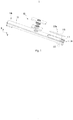
- Fig. 1 schematically shows an exploded structure of a cap assembly according to an embodiment of the present disclosure.
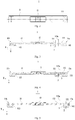
- Fig. 2 schematically shows a structure of a cap assembly according to an embodiment of the present disclosure in a top view.
- Fig. 3 schematically shows a structure of a cap assembly according to an embodiment of the present disclosure in a sectional view.
- Fig. 4 schematically shows a structure of a cap assembly according to another embodiment of the present disclosure in a sectional view.
- Fig. 5 schematically shows a structure of a cap assembly according to another embodiment of the present disclosure in a sectional view.
- FIG. 1 schematically shows an exploded structure of a cap assembly according to an embodiment of the present disclosure.
- Fig. 2 schematically shows a structure of a cap assembly according to an embodiment of the present disclosure in a top view.
- Fig. 3 schematically shows a structure of a cap assembly according to an embodiment of the present disclosure in a sectional view.
- Fig. 4 schematically shows a structure of
- FIG. 6 schematically shows an exploded structure of a power battery according to an embodiment of the present disclosure.
- Fig. 7 schematic shows a structure of a power battery according to an embodiment of the present disclosure in a sectional view.
- Fig. 8 schematically a structure of a power battery according to another embodiment of the present disclosure in a sectional view.
- the cap assembly 1 can be applied to a power battery.
- the power battery of the present disclosure includes a case 4, an electrode assembly 5, and the cap assembly 1.
- the electrode assembly of the present disclosure is formed by a positive electrode sheet, a negative electrode sheet, and a separating membrane disposed between the positive electrode sheet and the negative electrode sheet, that are wound around a winding axis.
- the electrode assembly 5 has two end portions opposed to each other along the winding axis.
- the positive electrode sheet, the negative electrode sheet, and the separating membrane provided between the positive electrode sheet and the negative electrode sheet are wound, forming a spiral coil as seen from at each end portion.
- the electrode assembly 5 is disposed in the case 4, and the cap assembly 1 is disposed in correspondence to the end portion of the electrode assembly 5.
- the cap assembly 1 in the present disclosure includes a cap plate 11, an electrode terminal 12 disposed on the cap plate 11, and a blocking member 2 disposed on the cap plate 11.
- the cap plate 11 of the present disclosure has a predetermined length, width and thickness. Referring to an orientation of the cap assembly 1 as shown in Fig. 1 , a thickness direction of the cap plate 11 is consistent with a thickness direction X, a length direction of the cap plate 11 is consistent with a length direction Y, and a width direction (not shown in the figure) of the cap plate 11 is perpendicular to the thickness direction X and the length direction Y.
- the cap plate 11 of the present disclosure includes a top surface and a bottom surface opposed to the top surface in the thickness direction X, and a liquid injection hole 111 penetrating through the cap plate 11 from the top surface to the bottom surface.
- the liquid injection hole 111 has an inlet provided on the top surface and an outlet provided on the bottom surface.
- the cap assembly 1 in the case that the cap assembly 1 is applied to a power battery, the cap assembly 1 can be hermetically connected with the case 4 to form a sealed space for accommodating the electrode assembly 5, and an electrolyte can be injected into the sealed space through the liquid injection hole 111.
- the blocking member 2 is disposed on the bottom surface of the cap plate 11.
- the blocking member 2 is located below the liquid injection hole 111, and a projection of the blocking member 2 in the thickness direction X at least partially covers the outlet of the liquid injection hole 111.
- a fluid channel 3 is formed between the blocking member 2 and the cap plate 11. The fluid channel 3 communicates with the outlet of the liquid injection hole 111. The fluid channel 3 is formed at a predetermined angle with respect to the liquid injection hole 111. The electrolyte injected from the inlet of the liquid injection hole 111 flows in the thickness direction X to the outlet of the liquid injection hole 111, turns at a predetermined angle due to the blocking of the blocking member 2 and then discharges from the fluid channel 3.
- the electrolyte is prevented from continuing to flow in the thickness direction X after discharging from the outlet of the liquid injection hole 111.
- a flow rate of the electrolyte injected from the liquid injection hole 111 under high pressure will be reduced due to the blocking of the blocking member 2, and thus an impact force applied to the end portion of the electrode assembly 5 will be reduced, thereby reducing the probability of a short circuit between the positive electrode sheet and the negative electrode sheet, caused by a displacement of the separating membrane of the electrode assembly 5 under the impact force of the electrolyte.
- a yield rate of the power battery after the electrolyte injection operation can be improved and meanwhile the potential safety hazard of the power battery can be eliminated, ensuring the safety during subsequent use of the power battery.
- the projection of the blocking member 2 in the thickness direction X completely covers the outlet of the liquid injection hole 111, so that all the electrolyte discharging from the outlet of the liquid injection hole 111 has to turn at a predetermined angle before discharging from the fluid channel 3, further effectively preventing the electrolyte from impacting the end portion of the electrode assembly 5.
- the cap plate 11 includes a first end 11a and a second end 11b opposed to the first end 11a in the length direction Y.
- the liquid injection hole 111 and the blocking member 2 are both disposed on the first end 11a.
- a liquid outlet of the fluid channel 3 formed by the cap plate 11 and the blocking member 2 faces the electrode terminal 12.
- the electrolyte injected from the inlet of the liquid injection hole 111 turns at a predetermined angle due to the blocking of the blocking member 2 before discharging from the fluid channel 3.
- a predetermined angle of 90° is formed between the fluid channel 3 and the liquid injection hole 111, so that the electrolyte can be injected in the thickness direction X and discharge in the length direction Y.
- the flow rate of the electrolyte entering the case 4 can be reduced, the electrolyte will not directly impact the end portion of the electrode assembly 5 any longer, and the probability of the short circuit between the positive electrode sheet and the negative electrode sheet due to the insulation failure which may be caused by the displacement of the separating membrane under the impact of the electrolyte, can be reduced.
- the power battery can be placed horizontally, that is, the cap plate 11 is placed in an upright position (which can be obtained by rotating the power battery oriented as shown in Fig. 7 or Fig. 8 by 90 degrees in a counterclockwise direction).
- the first end 11a is located above the second end 11b, and then the electrolyte injection operation can be performed.
- the blocking member 2 and the cap plate 11 are formed as an integral structure, which can improve the connection strength between them and facilitate one-time manufacturing of the two parts, thereby reducing the processing steps and the processing difficulties.
- the liquid outlet of the fluid channel 3 formed by the blocking member 2 and the cap plate 11 faces the first end 11a of the cap plate 11.
- the electrolyte injected from the inlet of the liquid injection hole 111 turns at a predetermined angle due to the blocking of the blocking member 2 before discharging from the fluid channel 3.
- a predetermined angle of 90° is formed between the fluid channel 3 and the liquid injection hole 111, so that the electrolyte can be injected in the thickness direction X and discharge in the length direction Y.
- the flow rate of the electrolyte entering the case 4 can be reduced, the electrolyte will not directly impact the end portion of the electrode assembly 5 any longer, and the probability of the short circuit between the positive electrode sheet and the negative electrode sheet due to the insulation failure which may be caused by the displacement of the separating membrane under the impact of the electrolyte, can be reduced.
- the power battery can be placed horizontally, that is, the cap plate 11 is placed in an upright position (which can obtained by rotating the power battery oriented as shown in Fig. 7 or Fig. 8 by 90 degrees in a counterclockwise direction).
- the first end 11a is located above the second end 11b, and then the electrolyte injection operation can be performed.
- the liquid injection hole 111 provided on the first end 11a of the cap plate 11 is located at a higher position, the electrolyte discharging from the fluid channel 3 will flow along a parabolic trajectory due to its own gravity, and thus the impact force applied on the end portion of the electrode assembly 5 can be reduced.
- the liquid outlet of the fluid channel 3 faces the first end 11a, more electrolyte can be injected into the case 4 while preventing the injected electrolyte from overflowing via the liquid injection hole 111.
- the blocking member 2 and the cap plate 11 are formed as an integral structure, which can improve the connection strength between them and facilitate one-time manufacturing of the two parts, thereby reducing the processing steps and the processing difficulties.
- the cap plate 11 includes a first end 11a and a second end 11b opposed to the first end 11a in the length direction Y.
- the liquid injection hole 111 and the blocking member 2 are disposed on the first end 11a.
- the cap plate 11 further includes a boss 112 provided on the bottom surface.
- the boss 112 is disposed in correspondence to the first end 11a in the thickness direction X.
- the boss 112 is adapted to press against the electrode assembly 5 of the power battery to prevent the electrode assembly 5 from moving up and down in the case 4 and thus improve the positional stability and anti-vibration performance of the electrode assembly 5.
- the boss 112 and the first end 11a are formed as an integral structure.
- the blocking member 2 is connected to the boss 112 and a bottom face of the blocking member 2 is flush with that of the boss 112.
- the bottom surface of the blocking member 2 and the bottom surface of the boss 112 can be configured to simultaneously press against the end portion of the electrode assembly 5.
- the liquid outlet of the fluid channel 3 formed by the blocking member 2 and the cap plate 11 faces the electrode terminal 12.
- a predetermined angle of 90° is formed between the fluid channel 3 and the liquid injection hole 111, so that the electrolyte can be injected into the injection hole 111 in the thickness direction X and discharge from the fluid channel 3 in the length direction Y, reducing the impact force applied by the electrolyte to the electrode assembly 5 along the thickness direction X.
- the power battery can be placed horizontally, that is, the cap plate 11 is placed in an upright position (which can be obtained by rotating the power battery oriented as shown in Fig. 7 or Fig. 8 by 90 degrees in a counterclockwise direction).
- the first end 11a is located above the second end 11b, and then the electrolyte injection operation can be performed.
- the liquid injection hole 111 provided on the first end 11a of the cap plate 11 is located at a higher position, the electrolyte discharging from the fluid channel 3 will flow along a parabolic trajectory due to its own gravity, and thus the impact force applied on the end portion of the electrode assembly 5 can be reduced.
- both the liquid injection hole 111 and the fluid channel 3 are located at the first end 11a, more electrolyte can be injected into the case 4.
- the blocking member 2 and the boss 112 are formed as an integral structure, which can improve the connection strength between them and facilitate one-time manufacturing of the two parts, thereby reducing the processing steps and the processing difficulties.
- the cap plate 11 further includes two bosses 112 disposed on the bottom surface.
- One boss 112 is disposed in correspondence to the first end 11a in the thickness direction X, while the other boss 112 is disposed in correspondence to the second end 11b in the thickness direction X, so as to prevent the electrode assembly 5 from moving up and down in the case 4 more effectively.
- the cap assembly 1 further includes a vent plate 113.
- the vent plate 113 is disposed on the top surface of the cap plate 11 and covers the liquid injection hole 111. An edge of the vent plate 113 and the top surface of the cap plate 11 form an annular seam, so that the vent plate 113 and the cap plate 11 are hermetically connected.
- the vent plate 113 is hermetically connected to the top surface of the cap plate 11, so that the interior of the power battery can be sealed.
- the vent plate 113 may rupture, so as to release the internal pressure of the power battery and ensure the safety of the power battery.
- the vent plate 113 may be formed in a long strip or a circular shape.
- an axis of the liquid injection hole 111 is provided offset from an axis 113a of the vent plate 113, and the axis 113a of the vent plate 113 is closer to the second end 11b of the cap plate 11 than the axis of the liquid injection hole 111.
- the axis 113a of the vent plate 113 refers to a center axis of the vent plate 113 that is perpendicular to the length direction Y.
- a ratio of a surface area of the vent plate 113 in the annular seam to a cross-sectional area of the liquid injection hole 111 is of 1.5 to 10.
- the surface area of the vent plate 113 inside the annular seam is an effective force bearing area of the vent plate 113.
- the gas discharging from the liquid injection hole 111 can exert compressive stress on the surface of the vent plate 113 located inside the annular seam.
- the cross-sectional area of the liquid injection hole 111 refers to a projection area of the liquid injection hole 111 in the thickness direction X. The larger the surface area of the vent plate 113 inside the annular seam, the less the pressure it needs to rupture.
- the top surface of the cap plate 11 has a recess that is depressed toward the bottom surface.
- the liquid injection hole 111 communicates with the recess, and the vent plate 113 is accommodated in the recess.
- the recess provided on the top surface of the cap plate 11 can be used to position the vent plate 113 so as to quickly mount and fix the vent plate 113 to a predetermined position on the cap plate 11. Meanwhile, it is convenient to perform a welding operation to form the seam between the vent plate 113 and the cap plate 11, thus facilitating a quick connection between the vent plate 113 and the cap plate 11. In addition, the increase of the thickness of the cap plate 11 due to the provision of the vent plate 113 can be avoided.
- the cap assembly 1 includes a cap plate 11 which has a liquid injection hole 111 and a blocking member 2 which is disposed on the cap plate 11 for covering the liquid injection hole 111.
- the cap assembly 1 of the present disclosure is applied to a power battery, during the electrolyte injection operation of the power battery, the high-pressure electrolyte injected from the liquid injection hole 111 is blocked by the blocking member 2, changes the flow direction and no longer flows along the axial direction of the liquid injection hole 111.
- the flow rate of the electrolyte entering the case 4 can be reduced by the blocking member 2, reducing the impact force exerted by the electrolyte on the end portion of the electrode assembly 5 of the power battery compared to the case that the electrolyte discharges directly from the liquid injection hole 111, and thus reducing the probability of short circuit between the positive electrode sheet and the negative electrode sheet of the electrode assembly due to the displacement of the separating membrane of the electrode assembly 5 caused by a larger impact force.
- the present disclosure further provides a power battery which includes a case 4 having an opening, an electrode assembly 5 disposed in the case 4, and a cap assembly 1 connected to the case 4 and covering the opening of the case 4.
- the electrode assembly 5 is formed by a positive electrode sheet, a negative electrode sheet, and a separating membrane disposed between the positive electrode sheet and the negative electrode sheet that are wound around a winding axis.
- the electrode assembly 5 has two end portions opposed to each other along the winding axis.
- the wound positive electrode sheet, the negative electrode sheet, and the separating membrane provided between the positive electrode sheet and the negative electrode sheet form a spiral wound structure as seen from the end portions of the electrode assembly 5.
- the cap assembly 1 is disposed in correspondence to the end portion of the electrode assembly 5, wherein the blocking member 2 is disposed between the cap plate 11 of the cap assembly 1 and the end portion of the electrode assembly 5.
- the case 4 of the power battery is a columnar structure comprising two openings.
- the electrode assembly 5 is disposed within the case 4, and the winding axis of the electrode assembly 5 is parallel to the thickness direction X.
- the two end portions of the electrode assembly 5 along the winding axis respectively correspond to the two openings.
- One of the two end portions is provided with a positive electrode tab 51 and the other is provided with a negative electrode tab 52.
- the two cap assemblies 1 respectively cover the two openings.
- One electrode terminal 12 is provided on each of the cap assemblies 1.
- the electrode terminal 12 on the one of the two cap assemblies 1 is electrically connected to the positive electrode tab 51 of the electrode assembly 5 and the other is electrically connected to the negative electrode tab 52 of the electrode assembly 5.
- the first end 11a and the second end 11b of the cap plate 11 of the cap assembly 1 are each provided with a boss 112, so that the bosses 112 on the first end 11a and the second end 11b can simultaneously press against the end portion of the electrode assembly 5 so as to fix the position of the electrode assembly 5 better.
- a gap is formed between the two bosses 112 to accommodate the positive electrode tab 51 or the negative electrode tab 52.
- the power battery can be placed horizontally at first, that is, the cap plate 11 is placed in an upright position, the first end 11a is located above the second end 11b, and the electrode terminal 12 is placed horizontally, and then the electrolyte injection operation can be performed.
- the liquid injection hole 111 on the cap plate 11 is located at a higher position, and the electrolyte discharging from the fluid channel 3 will be blocked by the blocking member 2. Therefore, the flow rate of the electrolyte can be reduced, and thus the impact force applied on the end portion of the electrode assembly 5 can be reduced. Meanwhile, the electrolyte discharging from the fluid channel 3 will flow along a parabolic trajectory due to its own gravity, which further reduces the impact force applied on the end portion of the electrode assembly 5.
- the liquid injection hole 111 provided on each of the cap assemblies 1 is located between the electrode terminal 12 and the first end 11a.
- the liquid injection holes 111 respectively disposed on the two cap assemblies 1 are correspondingly arranged in the length direction Y.
- the electrolyte can be injected into the case 4 simultaneously via the two liquid injection holes 111, so as to improve the liquid injection efficiency; on the other hand, since the two liquid injection holes 111 are disposed correspondingly to each other, it can be ensured that the levels of the electrolyte respectively injected via the two liquid injection holes 111 remain the same, so as to avoid the electrolyte injected from the liquid injection hole 111 at a higher position overflow from the liquid injection hole 111 at a lower position.
- a liquid injection hole 111 provided on each of the cap assemblies 1 is located on the first end 11a of the cap plate 11.
- the liquid injection holes 111 respectively disposed on the two cap assemblies 1 are correspondingly arranged in the length direction Y.
- the electrolyte can be injected into the case 4 simultaneously via the two liquid injection holes 111, so as to improve the liquid injection efficiency; on the other hand, since the two liquid injection holes 111 are disposed correspondingly to each other, it can be ensured that the levels of the electrolyte respectively injected via the two liquid injection holes 111 remain the same, so as to avoid the electrolyte injected from the liquid injection hole 111 at a higher position overflow from the liquid injection hole 111 at a lower position; and in addition, since the liquid injection hole 111 is close to the end portion of the cap plate 11, the amount of electrolyte injected can be further increased.
- the power battery according to the embodiment of the present disclosure includes a cap assembly 1 which has a liquid injection hole 111 and a blocking member 2, and an electrode assembly 5 which is formed by the positive electrode sheet, the negative electrode sheet, and the separating membrane provided between the positive electrode sheet and the negative electrode sheet wound around a winding axis.
- a cap assembly 1 which has a liquid injection hole 111 and a blocking member 2
- an electrode assembly 5 which is formed by the positive electrode sheet, the negative electrode sheet, and the separating membrane provided between the positive electrode sheet and the negative electrode sheet wound around a winding axis.
- the impact force exerted by the electrolyte on the end portion of the electrode assembly 5 can be reduced, effectively reducing the probability of the short circuit between the positive electrode sheet and the negative electrode sheet, which is caused by the separating membrane included in the electrode assembly 5 deviates away from a position between the positive electrode sheet and the negative electrode sheet, and effectively ensuring the safety and yield rate of the power battery.
Landscapes
- Chemical & Material Sciences (AREA)
- Chemical Kinetics & Catalysis (AREA)
- Electrochemistry (AREA)
- General Chemical & Material Sciences (AREA)
- Engineering & Computer Science (AREA)
- Manufacturing & Machinery (AREA)
- Filling, Topping-Up Batteries (AREA)
Claims (5)
- Kappenanordnung (1) für eine Sekundärbatterie (1), umfassend:eine Kappenplatte (11) mit einer oberen Oberfläche, einer der oberen Oberfläche in einer Dickenrichtung (X) gegenüberliegenden unteren Oberfläche und einem Flüssigkeitsinjektionsloch (111), das die Kappenplatte (11) von der oberen Oberfläche zur unten Oberfläche eindringt und einen Einlass auf der oberen Oberfläche und einen Auslass auf der unteren Oberfläche aufweist; undein Blockierungselement (2), das an der unteren Oberfläche der Kappenplatte (11) vorgesehen ist, wobei ein Vorsprung des Blockierungselements (2) in der Dickenrichtung (X) den Auslass des Flüssigkeitsinjektionslochs (111) vollständig bedeckt;wobei ein Fluidkanal (3) zwischen dem Blockierungselement (2) und der Kappenplatte (11) ausgebildet ist und der Fluidkanal (3) mit dem Auslass des Flüssigkeitsinjektionslochs (111) in Verbindung steht;wobei der Fluidkanal (3) in einem vorbestimmten Winkel relativ zu einer Achse des Flüssigkeitsinjektionslochs (111) ausgebildet ist und einen Flüssigkeitsauslass aufweist, so dass ein Elektrolyt, der aus dem Auslass des Flüssigkeitsinjektionslochs (111) austritt, aus dem Flüssigkeitsauslass des Fluidkanals (3) austritt, der durch das Blockierungselement (2) und die Kappenplatte (11) nach dem Drehen unter dem vorbestimmten Winkel gebildet wird,wobei die Kappenplatte (11) ein erstes Ende (11a) und ein dem ersten Ende (11a) in einer Längenrichtung (Y) gegenüberliegenden zweites Ende (11b) aufweist, und der Flüssigkeitsauslass des Fluidkanals (3) in der Längsrichtung (Y) dem ersten Ende (11a) zugewandt ist oder vom ersten Ende (11a) abgewandt ist,dadurch gekennzeichnet, dassdas Blockierungselement (2) und die Kappenplatte (11) als integrale Struktur ausgebildet sind,das Flüssigkeitsinjektionsloch (111) und das Blockierungselement (2) am ersten Ende (11a) vorgesehen sind,die Kappenanordnung (1) ferner eine Entlüftungsplatte (113) umfasst, die auf der oberen Oberfläche angeordnet ist und das Flüssigkeitsinjektionsloch (111) bedeckt, wobei eine ringförmige Naht zwischen einer Kante der Entlüftungsplatte (113) und der oberen Oberfläche der Kappenplatte (11) ausgebildet ist, so dass die Entlüftungsplatte (113) und die Kappenplatte (11) hermetisch verbunden sind, unddie Achse des Flüssigkeitsinjektionslochs (111) von einer Achse (113a) der Entlüftungsplatte (113) versetzt ist, und die Achse der Entlüftungsplatte (113) näher am ersten Ende (11a) oder am zweiten Ende (11b) der Kappenplatte (11) als die Achse des Flüssigkeitsinjektionslochs (111) liegt.
- Kappenanordnung (1) nach Anspruch 1, dadurch gekennzeichnet, dass die Kappenplatte (11) eine Nabe (112) umfasst, die auf der unteren Oberfläche vorgesehen ist, entsprechend dem ersten Ende (11a) angeordnet ist und dazu ausgelegt ist, gegen eine Elektrodenanordnung der Leistungsbatterie zu drücken, wobei das Blockierungselement (2) mit der Nabe (112) verbunden ist und eine Unterseite aufweist, die mit der der Nabe (112) bündig ist.
- Kappenanordnung (1) nach Anspruch 1, dadurch gekennzeichnet, dass ein Verhältnis einer Oberfläche der Entlüftungsplatte (113), die sich innerhalb der ringförmigen Naht befindet, zu einer Querschnittsfläche des Flüssigkeitsinjektionslochs (111) 1,5 bis 10 beträgt.
- Kappenanordnung (1) nach Anspruch 1, dadurch gekennzeichnet, dass die obere Oberseite der Kappenplatte (11) mit einer zur unteren Oberfläche hin abgesenkten Aussparung versehen ist, wobei das Flüssigkeitsinjektionsloch (111) mit der Aussparung in Verbindung steht und die Entlüftungsplatte (113) in der Aussparung aufgenommen ist.
- Leistungsbatterie, gekennzeichnet durch:ein Gehäuse (4) mit einer Öffnung;eine Elektrodenanordnung (5), die aus einem positiven Elektrodenblatt, einem negativen Elektrodenblatt und einer Trennmembran gebildet ist, die zwischen dem positiven Elektrodenblatt und dem negativen Elektrodenblatt, die um eine Wicklungsachse gewickelt sind, vorgesehen ist, wobei die Elektrodenanordnung (5) zwei einander gegenüberliegende Endabschnitte entlang der Wicklungsachse aufweist, wobei die Elektrodenanordnung (5) in dem Gehäuse (4) angeordnet ist; undeine Kappenanordnung (1) nach einem der Ansprüche 1 bis 4 zum Abdecken der Öffnung und entsprechend dem Endabschnitt der Elektrodenanordnung (5) angeordnet,wobei das Blockierungselement (2) zwischen der Kappenplatte (11) und dem Endabschnitt der Elektrodenanordnung (5) angeordnet ist.
Applications Claiming Priority (1)
| Application Number | Priority Date | Filing Date | Title |
|---|---|---|---|
| CN201820179587.0U CN207800664U (zh) | 2018-02-01 | 2018-02-01 | 顶盖组件以及动力电池 |
Publications (2)
| Publication Number | Publication Date |
|---|---|
| EP3522250A1 EP3522250A1 (de) | 2019-08-07 |
| EP3522250B1 true EP3522250B1 (de) | 2021-05-26 |
Family
ID=61868283
Family Applications (1)
| Application Number | Title | Priority Date | Filing Date |
|---|---|---|---|
| EP18165104.3A Active EP3522250B1 (de) | 2018-02-01 | 2018-03-29 | Kappenanordnung und leistungsbatterie |
Country Status (3)
| Country | Link |
|---|---|
| US (1) | US10749163B2 (de) |
| EP (1) | EP3522250B1 (de) |
| CN (1) | CN207800664U (de) |
Families Citing this family (13)
| Publication number | Priority date | Publication date | Assignee | Title |
|---|---|---|---|---|
| CN207800781U (zh) * | 2018-02-01 | 2018-08-31 | 宁德时代新能源科技股份有限公司 | 动力电池以及电池模组 |
| CN209515844U (zh) | 2019-01-07 | 2019-10-18 | 宁德时代新能源科技股份有限公司 | 二次电池以及电池模组 |
| CN110534799B (zh) * | 2019-09-05 | 2020-12-15 | 珠海格力电器股份有限公司 | 电池及电池盖板组件 |
| CN110953226A (zh) * | 2019-12-27 | 2020-04-03 | 中国科学院大学 | 一种实现液态工质均匀铺展的装置 |
| CN111599951B (zh) * | 2020-06-23 | 2024-02-20 | 湖南领湃达志科技股份有限公司 | 电池盖板组件 |
| CN113871751A (zh) * | 2021-09-03 | 2021-12-31 | 厦门海辰新能源科技有限公司 | 电池液冷模组和储能设备 |
| CN217334364U (zh) * | 2022-07-07 | 2022-08-30 | 宁德时代新能源科技股份有限公司 | 端盖组件、电池单体、电池以及用电装置 |
| WO2024016308A1 (zh) * | 2022-07-22 | 2024-01-25 | 宁德时代新能源科技股份有限公司 | 用于电池单体的端盖组件、电池单体、电池和用电设备 |
| EP4376178B1 (de) * | 2022-09-27 | 2026-04-29 | Hithium Tech HK Limited | Bodenkunststoff und batterie damit |
| CN115579597B (zh) | 2022-11-11 | 2023-03-24 | 深圳海润新能源科技有限公司 | 储能装置及用电设备 |
| CN117954774B (zh) * | 2024-03-26 | 2024-07-12 | 晶科储能科技有限公司 | 电池模组 |
| CN120728191A (zh) * | 2024-03-27 | 2025-09-30 | 比亚迪股份有限公司 | 电池单体的极柱组件、电池单体、电池组件及用电装置 |
| CN119812606B (zh) * | 2024-09-25 | 2026-02-10 | 比亚迪股份有限公司 | 盖板组件和电池单体、电池包、用电设备、电池单体的装配方法 |
Citations (1)
| Publication number | Priority date | Publication date | Assignee | Title |
|---|---|---|---|---|
| EP1659649A1 (de) * | 2004-11-22 | 2006-05-24 | NEC Corporation | Batterie und Batteriepack |
Family Cites Families (5)
| Publication number | Priority date | Publication date | Assignee | Title |
|---|---|---|---|---|
| JP5227752B2 (ja) * | 2007-11-26 | 2013-07-03 | 日立マクセル株式会社 | 密閉型電池、及びこの密閉型電池を用いた電池パックと、この電池パックを搭載した電子機器 |
| JP6260590B2 (ja) * | 2015-07-14 | 2018-01-17 | トヨタ自動車株式会社 | 非水系二次電池 |
| KR102572693B1 (ko) | 2015-10-02 | 2023-08-31 | 삼성에스디아이 주식회사 | 이차 전지 |
| KR102467002B1 (ko) | 2015-11-24 | 2022-11-11 | 삼성에스디아이 주식회사 | 이차 전지 |
| CN106450070B (zh) | 2016-12-19 | 2019-02-05 | 宁德时代新能源科技股份有限公司 | 注液孔密封组件以及包含该组件的动力电池 |
-
2018
- 2018-02-01 CN CN201820179587.0U patent/CN207800664U/zh active Active
- 2018-03-21 US US15/927,515 patent/US10749163B2/en active Active
- 2018-03-29 EP EP18165104.3A patent/EP3522250B1/de active Active
Patent Citations (1)
| Publication number | Priority date | Publication date | Assignee | Title |
|---|---|---|---|---|
| EP1659649A1 (de) * | 2004-11-22 | 2006-05-24 | NEC Corporation | Batterie und Batteriepack |
Also Published As
| Publication number | Publication date |
|---|---|
| CN207800664U (zh) | 2018-08-31 |
| EP3522250A1 (de) | 2019-08-07 |
| US10749163B2 (en) | 2020-08-18 |
| US20190237743A1 (en) | 2019-08-01 |
Similar Documents
| Publication | Publication Date | Title |
|---|---|---|
| US10749163B2 (en) | Cap assembly and power battery | |
| US20230123149A1 (en) | Top cover assembly and battery | |
| US12062798B2 (en) | Power battery and battery module | |
| WO2023151320A1 (zh) | 电池的盖板组件、圆柱电池及电池包 | |
| CN217158534U (zh) | 一种防爆阀、电池盖板及电池 | |
| JP2019140085A (ja) | 逆止弁、トップカバー組立体、筐体、及び電池モジュール | |
| WO2021223596A1 (zh) | 动力电池壳体及动力电池 | |
| EP3726626B1 (de) | Sekundärbatterie und batteriemodul | |
| EP4329072A1 (de) | Batteriezelle zur gerichteten druckentlastung und batteriemodul | |
| KR101678727B1 (ko) | 캡 어셈블리 및 이를 포함하는 원형전지 | |
| CN110088937A (zh) | 电池模块 | |
| JPWO2016104734A1 (ja) | 蓄電素子 | |
| WO2026002205A1 (en) | End cover assembly, energy storage device, and electricity-consumption apparatus | |
| JP4473411B2 (ja) | 密閉二次電池 | |
| CN116845505B (zh) | 一种连接片及电池 | |
| CN219892345U (zh) | 电池单体的盖板组件和电池单体 | |
| JP3682390B2 (ja) | 安全弁付密閉部品 | |
| EP4557470A1 (de) | Batteriegehäuse und batterie | |
| CN219436070U (zh) | 电池壳体、电池及电池组 | |
| JPH10214609A (ja) | 密閉型電池の安全構造 | |
| CN224232864U (zh) | 一种盖帽组件及圆柱电池 | |
| CN223871473U (zh) | 电池 | |
| CN221126072U (zh) | 电池及电池装置 | |
| CN217507564U (zh) | 电池 | |
| CN222775418U (zh) | 电芯顶盖和电芯 |
Legal Events
| Date | Code | Title | Description |
|---|---|---|---|
| PUAI | Public reference made under article 153(3) epc to a published international application that has entered the european phase |
Free format text: ORIGINAL CODE: 0009012 |
|
| STAA | Information on the status of an ep patent application or granted ep patent |
Free format text: STATUS: REQUEST FOR EXAMINATION WAS MADE |
|
| 17P | Request for examination filed |
Effective date: 20180815 |
|
| AK | Designated contracting states |
Kind code of ref document: A1 Designated state(s): AL AT BE BG CH CY CZ DE DK EE ES FI FR GB GR HR HU IE IS IT LI LT LU LV MC MK MT NL NO PL PT RO RS SE SI SK SM TR |
|
| AX | Request for extension of the european patent |
Extension state: BA ME |
|
| STAA | Information on the status of an ep patent application or granted ep patent |
Free format text: STATUS: EXAMINATION IS IN PROGRESS |
|
| 17Q | First examination report despatched |
Effective date: 20190905 |
|
| REG | Reference to a national code |
Ref country code: DE Ref legal event code: R079 Ref document number: 602018017516 Country of ref document: DE Free format text: PREVIOUS MAIN CLASS: H01M0002040000 Ipc: H01M0050147000 |
|
| GRAP | Despatch of communication of intention to grant a patent |
Free format text: ORIGINAL CODE: EPIDOSNIGR1 |
|
| STAA | Information on the status of an ep patent application or granted ep patent |
Free format text: STATUS: GRANT OF PATENT IS INTENDED |
|
| RIC1 | Information provided on ipc code assigned before grant |
Ipc: H01M 50/15 20210101ALI20210126BHEP Ipc: H01M 50/655 20210101ALI20210126BHEP Ipc: H01M 50/636 20210101ALI20210126BHEP Ipc: H01M 50/148 20210101ALI20210126BHEP Ipc: H01M 50/60 20210101ALI20210126BHEP Ipc: H01M 50/147 20210101AFI20210126BHEP |
|
| INTG | Intention to grant announced |
Effective date: 20210211 |
|
| GRAS | Grant fee paid |
Free format text: ORIGINAL CODE: EPIDOSNIGR3 |
|
| GRAA | (expected) grant |
Free format text: ORIGINAL CODE: 0009210 |
|
| STAA | Information on the status of an ep patent application or granted ep patent |
Free format text: STATUS: THE PATENT HAS BEEN GRANTED |
|
| AK | Designated contracting states |
Kind code of ref document: B1 Designated state(s): AL AT BE BG CH CY CZ DE DK EE ES FI FR GB GR HR HU IE IS IT LI LT LU LV MC MK MT NL NO PL PT RO RS SE SI SK SM TR |
|
| REG | Reference to a national code |
Ref country code: GB Ref legal event code: FG4D |
|
| REG | Reference to a national code |
Ref country code: CH Ref legal event code: EP |
|
| REG | Reference to a national code |
Ref country code: AT Ref legal event code: REF Ref document number: 1397148 Country of ref document: AT Kind code of ref document: T Effective date: 20210615 |
|
| REG | Reference to a national code |
Ref country code: DE Ref legal event code: R096 Ref document number: 602018017516 Country of ref document: DE |
|
| REG | Reference to a national code |
Ref country code: IE Ref legal event code: FG4D |
|
| REG | Reference to a national code |
Ref country code: LT Ref legal event code: MG9D |
|
| REG | Reference to a national code |
Ref country code: AT Ref legal event code: MK05 Ref document number: 1397148 Country of ref document: AT Kind code of ref document: T Effective date: 20210526 |
|
| PG25 | Lapsed in a contracting state [announced via postgrant information from national office to epo] |
Ref country code: BG Free format text: LAPSE BECAUSE OF FAILURE TO SUBMIT A TRANSLATION OF THE DESCRIPTION OR TO PAY THE FEE WITHIN THE PRESCRIBED TIME-LIMIT Effective date: 20210826 Ref country code: AT Free format text: LAPSE BECAUSE OF FAILURE TO SUBMIT A TRANSLATION OF THE DESCRIPTION OR TO PAY THE FEE WITHIN THE PRESCRIBED TIME-LIMIT Effective date: 20210526 Ref country code: FI Free format text: LAPSE BECAUSE OF FAILURE TO SUBMIT A TRANSLATION OF THE DESCRIPTION OR TO PAY THE FEE WITHIN THE PRESCRIBED TIME-LIMIT Effective date: 20210526 Ref country code: HR Free format text: LAPSE BECAUSE OF FAILURE TO SUBMIT A TRANSLATION OF THE DESCRIPTION OR TO PAY THE FEE WITHIN THE PRESCRIBED TIME-LIMIT Effective date: 20210526 Ref country code: LT Free format text: LAPSE BECAUSE OF FAILURE TO SUBMIT A TRANSLATION OF THE DESCRIPTION OR TO PAY THE FEE WITHIN THE PRESCRIBED TIME-LIMIT Effective date: 20210526 |
|
| REG | Reference to a national code |
Ref country code: NL Ref legal event code: MP Effective date: 20210526 |
|
| PG25 | Lapsed in a contracting state [announced via postgrant information from national office to epo] |
Ref country code: IS Free format text: LAPSE BECAUSE OF FAILURE TO SUBMIT A TRANSLATION OF THE DESCRIPTION OR TO PAY THE FEE WITHIN THE PRESCRIBED TIME-LIMIT Effective date: 20210926 Ref country code: GR Free format text: LAPSE BECAUSE OF FAILURE TO SUBMIT A TRANSLATION OF THE DESCRIPTION OR TO PAY THE FEE WITHIN THE PRESCRIBED TIME-LIMIT Effective date: 20210827 Ref country code: LV Free format text: LAPSE BECAUSE OF FAILURE TO SUBMIT A TRANSLATION OF THE DESCRIPTION OR TO PAY THE FEE WITHIN THE PRESCRIBED TIME-LIMIT Effective date: 20210526 Ref country code: PT Free format text: LAPSE BECAUSE OF FAILURE TO SUBMIT A TRANSLATION OF THE DESCRIPTION OR TO PAY THE FEE WITHIN THE PRESCRIBED TIME-LIMIT Effective date: 20210927 Ref country code: NO Free format text: LAPSE BECAUSE OF FAILURE TO SUBMIT A TRANSLATION OF THE DESCRIPTION OR TO PAY THE FEE WITHIN THE PRESCRIBED TIME-LIMIT Effective date: 20210826 Ref country code: PL Free format text: LAPSE BECAUSE OF FAILURE TO SUBMIT A TRANSLATION OF THE DESCRIPTION OR TO PAY THE FEE WITHIN THE PRESCRIBED TIME-LIMIT Effective date: 20210526 Ref country code: SE Free format text: LAPSE BECAUSE OF FAILURE TO SUBMIT A TRANSLATION OF THE DESCRIPTION OR TO PAY THE FEE WITHIN THE PRESCRIBED TIME-LIMIT Effective date: 20210526 Ref country code: RS Free format text: LAPSE BECAUSE OF FAILURE TO SUBMIT A TRANSLATION OF THE DESCRIPTION OR TO PAY THE FEE WITHIN THE PRESCRIBED TIME-LIMIT Effective date: 20210526 |
|
| PG25 | Lapsed in a contracting state [announced via postgrant information from national office to epo] |
Ref country code: NL Free format text: LAPSE BECAUSE OF FAILURE TO SUBMIT A TRANSLATION OF THE DESCRIPTION OR TO PAY THE FEE WITHIN THE PRESCRIBED TIME-LIMIT Effective date: 20210526 |
|
| PG25 | Lapsed in a contracting state [announced via postgrant information from national office to epo] |
Ref country code: EE Free format text: LAPSE BECAUSE OF FAILURE TO SUBMIT A TRANSLATION OF THE DESCRIPTION OR TO PAY THE FEE WITHIN THE PRESCRIBED TIME-LIMIT Effective date: 20210526 Ref country code: ES Free format text: LAPSE BECAUSE OF FAILURE TO SUBMIT A TRANSLATION OF THE DESCRIPTION OR TO PAY THE FEE WITHIN THE PRESCRIBED TIME-LIMIT Effective date: 20210526 Ref country code: SK Free format text: LAPSE BECAUSE OF FAILURE TO SUBMIT A TRANSLATION OF THE DESCRIPTION OR TO PAY THE FEE WITHIN THE PRESCRIBED TIME-LIMIT Effective date: 20210526 Ref country code: SM Free format text: LAPSE BECAUSE OF FAILURE TO SUBMIT A TRANSLATION OF THE DESCRIPTION OR TO PAY THE FEE WITHIN THE PRESCRIBED TIME-LIMIT Effective date: 20210526 Ref country code: RO Free format text: LAPSE BECAUSE OF FAILURE TO SUBMIT A TRANSLATION OF THE DESCRIPTION OR TO PAY THE FEE WITHIN THE PRESCRIBED TIME-LIMIT Effective date: 20210526 Ref country code: DK Free format text: LAPSE BECAUSE OF FAILURE TO SUBMIT A TRANSLATION OF THE DESCRIPTION OR TO PAY THE FEE WITHIN THE PRESCRIBED TIME-LIMIT Effective date: 20210526 Ref country code: CZ Free format text: LAPSE BECAUSE OF FAILURE TO SUBMIT A TRANSLATION OF THE DESCRIPTION OR TO PAY THE FEE WITHIN THE PRESCRIBED TIME-LIMIT Effective date: 20210526 |
|
| REG | Reference to a national code |
Ref country code: DE Ref legal event code: R097 Ref document number: 602018017516 Country of ref document: DE |
|
| PLBE | No opposition filed within time limit |
Free format text: ORIGINAL CODE: 0009261 |
|
| STAA | Information on the status of an ep patent application or granted ep patent |
Free format text: STATUS: NO OPPOSITION FILED WITHIN TIME LIMIT |
|
| 26N | No opposition filed |
Effective date: 20220301 |
|
| PG25 | Lapsed in a contracting state [announced via postgrant information from national office to epo] |
Ref country code: IS Free format text: LAPSE BECAUSE OF FAILURE TO SUBMIT A TRANSLATION OF THE DESCRIPTION OR TO PAY THE FEE WITHIN THE PRESCRIBED TIME-LIMIT Effective date: 20210926 Ref country code: AL Free format text: LAPSE BECAUSE OF FAILURE TO SUBMIT A TRANSLATION OF THE DESCRIPTION OR TO PAY THE FEE WITHIN THE PRESCRIBED TIME-LIMIT Effective date: 20210526 |
|
| PG25 | Lapsed in a contracting state [announced via postgrant information from national office to epo] |
Ref country code: IT Free format text: LAPSE BECAUSE OF FAILURE TO SUBMIT A TRANSLATION OF THE DESCRIPTION OR TO PAY THE FEE WITHIN THE PRESCRIBED TIME-LIMIT Effective date: 20210526 |
|
| PG25 | Lapsed in a contracting state [announced via postgrant information from national office to epo] |
Ref country code: MC Free format text: LAPSE BECAUSE OF FAILURE TO SUBMIT A TRANSLATION OF THE DESCRIPTION OR TO PAY THE FEE WITHIN THE PRESCRIBED TIME-LIMIT Effective date: 20210526 |
|
| REG | Reference to a national code |
Ref country code: CH Ref legal event code: PL |
|
| REG | Reference to a national code |
Ref country code: BE Ref legal event code: MM Effective date: 20220331 |
|
| PG25 | Lapsed in a contracting state [announced via postgrant information from national office to epo] |
Ref country code: LU Free format text: LAPSE BECAUSE OF NON-PAYMENT OF DUE FEES Effective date: 20220329 Ref country code: LI Free format text: LAPSE BECAUSE OF NON-PAYMENT OF DUE FEES Effective date: 20220331 Ref country code: IE Free format text: LAPSE BECAUSE OF NON-PAYMENT OF DUE FEES Effective date: 20220329 Ref country code: CH Free format text: LAPSE BECAUSE OF NON-PAYMENT OF DUE FEES Effective date: 20220331 |
|
| PG25 | Lapsed in a contracting state [announced via postgrant information from national office to epo] |
Ref country code: BE Free format text: LAPSE BECAUSE OF NON-PAYMENT OF DUE FEES Effective date: 20220331 |
|
| P01 | Opt-out of the competence of the unified patent court (upc) registered |
Effective date: 20230516 |
|
| PG25 | Lapsed in a contracting state [announced via postgrant information from national office to epo] |
Ref country code: MK Free format text: LAPSE BECAUSE OF FAILURE TO SUBMIT A TRANSLATION OF THE DESCRIPTION OR TO PAY THE FEE WITHIN THE PRESCRIBED TIME-LIMIT Effective date: 20210526 Ref country code: CY Free format text: LAPSE BECAUSE OF FAILURE TO SUBMIT A TRANSLATION OF THE DESCRIPTION OR TO PAY THE FEE WITHIN THE PRESCRIBED TIME-LIMIT Effective date: 20210526 |
|
| PG25 | Lapsed in a contracting state [announced via postgrant information from national office to epo] |
Ref country code: HU Free format text: LAPSE BECAUSE OF FAILURE TO SUBMIT A TRANSLATION OF THE DESCRIPTION OR TO PAY THE FEE WITHIN THE PRESCRIBED TIME-LIMIT; INVALID AB INITIO Effective date: 20180329 |
|
| PG25 | Lapsed in a contracting state [announced via postgrant information from national office to epo] |
Ref country code: TR Free format text: LAPSE BECAUSE OF FAILURE TO SUBMIT A TRANSLATION OF THE DESCRIPTION OR TO PAY THE FEE WITHIN THE PRESCRIBED TIME-LIMIT Effective date: 20210526 |
|
| REG | Reference to a national code |
Ref country code: DE Ref legal event code: R081 Ref document number: 602018017516 Country of ref document: DE Owner name: CONTEMPORARY AMPEREX TECHNOLOGY (HONG KONG) LI, HK Free format text: FORMER OWNER: CONTEMPORARY AMPEREX TECHNOLOGY CO., LTD., NINGDE CITY, FUJIAN, CN |
|
| REG | Reference to a national code |
Ref country code: GB Ref legal event code: 732E Free format text: REGISTERED BETWEEN 20240808 AND 20240814 |
|
| PG25 | Lapsed in a contracting state [announced via postgrant information from national office to epo] |
Ref country code: MT Free format text: LAPSE BECAUSE OF FAILURE TO SUBMIT A TRANSLATION OF THE DESCRIPTION OR TO PAY THE FEE WITHIN THE PRESCRIBED TIME-LIMIT Effective date: 20210526 |
|
| PGFP | Annual fee paid to national office [announced via postgrant information from national office to epo] |
Ref country code: FR Payment date: 20251231 Year of fee payment: 9 |
|
| PGFP | Annual fee paid to national office [announced via postgrant information from national office to epo] |
Ref country code: GB Payment date: 20260106 Year of fee payment: 9 |
|
| PGFP | Annual fee paid to national office [announced via postgrant information from national office to epo] |
Ref country code: DE Payment date: 20260102 Year of fee payment: 9 |