EP3522174B1 - Kernreaktorgebäude mit passivem kühlsystem und kühlwasseraufbewahrungsreservoir dafür - Google Patents
Kernreaktorgebäude mit passivem kühlsystem und kühlwasseraufbewahrungsreservoir dafür Download PDFInfo
- Publication number
- EP3522174B1 EP3522174B1 EP17856801.0A EP17856801A EP3522174B1 EP 3522174 B1 EP3522174 B1 EP 3522174B1 EP 17856801 A EP17856801 A EP 17856801A EP 3522174 B1 EP3522174 B1 EP 3522174B1
- Authority
- EP
- European Patent Office
- Prior art keywords
- storage tank
- nuclear reactor
- cooling water
- steam
- reactor building
- Prior art date
- Legal status (The legal status is an assumption and is not a legal conclusion. Google has not performed a legal analysis and makes no representation as to the accuracy of the status listed.)
- Active
Links
Images



Classifications
-
- G—PHYSICS
- G21—NUCLEAR PHYSICS; NUCLEAR ENGINEERING
- G21C—NUCLEAR REACTORS
- G21C15/00—Cooling arrangements within the pressure vessel containing the core; Selection of specific coolants
- G21C15/18—Emergency cooling arrangements; Removing shut-down heat
-
- B—PERFORMING OPERATIONS; TRANSPORTING
- B65—CONVEYING; PACKING; STORING; HANDLING THIN OR FILAMENTARY MATERIAL
- B65D—CONTAINERS FOR STORAGE OR TRANSPORT OF ARTICLES OR MATERIALS, e.g. BAGS, BARRELS, BOTTLES, BOXES, CANS, CARTONS, CRATES, DRUMS, JARS, TANKS, HOPPERS, FORWARDING CONTAINERS; ACCESSORIES, CLOSURES, OR FITTINGS THEREFOR; PACKAGING ELEMENTS; PACKAGES
- B65D88/00—Large containers
- B65D88/02—Large containers rigid
-
- B—PERFORMING OPERATIONS; TRANSPORTING
- B65—CONVEYING; PACKING; STORING; HANDLING THIN OR FILAMENTARY MATERIAL
- B65D—CONTAINERS FOR STORAGE OR TRANSPORT OF ARTICLES OR MATERIALS, e.g. BAGS, BARRELS, BOTTLES, BOXES, CANS, CARTONS, CRATES, DRUMS, JARS, TANKS, HOPPERS, FORWARDING CONTAINERS; ACCESSORIES, CLOSURES, OR FITTINGS THEREFOR; PACKAGING ELEMENTS; PACKAGES
- B65D90/00—Component parts, details or accessories for large containers
-
- B—PERFORMING OPERATIONS; TRANSPORTING
- B65—CONVEYING; PACKING; STORING; HANDLING THIN OR FILAMENTARY MATERIAL
- B65D—CONTAINERS FOR STORAGE OR TRANSPORT OF ARTICLES OR MATERIALS, e.g. BAGS, BARRELS, BOTTLES, BOXES, CANS, CARTONS, CRATES, DRUMS, JARS, TANKS, HOPPERS, FORWARDING CONTAINERS; ACCESSORIES, CLOSURES, OR FITTINGS THEREFOR; PACKAGING ELEMENTS; PACKAGES
- B65D90/00—Component parts, details or accessories for large containers
- B65D90/22—Safety features
- B65D90/32—Arrangements for preventing, or minimising the effect of, excessive or insufficient pressure
-
- B—PERFORMING OPERATIONS; TRANSPORTING
- B65—CONVEYING; PACKING; STORING; HANDLING THIN OR FILAMENTARY MATERIAL
- B65D—CONTAINERS FOR STORAGE OR TRANSPORT OF ARTICLES OR MATERIALS, e.g. BAGS, BARRELS, BOTTLES, BOXES, CANS, CARTONS, CRATES, DRUMS, JARS, TANKS, HOPPERS, FORWARDING CONTAINERS; ACCESSORIES, CLOSURES, OR FITTINGS THEREFOR; PACKAGING ELEMENTS; PACKAGES
- B65D90/00—Component parts, details or accessories for large containers
- B65D90/52—Anti-slosh devices
-
- G—PHYSICS
- G08—SIGNALLING
- G08B—SIGNALLING SYSTEMS, e.g. PERSONAL CALLING SYSTEMS; ORDER TELEGRAPHS; ALARM SYSTEMS
- G08B21/00—Alarms responsive to a single specified undesired or abnormal condition and not otherwise provided for
- G08B21/18—Status alarms
-
- G—PHYSICS
- G08—SIGNALLING
- G08B—SIGNALLING SYSTEMS, e.g. PERSONAL CALLING SYSTEMS; ORDER TELEGRAPHS; ALARM SYSTEMS
- G08B7/00—Signalling systems according to two or more of groups G08B3/00 - G08B6/00
- G08B7/06—Signalling systems according to two or more of groups G08B3/00 - G08B6/00 using electric transmission, e.g. involving audible and visible signalling through the use of sound and light sources
-
- G—PHYSICS
- G21—NUCLEAR PHYSICS; NUCLEAR ENGINEERING
- G21C—NUCLEAR REACTORS
- G21C13/00—Pressure vessels; Containment vessels; Containment in general
- G21C13/02—Details
-
- G—PHYSICS
- G21—NUCLEAR PHYSICS; NUCLEAR ENGINEERING
- G21C—NUCLEAR REACTORS
- G21C17/00—Monitoring; Testing ; Maintaining
- G21C17/02—Devices or arrangements for monitoring coolant or moderator
- G21C17/032—Reactor-coolant flow measuring or monitoring
-
- G—PHYSICS
- G21—NUCLEAR PHYSICS; NUCLEAR ENGINEERING
- G21C—NUCLEAR REACTORS
- G21C9/00—Emergency protection arrangements structurally associated with the reactor, e.g. safety valves provided with pressure equalisation devices
- G21C9/004—Pressure suppression
- G21C9/012—Pressure suppression by thermal accumulation or by steam condensation, e.g. ice condensers
-
- Y—GENERAL TAGGING OF NEW TECHNOLOGICAL DEVELOPMENTS; GENERAL TAGGING OF CROSS-SECTIONAL TECHNOLOGIES SPANNING OVER SEVERAL SECTIONS OF THE IPC; TECHNICAL SUBJECTS COVERED BY FORMER USPC CROSS-REFERENCE ART COLLECTIONS [XRACs] AND DIGESTS
- Y02—TECHNOLOGIES OR APPLICATIONS FOR MITIGATION OR ADAPTATION AGAINST CLIMATE CHANGE
- Y02E—REDUCTION OF GREENHOUSE GAS [GHG] EMISSIONS, RELATED TO ENERGY GENERATION, TRANSMISSION OR DISTRIBUTION
- Y02E30/00—Energy generation of nuclear origin
- Y02E30/30—Nuclear fission reactors
Definitions
- the present invention relates to a cooling water storage reservoir and a nuclear reactor building passive cooling system including the same, and more particularly, to a cooling water storage reservoir for cooling a nuclear reactor building and a nuclear reactor building passive cooling system including the same.
- a radioactive material is discharged together with steam into the nuclear reactor building and thus a temperature and pressure in the nuclear reactor building rise sharply.
- the nuclear reactor building may be destroyed. Therefore, a nuclear reactor building cooling system is provided in the nuclear reactor building and thus in case of a design basis accident and a major accident, the rising temperature and pressure may be adjusted.
- the passive cooling system may include a cooling water storage reservoir installed outside the nuclear reactor building and a heat exchanger extended from the cooling water storage reservoir into the nuclear reactor building.
- nuclear reactors with passive cooling systems for a nuclear reactor building according to the preamble of claim 1 are known from KR 2014 0112198 A , EP 2 814 038 A1 , US 5,661,770 A and JP H08 5772 A , respectively.
- the present invention provides a cooling water storage reservoir, and a nuclear reactor building passive cooling system including the same, the reservoir capable of preventing re-pressurization and reheating of a nuclear reactor building from the cooling of a nuclear reactor building in the case of a design basis accident and a major accident.
- the invention provides a nuclear reactor having a building and a building passive cooling system having the features of claim 1.
- a nuclear reactor building passive cooling system is disposed adjacent to an outer wall of a nuclear reactor building to passively cool the nuclear reactor building and includes: a storage tank storing cooling water; a partition part which is disposed inside the storage tank, which partitions inside of the storage tank into a first storage tank and a second storage tank to separate the cooling water, and which has an inlet for causing the cooling water of the second storage tank to naturally flow into the first storage tank according to a water level difference between the first and second storage tanks; a heat exchanger extending from the first storage tank to the inside of the nuclear reactor building and cooling the reactor building based on the cooling water of the first storage tank; and a steam discharging unit connected to the heat exchanger and discharging steam generated in the heat exchanger to outside of the heat exchanger.
- the steam discharging unit has one end communicating with the heat exchanger and the other end communicating with the first storage tank.
- the other end of the steam discharging unit communicates with the first storage tank at a position higher than a position of the cooling water contained in the first storage tank.
- the system may further include a steam outlet provided in the first storage tank and forming a path along which steam generated in the first storage tank is discharged to outside; and a water level reduction delay unit provided in the steam outlet and separating moisture contained in the steam to delay reduction of a water level of the first storage tank.
- the water level reduction delay unit may include a moisture separator.
- the system may further include a passive alarm unit provided in the steam outlet and configured to alarm operation of the heat exchanger based on steam being introduced into the steam outlet.
- the passive alarm unit may further include a passive sound generating module configured to generate noise in response to steam being introduced into the steam outlet.
- the passive alarm unit may include: a propeller provided inside the steam outlet and capable of rotating in response to steam being introduced into the steam outlet; and a light source connected to the propeller in outside of the steam outlet and capable of being turned on based on power generated by the propeller.
- a capacity of the first storage tank may be smaller than a capacity of the second storage tank.
- a cooling water storage reservoir capable of passively cooling a building includes: a storage tank which stores cooling water; a partition part which is disposed inside the storage tank, which partitions inside of the storage tank into a first storage tank and a second storage tank so that the cooling water can be separated, and which has an inlet for causing the cooling water of the second storage tank to naturally flow into the first storage tank according to a water level difference between the first and second storage tanks; a heat exchanger extending from the first storage tank to inside of the building and cooling the building based on the cooling water of the first storage tank; and a steam discharging unit connected to the heat exchanger and discharging steam generated in the heat exchanger to outside of the heat exchanger.
- a cooling water storage reservoir and a nuclear reactor building passive cooling system including the same according to the present invention have advantageous effects in that performance of the nuclear reactor building passive cooling system is quickly stabilized to thereby prevent performance deterioration thereof and the presence of a steam discharging unit minimizes flow instability caused by intersection between water and steam to thereby allow stable operation of the passive cooling system.
- a cooling water storage reservoir and a nuclear reactor building passive cooling system including the same can continuously reduce a pressure and temperature of the nuclear reactor building, thereby suppressing occurrence of a secondary accident such as destruction of the nuclear reactor building.
- FIG. 1 is a conceptual view schematically illustrating a nuclear reactor building passive cooling system according to the present embodiment
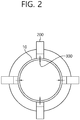
- FIG. 2 is a cross-sectional view illustrating a nuclear reactor building passive cooling system according to the present embodiment taken along line I-I' of FIG. 1 .
- a nuclear reactor building passive cooling system 100 (hereinafter, referred to as a cooling system) according to the present embodiment includes a cooling water storage reservoir 200.
- the cooling water storage reservoir 200 may be disposed in an upper area of an outer circumference of a nuclear reactor building 10.
- the cooling water storage reservoir 200 may supply cooling water to the inside of the nuclear reactor building 10, as needed, and in this case, even if main power of a reactor facility is shut off, the cooling water storage reservoir 200 may be disposed in an upper area of the nuclear reactor building 10 so as to supply cooling water by natural drop.
- a height of the cooling water storage reservoir 200 may be changed.
- the cooling water storage reservoir 200 may be disposed in the plural, FIG. 2 illustrates an embodiment in which four cooling water storage reservoirs 200 are provided, and the number of the cooling water storage reservoirs 200 is not limited thereto.
- a heat exchanger 300 is connected to the cooling water storage reservoir 200.
- One side of the heat exchanger 300 is disposed inside the cooling water storage reservoir 200 and the other side thereof is extended into the nuclear reactor building 10.
- an outflow pipe 310 and an inflow pipe 320 of the heat exchanger 300 are extended to the cooling water storage reservoir 200, and a heat exchange unit 330 is disposed inside the nuclear reactor building 10. Therefore, in the event of a cooling water spill accident, the heat exchanger 300 enables the nuclear reactor building 10 to be cooled based on cooling water stored in the cooling water storage reservoir 200.
- a steam discharging unit 340 in a pipe shape may be provided in the heat exchanger 300.
- the steam discharging unit 340 may have one end connected to an outflow pipe 310 and the other end communicating with the cooling water storage reservoir 200.
- the other end of the steam discharging unit 340 communicates with the cooling water storage reservoir 200 at a portion of a height higher than a height of cooling water contained in the cooling water storage reservoir 200.
- the steam discharging unit 340 may discharge vapor generated in the heat exchanger 300 to the atmosphere. That is, boiling may occur in the heat exchanger 300 during a heat exchange process, and the steam discharging unit 340 may discharge vapor generated in response to the boiling to the outside of the heat exchanger 300.
- the other end of the steam discharging unit 340 communicates with the inside of the cooling water storage reservoir 200.
- the cooling water stored in the cooling water storage reservoir 200 may be received while being partitioned in the cooling water storage reservoir 200.
- the cooling water storage reservoir 200 according to the present embodiment will be described in detail with reference to the accompanying drawings. However, a detailed description of the above-described constituent elements is omitted and constituent elements identical to or corresponding to those according to the foregoing embodiment are denoted by the same reference numerals.
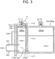
- FIG. 3 is a cross-sectional view schematically illustrating a cooling water storage reservoir of a nuclear reactor building passive cooling system according to the present embodiment
- FIG. 4 is a graph illustrating a passive alarm unit of a nuclear reactor building passive cooling system according to the present embodiment.
- FIG. 5 is a cross-sectional view illustrating a cooling water storage reservoir of a nuclear reactor building passive cooling system according to the present embodiment taken along line II-II' of FIG. 1 .
- the cooling water storage reservoir 200 includes a storage tank 200a.
- the storage tank 200a may form an outer shape of the cooling water storage reservoir 200 and may be supported to an outer wall of the nuclear reactor building 10.
- the storage tank 200a forms a space for receiving cooling water therein and may be provided in a substantially cubic shape, but a shape of the storage tank 200a is not limited thereto.
- a partition part 210 for partitioning a receiving space of the cooling water is provided at the inside of the storage tank 200a.
- the partition part 210 may be provided as a partition 210a.
- the partition 210a disposed between an upper wall and a lower wall of the storage tank 200a forms a first storage tank 200aa adjacent to the nuclear reactor building 10 and a second storage tank 200ab separated from the first storage tank 200aa.
- the heat exchanger 300 is connected to the first storage tank 200aa.
- a capacity of the second storage tank 200ab may be set to be larger than that of the first storage tank 200aa.
- a capacity of the first storage tank 200aa may be 50% or less of that of the entire storage tank 200a.
- a steam outlet H1 is formed in an upper wall of the first storage tank 200aa.
- the steam outlet H1 enables steam generating by heating cooling water of the first storage tank 200aa when cooling the nuclear reactor building 10 to be discharged to the outside. Therefore, the storage tank 200a can be prevented from being broken or damaged due to a change in an internal pressure.
- a water level reduction delay unit 220 may be installed in a steam outlet H1 may be disposed.
- the water level reduction delay unit 220 separates droplets and moisture from steam discharged from the first storage 200aa to the outside so that the separated moisture returns to the first storage tank 200aa.
- the water level reduction delay unit 220 may be provided as a moisture separator, and may delay cooling water level reduction in the storage tank 200a so as to enable passive cooling of the nuclear reactor building 10 for a long time.
- a passive alarm unit 230 may be installed above the water level reduction delay unit 220. In the case of a design basis accident and a major accident, the passive alarm unit 230 may give an alarm to perform cooling of the nuclear reactor building 10. When vapor is introduced into the steam outlet H1, the passive alarm unit 230 may generate an alarm based on vapor flow.
- the passive alarm unit 230 is provided as a passive noise generator that generates noise in response to occurrence of pressure.
- the passive alarm unit 230 may include a passive sound generating module 231 extending to the outside of the steam outlet H1.
- the sound generating module 231 may be provided in a horn shape and may generate an alarm in the surroundings when an accident occurs or a cooling operation is performed in the nuclear reactor building 10.
- the passive alarm unit 230 may be provided with various configurations enabling an alarm passively even when power is not supplied from the outside.
- the passive alarm unit 230 may include a propeller 233a disposed in the steam outlet H1.
- the propeller 233a may rotate by vapor being introduced into the steam outlet H1 in cooling of the nuclear reactor building 10, and power generated by the propeller 233a may turn on an LED module 233b disposed in the outside of the steam outlet H1.
- the passive alarm unit 230 may alarm an operation of cooling the nuclear reactor building 10 so as to primarily inform the occurrence of the cooling water leakage primarily to the surroundings, and may notify, later on, whether pressure of the nuclear reactor building 10 is increased or decreased.
- a pressure regulator H2 is formed in an upper wall of the second storage tank 200ab.
- the pressure regulator H2 maintains an internal pressure of the second storage tank 200ab to be equal to an external atmospheric pressure irrespective of an internal pressure of the first storage tank 200aa.
- Filters F1 and F2 are mounted in the steam outlet H1 and the pressure regulator H2, respectively. When the heat exchanger 300 is broken or damaged, the filters F1 and F2 prevent harmful substances, for example, radioactive materials that may be entered from the inside of the nuclear reactor building 10 into the storage tank 200a from being discharged to outer air.
- an inlet for enabling the first storage tank 200aa and the second storage tank 200ab to communicate may be provided.
- Such an inlet may be provided as a connection pipe 210aa.
- a plurality of connecting pipes 210aa may be provided.
- the plurality of connecting pipes 210aa may be disposed at the same height in order to prevent cooling water from circulating by natural convection between the first storage tank 200aa and the second storage tank 200ab.
- FIG. 5 illustrates an embodiment in which three connecting pipes 210aa are provided, but the number of the connecting pipes 210aa is not limited thereto.
- the connection pipe 210aa is disposed in the partition 210aa and thus the first storage tank 200aa and the second storage tank 200ab communicate with each other.
- a hole may be formed, except for the connection pipe 210aa, and the hole may be formed in various shapes including a circular shape and a slit.
- connection pipe 210aa forms a path that may enable cooling water received in the second storage tank 200ab to enter into the first storage tank 200aa.
- the first storage tank 200aa connected to the heat exchanger 300 quickly reaches a saturation temperature. This contributes to stabilization of a heat removal performance of the cooling system 100 and thus a temperature and pressure of the nuclear reactor building 10 are quickly stabilized.
- the reason why a capacity of the first storage tank 200aa is smaller than that of the second storage tank 200ab as described above is intended to achieve such an effect.
- the first storage tank 200aa reaches a saturation temperature, and cooling water received in the first storage tank 200aa is heated and discharged to the outside through the steam outlet H1. Therefore, a water level difference occurs between the first storage tank 200aa and the second storage tank 200ab. Therefore, cooling water in the second storage tank 200ab is entered into the first storage tank 200aa through the connection pipe 210aa so as to eliminate the water level difference.
- the cooling water storage reservoir 200 constantly maintains a heat removal performance of the cooling system 100 from the beginning of a severe accident to enable a pressure and temperature of the nuclear reactor building 10 to gradually reduce. Therefore, in a conventional cooling system, while a temperature and pressure of the nuclear reactor building 10 decrease, a heat removal performance decreases due to increase of the cooling water temperature and a problem can be solved that the pressure and temperature of the nuclear reactor building 10 is thus repressurized and reheated.
- the conventional cooling system and the cooling system 100 according to the present embodiment are compared as follows.
- FIG. 6 is a graph illustrating changes in an internal pressure and temperature of a nuclear reactor building according to use of a cooling water storage reservoir of a conventional passive cooling system
- FIG. 7 is a graph illustrating changes in an internal pressure and temperature of a nuclear reactor building according to use of a cooling water storage reservoir of a nuclear reactor building passive cooling system according to the present embodiment.
- a conventional cooling system operates with temperature and pressure rise of the nuclear reactor building 10 in the event of a cooling water spill accident.
- the conventional cooling system may reduce a temperature and pressure of the nuclear reactor building 10.
- cooling system 100 even if cooling water stored in the first storage tank 200aa is heated, cooling water received in the second storage tank 200ab is naturally entered into the first storage tank 200aa according to steam discharged to outside air. Accordingly, as shown in FIG. 7 , a temperature and pressure of the nuclear reactor building 10 are reduced smoothly in the case of a design basis accident and a major accident, and a problem can be solved that the temperature and pressure of the nuclear reactor building 10 rise again.
- the steam discharging unit 340 it is possible to drive the cooling system 100 stably, for example, minimizing flow instability due to interaction between water and steam.
- FIG. 8 is a flowchart illustrating an operation of a nuclear reactor building passive cooling system according to the present embodiment.
- the cooling system 100 may be operated in the event of a cooling water spill accident (S100).
- S100 cooling water spill accident
- steam and radioactive materials are discharged from inside the nuclear reactor building 10, thereby increasing a temperature and pressure of an inner space of the nuclear reactor building 10.
- cooling water in the heat exchange unit 330 is heated, and the heated cooling water is entered into the first storage tank 200aa.
- the cooling water received in the first storage tank 200aa is entered into the heat exchanger 300 to be provided to the heat exchange unit 330.
- the cooling system 100 repeats inflow and outflow and circulates cooling water based on a natural force (S200).
- a temperature of cooling water in the first storage tank 200aa rises to a boiling point (S300) .
- the cooling water stored in the second storage tank 200ab maintains an initial temperature.
- a time at which cooling water in the first storage tank 200aa reaches a boiling point becomes shorter than that of a conventional cooling water storage reservoir having the same capacity as that of the cooling water storage reservoir 200 according to the present embodiment. Therefore, the cooling system 100 according to the present embodiment is stabilized through a relatively short transient period.
- cooling water of the first storage tank 200aa evaporates, cooling water of a low temperature of the second storage tank 200ab is naturally entered into the first storage tank 200aa (S400). Accordingly, a heat removal performance of the cooling system 100 is lowered due to increase in a temperature of cooling water stored in the first storage tank 200aa, thereby solving a problem that a pressure and temperature of the nuclear reactor building 10 are repressurized and reheated.
- the water level reduction delay unit 220 may enable responding to a design basis accident and a major accident for a long time.
- a cooling water storage reservoir and a nuclear reactor building passive cooling system including the same can quickly stabilize a performance of the nuclear reactor building passive cooling system, thereby preventing performance deterioration of the nuclear reactor building passive cooling system.
- cooling water storage reservoir and the nuclear reactor building passive cooling system including the same can continuously reduce a pressure and temperature of the nuclear reactor building, and thus a secondary accident such as destruction of the nuclear reactor building can be suppressed from occurring.
Landscapes
- Engineering & Computer Science (AREA)
- Physics & Mathematics (AREA)
- Plasma & Fusion (AREA)
- General Engineering & Computer Science (AREA)
- High Energy & Nuclear Physics (AREA)
- Mechanical Engineering (AREA)
- General Physics & Mathematics (AREA)
- Business, Economics & Management (AREA)
- Emergency Management (AREA)
- Structure Of Emergency Protection For Nuclear Reactors (AREA)
Claims (7)
- Kernreaktor mit einem Gebäude (10) und einem Gebäude-Passivkühlsystem (100), das angrenzend an eine Außenwand des Kernreaktorgebäudes (10) angeordnet und in der Lage ist, das Kernreaktorgebäude (10) passiv zu kühlen, wobei das System (100) aufweist:ein Kühlwasserspeicherreservoir (200) mit einem Speichertank (200a), der Kühlwasser speichert;ein Unterteilungsteil (210), das im Inneren des Speichertanks (200a) angeordnet ist und das ein Inneres des Speichertanks (200a) in einen ersten Speichertank (200aa) und einen zweiten Speichertank (200ab) unterteilt, um das Kühlwasser zu trennen, und das einen Einlass (210aa) aufweist, um zu bewirken, dass das Kühlwasser des zweiten Speichertanks (200ab) auf natürliche Weise in den ersten Speichertank (200aa) gemäß einer Wasserstandsdifferenz zwischen dem ersten Speichertank (200aa) und dem zweiten Speichertank (200ab) fließt;einen Wärmetauscher (300), der sich von dem ersten Speichertank (200aa) in das Innere des Kernreaktorgebäudes (10) erstreckt und das Kernreaktorgebäude (10) basierend auf dem Kühlwasser des ersten Speichertanks (200aa) kühlt;eine Dampfabgabeeinheit (340), die mit dem Wärmetauscher (300) verbunden ist und im Wärmetauscher (300) erzeugten Dampf zur Außenseite des Wärmetauschers (300) abgibt;wobei die Dampfabgabeeinheit (340) mit einem Ende mit dem Wärmetauscher (300) und mit dem anderen Ende mit dem ersten Speichertank (200aa) in Verbindung steht;dadurch gekennzeichnet, dass
das andere Ende der Dampfabgabeeinheit (340) mit dem ersten Speichertank (200aa) an einer Position in Verbindung steht, die höher als eine Position des in dem ersten Speichertank (200aa) enthaltenen Kühlwassers ist. - Kernreaktor nach Anspruch 1, des Weiteren aufweisend:einen Dampfauslass (H1), der in dem ersten Speichertank (200aa) vorgesehen ist und einen Pfad bildet, entlang dem der in dem ersten Speichertank (200aa) erzeugte Dampf nach außen abgeleitet wird; undeine Verzögerungseinheit (220) zur Reduzierung des Wasserstands, die in dem Dampfauslass (H1) vorgesehen ist und in dem Dampf enthaltene Feuchtigkeit abscheidet, um die Verringerung eines Wasserstands des ersten Speichertanks (200aa) zu verzögern.
- Kernreaktor nach Anspruch 2, bei dem die Verzögerungseinheit (220) zur Reduzierung des Wasserstands einen Feuchtigkeitsabscheider aufweist.
- Kernreaktor nach Anspruch 2, des Weiteren aufweisend eine passive Alarmeinheit (230), die in dem Dampfauslass (H1) vorgesehen und so konfiguriert ist, dass sie den Betrieb des Wärmetauschers (300) auf der Grundlage des in den Dampfauslass (H1) eingeleiteten Dampfes alarmiert.
- Kernreaktor nach Anspruch 4, bei dem die passive Alarmeinheit (230) ein passives Schallerzeugungsmodul (231) aufweist, das so konfiguriert ist, dass es als Reaktion auf die Einleitung von Dampf in den Dampfauslass (H1) ein Geräusch erzeugt.
- Kernreaktor nach Anspruch 4, bei dem die passive Alarmeinheit (230) aufweist:einen Propeller (233a), der innerhalb des Dampfauslasses (H1) vorgesehen ist und in der Lage ist, sich in Reaktion auf in den Dampfauslass (H1) eingeleiteten Dampf zu drehen; undeine Lichtquelle (233b), die mit dem Propeller (233a) an der Außenseite des Dampfauslasses (H1) verbunden und in der Lage ist, auf der Grundlage der durch den Propeller (233a) erzeugten Energie eingeschaltet zu werden.
- Kernreaktor nach Anspruch 1, bei dem ein Fassungsvermögen des ersten Speichertanks (200aa) kleiner als ein Fassungsvermögen des zweiten Speichertanks (200ab) ist.
Applications Claiming Priority (4)
| Application Number | Priority Date | Filing Date | Title |
|---|---|---|---|
| KR1020160125738A KR101790450B1 (ko) | 2016-09-29 | 2016-09-29 | 냉각수 저장조 및 이를 포함하는 원자로건물 피동 냉각시스템 |
| KR1020160126842A KR101805316B1 (ko) | 2016-09-30 | 2016-09-30 | 냉각수 저장조 및 이를 포함하는 원자로건물 피동 냉각시스템 |
| KR1020160126849A KR101806043B1 (ko) | 2016-09-30 | 2016-09-30 | 냉각수 저장조 및 이를 포함하는 원자로건물 피동 냉각시스템 |
| PCT/KR2017/010874 WO2018062915A1 (ko) | 2016-09-29 | 2017-09-28 | 냉각수 저장조 및 이를 포함하는 원자로건물 피동 냉각시스템 |
Publications (3)
| Publication Number | Publication Date |
|---|---|
| EP3522174A1 EP3522174A1 (de) | 2019-08-07 |
| EP3522174A4 EP3522174A4 (de) | 2020-03-11 |
| EP3522174B1 true EP3522174B1 (de) | 2021-03-03 |
Family
ID=61759999
Family Applications (1)
| Application Number | Title | Priority Date | Filing Date |
|---|---|---|---|
| EP17856801.0A Active EP3522174B1 (de) | 2016-09-29 | 2017-09-28 | Kernreaktorgebäude mit passivem kühlsystem und kühlwasseraufbewahrungsreservoir dafür |
Country Status (3)
| Country | Link |
|---|---|
| US (1) | US20200043618A1 (de) |
| EP (1) | EP3522174B1 (de) |
| WO (1) | WO2018062915A1 (de) |
Family Cites Families (8)
| Publication number | Priority date | Publication date | Assignee | Title |
|---|---|---|---|---|
| JPH085772A (ja) * | 1994-06-17 | 1996-01-12 | Hitachi Ltd | 原子炉格納容器 |
| CA2150275C (en) * | 1995-05-26 | 2008-10-14 | Norman J. Spinks | Passive emergency water system for water-cooled nuclear reactors |
| JP2007170832A (ja) * | 2005-12-19 | 2007-07-05 | Toshiba Corp | 格納容器冷却装置および冷却方法 |
| KR101389276B1 (ko) * | 2012-07-13 | 2014-04-25 | 한국원자력연구원 | 원자로의 피동안전계통 |
| ES2602071T3 (es) * | 2012-07-19 | 2017-02-17 | Serbex Tecnología Y Valores, S.L. | Central nuclear, sistema de seguridad con elemento fusible y ascensor gravitacional |
| KR101447514B1 (ko) * | 2013-03-13 | 2014-10-06 | 대우조선해양 주식회사 | 해상 소형 원전용 안전 시스템 |
| KR101528223B1 (ko) * | 2014-10-01 | 2015-06-12 | 한국원자력연구원 | 피동안전설비 및 이를 구비하는 원전 |
| KR101659864B1 (ko) * | 2015-05-13 | 2016-09-26 | 한국원자력연구원 | 원전 |
-
2017
- 2017-09-28 US US16/337,718 patent/US20200043618A1/en not_active Abandoned
- 2017-09-28 WO PCT/KR2017/010874 patent/WO2018062915A1/ko not_active Ceased
- 2017-09-28 EP EP17856801.0A patent/EP3522174B1/de active Active
Non-Patent Citations (1)
| Title |
|---|
| None * |
Also Published As
| Publication number | Publication date |
|---|---|
| EP3522174A4 (de) | 2020-03-11 |
| WO2018062915A1 (ko) | 2018-04-05 |
| EP3522174A1 (de) | 2019-08-07 |
| US20200043618A1 (en) | 2020-02-06 |
Similar Documents
| Publication | Publication Date | Title |
|---|---|---|
| KR102075101B1 (ko) | 냉각 구조가 개선된 배터리 팩 | |
| US10811148B2 (en) | Self-diagnosis and accident-handling unmanned nuclear reactor | |
| KR101832067B1 (ko) | 냉각수 저장조 및 이를 포함하는 원자로건물 피동 냉각시스템 | |
| KR20110106850A (ko) | 반응로 용기 냉각제 편향 차폐부 | |
| CN107636769B (zh) | 核反应堆、尤其是紧凑型的液态金属冷却核反应堆 | |
| CN114171217A (zh) | 抑压水池装置及核反应堆 | |
| US10249393B2 (en) | Modular reactor steam generator configured to cover a reactor outer wall circumference | |
| KR101806043B1 (ko) | 냉각수 저장조 및 이를 포함하는 원자로건물 피동 냉각시스템 | |
| EP3506319B1 (de) | Kühlwasserspeicher und passives kühlsystem für ein kernreaktorgebäude damit | |
| JP2020023965A (ja) | 車両の冷却システム | |
| EP3522174A1 (de) | Kühlwasseraufbewahrungsreservoir und passives kühlsystem für kernreaktorgebäude damit | |
| WO2014112408A1 (ja) | 湿分分離加熱器、及びこれを備える湿分分離加熱設備 | |
| EP3522175B1 (de) | Passives sicherheitsbehälterkühlsystem mit einem kühlmittelbehälter | |
| KR101790450B1 (ko) | 냉각수 저장조 및 이를 포함하는 원자로건물 피동 냉각시스템 | |
| KR101790451B1 (ko) | 냉각수 충수 시스템 및 이를 포함하는 원자로건물 피동 냉각시스템 | |
| JPH0659076A (ja) | 加圧水型原子炉の残留出力除去装置 | |
| EP3522176A1 (de) | Kühlwasserspeicher und passives kühlsystem damit für ein reaktorsicherheitsgebäude | |
| KR102180187B1 (ko) | 증기 방출 노즐 및 이를 포함하는 증기 방출 시스템 | |
| KR101805316B1 (ko) | 냉각수 저장조 및 이를 포함하는 원자로건물 피동 냉각시스템 | |
| EP3492811B1 (de) | Kernkraftwerke | |
| KR20180036656A (ko) | 냉각수 저장조 및 이를 포함하는 원자로건물 피동 냉각시스템 | |
| KR20180036641A (ko) | 냉각수 저장조 및 이를 포함하는 원자로건물 피동 냉각시스템 | |
| KR102643953B1 (ko) | 일체형원자로 피동냉각장치 | |
| KR102458247B1 (ko) | 원자로의 피동냉각 설비 및 그의 피동냉각 방법 | |
| KR20120125012A (ko) | 원자로 |
Legal Events
| Date | Code | Title | Description |
|---|---|---|---|
| STAA | Information on the status of an ep patent application or granted ep patent |
Free format text: STATUS: THE INTERNATIONAL PUBLICATION HAS BEEN MADE |
|
| PUAI | Public reference made under article 153(3) epc to a published international application that has entered the european phase |
Free format text: ORIGINAL CODE: 0009012 |
|
| STAA | Information on the status of an ep patent application or granted ep patent |
Free format text: STATUS: REQUEST FOR EXAMINATION WAS MADE |
|
| 17P | Request for examination filed |
Effective date: 20190327 |
|
| AK | Designated contracting states |
Kind code of ref document: A1 Designated state(s): AL AT BE BG CH CY CZ DE DK EE ES FI FR GB GR HR HU IE IS IT LI LT LU LV MC MK MT NL NO PL PT RO RS SE SI SK SM TR |
|
| AX | Request for extension of the european patent |
Extension state: BA ME |
|
| RIN1 | Information on inventor provided before grant (corrected) |
Inventor name: LIM, SANG GYU Inventor name: KIM, DAE HUN Inventor name: KIM, HAN GON Inventor name: HEO, SUN Inventor name: YOON, BYOUNG JO Inventor name: HA, HUI UN Inventor name: CHEON, JONG Inventor name: LEE, SANG WON |
|
| DAV | Request for validation of the european patent (deleted) | ||
| DAX | Request for extension of the european patent (deleted) | ||
| A4 | Supplementary search report drawn up and despatched |
Effective date: 20200207 |
|
| RIC1 | Information provided on ipc code assigned before grant |
Ipc: G21C 13/02 20060101ALI20200203BHEP Ipc: G08B 21/18 20060101ALI20200203BHEP Ipc: B65D 90/52 20060101ALI20200203BHEP Ipc: G21C 17/032 20060101ALI20200203BHEP Ipc: B65D 90/00 20060101ALI20200203BHEP Ipc: G21C 9/012 20060101AFI20200203BHEP Ipc: B65D 88/02 20060101ALI20200203BHEP Ipc: B65D 90/32 20060101ALI20200203BHEP Ipc: G21C 15/18 20060101ALI20200203BHEP |
|
| REG | Reference to a national code |
Ref country code: DE Ref legal event code: R079 Ref document number: 602017034070 Country of ref document: DE Free format text: PREVIOUS MAIN CLASS: G21C0015180000 Ipc: G21C0009012000 |
|
| GRAP | Despatch of communication of intention to grant a patent |
Free format text: ORIGINAL CODE: EPIDOSNIGR1 |
|
| STAA | Information on the status of an ep patent application or granted ep patent |
Free format text: STATUS: GRANT OF PATENT IS INTENDED |
|
| RIC1 | Information provided on ipc code assigned before grant |
Ipc: G21C 17/032 20060101ALI20200916BHEP Ipc: G21C 13/02 20060101ALI20200916BHEP Ipc: B65D 90/00 20060101ALI20200916BHEP Ipc: B65D 90/52 20060101ALI20200916BHEP Ipc: G08B 21/18 20060101ALI20200916BHEP Ipc: G21C 9/012 20060101AFI20200916BHEP Ipc: B65D 90/32 20060101ALI20200916BHEP Ipc: G21C 15/18 20060101ALI20200916BHEP Ipc: B65D 88/02 20060101ALI20200916BHEP |
|
| INTG | Intention to grant announced |
Effective date: 20201006 |
|
| GRAS | Grant fee paid |
Free format text: ORIGINAL CODE: EPIDOSNIGR3 |
|
| GRAA | (expected) grant |
Free format text: ORIGINAL CODE: 0009210 |
|
| STAA | Information on the status of an ep patent application or granted ep patent |
Free format text: STATUS: THE PATENT HAS BEEN GRANTED |
|
| AK | Designated contracting states |
Kind code of ref document: B1 Designated state(s): AL AT BE BG CH CY CZ DE DK EE ES FI FR GB GR HR HU IE IS IT LI LT LU LV MC MK MT NL NO PL PT RO RS SE SI SK SM TR |
|
| REG | Reference to a national code |
Ref country code: GB Ref legal event code: FG4D |
|
| REG | Reference to a national code |
Ref country code: AT Ref legal event code: REF Ref document number: 1368092 Country of ref document: AT Kind code of ref document: T Effective date: 20210315 Ref country code: CH Ref legal event code: EP |
|
| REG | Reference to a national code |
Ref country code: DE Ref legal event code: R096 Ref document number: 602017034070 Country of ref document: DE |
|
| REG | Reference to a national code |
Ref country code: IE Ref legal event code: FG4D |
|
| REG | Reference to a national code |
Ref country code: FI Ref legal event code: FGE |
|
| REG | Reference to a national code |
Ref country code: LT Ref legal event code: MG9D |
|
| PG25 | Lapsed in a contracting state [announced via postgrant information from national office to epo] |
Ref country code: LT Free format text: LAPSE BECAUSE OF FAILURE TO SUBMIT A TRANSLATION OF THE DESCRIPTION OR TO PAY THE FEE WITHIN THE PRESCRIBED TIME-LIMIT Effective date: 20210303 Ref country code: BG Free format text: LAPSE BECAUSE OF FAILURE TO SUBMIT A TRANSLATION OF THE DESCRIPTION OR TO PAY THE FEE WITHIN THE PRESCRIBED TIME-LIMIT Effective date: 20210603 Ref country code: NO Free format text: LAPSE BECAUSE OF FAILURE TO SUBMIT A TRANSLATION OF THE DESCRIPTION OR TO PAY THE FEE WITHIN THE PRESCRIBED TIME-LIMIT Effective date: 20210603 Ref country code: HR Free format text: LAPSE BECAUSE OF FAILURE TO SUBMIT A TRANSLATION OF THE DESCRIPTION OR TO PAY THE FEE WITHIN THE PRESCRIBED TIME-LIMIT Effective date: 20210303 Ref country code: GR Free format text: LAPSE BECAUSE OF FAILURE TO SUBMIT A TRANSLATION OF THE DESCRIPTION OR TO PAY THE FEE WITHIN THE PRESCRIBED TIME-LIMIT Effective date: 20210604 |
|
| REG | Reference to a national code |
Ref country code: NL Ref legal event code: MP Effective date: 20210303 |
|
| REG | Reference to a national code |
Ref country code: AT Ref legal event code: MK05 Ref document number: 1368092 Country of ref document: AT Kind code of ref document: T Effective date: 20210303 |
|
| PG25 | Lapsed in a contracting state [announced via postgrant information from national office to epo] |
Ref country code: LV Free format text: LAPSE BECAUSE OF FAILURE TO SUBMIT A TRANSLATION OF THE DESCRIPTION OR TO PAY THE FEE WITHIN THE PRESCRIBED TIME-LIMIT Effective date: 20210303 Ref country code: RS Free format text: LAPSE BECAUSE OF FAILURE TO SUBMIT A TRANSLATION OF THE DESCRIPTION OR TO PAY THE FEE WITHIN THE PRESCRIBED TIME-LIMIT Effective date: 20210303 Ref country code: PL Free format text: LAPSE BECAUSE OF FAILURE TO SUBMIT A TRANSLATION OF THE DESCRIPTION OR TO PAY THE FEE WITHIN THE PRESCRIBED TIME-LIMIT Effective date: 20210303 Ref country code: SE Free format text: LAPSE BECAUSE OF FAILURE TO SUBMIT A TRANSLATION OF THE DESCRIPTION OR TO PAY THE FEE WITHIN THE PRESCRIBED TIME-LIMIT Effective date: 20210303 |
|
| PG25 | Lapsed in a contracting state [announced via postgrant information from national office to epo] |
Ref country code: NL Free format text: LAPSE BECAUSE OF FAILURE TO SUBMIT A TRANSLATION OF THE DESCRIPTION OR TO PAY THE FEE WITHIN THE PRESCRIBED TIME-LIMIT Effective date: 20210303 |
|
| PG25 | Lapsed in a contracting state [announced via postgrant information from national office to epo] |
Ref country code: EE Free format text: LAPSE BECAUSE OF FAILURE TO SUBMIT A TRANSLATION OF THE DESCRIPTION OR TO PAY THE FEE WITHIN THE PRESCRIBED TIME-LIMIT Effective date: 20210303 Ref country code: AT Free format text: LAPSE BECAUSE OF FAILURE TO SUBMIT A TRANSLATION OF THE DESCRIPTION OR TO PAY THE FEE WITHIN THE PRESCRIBED TIME-LIMIT Effective date: 20210303 Ref country code: SM Free format text: LAPSE BECAUSE OF FAILURE TO SUBMIT A TRANSLATION OF THE DESCRIPTION OR TO PAY THE FEE WITHIN THE PRESCRIBED TIME-LIMIT Effective date: 20210303 |
|
| PG25 | Lapsed in a contracting state [announced via postgrant information from national office to epo] |
Ref country code: PT Free format text: LAPSE BECAUSE OF FAILURE TO SUBMIT A TRANSLATION OF THE DESCRIPTION OR TO PAY THE FEE WITHIN THE PRESCRIBED TIME-LIMIT Effective date: 20210705 Ref country code: SK Free format text: LAPSE BECAUSE OF FAILURE TO SUBMIT A TRANSLATION OF THE DESCRIPTION OR TO PAY THE FEE WITHIN THE PRESCRIBED TIME-LIMIT Effective date: 20210303 Ref country code: RO Free format text: LAPSE BECAUSE OF FAILURE TO SUBMIT A TRANSLATION OF THE DESCRIPTION OR TO PAY THE FEE WITHIN THE PRESCRIBED TIME-LIMIT Effective date: 20210303 Ref country code: IS Free format text: LAPSE BECAUSE OF FAILURE TO SUBMIT A TRANSLATION OF THE DESCRIPTION OR TO PAY THE FEE WITHIN THE PRESCRIBED TIME-LIMIT Effective date: 20210703 |
|
| REG | Reference to a national code |
Ref country code: DE Ref legal event code: R097 Ref document number: 602017034070 Country of ref document: DE |
|
| PLBE | No opposition filed within time limit |
Free format text: ORIGINAL CODE: 0009261 |
|
| STAA | Information on the status of an ep patent application or granted ep patent |
Free format text: STATUS: NO OPPOSITION FILED WITHIN TIME LIMIT |
|
| PG25 | Lapsed in a contracting state [announced via postgrant information from national office to epo] |
Ref country code: DK Free format text: LAPSE BECAUSE OF FAILURE TO SUBMIT A TRANSLATION OF THE DESCRIPTION OR TO PAY THE FEE WITHIN THE PRESCRIBED TIME-LIMIT Effective date: 20210303 Ref country code: AL Free format text: LAPSE BECAUSE OF FAILURE TO SUBMIT A TRANSLATION OF THE DESCRIPTION OR TO PAY THE FEE WITHIN THE PRESCRIBED TIME-LIMIT Effective date: 20210303 Ref country code: ES Free format text: LAPSE BECAUSE OF FAILURE TO SUBMIT A TRANSLATION OF THE DESCRIPTION OR TO PAY THE FEE WITHIN THE PRESCRIBED TIME-LIMIT Effective date: 20210303 |
|
| 26N | No opposition filed |
Effective date: 20211206 |
|
| PG25 | Lapsed in a contracting state [announced via postgrant information from national office to epo] |
Ref country code: SI Free format text: LAPSE BECAUSE OF FAILURE TO SUBMIT A TRANSLATION OF THE DESCRIPTION OR TO PAY THE FEE WITHIN THE PRESCRIBED TIME-LIMIT Effective date: 20210303 |
|
| REG | Reference to a national code |
Ref country code: DE Ref legal event code: R119 Ref document number: 602017034070 Country of ref document: DE |
|
| PG25 | Lapsed in a contracting state [announced via postgrant information from national office to epo] |
Ref country code: IT Free format text: LAPSE BECAUSE OF FAILURE TO SUBMIT A TRANSLATION OF THE DESCRIPTION OR TO PAY THE FEE WITHIN THE PRESCRIBED TIME-LIMIT Effective date: 20210303 |
|
| REG | Reference to a national code |
Ref country code: CH Ref legal event code: PL |
|
| REG | Reference to a national code |
Ref country code: BE Ref legal event code: MM Effective date: 20210930 |
|
| PG25 | Lapsed in a contracting state [announced via postgrant information from national office to epo] |
Ref country code: IS Free format text: LAPSE BECAUSE OF FAILURE TO SUBMIT A TRANSLATION OF THE DESCRIPTION OR TO PAY THE FEE WITHIN THE PRESCRIBED TIME-LIMIT Effective date: 20210703 Ref country code: MC Free format text: LAPSE BECAUSE OF FAILURE TO SUBMIT A TRANSLATION OF THE DESCRIPTION OR TO PAY THE FEE WITHIN THE PRESCRIBED TIME-LIMIT Effective date: 20210303 |
|
| PG25 | Lapsed in a contracting state [announced via postgrant information from national office to epo] |
Ref country code: LU Free format text: LAPSE BECAUSE OF NON-PAYMENT OF DUE FEES Effective date: 20210928 Ref country code: IE Free format text: LAPSE BECAUSE OF NON-PAYMENT OF DUE FEES Effective date: 20210928 Ref country code: DE Free format text: LAPSE BECAUSE OF NON-PAYMENT OF DUE FEES Effective date: 20220401 Ref country code: BE Free format text: LAPSE BECAUSE OF NON-PAYMENT OF DUE FEES Effective date: 20210930 |
|
| PG25 | Lapsed in a contracting state [announced via postgrant information from national office to epo] |
Ref country code: LI Free format text: LAPSE BECAUSE OF NON-PAYMENT OF DUE FEES Effective date: 20210930 Ref country code: CH Free format text: LAPSE BECAUSE OF NON-PAYMENT OF DUE FEES Effective date: 20210930 |
|
| PG25 | Lapsed in a contracting state [announced via postgrant information from national office to epo] |
Ref country code: CY Free format text: LAPSE BECAUSE OF FAILURE TO SUBMIT A TRANSLATION OF THE DESCRIPTION OR TO PAY THE FEE WITHIN THE PRESCRIBED TIME-LIMIT Effective date: 20210303 |
|
| PG25 | Lapsed in a contracting state [announced via postgrant information from national office to epo] |
Ref country code: HU Free format text: LAPSE BECAUSE OF FAILURE TO SUBMIT A TRANSLATION OF THE DESCRIPTION OR TO PAY THE FEE WITHIN THE PRESCRIBED TIME-LIMIT; INVALID AB INITIO Effective date: 20170928 |
|
| PG25 | Lapsed in a contracting state [announced via postgrant information from national office to epo] |
Ref country code: MK Free format text: LAPSE BECAUSE OF FAILURE TO SUBMIT A TRANSLATION OF THE DESCRIPTION OR TO PAY THE FEE WITHIN THE PRESCRIBED TIME-LIMIT Effective date: 20210303 |
|
| PG25 | Lapsed in a contracting state [announced via postgrant information from national office to epo] |
Ref country code: TR Free format text: LAPSE BECAUSE OF FAILURE TO SUBMIT A TRANSLATION OF THE DESCRIPTION OR TO PAY THE FEE WITHIN THE PRESCRIBED TIME-LIMIT Effective date: 20210303 |
|
| PG25 | Lapsed in a contracting state [announced via postgrant information from national office to epo] |
Ref country code: MT Free format text: LAPSE BECAUSE OF FAILURE TO SUBMIT A TRANSLATION OF THE DESCRIPTION OR TO PAY THE FEE WITHIN THE PRESCRIBED TIME-LIMIT Effective date: 20210303 |
|
| PGFP | Annual fee paid to national office [announced via postgrant information from national office to epo] |
Ref country code: FI Payment date: 20250922 Year of fee payment: 9 |
|
| PGFP | Annual fee paid to national office [announced via postgrant information from national office to epo] |
Ref country code: GB Payment date: 20250813 Year of fee payment: 9 |
|
| PGFP | Annual fee paid to national office [announced via postgrant information from national office to epo] |
Ref country code: FR Payment date: 20250813 Year of fee payment: 9 |
|
| PGFP | Annual fee paid to national office [announced via postgrant information from national office to epo] |
Ref country code: CZ Payment date: 20250813 Year of fee payment: 9 |