EP3522141B1 - Linsenförmiger anzeigekörper, verfahren zur herstellung eines linsenförmigen bildes, verfahren zur herstellung eines linsenförmigen anzeigekörpers und programm zur bildung eines linsenförmigen bildes - Google Patents
Linsenförmiger anzeigekörper, verfahren zur herstellung eines linsenförmigen bildes, verfahren zur herstellung eines linsenförmigen anzeigekörpers und programm zur bildung eines linsenförmigen bildes Download PDFInfo
- Publication number
- EP3522141B1 EP3522141B1 EP17855664.3A EP17855664A EP3522141B1 EP 3522141 B1 EP3522141 B1 EP 3522141B1 EP 17855664 A EP17855664 A EP 17855664A EP 3522141 B1 EP3522141 B1 EP 3522141B1
- Authority
- EP
- European Patent Office
- Prior art keywords
- image
- lenticular
- display
- color
- main
- Prior art date
- Legal status (The legal status is an assumption and is not a legal conclusion. Google has not performed a legal analysis and makes no representation as to the accuracy of the status listed.)
- Active
Links
Images


Classifications
-
- G—PHYSICS
- G02—OPTICS
- G02B—OPTICAL ELEMENTS, SYSTEMS OR APPARATUS
- G02B30/00—Optical systems or apparatus for producing three-dimensional [3D] effects, e.g. stereoscopic images
- G02B30/20—Optical systems or apparatus for producing three-dimensional [3D] effects, e.g. stereoscopic images by providing first and second parallax images to an observer's left and right eyes
- G02B30/26—Optical systems or apparatus for producing three-dimensional [3D] effects, e.g. stereoscopic images by providing first and second parallax images to an observer's left and right eyes of the autostereoscopic type
- G02B30/27—Optical systems or apparatus for producing three-dimensional [3D] effects, e.g. stereoscopic images by providing first and second parallax images to an observer's left and right eyes of the autostereoscopic type involving lenticular arrays
-
- G—PHYSICS
- G02—OPTICS
- G02B—OPTICAL ELEMENTS, SYSTEMS OR APPARATUS
- G02B3/00—Simple or compound lenses
- G02B3/0006—Arrays
- G02B3/0037—Arrays characterized by the distribution or form of lenses
- G02B3/005—Arrays characterized by the distribution or form of lenses arranged along a single direction only, e.g. lenticular sheets
-
- G—PHYSICS
- G02—OPTICS
- G02B—OPTICAL ELEMENTS, SYSTEMS OR APPARATUS
- G02B3/00—Simple or compound lenses
- G02B3/02—Simple or compound lenses with non-spherical faces
- G02B3/06—Simple or compound lenses with non-spherical faces with cylindrical or toric faces
-
- G—PHYSICS
- G03—PHOTOGRAPHY; CINEMATOGRAPHY; ANALOGOUS TECHNIQUES USING WAVES OTHER THAN OPTICAL WAVES; ELECTROGRAPHY; HOLOGRAPHY
- G03B—APPARATUS OR ARRANGEMENTS FOR TAKING PHOTOGRAPHS OR FOR PROJECTING OR VIEWING THEM; APPARATUS OR ARRANGEMENTS EMPLOYING ANALOGOUS TECHNIQUES USING WAVES OTHER THAN OPTICAL WAVES; ACCESSORIES THEREFOR
- G03B25/00—Viewers, other than projection viewers, giving motion-picture effects by persistence of vision, e.g. zoetrope
- G03B25/02—Viewers, other than projection viewers, giving motion-picture effects by persistence of vision, e.g. zoetrope with interposed lenticular or line screen
-
- G—PHYSICS
- G03—PHOTOGRAPHY; CINEMATOGRAPHY; ANALOGOUS TECHNIQUES USING WAVES OTHER THAN OPTICAL WAVES; ELECTROGRAPHY; HOLOGRAPHY
- G03B—APPARATUS OR ARRANGEMENTS FOR TAKING PHOTOGRAPHS OR FOR PROJECTING OR VIEWING THEM; APPARATUS OR ARRANGEMENTS EMPLOYING ANALOGOUS TECHNIQUES USING WAVES OTHER THAN OPTICAL WAVES; ACCESSORIES THEREFOR
- G03B35/00—Stereoscopic photography
-
- G—PHYSICS
- G09—EDUCATION; CRYPTOGRAPHY; DISPLAY; ADVERTISING; SEALS
- G09F—DISPLAYING; ADVERTISING; SIGNS; LABELS OR NAME-PLATES; SEALS
- G09F19/00—Advertising or display means not otherwise provided for
- G09F19/12—Advertising or display means not otherwise provided for using special optical effects
- G09F19/125—Stereoscopic displays; 3D displays
-
- G—PHYSICS
- G09—EDUCATION; CRYPTOGRAPHY; DISPLAY; ADVERTISING; SEALS
- G09F—DISPLAYING; ADVERTISING; SIGNS; LABELS OR NAME-PLATES; SEALS
- G09F19/00—Advertising or display means not otherwise provided for
- G09F19/12—Advertising or display means not otherwise provided for using special optical effects
- G09F19/14—Advertising or display means not otherwise provided for using special optical effects displaying different signs depending upon the view-point of the observer
-
- H—ELECTRICITY
- H04—ELECTRIC COMMUNICATION TECHNIQUE
- H04N—PICTORIAL COMMUNICATION, e.g. TELEVISION
- H04N13/00—Stereoscopic video systems; Multi-view video systems; Details thereof
- H04N13/30—Image reproducers
- H04N13/302—Image reproducers for viewing without the aid of special glasses, i.e. using autostereoscopic displays
- H04N13/305—Image reproducers for viewing without the aid of special glasses, i.e. using autostereoscopic displays using lenticular lenses, e.g. arrangements of cylindrical lenses
Definitions
- the present disclosure relates to a lenticular display, a method for manufacturing a lenticular display, and a data carrier with a program for forming a lenticular image stored thereon.
- a lenticular display has been known as a medium that displays different images depending on a viewing angle.
- a lenticular lens is used in which convex lenses are arranged side by side, and the convex lenses each have a convex surface.
- image strips obtained by combining a plurality of images that are interlaced are arranged on a back-face side (facing away from the surface of the convex lenses) of the lenticular lens.
- image strips are observed through the lenticular lens, one type or two or more types of images among the image strips are displayed depending on an observing angle.
- a lenticular display 100 has a lenticular lens 104 in which a plurality of convex lenses 102 each having a convex surface are arranged side by side.
- display image strips An and Bn (hereinafter also referred to as "image strips An and Bn") for displaying display images A and B, respectively, are arranged side by side at corresponding positions so that the display images A and B are switched depending on a viewing angle.
- a lenticular image 106 is constituted by the image strips An and Bn.
- the lenticular display 100 includes the lenticular lens 104 in which, for example, N (N is an integer of 2 or more) convex lenses 102 are arranged side by side
- N is an integer of 2 or more
- convex lens 102 counting from one end in a direction in which the convex lenses 102 are arranged side by side
- an image strip An and an image strip Bn are arranged side by side to be adjacent to each other in an interlaced manner as illustrated in Fig. 7 .
- the image strips An and Bn are extracted by dividing the images A and B in a stripe form.
- the image strips An and Bn extracted from the images A and B, respectively are arranged side by side at corresponding positions. Furthermore, a changing effect is obtained in which, depending on an angle at which an observer views the lenticular display 100 through the lenticular lens 104, the image A is displayed as a result of combination of the image strips An extracted from the image A, or the image B is displayed as a result of combination of the image strips Bn extracted from the image B.
- JP1999-212024A JP-H11-212024A
- JP-H11-212024A describes a technique for suppressing the generation of crosstalk by providing, in image display using the lenticular lens, a buffering region between compressed images (display image strips).
- the buffering region is an image having an intermediate density of the densities of the compressed images that are adjacent to each other.
- JP2000-98948A describes a technique for arranging, in a display device for image display using a lenticular sheet, an image obtained by extracting a part with no change in image in the arrangement of the lenticular image in order to reduce the crosstalk.
- JP 411212024A discloses an image display method of an image display device constituted so that a compressed image formed on an image sheet is observed through a lenticular screen consisting of lenticular lenses and a beltlike buffer area is provided between adjacent compressed images formed on the image sheet corresponding to one lenticular lens; when the adjacent compressed images are observed through the lenticular screen at a viewpoint position changing continuously, two images of those compressed images are observed while separated from each other because of the presence of the buffer area.
- US 2009/0167639 A1 discloses methods of reducing perceived image crosstalk in a Multiview display.
- One method includes providing an image stream to a display having a horizontal dimension that extends from a first side of the display to an opposing second side of the display.
- the image stream includes a temporal sequence of images where at least a first image view and then a second image view are displayed on the display in a time sequential manner.
- the temporal sequence of images are conditioned before being displayed in order to reduce perceived displayed image crosstalk between the first and second image views.
- the conditioning includes modifying a color intensity of at least selected pixels along the horizontal dimension based on a non-constant crosstalk correction function for the horizontal dimension.
- the crosstalk is not sufficiently suppressed, and an afterimage that interrupts viewing is generated when a viewed image is switched.
- the present disclosure provides a lenticular display, a method for manufacturing a lenticular display, and a program for forming a lenticular image that can reduce the feeling of afterimage at the time a viewed image is switched.
- a lenticular display according to the present invention is defined by claim 1.
- the lenticular display comprises: a lenticular lens in which a plurality of convex lenses are arranged side by side, the plurality of convex lenses each having a convex surface; and a lenticular image provided on a back-face side facing away from the surface of the convex lenses, in which the lenticular image is a plurality of display image strips that are extracted from each of a plurality of display images in a stripe form and are arranged at corresponding positions under the convex lenses, and in which, in the plurality of display images, a color density of a portion where main-image parts overlap with each other is corrected.
- Each of the plurality of display images has a main image part and a background image part, and the color density of the portion where the main-image parts overlap with each other may be corrected to an intermediate color of a color of the main image part and a color of the background image part.
- the color density of the intermediate color may be greater than or equal to 5 % and less than 50 % of the color density of the background image part.
- the main image part may include at least one of a picture or a character.
- a method for forming a lenticular display according to the present invention is defined by claim 4.
- the method includes the steps of: correcting, for each of a plurality of display images, a color density of a portion where main-image parts overlap with each other; extracting a plurality of display image strips in a stripe form from each of the plurality of display images whose color density has been corrected; and generating image strips in which the plurality of display image strips are arranged to be adjacent to each other at corresponding positions.
- Each of the plurality of display images has a main image part and a background image part, and the color density of the portion where the main-image parts overlap with each is corrected to an intermediate color of a color of the main image part and a color of the background image part.
- the main image part may include at least one of a picture or a character.
- a method for manufacturing a lenticular display according to the present invention has a step of forming a lenticular image by the method for forming a lenticular image according to the present invention on a surface of a recording medium; and a step of bonding the surface of the recording medium on which the lenticular image is formed and a back face of a lenticular lens in which a plurality of convex lenses are arranged side by side, the plurality of convex lenses each having a convex surface, the back face facing away from the surface.
- the method has a step of forming a lenticular image by the method for forming a lenticular image on a back face of a lenticular lens in which a plurality of convex lenses are arranged side by side, the plurality of convex lenses each having a convex surface, the back face facing away from the surface.
- a data carrier according to the present invention is defined by claim 8.
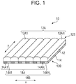
- x-direction represents a width direction of the lenticular display 10
- y-direction represents a length direction (longitudinal direction) of the lenticular display 10.
- the lenticular display 10 includes a lenticular lens 12 and a lenticular image 14.
- a plurality of convex lenses 12A (12A1 to 12AN, N is an integer of 2 or more and is 6 in the case illustrated in Fig. 1 ) are arranged side by side.
- the convex lenses 12A are each a cylindrical lens whose shape is substantially semi-cylindrical having a convex surface 12S (top face in Fig. 1 ), which is spherical, and a back face 12B (bottom face in Fig. 1 ) facing away from the surface 12S, and are arranged side by side in the width direction (x-direction).
- the lenticular lens 12, that is, the convex lenses 12A, is formed of a resin material having a light transmitting property.
- the resin that constitutes the lenticular lens 12 include polymethylmethacrylate (PMMA), polycarbonate, polystyrene, methacrylate-styrene copolymer (MS resin), acrylonitrile-styrene copolymer (AS resin), polypropylene, polyethylene, polyethylene terephthalate (PET), glycol-modified PET, polyvinyl chloride (PVC), thermoplastic elastomer, copolymer of these, cyclo olefin polymer, and the like.
- PMMA polymethylmethacrylate
- MS resin methacrylate-styrene copolymer
- AS resin acrylonitrile-styrene copolymer
- PMMA polymethylmethacrylate
- MS resin methacrylate-styrene copolymer
- AS resin acrylon
- a resin with a low melt temperature such as PMMA, polycarbonate, polystyrene, MS resin, polyethylene, PET, or glycol-modified PET. Since a lens shape formed on a surface of an embossing roller is easily transferred and a crack is unlikely to be generated in a lens layer at the time of embossing, it is more preferable to use glycol-modified PET.
- the lenticular lens 12 may also be configured to include a plurality of resins.
- a width of each of the convex lenses 12A is preferably greater than or equal to 50 ⁇ m and less than or equal to 900 ⁇ m for processability and a resolution of images.
- the lens pitch can be set as appropriate in accordance with the use of the lenticular display. For example, in a case where an observer observes the lenticular display by holding it, the lens pitch is preferably greater than or equal to 100 ⁇ m and less than or equal to 450 ⁇ m. This is because, in a case where the lenticular display is observed from a relatively short distance, the boundary between lenses becomes less jaggy, so that characters and the like are less difficult to read, when the lens pitch is not too large.
- the lens pitch is preferably greater than or equal to 200 ⁇ m and less than or equal to 850 ⁇ m, for example.
- the lens pitch may be defined by LPI (Line Per Inch, the number of lenses per 1 inch (2.54 cm)) and may preferably be 100 LPI, 200 LPI, or the like, for example.
- LPI Line Per Inch, the number of lenses per 1 inch (2.54 cm)
- the lenticular image 14 is provided on a back-face side of the convex lenses 12A, that is, on the back face 12B side of the lenticular lens 12, the lenticular image 14 is provided.
- the lenticular image 14 is constituted by image strips including display image strips 14A1 to 14AN and 14B1 to 14BN for displaying two display images 13A and 13B separately.
- the display image strips 14A1 to 14AN and 14B1 to 14BN extracted in a stripe form from the display images 13A and 13B, respectively, are arranged to be adjacent to each other for each of the convex lenses 12A at corresponding positions.
- the "display image” in this embodiment means an image that is aimed to be displayed by the lenticular display 10, that is, an image that is aimed to be recognized by an observer when the observer observes the lenticular display 10 from the lenticular lens 12 side.
- the "display image strip” means a rectangular image that is arranged in parallel to y-direction of the lenticular lens 12 under the lenticular lens 12 and that constitutes a part of the display images 13A and 13B.
- display image 13 is used for collectively referring to the display images 13A and 13B without distinguishing one from the other.
- display image strip 14A is used for collectively referring to the display image strips 14A1 to 14AN without distinguishing one from another
- display image strip 14B is used for collectively referring to the display image strips 14B1 to 14BN without distinguishing one from another.
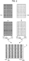
- Fig. 3 illustrates an example of the display images 13A and 13B according to this embodiment. Note that in the example illustrated in Fig. 3 , a case where a pictogram is a displayed image is illustrated. Note that the "pictogram" in this embodiment is an example of a "picture” in the present disclosure.
- the display image 13A according to this embodiment includes two main-image parts 13Am1 and 13Am2 and a single background-image part 13Ab.
- the display image 13B according to this embodiment includes two main-image parts 13Bm1 and 13Bm2 and a single background-image part 13Bb.
- main image color a color of the main-image parts 13Am1, 13Am2, 13Bm1, and 13Bm2
- background image color a color of the background-image parts 13Ab and 13Bb
- the "main-image part” means a part of the display image 13 that is viewed as if being switched when an observer observes the lenticular display 10 by changing the angle.
- the "background-image part” means a part of the display image 13 that is viewed as not being switched when the observer observes the lenticular display 10 by changing the angle and means a part other than the main-image part in this embodiment.
- a color density at a portion where the main-image parts overlap with each other is corrected. Note that in an upper drawing in Fig. 3 , for each of the display images 13A and 13B, display images 113A and 113B before correction of the color density in the overlap portion (before color density correction) are illustrated.
- the "portion where the main-image parts overlap with each other” means a portion where the main-image parts overlap when the display image 13A and the display image 13B overlap with each other.
- portions where the main-image parts overlap with each other are arranged adjacent to each other in a case of constituting the lenticular image 14.
- the portion where the main-image parts overlap with each other is a portion where the main-image part 13Am1 and the main-image part 13Bm1 overlap with each other, and a portion where the main-image part 13Am2 and the main-image part 13Bm2 overlap with each other.
- the portion where the main-image parts overlap with each other is an image of a portion where an arrow image that is the main-image part 13Am1 and an arrow image that is the main-image part 13Bm1 overlap with each other, and an image of a portion where a pictogram image representing an elevator that is the main-image part 13Am2 and a pictogram image representing stairs that is the main-image part 13Bm2 overlap with each other.
- the portion where the main-image parts of the display image 13A and the main-image parts of the display image 13B overlap with each other is likely to be viewed as an afterimage because a color density is increased by the overlap of the main-image parts. Accordingly, in this embodiment, in order to suppress the afterimage and to make it easier to view the main-image parts even if the afterimage is generated, the color density of the portion where main-image parts of the display image 13A and the main-image parts of the display image 13B overlap with each other is corrected.
- the color density of the portion where the main-image part 13Am1 and the main-image parts 13Bm1 overlap with each other is corrected by using grey, which is an intermediate color of the main image color of the main-image parts 13Am1 and 13Bm1 and the background image color of the background-image parts 13Ab and 13Bb.
- the color density of the portion where the main-image part 13Am2 and the main-image parts 13Bm2 overlap with each other is corrected by using grey, which is an intermediate color of the main image color of the main-image parts 13Am2 and 13Bm2 and the background image color of the background-image parts 13Ab and 13Bb.
- the lenticular image 14 according to this embodiment is formed by an image forming apparatus 30, an example of which is illustrated in Fig. 4 .
- the image forming apparatus 30 may be a microcomputer or the like including a control unit 32, a storage unit 34, and an I/F (Interface) unit 36.
- the control unit 32, the storage unit 34, and the I/F unit 36 are connected to each other via a bus 39 so that information can be mutually transferred.
- the control unit 32 includes a CPU (Central Processing Unit) 32A, a ROM (Read Only Memory) 32B, and a RAM (Random Access Memory) 32C and controls the entire image forming apparatus 30.
- the CPU 32A of the control unit 32 executes a program stored in the ROM 32B, and thereby a lenticular image forming process, an example of which is illustrated in Fig. 5 , is executed, and the lenticular image 14 is formed.
- step S100 illustrated in Fig. 5 for each of the plurality of display images 13, the control unit 32 corrects a color density of a portion where the main-image parts overlap with each other.
- the control unit 32 first acquires the plurality of display images 13. For example, in a case where the plurality of display images 13 are stored in the storage unit 34, the control unit 32 acquires the plurality of display images 13 by reading them from the storage unit 34.
- the control unit 32 extracts main images. For example, for every predetermined region in each of the plurality of display images, the control unit 32 performs image analysis of the overlap portion and calculates a degree of similarity of the predetermined region. Subsequently, the control unit 32 extracts, as the main-image parts, predetermined regions with a degree of similarity of less than a predetermined threshold value, that is, predetermined regions with a small degree of similarity, and extracts, as the background-image parts, predetermined regions with a degree of similarity of greater than or equal to the predetermined threshold value, that is, predetermined regions with a large degree of similarity.
- a predetermined threshold value that is, predetermined regions with a small degree of similarity
- control unit 32 sets the color of the portion where the extracted main-image parts overlap with each other to an intermediate color of the main image color and the background image color, and corrects the color density thereof to a color density that is determined in advance for the background-image part (specifically, greater than or equal to 5 % and less than or equal to 50 %, which will be described later in detail).
- information about what colors the main image color, the background image color, and the intermediate color are may be determined in advance or may be externally acquired through the I/F unit 36, and its acquisition method is not particularly limited.
- the display images (see the display images 13A and 13B in Fig. 3 ) in which the color density of the portion where the main-image parts overlap with each other has been corrected is generated.
- the control unit 32 extracts, from the plurality of display images in which the color density of the portion where the main-image parts overlap with each other has been corrected, a plurality of display image strips (see the display image strips 14A and 14B in Fig. 2 ) in a stripe form.
- the number of display image strips to be extracted is determined in accordance with the number of corresponding convex lenses 12A of the lenticular lens 12.
- the control unit 32 In the subsequent step S104, the control unit 32 generates image strips in which the extracted plurality of display image strips are arranged (see the lenticular image 14 in Fig. 2 ). Thus, since the lenticular image 14 according to this embodiment has been formed, this lenticular image forming process ends.
- the formed lenticular image 14 is externally output through the I/F unit 36 at a predetermined timing.
- the lenticular display 10 according to this embodiment can be manufactured, as an example, through steps included in the following manufacturing method.
- step in this specification is not only an independent step. Even if a step cannot be clearly distinguished from another step, as long as an expected object of the step is achieved, the step is included in this term.
- the display image 13A and the display image 13B illustrated in Fig. 2 are each divided into a stripe form, and the display image strips 14A and 14B are extracted.
- the display image strips 14A and 14B are each printed by an ink-jet method to corresponding positions on the back face of the lenticular lens 12, and thereby the lenticular image 14 is formed on the back face of the lenticular lens 12.
- the lenticular display 10 is manufactured.
- the method for printing the display image strips 14A and 14B is not limited to the ink-jet method, and an electrophotography method, an offset printing method, or the like may also be used.
- the ink-jet method and the offset printing method can be preferably used for image formation, the thickness of the lenticular display is theoretically increased as the lens pitch is increased.
- the ink-jet method (more preferably, flat-head method) is more preferably used than the offset printing method in some cases.
- the lenticular display 10 can be manufactured through steps included in the following manufacturing method.
- the display image 13A and the display image 13B illustrated in Fig. 2 are each divided into a stripe form, and the display image strips 14A and 14B are extracted.
- the display image strips 14A and 14B are each printed by an ink-jet method to corresponding positions on a surface of a recording medium (illustration is omitted), and thereby the lenticular image 14 is formed on the surface of the recording medium.
- the surface of the recording medium on which the lenticular image 14 is formed and the back face of the lenticular lens 12 are bonded together.
- the lenticular display 10 is manufactured.
- evaluation results of the lenticular display 10 will be described by taking examples.
- the technique of the present disclosure is not limited to the following examples.
- the lenticular lens 12 was formed of glycol-modified PET, and the lens pitch was set to 100 LPI.
- the lenticular image 14 was constituted by display image strips 14A and 14B obtained from two display images 13.
- the main image color was white, and the background image color was black.
- a color of a portion where the main-image parts overlap with each other was grey, and its density was 15 %.
- an image of the main-image parts was a pictogram image.
- the lenticular lens 12 was formed of glycol-modified PET, and the lens pitch was set to 100 LPI.
- the lenticular image 14 was constituted by display image strips 14A and 14B obtained from two display images 13.
- the main image color was white, and the background image color was black.
- a color of a portion where the main-image parts overlap with each other was grey, and its density was 15 %.
- an image of the main-image parts was an image representing characters.
- the lenticular lens 12 was formed of glycol-modified PET, and the lens pitch was set to 100 LPI.
- the lenticular image 14 was constituted by display image strips 14A and 14B obtained from two display images 13.
- the main image color was white, and the background image color was blue.
- a color of a portion where the main-image parts overlap with each other was sky blue, and its density was 15 %.
- the main-image parts were pictograms.
- the lenticular lens 12 was formed of glycol-modified PET, and the lens pitch was set to 100 LPI.
- the lenticular image 14 was constituted by display image strips 14A and 14B obtained from two display images 13.
- the main image color was white, and the background image color was blue.
- a color of a portion where the main-image parts overlap with each other was sky blue, and its density was 15 %.
- the main-image parts were characters.
- the lenticular lens 12 was formed of glycol-modified PET, and the lens pitch was set to 100 LPI.
- the lenticular image 14 was constituted by display image strips 14A and 14B obtained from two display images 13.
- the main image color was white, and the background image color was black.
- a color of a portion where the main-image parts overlap with each other was grey, and its density was 50 %.
- the main-image parts were pictograms.
- the lenticular lens 12 was formed of glycol-modified PET, and the lens pitch was set to 100 LPI.
- the lenticular image 14 was constituted by display image strips 14A and 14B obtained from two display images 13.
- the main image color was white, and the background image color was black.
- a color of a portion where the main-image parts overlap with each other was grey, and its density was 5 %.
- the main-image parts were pictograms.
- the lenticular lens 12 was formed of glycol-modified PET, and the lens pitch was set to 100 LPI.
- the lenticular image 14 was constituted by display image strips obtained from each of three display images 13.
- the main image color was white, and the background image color was black.
- a color of a portion where the main-image parts overlap with each other was grey, and its density was 15 %.
- the main-image parts were pictograms.
- the lenticular lens 12 was formed of acrylic, and the lens pitch was set to 100 LPI.
- the lenticular image 14 was constituted by display image strips 14A and 14B obtained from two display images 13.
- the main image color was white, and the background image color was black.
- a color of a portion where the main-image parts overlap with each other was grey, and its density was 15 %.
- the main-image parts were pictograms.
- the lenticular lens 12 was formed of glycol-modified PET, and the lens pitch was set to 200 LPI.
- the lenticular image 14 was constituted by display image strips 14A and 14B obtained from two display images 13.
- the main image color was white, and the background image color was black.
- a color of a portion where the main-image parts overlap with each other was grey, and its density was 15 %.
- the main-image parts were pictograms.
- the lenticular lens 12 was formed of glycol-modified PET, and the lens pitch was set to 100 LPI.
- the lenticular image 14 was constituted by display image strips 14A and 14B obtained from two display images 13.
- the main image color was white, and the background image color was black.
- a color of a portion where the main-image parts overlap with each other was grey, and its density was 2 %.
- the main-image parts were pictograms.
- the lenticular lens 12 was formed of glycol-modified PET, and the lens pitch was set to 100 LPI.
- the lenticular image 14 was constituted by display image strips 14A and 14B obtained from two display images 13.
- the main image color was white, and the background image color was black.
- a color of a portion where the main-image parts overlap with each other was grey, and its density was 60 %.
- the main-image parts were pictograms.
- the lenticular lens 12 was formed of glycol-modified PET, and the lens pitch was set to 100 LPI.
- the lenticular image 14 was constituted by display image strips 14A and 14B obtained from two display images 13.
- the main image color was white, and the background image color was black.
- a color of a portion where the main-image parts overlap with each other was grey, and its density was 10 %.
- the main-image parts were pictograms.
- the lenticular lens 12 was formed of glycol-modified PET, and the lens pitch was set to 100 LPI.
- the lenticular image 14 was constituted by display image strips 14A and 14B obtained from two display images 13.
- the main image color was white, and the background image color was black.
- a color of a portion where the main-image parts overlap with each other was grey, and its density was 20 %.
- the main-image parts were pictograms.
- the lenticular lens 12 was formed of glycol-modified PET, and the lens pitch was set to 100 LPI.
- the lenticular image 14 was constituted by display image strips 14A and 14B obtained from two display images 13.
- the main image color was white, and the background image color was black.
- a color of a portion where the main-image parts overlap with each other was grey, and its density was 30 %.
- the main-image parts were pictograms.
- the lenticular lens was formed of glycol-modified PET, and the lens pitch was set to 100 LPI.
- the lenticular image was constituted by display image strips obtained from each of two display images.
- the main image color was white
- the background image color was black.
- a color of a portion where the main-image parts overlap with each other was white like the main image color, that is, the color density was not corrected, and its density was 0 %.
- the main-image parts were characters.
- the first to fourteenth examples and the first and second comparative examples were evaluated in four grades: A to D, where grades A to C are allowable ranges as products.
- the evaluation results are shown in Table 1.
- the lenticular display 10 has the lenticular lens 12, in which the plurality of convex lenses 12A having the surface 12S being a convex face are arranged side by side, and the lenticular image 14 provided on the back face 12B side facing away from the surface 12S of the convex lenses 12A.
- the lenticular image 14 is the plurality of display image strips 14A1 to 14AN and 14B1 to 14BN extracted from the plurality of display images 13, respectively, in a stripe form and arranged at corresponding positions under the convex lenses 12A, and in the plurality of display images 13, the color density of the portion where the main-image parts overlap with each other is corrected.
- the color density of the portion where the main-image parts overlap with each other in each of the plurality of display images 13, which is viewed as an afterimage when an image viewed by an observer is switched is corrected to a density at which the afterimage is not viewed or to a density at which visibility is good even if the afterimage is viewed.
- the feeling of afterimage at the time a viewed image is switched can be reduced.
- the color density of the display images 13 itself is corrected and the display image strips 14A and 14B are extracted from the display images 13 in a stripe form, and the lenticular image 14 is formed.
- the lenticular image 14 is printed on the lenticular lens 12, or combined by pasting together or the like, and thereby the lenticular display 10 is manufactured.
- the method for manufacturing the lenticular display 10 becomes easy compared with a case where the crosstalk is suppressed by providing a certain image between the plurality of corresponding display image strips under each one of the convex lenses 12A of the lenticular image.
- one strip of the display image strips 14A and one strip of the display image strips 14B are arranged under each one of the convex lenses 12A in this embodiment, a plurality of strips of the display image strips 14A and 14B may be arranged under each one of the convex lenses 12A. By increasing the number of display image strips arranged under each one of the convex lenses 12A, the resolution can be increased.
- the lenticular display 10 displays two types of display images 13 (13A and 13B) in this embodiment, the lenticular display 10 may display three or more types of display images 13.
- the main-image part includes at least one of a pictogram or a character
- what type of image the main-image part is is not particularly limited.
- the main-image part may be a person's image in a photograph obtained by taking a person or the like.
- the main-image part is not limited to this case.
- the main-image part may be an image including a main image therein, such as a person.
- the display image 13 includes the main-image part and the background-image part
- only the main-image part may be included such as in a case where the entire display image 13 is viewed as if being switched.
- the color of the main-image part 13Am1 in the display image 13A illustrated in Fig. 3 may be white, and the color of the main-image part 13Bm1 in the display image 13B may be red.
- the color with which the feeling of afterimage is the weakest may be obtained through experiments to perform correction to the obtained color, or correction to an intermediate color of all of these colors or a predetermined color among these may be performed.
- the main-image part in each of the plurality of display images 13 includes portions whose colors are different from each other, the color density of the portions of different colors does not have to be corrected.
- the surface 12S of the convex lenses 12A is spherical in this embodiment, for example, the surface 12S may be non-spherical as long as the surface 12S of the convex lenses 12A is a convex face.
- the convex lenses 12A may have a shape that is triangular in cross sections.
Landscapes
- Physics & Mathematics (AREA)
- General Physics & Mathematics (AREA)
- Engineering & Computer Science (AREA)
- Business, Economics & Management (AREA)
- Optics & Photonics (AREA)
- Accounting & Taxation (AREA)
- Marketing (AREA)
- Theoretical Computer Science (AREA)
- Multimedia (AREA)
- Signal Processing (AREA)
- Testing, Inspecting, Measuring Of Stereoscopic Televisions And Televisions (AREA)
- Stereoscopic And Panoramic Photography (AREA)
- Diffracting Gratings Or Hologram Optical Elements (AREA)
Claims (8)
- Linsenförmige Anzeige, umfassend:eine linsenförmige Linse (12), in der eine Vielzahl von konvexen Linsen (12A) nebeneinander angeordnet sind, wobei die Vielzahl von konvexen Linsen (12A) jeweils eine konvexe Oberfläche (12S) aufweisen; undein linsenförmiges Bild (14), das auf einer von der Oberfläche der konvexen Linsen (12A) abgewandten Rückseite bereitgestellt ist,wobei das linsenförmige Bild (14) eine Vielzahl von Anzeigebildstreifen (14A1-14AN; 14B1-14BN) ist, die aus jedem einer Vielzahl von Anzeigebildern (13A, 13B) streifenförmig extrahiert sind und an entsprechenden Positionen unter den konvexen Linsen (12S) angeordnet sind,wobei jedes aus der Vielzahl von Anzeigebildern (13A, 13B) den Hauptbildteil (13Am1, 13Am2) und einen Hintergrundbildteil (13Ab, 13Bb) aufweist,dadurch gekennzeichnet, dassin der Vielzahl von Anzeigebildern (13A, 13B) eine Farbdichte eines Abschnitts, in dem Hauptbildteile (13Am1, 13Am2) einander überlappen, auf eine Zwischenfarbe einer Farbe des Hauptbildteils (13Am1, 13Am2) und einer Farbe des Hintergrundbildteils (13Ab, 13Bb) korrigiert wird.
- Linsenförmige Anzeige nach Anspruch 1,
wobei die Farbdichte der Zwischenfarbe größer als oder gleich 5 % und kleiner als 50 % der Farbdichte des Hintergrundbildteils (13Ab, 13Bb) ist. - Linsenförmige Anzeige nach einem der Ansprüche 1 bis 2,
wobei der Hauptbildteil (13Am1, 13Am2) mindestens eines von einem Bild oder einem Zeichen einschließt. - Verfahren zur Herstellung einer linsenförmigen Anzeige nach Anspruch 1, das die folgenden Schritte umfasst:Korrigieren, für jedes aus einer Vielzahl von Anzeigebildern (13A, 13B), einer Farbdichte eines Abschnitts, in dem Hauptbildteile (13Am1, 13Am2) einander überlappen, auf eine Zwischenfarbe einer Farbe des Hauptbildteils (13Am1, 13Am2) und einer Farbe eines Hintergrundbildteils (13Ab, 13Bb), wobei jedes aus der Vielzahl von Anzeigebildern (13A, 13B) den Hauptbildteil (13Am1, 13Am2) und den Hintergrundbildteil (13Ab, 13Bb) aufweist;Extrahieren einer Vielzahl von Anzeigebildstreifen (14A1-14AN; 14B1-14BN) streifenförmig aus jedem der Vielzahl von Anzeigebildern (13A, 13B), deren Farbdichte korrigiert wurde; undErzeugen von Bildstreifen, in denen die Vielzahl von Anzeigebildstreifen (14A1-14AN; 14B1-14BN) so angeordnet sind, dass sie an entsprechenden Positionen aneinander angrenzen.
- Verfahren zur Herstellung einer linsenförmigen Anzeige nach Anspruch 4,
wobei der Hauptbildteil (13Am1, 13Am2) mindestens eines von einem Bild oder einem Zeichen einschließt. - Verfahren zur Herstellung einer linsenförmigen Anzeige nach Anspruch 4, das weiter
einen Schritt des Verbindens der Oberfläche des Aufzeichnungsmediums umfasst, auf dem das linsenförmige Bild (14) gebildet ist, und einer Rückseite einer linsenförmigen Linse (12), in der eine Vielzahl von konvexen Linsen (12A) nebeneinander angeordnet sind, wobei die Vielzahl von konvexen Linsen (12A) jeweils eine konvexe Oberfläche (12S) aufweisen, wobei die Rückseite von der Oberfläche abgewandt ist. - Verfahren zur Herstellung einer linsenförmigen Anzeige, umfassend:
einen Schritt des Bildens eines linsenförmigen Bildes (14) durch das Verfahren zum Bilden eines linsenförmigen Bildes nach einem der Ansprüche 4 oder 5 auf einer Rückseite einer linsenförmigen Linse (12), in der eine Vielzahl von konvexen Linsen (12A) nebeneinander angeordnet sind, wobei die Vielzahl von konvexen Linsen (12A) jeweils eine konvexe Oberfläche (12S) aufweisen, wobei die Rückseite von der Oberfläche abgewandt ist. - Verwendung eines Datenträgers mit einem darauf gespeicherten Programm zur Bildung eines linsenförmigen Bildes einer linsenförmigen Anzeige nach Anspruch 1, wobei das Programm konfiguriert ist, um einen Computer zu veranlassen, das Verfahren nach Anspruch 4 auszuführen:Korrigieren, für jedes aus einer Vielzahl von Anzeigebildern (13A, 13B), einer Farbdichte eines Abschnitts, in dem Hauptbildteile (13Am1, 13Am2) einander überlappen, auf eine Zwischenfarbe einer Farbe des Hauptbildteils (13Am1, 13Am2) und einer Farbe eines Hintergrundbildteils (13Ab, 13Bb), wobei jedes aus der Vielzahl von Anzeigebildern (13A, 13B) den Hauptbildteil (13Am1, 13Am2) und den Hintergrundbildteil (13Ab, 13Bb) aufweist,Extrahieren einer Vielzahl von Anzeigebildstreifen (14A1-14AN; 14B1-14BN) streifenförmig aus jedem aus der Vielzahl von Anzeigebildern (13A, 13B), deren Farbdichte korrigiert wurde, undErzeugen von Bildstreifen, in denen die Vielzahl von Anzeigebildstreifen (13A, 13B) an entsprechenden Positionen nebeneinander angeordnet sind.
Applications Claiming Priority (2)
| Application Number | Priority Date | Filing Date | Title |
|---|---|---|---|
| JP2016190166 | 2016-09-28 | ||
| PCT/JP2017/032369 WO2018061706A1 (ja) | 2016-09-28 | 2017-09-07 | レンチキュラー表示体、レンチキュラー画像の形成方法、レンチキュラー表示体の製造方法、及びレンチキュラー画像の形成プログラム |
Publications (3)
| Publication Number | Publication Date |
|---|---|
| EP3522141A1 EP3522141A1 (de) | 2019-08-07 |
| EP3522141A4 EP3522141A4 (de) | 2019-09-25 |
| EP3522141B1 true EP3522141B1 (de) | 2021-04-21 |
Family
ID=61762810
Family Applications (1)
| Application Number | Title | Priority Date | Filing Date |
|---|---|---|---|
| EP17855664.3A Active EP3522141B1 (de) | 2016-09-28 | 2017-09-07 | Linsenförmiger anzeigekörper, verfahren zur herstellung eines linsenförmigen bildes, verfahren zur herstellung eines linsenförmigen anzeigekörpers und programm zur bildung eines linsenförmigen bildes |
Country Status (5)
| Country | Link |
|---|---|
| US (1) | US20190196210A1 (de) |
| EP (1) | EP3522141B1 (de) |
| JP (2) | JP6548832B2 (de) |
| CN (1) | CN109791748B (de) |
| WO (1) | WO2018061706A1 (de) |
Families Citing this family (3)
| Publication number | Priority date | Publication date | Assignee | Title |
|---|---|---|---|---|
| KR20230132875A (ko) * | 2021-03-19 | 2023-09-18 | 케이와 인코포레이티드 | 광확산 시트, 백라이트 유닛, 액정 표시 장치 및 정보기기 |
| US20240244177A1 (en) * | 2021-06-01 | 2024-07-18 | Sony Group Corporation | Information processing apparatus, information processing method, and program |
| WO2023160830A1 (en) * | 2022-02-28 | 2023-08-31 | Mind Switch AG | Electronic treatment device |
Family Cites Families (15)
| Publication number | Priority date | Publication date | Assignee | Title |
|---|---|---|---|---|
| JPH11212024A (ja) * | 1998-01-27 | 1999-08-06 | Photo Craft Sha:Kk | レンチキュラーレンズを用いた画像表示方法及び装置 |
| JP2006053690A (ja) * | 2004-08-10 | 2006-02-23 | Ricoh Co Ltd | 画像処理装置、画像処理方法、画像処理プログラムおよび記録媒体 |
| DE102005032997A1 (de) * | 2005-07-14 | 2007-01-18 | Giesecke & Devrient Gmbh | Gitterbild und Verfahren zu seiner Herstellung |
| US8339333B2 (en) * | 2008-01-02 | 2012-12-25 | 3M Innovative Properties Company | Methods of reducing perceived image crosstalk in a multiview display |
| US9423602B1 (en) * | 2009-12-31 | 2016-08-23 | Gene Dolgoff | Practical stereoscopic 3-D television display system |
| KR101819621B1 (ko) * | 2010-10-19 | 2018-01-17 | 휴먼아이즈 테크놀로지즈 리미티드 | 인터레이스된 복합 이미지를 발생시키는 방법 및 시스템 |
| JP2013092650A (ja) * | 2011-10-26 | 2013-05-16 | Seiko Epson Corp | レンズシート、印刷方法および印刷物 |
| KR101958447B1 (ko) * | 2012-05-16 | 2019-03-15 | 삼성디스플레이 주식회사 | 입체 영상 표시 장치 및 그 표시 방법 |
| JP2014110568A (ja) * | 2012-12-03 | 2014-06-12 | Sony Corp | 画像処理装置、画像処理方法、およびプログラム |
| CN103105146B (zh) * | 2013-01-22 | 2015-10-14 | 福州大学 | 用于三维显示的柱透镜光栅的平整性检测方法 |
| US9082326B2 (en) * | 2013-05-02 | 2015-07-14 | 3M Innovative Properties Company | Self illuminated shaped and two-sided signage for printed graphics |
| GB2514562B (en) * | 2013-05-28 | 2015-10-07 | Pulse Technologies Ltd | Signage System |
| KR101511523B1 (ko) * | 2013-08-26 | 2015-04-13 | 씨제이씨지브이 주식회사 | 영상 중첩 영역의 보정 방법, 기록 매체 및 실행 장치 |
| JP6441103B2 (ja) * | 2015-02-04 | 2018-12-19 | 株式会社東芝 | 画像表示装置 |
| CN105872509A (zh) * | 2015-11-23 | 2016-08-17 | 乐视致新电子科技(天津)有限公司 | 一种图像对比度调节方法及装置 |
-
2017
- 2017-09-07 EP EP17855664.3A patent/EP3522141B1/de active Active
- 2017-09-07 WO PCT/JP2017/032369 patent/WO2018061706A1/ja not_active Ceased
- 2017-09-07 CN CN201780058141.0A patent/CN109791748B/zh active Active
- 2017-09-07 JP JP2018542332A patent/JP6548832B2/ja not_active Expired - Fee Related
-
2019
- 2019-02-28 US US16/289,585 patent/US20190196210A1/en not_active Abandoned
- 2019-06-28 JP JP2019122496A patent/JP6830512B2/ja not_active Expired - Fee Related
Non-Patent Citations (1)
| Title |
|---|
| None * |
Also Published As
| Publication number | Publication date |
|---|---|
| CN109791748A (zh) | 2019-05-21 |
| WO2018061706A1 (ja) | 2018-04-05 |
| US20190196210A1 (en) | 2019-06-27 |
| JP6548832B2 (ja) | 2019-07-24 |
| CN109791748B (zh) | 2021-01-08 |
| EP3522141A4 (de) | 2019-09-25 |
| JPWO2018061706A1 (ja) | 2019-03-14 |
| JP2019215544A (ja) | 2019-12-19 |
| JP6830512B2 (ja) | 2021-02-17 |
| EP3522141A1 (de) | 2019-08-07 |
Similar Documents
| Publication | Publication Date | Title |
|---|---|---|
| KR102121389B1 (ko) | 무안경 3d 디스플레이 장치 및 그 제어 방법 | |
| JP6308513B2 (ja) | 立体画像表示装置、画像処理装置及び立体画像処理方法 | |
| JP4403162B2 (ja) | 立体画像表示装置および立体画像の作製方法 | |
| KR102214355B1 (ko) | 입체 영상 표시 장치 | |
| CN103621077B (zh) | 影像显示装置 | |
| KR101966152B1 (ko) | 다시점 영상 디스플레이 장치 및 그 제어 방법 | |
| KR102197382B1 (ko) | 곡률 가변형 입체영상표시장치 | |
| US20130293691A1 (en) | Naked-eye stereoscopic display apparatus, viewpoint adjustment method, and naked-eye stereoscopic vision-ready video data generation method | |
| CN102449534A (zh) | 立体影像显示装置、立体影像显示方法 | |
| EP3522141B1 (de) | Linsenförmiger anzeigekörper, verfahren zur herstellung eines linsenförmigen bildes, verfahren zur herstellung eines linsenförmigen anzeigekörpers und programm zur bildung eines linsenförmigen bildes | |
| KR20160058327A (ko) | 입체 영상 표시 장치 | |
| US9883171B2 (en) | Autostereoscopic screen and method for the simultaneous reproduction of more than two different pictures | |
| KR20180003590A (ko) | 무안경 입체영상 디스플레이용 이미지의 생성 | |
| KR101957243B1 (ko) | 다시점 영상 디스플레이 장치 및 그 다시점 영상 디스플레이 방법 | |
| KR102279816B1 (ko) | 무안경 입체영상표시장치 | |
| US20150301424A1 (en) | Electrophoretic display apparatus | |
| US20180188596A1 (en) | Display apparatus | |
| US8619129B2 (en) | Multiview autostereoscopic display device and multiview autostereoscopic display method | |
| KR101867815B1 (ko) | 입체영상 처리 장치 및 입체영상의 시역 거리를 조절하기 위한 방법 | |
| KR102143463B1 (ko) | 다시점 영상 디스플레이 장치 및 그 제어 방법 | |
| US9581825B2 (en) | Three-dimensional image display device | |
| JP2006091642A (ja) | 映像表示装置 | |
| KR100763398B1 (ko) | 휴대용 영상 표시장치를 이용한 입체영상의 표시방법 | |
| KR20160030770A (ko) | 무안경 입체영상표시장치 | |
| KR20160087463A (ko) | 다시점 영상 표시 장치 |
Legal Events
| Date | Code | Title | Description |
|---|---|---|---|
| STAA | Information on the status of an ep patent application or granted ep patent |
Free format text: STATUS: THE INTERNATIONAL PUBLICATION HAS BEEN MADE |
|
| PUAI | Public reference made under article 153(3) epc to a published international application that has entered the european phase |
Free format text: ORIGINAL CODE: 0009012 |
|
| STAA | Information on the status of an ep patent application or granted ep patent |
Free format text: STATUS: REQUEST FOR EXAMINATION WAS MADE |
|
| 17P | Request for examination filed |
Effective date: 20190319 |
|
| AK | Designated contracting states |
Kind code of ref document: A1 Designated state(s): AL AT BE BG CH CY CZ DE DK EE ES FI FR GB GR HR HU IE IS IT LI LT LU LV MC MK MT NL NO PL PT RO RS SE SI SK SM TR |
|
| AX | Request for extension of the european patent |
Extension state: BA ME |
|
| A4 | Supplementary search report drawn up and despatched |
Effective date: 20190828 |
|
| RIC1 | Information provided on ipc code assigned before grant |
Ipc: G03B 35/00 20060101ALI20190822BHEP Ipc: G02B 3/06 20060101ALI20190822BHEP Ipc: G09F 19/12 20060101AFI20190822BHEP Ipc: G09F 19/14 20060101ALI20190822BHEP |
|
| DAV | Request for validation of the european patent (deleted) | ||
| DAX | Request for extension of the european patent (deleted) | ||
| GRAP | Despatch of communication of intention to grant a patent |
Free format text: ORIGINAL CODE: EPIDOSNIGR1 |
|
| STAA | Information on the status of an ep patent application or granted ep patent |
Free format text: STATUS: GRANT OF PATENT IS INTENDED |
|
| INTG | Intention to grant announced |
Effective date: 20201211 |
|
| GRAS | Grant fee paid |
Free format text: ORIGINAL CODE: EPIDOSNIGR3 |
|
| GRAA | (expected) grant |
Free format text: ORIGINAL CODE: 0009210 |
|
| STAA | Information on the status of an ep patent application or granted ep patent |
Free format text: STATUS: THE PATENT HAS BEEN GRANTED |
|
| RAP3 | Party data changed (applicant data changed or rights of an application transferred) |
Owner name: FUJIFILM CORPORATION |
|
| AK | Designated contracting states |
Kind code of ref document: B1 Designated state(s): AL AT BE BG CH CY CZ DE DK EE ES FI FR GB GR HR HU IE IS IT LI LT LU LV MC MK MT NL NO PL PT RO RS SE SI SK SM TR |
|
| REG | Reference to a national code |
Ref country code: GB Ref legal event code: FG4D |
|
| REG | Reference to a national code |
Ref country code: CH Ref legal event code: EP |
|
| REG | Reference to a national code |
Ref country code: DE Ref legal event code: R096 Ref document number: 602017037342 Country of ref document: DE Ref country code: IE Ref legal event code: FG4D |
|
| REG | Reference to a national code |
Ref country code: AT Ref legal event code: REF Ref document number: 1385470 Country of ref document: AT Kind code of ref document: T Effective date: 20210515 |
|
| REG | Reference to a national code |
Ref country code: LT Ref legal event code: MG9D |
|
| REG | Reference to a national code |
Ref country code: AT Ref legal event code: MK05 Ref document number: 1385470 Country of ref document: AT Kind code of ref document: T Effective date: 20210421 |
|
| REG | Reference to a national code |
Ref country code: NL Ref legal event code: MP Effective date: 20210421 |
|
| PG25 | Lapsed in a contracting state [announced via postgrant information from national office to epo] |
Ref country code: LT Free format text: LAPSE BECAUSE OF FAILURE TO SUBMIT A TRANSLATION OF THE DESCRIPTION OR TO PAY THE FEE WITHIN THE PRESCRIBED TIME-LIMIT Effective date: 20210421 Ref country code: FI Free format text: LAPSE BECAUSE OF FAILURE TO SUBMIT A TRANSLATION OF THE DESCRIPTION OR TO PAY THE FEE WITHIN THE PRESCRIBED TIME-LIMIT Effective date: 20210421 Ref country code: HR Free format text: LAPSE BECAUSE OF FAILURE TO SUBMIT A TRANSLATION OF THE DESCRIPTION OR TO PAY THE FEE WITHIN THE PRESCRIBED TIME-LIMIT Effective date: 20210421 Ref country code: AT Free format text: LAPSE BECAUSE OF FAILURE TO SUBMIT A TRANSLATION OF THE DESCRIPTION OR TO PAY THE FEE WITHIN THE PRESCRIBED TIME-LIMIT Effective date: 20210421 Ref country code: BG Free format text: LAPSE BECAUSE OF FAILURE TO SUBMIT A TRANSLATION OF THE DESCRIPTION OR TO PAY THE FEE WITHIN THE PRESCRIBED TIME-LIMIT Effective date: 20210721 Ref country code: NL Free format text: LAPSE BECAUSE OF FAILURE TO SUBMIT A TRANSLATION OF THE DESCRIPTION OR TO PAY THE FEE WITHIN THE PRESCRIBED TIME-LIMIT Effective date: 20210421 |
|
| PG25 | Lapsed in a contracting state [announced via postgrant information from national office to epo] |
Ref country code: LV Free format text: LAPSE BECAUSE OF FAILURE TO SUBMIT A TRANSLATION OF THE DESCRIPTION OR TO PAY THE FEE WITHIN THE PRESCRIBED TIME-LIMIT Effective date: 20210421 Ref country code: PT Free format text: LAPSE BECAUSE OF FAILURE TO SUBMIT A TRANSLATION OF THE DESCRIPTION OR TO PAY THE FEE WITHIN THE PRESCRIBED TIME-LIMIT Effective date: 20210823 Ref country code: NO Free format text: LAPSE BECAUSE OF FAILURE TO SUBMIT A TRANSLATION OF THE DESCRIPTION OR TO PAY THE FEE WITHIN THE PRESCRIBED TIME-LIMIT Effective date: 20210721 Ref country code: PL Free format text: LAPSE BECAUSE OF FAILURE TO SUBMIT A TRANSLATION OF THE DESCRIPTION OR TO PAY THE FEE WITHIN THE PRESCRIBED TIME-LIMIT Effective date: 20210421 Ref country code: SE Free format text: LAPSE BECAUSE OF FAILURE TO SUBMIT A TRANSLATION OF THE DESCRIPTION OR TO PAY THE FEE WITHIN THE PRESCRIBED TIME-LIMIT Effective date: 20210421 Ref country code: RS Free format text: LAPSE BECAUSE OF FAILURE TO SUBMIT A TRANSLATION OF THE DESCRIPTION OR TO PAY THE FEE WITHIN THE PRESCRIBED TIME-LIMIT Effective date: 20210421 Ref country code: GR Free format text: LAPSE BECAUSE OF FAILURE TO SUBMIT A TRANSLATION OF THE DESCRIPTION OR TO PAY THE FEE WITHIN THE PRESCRIBED TIME-LIMIT Effective date: 20210722 Ref country code: IS Free format text: LAPSE BECAUSE OF FAILURE TO SUBMIT A TRANSLATION OF THE DESCRIPTION OR TO PAY THE FEE WITHIN THE PRESCRIBED TIME-LIMIT Effective date: 20210821 |
|
| REG | Reference to a national code |
Ref country code: DE Ref legal event code: R097 Ref document number: 602017037342 Country of ref document: DE |
|
| PG25 | Lapsed in a contracting state [announced via postgrant information from national office to epo] |
Ref country code: RO Free format text: LAPSE BECAUSE OF FAILURE TO SUBMIT A TRANSLATION OF THE DESCRIPTION OR TO PAY THE FEE WITHIN THE PRESCRIBED TIME-LIMIT Effective date: 20210421 Ref country code: CZ Free format text: LAPSE BECAUSE OF FAILURE TO SUBMIT A TRANSLATION OF THE DESCRIPTION OR TO PAY THE FEE WITHIN THE PRESCRIBED TIME-LIMIT Effective date: 20210421 Ref country code: DK Free format text: LAPSE BECAUSE OF FAILURE TO SUBMIT A TRANSLATION OF THE DESCRIPTION OR TO PAY THE FEE WITHIN THE PRESCRIBED TIME-LIMIT Effective date: 20210421 Ref country code: SM Free format text: LAPSE BECAUSE OF FAILURE TO SUBMIT A TRANSLATION OF THE DESCRIPTION OR TO PAY THE FEE WITHIN THE PRESCRIBED TIME-LIMIT Effective date: 20210421 Ref country code: SK Free format text: LAPSE BECAUSE OF FAILURE TO SUBMIT A TRANSLATION OF THE DESCRIPTION OR TO PAY THE FEE WITHIN THE PRESCRIBED TIME-LIMIT Effective date: 20210421 Ref country code: EE Free format text: LAPSE BECAUSE OF FAILURE TO SUBMIT A TRANSLATION OF THE DESCRIPTION OR TO PAY THE FEE WITHIN THE PRESCRIBED TIME-LIMIT Effective date: 20210421 Ref country code: ES Free format text: LAPSE BECAUSE OF FAILURE TO SUBMIT A TRANSLATION OF THE DESCRIPTION OR TO PAY THE FEE WITHIN THE PRESCRIBED TIME-LIMIT Effective date: 20210421 |
|
| PLBE | No opposition filed within time limit |
Free format text: ORIGINAL CODE: 0009261 |
|
| STAA | Information on the status of an ep patent application or granted ep patent |
Free format text: STATUS: NO OPPOSITION FILED WITHIN TIME LIMIT |
|
| 26N | No opposition filed |
Effective date: 20220124 |
|
| REG | Reference to a national code |
Ref country code: CH Ref legal event code: PL |
|
| REG | Reference to a national code |
Ref country code: BE Ref legal event code: MM Effective date: 20210930 |
|
| GBPC | Gb: european patent ceased through non-payment of renewal fee |
Effective date: 20210907 |
|
| PG25 | Lapsed in a contracting state [announced via postgrant information from national office to epo] |
Ref country code: IS Free format text: LAPSE BECAUSE OF FAILURE TO SUBMIT A TRANSLATION OF THE DESCRIPTION OR TO PAY THE FEE WITHIN THE PRESCRIBED TIME-LIMIT Effective date: 20210821 Ref country code: MC Free format text: LAPSE BECAUSE OF FAILURE TO SUBMIT A TRANSLATION OF THE DESCRIPTION OR TO PAY THE FEE WITHIN THE PRESCRIBED TIME-LIMIT Effective date: 20210421 Ref country code: AL Free format text: LAPSE BECAUSE OF FAILURE TO SUBMIT A TRANSLATION OF THE DESCRIPTION OR TO PAY THE FEE WITHIN THE PRESCRIBED TIME-LIMIT Effective date: 20210421 |
|
| PG25 | Lapsed in a contracting state [announced via postgrant information from national office to epo] |
Ref country code: LU Free format text: LAPSE BECAUSE OF NON-PAYMENT OF DUE FEES Effective date: 20210907 Ref country code: IT Free format text: LAPSE BECAUSE OF FAILURE TO SUBMIT A TRANSLATION OF THE DESCRIPTION OR TO PAY THE FEE WITHIN THE PRESCRIBED TIME-LIMIT Effective date: 20210421 Ref country code: IE Free format text: LAPSE BECAUSE OF NON-PAYMENT OF DUE FEES Effective date: 20210907 Ref country code: GB Free format text: LAPSE BECAUSE OF NON-PAYMENT OF DUE FEES Effective date: 20210907 Ref country code: FR Free format text: LAPSE BECAUSE OF NON-PAYMENT OF DUE FEES Effective date: 20210930 Ref country code: BE Free format text: LAPSE BECAUSE OF NON-PAYMENT OF DUE FEES Effective date: 20210930 |
|
| PG25 | Lapsed in a contracting state [announced via postgrant information from national office to epo] |
Ref country code: LI Free format text: LAPSE BECAUSE OF NON-PAYMENT OF DUE FEES Effective date: 20210930 Ref country code: CH Free format text: LAPSE BECAUSE OF NON-PAYMENT OF DUE FEES Effective date: 20210930 |
|
| P01 | Opt-out of the competence of the unified patent court (upc) registered |
Effective date: 20230515 |
|
| PG25 | Lapsed in a contracting state [announced via postgrant information from national office to epo] |
Ref country code: CY Free format text: LAPSE BECAUSE OF FAILURE TO SUBMIT A TRANSLATION OF THE DESCRIPTION OR TO PAY THE FEE WITHIN THE PRESCRIBED TIME-LIMIT Effective date: 20210421 |
|
| PG25 | Lapsed in a contracting state [announced via postgrant information from national office to epo] |
Ref country code: HU Free format text: LAPSE BECAUSE OF FAILURE TO SUBMIT A TRANSLATION OF THE DESCRIPTION OR TO PAY THE FEE WITHIN THE PRESCRIBED TIME-LIMIT; INVALID AB INITIO Effective date: 20170907 |
|
| PG25 | Lapsed in a contracting state [announced via postgrant information from national office to epo] |
Ref country code: MK Free format text: LAPSE BECAUSE OF FAILURE TO SUBMIT A TRANSLATION OF THE DESCRIPTION OR TO PAY THE FEE WITHIN THE PRESCRIBED TIME-LIMIT Effective date: 20210421 |
|
| PG25 | Lapsed in a contracting state [announced via postgrant information from national office to epo] |
Ref country code: MT Free format text: LAPSE BECAUSE OF FAILURE TO SUBMIT A TRANSLATION OF THE DESCRIPTION OR TO PAY THE FEE WITHIN THE PRESCRIBED TIME-LIMIT Effective date: 20210421 |
|
| PGFP | Annual fee paid to national office [announced via postgrant information from national office to epo] |
Ref country code: DE Payment date: 20240730 Year of fee payment: 8 |
|
| PG25 | Lapsed in a contracting state [announced via postgrant information from national office to epo] |
Ref country code: TR Free format text: LAPSE BECAUSE OF FAILURE TO SUBMIT A TRANSLATION OF THE DESCRIPTION OR TO PAY THE FEE WITHIN THE PRESCRIBED TIME-LIMIT Effective date: 20210421 |