EP3522133A1 - Work vehicle vicinity monitoring system and work vehicle vicinity monitoring method - Google Patents
Work vehicle vicinity monitoring system and work vehicle vicinity monitoring method Download PDFInfo
- Publication number
- EP3522133A1 EP3522133A1 EP17844594.6A EP17844594A EP3522133A1 EP 3522133 A1 EP3522133 A1 EP 3522133A1 EP 17844594 A EP17844594 A EP 17844594A EP 3522133 A1 EP3522133 A1 EP 3522133A1
- Authority
- EP
- European Patent Office
- Prior art keywords
- state
- work vehicle
- operation instruction
- passenger
- driving room
- Prior art date
- Legal status (The legal status is an assumption and is not a legal conclusion. Google has not performed a legal analysis and makes no representation as to the accuracy of the status listed.)
- Granted
Links
Images




Classifications
-
- B—PERFORMING OPERATIONS; TRANSPORTING
- B60—VEHICLES IN GENERAL
- B60W—CONJOINT CONTROL OF VEHICLE SUB-UNITS OF DIFFERENT TYPE OR DIFFERENT FUNCTION; CONTROL SYSTEMS SPECIALLY ADAPTED FOR HYBRID VEHICLES; ROAD VEHICLE DRIVE CONTROL SYSTEMS FOR PURPOSES NOT RELATED TO THE CONTROL OF A PARTICULAR SUB-UNIT
- B60W50/00—Details of control systems for road vehicle drive control not related to the control of a particular sub-unit, e.g. process diagnostic or vehicle driver interfaces
- B60W50/08—Interaction between the driver and the control system
- B60W50/14—Means for informing the driver, warning the driver or prompting a driver intervention
-
- B—PERFORMING OPERATIONS; TRANSPORTING
- B60—VEHICLES IN GENERAL
- B60W—CONJOINT CONTROL OF VEHICLE SUB-UNITS OF DIFFERENT TYPE OR DIFFERENT FUNCTION; CONTROL SYSTEMS SPECIALLY ADAPTED FOR HYBRID VEHICLES; ROAD VEHICLE DRIVE CONTROL SYSTEMS FOR PURPOSES NOT RELATED TO THE CONTROL OF A PARTICULAR SUB-UNIT
- B60W50/00—Details of control systems for road vehicle drive control not related to the control of a particular sub-unit, e.g. process diagnostic or vehicle driver interfaces
- B60W50/08—Interaction between the driver and the control system
- B60W50/085—Changing the parameters of the control units, e.g. changing limit values, working points by control input
-
- B—PERFORMING OPERATIONS; TRANSPORTING
- B60—VEHICLES IN GENERAL
- B60W—CONJOINT CONTROL OF VEHICLE SUB-UNITS OF DIFFERENT TYPE OR DIFFERENT FUNCTION; CONTROL SYSTEMS SPECIALLY ADAPTED FOR HYBRID VEHICLES; ROAD VEHICLE DRIVE CONTROL SYSTEMS FOR PURPOSES NOT RELATED TO THE CONTROL OF A PARTICULAR SUB-UNIT
- B60W50/00—Details of control systems for road vehicle drive control not related to the control of a particular sub-unit, e.g. process diagnostic or vehicle driver interfaces
- B60W50/08—Interaction between the driver and the control system
- B60W50/087—Interaction between the driver and the control system where the control system corrects or modifies a request from the driver
-
- E—FIXED CONSTRUCTIONS
- E02—HYDRAULIC ENGINEERING; FOUNDATIONS; SOIL SHIFTING
- E02F—DREDGING; SOIL-SHIFTING
- E02F9/00—Component parts of dredgers or soil-shifting machines, not restricted to one of the kinds covered by groups E02F3/00 - E02F7/00
- E02F9/24—Safety devices, e.g. for preventing overload
-
- E—FIXED CONSTRUCTIONS
- E02—HYDRAULIC ENGINEERING; FOUNDATIONS; SOIL SHIFTING
- E02F—DREDGING; SOIL-SHIFTING
- E02F9/00—Component parts of dredgers or soil-shifting machines, not restricted to one of the kinds covered by groups E02F3/00 - E02F7/00
- E02F9/26—Indicating devices
- E02F9/261—Surveying the work-site to be treated
- E02F9/262—Surveying the work-site to be treated with follow-up actions to control the work tool, e.g. controller
-
- G—PHYSICS
- G06—COMPUTING OR CALCULATING; COUNTING
- G06V—IMAGE OR VIDEO RECOGNITION OR UNDERSTANDING
- G06V20/00—Scenes; Scene-specific elements
- G06V20/50—Context or environment of the image
- G06V20/56—Context or environment of the image exterior to a vehicle by using sensors mounted on the vehicle
- G06V20/58—Recognition of moving objects or obstacles, e.g. vehicles or pedestrians; Recognition of traffic objects, e.g. traffic signs, traffic lights or roads
-
- B—PERFORMING OPERATIONS; TRANSPORTING
- B60—VEHICLES IN GENERAL
- B60W—CONJOINT CONTROL OF VEHICLE SUB-UNITS OF DIFFERENT TYPE OR DIFFERENT FUNCTION; CONTROL SYSTEMS SPECIALLY ADAPTED FOR HYBRID VEHICLES; ROAD VEHICLE DRIVE CONTROL SYSTEMS FOR PURPOSES NOT RELATED TO THE CONTROL OF A PARTICULAR SUB-UNIT
- B60W50/00—Details of control systems for road vehicle drive control not related to the control of a particular sub-unit, e.g. process diagnostic or vehicle driver interfaces
- B60W50/08—Interaction between the driver and the control system
- B60W50/14—Means for informing the driver, warning the driver or prompting a driver intervention
- B60W2050/143—Alarm means
-
- B—PERFORMING OPERATIONS; TRANSPORTING
- B60—VEHICLES IN GENERAL
- B60W—CONJOINT CONTROL OF VEHICLE SUB-UNITS OF DIFFERENT TYPE OR DIFFERENT FUNCTION; CONTROL SYSTEMS SPECIALLY ADAPTED FOR HYBRID VEHICLES; ROAD VEHICLE DRIVE CONTROL SYSTEMS FOR PURPOSES NOT RELATED TO THE CONTROL OF A PARTICULAR SUB-UNIT
- B60W2300/00—Indexing codes relating to the type of vehicle
- B60W2300/17—Construction vehicles, e.g. graders, excavators
Definitions
- Patent Literature 1 1
- the vehicle body 2 includes a front vehicle body part 2F and a rear vehicle body part 2R.
- the front vehicle body part 2F and the rear vehicle body part 2R are bendably connected to each other through an articulation mechanism 9.
- a steering cylinder (not illustrated) is provided in the articulation mechanism 9 and the steering cylinder is moved in a telescopic manner so that the vehicle body 2 is bent.
- a position or a direction close to the working machine 10 based on the driver seat 17 of the driving room 3R in the longitudinal direction will be appropriately referred to as the front side or the forward direction and a side or a direction opposite to the front side or the forward direction will be appropriately referred to as the rear side or the backward direction.
- a position or a direction close to a contact surface of the front tire 6F in the vertical direction will be appropriately referred to as the downside or the downward direction and a side or a direction opposite to the downside or the downward direction will be appropriately referred to as the upside or the upward direction.
- the camera 21A photographs an imaging area SA defined at the front side of the vehicle body 2.
- the camera 21B photographs an imaging area SB defined at the right side of the vehicle body 2.
- the camera 21C photographs an imaging area SC defined at the right side and the right rear side of the vehicle body 2.
- the camera 21D photographs an imaging area SD defined at the rear side of the vehicle body 2.
- the camera 21E photographs an imaging area SE defined at the left side and the left rear side of the vehicle body 2.
- the camera 21F photographs an imaging area SF defined at the left side of the vehicle body 2.
- the steering lever 18D is operated to swing the wheel loader 1.
- the steering cylinder of the articulation mechanism 9 is operated to bend the front vehicle body part 2F with respect to the rear vehicle body part 2R.
- the steering lever 18D is disposed at a position located at the left side of the driver seat 17 and the front side of the driver seat 17 and is operated by a left hand of the passenger sitting on the driver seat 17.
- FIG. 5 is a functional block diagram illustrating an example of the periphery monitoring system 100 according to the embodiment.
- a vehicle control device 50 and a monitoring control device 60 are mounted on the wheel loader 1.
- the vehicle control device 50 controls the movable mechanism of the wheel loader 1 including the traveling device 4 and the working machine 10.
- the periphery monitoring system 100 includes the monitoring control device 60.
- the monitoring control device 60 controls the periphery monitoring system 100.
- the boarding state receiving unit 61 receives the detection data of the lever sensor 43 from the boarding state communication unit 51.
- the display control unit 69 displays lines LG indicating boundaries of imaging areas SBp, SCp, SDp, SEp, and SFp of the plurality of cameras 21B, 21C, 21D, 21E, and 21F acquiring the image data for generating the bird's eye image BI on the bird's eye image BI in a superimposed state.
- the invalidated operation instruction may be validated based on a time point at which the first passenger leaves from the driving room 3R. Also in the embodiment, the output of the unnecessary warning sound is suppressed and the necessary warning sound is output.
Landscapes
- Engineering & Computer Science (AREA)
- Automation & Control Theory (AREA)
- Mechanical Engineering (AREA)
- Transportation (AREA)
- Human Computer Interaction (AREA)
- Structural Engineering (AREA)
- General Engineering & Computer Science (AREA)
- Civil Engineering (AREA)
- Mining & Mineral Resources (AREA)
- Physics & Mathematics (AREA)
- General Physics & Mathematics (AREA)
- Multimedia (AREA)
- Theoretical Computer Science (AREA)
- Component Parts Of Construction Machinery (AREA)
- Operation Control Of Excavators (AREA)
- Emergency Alarm Devices (AREA)
- Alarm Systems (AREA)
- Traffic Control Systems (AREA)
Abstract
Description
- The present invention relates to a work vehicle periphery monitoring system and a work vehicle periphery monitoring method.
- In a technical field relating to a work vehicle, a periphery monitoring system which monitors a peripheral state of a work vehicle by using a radar device as an object detection device has been known as disclosed in
- Patent Literature 1: Japanese Laid-open Patent Publication No.
2014-161087 A - In a case where the object detection device detects an object in the periphery of the work vehicle, for example, the periphery monitoring system outputs a warning sound to a passenger (for example, an operator) of the work vehicle. When the warning sound is output in a case where the object is an obstacle affecting the operation of the work vehicle, the passenger of the work vehicle can recognize a state where an obstacle exists in the periphery of the work vehicle. However, in a case where the work vehicle enters a building or performs a work inside the building, the object detection device detects, for example, a wall surface of the building as an obstacle and outputs an unnecessary warning sound in a state where the obstacle does not exist in the periphery of the work vehicle or the passenger clearly recognizes a state in the periphery of the work vehicle. As a result, the passenger feels troublesome.
- When the work vehicle is provided with a cancel operation device for stopping the output of the unnecessary warning sound, the passenger can stop the output of the unnecessary warning sound by operating the cancel operation device according to the operator's will. However, if the passenger first driving the work vehicle operates the cancel operation device to stop the output of the warning sound and the next passenger gets on the work vehicle in a case where one work vehicle is alternately driven by a plurality of operators or is driven by a service man, there is a possibility that the necessary warning sound may not be output when the work vehicle approaches the obstacle while the next passenger drives the work vehicle.
- An object of an aspect of the invention is to suppress an output of an unnecessary warning sound and to output a necessary warning sound.
- According to an aspect of the present invention, a work vehicle periphery monitoring system comprises: an operation instruction output unit which outputs an operation instruction to a warning device provided in a work vehicle based on detection data of an object detection device detecting an object in a periphery of the work vehicle; an invalidating unit which invalidates the operation instruction based on an invalidating instruction output from a cancel operation device provided in a driving room of the work vehicle; and a validating unit which validates the invalidated operation instruction based on detection data of a boarding state detection device detecting a specific boarding state of a passenger in the driving room.
- According to an aspect of the invention, it is possible to suppress an output of an unnecessary warning sound and to output a necessary warning sound.
-
-
FIG. 1 is a side view illustrating an example of a work vehicle according to a first embodiment. -
FIG. 2 is a diagram schematically illustrating an example of a range in which an object detection device according to the first embodiment detects an object. -
FIG. 3 is a diagram schematically illustrating an example of a driving room according to the first embodiment. -
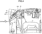
FIG. 4 is a diagram schematically illustrating an example of a lock operation device according to the first embodiment. -
FIG. 5 is a functional block diagram illustrating an example of a periphery monitoring system according to the first embodiment. -
FIG. 6 is a flowchart illustrating an example of a periphery monitoring process according to the first embodiment. -
FIG. 7 is a diagram schematically illustrating an example of a display device according to the first embodiment. -
FIG. 8 is a sequence diagram illustrating an example of the periphery monitoring process according to the first embodiment. -
FIG. 9 is a sequence diagram illustrating an example of a periphery monitoring process according to a second embodiment. -
FIG. 10 is a sequence diagram illustrating an example of a periphery monitoring process according to a third embodiment. -
FIG. 11 is a sequence diagram illustrating an example of a periphery monitoring process according to a fourth embodiment. -
FIG. 12 is a side view illustrating an example of a work vehicle according to a fifth embodiment. -
FIG. 13 is a block diagram illustrating an example of a computer system. - Hereinafter, embodiments according to the invention will be described with reference to the drawings, but the invention is not limited thereto. Components to be described below can be appropriately combined with each other. Further, there is a case where a part of the components are not used.
- A first embodiment will be described.
FIG. 1 is a side view illustrating an example of awork vehicle 1 according to the embodiment. In the embodiment, thework vehicle 1 is awheel loader 1 which is a kind of an articulated work vehicle. Thewheel loader 1 loads an excavated material scooped by abucket 12 onto a transportation vehicle or discharges the excavated material to a predetermined discharge place. - As illustrated in
FIG. 1 , thewheel loader 1 includes avehicle body 2, acab 3, a traveling device 4, and aworking machine 10. - The
vehicle body 2 includes a frontvehicle body part 2F and a rearvehicle body part 2R. The frontvehicle body part 2F and the rearvehicle body part 2R are bendably connected to each other through anarticulation mechanism 9. A steering cylinder (not illustrated) is provided in thearticulation mechanism 9 and the steering cylinder is moved in a telescopic manner so that thevehicle body 2 is bent. - The
cab 3 is supported by thevehicle body 2. Thecab 3 is provided with adriving room 3R. Thewheel loader 1 is driven by a passenger getting on thedriving room 3R. The passenger includes an operator who performs an actual work by driving thewheel loader 1 and a service man who performs a maintenance work of thewheel loader 1. The actual work includes at least one of an excavation work for excavating a material to be excavated by using the workingmachine 10 and a transportation work for carrying and discharging an excavated material. - The traveling device 4 supports the
vehicle body 2. The traveling device 4 includes avehicle wheel 5. Thevehicle wheel 5 is rotated by power generated by an engine mounted on thevehicle body 2. Atire 6 is attached to thevehicle wheel 5. Thevehicle wheel 5 includes twofront wheels 5F which are supported by the frontvehicle body part 2F and tworear wheels 5R which are supported by the rearvehicle body part 2R. Thetire 6 includes afront tire 6F which is attached to thefront wheel 5F and arear tire 6R which is attached to therear wheel 5R. The traveling device 4 can travel on a ground RS. The traveling device 4 includes anarticulation mechanism 9 which bends and turns thevehicle body 2. - The
front wheel 5F and thefront tire 6F are rotatable about a rotation axis FX. Therear wheel 5R and therear tire 6R are rotatable about a rotation axis RX. - In the description below, a direction parallel to the rotation axis FX of the
front tire 6F will be appropriately referred to as the vehicle width direction, a direction orthogonal to a contact surface of thefront tire 6F contacting the ground RS will be appropriately referred to as the vertical direction, and a direction orthogonal to both the vehicle width direction and the vertical direction will be appropriately referred to as the longitudinal direction. In a case where thewheel loader 1 travels straight ahead, the rotation axis FX and the rotation axis RX are parallel to each other. - Further, in the description below, a position or a direction close to the center of the
vehicle body 2 in the vehicle width direction will be appropriately referred to as the inside or the inward direction in the vehicle width direction and a position or a direction far from the center of thevehicle body 2 will be appropriately referred to as the outside or the outward direction in the vehicle width direction. Further, one side based on a driver seat 17 (seeFIG. 3 ) of thedriving room 3R in the vehicle width direction will be appropriately referred to as the right side or the rightward direction and a side or a direction opposite to the right side or the rightward direction will be appropriately referred to as the left side or the leftward direction. Further, a position or a direction close to the workingmachine 10 based on thedriver seat 17 of thedriving room 3R in the longitudinal direction will be appropriately referred to as the front side or the forward direction and a side or a direction opposite to the front side or the forward direction will be appropriately referred to as the rear side or the backward direction. Further, a position or a direction close to a contact surface of thefront tire 6F in the vertical direction will be appropriately referred to as the downside or the downward direction and a side or a direction opposite to the downside or the downward direction will be appropriately referred to as the upside or the upward direction. - An
entrance 7 is provided at the left side of thedriving room 3R. Theentrance 7 is opened or closed by a door. Further, astep 8 is provided at the left side of the rearvehicle body part 2R. Ahandrail 8H is provided along thestep 8. The passenger can enter thedriving room 3R through theentrance 7 after getting on thestep 8. Further, the passenger who exists in thedriving room 3R can get off thestep 8 after leaving from thedriving room 3R through theentrance 7. - The working
machine 10 is supported by thevehicle body 2. At least a part of the workingmachine 10 is disposed at the front side of thefront tire 6F. The workingmachine 10 includes aboom 11 which is movably connected to thevehicle body 2, abucket 12 which is movably connected to theboom 11, abell crank 15, and alink 16. - The
boom 11 is operated by power generated by aboom cylinder 13. One end portion of theboom cylinder 13 is connected to thevehicle body 2. The other end portion of theboom cylinder 13 is connected to theboom 11. When the passenger operates a boom operation lever 18H, theboom cylinder 13 moves in a telescopic manner. When theboom cylinder 13 moves in a telescopic manner, theboom 11 moves upward or downward. - The
bucket 12 is a working member including atip portion 12B with a cutting edge. Thebucket 12 is disposed at the front side of thefront tire 6F. Thebucket 12 is connected to a front end portion of theboom 11. Thebucket 12 is operated by power generated by abucket cylinder 14. A center portion of the bell crank 15 is rotatably connected to theboom 11. One end portion of thebucket cylinder 14 is connected to thevehicle body 2. The other end portion of thebucket cylinder 14 is connected to one end portion of thebell crank 15. The other end portion of the bell crank 15 is connected to thebucket 12 through thelink 16. When the passenger operates a bucket operation lever 181, thebucket cylinder 14 moves in a telescopic manner. When thebucket cylinder 14 moves in a telescopic manner, thebucket 12 performs a dumping operation or a tilting operation. - The
wheel loader 1 includes aperiphery monitoring system 100 which monitors the periphery of thewheel loader 1 and allows the passenger of thewheel loader 1 to recognize the peripheral state of thewheel loader 1. Theperiphery monitoring system 100 includes anobject detection device 20. -
FIG. 2 is a diagram schematically illustrating an example of a range in which theobject detection device 20 according to the embodiment detects an object. Theobject detection device 20 detects an object in the periphery of thewheel loader 1. As illustrated inFIGS. 1 and2 , theobject detection device 20 includes acamera 21 which photographs an object in the periphery of thewheel loader 1 and anon-contact sensor 22 which detects an object in the periphery of thewheel loader 1 in a non-contact manner. - A plurality of the
cameras 21 is mounted on thewheel loader 1 and acquires an image of an object in the periphery of thewheel loader 1. Thecamera 21 is provided on an outer surface of thevehicle body 2 of thewheel loader 1. Thecamera 21 includes acamera 21A which is provided in the frontvehicle body part 2F andcameras vehicle body part 2R. - The
camera 21A photographs an imaging area SA defined at the front side of thevehicle body 2. Thecamera 21B photographs an imaging area SB defined at the right side of thevehicle body 2. Thecamera 21C photographs an imaging area SC defined at the right side and the right rear side of thevehicle body 2. Thecamera 21D photographs an imaging area SD defined at the rear side of thevehicle body 2. Thecamera 21E photographs an imaging area SE defined at the left side and the left rear side of thevehicle body 2. Thecamera 21F photographs an imaging area SF defined at the left side of thevehicle body 2. - A plurality of the
non-contact sensors 22 is mounted on thewheel loader 1 and detects an object in the periphery of thewheel loader 1 in a non-contact manner. Thenon-contact sensor 22 generates object position data as detection data of theobject detection device 20. The object position data includes object existence data and distance data to the object. Thenon-contact sensor 22 includes a radar device capable of detecting an object in a non-contact manner by emitting radio waves to the object. In addition, thenon-contact sensor 22 may include a laser scanner device capable of detecting an object in a non-contact manner by emitting a laser beam to the object. Thenon-contact sensor 22 may include an ultrasonic sensor device capable of detecting an object in a non-contact manner by emitting ultrasonic waves to the object. Thenon-contact sensor 22 is provided on an outer surface of thevehicle body 2 of thewheel loader 1. Thenon-contact sensor 22 includesnon-contact sensors vehicle body part 2R. - The
non-contact sensor 22A detects an object in a detection area DA defined at the right side of thevehicle body 2. Thenon-contact sensor 22B detects an object in a detection area DB defined at the rear side and the left rear side of thevehicle body 2. Thenon-contact sensor 22C detects an object in a detection area DC defined at the rear side and the right rear side of thevehicle body 2. Thenon-contact sensor 22D detects an object in a detection area DD defined at the left side of thevehicle body 2. - The
object detection device 20 can detect objects existing in different areas in the periphery of thewheel loader 1 by using the plurality ofcameras 21 and the plurality ofnon-contact sensors 22. Additionally, in the embodiment, theobject detection device 20 includes both the plurality ofcameras 21 and the plurality ofnon-contact sensors 22, but may include only one of the plurality ofcameras 21 and the plurality ofnon-contact sensors 22. Further, theobject detection device 20 may be, for example, onecamera 21 or onenon-contact sensor 22 provided at the rear end portion of the rearvehicle body part 2R. When theobject detection device 20 includes only one or the plurality ofcameras 21, image data of the object photographed by thecamera 21 is processed by an image processing device. The image processing device processes the image data of the object photographed by thecamera 21 and outputs object position data as detection data of theobject detection device 20. The object position data includes object existence data and distance data to the object. In this case, theobject detection device 20 includes thecamera 21 and the image processing device. -
FIG. 3 is a diagram schematically illustrating an example of thedriving room 3R according to the embodiment.FIG. 3 schematically illustrates a part of thedriving room 3R when the front side is viewed from the rear part of thedriving room 3R. As illustrated inFIG. 3 , thedriving room 3R is provided with thedriver seat 17 on which the passenger sits and a drivingoperation device 18 which is operated by the passenger. The drivingoperation device 18 includes anaccelerator pedal 18A, aright brake pedal 18B, aleft brake pedal 18C, asteering lever 18D, a forward/reverse changeover switch 18E, a shift-down switch 18F, a shift-upswitch 18G, a boom operation lever 18H, and a bucket operation lever 181. The passenger can drive, brake, and swing the traveling device 4, change the forward/reverse traveling state, adjust the traveling speed, and operate the workingmachine 10 by operating the drivingoperation device 18. - The
accelerator pedal 18A is operated to drive the traveling device 4. Theright brake pedal 18B and theleft brake pedal 18C are operated to brake the traveling device 4. Theaccelerator pedal 18A, theright brake pedal 18B, and theleft brake pedal 18C are disposed at a position located at the front side of thedriver seat 17 and the lower side of thedriver seat 17 and are operated by a foot of the passenger sitting on thedriver seat 17. - The
steering lever 18D is operated to swing thewheel loader 1. When thesteering lever 18D is operated, the steering cylinder of thearticulation mechanism 9 is operated to bend the frontvehicle body part 2F with respect to the rearvehicle body part 2R. Thesteering lever 18D is disposed at a position located at the left side of thedriver seat 17 and the front side of thedriver seat 17 and is operated by a left hand of the passenger sitting on thedriver seat 17. - The forward/
reverse changeover switch 18E is operated to switch the forward and reverse traveling state of the traveling device 4. The shift-down switch 18F and the shift-upswitch 18G are operated to switch a gear ratio of a transmission of the traveling device 4. The forward/reverse changeover switch 18E, the shift-down switch 18F, and the shift-upswitch 18G are disposed at thesteering lever 18D and are operated by a left hand of the passenger sitting on thedriver seat 17. - The boom operation lever 18H is operated to operate the
boom 11 of the workingmachine 10. The bucket operation lever 181 is operated to operate thebucket 12 of the workingmachine 10. The boom operation lever 18H and the bucket operation lever 181 are disposed at a position located at the right side of thedriver seat 17 and the front side of thedriver seat 17 and are operated by a right hand of the passenger sitting on thedriver seat 17. - Further, the
driving room 3R is provided with astart switch 25 and aparking brake switch 26. - The
start switch 25 is operated to start an engine of thewheel loader 1. When thestart switch 25 is operated after a key is inserted into a keyhole provided in thedriving room 3R to become a key-on state so that apower source 70 of thewheel loader 1 is activated, the engine of thewheel loader 1 is started. - The
parking brake switch 26 is operated to operate the parking brake of thewheel loader 1. - Further, the
driving room 3R is provided with amonitor device 27 and a rearview monitoring device 28. Themonitor device 27 is disposed at the front side of thedriver seat 17. The rearview monitoring device 28 is disposed at a position located at the right side of thedriver seat 17 and the front side of thedriver seat 17. - Further, the
driving room 3R is provided with amonitoring monitor device 30. Themonitoring monitor device 30 is disposed at a position located at the right side of thedriver seat 17 and the front side of thedriver seat 17. Themonitoring monitor device 30 includes awarning device 31 which outputs a warning sound and adisplay device 32 which displays display data. - The
warning device 31 outputs a warning sound based on the detection data of theobject detection device 20. In a case where an obstacle existing in the periphery of thewheel loader 1 is detected by theobject detection device 20, thewarning device 31 outputs a warning sound. Thewarning device 31 includes a buzzer device capable of outputting a warning sound. In addition, thewarning device 31 may include a light emitting device such as a lamp instead of the buzzer device. Alternatively, thewarning device 31 may include both the buzzer device and the light emitting device. - The
display device 32 displays display data generated based on the detection data of theobject detection device 20. Thedisplay device 32 displays image data in the periphery of thewheel loader 1 acquired by thecamera 21. When an obstacle exists in the periphery of thewheel loader 1, thedisplay device 32 displays obstacle position data detected by thenon-contact sensor 22. Thedisplay device 32 includes a flat panel display such as a liquid crystal display (LCD) or an organic electroluminescence display (OELD). - Further, the
driving room 3R is provided with a canceloperation device 33 which stops an output of the warning sound from thewarning device 31. The canceloperation device 33 is provided at the right side of thedriver seat 17. When the canceloperation device 33 is operated, the output of the warning sound is stopped. There is a case where the passenger needs to stop the output of the warning sound from thewarning device 31. The passenger can stop the output of the warning sound by operating the canceloperation device 33. - The cancel
operation device 33 includes, for example, a rocker switch or a push button. In the description below, the canceloperation device 33 will be appropriately referred to as a cancelswitch 33. - In addition, the
display device 32 may include a touch panel and the touch panel may have a function of the canceloperation device 33. - Further, the
driving room 3R is provided with alock operation device 40 which is operated by the passenger to limit the driving of the driving mechanism of thewheel loader 1. The driving mechanism of thewheel loader 1 includes the workingmachine 10 and the traveling device 4. Thelock operation device 40 includes a working machine locking switch 41 which is operated by the passenger to limit the driving of the workingmachine 10 and asteering locking lever 42 which is operated by the passenger to limit the driving of the traveling device 4. In the embodiment, a case of limiting the driving of the traveling device 4 includes a case of locking the traveling device 4 so that the traveling device cannot be operated. A case of locking the traveling device 4 so that the traveling device cannot be operated includes a case of prohibiting the forward and backward traveling operation of thewheel loader 1 and a case of prohibiting the swinging operation of thewheel loader 1 in which the steering cylinder of thearticulation mechanism 9 is operated and the frontvehicle body part 2F is bent with respect to the rearvehicle body part 2R. In addition, a case of limiting the driving of the traveling device 4 may include a case of prohibiting any one of the forward and backward traveling operation and the swinging operation. - The working machine locking switch 41 includes, for example, a rocker switch and is disposed at a position located at the front side of the
driver seat 17 and the right side of thedriver seat 17. In addition, an operation lever may be provided as the working machine locking switch 41. The working machine locking switch 41 is provided in the vicinity of the boom operation lever 18H and the bucket operation lever 181 for operating the workingmachine 10. The working machine locking switch 41 can be switched between a lock position and a free position. When the working machine locking switch 41 is operated to be disposed at the lock position, a lock state is set in which the operation of the boom operation lever 18H and the bucket operation lever 181 is locked and the driving of the workingmachine 10 is limited. In the lock state, the workingmachine 10 cannot be operated. When the working machine locking switch 41 is operated to be disposed at the free position, a free state is set in which the locking of the operation of the boom operation lever 18H and the bucket operation lever 181 is released and the limiting of the driving of the workingmachine 10 is released. In the free state, the workingmachine 10 can be operated. - The
steering locking lever 42 is disposed at a position located at the front side of thedriver seat 17 and the left side of thedriver seat 17. Thesteering locking lever 42 is disposed in the vicinity of thesteering lever 18D for operating the traveling device 4. Thesteering locking lever 42 can be switched between a lock position L2 and a free position F2. When thesteering locking lever 42 is operated to be disposed at the lock position L2, a lock state is set in which thesteering lever 18D is locked and the driving of the traveling device 4 is limited. In the lock state, thewheel loader 1 cannot travel and swing. When thesteering locking lever 42 is operated to be disposed at the free position F2, a free state is set in which the locking of thesteering lever 18D is released and the limiting of the driving of the traveling device 4 is released. In the free state, thewheel loader 1 can travel and swing. -
FIG. 4 is a diagram schematically illustrating an example of thesteering locking lever 42 according to the embodiment. As illustrated inFIGS. 3 and4 , thesteering locking lever 42 is provided in a boarding passage RT of thedriving room 3R through which the passenger passes in a case where the passenger gets on thedriving room 3R. - The boarding passage RT of the
driving room 3R is a path which connects theentrance 7 and thedriver seat 17 in thedriving room 3R. The passenger is movable through the boarding passage RT. In a case where the passenger existing outside thedriving room 3R gets on thedriving room 3R, the passenger enters thedriving room 3R through theentrance 7 provided at the left side of thecab 3. The passenger who enters thedriving room 3R moves to thedriver seat 17 through the boarding passage RT of thedriving room 3R and sits on thedriver seat 17. In a case where the passenger sitting on thedriver seat 17 leaves from thedriving room 3R, the passenger stands up from thedriver seat 17, moves to theentrance 7 through the boarding passage RT of thedriving room 3R, and leaves to the outside of thedriving room 3R. - The
steering locking lever 42 is provided in the boarding passage RT of thedriving room 3R connecting theentrance 7 and thedriver seat 17. Thesteering locking lever 42 is rotatably supported on a floor surface of thedriving room 3R. - The
steering locking lever 42 is a bar-shaped member. Thesteering locking lever 42 includes asupport pillar portion 42A which is supported on the floor surface, anarm portion 42B which is connected to an upper end portion of thesupport pillar portion 42A, and ahandle portion 42C which is connected to a front end portion of thearm portion 42B. Thesupport pillar portion 42A is formed upright on the floor surface to extend in the vertical direction. Thesupport pillar portion 42A is rotatably supported on the floor surface of thedriving room 3R. The rotation axis of thesupport pillar portion 42A is substantially orthogonal to the floor surface of thedriving room 3R. A base end portion of thearm portion 42B is connected to the upper end portion of thesupport pillar portion 42A. Thearm portion 42B extends radially outward of the rotation axis of the support pillar portion 41A. Thearm portion 42B is formed upright from a portion connected to thesupport pillar portion 42A toward a portion connected to thehandle portion 42C. That is, thearm portion 42B extends obliquely upward. Thehandle portion 42C extends upward from the front end portion of thearm portion 42B. The passenger holds thehandle portion 42C and operates thesteering locking lever 42 to rotate thesteering locking lever 42 about the rotation axis of thesupport portion 42A. - As illustrated in
FIG. 4 , thesteering locking lever 42 is rotatable to move between the lock position L2 and the free position F2. InFIG. 4 , thesteering locking lever 42 located at the lock position L2 is indicated by a solid line and thesteering locking lever 42 located at the free position F2 is indicated by a dashed line. When thesteering locking lever 42 is disposed at the lock position L2, thearm portion 42B is retracted from the boarding passage RT and the boarding passage RT is opened. When thesteering locking lever 42 is disposed at the free position F2, thearm portion 42B is disposed in the boarding passage RT to block the passage of the passenger and the boarding passage RT is closed. - That is, when the
steering locking lever 42 is disposed at the lock position L2, the boarding passage RT is opened so that a passage allowing state is set in which the passenger can pass through the boarding passage RT. When thesteering locking lever 42 is disposed at the free position F2, the boarding passage RT is closed so that a passage prohibiting state is set in which the passenger cannot pass through the boarding passage RT or cannot easily pass through the boarding passage. - In this way, the
steering locking lever 42 is operated by the passenger so that the boarding passage RT changes from one state of the passage allowing state and the passage prohibiting state to the other state thereof. - In a case where the passenger sits on the
driver seat 17 and operates thewheel loader 1, the passenger disposes the working machine locking switch 41 at the free position and disposes thesteering locking lever 42 at the free position F2. Accordingly, a free state is set in which the driving mechanism of thewheel loader 1 including the traveling device 4 and the workingmachine 10 can be operated. The passenger can perform an actual work or a maintenance work by operating the drivingoperation device 18. - In a case where the passenger leaves from the
driving room 3R, the passenger causes thebucket 12 of the workingmachine 10 to contact a ground and operates theparking brake switch 26 to operate the parking brake. Further, the passenger disposes the working machine locking switch 41 at the lock position and disposes thesteering locking lever 42 at the lock position L2. When the working machine locking switch 41 is disposed at the lock position, a lock state is set in which the workingmachine 10 cannot be operated. When thesteering locking lever 42 is disposed at the lock position L2, a lock state is set in which the traveling device 4 cannot be operated. Accordingly, in a case where the passenger does not exist in thedriving room 3R, it is possible to suppress the movement of the workingmachine 10 and the traveling device 4. Further, when thesteering locking lever 42 is disposed at the lock position L2, the passenger sitting on thedriver seat 17 can smoothly leave to the outside of thedriving room 3R through the boarding passage RT. - In a case where the passenger gets on the
driving room 3R, the passenger moves from theentrance 7 to thedriver seat 17 through the boarding passage RT. Since thesteering locking lever 42 is disposed at the lock position L2, the passenger cannot smoothly move to thedriver seat 17 through the boarding passage RT. After the passenger sits on thedriver seat 17, the passenger disposes the working machine locking switch 41 at the free position and disposes thesteering locking lever 42 at the free position F2. Further, the passenger turns off theparking brake switch 26 to cancel the operation of the parking brake. Accordingly, the driving mechanism including the traveling device 4 and the workingmachine 10 can move in a free state. Further, the passenger operates thepower source 70 and thestart switch 25 in a key-on state. Accordingly, the engine of thewheel loader 1 is activated. The passenger can perform an actual work or a maintenance work by operating the drivingoperation device 18. - The
wheel loader 1 includes a boardingstate detection device 43 which detects a passenger boarding state in thedriving room 3R. The passenger boarding state in thedriving room 3R includes a state where the passenger exists or does not exist in thedriving room 3R. Further, the passenger boarding state in thedriving room 3R includes a state where the passenger sits or does not sit on thedriver seat 17. - The passenger boarding state in the
driving room 3R includes the operation state of thesteering locking lever 42. The boardingstate detection device 43 detects the operation state of thesteering locking lever 42. In the embodiment, the boardingstate detection device 43 includes a pressure sensor which is disposed in a hydraulic circuit provided with a valve operated by thesteering locking lever 42. - The valve is connected to the lower end portion of the
support portion 42A of thesteering locking lever 42. The valve is provided in the hydraulic circuit. The hydraulic circuit circulates hydraulic oil for driving the traveling device 4. The valve can open and close the hydraulic circuit. The pressure sensor is disposed at the downstream side of the valve in the hydraulic circuit. When thesteering locking lever 42 is switched between the lock position L2 and the free position F2, the valve is operated so that the hydraulic circuit is opened or closed. When the hydraulic circuit is opened or closed by the valve, a pressure at the downstream side of the valve changes. The pressure sensor which is provided at the downstream side of the valve can detect a state where the hydraulic circuit is opened so that the hydraulic oil flows and a state where the hydraulic circuit is closed so that the hydraulic oil does not flow. Based on the detection data of the pressure sensor, the operation state of thesteering locking lever 42 is detected. In the description below, the boardingstate detection device 43 will be appropriately referred to as thelever sensor 43. - In addition, a detection device capable of directly detecting the position of the
steering locking lever 42 such as a contact switch or an encoder may be used as the boardingstate detection device 43 which detects the operation state of thesteering locking lever 42. - The operation state of the
steering locking lever 42 includes the passage prohibiting state where thesteering locking lever 42 is disposed at the free position F2 and the passage allowing state where the steering locking lever is disposed at the lock position L2. Thelever sensor 43 detects a state where thesteering locking lever 42 is disposed at anyone of the free position F2 and the lock position L2. As described above, thesteering locking lever 42 is disposed at the free position F2 in a case where the passenger existing in thedriving room 3R drives thewheel loader 1. Thesteering locking lever 42 is disposed at the lock position L2 in a case where the passenger leaves from thedriving room 3R. For that reason, the passage prohibiting state where thesteering locking lever 42 is disposed at the free position F2 can be considered as a state where the passenger exists in thedriving room 3R. The passage allowing state where thesteering locking lever 42 is disposed at the lock position L2 can be considered as a state where the passenger does not exist in thedriving room 3R. Thus, thelever sensor 43 can detect whether the passenger exists in thedriving room 3R by detecting whether thesteering locking lever 42 is disposed at the free position F2. - In the description below, the detection data output from the
lever sensor 43 in the passage prohibiting state where thesteering locking lever 42 is disposed at the free position F2 will be appropriately referred to as the boarding detection data and the detection data output from thelever sensor 43 in the passage allowing state where thesteering locking lever 42 is disposed at the lock position L2 will be appropriately referred to as the non-boarding detection data. In the embodiment, the detection data of the boardingstate detection device 43 detecting the passenger boarding state in thedriving room 3R is the detection data output from thelever sensor 43. -
FIG. 5 is a functional block diagram illustrating an example of theperiphery monitoring system 100 according to the embodiment. As illustrated inFIG. 5 , avehicle control device 50 and amonitoring control device 60 are mounted on thewheel loader 1. Thevehicle control device 50 controls the movable mechanism of thewheel loader 1 including the traveling device 4 and the workingmachine 10. Theperiphery monitoring system 100 includes themonitoring control device 60. Themonitoring control device 60 controls theperiphery monitoring system 100. - The
vehicle control device 50 is connected to each of thelever sensor 43 and the drivingoperation device 18. Themonitoring control device 60 is connected to each of thevehicle control device 50, theobject detection device 20, themonitoring monitor device 30, and the cancelswitch 33. - An electronic device of the
wheel loader 1 including thevehicle control device 50, themonitoring control device 60, thelever sensor 43, the drivingoperation device 18, the cancelswitch 33, theobject detection device 20, and themonitoring monitor device 30 is operated based on the power supplied from thepower source 70 mounted on thewheel loader 1. When the passenger sets the key-on state, thepower source 70 is operated. When the passenger sets the key-off state, the operation of thepower source 70 is stopped. In the key-on state, the electronic device of thewheel loader 1 is operated by the power supplied from thepower source 70. In the key-off state, the operation of the electronic device of thewheel loader 1 is stopped. - The
vehicle control device 50 includes a boardingstate communication unit 51 and anoperation control unit 52. - The boarding
state communication unit 51 receives the detection data of thelever sensor 43 representing the passenger boarding state in thedriving room 3R from thelever sensor 43 and transmits the detection data to themonitoring control device 60. Further, the boardingstate communication unit 51 outputs the detection data of thelever sensor 43 to theoperation control unit 52. - The
operation control unit 52 receives an operation signal from the drivingoperation device 18. In a case where the drivingoperation device 18 is operated by the passenger, based on an operation amount of the drivingoperation device 18, an operation signal is output from the drivingoperation device 18. Theoperation control unit 52 outputs an instruction signal for controlling the traveling device 4 and the workingmachine 10 based on the operation signal from the drivingoperation device 18. In a case where thelever sensor 43 detects a state where thesteering locking lever 42 is disposed at the lock position L2, theoperation control unit 52 outputs an instruction signal for limiting the driving of the traveling device 4 based on the non-boarding detection data of thelever sensor 43. - The
monitoring control device 60 includes a boardingstate receiving unit 61, an invalidatinginstruction receiving unit 62, anobstacle detection unit 63, an operationinstruction output unit 64, an invalidatingunit 65, a validatingunit 66, adetermination unit 67, awarning control unit 68, and adisplay control unit 69. - The boarding
state receiving unit 61 receives the detection data of thelever sensor 43 from the boardingstate communication unit 51. - The invalidating
instruction receiving unit 62 receives an invalidating instruction output from the cancelswitch 33. When the cancelswitch 33 is operated, an invalidating instruction for stopping the output of the warning sound is output from the cancelswitch 33. The invalidatinginstruction receiving unit 62 receives the invalidating instruction output from the cancelswitch 33. - The
obstacle detection unit 63 receives the detection data of theobject detection device 20. In a case where an obstacle exists in the periphery of thewheel loader 1 and theobject detection device 20 detects the obstacle, theobject detection device 20 outputs detection data representing a state where the obstacle exists. Theobstacle detection unit 63 receives the detection data representing a state where the obstacle exists in the periphery of thewheel loader 1 from theobject detection device 20. - The operation
instruction output unit 64 receives the detection data of theobject detection device 20 from theobstacle detection unit 63. The operationinstruction output unit 64 outputs an operation instruction to thewarning device 31 based on the detection data of theobject detection device 20. In a case where the detection data representing a state where the obstacle exists in the periphery of thewheel loader 1 is received, the operationinstruction output unit 64 outputs an operation instruction to thewarning device 31 to output a warning sound. When the warning sound is output, the passenger can recognize a state where the obstacle exists in the periphery of thewheel loader 1. - The invalidating
unit 65 receives an invalidating instruction from the invalidatinginstruction receiving unit 62. The invalidatingunit 65 invalidates the operation instruction of the operationinstruction output unit 64 based on the invalidating instruction output from the cancelswitch 33. - A case of invalidating the operation instruction includes at least one of a case where the operation instruction becomes invalid, a case where the output of the operation instruction to the
warning device 31 is stopped, and a case where the invalidating instruction is output to thewarning device 31 so that the warning sound cannot be output. When the operation instruction becomes invalid, thewarning device 31 cannot output the warning sound. Thewarning device 31 stops the output of the warning sound. When the operation instruction becomes invalid, thewarning device 31 does not output the warning sound even when theobject detection device 20 detects the obstacle. - The validating
unit 66 receives the detection data of thelever sensor 43 from the boardingstate receiving unit 61. The validatingunit 66 validates the invalidated operation instruction based on the detection data of thelever sensor 43. In a case where thesteering locking lever 42 is operated in a specific operation state, the validatingunit 66 validates the invalidated operation instruction based on the detection data of thelever sensor 43. - A case of validating the operation instruction includes at least one of a case of validating the invalidated operation instruction, a case of canceling the stop of the output of the operation instruction to the
warning device 31, and a case of outputting a valid instruction to thewarning device 31 so that a warning can be output therefrom. When the operation instruction is validated, thewarning device 31 can output the warning sound. In a case where theobject detection device 20 detects an obstacle, thewarning device 31 outputs a warning sound. - The
determination unit 67 determines whether the passenger gets on thedriving room 3R based on the detection data of thelever sensor 43. The validatingunit 66 validates the invalidated operation instruction based on the determination of thedetermination unit 67. - The
warning control unit 68 outputs an instruction signal for controlling thewarning device 31. In a case where the operation instruction of the operationinstruction output unit 64 is valid, thewarning control unit 68 outputs a valid instruction to thewarning device 31. When the valid instruction is received, thewarning device 31 can output a warning sound. In a case where theobject detection device 20 detects an obstacle, thewarning device 31 outputs the warning sound. In a case where the operation instruction of the operationinstruction output unit 64 is invalid, thewarning control unit 68 outputs an invalidating instruction to thewarning device 31. When the invalidating instruction is received, thewarning device 31 cannot output the warning sound. Even when theobject detection device 20 detects the obstacle, thewarning control unit 68 does not output the warning sound from thewarning device 31. - The
display control unit 69 outputs an instruction signal for controlling thedisplay device 32. - In a case where the operation instruction of the operation
instruction output unit 64 is valid, thedisplay control unit 69 displays display data representing a state where the operation instruction is valid on thedisplay device 32. In a case where the operation instruction of the operationinstruction output unit 64 is invalid, thedisplay control unit 69 displays display data representing a state where the operation instruction is invalid on thedisplay device 32. -
FIG. 6 is a flowchart illustrating an example of the periphery monitoring process according to the periphery monitoring method of the embodiment. When the passenger sets the key-on state so that thepower source 70 is activated, the periphery monitoring process is started. In the key-on state, the operation instruction output from the operationinstruction output unit 64 is valid and thewarning device 31 can output the warning sound. - After the key-on state is set, the invalidating
unit 65 determines whether the invalidating instruction is output from the cancel switch 33 (step S1). - In step S1, when it is determined that the invalidating instruction is not output (step S1: No), the operation instruction output from the operation
instruction output unit 64 is kept in a valid state (step S2). That is, a state where thewarning device 31 can output a warning is kept. - The
obstacle detection unit 63 determines whether an obstacle exists in the periphery of thewheel loader 1 based on the detection data of the object detection device 20 (step S3). - In step S3, when it is determined that the obstacle does not exist (step S3: No), the state of the operation
instruction output unit 64 is kept. - In step S3, when it is determined that the obstacle exists (step S3: Yes), the operation
instruction output unit 64 outputs an operation instruction to thewarning device 31 through the warning control unit 68 (step S4). Thewarning control unit 68 transmits a valid instruction to thewarning device 31 based on the operation instruction output from the operationinstruction output unit 64 and outputs a warning sound. - In step S1, when it is determined that a invalidating instruction is output (step S1: Yes), the invalidating
unit 65 invalidates the operation instruction output from the operation instruction output unit 64 (step S5). Accordingly, thewarning device 31 changes from a state where the warning can be output to a state where the warning cannot be output. - The
determination unit 67 determines whether the passenger boarding state in thedriving room 3R is a specific boarding state based on the detection data of the lever sensor 43 (step S6). - In step S6, when it is determined that a current boarding state is the specific boarding state (step S6: Yes), the validating
unit 66 validates the invalidated operation instruction (step S7). Accordingly, the operation instruction output from the operationinstruction output unit 64 is validated and thewarning device 31 changes from a state where the warning cannot be output to a state where the warning can be output. - In step S6, when it is determined that the current boarding state is not the specific boarding state (step S6: No), the operation instruction output from the operation
instruction output unit 64 is invalidated (step S8). That is, a state where thewarning device 31 cannot output the warning is kept. - The
display control unit 69 displays display data representing a state where the operation instruction is valid or invalid on the display device 32 (step S9). - The
determination unit 67 determines whether the key-off state is set (step S10). Themonitoring control device 60 performs processes from step S1 to step S10 at a predetermined cycle. In step S10, when it is determined that the key-off state is not set (step S10: No), a routine returns to step S1. In step S10, when it is determined that the key-off state is set (step S10: Yes), the periphery monitoring process ends. -
FIG. 7 is a diagram schematically illustrating an example of thedisplay device 32 according to the embodiment. As illustrated inFIG. 7 , thedisplay control unit 69 displays a character image CG and an bird's eye image BI of thewheel loader 1 on afirst area 32A of a display screen of thedisplay device 32 and displays an image representing the rear side of thewheel loader 1 photographed by thecamera 21D on asecond area 32B of the display screen in the vicinity of thefirst area 32A. In addition,FIG. 7 illustrates a display example of thedisplay device 32 when thewheel loader 1 travels backward. - The
display control unit 69 displays lines LG indicating boundaries of imaging areas SBp, SCp, SDp, SEp, and SFp of the plurality ofcameras - Further, the
display control unit 69 displays lines La, Lb, and Lc indicating a distance from the outer edge of thewheel loader 1 on the bird's eye image BI in a superimposed state. The outer edge of thewheel loader 1 is a line forming the outer shape of thewheel loader 1 in the plan view in which thewheel loader 1 is viewed from above in a posture in which thewheel loader 1 can travel straight ahead. - Further, the
display control unit 69 displays amark 34 indicating the position of the obstacle detected by thenon-contact sensor 22 on the bird's eye image BI in a superimposed state. For example, in a case where an obstacle existing at the rear side of thewheel loader 1 is detected by thenon-contact sensor 22, thedisplay control unit 69 displays themark 34 on the obstacle displayed on the bird's eye image BI based on the obstacle position data. Accordingly, since the existing obstacle is highlighted, the passenger of thewheel loader 1 can promptly recognize the existence and the position of the obstacle. - An
indicator 35 indicating an imaging area of thecamera 21 displayed on thesecond area 32B in the imaging areas of the plurality ofcameras 21 is displayed on thesecond area 32B. - Further, an
icon 36 which is display data indicating a state where the operation instruction of the operationinstruction output unit 64 is valid is displayed on thesecond area 32B. In a case where the operation instruction is valid, theicon 36 is displayed. In a case where the operation instruction is invalid, theicon 36 is not displayed. Based on whether theicon 36 is displayed, the passenger can recognize a state where thewarning device 31 can output the warning sound. In addition, in a case where the operation instruction is not valid, display data representing a state where the operation instruction is invalid may be displayed. An icon of a first pattern may be displayed in a case where the operation instruction is valid and an icon of a second pattern different from the first pattern may be displayed in a case where the operation instruction is invalid. - In a case where the
wheel loader 1 travels backward, thedisplay control unit 69 displays lines Lf, Lg, and Lh indicating a distance from the rear end portion of thewheel loader 1 on a photographed image in a superimposed state. The rear end portion of thewheel loader 1 can be set as, for example, a rear end of a rear bumper provided at the rearmost portion of the rearvehicle body part 2R. -
FIG. 8 is a sequence diagram illustrating an example of the periphery monitoring process according to the periphery monitoring method of the embodiment. The operator getting on thedriving room 3R moves thesteering locking lever 42 from the lock position L2 to the free position F2 and moves the working machine locking switch 41 from the lock position to the free position. When the operator sets the key-on state, thepower source 70 is activated. Thelever sensor 43 transmits boarding detection data representing a state where the operator gets on thedriving room 3R to the monitoring control device 60 (step S301). - The
determination unit 67 determines that the operator gets on thedriving room 3R based on the boarding detection data of thelever sensor 43. - The operator performs an actual work by operating the driving
operation device 18. In a case where theobject detection device 20 detects an obstacle, theobject detection device 20 transmits detection data representing a state where the obstacle exists in the periphery of thewheel loader 1 to the monitoring control device 60 (step S101) . - In a state where the cancel
switch 33 is not operated after the key-on state is set, the operation instruction output from the operationinstruction output unit 64 is valid and thewarning device 31 can output a warning. The operationinstruction output unit 64 outputs an operation instruction for outputting a warning to thewarning device 31. Thewarning control unit 68 transmits the operation instruction to the warning device 31 (step S401) . - The
warning device 31 outputs a warning based on the operation instruction transmitted from the warning control unit 68 (step S501). Accordingly, the operator can recognize a state where the obstacle exists in the periphery of thewheel loader 1. - For example, in a case where the
wheel loader 1 enters a building or performs a work inside the building, if theobject detection device 20 detects a wall surface of the building as an obstacle when an obstacle does not exist in the periphery of thewheel loader 1 or the passenger clearly recognizes a state in the periphery of thewheel loader 1, thewarning device 31 outputs an unnecessary warning sound. The unnecessary warning sound is harsh to the operator. There is a case where the operator needs to stop the output of the unnecessary warning sound from thewarning device 31. The operator operates the cancelswitch 33. An invalidating instruction output from the cancelswitch 33 is transmitted to the monitoring control device 60 (step S201). - The invalidating
unit 65 invalidates the operation instruction output from the operationinstruction output unit 64 based on the invalidating instruction output from the cancelswitch 33. Thewarning control unit 68 transmits an invalidating instruction representing a state where the operation instruction is invalidated to the warning device 31 (step S402). - The
warning device 31 changes from a state where the warning sound can be output to a state where the warning sound cannot be output based on the invalidating instruction transmitted from thewarning control unit 68. Thewarning device 31 stops the output of the warning sound (step S502). - For example, for a break or shift work with another operator, the operator getting on the
driving room 3R leaves from thedriving room 3R. In a case where the operator leaves from thedriving room 3R, the operator causes thebucket 12 of the workingmachine 10 to contact a ground and operates theparking brake switch 26 to operate the parking brake. Further, the operator operates the working machine locking switch 41 from the free position to the lock position and moves thesteering locking lever 42 from the free position F2 to the lock position L2. After the operator moves thesteering locking lever 42 to the lock position L2, the operator leaves from thedriving room 3R through the boarding passage RT. Thelever sensor 43 transmits non-boarding detection data representing a state where thesteering locking lever 42 is disposed at the lock position L2 to the monitoring control device 60 (step S302). - The
determination unit 67 determines that the operator does not get on thedriving room 3R based on the non-boarding detection data transmitted from thelever sensor 43. - A next operator gets on the
driving room 3R. The operator getting on thedriving room 3R moves thesteering locking lever 42 from the lock position L2 to the free position F2 and moves the working machine locking switch 41 from the lock position to the free position. Thelever sensor 43 transmits boarding detection data representing a state where thesteering locking lever 42 is disposed at the free position F2 to the monitoring control device 60 (step S303). - The
determination unit 67 determines that the operator gets on thedriving room 3R based on the boarding detection data transmitted from thelever sensor 43. - The validating
unit 66 validates the invalidated operation instruction based on the boarding detection data transmitted from thelever sensor 43. Thewarning control unit 68 transmits a valid instruction representing a state where the operation instruction is validated to the warning device 31 (step S403). - The
warning device 31 changes from a state where the warning sound cannot be output to a state where the warning sound can be output based on the valid instruction transmitted from thewarning control unit 68. When theobject detection device 20 detects an obstacle in a case where thewarning device 31 changes from a state where the warning sound cannot be output to a state where the warning sound can be output, thewarning device 31 outputs the warning sound (step S503). - In this way, in the embodiment, the specific boarding state includes a state where a second passenger gets on the
driving room 3R after a first passenger leaves from thedriving room 3R. The validatingunit 66 validates the invalidated operation instruction in a case where thedetermination unit 67 determines that the second passenger gets on thedriving room 3R after the first passenger leaves from thedriving room 3R. That is, the validatingunit 66 validates the invalidated operation instruction when thesteering locking lever 42 in the passage prohibiting state is operated to the passage allowing state (step S302) and is again operated to the passage prohibiting state (step S303). - In addition, the service man may get on the
driving room 3R after the operator leaves from thedriving room 3R. That is, the passenger is not limited to the operator. - As described above, according to the embodiment, the operation instruction output from the operation
instruction output unit 64 is invalidated based on the invalidating instruction output from the cancelswitch 33 provided in thedriving room 3R. Accordingly, in a case where an unnecessary warning sound is output from thewarning device 31, the passenger can stop the output of the unnecessary warning sound by operating the cancelswitch 33. - Further, the validating
unit 66 validates the invalidated operation instruction when it is determined that the specific boarding state is set based on the detection data of thelever sensor 43 detecting the passenger boarding state in thedriving room 3R. Accordingly, thewarning device 31 can output a necessary warning sound. - In a state where the operator first driving the
wheel loader 1 operates the cancelswitch 33 to stop the output of the warning sound, when the next operator or the service man gets on thewheel loader 1 without recognizing a state where the cancelswitch 33 is operated, there is a possibility that a necessary warning sound may not be output even when thewheel loader 1 approaches the obstacle when the next operator or the service man drives thewheel loader 1. - According to the embodiment, in the specific boarding state where the first passenger leaves from the
driving room 3R and then the second passenger gets on thedriving room 3R, thewarning device 31 changes from a state where the warning sound cannot be output to a state where the warning sound can be output. Thus, even when the second passenger gets on thedriving room 3R without recognizing a state where the cancelswitch 33 is operated by the first passenger, a necessary warning sound is output when thewheel loader 1 approaches the obstacle in a case where the second passenger drives thewheel loader 1. - In this way, according to the embodiment, the output of the unnecessary warning sound is suppressed and the necessary warning sound is output.
- Further, according to the embodiment, the invalidated operation instruction is validated based on the operation state of the
steering locking lever 42 provided in the boarding passage RT of thedriving room 3R. In a case where the first passenger leaves from thedriving room 3R and the second passenger gets on thedriving room 3R, thesteering locking lever 42 is inevitably operated. For that reason, the invalidated operation instruction is reliably validated based on the detection data of thelever sensor 43 detecting the operation state of thesteering locking lever 42. - Further, according to the embodiment, the
icon 36 which is the display data representing a state where the operation instruction is valid or invalid is displayed on thedisplay device 32 provided in thedriving room 3R. Accordingly, the passenger can recognize whether thewarning device 31 can output a warning while seeing thedisplay device 32. -
FIG. 9 is a sequence diagram illustrating an example of a periphery monitoring process according to a periphery monitoring method of the embodiment. Since steps S111, S211, S311, S411, S412, S511, and S512 illustrated inFIG. 9 have the same processes and procedures as those of steps S101, S201, S301, S401, S402, S501, and S502 described with reference toFIG. 8 , a description thereof will be omitted. - The cancel
switch 33 is operated by the operator to stop the output of the warning sound from thewarning device 31 and the operator getting on thedriving room 3R leaves from thedriving room 3R for the replacement with another operator. The operator who is going to leave from thedriving room 3R moves the working machine locking switch 41 from the free position to the lock position and moves thesteering locking lever 42 from the free position F2 to the lock position L2. Thelever sensor 43 transmits the non-boarding detection data to the monitoring control device 60 (step S312). - The validating
unit 66 validates the invalidated operation instruction based on the non-boarding detection data transmitted from thelever sensor 43. Thewarning control unit 68 transmits a valid instruction representing a state where the operation instruction is validated to the warning device 31 (step S413). Thewarning device 31 outputs a warning sound (step S513). - The next operator who gets on the
driving room 3R moves thesteering locking lever 42 from the lock position L2 to the free position F2 and moves the working machine locking switch 41 from the lock position to the free position. Thelever sensor 43 transmits the boarding detection data to the monitoring control device 60 (step S313). - In this way, in the embodiment, the specific boarding state includes a state where the first passenger leaves from the
driving room 3R. The validatingunit 66 validates the invalidated operation instruction when thedetermination unit 67 determines that the first passenger has left from thedriving room 3R. That is, the validatingunit 66 validates the invalidated operation instruction when thesteering locking lever 42 in the passage prohibiting state is operated to the passage allowing state (step S312). - As described above, in a case where the first passenger leaves from the
driving room 3R, the invalidated operation instruction may be validated based on a time point at which the first passenger leaves from thedriving room 3R. Also in the embodiment, the output of the unnecessary warning sound is suppressed and the necessary warning sound is output. -
FIG. 10 is a sequence diagram illustrating an example of the periphery monitoring process according to the periphery monitoring method of the embodiment. Since steps S121, S221, S321, S421, S422, S521, and S522 illustrated inFIG. 10 have the same processes and procedures as those of steps S101, S201, S301, S401, S402, S501, and S502 described with reference toFIG. 8 , a description thereof will be omitted. - The cancel
switch 33 is operated by the operator to stop the output of the warning sound from thewarning device 31 and the operator getting on thedriving room 3R leaves from thedriving room 3R for the replacement with another operator. The operator who is going to leave from thedriving room 3R moves the working machine locking switch 41 from the free position to the lock position and moves thesteering locking lever 42 from the free position F2 to the lock position L2. Further, the operator sets the key-off state when leaving from thedriving room 3R (step S621). Since the key-off state is set, the operation of thepower source 70 is stopped. - After the previous operator has left from the
driving room 3R, the next operator gets on thedriving room 3R. The operator getting on thedriving room 3R sets the key-on state (step S622). Since the key-on state is set, thepower source 70 is operated. - In a case where the
steering locking lever 42 is disposed at the lock position L2 in the key-on state, thelever sensor 43 transmits the non-boarding detection data to the monitoring control device 60 (step S322). - The operator moves the
steering locking lever 42 from the lock position L2 to the free position F2 and moves the working machine locking switch 41 from the lock position to the free position. Thelever sensor 43 transmits the boarding detection data to the monitoring control device 60 (step S323). - The validating
unit 66 validates the invalidated operation instruction based on the detection data transmitted from thelever sensor 43. The validatingunit 66 validates the invalidated operation instruction in a case where the key-on state is set and the boarding detection data representing a state where the operator gets on thedriving room 3R is transmitted from thelever sensor 43. Thewarning control unit 68 transmits a valid instruction representing a state where the operation instruction is validated to the warning device 31 (step S423). Thewarning device 31 outputs a warning sound (step S523). - In this way, in the embodiment, the specific boarding state includes a state where the operation instruction is invalidated in the key-on state, the first passenger leaves from the
driving room 3R in the key-off state, and the second passenger gets on thedriving room 3R to set the key-on state again. - In a case where the operation instruction is invalidated in the key-on state (step S422), the first passenger leaves from the
driving room 3R in the key-off state (step S621), and the second passenger gets on thedriving room 3R to set the key-on state again (step S622), the validatingunit 66 validates the invalidated operation instruction based on the detection data of thelever sensor 43. In the embodiment, the validatingunit 66 validates the invalidated operation instruction in a case where the second passenger gets on thedriving room 3R to set the key-on state again and the boarding detection data representing a state where the second passenger gets on thedriving room 3R is transmitted from thelever sensor 43. That is, in a case where the non-boarding detection data representing a state where thesteering locking lever 42 is not disposed at the free position F2 is transmitted from thelever sensor 43 even when the second passenger gets on thedriving room 3R to set the key-on state again, the validatingunit 66 keeps a state where the operation instruction is invalid without validating the invalidated operation instruction. - As described above, even when the key-on state is set again, a state where the operation instruction is invalid may be kept until the boarding detection data is output from the
lever sensor 43 and the operation instruction may be validated after the boarding detection data is output from thelever sensor 43. Also in the embodiment, the output of the unnecessary warning sound is suppressed and the necessary warning sound is output. -
FIG. 11 is a sequence diagram illustrating an example of the periphery monitoring process according to the periphery monitoring method of the embodiment. Since steps S131, S231, S331, S431, S432, S531, and S532 illustrated inFIG. 11 have the same processes and procedures as those of steps S101, S201, S301, S401, S402, S501, and S502 described with reference toFIG. 8 , a description thereof will be omitted. - After the cancel
switch 33 is operated by the operator to stop the output of the warning sound from thewarning device 31, the operator getting on thedriving room 3R leaves from thedriving room 3R for the replacement with another operator. The operator who is going to leave from thedriving room 3R moves the working machine locking switch 41 from the free position to the lock position and moves thesteering locking lever 42 from the free position F2 to the lock position L2. Further, in a case where the operator leaves from thedriving room 3R, the operator sets the key-off state (step S631). - After the previous operator has left from the
driving room 3R, the next operator gets on thedriving room 3R. The operator getting on thedriving room 3R sets the key-on state (step S632). - When the
power source 70 is activated by the key-on operation, an activation signal representing a state where thepower source 70 is activated is output from thepower source 70 to themonitoring control device 60. The validatingunit 66 acquires the activation signal. The validatingunit 66 validates the invalidated operation instruction in a case where the key-on state is set. Thewarning control unit 68 transmits a valid instruction representing a state where the operation instruction is validated to the warning device 31 (step S433). - The
warning device 31 changes from a state where the warning sound cannot be output to a state where the warning sound can be output based on the valid instruction transmitted from thewarning control unit 68. Thewarning device 31 outputs a warning sound (step S533). - The operator moves the
steering locking lever 42 from the lock position L2 to the free position F2 and moves the working machine locking switch 41 from the lock position to the free position. Thelever sensor 43 transmits the boarding detection data to the monitoring control device 60 (step S332). - In this way, in the embodiment, the specific boarding state includes a state where the operation instruction is invalidated in the key-on state, the first passenger leaves from the
driving room 3R in the key-off state, and the second passenger gets on thedriving room 3R to set the key-on state again. - In a case where the operation instruction is invalidated in the key-on state (step S432), the first passenger leaves from the
driving room 3R in the key-off state (step S631), and the second passenger gets on thedriving room 3R to set the key-on state again (step S632), the validatingunit 66 validates the invalidated operation instruction. - As described above, the invalidated operation instruction may be validated at a time point at which the key-on state is set again. Also in the embodiment, the output of the unnecessary warning sound is suppressed and the necessary warning sound is output.
- In the embodiment, the validating
unit 66 acquires an activation signal representing a state where thepower source 70 is activated and validates the invalidated operation instruction only when the key-on state is set. For example, when the invalidated operation instruction is validated at a time point at which the key-on state is set again (step S632) regardless of the elapse time from a time point (step S432) at which the invalidating instruction is transmitted or the elapse time from a time point (step S631) at which the key-off state is set, the output of the unnecessary warning sound is suppressed and the necessary warning sound is output when the next operator gets on thedriving room 3R. - In the above-described embodiment, the
work vehicle 1 is a wheel loader. Thework vehicle 1 may be a work vehicle with the workingmachine 10. As thework vehicle 1, not only the wheel loader, but also, for example, at least one of an excavator, a bulldozer, and a motor grader can be exemplified. -
FIG. 12 is a side view illustrating an example of awork vehicle 1B according to the embodiment.FIG. 12 illustrates an example in which thework vehicle 1B is the excavator. Theexcavator 1B includes a travelingdevice 4B which includes a crawler, aswing body 2B which serves as a vehicle body supported by the travelingdevice 4B, and a workingmachine 10B which is supported by theswing body 2B. The workingmachine 10B includes aboom 111, anarm 112, and abucket 113. - Further, the
excavator 1B includes aperiphery monitoring system 100B which monitors a state in the periphery of theexcavator 1B. Theperiphery monitoring system 100B includes anobject detection device 20B. An outer surface of theswing body 2B of theexcavator 1B is provided with a plurality of cameras and a plurality of non-contact sensors as theobject detection device 20B. Theobject detection device 20B may be a single camera and a single non-contact camera. Theobject detection device 20B may be any one of the camera and the non-contact sensor. - The
swing body 2B is provided with a driving room 3RB. The driving room 3RB is provided with adriver seat 17B. The passenger gets on the driving room 3RB through anentrance 7B provided at the left side of the driving room 3RB. Further, the passenger leaves from the driving room 3RB through theentrance 7B. - A locking
lever 44 serving as the lock operation device is provided in a boarding passage RTB used when the passenger gets on the driving room 3RB. The boarding passage RTB connects theentrance 7B and thedriver seat 17B. The lockinglever 44 is rotatably supported by, for example, a support mechanism provided at the left portion of thedriver seat 17B. The lockinglever 44 has, for example, a bar shape, one end thereof is connected to the support mechanism, and the locking lever rotates about a portion connected to the support mechanism. - The locking
lever 44 is operated to change from one of the passage allowing state of opening the boarding passage RTB and the passage prohibiting state of closing the boarding passage RTB to the other thereof. The lockinglever 44 can be switched between the lock position L3 and the free position F3. InFIG. 12 , the lockinglever 44 located at the lock position L3 is indicated by a solid line and the lockinglever 44 located at the free position F3 is indicated by a dashed line. When the lockinglever 44 is operated to be disposed at the lock position L3, the swinging of theswing body 2B, the driving of the travelingdevice 4B, and the driving of the workingmachine 10B are limited so that the boarding passage RTB enters the passage allowing state. When the lockinglever 44 is operated to be disposed at the free position F3, the limiting of the swinging of theswing body 2B, the driving of the travelingdevice 4B, and the driving of the workingmachine 10B is released so that the lockinglever 44 blocks the boarding passage RTB. Accordingly, the boarding passage RTB enters the passage prohibiting state. - A
lever sensor 43B for detecting the operation state of the lockinglever 44 is provided. Thelever sensor 43B serves as the boarding state detection device for detecting the passenger boarding state in the driving room 3RB. As thelever sensor 43B, a rotary sensor or a proximity sensor capable of detecting a state where thelever sensor 43B is disposed at the lock position L3 or the free position F3 can be used. - Similarly to the above-described embodiments, the driving room 3RB is provided with the cancel
switch 33. Themonitoring control device 60 provided in theexcavator 1B includes the operationinstruction output unit 64 which outputs an operation instruction to thewarning device 31 provided in theexcavator 1B based on the detection data of theobject detection device 20B, the invalidatingunit 65 which invalidates the operation instruction based on the invalidating instruction output from the cancelswitch 33, and the validatingunit 66 which validates the invalidated operation instruction based on the detection data of thelever sensor 43B. Also in the embodiment, the output of the unnecessary warning sound can be suppressed and the necessary warning sound can be output. - Additionally, in the work vehicle including at least one working machine of the excavator, the bulldozer, and the motor grader, as described in the fourth embodiment, the invalidated operation instruction may be validated in a case where the operation instruction is invalidated in the key-on state, the first passenger leaves from the
driving room 3R in the key-off state, and the second passenger gets on thedriving room 3R to set the key-on state again. - In the above-described embodiments, the boarding state detection devices detecting the passenger boarding states of the
driving rooms 3R and 3RB are thelever sensors steering locking lever 42 and the lockinglever 44. As the boarding state detection device for detecting the specific boarding state of the passenger, the following example can be used. For example, the boarding state detection device may be a seat sensor provided in thedriver seat 17. The seat sensor detects whether the passenger sits on thedriver seat 17. As the seat sensor, for example, a pressure sensor detecting a weight of the passenger can be used. - The
determination unit 67 can determine whether the passenger gets on thedriving room 3R based on the detection data of the seat sensor. Further, the boarding state detection device may be a thermograph capable of detecting infrared light emitted from the passenger existing in thedriving room 3R. Thedetermination unit 67 can determine whether the passenger gets on thedriving room 3R by analyzing the detection data of the thermograph. Further, the boarding state detection device may be a photographing device which acquires an image of the passenger existing in thedriving room 3R. Thedetermination unit 67 can determine whether the passenger gets on thedriving room 3R by processing an image acquired by the photographing device. In addition, as the boarding state detection device, for example, a biometric recognition device such as a fingerprint authentication device may be used. -
FIG. 13 is a block diagram illustrating an example of acomputer system 1000. Each of thevehicle control device 50 and themonitoring control device 60 includes thecomputer system 1000. Thecomputer system 1000 includes aprocessor 1001 such as a central processing unit (CPU), amain memory 1002 including a non-volatile memory such as a Read Only Memory (ROM) and a volatile memory such as a Random Access Memory (RAM), astorage 1003, and aninterface 1004 including an input and output circuit. The function of thevehicle control device 50 and the function of themonitoring control device 60 are stored in thestorage 1003 as a program. Theprocessor 1001 reads the program from thestorage 1003, develops the program in themain memory 1002, performs the above-described process according to the program. In addition, the program may be transmitted to thecomputer system 1000 via a network. -
- 1
- WHEEL LOADER (WORK VEHICLE)
- 2
- VEHICLE BODY
- 2F
- FRONT VEHICLE BODY PART
- 2R
- REAR VEHICLE BODY PART
- 3
- CAB
- 3R
- DRIVING ROOM
- 4
- TRAVELING DEVICE
- 5
- VEHICLE WHEEL
- 5F
- FRONT WHEEL
- 5R
- REAR WHEEL
- 6
- TIRE
- 6F
- FRONT TIRE
- 6R
- REAR TIRE
- 7
- ENTRANCE
- 8
- STEP
- 8H
- HANDRAIL
- 9
- ARTICULATION MECHANISM
- 10
- WORKING MACHINE
- 11
- BOOM
- 12
- BUCKET
- 12B
- TIP PORTION
- 13
- BOOM CYLINDER
- 14
- BUCKET CYLINDER
- 15
- BELL CRANK
- 16
- LINK
- 17
- DRIVER SEAT
- 18
- DRIVING OPERATION DEVICE
- 18A
- ACCELERATOR PEDAL
- 18B
- RIGHT BRAKE PEDAL
- 18C
- LEFT BRAKE PEDAL
- 18D
- STEERING LEVER
- 18E
- FORWARD/REVERSE CHANGEOVER SWITCH
- 18F
- SHIFT-DOWN SWITCH
- 18G
- SHIFT-UP SWITCH
- 18H
- BOOM OPERATION LEVER
- 18I
- BUCKET OPERATION LEVER
- 20
- OBJECT DETECTION DEVICE
- 21
- CAMERA
- 21A, 21B, 21C, 21D, 21E, 21F
- CAMERA
- 22
- NON-CONTACT SENSOR
- 22A, 22B, 22C, 22D
- NON-CONTACT SENSOR
- 25
- START SWITCH
- 26
- PARKING BRAKE SWITCH
- 27
- MONITOR DEVICE
- 28
- REAR VIEW MONITORING DEVICE
- 30
- MONITORING MONITOR DEVICE
- 31
- WARNING DEVICE
- 32
- DISPLAY DEVICE
- 32A
- FIRST AREA
- 32B
- SECOND AREA
- 33
- CANCEL SWITCH (CANCEL OPERATION DEVICE)
- 34
- MARK
- 35
- INDICATOR
- 36
- ICON
- 40
- LOCK OPERATION DEVICE
- 41
- WORKING MACHINE LOCKING SWITCH
- 42
- STEERING LOCKING LEVER
- 42A
- SUPPORT PILLAR PORTION
- 42B
- ARM PORTION
- 42C
- HANDLE PORTION
- 43
- LEVER SENSOR (BOARDING STATE DETECTION DEVICE)
- 50
- VEHICLE CONTROL DEVICE
- 51
- BOARDING STATE COMMUNICATION UNIT
- 52
- OPERATION CONTROL UNIT
- 60
- MONITORING CONTROL DEVICE
- 61
- BOARDING STATE RECEIVING UNIT
- 62
- INVALIDATING INSTRUCTION RECEIVING UNIT
- 63
- OBSTACLE DETECTION UNIT
- 64
- OPERATION INSTRUCTION OUTPUT UNIT
- 65
- INVALIDATING UNIT
- 66
- VALIDATING UNIT
- 67
- DETERMINATION UNIT
- 68
- WARNING CONTROL UNIT
- 69
- DISPLAY CONTROL UNIT
- 70
- POWER SOURCE
- 100
- PERIPHERY MONITORING SYSTEM
- BI
- BIRD'S EYE IMAGE
- CG
- CHARACTER IMAGE
- FX
- ROTATION AXIS
- RX
- ROTATION AXIS
- La, Lb, Lc
- LINE
- LG
- LINE
- RT
- BOARDING PASSAGE
- RS
- GROUND
Claims (11)
- A work vehicle periphery monitoring system comprising:an operation instruction output unit which outputs an operation instruction to a warning device provided in a work vehicle based on detection data of an object detection device detecting an object in a periphery of the work vehicle;an invalidating unit which invalidates the operation instruction based on an invalidating instruction output from a cancel operation device provided in a driving room of the work vehicle; anda validating unit which validates the invalidated operation instruction based on detection data of a boarding state detection device detecting a specific boarding state of a passenger in the driving room.
- The work vehicle periphery monitoring system according to claim 1,
wherein the specific boarding state of the passenger includes an operation state of a lock operation device which is provided in a boarding passage of the driving room and is operated by the passenger to limit driving of a driving mechanism of the work vehicle. - The work vehicle periphery monitoring system according to claim 2,
wherein the lock operation device is operated so that one of a passage allowing state of the boarding passage by the passenger and a passage prohibiting state of the boarding passage by the passenger is changed to the other thereof, and
the validating unit validates the invalidated operation instruction in a case where the lock operation device in the passage prohibiting state is operated to the passage allowing state and is operated to the passage prohibiting state again. - The work vehicle periphery monitoring system according to claim 2,
wherein the lock operation device is operated so that one of a passage allowing state of the boarding passage by the passenger and a passage prohibiting state of the boarding passage by the passenger is changed to the other thereof, and
the validating unit validates the invalidated operation instruction in a case where the lock operation device in the passage prohibiting state is operated to the passage allowing state. - The work vehicle periphery monitoring system according to any one of claims 1 to 4, further comprising:a determination unit which determines whether the passenger gets on the driving room based on the detection data of the boarding state detection device, andwherein the validating unit validates the invalidated operation instruction when it is determined that after a first passenger leaves from the driving room, a second passenger gets on the driving room.
- The work vehicle periphery monitoring system according to any one of claims 1 to 4, further comprising:a determination unit which determines whether the passenger gets on the driving room based on the detection data of the boarding state detection device,wherein the validating unit validates the invalidated operation instruction when it is determined that a first passenger has left from the driving room.
- The work vehicle periphery monitoring system according to any one of claims 1 to 6, further comprising:
a display control unit which displays display data representing a state where the operation instruction is valid or invalid on a display device provided in the driving room. - The work vehicle periphery monitoring system according to any one of claims 1 to 7,
wherein the validating unit validates the invalidated operation instruction based on the detection data of the boarding state detection device in a case where after the operation instruction is invalidated in a key-on state where a power source of the work vehicle is operated, and a key-off state is set in which the operation of the power source of the work vehicle is stopped, the key-on state is set again. - A work vehicle periphery monitoring system comprising:an operation instruction output unit which outputs an operation instruction to a warning device provided in a work vehicle with a working machine based on detection data of an object detection device detecting an object in a periphery of the work vehicle;an invalidating unit which invalidates the operation instruction based on an invalidating instruction output from a cancel operation device provided in a driving room of the work vehicle in a key-on state where a power source of the work vehicle is operated; anda validating unit which validates the invalidated operation instruction in a case where the key-on state is set again after a key-off state is set in which the operation of the power source is stopped.
- The work vehicle periphery monitoring system according to claim 9,
wherein the validating unit acquires an activation signal representing a state where the power source is activated and validates the invalidated operation instruction only when it is determined that the key-on state is set. - A work vehicle periphery monitoring method comprising:outputting an operation instruction to a warning device provided in a work vehicle based on detection data of an object in a periphery of the work vehicle;invalidating the operation instruction based on an invalidating instruction output from a cancel operation device provided in a driving room of the work vehicle; andvalidating the invalidated operation instruction based on detection data in which a specific boarding state of a passenger in the driving room is detected.
Applications Claiming Priority (1)
| Application Number | Priority Date | Filing Date | Title |
|---|---|---|---|
| PCT/JP2017/043845 WO2019111357A1 (en) | 2017-12-06 | 2017-12-06 | Work vehicle vicinity monitoring system and work vehicle vicinity monitoring method |
Publications (3)
| Publication Number | Publication Date |
|---|---|
| EP3522133A1 true EP3522133A1 (en) | 2019-08-07 |
| EP3522133A4 EP3522133A4 (en) | 2020-01-22 |
| EP3522133B1 EP3522133B1 (en) | 2022-01-26 |
Family
ID=66657827
Family Applications (1)
| Application Number | Title | Priority Date | Filing Date |
|---|---|---|---|
| EP17844594.6A Active EP3522133B1 (en) | 2017-12-06 | 2017-12-06 | Work vehicle vicinity monitoring system and work vehicle vicinity monitoring method |
Country Status (5)
| Country | Link |
|---|---|
| US (1) | US10442442B2 (en) |
| EP (1) | EP3522133B1 (en) |
| JP (1) | JP6909730B2 (en) |
| CN (1) | CN110121739B (en) |
| WO (1) | WO2019111357A1 (en) |
Families Citing this family (11)
| Publication number | Priority date | Publication date | Assignee | Title |
|---|---|---|---|---|
| JP7305274B2 (en) * | 2019-09-25 | 2023-07-10 | 日立建機株式会社 | construction machinery |
| JP7153627B2 (en) * | 2019-10-31 | 2022-10-14 | 日立建機株式会社 | Work machine and perimeter monitoring system |
| JP7560955B2 (en) | 2020-04-20 | 2024-10-03 | 株式会社小松製作所 | Shovel, obstacle warning system for work machine, and obstacle warning method for shovel |
| US11472402B2 (en) * | 2020-04-23 | 2022-10-18 | Deere & Company | Work tool collision avoidance method and system for a work machine |
| JP2022048490A (en) * | 2020-09-15 | 2022-03-28 | 株式会社小松製作所 | Work vehicle |
| JP7646313B2 (en) * | 2020-09-18 | 2025-03-17 | ヤンマーホールディングス株式会社 | Work vehicles |
| EP4217808A1 (en) * | 2020-09-24 | 2023-08-02 | Sandvik Mining and Construction Oy | Mine vehicle safety control |
| JP7572874B2 (en) * | 2021-02-22 | 2024-10-24 | 株式会社小松製作所 | CONTROL SYSTEM FOR WORKING MACHINE, CONTROL METHOD FOR WORKING MACHINE, AND WORKING MACHINE |
| JP2023050808A (en) * | 2021-09-30 | 2023-04-11 | 株式会社小松製作所 | Starting system for work machine, method for starting work machine, and work machine |
| KR102593309B1 (en) * | 2022-08-10 | 2023-10-24 | 인플랩 주식회사 | Agricultural machine having accident prevent function and method performing thereof |
| JP7704185B2 (en) * | 2023-11-16 | 2025-07-08 | いすゞ自動車株式会社 | Alarm system, update service system, and alarm management method |
Family Cites Families (18)
| Publication number | Priority date | Publication date | Assignee | Title |
|---|---|---|---|---|
| US6173225B1 (en) * | 1999-04-20 | 2001-01-09 | Case Corporation | Power takeoff control system |
| JP2001032332A (en) * | 1999-07-23 | 2001-02-06 | Hitachi Constr Mach Co Ltd | Warning device for construction machinery |
| JP4064160B2 (en) * | 2002-06-07 | 2008-03-19 | 富士通テン株式会社 | Speaker device |
| JP4945122B2 (en) * | 2005-12-01 | 2012-06-06 | 株式会社小松製作所 | Construction machinery cab |
| JP5144076B2 (en) * | 2007-01-24 | 2013-02-13 | 株式会社小松製作所 | Mobile object management system and service support method using the same |
| JP2010135098A (en) * | 2008-12-02 | 2010-06-17 | Toyota Motor Corp | Fuel cell system and vehicle |
| JP2011183979A (en) * | 2010-03-10 | 2011-09-22 | Ark Design Co Ltd | Vehicle sound generator |
| JP5659771B2 (en) * | 2010-12-17 | 2015-01-28 | トヨタ自動車株式会社 | Vehicle and vehicle control method |
| JP5847624B2 (en) * | 2012-03-23 | 2016-01-27 | ヤンマー株式会社 | Turning work vehicle |
| JP2014106786A (en) * | 2012-11-28 | 2014-06-09 | Toyota Motor Corp | In-vehicle alarm system |
| JP6352592B2 (en) * | 2013-03-19 | 2018-07-04 | 住友重機械工業株式会社 | Excavator |
| JP2014189089A (en) * | 2013-03-26 | 2014-10-06 | Mitsubishi Motors Corp | Periphery monitoring device for vehicle |
| JP2015168972A (en) * | 2014-03-06 | 2015-09-28 | 住友建機株式会社 | Monitoring device for construction machine |
| JP5926315B2 (en) * | 2014-04-17 | 2016-05-25 | 株式会社小松製作所 | Work vehicle periphery monitoring system and work vehicle |
| WO2016016978A1 (en) | 2014-07-30 | 2016-02-04 | 株式会社小松製作所 | Work vehicle display device, display method for same, and work vehicle |
| US20160059775A1 (en) * | 2014-09-02 | 2016-03-03 | Nuance Communications, Inc. | Methods and apparatus for providing direction cues to a driver |
| JPWO2015125979A1 (en) * | 2015-04-28 | 2018-02-15 | 株式会社小松製作所 | Work machine periphery monitoring device and work machine periphery monitoring method |
| EP3386195A4 (en) * | 2015-11-30 | 2018-12-19 | Sumitomo Heavy Industries, LTD. | Periphery monitoring system for work machine |
-
2017
- 2017-12-06 EP EP17844594.6A patent/EP3522133B1/en active Active
- 2017-12-06 CN CN201780003012.1A patent/CN110121739B/en active Active
- 2017-12-06 WO PCT/JP2017/043845 patent/WO2019111357A1/en not_active Ceased
- 2017-12-06 US US15/756,265 patent/US10442442B2/en active Active
- 2017-12-06 JP JP2017564651A patent/JP6909730B2/en active Active
Also Published As
| Publication number | Publication date |
|---|---|
| EP3522133B1 (en) | 2022-01-26 |
| CN110121739A (en) | 2019-08-13 |
| WO2019111357A1 (en) | 2019-06-13 |
| JPWO2019111357A1 (en) | 2019-12-12 |
| EP3522133A4 (en) | 2020-01-22 |
| US20190168776A1 (en) | 2019-06-06 |
| CN110121739B (en) | 2022-02-22 |
| US10442442B2 (en) | 2019-10-15 |
| JP6909730B2 (en) | 2021-07-28 |
Similar Documents
| Publication | Publication Date | Title |
|---|---|---|
| EP3522133B1 (en) | Work vehicle vicinity monitoring system and work vehicle vicinity monitoring method | |
| CN113728141B (en) | Excavator | |
| CN107406035B (en) | Engineering operation machine | |
| CN111902582B (en) | Excavator | |
| CN113748247B (en) | Safety equipment confirming system for excavator and working site | |
| JP7358070B2 (en) | excavator | |
| EP1308799A1 (en) | Voice-actuated control device of construction machine | |
| JP7058582B2 (en) | Work machine | |
| CN103635637B (en) | Rear view display device for hydraulic excavator | |
| JPWO2015125979A1 (en) | Work machine periphery monitoring device and work machine periphery monitoring method | |
| JP7258613B2 (en) | working machine | |
| WO2016174754A1 (en) | Periphery monitoring device for work machine and periphery monitoring method for work machine | |
| JP7349880B2 (en) | Work machine surroundings monitoring system, work machine, and work machine surroundings monitoring method | |
| CN115176058B (en) | Periphery monitoring system of working machine, working machine, and periphery monitoring method of working machine | |
| EP3960936A1 (en) | Excavator | |
| JP2023054217A (en) | Hydraulic shovel | |
| JP7698401B2 (en) | Remote control system for work machine and remote control method for work machine | |
| WO2023048136A1 (en) | Surroundings monitoring system for work machine, work machine, and surroundings monitoring method for work machine | |
| US11952750B2 (en) | Work machine | |
| CN116194642A (en) | work vehicle | |
| JP7472934B2 (en) | Safety devices for work machines | |
| JP7830786B2 (en) | Shovel | |
| JP2021183448A (en) | Image display system for construction vehicle |
Legal Events
| Date | Code | Title | Description |
|---|---|---|---|
| STAA | Information on the status of an ep patent application or granted ep patent |
Free format text: STATUS: UNKNOWN |
|
| STAA | Information on the status of an ep patent application or granted ep patent |
Free format text: STATUS: THE INTERNATIONAL PUBLICATION HAS BEEN MADE |
|
| PUAI | Public reference made under article 153(3) epc to a published international application that has entered the european phase |
Free format text: ORIGINAL CODE: 0009012 |
|
| STAA | Information on the status of an ep patent application or granted ep patent |
Free format text: STATUS: REQUEST FOR EXAMINATION WAS MADE |
|
| 17P | Request for examination filed |
Effective date: 20180306 |
|
| AK | Designated contracting states |
Kind code of ref document: A1 Designated state(s): AL AT BE BG CH CY CZ DE DK EE ES FI FR GB GR HR HU IE IS IT LI LT LU LV MC MK MT NL NO PL PT RO RS SE SI SK SM TR |
|
| AX | Request for extension of the european patent |
Extension state: BA ME |
|
| A4 | Supplementary search report drawn up and despatched |
Effective date: 20200103 |
|
| RIC1 | Information provided on ipc code assigned before grant |
Ipc: E02F 9/24 20060101ALI20191218BHEP Ipc: E02F 9/26 20060101ALI20191218BHEP Ipc: B60W 50/14 20120101ALI20191218BHEP Ipc: G08G 1/16 20060101AFI20191218BHEP |
|
| DAV | Request for validation of the european patent (deleted) | ||
| DAX | Request for extension of the european patent (deleted) | ||
| GRAP | Despatch of communication of intention to grant a patent |
Free format text: ORIGINAL CODE: EPIDOSNIGR1 |
|
| STAA | Information on the status of an ep patent application or granted ep patent |
Free format text: STATUS: GRANT OF PATENT IS INTENDED |
|
| INTG | Intention to grant announced |
Effective date: 20210715 |
|
| GRAS | Grant fee paid |
Free format text: ORIGINAL CODE: EPIDOSNIGR3 |
|
| GRAA | (expected) grant |
Free format text: ORIGINAL CODE: 0009210 |
|
| STAA | Information on the status of an ep patent application or granted ep patent |
Free format text: STATUS: THE PATENT HAS BEEN GRANTED |
|
| AK | Designated contracting states |
Kind code of ref document: B1 Designated state(s): AL AT BE BG CH CY CZ DE DK EE ES FI FR GB GR HR HU IE IS IT LI LT LU LV MC MK MT NL NO PL PT RO RS SE SI SK SM TR |
|
| REG | Reference to a national code |
Ref country code: GB Ref legal event code: FG4D |
|
| REG | Reference to a national code |
Ref country code: CH Ref legal event code: EP |
|
| REG | Reference to a national code |
Ref country code: AT Ref legal event code: REF Ref document number: 1465885 Country of ref document: AT Kind code of ref document: T Effective date: 20220215 |
|
| REG | Reference to a national code |
Ref country code: IE Ref legal event code: FG4D |
|
| REG | Reference to a national code |
Ref country code: DE Ref legal event code: R096 Ref document number: 602017052883 Country of ref document: DE |
|
| REG | Reference to a national code |
Ref country code: SE Ref legal event code: TRGR |
|
| REG | Reference to a national code |
Ref country code: LT Ref legal event code: MG9D |
|
| REG | Reference to a national code |
Ref country code: NL Ref legal event code: MP Effective date: 20220126 |
|
| REG | Reference to a national code |
Ref country code: AT Ref legal event code: MK05 Ref document number: 1465885 Country of ref document: AT Kind code of ref document: T Effective date: 20220126 |
|
| PG25 | Lapsed in a contracting state [announced via postgrant information from national office to epo] |
Ref country code: NL Free format text: LAPSE BECAUSE OF FAILURE TO SUBMIT A TRANSLATION OF THE DESCRIPTION OR TO PAY THE FEE WITHIN THE PRESCRIBED TIME-LIMIT Effective date: 20220126 |
|
| PG25 | Lapsed in a contracting state [announced via postgrant information from national office to epo] |
Ref country code: RS Free format text: LAPSE BECAUSE OF FAILURE TO SUBMIT A TRANSLATION OF THE DESCRIPTION OR TO PAY THE FEE WITHIN THE PRESCRIBED TIME-LIMIT Effective date: 20220126 Ref country code: PT Free format text: LAPSE BECAUSE OF FAILURE TO SUBMIT A TRANSLATION OF THE DESCRIPTION OR TO PAY THE FEE WITHIN THE PRESCRIBED TIME-LIMIT Effective date: 20220526 Ref country code: NO Free format text: LAPSE BECAUSE OF FAILURE TO SUBMIT A TRANSLATION OF THE DESCRIPTION OR TO PAY THE FEE WITHIN THE PRESCRIBED TIME-LIMIT Effective date: 20220426 Ref country code: LT Free format text: LAPSE BECAUSE OF FAILURE TO SUBMIT A TRANSLATION OF THE DESCRIPTION OR TO PAY THE FEE WITHIN THE PRESCRIBED TIME-LIMIT Effective date: 20220126 Ref country code: HR Free format text: LAPSE BECAUSE OF FAILURE TO SUBMIT A TRANSLATION OF THE DESCRIPTION OR TO PAY THE FEE WITHIN THE PRESCRIBED TIME-LIMIT Effective date: 20220126 Ref country code: ES Free format text: LAPSE BECAUSE OF FAILURE TO SUBMIT A TRANSLATION OF THE DESCRIPTION OR TO PAY THE FEE WITHIN THE PRESCRIBED TIME-LIMIT Effective date: 20220126 Ref country code: BG Free format text: LAPSE BECAUSE OF FAILURE TO SUBMIT A TRANSLATION OF THE DESCRIPTION OR TO PAY THE FEE WITHIN THE PRESCRIBED TIME-LIMIT Effective date: 20220426 |
|
| PG25 | Lapsed in a contracting state [announced via postgrant information from national office to epo] |
Ref country code: PL Free format text: LAPSE BECAUSE OF FAILURE TO SUBMIT A TRANSLATION OF THE DESCRIPTION OR TO PAY THE FEE WITHIN THE PRESCRIBED TIME-LIMIT Effective date: 20220126 Ref country code: LV Free format text: LAPSE BECAUSE OF FAILURE TO SUBMIT A TRANSLATION OF THE DESCRIPTION OR TO PAY THE FEE WITHIN THE PRESCRIBED TIME-LIMIT Effective date: 20220126 Ref country code: GR Free format text: LAPSE BECAUSE OF FAILURE TO SUBMIT A TRANSLATION OF THE DESCRIPTION OR TO PAY THE FEE WITHIN THE PRESCRIBED TIME-LIMIT Effective date: 20220427 Ref country code: FI Free format text: LAPSE BECAUSE OF FAILURE TO SUBMIT A TRANSLATION OF THE DESCRIPTION OR TO PAY THE FEE WITHIN THE PRESCRIBED TIME-LIMIT Effective date: 20220126 Ref country code: AT Free format text: LAPSE BECAUSE OF FAILURE TO SUBMIT A TRANSLATION OF THE DESCRIPTION OR TO PAY THE FEE WITHIN THE PRESCRIBED TIME-LIMIT Effective date: 20220126 |
|
| PG25 | Lapsed in a contracting state [announced via postgrant information from national office to epo] |
Ref country code: IS Free format text: LAPSE BECAUSE OF FAILURE TO SUBMIT A TRANSLATION OF THE DESCRIPTION OR TO PAY THE FEE WITHIN THE PRESCRIBED TIME-LIMIT Effective date: 20220526 |
|
| REG | Reference to a national code |
Ref country code: DE Ref legal event code: R097 Ref document number: 602017052883 Country of ref document: DE |
|
| PG25 | Lapsed in a contracting state [announced via postgrant information from national office to epo] |
Ref country code: SM Free format text: LAPSE BECAUSE OF FAILURE TO SUBMIT A TRANSLATION OF THE DESCRIPTION OR TO PAY THE FEE WITHIN THE PRESCRIBED TIME-LIMIT Effective date: 20220126 Ref country code: SK Free format text: LAPSE BECAUSE OF FAILURE TO SUBMIT A TRANSLATION OF THE DESCRIPTION OR TO PAY THE FEE WITHIN THE PRESCRIBED TIME-LIMIT Effective date: 20220126 Ref country code: RO Free format text: LAPSE BECAUSE OF FAILURE TO SUBMIT A TRANSLATION OF THE DESCRIPTION OR TO PAY THE FEE WITHIN THE PRESCRIBED TIME-LIMIT Effective date: 20220126 Ref country code: EE Free format text: LAPSE BECAUSE OF FAILURE TO SUBMIT A TRANSLATION OF THE DESCRIPTION OR TO PAY THE FEE WITHIN THE PRESCRIBED TIME-LIMIT Effective date: 20220126 Ref country code: DK Free format text: LAPSE BECAUSE OF FAILURE TO SUBMIT A TRANSLATION OF THE DESCRIPTION OR TO PAY THE FEE WITHIN THE PRESCRIBED TIME-LIMIT Effective date: 20220126 Ref country code: CZ Free format text: LAPSE BECAUSE OF FAILURE TO SUBMIT A TRANSLATION OF THE DESCRIPTION OR TO PAY THE FEE WITHIN THE PRESCRIBED TIME-LIMIT Effective date: 20220126 |
|
| PG25 | Lapsed in a contracting state [announced via postgrant information from national office to epo] |
Ref country code: AL Free format text: LAPSE BECAUSE OF FAILURE TO SUBMIT A TRANSLATION OF THE DESCRIPTION OR TO PAY THE FEE WITHIN THE PRESCRIBED TIME-LIMIT Effective date: 20220126 |
|
| PLBE | No opposition filed within time limit |
Free format text: ORIGINAL CODE: 0009261 |
|
| STAA | Information on the status of an ep patent application or granted ep patent |
Free format text: STATUS: NO OPPOSITION FILED WITHIN TIME LIMIT |
|
| 26N | No opposition filed |
Effective date: 20221027 |
|
| PG25 | Lapsed in a contracting state [announced via postgrant information from national office to epo] |
Ref country code: SI Free format text: LAPSE BECAUSE OF FAILURE TO SUBMIT A TRANSLATION OF THE DESCRIPTION OR TO PAY THE FEE WITHIN THE PRESCRIBED TIME-LIMIT Effective date: 20220126 |
|
| PG25 | Lapsed in a contracting state [announced via postgrant information from national office to epo] |
Ref country code: IT Free format text: LAPSE BECAUSE OF FAILURE TO SUBMIT A TRANSLATION OF THE DESCRIPTION OR TO PAY THE FEE WITHIN THE PRESCRIBED TIME-LIMIT Effective date: 20220126 |
|
| REG | Reference to a national code |
Ref country code: CH Ref legal event code: PL |
|
| GBPC | Gb: european patent ceased through non-payment of renewal fee |
Effective date: 20221206 |
|
| REG | Reference to a national code |
Ref country code: BE Ref legal event code: MM Effective date: 20221231 |
|
| PG25 | Lapsed in a contracting state [announced via postgrant information from national office to epo] |
Ref country code: LU Free format text: LAPSE BECAUSE OF NON-PAYMENT OF DUE FEES Effective date: 20221206 |
|
| PG25 | Lapsed in a contracting state [announced via postgrant information from national office to epo] |
Ref country code: LI Free format text: LAPSE BECAUSE OF NON-PAYMENT OF DUE FEES Effective date: 20221231 Ref country code: IE Free format text: LAPSE BECAUSE OF NON-PAYMENT OF DUE FEES Effective date: 20221206 Ref country code: GB Free format text: LAPSE BECAUSE OF NON-PAYMENT OF DUE FEES Effective date: 20221206 Ref country code: CH Free format text: LAPSE BECAUSE OF NON-PAYMENT OF DUE FEES Effective date: 20221231 |
|
| PG25 | Lapsed in a contracting state [announced via postgrant information from national office to epo] |
Ref country code: FR Free format text: LAPSE BECAUSE OF NON-PAYMENT OF DUE FEES Effective date: 20221231 Ref country code: BE Free format text: LAPSE BECAUSE OF NON-PAYMENT OF DUE FEES Effective date: 20221231 |
|
| PG25 | Lapsed in a contracting state [announced via postgrant information from national office to epo] |
Ref country code: HU Free format text: LAPSE BECAUSE OF FAILURE TO SUBMIT A TRANSLATION OF THE DESCRIPTION OR TO PAY THE FEE WITHIN THE PRESCRIBED TIME-LIMIT; INVALID AB INITIO Effective date: 20171206 |
|
| PG25 | Lapsed in a contracting state [announced via postgrant information from national office to epo] |
Ref country code: CY Free format text: LAPSE BECAUSE OF FAILURE TO SUBMIT A TRANSLATION OF THE DESCRIPTION OR TO PAY THE FEE WITHIN THE PRESCRIBED TIME-LIMIT Effective date: 20220126 |
|
| PG25 | Lapsed in a contracting state [announced via postgrant information from national office to epo] |
Ref country code: MK Free format text: LAPSE BECAUSE OF FAILURE TO SUBMIT A TRANSLATION OF THE DESCRIPTION OR TO PAY THE FEE WITHIN THE PRESCRIBED TIME-LIMIT Effective date: 20220126 |
|
| PG25 | Lapsed in a contracting state [announced via postgrant information from national office to epo] |
Ref country code: MC Free format text: LAPSE BECAUSE OF FAILURE TO SUBMIT A TRANSLATION OF THE DESCRIPTION OR TO PAY THE FEE WITHIN THE PRESCRIBED TIME-LIMIT Effective date: 20220126 |
|
| PG25 | Lapsed in a contracting state [announced via postgrant information from national office to epo] |
Ref country code: TR Free format text: LAPSE BECAUSE OF FAILURE TO SUBMIT A TRANSLATION OF THE DESCRIPTION OR TO PAY THE FEE WITHIN THE PRESCRIBED TIME-LIMIT Effective date: 20220126 Ref country code: MC Free format text: LAPSE BECAUSE OF FAILURE TO SUBMIT A TRANSLATION OF THE DESCRIPTION OR TO PAY THE FEE WITHIN THE PRESCRIBED TIME-LIMIT Effective date: 20220126 |
|
| PG25 | Lapsed in a contracting state [announced via postgrant information from national office to epo] |
Ref country code: MT Free format text: LAPSE BECAUSE OF FAILURE TO SUBMIT A TRANSLATION OF THE DESCRIPTION OR TO PAY THE FEE WITHIN THE PRESCRIBED TIME-LIMIT Effective date: 20220126 |
|
| PGFP | Annual fee paid to national office [announced via postgrant information from national office to epo] |
Ref country code: SE Payment date: 20241028 Year of fee payment: 8 |
|
| PGFP | Annual fee paid to national office [announced via postgrant information from national office to epo] |
Ref country code: DE Payment date: 20251028 Year of fee payment: 9 |