EP3521860A1 - Opto-electronic sensor device - Google Patents
Opto-electronic sensor device Download PDFInfo
- Publication number
- EP3521860A1 EP3521860A1 EP19151190.6A EP19151190A EP3521860A1 EP 3521860 A1 EP3521860 A1 EP 3521860A1 EP 19151190 A EP19151190 A EP 19151190A EP 3521860 A1 EP3521860 A1 EP 3521860A1
- Authority
- EP
- European Patent Office
- Prior art keywords
- distance
- floor
- area
- sensor device
- expected
- Prior art date
- Legal status (The legal status is an assumption and is not a legal conclusion. Google has not performed a legal analysis and makes no representation as to the accuracy of the status listed.)
- Granted
Links
Images


Classifications
-
- G—PHYSICS
- G01—MEASURING; TESTING
- G01S—RADIO DIRECTION-FINDING; RADIO NAVIGATION; DETERMINING DISTANCE OR VELOCITY BY USE OF RADIO WAVES; LOCATING OR PRESENCE-DETECTING BY USE OF THE REFLECTION OR RERADIATION OF RADIO WAVES; ANALOGOUS ARRANGEMENTS USING OTHER WAVES
- G01S17/00—Systems using the reflection or reradiation of electromagnetic waves other than radio waves, e.g. lidar systems
- G01S17/02—Systems using the reflection of electromagnetic waves other than radio waves
- G01S17/06—Systems determining position data of a target
- G01S17/42—Simultaneous measurement of distance and other co-ordinates
-
- G—PHYSICS
- G01—MEASURING; TESTING
- G01S—RADIO DIRECTION-FINDING; RADIO NAVIGATION; DETERMINING DISTANCE OR VELOCITY BY USE OF RADIO WAVES; LOCATING OR PRESENCE-DETECTING BY USE OF THE REFLECTION OR RERADIATION OF RADIO WAVES; ANALOGOUS ARRANGEMENTS USING OTHER WAVES
- G01S17/00—Systems using the reflection or reradiation of electromagnetic waves other than radio waves, e.g. lidar systems
- G01S17/87—Combinations of systems using electromagnetic waves other than radio waves
-
- G—PHYSICS
- G01—MEASURING; TESTING
- G01S—RADIO DIRECTION-FINDING; RADIO NAVIGATION; DETERMINING DISTANCE OR VELOCITY BY USE OF RADIO WAVES; LOCATING OR PRESENCE-DETECTING BY USE OF THE REFLECTION OR RERADIATION OF RADIO WAVES; ANALOGOUS ARRANGEMENTS USING OTHER WAVES
- G01S17/00—Systems using the reflection or reradiation of electromagnetic waves other than radio waves, e.g. lidar systems
- G01S17/88—Lidar systems specially adapted for specific applications
- G01S17/93—Lidar systems specially adapted for specific applications for anti-collision purposes
- G01S17/931—Lidar systems specially adapted for specific applications for anti-collision purposes of land vehicles
-
- G—PHYSICS
- G01—MEASURING; TESTING
- G01S—RADIO DIRECTION-FINDING; RADIO NAVIGATION; DETERMINING DISTANCE OR VELOCITY BY USE OF RADIO WAVES; LOCATING OR PRESENCE-DETECTING BY USE OF THE REFLECTION OR RERADIATION OF RADIO WAVES; ANALOGOUS ARRANGEMENTS USING OTHER WAVES
- G01S7/00—Details of systems according to groups G01S13/00, G01S15/00, G01S17/00
- G01S7/48—Details of systems according to groups G01S13/00, G01S15/00, G01S17/00 of systems according to group G01S17/00
- G01S7/4802—Details of systems according to groups G01S13/00, G01S15/00, G01S17/00 of systems according to group G01S17/00 using analysis of echo signal for target characterisation; Target signature; Target cross-section
-
- G—PHYSICS
- G01—MEASURING; TESTING
- G01S—RADIO DIRECTION-FINDING; RADIO NAVIGATION; DETERMINING DISTANCE OR VELOCITY BY USE OF RADIO WAVES; LOCATING OR PRESENCE-DETECTING BY USE OF THE REFLECTION OR RERADIATION OF RADIO WAVES; ANALOGOUS ARRANGEMENTS USING OTHER WAVES
- G01S7/00—Details of systems according to groups G01S13/00, G01S15/00, G01S17/00
- G01S7/48—Details of systems according to groups G01S13/00, G01S15/00, G01S17/00 of systems according to group G01S17/00
- G01S7/4808—Evaluating distance, position or velocity data
Abstract
Eine optoelektronische Sensorvorrichtung umfasst einen auf einen Boden ausgerichteten Abstandssensor, insbesondere einen Laserscanner, welcher Abstandsinformationen für zumindest einen Überwachungsbereich ermittelt, wobei der zumindest eine Überwachungsbereich einen Bodenbereich abdeckt, und wobei der Bodenbereich einen Oberflächenbereich des Bodens bildet. Ferner umfasst die Sensorvorrichtung eine Auswerteeinheit, die ausgebildet ist, anhand der Abstandsinformationen eine Abweichung von zumindest einem erwarteten Bodenbereich zu erkennen, und bei Erkennung einer Abweichung ein Signal, insbesondere Warnsignal, auszugeben, wobei der zumindest eine erwartete Bodenbereich auf einem vordefinierten Modell beruht, welches die Abstandsinformationen für den zumindest einen Überwachungsbereich für den theoretischen Fall repräsentiert, in dem sich der Abstandssensor in einer bekannten Referenzlage befindet und auf einen bekannten Referenzboden ausgerichtet ist.An optoelectronic sensor device comprises a distance sensor aligned with a floor, in particular a laser scanner, which determines distance information for at least one monitoring area, the at least one monitoring area covering a floor area, and the floor area forming a surface area of the floor. Furthermore, the sensor device comprises an evaluation unit which is designed to recognize a deviation from at least one expected floor area on the basis of the distance information and to output a signal, in particular a warning signal, when a deviation is detected, the at least one expected floor area being based on a predefined model which represents the distance information for the at least one monitoring area for the theoretical case in which the distance sensor is in a known reference position and is aligned with a known reference floor.
Description
Die vorliegende Erfindung betrifft eine optoelektronische Sensorvorrichtung mit einem auf einen Boden ausgerichteten Abstandssensor, insbesondere einem Laserscanner, welcher Abstandsinformationen für zumindest einen Überwachungsbereich ermittelt, wobei der zumindest eine Überwachungsbereich einen Bodenbereich abdeckt, der einen Oberflächenbereich des Bodens bildet.The present invention relates to an optoelectronic sensor device having a distance sensor aligned on a floor, in particular a laser scanner, which determines distance information for at least one monitoring area, the at least one monitoring area covering a floor area which forms a surface area of the floor.
Solche optoelektronischen Sensorvorrichtungen finden Verwendung in vielfältigen Anwendungen. Beispielsweise können sie stationär angebracht sein und zur Überwachung eines Schutzraumes einer gefahrenträchtigen Maschine dienen. Dabei können mittels des ersten Überwachungsbereichs z.B. die Beine von Personen detektiert werden. Wird auf diese Weise die Anwesenheit einer Person oder eines Gegenstandes im Schutzraum von der Sensorvorrichtung erkannt, so kann die Maschine abgeschaltet werden, um die Person nicht zu gefährden.Such optoelectronic sensor devices find use in a variety of applications. For example, they may be stationary and serve to monitor a shelter of a dangerous machine. In this case, by means of the first monitoring range, e.g. the legs are detected by persons. If the presence of a person or an object in the shelter is detected by the sensor device in this way, the machine can be switched off so as not to endanger the person.
Außerdem können optoelektronische Sensorvorrichtungen auch für mobile Anwendungen eingesetzt werden, insbesondere können sie einen Betrieb von Fahrzeugen und selbstfahrenden Fahrzeugen ermöglichen. Selbstfahrende Fahrzeuge, auch AGVs (Automated Guided Vehicle) genannt, werden z.B. zum automatischen Transport von Gegenständen eingesetzt, beispielsweise in automatisierten Fertigungsbetrieben. Um eine Kollision mit Objekten (d.h. Hindernissen oder Personen) zu vermeiden, wird üblicherweise ein an dem Fahrzeug angebrachter Laserscanner der Sensorvorrichtung verwendet, der in etwa 15 bis 30 cm Höhe über dem Boden angebracht ist und z.B. einen in Fahrtrichtung des Fahrzeugs ausgerichteten Überwachungsbereich abtastet. Der Laserscanner kann insbesondere ein Abstandssensor sein, dessen Überwachungsbereich sich parallel zu dem Boden erstreckt und eine ebene Fläche definiert. Durch die zum Boden beabstandete Montage des Abstandssensors kann eine fälschliche Erfassung des Bodens als Hindernis während Nickbewegungen des Fahrzeugs beim Beschleunigen bzw. Bremsen oder beim Überfahren von Unebenheiten vermieden werden. Durch diese Anordnung des Abstandssensors werden jedoch sowohl bei stationärem, als auch bei einem mobilen Einsatz der Sensorvorrichtung flache Hindernisse nicht erkannt. D.h. Hindernisse, die niedriger als der Abstand eines parallel zum Boden verlaufenden Überwachungsbereichs bzw. des Abstandssensors von dem Boden sind, werden nicht erfasst. Bei einem Zusammenstoß z.B. eines selbstfahrenden Fahrzeugs mit solchen Hindernissen kann es zu Beschädigungen des Fahrzeugs und des Hindernisses kommen. Zudem kann insbesondere bei der Verwendung von selbstfahrenden Fahrzeugen in Krankenhäusern auch ein Verletzungsrisiko bestehen. Auch bei der stationären Verwendung der Sensorvorrichtung kann eine nicht erfolgte Erkennung von Objekten zu Sicherheitsrisiken führen.In addition, optoelectronic sensor devices can also be used for mobile applications, in particular they can enable operation of vehicles and self-propelled vehicles. Self-propelled vehicles, also called AGVs (Automated Guided Vehicle), are used, for example, for the automatic transport of objects, for example in automated manufacturing plants. In order to avoid a collision with objects (ie obstacles or people), usually a mounted on the vehicle laser scanner sensor device is used, which is mounted approximately 15 to 30 cm above the ground and, for example, scans an aligned in the direction of travel of the vehicle surveillance area. The laser scanner can in particular a distance sensor whose monitoring area extends parallel to the ground and defines a flat surface. Due to the mounting of the distance sensor spaced from the floor, a false detection of the floor as an obstacle during pitching movements of the vehicle when accelerating or braking or when driving over bumps can be avoided. By this arrangement of the distance sensor, however, flat obstacles are not recognized both in stationary, as well as in a mobile use of the sensor device. That is, obstacles that are lower than the distance of a parallel to the ground monitoring area and the distance sensor from the ground are not detected. In a collision example of a self-driving vehicle with such obstacles may cause damage to the vehicle and the obstacle. In addition, especially in the use of self-driving vehicles in hospitals also a risk of injury exist. Even with the stationary use of the sensor device, failure to detect objects can lead to security risks.
Ein weiteres Problem bekannter optoelektronischer Sensorvorrichtungen insbesondere für mobile Anwendungen besteht darin, dass in einigen Fällen nicht nur Objekte erkannt werden müssen, sondern auch ganz allgemein Hindernisse, die nicht befahrbar sind. Solche Hindernisse können z.B. Stufen, Absätze oder Vertiefungen in dem Boden sein, die von einem Fahrzeug in der Regel nicht befahren werden und deswegen als Hindernisse erfasst werden sollen. Mit anderen Worten müssen auch Hindernisse erkannt werden, die durch einen "fehlenden Boden", d.h. durch eine relevante Abweichung von einem "normalen Boden" charakterisierbar sind. Es müssen also allgemein Bodenanomalien erfasst werden.Another problem of known optoelectronic sensor devices, especially for mobile applications, is that in some cases not only objects have to be detected, but also in general obstacles that are not passable. Such obstacles may e.g. Steps, steps or depressions in the ground, which are usually not used by a vehicle and should therefore be detected as obstacles. In other words, it is also necessary to recognize obstacles caused by a "missing ground", i. can be characterized by a relevant deviation from a "normal ground". Thus, soil anomalies generally have to be recorded.
Eine vollständige Erfassung von Hindernissen jeglicher Art ließe sich durch eine erweiterte Sensorik erzielen, z.B. indem neben dem Abstandssensor noch weitere optische Sensoren, z.B. eine Kamera, vorgesehen werden, um die Umgebung der Sensorvorrichtung im Wesentlichen vollständig dreidimensional zu erfassen. Eine derartige Erweiterung der Sensorik ist jedoch aufgrund von Restriktionen nicht immer möglich, z.B. wegen der hiermit verbundenen Mehrkosten.A complete detection of obstacles of any kind could be achieved by an advanced sensor, for example, in addition to the distance sensor even more optical sensors, such as a camera, are provided to detect the environment of the sensor device substantially completely three-dimensional. A However, such expansion of the sensor is not always possible due to restrictions, eg because of the associated additional costs.
Es ist daher die der Erfindung zugrundeliegende Aufgabe, eine optoelektronische Sensorvorrichtung anzugeben, welches auch flache Objekte und Bodenanomalien detektieren kann, wobei die Detektion auf möglichst einfache und kostengünstige Weise erfolgen soll.It is therefore an object of the invention to specify an optoelectronic sensor device which can also detect flat objects and ground anomalies, wherein the detection should be as simple and inexpensive as possible.
Die Aufgabe wird gelöst durch eine optoelektronische Sensorvorrichtung gemäß Anspruch 1.The object is achieved by an optoelectronic sensor device according to claim 1.
Die optoelektronische Sensorvorrichtung gemäß Anspruch 1 weist einen auf den Boden ausgerichteten Abstandssensor, insbesondere einen Laserscanner, auf, welcher Abstandsinformationen für zumindest einen Überwachungsbereich ermittelt, wobei der zumindest eine Überwachungsbereich einen Bodenbereich abdeckt, der einen Oberflächenbereich des Bodens bildet. Ferner weist die Sensorvorrichtung eine Auswerteeinheit auf, die ausgebildet ist, anhand der Abstandsinformationen eine Abweichung von zumindest einem erwarteten Bodenbereich zu erkennen, und bei Erkennung einer Abweichung ein Signal, insbesondere ein Warnsignal auszugeben. Der zumindest eine erwartete Bodenbereich beruht auf einem vordefinierten Modell, welches die Abstandsinformationen für den zumindest einen Überwachungsbereich für den theoretischen Fall repräsentiert, in dem sich der Abstandssensor in einer bekannten Referenzlage befindet und auf einen bekannten Referenzboden ausgerichtet ist.The optoelectronic sensor device according to claim 1 has a ground-oriented distance sensor, in particular a laser scanner, which determines distance information for at least one monitoring area, wherein the at least one monitoring area covers a floor area which forms a surface area of the floor. Furthermore, the sensor device has an evaluation unit, which is designed to detect a deviation from at least one expected floor area based on the distance information, and to output a signal, in particular a warning signal, upon detection of a deviation. The at least one expected floor area is based on a predefined model, which represents the distance information for the at least one monitoring area for the theoretical case, in which the distance sensor is in a known reference position and is aligned with a known reference floor.
Aufgrund der Ausrichtung des Abstandssensors auf den Boden wird erreicht, dass der Überwachungsbereich den Boden teilweise abdeckt, d.h. einen Oberflächenbereich des Bodens umfasst. Der Überwachungsbereich verläuft somit zumindest abschnittsweise nicht parallel sondern schräg zu dem Boden, sodass der Überwachungsbereich den Boden im geometrischen Sinne schneidet. Der Überwachungsbereich verläuft somit ausgehend vom Abstandssensor geneigt in Richtung hin zu dem Boden und schneidet den Boden in einem bestimmten Bodenbereich, der aufgrund der Geometrie des Überwachungsbereichs und des Bodens dem Überwachungsbereich zugeordnet werden kann. Auf diese Weise ist sichergestellt, dass der Abstandssensor den Boden stets "im Blick hat" und insbesondere auch flache Objekte auf dem Boden sowie Bodenanomalien erkennen kann. Vorzugsweise sind mehrere Überwachungsbereiche vorgesehen, die jeweils einen zugeordneten Bodenbereich abdecken.Due to the orientation of the distance sensor to the ground, it is achieved that the monitoring area partially covers the ground, ie comprises a surface area of the floor. The surveillance area thus runs at least in sections not parallel but at an angle to the ground, so that the surveillance area intersects the ground in the geometric sense. The surveillance area Thus, starting from the distance sensor, it is inclined towards the floor and intersects the floor in a certain floor area which, due to the geometry of the surveillance area and the floor, can be assigned to the surveillance area. In this way, it is ensured that the distance sensor always "sees" the ground and, in particular, can also detect flat objects on the ground as well as soil anomalies. Preferably, a plurality of monitoring areas are provided, each covering an associated floor area.
Die Erkennung von Objekten und Bodenanomalien erfolgt anhand der Abstandsinformationen, die in Abhängigkeit von zumindest einem erwarteten Bodenbereich ausgewertet werden. Im Falle mehrerer Bodenbereiche ist vorzugsweise für jeden abgedeckten Bodenbereich ein zugeordneter erwarteter Bodenbereich vorgesehen. Ein jeweiliger erwarteter Bodenbereich gibt den Bodenbereich an, den die Vorrichtung bezüglich der ermittelten Abstandsinformationen erwarten würde, wenn kein Objekt und auch keine Bodenanomalie vorhanden ist. Somit repräsentiert der erwartete Bodenbereich einen Normbereich, der dazu dient, festzustellen, ob sich ein Objekt und/oder eine Bodenanomalie in dem betreffenden Überwachungsbereich befindet.The recognition of objects and soil anomalies is based on the distance information, which is evaluated depending on at least one expected ground area. In the case of several floor areas, an associated expected floor area is preferably provided for each covered floor area. A respective expected floor area indicates the floor area that the device would expect with respect to the determined distance information when there is no object and no floor anomaly. Thus, the expected floor area represents a normal area that serves to determine if an object and / or floor anomaly is in the particular surveillance area.
Der erwartete Bodenbereich kann durch eine oder mehrere Abstandsgrenzwerte definiert sein, um einen Bereich von Abstandswerten zwischen dem Abstandssensor und dem Boden anzugeben. Wenn die für den aktuell abgedeckten Bodenbereich ermittelten Abstandsinformationen innerhalb des Bereichs von Abstandswerten liegen, kann davon ausgegangen werden, dass sich kein Objekt und keine Bodenanomalie in dem Überwachungsbereich befinden. Der erwartete Bodenbereich kann räumlich variabel ausgebildet sein und durch ein oder mehrere geometrisch interpretierbare Parameter definiert sein. Solche Parameter können insbesondere Abstandswerte bezüglich der von dem Abstandssensor ermittelten Abstandsinformationen, aber auch andere Parameter sein, etwa zur Beschreibung einer Kontur im Raum.The expected floor area may be defined by one or more distance limits to indicate a range of distance values between the distance sensor and the floor. If the distance information determined for the currently covered floor area is within the range of distance values, it can be assumed that there is no object and no floor anomaly in the monitored area. The expected floor area may be spatially variable and defined by one or more geometrically interpretable parameters. Such parameters may, in particular, be distance values with respect to those determined by the distance sensor Distance information, but also other parameters, such as to describe a contour in space.
Im Betrieb der Sensorvorrichtung tastet der Abstandssensor vorzugsweise einen linienförmigen Bodenbereich bevorzugt optisch ab und liefert für die abgetastete Linie Abstands- also Tiefeninformationen. Hierzu ist der Abstandssensor bevorzugt als Laserscanner mit einem drehbaren Scankopf ausgebildet, der Abstandsinformationen über eine Lichtlaufzeitmessung von von dem Abstandssensor selbst ausgesandten Laserpulsen ermittelt. Beispielsweise wird in periodischen Abständen ein Laserpuls ausgesandt, der einen Abstandspunkt für eine zugeordnete Drehstellung des Scankopfs liefert. Für jeden der auf diese Weise ermittelten Abstandspunkte kann festgestellt werden, ob der zugehörige Abstandswert innerhalb des erwarteten Bodenbereichs liegt. Hierfür kann für jede betreffende Drehstellung des Scankopfs ein zugehöriger oberer und unterer Abstandsgrenzwert gespeichert sein, der mit dem Abstand des für die betreffende Drehstellung ermittelten Abstandspunkts verglichen wird. Wenn der gemessene Abstand den oberen Abstandswert nicht überschreitet und den unteren Abstandsgrenzwert nicht unterschreitet kann der betreffende Abstandspunkt dem erwarteten Bodenbereich zugeordnet werden. D.h. es wird davon ausgegangen, dass der Laserpuls zur Messung des Abstandspunkts auf den Boden getroffen ist und nicht auf ein Objekt oder eine Bodenanomalie. Sollte der gemessene Abstand einen der Abstandsgrenzwerte verletzen, ist dies ein Hinweis auf ein Objekt oder eine Bodenanomalie, wobei z.B. im Falle zu kleiner Abstände auf ein Objekt und im Falle zu großer Abstände auf eine Bodenanomalie geschlossen werden kann.During operation of the sensor device, the distance sensor preferably optically scans a line-shaped bottom area and delivers distance information, ie depth information, for the scanned line. For this purpose, the distance sensor is preferably designed as a laser scanner with a rotatable scan head which determines distance information via a light transit time measurement of laser pulses emitted by the distance sensor itself. For example, a laser pulse is emitted at periodic intervals, which provides a distance point for an associated rotational position of the scan head. For each of the distance points determined in this way, it can be determined whether the associated distance value lies within the expected ground area. For this purpose, an associated upper and lower distance limit value can be stored for each respective rotational position of the scan head, which is compared with the distance of the distance point determined for the relevant rotational position. If the measured distance does not exceed the upper distance value and does not fall below the lower distance limit value, the relevant distance point can be assigned to the expected ground area. That it is assumed that the laser pulse is taken to measure the distance to the ground, not an object or a soil anomaly. Should the measured distance violate any of the distance limits, this is an indication of an object or ground anomaly, e.g. in the case of too small distances to an object and in case of too large distances to a soil anomaly can be concluded.
Der erwartete Bodenbereich beruht auf einem vordefinierten Modell, welches die Abstandsinformationen für den zumindest einen Überwachungsbereich für den theoretischen Fall repräsentiert, in dem sich der Abstandssensor in einer bekannten Referenzlage befindet und auf einen bekannten Referenzboden ausgerichtet ist. Das vordefinierte Modell basiert also auf a-priori Wissen, insbesondere über einen Montagewinkel und/oder eine Montageposition des Abstandssensors. Mit anderen Worten repräsentiert der erwartete Bodenbereich eine modellbasierte Referenz zur Erkennung von Objekten und Bodenanomalien. Allerdings müssen die ermittelten Abstandsinformationen vorzugsweise nicht exakt mit dem vordefinierten Modell übereinstimmen, um ein Objekt oder eine Bodenanomalie auszuschließen. Der erwartete Bodenbereich kann vielmehr einen Toleranzbereich darstellen, der für eine höhere Zuverlässigkeit bei der Erkennung sorgt. Hierzu kann der auf der Grundlage des Modells definierte erwartete Bodenbereich adaptiert werden, wie nachfolgend noch genauer erläutert wird.The expected floor area is based on a predefined model, which represents the distance information for the at least one monitoring area for the theoretical case, in which the distance sensor is located in a known reference position and is aligned with a known reference floor. The predefined model is therefore based on a-priori knowledge, in particular about a mounting bracket and / or a mounting position of the distance sensor. In other words, the expected ground area represents a model-based reference for detecting objects and soil anomalies. However, the determined distance information preferably does not have to exactly match the predefined model in order to exclude an object or a soil anomaly. Rather, the expected floor area may be a tolerance range that provides greater reliability in detection. For this purpose, the expected floor area defined on the basis of the model can be adapted, as will be explained in more detail below.
Die Referenzlage des Abstandssensors umfasst vorzugsweise die räumliche Position des Abstandssensors und dessen Ausrichtung relativ zum Boden. Die Ausrichtung kann zumindest einen Neigungswinkel des Abstandssensors relativ zu dem Boden umfassen. Aus dem Neigungswinkel kann der Verlauf des Überwachungsbereichs relativ zum Abstandssensor und dem Boden angegeben werden. Die räumliche Position des Abstandssensors kann insbesondere ausschließlich die Distanz des Abstandssensors vom Referenzboden umfassen, d.h. die Referenzhöhe des Abstandssensors. Der Referenzboden kann allgemein eine mathematische Funktion und durch Parameter definiert sein, die die räumliche Position und den Verlauf des Referenzbodens angeben. Vorzugsweise sind die Referenzlage des Abstandssensors und der Referenzboden relativ zueinander definiert, d.h. absolute Positionsangaben sind nicht notwendig. Anhand der Referenzlage und des Referenzbodens kann insbesondere auf rein geometrischem Wege ermittelt werden, wo der (Referenz-) Überwachungsbereich den Referenzboden schneidet. Hieraus kann vorteilhaft der erwartete Bodenbereich bestimmt werden. Der erwartete Bodenbereich beruht also auf einer geometrischen Anordnung des Abstandssensors relativ zu einem Referenzboden. Diese Anordnung muss nicht in einem tatsächlichen Betrieb der Sensorvorrichtung erzielt werden, sondern spiegelt einen mathematisch definierten Idealfall (theoretischer Fall) wider. Hierdurch kann das vordefinierte bzw. deterministische Modell der Sensorvorrichtung vergleichsweise einfach parametriert sein. Dies erlaubt unter anderem eine besonders einfache Anpassung des Modells an eine konkrete Sensorvorrichtung, indem z.B. lediglich ein oder mehrere Parameter des Modells geändert werden. Der Einsatz eines derartigen vordefinierten Modells hat somit Vorteile gegenüber anderen Modellen, insbesondere solchen, die erst im tatsächlichen Betrieb einer Sensorvorrichtung aufwändig ermittelt bzw. trainiert oder initialisiert werden müssen. Insbesondere ist es im Hinblick auf das vordefinierte Modell nicht notwendig, dass Abstandsinformationen für einen tatsächlich vorhandenen "Referenzboden" ermittelt werden. Stattdessen kann der Referenzboden z.B. eine Ebene sein, die ausschließlich virtuell existiert und durch geometrische Parameter sauber definiert ist. Unter Hinzunahme des von dem in der Referenzlage positionierten Abstandssensors ausgehenden Überwachungsbereichs kann der erwartete Bodenbereich somit völlig autark von unter Umständen fehlerbehafteten Messinstrumenten ermittelt werden. Hierdurch wird die zuverlässige Erkennung insbesondere von flachen Objekten und Bodenanomalien gesteigert.The reference position of the distance sensor preferably comprises the spatial position of the distance sensor and its orientation relative to the ground. The orientation may include at least one tilt angle of the proximity sensor relative to the ground. From the angle of inclination, the course of the monitoring area relative to the distance sensor and the ground can be specified. The spatial position of the distance sensor may in particular comprise only the distance of the distance sensor from the reference bottom, ie the reference height of the distance sensor. The reference floor can generally be defined as a mathematical function and by parameters that specify the spatial position and the course of the reference floor. Preferably, the reference position of the distance sensor and the reference bottom are defined relative to each other, ie absolute position information is not necessary. On the basis of the reference position and the reference floor can be determined in particular on a purely geometric way, where the (reference) monitoring area intersects the reference bottom. From this, the expected floor area can advantageously be determined. The expected floor area is thus based on a geometric arrangement of the distance sensor relative to a reference floor. This arrangement does not have to be achieved in an actual operation of the sensor device, but reflects a mathematically defined ideal case (theoretical case). This allows the predefined or deterministic model of the sensor device comparatively be easily parameterized. Among other things, this allows a particularly simple adaptation of the model to a specific sensor device, for example by merely changing one or more parameters of the model. The use of such a predefined model thus has advantages over other models, in particular those that have to be elaborately determined or trained or initialized only in the actual operation of a sensor device. In particular, with regard to the predefined model, it is not necessary to determine distance information for an actually present "reference floor". Instead, the reference floor can be, for example, a level that exists exclusively virtually and is clearly defined by geometric parameters. By adding the outgoing from the distance sensor positioned in the reference position monitoring area, the expected floor area can thus be determined completely self-sufficient of under certain circumstances faulty measuring instruments. As a result, the reliable detection especially of flat objects and soil anomalies is increased.
Der Begriff "Boden" kann insbesondere einen Untergrund beliebiger Beschaffenheit bezeichnen. Vorzugsweise ist der Boden in geometrischer Hinsicht zumindest ähnlich zu einem ebenen Boden, etwa eines Gebäudes. Allgemein kann der Boden auch eine Wand oder Decke eines Gebäudes sein, das überwacht werden soll.The term "soil" may in particular refer to a substrate of any nature. Preferably, the floor is geometrically at least similar to a flat floor, such as a building. Generally, the floor may also be a wall or ceiling of a building to be monitored.
Bei dem ausgegebenen Signal kann es sich beispielsweise um ein Benachrichtigungssignal, ein Brems- und/oder um ein Ausweichsignal handeln. Das Signal kann beispielsweise ein Brems- und/oder Ausweichmaneuver initiieren.The output signal may be, for example, a notification signal, a brake signal and / or an alternate signal. The signal may, for example, initiate a brake and / or evasive maneuver.
Vorteilhafte Ausführungsformen sind in den abhängigen Ansprüchen, der Beschreibung und den Zeichnungen angegeben.Advantageous embodiments are indicated in the dependent claims, the description and the drawings.
Im Lichte der vorstehenden Erläuterung der Erfindung kann das vordefinierte Modell der Sensorvorrichtung insbesondere ein geometrisches Modell sein, das nicht von Abstandsinformationen abhängig ist, die von dem Abstandssensor in einem tatsächlichen Betrieb der optoelektronischen Sensorvorrichtung ermittelt werden. Durch das geometrische Modell ist es möglich, den erwarteten Bodenbereich z.B. durch nur zwei definierte Punkte und die Information zu definieren, dass der erwartete Bodenbereich eine Gerade oder eine Linie umfasst, die durch die zwei definierten Punkte verläuft. Die Gerade oder die Linie kann noch von dem bereits erwähnten Toleranzbereich umgeben sein, wobei der Toleranzbereich ebenfalls zum erwarteten Bodenbereich zählt. Die Linie kann auch die Form einer Hyperbel aufweisen, insbesondere dann, wenn ein Verkippungswinkel vorliegt, wie später beschrieben. Das vordefinierte Modell bzw. der erwartete Bodenbereich können somit auf einfache Weise mathematisch oder geometrisch beschrieben werden. Auf diese Weise kann das Modell ohne Weiteres in der optoelektronischen Vorrichtung eingespeichert werden, wobei ein potentiell fehlerbehafteter Trainingsbetrieb der Vorrichtung zur Ermittlung des Modells nicht notwendig ist. Vielmehr kann das vordefinierte Modell durch ein oder mehrere feste Parameter definiert sein, die gesondert angepasst werden können, z.B. um die Referenzlage des Abstandsensors oder eine hiervon abgeleitete Größe festzulegen. Die Referenzlage ist vorzugsweise eine für den Betrieb der Sensorvorrichtung vorgesehene Lage des Abstandssensors.In particular, in light of the above explanation of the invention, the predefined model of the sensor device may be a geometric model that does not depend on distance information determined by the distance sensor in actual operation of the optoelectronic sensor device. By the geometric model it is possible to calculate the expected floor area e.g. by defining only two defined points and the information that the expected floor area comprises a straight line or a line passing through the two defined points. The straight line or the line can still be surrounded by the already mentioned tolerance range, wherein the tolerance range also counts to the expected floor area. The line may also have the shape of a hyperbola, in particular if there is a tilt angle, as described later. The predefined model or the expected floor area can thus be described in a simple way mathematically or geometrically. In this way, the model can be easily stored in the optoelectronic device, wherein a potentially erroneous training operation of the device for determining the model is not necessary. Rather, the predefined model may be defined by one or more fixed parameters that may be separately adjusted, e.g. to set the reference position of the distance sensor or a derived therefrom size. The reference position is preferably a position of the distance sensor provided for the operation of the sensor device.
Nach einer bevorzugten Ausführungsform schließen der zumindest eine Überwachungsbereich und der Boden einen Winkel ein, der kleiner vierzig, vorzugsweise kleiner dreißig Grad ist. Der Abstandssensor kann hierzu vorzugsweise in geringer Höhe oberhalb des Bodens positioniert und derart ausgerichtet sein, dass der Überwachungsbereich im gewünschten Winkel relativ zum Boden verläuft. Es versteht sich, dass der Winkel zwischen dem Überwachungsbereich und dem Boden abschnittsweise variabel sein kann, z.B. wenn der Überwachungsbereich einen räumlich gekrümmten Verlauf besitzt. Ein kleiner bzw. "flacher" Winkel zwischen dem Überwachungsbereich und dem Boden besitzt den Vorteil, dass sich die ermittelten Abstandsinformationen relativ zu der Höhe eines flachen Objekts stark verändern, wenn das flache Objekt in den Überwachungsbereich eindringt. Somit können flache Objekte und aus demselben Grund auch Bodenanomalien besonders zuverlässig erkannt werden.According to a preferred embodiment, the at least one monitoring area and the ground include an angle which is less than forty, preferably less than thirty degrees. For this purpose, the distance sensor may for this purpose preferably be positioned at a low height above the floor and aligned in such a way that the monitoring area runs at the desired angle relative to the floor. It is understood that the angle between the monitoring area and the floor can be variable in sections, for example if the monitoring area has a spatially curved course. A small or "flat" angle between The surveillance area and the floor have the advantage that the determined distance information changes greatly relative to the height of a flat object when the flat object enters the surveillance area. Thus, flat objects and, for the same reason, soil anomalies can be detected particularly reliably.
Nach einer weiteren Ausführungsform umfasst das Modell zumindest eine Referenzabstandskontur, die auf der Referenzlage und dem Referenzboden beruht, wobei der zumindest eine erwartete Bodenbereich einen Toleranzbereich um die zumindest eine Referenzabstandskontur bildet. Mit anderen Worten stellt der erwartete Bodenbereich vorzugsweise einen Toleranzbereich um die Referenzabstandskontur dar, die theoretisch mit den ermittelten Abständen übereinstimmen würde, wenn der Abstandssensor sich in der Referenzlage befinden würde und somit auf den Referenzboden ausgerichtete wäre. Da diese Idealbedingungen im tatsächlichen Betrieb jedoch in der Regel nicht exakt zutreffen, wird der Erkennung von Objekten ein Toleranzbereich zugrunde gelegt, d.h. die ermittelten Abstände dürfen etwas größer oder kleiner sein, wobei vorzugsweise kein Objekt und keine Bodenanomalie erkannt wird, wenn die Abstände noch innerhalb des erwarteten Bodenbereichs liegen. Der erwartete Bodenbereich kann insbesondere ausschließlich auf der Referenzabstandskontur basieren. Dies kann insbesondere dann sinnvoll sein, wenn z.B. in einem stationären Betrieb der Sensorvorrichtung keine größeren Abweichungen von den Referenzannahmen zu erwarten sind und daher auf eine Anpassung des erwarteten Bodenbereichs auf der Grundlage aktueller Messdaten verzichtet werden kann. Der erwartete Bodenbereich kann jedoch insbesondere bei Verwendung der Sensorvorrichtung in einer nicht-stationären, d.h. mobilen Anwendung (z.B. in einem Fahrzeug) auch dynamisch angepasst werden, wie nachfolgend erläutert wird.According to a further embodiment, the model comprises at least one reference distance contour, which is based on the reference position and the reference bottom, wherein the at least one expected bottom area forms a tolerance range around the at least one reference distance contour. In other words, the expected bottom area preferably represents a tolerance range around the reference distance contour, which would theoretically coincide with the determined distances if the distance sensor were located in the reference position and thus would be aligned with the reference bottom. However, since these ideal conditions do not usually apply exactly in actual operation, the recognition of objects is based on a tolerance range, ie. the distances determined may be slightly larger or smaller, and preferably no object or ground anomaly is detected if the distances are still within the expected floor area. The expected floor area can in particular be based exclusively on the reference distance contour. This may be particularly useful when e.g. In a stationary operation of the sensor device, no major deviations from the reference assumptions are to be expected and therefore an adaptation of the expected ground area on the basis of current measurement data can be dispensed with. However, the expected floor area may be particularly in use of the sensor device in a non-stationary, i. mobile application (e.g., in a vehicle), as will be explained below.
Der Referenzboden kann insbesondere durch eine ebene Fläche definiert sein. Allgemein kann der Referenzboden jedoch durch eine beliebige Fläche definiert sein, die vorzugsweise zumindest in etwa dem Boden entspricht, der im Betrieb der Sensorvorrichtung von dem Abstandssensor bereichsweise abgedeckt werden soll. Ebenso kann die Referenzlage des Abstandssensors zumindest im Wesentlichen der für den tatsächlichen Betrieb der Sensorvorrichtung vorgesehenen Betriebsposition entsprechen.The reference bottom can be defined in particular by a flat surface. Generally, however, the reference bottom can be defined by any surface be, which preferably corresponds at least approximately to the ground, which is to be covered in regions of the distance sensor during operation of the sensor device. Likewise, the reference position of the distance sensor at least substantially correspond to the intended for the actual operation of the sensor device operating position.
Vorzugsweise umfasst der zumindest eine Überwachungsbereich eine ebene und/oder gekrümmte Fläche, die sich zumindest teilweise mit dem Referenzboden schneidet, wobei die Schnittlinie zwischen der Fläche und dem Referenzboden die zumindest eine Referenzabstandskontur bildet. Im Falle mehrerer Überwachungsbereiche können für jeden Überwachungsbereich je ein erwarteter Bodenbereich und eine Referenzabstandskontur vorgesehen sein, die sich aus einer jeweiligen Schnittlinie des zugeordneten Überwachungsbereichs ergibt. Die Referenzabstandskonturen können ebenso wie die Überwachungsbereiche unterschiedlich ausgebildet sein. Hierdurch können z.B. für eine betreffende Anwendung spezifische Muster von Überwachungsbereichen entworfen werden, um die Erkennungsleistung der Sensorvorrichtung zu optimieren.Preferably, the at least one monitoring area comprises a plane and / or curved surface that intersects at least partially with the reference bottom, wherein the intersection line between the surface and the reference bottom forms the at least one reference spacing contour. In the case of a plurality of monitoring areas, an expected floor area and a reference distance contour may be provided for each monitoring area, which results from a respective intersection line of the assigned monitoring area. The reference spacing contours can be designed differently, just like the monitoring areas. As a result, e.g. for a particular application, specific patterns of surveillance areas are designed to optimize the sensing performance of the sensing device.
Wenn mehrere Überwachungsbereiche vorgesehen sind, können die den Überwachungsbereichen zugeordneten erwarteten Bodenbereiche alle auf demselben vordefinierten Modell beruhen, wobei hierfür vorzugsweise bekannte sensorspezifische Informationen herangezogen werden, welche eine feste Beziehung zwischen den Überwachungsbereichen angeben, die sich im Betrieb der Sensorvorrichtung nicht ändert.If multiple monitoring areas are provided, the expected floor areas associated with the monitoring areas may all be based on the same predefined model, preferably using known sensor-specific information indicating a fixed relationship between the monitoring areas that does not change during operation of the sensor device.
Nach einer weiteren Ausführungsform ist die Auswerteeinheit dazu ausgebildet, den zumindest einen erwarteten Bodenbereich auf der Grundlage des vordefinierten Modells zu bestimmen, insbesondere auf der Grundlage einer zugeordneten Referenzabstandskontur. Diese kann bzw. können ebenfalls von der Auswerteeinheit ermittelt werden, insbesondere (einmalig) im Rahmen einer Initialisierung der Sensorvorrichtung. Alternativ zu einer Ermittlung des erwarteten Bodenbereichs, kann dieser auch in der Sensorvorrichtung z.B. im Sinne einer "Werkseinstellung" gespeichert sein.According to a further embodiment, the evaluation unit is designed to determine the at least one expected floor area on the basis of the predefined model, in particular on the basis of an associated reference distance contour. This can also be determined by the evaluation unit, in particular (once) in the context of an initialization of the Sensor device. Alternatively to a determination of the expected floor area, this can also be stored in the sensor device, for example in the sense of a "factory setting".
Gemäß einer bevorzugten Ausführungsform ist die Auswerteeinheit dazu ausgebildet, den zumindest einen erwarteten Bodenbereich in Abhängigkeit von aktuell ermittelten Abstandsinformationen anzupassen. Eine derartige Anpassung des Bodenbereichs, die wegen der Berücksichtigung aktueller Abstandsinformationen als adaptiv bezeichnet werden kann, ist insbesondere dann vorteilhaft, wenn die tatsächliche Lage des Abstandssensors und/oder der tatsächliche Boden von den Referenzannahmen, d.h. der Referenzlage und dem Referenzboden abweichen. Dies kann z.B. der Fall sein, wenn sich die Kontur des Bodens durch Unebenheiten langsam ändert oder - im Fall einer auf einem Fahrzeug montierten Sensorvorrichtung - wenn sich die Position der Sensorvorrichtung durch Zuladung und/oder Fahrzeugbewegungen verändert. Eine solche Abweichung von den Referenzannahmen soll nicht dazu führen, dass fälschlicherweise ein Objekt oder eine Bodenanomalie erkannt wird. D.h. die Abweichung von den Referenzannahmen soll nicht dazu führen, dass anhand der ermittelten Abstandsinformationen eine Abweichung von dem erwarteten Bodenbereich erkannt wird, obwohl kein Objekt bzw. Bodenanomalie in dem Überwachungsbereich vorhanden ist. Eine vorsorgliche Vergrößerung des erwarteten Bodenbereichs, die Fehldetektionen ebenfalls verhindern könnte, wird jedoch vermieden, da dies die Zuverlässigkeit der Erkennung verschlechtern würde (kleine Objekte werden nicht detektiert). Stattdessen kann anhand der aktuell ermittelten Abstandsinformationen festgestellt werden, ob der aktuell erwartete Bodenbereich zumindest in etwa zu den aktuell ermittelten Abstandsinformationen passt. Im Falle ungewöhnlicher Abweichungen, z.B. eine konstante Abweichung entlang des gesamten abgedeckten Bodenbereichs, kann eine Anpassung des erwarteten Bodenbereichs vorgenommen werden, die diese Abweichungen kompensiert. Eine Anpassung kann insbesondere in regelmäßigen zeitlichen Abständen, z.B. im Zuge eines jeweiligen Scans des Abstandssensors erfolgen. Auf diese Weise kann der erwarteter Bodenbereich also dynamisch und adaptiv angepasst werden, sodass sowohl stationäre als auch kurzzeitige Veränderungen der Sensorposition effizient kompensiert werden können und die Erkennungsleistung der Sensorvorrichtung nicht negativ beeinträchtigen.According to a preferred embodiment, the evaluation unit is designed to adapt the at least one expected floor area as a function of currently determined distance information. Such an adaptation of the floor area, which may be termed adaptive because of the consideration of current distance information, is particularly advantageous if the actual position of the distance sensor and / or the actual floor deviate from the reference assumptions, ie the reference position and the reference floor. This may be the case, for example, if the contour of the ground changes slowly due to unevenness or, in the case of a sensor device mounted on a vehicle, if the position of the sensor device changes due to loading and / or vehicle movements. Such a deviation from the reference assumptions should not lead to the falsely recognizing an object or a soil anomaly. That is to say, the deviation from the reference assumptions should not result in a deviation from the expected ground area being detected on the basis of the distance information determined, although no object or ground anomaly is present in the monitored area. A precautionary increase in the expected floor area, which could also prevent misdetections, is avoided, however, as this would degrade the reliability of the detection (small objects are not detected). Instead, it can be determined on the basis of the currently determined distance information whether the currently expected ground area at least approximately matches the currently determined distance information. In the case of unusual deviations, eg a constant deviation along the entire covered floor area, an adaptation of the expected floor area can be made, which compensates for these deviations. An adaptation can in particular at regular time intervals, eg in the course of a respective Scans of the distance sensor done. In this way, the expected floor area can thus be adjusted dynamically and adaptively, so that both stationary and short-term changes in the sensor position can be compensated efficiently and do not adversely affect the detection performance of the sensor device.
Mittels des Abstandssensors können also wiederholt Abstandsinformationen ermittelt werden, wobei eine wiederholte Anpassung des erwarteten Bodenbereichs erfolgt, wobei jeweils anhand aktueller Abstandsinformationen die Anpassung des erwarteten Bodenbereichs vorgenommen wird. Im Zuge einer Anpassung des erwarteten Bodenbereichs kann auch eine Anpassung des vordefinierten Modells vorgenommen werden. Dies kann z.B. dann sinnvoll sein, wenn eine dauerhafte bzw. gleichbleibende Abweichung von den Referenzannahmen festgestellt wird und eine diesbezügliche wiederholte Anpassung des erwarteten Bodenbereichs vermieden werden soll, z.B. nach einer Inbetriebnahme der Sensorvorrichtung und einer damit verbundenen Initialisierung auf der Grundlage des vordefinierten Modells.By means of the distance sensor, distance information can thus be repeatedly determined, wherein a repeated adaptation of the expected floor area is carried out, wherein the adjustment of the expected floor area is carried out in each case on the basis of current distance information. As part of an adaptation of the expected floor area, an adaptation of the predefined model can also be made. This can e.g. be meaningful if a permanent or constant deviation from the reference assumptions is determined and a related repeated adaptation of the expected floor area is to be avoided, e.g. after commissioning the sensor device and associated initialization based on the predefined model.
Die ermittelten Abstandsinformationen können mehrere Abstandspunkte umfassen, wobei die Auswerteeinheit dazu ausgebildet ist, den erwarteten Bodenbereich in Abhängigkeit einer Untermenge der mehreren Abstandspunkte anzupassen, wobei die Untermenge der mehreren Abstandspunkte Abstandspunkte der ermittelten Abstandsinformationen umfasst, die innerhalb des zumindest einen erwarteten Bodenbereichs liegen und/oder innerhalb eines Toleranzbereichs um eine Referenzabstandskontur des vordefinierten Modells liegen und/oder einen vordefinierten ersten Maximalabstand nicht überschreiten und/oder einen vordefinierten zweiten Maximalabstand zu einem benachbarten Abstandspunkt nicht überschreiten. Jedes dieser Auswahlkriterien ist dazu geeignet zu verhindern, dass der erwartete Bodenbereich auf der Grundlage von Abstandspunkten angepasst wird, die nicht valide sind. Eine Falschanpassung wird somit wirksam vermieden.The determined distance information may comprise a plurality of distance points, wherein the evaluation unit is configured to adapt the expected ground area as a function of a subset of the plurality of distance points, wherein the subset of the plurality of distance points comprises distance points of the determined distance information lying within the at least one expected ground area and / or lie within a tolerance range around a reference distance contour of the predefined model and / or do not exceed a predefined first maximum distance and / or do not exceed a predefined second maximum distance to an adjacent distance point. Each of these selection criteria is designed to prevent the expected floor area from being adjusted based on distance points that are not valid. A false adjustment is thus effectively avoided.
Für die Anpassung des erwarteten Bodenbereichs kann zunächst ein Pre-Processing erfolgen, bei welchem - wie vorstehend erläutert - nicht valide Abstandspunkte eliminiert werden. Anschließend kann ein Fitting des erwarteten Bodenbereichs (und auch des vordefinierten Modells) an die nach dem Pre-Processing verbleibenden Abstandspunkte erfolgen. Die Abstandspunkte können dabei als Stützstellen für den erwarteten Bodenbereich bzw. das vordefinierte Modell dienen. Die Anpassung des erwarteten Bodenbereichs erfolgt also während des Betriebs der Sensorvorrichtung, wobei bevorzugt jeweils eine Anpassung an einen aktuellen Scan (d.h. an die aktuellen Abstandsinformationen) erfolgt. Ein jeweiliger erwarteter Bodenbereich beruht dabei auf dem jeweils vorangegangenen erwarteten Bodenbereich.For the adaptation of the expected floor area, a pre-processing can initially take place, in which - as explained above - not valid distance points are eliminated. Subsequently, a fitting of the expected floor area (and also of the predefined model) can take place at the distance points remaining after the pre-processing. The distance points can serve as support points for the expected floor area or the predefined model. The adaptation of the expected ground area thus takes place during the operation of the sensor device, whereby in each case an adaptation to a current scan (that is to say to the current distance information) preferably takes place. A respective expected floor area is based on the respective preceding expected floor area.
Die kontinuierliche Anpassung des erwarteten Bodenbereichs bzw. des vordefinierten Modells an die aktuellen Abstandsinformationen ist besonders für Anwendungen im Innenbereich geeignet, da dort jeweils nur geringe (z.B. nicht sprunghafte) Veränderungen z.B. des tatsächlichen Bodens und damit der Abstandsinformationen zu erwarten sind. Dementsprechend kann die Sensorvorrichtung vorteilhaft im Innenbereich eingesetzt sein, wobei der erwartete Bodenbereich besonders präzise an den tatsächlichen Boden angepasst werden kann, um die Erkennungsleistung der Sensorvorrichtung zu optimieren. Grundsätzlich kann die Sensorvorrichtung aber auch im Außenbereich eingesetzt werden, insbesondere in definierten Umgebungen.The continuous adaptation of the expected floor area or model to the current distance information is particularly suitable for indoor applications where there are only slight (e.g., non-erratic) changes, e.g. of the actual soil and thus the distance information can be expected. Accordingly, the sensor device can advantageously be used indoors, wherein the expected floor area can be adapted particularly precisely to the actual floor in order to optimize the recognition performance of the sensor device. In principle, however, the sensor device can also be used outdoors, in particular in defined environments.
Der Toleranzbereich kann beispielsweise eine Größe bzw. Breite von weniger als 5 cm, bevorzugt von weniger als 3 cm oder besonders bevorzugt von weniger als 1 cm aufweisen.The tolerance range may, for example, have a size or width of less than 5 cm, preferably less than 3 cm or particularly preferably less than 1 cm.
Kurz gesagt können also insbesondere der erwartete Bodenbereich und gegebenenfalls auch das (initiale) vordefinierte Modell im Betrieb kontinuierlich adaptiv angepasst werden. Durch die adaptive Anpassung des erwarteten Bodenbereichs wird eine besondere Robustheit gegen Bodenunebenheiten und z.B. gegen Nickbewegungen eines automatisierten Fahrzeugs erreicht. Durch die präzise Anpassung des erwarteten Bodenbereichs an einen tatsächlichen Boden können zudem auch sehr flache Objekte zuverlässig erkannt werden. Durch das vordefinierte Modell können hierbei unpräzise bzw. nicht valide erwartete Bodenbereiche sowie falsche Anpassungen des erwarteten Bodenbereichs zuverlässig vermieden werden.In short, therefore, in particular the expected floor area and optionally also the (initial) predefined model can be continuously adaptive during operation be adjusted. The adaptive adaptation of the expected floor area achieves a particular robustness against uneven floors and, for example, against pitching movements of an automated vehicle. By precisely adapting the expected floor area to an actual floor, even very flat objects can be reliably detected. The predefined model reliably prevents inaccurate or incorrectly expected ground areas as well as incorrect adjustments of the expected ground area.
Der Abstandssensor kann dazu angepasst sein, Abstandsinformationen für zwei bis sechs, vorzugsweise vier Überwachungsbereiche zu ermitteln, wobei jeder der Überwachungsbereiche einen, vorzugsweise jeweils unterschiedlichen, Bodenbereich abdeckt, und wobei die abgedeckten Bodenreiche vorzugsweise voneinander beabstandet sind. Der Abstandssensor kann somit als ein "Mehrlagenscanner" ausgebildet sein, wodurch eine zuverlässige Überwachung erreicht wird. Des Weiteren ist der Ausfall des Abstandssensors bezüglich eines einzelnen Überwachungsbereichs (z.B. einer Laserdiode) weniger kritisch. Darüber hinaus kann der Boden aufgrund der Abstände zwischen den abgedeckten Bodenbereichen stichprobenartig, d.h. besonders effizient erfasst werden. Gleichwohl ist es denkbar, aneinander angrenzende oder überlappende Bodenbereiche vorzusehen, um eine redundante Abdeckung des Bodens durch die Überwachungsbereiche zu verwirklichen.The distance sensor may be adapted to determine distance information for two to six, preferably four, surveillance areas, each of the surveillance areas covering one, preferably respectively different, floor area, and the covered floor areas being preferably spaced from each other. The distance sensor can thus be designed as a "multi-layer scanner", whereby a reliable monitoring is achieved. Furthermore, the failure of the proximity sensor with respect to a single monitored area (e.g., a laser diode) is less critical. In addition, due to the distances between the covered floor areas, the floor may be sampled, i. be detected particularly efficiently. However, it is conceivable to provide adjoining or overlapping floor areas in order to realize a redundant covering of the floor by the monitoring areas.
Ist der Abstandssensor als Mehrlagenscanner ausgebildet, kann der Abstandssensor an einem drehbaren Scankopf mehrere zueinander verkippte Lasersensoren umfassen. Durch die verkippten Lasersensoren können von einem jeweiligen Lasersensor im Laufe einer vollständigen Drehung des Scankopfs Laserpulse ausgesandt werden, die zusammen die Form eines Kegels oder Kegelstumpfs bilden. Einer der Lasersensoren kann auch derart angeordnet sein, dass die im Laufe einer vollständigen Drehung des Scankopfs ausgesandten Laserpulse eine Ebene definieren.If the distance sensor is designed as a multi-layer scanner, the distance sensor can comprise a plurality of mutually tilted laser sensors on a rotatable scan head. Due to the tilted laser sensors, laser pulses can be emitted by a respective laser sensor in the course of a complete rotation of the scan head, which together form the shape of a cone or truncated cone. One of the laser sensors can also be arranged such that the in Define a plane during a complete rotation of the scan head emitted laser pulses.
Jeder Lasersensor kann dabei einen separaten Bodenbereich abdecken. Jeder separate Bodenbereich kann separat ausgewertet werden, um Objekte zu erkennen. Ferner ist es denkbar, dass für jeden separaten Bodenbereich ein separates vordefiniertes Modell existiert, auf welchem wiederum der erwartete Bodenbereich für den jeweiligen separaten Bodenbereich basiert. Wird zumindest in einem der separaten Bodenbereiche eine Abweichung von dem dort erwarteten Bodenbereich erkannt, wird ein Signal (insbesondere ein Warnsignal) ausgegeben. Alternativ ist es auch möglich, dass nur beim Erkennen einer Abweichung in zumindest zwei oder drei separaten Bodenbereichen ein Signal ausgegeben wird.Each laser sensor can cover a separate floor area. Each separate floor area can be evaluated separately to detect objects. Furthermore, it is conceivable that a separate predefined model exists for each separate floor area, on which in turn the expected floor area for the respective separate floor area is based. If a deviation from the expected floor area is detected at least in one of the separate floor areas, a signal (in particular a warning signal) is output. Alternatively, it is also possible that only when a deviation is detected in at least two or three separate floor areas a signal is output.
Die verschiedenen erwarteten Bodenbereiche bzw. vordefinierten Modelle für die separaten Bodenbereiche können jeweils unabhängig voneinander anhand der jeweils aktuellen Abstandsinformationen angepasst werden, wie oben genauer erläutert. Dies hat den Vorteil, dass die Anzahl der Überwachungsbereiche in Abhängigkeit des verwendeten Abstandsensors leicht variiert werden kann. Alternativ ist es denkbar, Informationen zwischen den Überwachungsbereichen bzw. Bodenbereichen auszutauschen, um eine robustere Erkennung zu ermöglichen. So können beispielsweise Plausibilitätschecks auf der Grundlage von Informationen mehrerer Überwachungsbereiche durchgeführt werden, insbesondere im Hinblick auf die Auswahl von Abstandspunkten, die zur Anpassung eines erwarteten Bodenbereichs herangezogen werden können, wie weiter oben beschrieben. Beispielsweise kann erst ein Signal ausgegeben werden, wenn in zumindest zwei oder drei Überwachungsbereichen ein Objekt oder eine Bodenanomalie erkannt wurde.The various expected floor areas or predefined models for the separate floor areas can each be adapted independently of each other on the basis of the respective current distance information, as explained in more detail above. This has the advantage that the number of monitoring areas can be varied slightly depending on the distance sensor used. Alternatively, it is conceivable to exchange information between the surveillance areas or ground areas, in order to enable a more robust detection. For example, plausibility checks may be performed based on information from multiple monitoring areas, particularly as regards the selection of distance points that may be used to adjust an expected floor area, as described above. For example, a signal can only be output if an object or a soil anomaly has been detected in at least two or three monitoring areas.
Nach einer weiteren Ausführungsform ist die Auswerteeinheit dazu angepasst, eine aktuelle Lage des Abstandssensors zu ermitteln. Auf der Grundlage der ermittelten Lage kann die Referenzlage des vordefinierten Modells initialisiert oder aktualisiert werden.According to a further embodiment, the evaluation unit is adapted to determine a current position of the distance sensor. Based on the determined Lage the reference position of the predefined model can be initialized or updated.
Vorzugsweise ist die Auswerteeinheit zur Auswertung der Abstandsinformation eine Recheneinrichtung des Abstandssensors. Dies bedeutet, dass die Datenverarbeitung des Abstandssensors ganz oder teilweise im Abstandssensor stattfinden kann. Dabei wird ausgenutzt, dass die Recheneinrichtung des Abstandssensors üblicherweise sehr leistungsfähig ist und darüber hinaus als sichere bzw. eigensichere Komponente ausgebildet sein kann. Die Recheneinrichtung des Abstandssensors kann dann zudem mit einer Steuereinheit kommunizieren, um beispielsweise ein Warnsignal bzw. allgemein ein Signal zu übermitteln.Preferably, the evaluation unit for evaluating the distance information is a computing device of the distance sensor. This means that the data processing of the distance sensor can take place wholly or partly in the distance sensor. It is exploited that the computing device of the distance sensor is usually very powerful and beyond can be designed as a safe or intrinsically safe component. The computing device of the distance sensor can then also communicate with a control unit, for example, to transmit a warning signal or generally a signal.
Der Abstandssensor kann eigensicher ausgebildet sein und sichere Kommunikationsschnittstellen aufweisen.The distance sensor may be intrinsically safe and have secure communication interfaces.
Die Erfindung bezieht sicher ferner auf ein Fahrzeug mit einer optoelektronischen Sensorvorrichtung nach einem der vorstehend beschriebenen Ausführungsformen, und einer Steuereinheit, einer Auswerteeinheit, die ausgebildet ist, anhand der Abstandsinformationen eine Abweichung von zumindest einem erwarteten Bodenbereich zu erkennen, und bei Erkennung einer Abweichung ein Signal, insbesondere ein Warnsignal, an die Steuereinheit auszugeben.The invention certainly further relates to a vehicle having an optoelectronic sensor device according to one of the embodiments described above, and a control unit, an evaluation unit, which is designed to detect a deviation from at least one expected floor area based on the distance information, and a signal when a deviation is detected , in particular a warning signal, to the control unit.
Der Abstandssensor übermittelt die Abstandsinformationen an die Auswerteeinheit. Diese kann dann damit die Erkennung einer Abweichung von dem erwarteten Bodenbereich durchführen. Die Auswerteeinheit kommuniziert beispielsweise mit einer Steuereinheit und überträgt an die Steuereinheit ein Warnsignal, falls ein Objekt oder eine Bodenanomalie erkannt wurde. Die Steuereinheit kann dann auf das Warnsignal hin entsprechende Maßnahmen einleiten, z.B. den Stopp der Maschine bzw. des Fahrzeugs, ein Ausweichen des Fahrzeugs oder eine Warnung eines Benutzers durch optische oder akustische Signale. Grundsätzlich kann das Warnsignal derartige Aktionen auch direkt einleiten.The distance sensor transmits the distance information to the evaluation unit. This can then perform the recognition of a deviation from the expected floor area. The evaluation unit communicates with a control unit, for example, and transmits a warning signal to the control unit if an object or a soil anomaly has been detected. The control unit can then initiate appropriate measures in response to the warning signal, eg the stop of the machine or of the vehicle, an evasion of the vehicle or a warning of a user by optical or acoustic signals. In principle, the warning signal can also initiate such actions directly.
Nach einer Ausführungsform des Fahrzeugs ist die Auswerteeinheit dazu ausgebildet, das vordefinierte Modell an beschleunigungsabhängige Bewegungen des Fahrzeugs anzupassen. Hierbei kann z.B. die Anpassung des erwarteten Bodenbereichs in Abhängigkeit von aktuell ermittelten Abstandsinformationen dadurch verbessert werden, dass die Auswirkung der beschleunigungsbedingten Bewegung explizit berücksichtigt wird, z.B. durch den Zeitpunkt und/oder die Größe der Bewegung. Dies ist insbesondere dann sinnvoll, wenn das Fahrzeug selbstfahrend und die sichere Erkennungsleistung der Sensorvorrichtung besonders wichtig ist.According to one embodiment of the vehicle, the evaluation unit is designed to adapt the predefined model to acceleration-dependent movements of the vehicle. Here, e.g. the adaptation of the expected ground area in dependence on currently determined distance information can be improved by explicitly taking into account the effect of the acceleration-related movement, e.g. by the timing and / or the size of the movement. This is particularly useful when the vehicle is self-propelled and the safe detection performance of the sensor device is particularly important.
Die Erfindung bezieht sich auch auf ein Verfahren zum Betrieb einer optoelektronischen Sensorvorrichtung, bei welcher mit einem auf einen Boden ausgerichteten Abstandssensor, insbesondere einem Laserscanner, Abstandsinformationen für zumindest einen Überwachungsbereich ermittelt werden, wobei der zumindest eine Überwachungsbereich einen Bodenbereich abdeckt, mit einer Auswerteeinheit anhand der Abstandsinformationen eine Abweichung von zumindest einem erwarteten Bodenbereich erkannt wird, und bei Erkennung einer Abweichung ein Warnsignal ausgegeben wird, wobei der zumindest eine erwartete Bodenbereich auf einem vordefinierten Modell beruht, welches die Abstandsinformationen für den zumindest einen Überwachungsbereich für den Fall repräsentiert, dass sich der Abstandssensor in einer bekannten Referenzlage befindet und auf einen bekannten Referenzboden ausgerichtet ist.The invention also relates to a method for operating an optoelectronic sensor device in which distance information for at least one monitoring area is determined by a distance sensor aligned on a floor, in particular a laser scanner, wherein the at least one monitoring area covers a floor area, with an evaluation unit on the basis of Distance information is detected a deviation from at least one expected ground area, and when detection of a deviation, a warning signal is output, the at least one expected ground area based on a predefined model, which represents the distance information for the at least one monitoring area in the event that the distance sensor is located in a known reference position and is aligned with a known reference bottom.
Eine Anwendung der Erfindung kann allgemein auch darin bestehen, die Beschaffenheit des Bodens zu erfassen. Auf der Grundlage der erfassten Bodenbeschaffenheit kann eine "Karte" für Fahrzeuge erstellt werden, die über eine andere Sensorik verfügen und aufgrund der Karte vorsorglich Bodenanomalien umfahren.An application of the invention may also generally be to detect the nature of the soil. On the basis of the recorded soil condition, a "map" can be created for vehicles that have a different sensor system and as a precaution, avoid soil anomalies due to the map.
Merkmale, die in Zusammenhang mit den Ausführungsformen der Vorrichtungen offenbart sind, können entsprechend in dem Verfahren verwirklicht sein.Features disclosed in connection with the embodiments of the devices may be correspondingly implemented in the method.
Die Erfindung wird nachfolgend rein beispielhaft anhand der Zeichnungen erläutert, in denen
- Fig. 1
- ein Fahrzeug mit einer optoelektronischen Sensorvorrichtung gemäß der Erfindung zeigt;
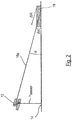
- Fig. 2
- eine schematische Darstellung einer auf einen Boden ausgerichteten optoelektronischen Sensorvorrichtung mit einem auf dem Boden angeordneten flachen Objekt zeigt;
- Fig. 3
- eine drehbare Sensorplatine mit vier Abstandssensoren zeigt;
- Fig. 4
- eine schematische Darstellung von vier erwarteten Bodenbereichen zeigt.
- Fig. 1
- shows a vehicle with an optoelectronic sensor device according to the invention;
- Fig. 2
- shows a schematic representation of a ground-oriented optoelectronic sensor device with a flat object arranged on the ground;
- Fig. 3
- shows a rotatable sensor board with four distance sensors;
- Fig. 4
- a schematic representation of four expected floor areas shows.
In den Zeichnungen sind identische oder ähnliche Teile mit denselben Bezugszeichen versehen.In the drawings, identical or similar parts are given the same reference numerals.
Ein Fahrzeug 10, das vorzugsweise selbstfahrend ist, weist eine optoelektronische Sensorvorrichtung 12 auf, die einen auf einen Boden 14 ausgerichteten Abstandssensor umfasst (
Der Abstandssensor der Sensorvorrichtung 12 ermittelt Abstandsinformationen für vier Überwachungsbereiche 16a, 16b, 16c, 16d, die jeweils einen Bereich des Bodens 14 abdecken. Die für jeden Überwachungsbereich 16a, 16b, 16c, 16d ermittelten Abstandsinformationen werden mit einem jeweiligen erwarteten Bodenbereich verglichen, wobei im Falle einer Abweichung ein Objekt und/oder eine Bodenanomalie erkannt wird. In
In ![]()
![]()
Ferner kann der Einfluss einer Veränderung des Winkels α auf die Abstandsänderung wie folgt angegeben werden: ![]()
![]()
In
- 1010
- Fahrzeugvehicle
- 1212
- Sensorvorrichtungsensor device
- 1414
- Bodenground
- 16a, 16b16a, 16b
- Überwachungsbereichmonitoring area
- 16c, 16d16c, 16d
- Überwachungsbereichmonitoring area
- 1818
- Objektobject
- 2020
- Sensorplatinesensor board
- 22a, 22b22a, 22b
- Lasersensorlaser sensor
- 22c, 22d22c, 22d
- Lasersensorlaser sensor
- 2424
- Hilfslinieledger line
- 2626
- Laserstrahllaser beam
- 28a, 28b28a, 28b
- erwarteter Bodenbereichexpected floor area
- 28c, 28d28c, 28d
- erwarteter Bodenbereichexpected floor area
- 3030
- Abstandspunktedistance points
- 3232
- Abstandspunktedistance points
- SS
- Achseaxis
Claims (15)
wobei das Modell ein geometrisches Modell ist, das nicht von Abstandsinformationen abhängig ist, die von dem Abstandssensor in einem tatsächlichen Betrieb der optoelektronischen Sensorvorrichtung (12) ermittelt werden.Optoelectronic sensor device according to claim 1,
wherein the model is a geometric model that does not depend on distance information determined by the distance sensor in actual operation of the optoelectronic sensor device (12).
wobei der zumindest eine Überwachungsbereich (16a, 16b, 16c, 16d) und der Boden einen Winkel α einschließen, der kleiner vierzig, vorzugsweise kleiner dreißig Grad ist.Optoelectronic sensor device according to claim 1 or 2,
wherein the at least one monitoring region (16a, 16b, 16c, 16d) and the bottom enclose an angle α that is less than forty, preferably less than thirty degrees.
wobei das Modell zumindest eine Referenzabstandskontur umfasst, die auf der Referenzlage und dem Referenzboden beruht,
und wobei der zumindest eine erwartete Bodenbereich (28a, 28b, 28c, 28d) einen Toleranzbereich um die zumindest eine Referenzabstandskontur bildet.Optoelectronic sensor device according to one of the preceding claims,
the model comprising at least one reference distance contour based on the reference position and the reference bottom,
and wherein the at least one expected bottom region (28a, 28b, 28c, 28d) forms a tolerance range around the at least one reference distance contour.
wobei der zumindest eine Überwachungsbereich eine ebene und/oder gekrümmte Fläche umfasst, die sich zumindest teilweise mit dem Referenzboden schneidet, wobei die Schnittlinie zwischen der Fläche und dem Referenzboden die zumindest eine Referenzabstandskontur bildet.Optoelectronic sensor device according to claim 4,
wherein the at least one monitoring region comprises a planar and / or curved surface which intersects at least partially with the reference bottom, the cutting line between the surface and the reference bottom forming the at least one reference spacing contour.
wobei die Auswerteeinheit dazu ausgebildet ist, den zumindest einen erwarteten Bodenbereich auf der Grundlage des vordefinierten Modells zu bestimmen.Optoelectronic sensor device according to one of the preceding claims,
wherein the evaluation unit is configured to determine the at least one expected floor area on the basis of the predefined model.
wobei die Auswerteeinheit dazu ausgebildet ist, den zumindest einen erwarteten Bodenbereich (28a, 28b, 28c, 28d) in Abhängigkeit von aktuell ermittelten Abstandsinformationen anzupassen.Optoelectronic sensor device according to one of the preceding claims,
wherein the evaluation unit is designed to adapt the at least one expected floor area (28a, 28b, 28c, 28d) as a function of currently determined distance information.
wobei die ermittelten Abstandsinformationen mehrere Abstandspunkte (30, 32) umfassen, wobei die Auswerteeinheit dazu ausgebildet ist, den erwarteten Bodenbereich (28a, 28b, 28c, 28d) in Abhängigkeit einer Untermenge der mehreren Abstandspunkte anzupassen, wobei die Untermenge der mehreren Abstandspunkte Abstandspunkte (30, 32) der ermittelten Abstandsinformationen umfasst, die
und/oder
und/oder
wherein the determined distance information comprises a plurality of distance points (30, 32), wherein the evaluation unit is adapted to adapt the expected floor area (28a, 28b, 28c, 28d) in dependence on a subset of the plurality of distance points, wherein the subset of the plurality of distance point distance points (30 , 32) comprises the determined distance information, the
and or
and or
wobei der Abstandssensor Abstandsinformationen für zwei bis sechs, vorzugsweise vier Überwachungsbereiche (16a, 16b, 16c, 16d) ermittelt, wobei jeder der Überwachungsbereiche (16a, 16b, 16c, 16d) jeweils einen Bodenbereich abdeckt, der einen Oberflächenbereich des Bodens (14) bildet, wobei die abgedeckten Bodenreiche vorzugsweise voneinander beabstandet sind.Optoelectronic sensor device according to one of the preceding claims,
wherein the distance sensor determines distance information for two to six, preferably four monitoring areas (16a, 16b, 16c, 16d), each of the monitored areas (16a, 16b, 16c, 16d) each covering a floor area forming a surface area of the floor (14) wherein the covered soil regions are preferably spaced apart from each other.
wobei die Auswerteeinheit dazu angepasst ist, eine Lage des Abstandssensors zu ermitteln.Optoelectronic sensor device according to one of the preceding claims,
wherein the evaluation unit is adapted to determine a position of the distance sensor.
wobei die Auswerteeinheit eine Recheneinrichtung des Abstandssensors ist, wobei eine Datenverarbeitung des Abstandssensors vollständig oder teilweise im Abstandssensor stattfindet.Optoelectronic sensor device according to one of the preceding claims,
wherein the evaluation unit is a computing device of the distance sensor, wherein a data processing of the distance sensor takes place completely or partially in the distance sensor.
wobei die Auswerteeinheit ausgebildet ist, das vordefinierte Modell an beschleunigungsabhängige Bewegungen des Fahrzeugs (12) anzupassen.Vehicle (12) according to claim 12,
wherein the evaluation unit is designed to adapt the predefined model to acceleration-dependent movements of the vehicle (12).
wobei das Fahrzeug (12) selbstfahrend ist.Vehicle (12) according to claim 9 or 10,
wherein the vehicle (12) is self-propelled.
Applications Claiming Priority (1)
| Application Number | Priority Date | Filing Date | Title |
|---|---|---|---|
| DE102018102287.5A DE102018102287A1 (en) | 2018-02-01 | 2018-02-01 | Optoelectronic sensor device |
Publications (2)
| Publication Number | Publication Date |
|---|---|
| EP3521860A1 true EP3521860A1 (en) | 2019-08-07 |
| EP3521860B1 EP3521860B1 (en) | 2020-12-16 |
Family
ID=65013582
Family Applications (1)
| Application Number | Title | Priority Date | Filing Date |
|---|---|---|---|
| EP19151190.6A Active EP3521860B1 (en) | 2018-02-01 | 2019-01-10 | Opto-electronic sensor device |
Country Status (2)
| Country | Link |
|---|---|
| EP (1) | EP3521860B1 (en) |
| DE (1) | DE102018102287A1 (en) |
Cited By (1)
| Publication number | Priority date | Publication date | Assignee | Title |
|---|---|---|---|---|
| EP4109127A1 (en) | 2021-06-21 | 2022-12-28 | Sick Ag | Optoelectronic sensor and method for detecting objects |
Families Citing this family (1)
| Publication number | Priority date | Publication date | Assignee | Title |
|---|---|---|---|---|
| DE102019217988A1 (en) * | 2019-11-21 | 2021-05-27 | Zf Friedrichshafen Ag | Camera-based detection of tilting movements |
Citations (3)
| Publication number | Priority date | Publication date | Assignee | Title |
|---|---|---|---|---|
| EP2192384A1 (en) * | 2008-11-27 | 2010-06-02 | DS Automation GmbH | Device and method for optical position determination of a vehicle |
| US7741961B1 (en) * | 2006-09-29 | 2010-06-22 | Canesta, Inc. | Enhanced obstacle detection and tracking for three-dimensional imaging systems used in motor vehicles |
| DE102013207147A1 (en) * | 2012-05-03 | 2013-11-07 | Ifm Electronic Gmbh | Road surface profile detecting system for motor car, has time-of-flight cameras which detect road surface profile and determine distance and dimension of irregularities in overlapping monitored areas of cameras |
Family Cites Families (2)
| Publication number | Priority date | Publication date | Assignee | Title |
|---|---|---|---|---|
| DE102011080932A1 (en) * | 2011-08-12 | 2013-02-14 | Robert Bosch Gmbh | Method for assisting driver of vehicle during execution of driving maneuver, involves providing environmental data and evaluating environmental data, where ground level objects are identified |
| DE102014217352B4 (en) * | 2014-08-29 | 2018-04-19 | HAP Handhabungs-, Automatisierungs- und Präzisionstechnik GmbH | Mobile device for manipulating objects |
-
2018
- 2018-02-01 DE DE102018102287.5A patent/DE102018102287A1/en not_active Withdrawn
-
2019
- 2019-01-10 EP EP19151190.6A patent/EP3521860B1/en active Active
Patent Citations (3)
| Publication number | Priority date | Publication date | Assignee | Title |
|---|---|---|---|---|
| US7741961B1 (en) * | 2006-09-29 | 2010-06-22 | Canesta, Inc. | Enhanced obstacle detection and tracking for three-dimensional imaging systems used in motor vehicles |
| EP2192384A1 (en) * | 2008-11-27 | 2010-06-02 | DS Automation GmbH | Device and method for optical position determination of a vehicle |
| DE102013207147A1 (en) * | 2012-05-03 | 2013-11-07 | Ifm Electronic Gmbh | Road surface profile detecting system for motor car, has time-of-flight cameras which detect road surface profile and determine distance and dimension of irregularities in overlapping monitored areas of cameras |
Cited By (2)
| Publication number | Priority date | Publication date | Assignee | Title |
|---|---|---|---|---|
| EP4109127A1 (en) | 2021-06-21 | 2022-12-28 | Sick Ag | Optoelectronic sensor and method for detecting objects |
| JP2023001875A (en) * | 2021-06-21 | 2023-01-06 | ジック アーゲー | Photoelectric sensor and object detection method |
Also Published As
| Publication number | Publication date |
|---|---|
| EP3521860B1 (en) | 2020-12-16 |
| DE102018102287A1 (en) | 2019-08-01 |
Similar Documents
| Publication | Publication Date | Title |
|---|---|---|
| EP1643271B1 (en) | Method and device for classifying side boundaries of a parking space for a parking assistance system of a motor vehicle | |
| EP3435117B1 (en) | Sensor and method for detecting and determining the distance between objects | |
| EP1927867A1 (en) | Optoelectronic multiple plane sensor and method for detecting objects | |
| EP2339376A1 (en) | Optoelectronic sensor | |
| EP1286178A2 (en) | Method for optical ground detection | |
| DE19832790A1 (en) | Obstacle detection system for vehicle | |
| DE102008032216A1 (en) | Device for detecting the presence of an object in space | |
| EP1068992A2 (en) | Device for assisting reversing | |
| EP3521860B1 (en) | Opto-electronic sensor device | |
| WO2011098608A1 (en) | Marking device and system for surveying land | |
| EP3738420B1 (en) | Method for operating a self-propelled agricultural working machine | |
| DE10033608A1 (en) | Securing an area around a machine tool to prevent entrance of personnel and possible injury using artificial light target, the image of which can be compared to a reference value and used to switch off the machine | |
| EP1508818A1 (en) | Method of operating a radar sensor | |
| EP1224644B1 (en) | Device for controlling the flow of traffic at a crossroads, especially for controlling traffic lights | |
| EP3026459B1 (en) | Sensor system | |
| DE202014105727U1 (en) | sensor system | |
| EP3710905B1 (en) | Infrastructure system | |
| EP3990944A1 (en) | Determining a pitch angle position of an active optical sensor system | |
| DE102021112709B4 (en) | LiDAR laser scanner | |
| WO2022248479A1 (en) | Method and device for recognizing blocking of a lidar system, and corresponding vehicle | |
| EP4127767B1 (en) | Object recognition by an active optical sensor system | |
| DE202020106363U1 (en) | Vehicle and device for carrying out a method for avoiding a collision of a vehicle with an obstacle | |
| DE102021213080A1 (en) | Apparatus for a construction site marker to detect an area violation | |
| EP3913179A1 (en) | Automatic window or door installation | |
| DE102020129233A1 (en) | Vehicle and method for avoiding a collision of a vehicle with an obstacle |
Legal Events
| Date | Code | Title | Description |
|---|---|---|---|
| PUAI | Public reference made under article 153(3) epc to a published international application that has entered the european phase |
Free format text: ORIGINAL CODE: 0009012 |
|
| STAA | Information on the status of an ep patent application or granted ep patent |
Free format text: STATUS: THE APPLICATION HAS BEEN PUBLISHED |
|
| AK | Designated contracting states |
Kind code of ref document: A1 Designated state(s): AL AT BE BG CH CY CZ DE DK EE ES FI FR GB GR HR HU IE IS IT LI LT LU LV MC MK MT NL NO PL PT RO RS SE SI SK SM TR |
|
| AX | Request for extension of the european patent |
Extension state: BA ME |
|
| STAA | Information on the status of an ep patent application or granted ep patent |
Free format text: STATUS: REQUEST FOR EXAMINATION WAS MADE |
|
| RAP1 | Party data changed (applicant data changed or rights of an application transferred) |
Owner name: SICK AG |
|
| 17P | Request for examination filed |
Effective date: 20200204 |
|
| RBV | Designated contracting states (corrected) |
Designated state(s): AL AT BE BG CH CY CZ DE DK EE ES FI FR GB GR HR HU IE IS IT LI LT LU LV MC MK MT NL NO PL PT RO RS SE SI SK SM TR |
|
| STAA | Information on the status of an ep patent application or granted ep patent |
Free format text: STATUS: EXAMINATION IS IN PROGRESS |
|
| 17Q | First examination report despatched |
Effective date: 20200326 |
|
| REG | Reference to a national code |
Ref country code: DE Ref legal event code: R079 Ref document number: 502019000513 Country of ref document: DE Free format text: PREVIOUS MAIN CLASS: G01S0017930000 Ipc: G01S0017420000 |
|
| GRAP | Despatch of communication of intention to grant a patent |
Free format text: ORIGINAL CODE: EPIDOSNIGR1 |
|
| STAA | Information on the status of an ep patent application or granted ep patent |
Free format text: STATUS: GRANT OF PATENT IS INTENDED |
|
| GRAJ | Information related to disapproval of communication of intention to grant by the applicant or resumption of examination proceedings by the epo deleted |
Free format text: ORIGINAL CODE: EPIDOSDIGR1 |
|
| RIC1 | Information provided on ipc code assigned before grant |
Ipc: G01S 17/931 20200101ALI20200608BHEP Ipc: G01S 17/87 20200101ALI20200608BHEP Ipc: G01S 7/48 20060101ALI20200608BHEP Ipc: G01S 17/42 20060101AFI20200608BHEP |
|
| STAA | Information on the status of an ep patent application or granted ep patent |
Free format text: STATUS: EXAMINATION IS IN PROGRESS |
|
| INTG | Intention to grant announced |
Effective date: 20200703 |
|
| GRAP | Despatch of communication of intention to grant a patent |
Free format text: ORIGINAL CODE: EPIDOSNIGR1 |
|
| STAA | Information on the status of an ep patent application or granted ep patent |
Free format text: STATUS: GRANT OF PATENT IS INTENDED |
|
| INTC | Intention to grant announced (deleted) | ||
| INTG | Intention to grant announced |
Effective date: 20200817 |
|
| GRAS | Grant fee paid |
Free format text: ORIGINAL CODE: EPIDOSNIGR3 |
|
| GRAA | (expected) grant |
Free format text: ORIGINAL CODE: 0009210 |
|
| STAA | Information on the status of an ep patent application or granted ep patent |
Free format text: STATUS: THE PATENT HAS BEEN GRANTED |
|
| AK | Designated contracting states |
Kind code of ref document: B1 Designated state(s): AL AT BE BG CH CY CZ DE DK EE ES FI FR GB GR HR HU IE IS IT LI LT LU LV MC MK MT NL NO PL PT RO RS SE SI SK SM TR |
|
| REG | Reference to a national code |
Ref country code: GB Ref legal event code: FG4D Free format text: NOT ENGLISH |
|
| REG | Reference to a national code |
Ref country code: DE Ref legal event code: R096 Ref document number: 502019000513 Country of ref document: DE |
|
| REG | Reference to a national code |
Ref country code: IE Ref legal event code: FG4D Free format text: LANGUAGE OF EP DOCUMENT: GERMAN |
|
| REG | Reference to a national code |
Ref country code: AT Ref legal event code: REF Ref document number: 1346099 Country of ref document: AT Kind code of ref document: T Effective date: 20210115 |
|
| PG25 | Lapsed in a contracting state [announced via postgrant information from national office to epo] |
Ref country code: NO Free format text: LAPSE BECAUSE OF FAILURE TO SUBMIT A TRANSLATION OF THE DESCRIPTION OR TO PAY THE FEE WITHIN THE PRESCRIBED TIME-LIMIT Effective date: 20210316 Ref country code: GR Free format text: LAPSE BECAUSE OF FAILURE TO SUBMIT A TRANSLATION OF THE DESCRIPTION OR TO PAY THE FEE WITHIN THE PRESCRIBED TIME-LIMIT Effective date: 20210317 Ref country code: RS Free format text: LAPSE BECAUSE OF FAILURE TO SUBMIT A TRANSLATION OF THE DESCRIPTION OR TO PAY THE FEE WITHIN THE PRESCRIBED TIME-LIMIT Effective date: 20201216 Ref country code: FI Free format text: LAPSE BECAUSE OF FAILURE TO SUBMIT A TRANSLATION OF THE DESCRIPTION OR TO PAY THE FEE WITHIN THE PRESCRIBED TIME-LIMIT Effective date: 20201216 |
|
| REG | Reference to a national code |
Ref country code: NL Ref legal event code: MP Effective date: 20201216 |
|
| PG25 | Lapsed in a contracting state [announced via postgrant information from national office to epo] |
Ref country code: SE Free format text: LAPSE BECAUSE OF FAILURE TO SUBMIT A TRANSLATION OF THE DESCRIPTION OR TO PAY THE FEE WITHIN THE PRESCRIBED TIME-LIMIT Effective date: 20201216 Ref country code: LV Free format text: LAPSE BECAUSE OF FAILURE TO SUBMIT A TRANSLATION OF THE DESCRIPTION OR TO PAY THE FEE WITHIN THE PRESCRIBED TIME-LIMIT Effective date: 20201216 Ref country code: BG Free format text: LAPSE BECAUSE OF FAILURE TO SUBMIT A TRANSLATION OF THE DESCRIPTION OR TO PAY THE FEE WITHIN THE PRESCRIBED TIME-LIMIT Effective date: 20210316 |
|
| PG25 | Lapsed in a contracting state [announced via postgrant information from national office to epo] |
Ref country code: NL Free format text: LAPSE BECAUSE OF FAILURE TO SUBMIT A TRANSLATION OF THE DESCRIPTION OR TO PAY THE FEE WITHIN THE PRESCRIBED TIME-LIMIT Effective date: 20201216 Ref country code: HR Free format text: LAPSE BECAUSE OF FAILURE TO SUBMIT A TRANSLATION OF THE DESCRIPTION OR TO PAY THE FEE WITHIN THE PRESCRIBED TIME-LIMIT Effective date: 20201216 |
|
| REG | Reference to a national code |
Ref country code: LT Ref legal event code: MG9D |
|
| PG25 | Lapsed in a contracting state [announced via postgrant information from national office to epo] |
Ref country code: EE Free format text: LAPSE BECAUSE OF FAILURE TO SUBMIT A TRANSLATION OF THE DESCRIPTION OR TO PAY THE FEE WITHIN THE PRESCRIBED TIME-LIMIT Effective date: 20201216 Ref country code: CZ Free format text: LAPSE BECAUSE OF FAILURE TO SUBMIT A TRANSLATION OF THE DESCRIPTION OR TO PAY THE FEE WITHIN THE PRESCRIBED TIME-LIMIT Effective date: 20201216 Ref country code: SK Free format text: LAPSE BECAUSE OF FAILURE TO SUBMIT A TRANSLATION OF THE DESCRIPTION OR TO PAY THE FEE WITHIN THE PRESCRIBED TIME-LIMIT Effective date: 20201216 Ref country code: SM Free format text: LAPSE BECAUSE OF FAILURE TO SUBMIT A TRANSLATION OF THE DESCRIPTION OR TO PAY THE FEE WITHIN THE PRESCRIBED TIME-LIMIT Effective date: 20201216 Ref country code: LT Free format text: LAPSE BECAUSE OF FAILURE TO SUBMIT A TRANSLATION OF THE DESCRIPTION OR TO PAY THE FEE WITHIN THE PRESCRIBED TIME-LIMIT Effective date: 20201216 Ref country code: PT Free format text: LAPSE BECAUSE OF FAILURE TO SUBMIT A TRANSLATION OF THE DESCRIPTION OR TO PAY THE FEE WITHIN THE PRESCRIBED TIME-LIMIT Effective date: 20210416 Ref country code: RO Free format text: LAPSE BECAUSE OF FAILURE TO SUBMIT A TRANSLATION OF THE DESCRIPTION OR TO PAY THE FEE WITHIN THE PRESCRIBED TIME-LIMIT Effective date: 20201216 |
|
| PG25 | Lapsed in a contracting state [announced via postgrant information from national office to epo] |
Ref country code: PL Free format text: LAPSE BECAUSE OF FAILURE TO SUBMIT A TRANSLATION OF THE DESCRIPTION OR TO PAY THE FEE WITHIN THE PRESCRIBED TIME-LIMIT Effective date: 20201216 |
|
| REG | Reference to a national code |
Ref country code: DE Ref legal event code: R097 Ref document number: 502019000513 Country of ref document: DE |
|
| PG25 | Lapsed in a contracting state [announced via postgrant information from national office to epo] |
Ref country code: IS Free format text: LAPSE BECAUSE OF FAILURE TO SUBMIT A TRANSLATION OF THE DESCRIPTION OR TO PAY THE FEE WITHIN THE PRESCRIBED TIME-LIMIT Effective date: 20210416 Ref country code: MC Free format text: LAPSE BECAUSE OF FAILURE TO SUBMIT A TRANSLATION OF THE DESCRIPTION OR TO PAY THE FEE WITHIN THE PRESCRIBED TIME-LIMIT Effective date: 20201216 Ref country code: LU Free format text: LAPSE BECAUSE OF NON-PAYMENT OF DUE FEES Effective date: 20210110 |
|
| REG | Reference to a national code |
Ref country code: BE Ref legal event code: MM Effective date: 20210131 |
|
| PLBE | No opposition filed within time limit |
Free format text: ORIGINAL CODE: 0009261 |
|
| STAA | Information on the status of an ep patent application or granted ep patent |
Free format text: STATUS: NO OPPOSITION FILED WITHIN TIME LIMIT |
|
| PG25 | Lapsed in a contracting state [announced via postgrant information from national office to epo] |
Ref country code: AL Free format text: LAPSE BECAUSE OF FAILURE TO SUBMIT A TRANSLATION OF THE DESCRIPTION OR TO PAY THE FEE WITHIN THE PRESCRIBED TIME-LIMIT Effective date: 20201216 Ref country code: IT Free format text: LAPSE BECAUSE OF FAILURE TO SUBMIT A TRANSLATION OF THE DESCRIPTION OR TO PAY THE FEE WITHIN THE PRESCRIBED TIME-LIMIT Effective date: 20201216 |
|
| 26N | No opposition filed |
Effective date: 20210917 |
|
| PG25 | Lapsed in a contracting state [announced via postgrant information from national office to epo] |
Ref country code: DK Free format text: LAPSE BECAUSE OF FAILURE TO SUBMIT A TRANSLATION OF THE DESCRIPTION OR TO PAY THE FEE WITHIN THE PRESCRIBED TIME-LIMIT Effective date: 20201216 |
|
| PG25 | Lapsed in a contracting state [announced via postgrant information from national office to epo] |
Ref country code: IE Free format text: LAPSE BECAUSE OF NON-PAYMENT OF DUE FEES Effective date: 20210110 Ref country code: ES Free format text: LAPSE BECAUSE OF FAILURE TO SUBMIT A TRANSLATION OF THE DESCRIPTION OR TO PAY THE FEE WITHIN THE PRESCRIBED TIME-LIMIT Effective date: 20201216 |
|
| PG25 | Lapsed in a contracting state [announced via postgrant information from national office to epo] |
Ref country code: SI Free format text: LAPSE BECAUSE OF FAILURE TO SUBMIT A TRANSLATION OF THE DESCRIPTION OR TO PAY THE FEE WITHIN THE PRESCRIBED TIME-LIMIT Effective date: 20201216 |
|
| PG25 | Lapsed in a contracting state [announced via postgrant information from national office to epo] |
Ref country code: IS Free format text: LAPSE BECAUSE OF FAILURE TO SUBMIT A TRANSLATION OF THE DESCRIPTION OR TO PAY THE FEE WITHIN THE PRESCRIBED TIME-LIMIT Effective date: 20210416 |
|
| PG25 | Lapsed in a contracting state [announced via postgrant information from national office to epo] |
Ref country code: BE Free format text: LAPSE BECAUSE OF NON-PAYMENT OF DUE FEES Effective date: 20210131 |
|
| REG | Reference to a national code |
Ref country code: CH Ref legal event code: PL |
|
| PG25 | Lapsed in a contracting state [announced via postgrant information from national office to epo] |
Ref country code: LI Free format text: LAPSE BECAUSE OF NON-PAYMENT OF DUE FEES Effective date: 20220131 Ref country code: CH Free format text: LAPSE BECAUSE OF NON-PAYMENT OF DUE FEES Effective date: 20220131 |
|
| PGFP | Annual fee paid to national office [announced via postgrant information from national office to epo] |
Ref country code: FR Payment date: 20230123 Year of fee payment: 5 |
|
| PGFP | Annual fee paid to national office [announced via postgrant information from national office to epo] |
Ref country code: DE Payment date: 20230119 Year of fee payment: 5 |
|
| PG25 | Lapsed in a contracting state [announced via postgrant information from national office to epo] |
Ref country code: CY Free format text: LAPSE BECAUSE OF FAILURE TO SUBMIT A TRANSLATION OF THE DESCRIPTION OR TO PAY THE FEE WITHIN THE PRESCRIBED TIME-LIMIT Effective date: 20201216 |
|
| PG25 | Lapsed in a contracting state [announced via postgrant information from national office to epo] |
Ref country code: HU Free format text: LAPSE BECAUSE OF FAILURE TO SUBMIT A TRANSLATION OF THE DESCRIPTION OR TO PAY THE FEE WITHIN THE PRESCRIBED TIME-LIMIT; INVALID AB INITIO Effective date: 20190110 |
|
| GBPC | Gb: european patent ceased through non-payment of renewal fee |
Effective date: 20230110 |
|
| PG25 | Lapsed in a contracting state [announced via postgrant information from national office to epo] |
Ref country code: GB Free format text: LAPSE BECAUSE OF NON-PAYMENT OF DUE FEES Effective date: 20230110 |