EP3521774A1 - Dispositif de mesure d'écoulement à ultrasons et procédé de détermination de la vitesse d'écoulement - Google Patents
Dispositif de mesure d'écoulement à ultrasons et procédé de détermination de la vitesse d'écoulement Download PDFInfo
- Publication number
- EP3521774A1 EP3521774A1 EP18155305.8A EP18155305A EP3521774A1 EP 3521774 A1 EP3521774 A1 EP 3521774A1 EP 18155305 A EP18155305 A EP 18155305A EP 3521774 A1 EP3521774 A1 EP 3521774A1
- Authority
- EP
- European Patent Office
- Prior art keywords
- ultrasonic
- flow
- paths
- transit time
- measurement
- Prior art date
- Legal status (The legal status is an assumption and is not a legal conclusion. Google has not performed a legal analysis and makes no representation as to the accuracy of the status listed.)
- Granted
Links
- 238000002604 ultrasonography Methods 0.000 title claims abstract description 14
- 238000000034 method Methods 0.000 title claims description 18
- 239000012530 fluid Substances 0.000 claims abstract description 81
- 238000011156 evaluation Methods 0.000 claims abstract description 20
- 238000005259 measurement Methods 0.000 claims description 81
- 230000006978 adaptation Effects 0.000 claims description 5
- 239000012528 membrane Substances 0.000 claims description 4
- 230000005484 gravity Effects 0.000 claims description 3
- 230000010355 oscillation Effects 0.000 description 20
- 230000000694 effects Effects 0.000 description 11
- 230000008901 benefit Effects 0.000 description 7
- 230000009897 systematic effect Effects 0.000 description 5
- 230000008859 change Effects 0.000 description 4
- 238000013016 damping Methods 0.000 description 4
- 238000009434 installation Methods 0.000 description 3
- 230000005855 radiation Effects 0.000 description 3
- 239000000523 sample Substances 0.000 description 2
- 238000004088 simulation Methods 0.000 description 2
- 238000012935 Averaging Methods 0.000 description 1
- 238000013459 approach Methods 0.000 description 1
- 238000004364 calculation method Methods 0.000 description 1
- 239000000919 ceramic Substances 0.000 description 1
- 238000012937 correction Methods 0.000 description 1
- 230000008878 coupling Effects 0.000 description 1
- 238000010168 coupling process Methods 0.000 description 1
- 238000005859 coupling reaction Methods 0.000 description 1
- 230000006735 deficit Effects 0.000 description 1
- 230000001419 dependent effect Effects 0.000 description 1
- 238000013461 design Methods 0.000 description 1
- 239000006185 dispersion Substances 0.000 description 1
- 238000006073 displacement reaction Methods 0.000 description 1
- 230000009977 dual effect Effects 0.000 description 1
- 230000005284 excitation Effects 0.000 description 1
- 230000002349 favourable effect Effects 0.000 description 1
- 238000012986 modification Methods 0.000 description 1
- 230000004048 modification Effects 0.000 description 1
- 230000008569 process Effects 0.000 description 1
- 238000012545 processing Methods 0.000 description 1
- 230000001902 propagating effect Effects 0.000 description 1
- 238000005070 sampling Methods 0.000 description 1
- 230000005236 sound signal Effects 0.000 description 1
Images


Classifications
-
- G—PHYSICS
- G01—MEASURING; TESTING
- G01F—MEASURING VOLUME, VOLUME FLOW, MASS FLOW OR LIQUID LEVEL; METERING BY VOLUME
- G01F1/00—Measuring the volume flow or mass flow of fluid or fluent solid material wherein the fluid passes through a meter in a continuous flow
- G01F1/66—Measuring the volume flow or mass flow of fluid or fluent solid material wherein the fluid passes through a meter in a continuous flow by measuring frequency, phase shift or propagation time of electromagnetic or other waves, e.g. using ultrasonic flowmeters
- G01F1/662—Constructional details
-
- G—PHYSICS
- G01—MEASURING; TESTING
- G01F—MEASURING VOLUME, VOLUME FLOW, MASS FLOW OR LIQUID LEVEL; METERING BY VOLUME
- G01F1/00—Measuring the volume flow or mass flow of fluid or fluent solid material wherein the fluid passes through a meter in a continuous flow
- G01F1/66—Measuring the volume flow or mass flow of fluid or fluent solid material wherein the fluid passes through a meter in a continuous flow by measuring frequency, phase shift or propagation time of electromagnetic or other waves, e.g. using ultrasonic flowmeters
- G01F1/667—Arrangements of transducers for ultrasonic flowmeters; Circuits for operating ultrasonic flowmeters
-
- G—PHYSICS
- G01—MEASURING; TESTING
- G01F—MEASURING VOLUME, VOLUME FLOW, MASS FLOW OR LIQUID LEVEL; METERING BY VOLUME
- G01F1/00—Measuring the volume flow or mass flow of fluid or fluent solid material wherein the fluid passes through a meter in a continuous flow
- G01F1/66—Measuring the volume flow or mass flow of fluid or fluent solid material wherein the fluid passes through a meter in a continuous flow by measuring frequency, phase shift or propagation time of electromagnetic or other waves, e.g. using ultrasonic flowmeters
-
- G—PHYSICS
- G01—MEASURING; TESTING
- G01P—MEASURING LINEAR OR ANGULAR SPEED, ACCELERATION, DECELERATION, OR SHOCK; INDICATING PRESENCE, ABSENCE, OR DIRECTION, OF MOVEMENT
- G01P5/00—Measuring speed of fluids, e.g. of air stream; Measuring speed of bodies relative to fluids, e.g. of ship, of aircraft
- G01P5/24—Measuring speed of fluids, e.g. of air stream; Measuring speed of bodies relative to fluids, e.g. of ship, of aircraft by measuring the direct influence of the streaming fluid on the properties of a detecting acoustical wave
- G01P5/245—Measuring speed of fluids, e.g. of air stream; Measuring speed of bodies relative to fluids, e.g. of ship, of aircraft by measuring the direct influence of the streaming fluid on the properties of a detecting acoustical wave by measuring transit time of acoustical waves
Definitions
- the invention relates to an ultrasonic flow measuring device and a method for determining the flow velocity of a fluid flowing in a conduit according to the preamble of claims 1 and 13, respectively.
- a proven method of measuring flow velocity or flow is the differential transit time method.
- a pair of ultrasonic transducers is mounted on the outer circumference of the pipeline with a mutual offset in the longitudinal direction, which transmit and register mutually ultrasound signals transversely to the flow along the measurement path spanned between the ultrasonic transducers.
- the ultrasonic signals transported by the fluid are accelerated or decelerated by the flow depending on the direction of travel.
- the resulting transit time difference is calculated with geometric variables to an average flow velocity of the fluid. With the cross-sectional area, this results in the volume flow or flow.
- multiple measurement paths, each with a pair of ultrasonic transducers may be provided to more accurately detect a flow area.
- the ultrasonic transducers used to generate the ultrasound have a vibrating body, often a ceramic. With its help, for example, based on the piezoelectric effect, an electrical signal is converted into ultrasound and vice versa.
- the ultrasonic transducer works as a sound source, sound detector or both. It must be ensured for a coupling between the fluid and the ultrasonic transducer.
- a common solution is to introduce the ultrasonic transducers into the conduit in direct contact with the fluid. However, such intrusive probes can provide accurate measurements by disturbing the flow difficult. Conversely, the immersing ultrasonic transducers are exposed to the fluid and its pressure and temperature, and thus may be damaged or lose their function due to deposits.
- the EP 1 378 272 B1 suggests to attach the ultrasound generating elements to an outside of a wall.
- the ultrasonic transducer is integrated into the wall.
- a pocket with considerably smaller wall thickness than the remaining wall is formed, and the remaining wall thickness forms the membrane of the ultrasonic transducer.
- This assembly also referred to as clamp-in, is to a certain extent an intermediate form of the fixed assembly in the interior of the line and the clamp-on mounting.
- the ultrasonic transducers In addition to the fluid sound, the ultrasonic transducers also always generate body or structural sound transmitted through the conduit wall.
- the structure sound is a disturbance, because it remains unaffected by the fluid and its flow, so does not contain the desired measurement information, and is superimposed on the measurement signal in time.
- the structural sound can be minimized by constructive damping structures that acoustically decouple the ultrasonic transducer from the line. This is no longer possible in a clamp-on or clamp-in installation, in which ultrasonic signals are transmitted through the conduit wall or even deliberately excite a part of the conduit wall.
- Structural sound can not be separated from the fluid sound by classical algorithmic filter methods, since the frequencies of structure and fluid sound coincide.
- the DE 20 2013 105 800 U1 discloses an ultrasonic measuring device with ultrasonic transducers in clamp-in mounting.
- damping areas with scattering centers for example in the form of welds, are provided in the conduit wall. But this is the disturbing effect At best, reduce structure noise a little, basically the problem persists.
- the ultrasonic flow measuring device is in principle a multi-path counter and accordingly measures with a differential transit time method at a plurality of measuring paths, which are each clamped by two ultrasonic transducers.
- the ultrasonic transducers of a measuring path are arranged at diametrically or radially offset opposite line walls, so that the measuring paths run through the fluid.
- the ultrasonic transducers with an axial distance, ie in the longitudinal direction of the line, offset from one another, so that the course of the measuring path has a component with and against the flow.
- the flow velocity is calculated from runtime differences along the multiple measurement paths.
- the invention is based on the basic idea of not laying the multiple paths in the same cross-sectional plane as usual in a multipath counter, but instead of giving them a different axial offset.
- a conventional multipath counter attempts to more accurately measure uneven flow by multiple scanning of the same cross-section at multiple locations.
- it is a question of creating measuring paths in which the ratio of the propagation paths for fluid sound and structural sound varies, and this with the same flow behavior as possible for these measuring paths. This creates the prerequisite for compensating the effects of structural noise in the evaluation. This variation is achieved over the axial distance.
- the invention has the advantage that a much more accurate measurement becomes possible. Due to the special arrangement of ultrasonic transducers and measuring paths, in particular with an associated signal processing to be explained, the desired measurement signal is much better detectable, the influence of structural noise on the measurement of the transit time difference compensated and thus significantly reduces the systematic uncertainty of the flow measurement.
- the measuring paths are preferably arranged in a common plane parallel to the line. Such a plane can also be called a longitudinal plane. In a cross-sectional view, the measurement paths are thus superimposed, and they have the same secant angle, which describes the angular offset of a diametrical course. It should be emphasized again that the measurement paths are arranged differently than in a conventional multipath counter. Measurement paths in a common longitudinal plane scan virtually the same flow area, but at different axial distances. It would be conceivable to provide further groups of measurement paths in respective other longitudinal planes, with different axial distances within the group.
- the measuring paths are arranged directly behind one another.
- the aim of the arrangement of measuring paths according to the invention is to vary as far as possible only the axial distance.
- the other conditions and above all the flow behavior should ideally remain identical for these measurement paths. If one arranges the measuring paths as close as possible, i. in the longitudinal direction parallel to the conduit axis, this is at least approximately achieved because the flow on the short flow path therebetween practically does not change.
- the measuring paths preferably together form a sawtooth shape.
- a sawtooth or zig-zag shape is a particularly favorable arrangement which makes it possible to monitor very similar or practically identical flow sections in a compact measuring path layout.
- the saw teeth are not quite the same size, since the axial distance should be varied.
- Ultrasonic transducers at points of the sawtooth shape are preferably involved in both adjacent measuring paths. This can not of course apply to the two ultrasonic transducers on the edge, ie at the beginning and end of the sawtooth shape.
- the middle ultrasonic transducers can but with sufficiently large radiation angle measuring paths span in two directions, so that a total of less ultrasonic transducers are needed, namely in particular only n + 1 ultrasonic transducer for n measuring paths.
- the ultrasonic transducers are preferably actuated in a time-delayed manner, since otherwise the measurements would interfere with one another, so that the double use of an ultrasound transducer in two measuring paths means no additional restrictions.
- the evaluation unit is preferably designed to estimate at least one characteristic quantity of a function which describes the dependence of the transit time or transit time difference on the axial distance of the ultrasonic transducers from the multiple measurements on the plurality of measurement paths, and to calculate the flow velocity from the characteristic variable.
- the invention has recognized that an error caused by the superimposed structural sound in the measured propagation time difference varies with the axial distance of the ultrasonic transducers which span the respective measurement path.
- the transit time difference does not increase monotonically with the axial distance, but it forms an oscillation.
- the approach of the evaluation according to the invention is to consider the function of the transit time difference as a function of the axial distance and to correct the oscillation.
- the function is detected by the multiple measurement paths at several points, namely the multiple axial distances.
- the function can be estimated and the error compensated. It is not absolutely necessary to reconstruct the entire function, but initially only at least one characteristic quantity thereof, for example the slope of a straight line.
- the result is an improved measurement result, which is at least largely adjusted for systematic interference effects by structural noise.
- the underlying evaluation takes place at measurement level and is therefore compared to methods on signal level mathematically very simple and also extremely resource-conserving, since even the classical runtime measurement makes higher demands on the device hardware.
- the evaluation unit is preferably designed for a linear adaptation of the function.
- a linear adjustment is possible with relatively little effort, but is sufficient for the correction of the oscillation. So this is an example of a characteristic size of the function.
- the remaining residual error is significantly dependent on the number of measurement paths, resulting in a high scalability in terms of accuracy and cost of the ultrasonic flowmeter.
- the evaluation is risk-free, because even with unsuitable measuring path configurations in which, for example, all measuring paths have the same axial distance, the result is simply an averaging of the individual measurements.
- the evaluation unit is preferably designed to assume a vanishing transit time difference for the linear adjustment with vanishing axial distance.
- a vanishing transit time difference for the linear adjustment with vanishing axial distance.
- the evaluation unit is preferably designed to determine a compensated transit time or transit time difference from the linear adaptation at an axial distance, which corresponds to an average value of the axial distances of the measurement paths.
- the function or its linear fit would contain equivalent measurement information at each point.
- an evaluation within the range detected by interpolation points is particularly suitable, and the mean value of the axial distances of the measuring paths can be used as a clearly determinable, well-suited value under these points.
- At least four measuring paths are provided. This, in turn, refers to the measurement paths that are commonly used for reconstruction of the oscillation or a linear fit.
- the at least four measuring paths thus have the different axial offset and are preferably in the same longitudinal plane, more preferably directly one behind the other.
- Four values are sufficient to reliably reconstruct or compensate an oscillation or to be adjusted linearly.
- fewer measurement paths and therefore values are also conceivable, they would not adequately capture the function without additional information, for example via the frequency of the oscillation, and thus introduce additional errors.
- Additional measurement paths and thus values are not mathematically necessary, but quite advantageous because the overdetermination can compensate for statistical effects due to measurement errors, tolerances and the like.
- a balance must be made between effort and accuracy requirements.
- the ultrasonic transducers are preferably attached to the outside of the line. This initially means both possibilities of a clamp-on or a clamp-in mounting.
- the advantage is that the inside of the line remains undisturbed and possibly ultrasonic transducers can be retrofitted or upgraded without opening the line.
- the device concept must transmit the line in each case ultrasound or is even specially stimulated. Therefore, it is to be reckoned with particularly large effects by the structural sound, whereby a damping is not possible, because this would affect the measuring effect at the same time.
- the invention can significantly reduce the negative impact of structural noise on the accuracy of the transit time measurement and thus the systematic error of the flow measurement.
- a conduit wall of the conduit has a plurality of pockets in which a thin-walled region remains inwardly, wherein the ultrasonic transducers are each arranged in a pocket and have a vibrating body which couples to the thin-walled region which acts as a vibratable membrane of the ultrasonic transducer.
- the ultrasonic transducers are each arranged in a pocket and have a vibrating body which couples to the thin-walled region which acts as a vibratable membrane of the ultrasonic transducer.
- the measurements of a transit time or transit time difference along a measurement path are preferably understood as a support point of a function which describes the transit time or transit time difference as a function of the axial distance.
- the measurements and measuring paths So serve to selectively determine the function in order to gain a more accurate reading with less systematic error. For this purpose, it is conceivable to reconstruct, approximate, interpolate the function from the measurements or to determine a characteristic size of the function.
- the flow velocity is determined from a value of the function at an axial distance which corresponds to the center of gravity of the axial distances of the measurement paths. It has already been explained that it makes sense to use or read the function there, where it is detected particularly reliably under real conditions with measuring tolerances by the interpolation points.
- FIG. 1 shows in a longitudinal sectional view of an ultrasonic flowmeter 10 according to the differential transit time method, which is mounted on a line 12.
- a fluid flows through the conduit 12 in the direction indicated by the arrow 14.
- a pair of ultrasonic transducers 16a-b are disposed on a conduit wall for transmitting and receiving an ultrasonic signal selectively in one or the other direction along a measurement path 18 defined between the ultrasonic transducers 16a-b.
- the acoustic wave propagating through the fluid is also referred to as fluid sound.
- the two ultrasonic transducers 16a-b are offset from each other in the longitudinal direction of the line 12, wherein ⁇ x denotes the corresponding axial distance.
- ⁇ x denotes the corresponding axial distance.
- the representation 12 is selected as if this measurement body were an integral part of the existing conduit 12. This is possible in principle, but in practice the ultrasonic flowmeter 10 is included in the measurement made a separate measuring body, which replaced after assembly a corresponding section of an existing line and this is inserted, for example, on both sides with flange connections.
- FIG. 1 shows representative only one measuring path 18.
- the ultrasonic measuring device comprises several measuring paths 18, which will be discussed in more detail below. It is to be distinguished between a plurality of measuring paths 18, which according to the invention have a different axial offset .DELTA.x, but measure the flow practically at the same point, and a plurality of paths in the conventional sense.
- a conventional multipath counter there are several measurement paths a layout with different gradients through a cross section of the conduit 12 to allow more accurate measurement in case of uneven flow or Vorforen.
- one group of measuring paths 18 with different axial offset ⁇ x replaces a conventional measuring path. In the following, this possibility is no longer mentioned, but simplified only one such group of measurement paths 18 considered, which is also sufficient for a reasonably homogeneous flow and otherwise forms a first approximation for a more complicated flow.
- FIG. 1b shows a schematic representation of a conduit wall 20 of the line 12 for explaining the clamp-in mounting of an ultrasonic transducer 16.
- the clamp-in assembly makes particular use of the advantages of the invention, but it is alternatively also a clamp-on and possibly even a conventional intrusive transducer mounting conceivable.
- a cavity or pocket 22 is formed in the conduit wall 20.
- a thin-walled portion 24 which also serves as a membrane of the ultrasonic transducer 16 and is excited by the oscillating body 26, such as a piezoceramic, to vibrate to emit an ultrasonic signal, or it is vice versa upon impact of an ultrasonic signal from the interior of the conduit 12 to the portion 24 of the vibrating body 26 is excited to vibrate. Simplifying is in FIG. 1b of the ultrasonic transducer 16, only the vibrating body 26 is shown.
- the thin-walled portion 24 remains stable enough to withstand an expected line internal pressure.
- the conduit wall 20 forms a self-contained inner surface without depressions or projections, which disturb the flow or deposits could settle on.
- the emission or irradiation direction of the ultrasonic transducer 16 is perpendicular to a center axis of the line 12.
- a relatively broad radiation characteristic is provided.
- Figure 1c again shows the pair of ultrasonic transducers 16a-b of FIG. 1a this time in a cross-sectional view.
- the diametrical arrangement is purely exemplary, the measurement path 18 may also be located next to the axis of the line 12.
- the angle which the measuring path 18 then encloses with the diameter of the line 12 is referred to as the secant angle.
- signal fluid - FROM / BA ⁇ A fluid * sin .omega.t + ⁇ fluid - FROM / BA . t ⁇ TOF fluid 0 . t ⁇ TOF fluid .
- signal structure ⁇ A structure * sin .omega.t + ⁇ structure . t ⁇ TOF structure 0 . t ⁇ TOF structure ,
- a fluid and A structure are the amplitudes of fluid or structural component, ⁇ the working circuit frequency of the ultrasonic transducers 16a-b, t the time and ⁇ fluid AB / BA , ⁇ structure the phase angles of the signals at the receiving ultrasonic transducer 16a-b.
- L denotes the respective path through the fluid or through the conduit wall 20.
- the receiving ultrasonic transducers 16a-b always measures for times t ⁇ TOF fluid> TOF structure depending on the direction of measurement, the following superposition of fluid and structure sound:
- signal FROM A fluid * sin .omega.t + ⁇ fluid - FROM + A structure * sin .omega.t + ⁇ structure .
- signal BA A fluid * sin .omega.t + ⁇ fluid - BA + A structure * sin .omega.t + ⁇ structure ,
- the measured variable is the resulting effective phase difference ⁇ of the superimposed signals from the outward and inward direction, since this exactly corresponds to the transit time difference determined in the ultrasonic flowmeter 10.
- phase ⁇ arctan A 1 sin ⁇ 1 + A 2 sin ⁇ 2 A 1 cos ⁇ 1 + A 2 cos ⁇ 2 ,
- the transit time difference and thus also the phase difference are, as indicated above in the formula for .DELTA.t , determined solely by the axial distance .DELTA.x and the flow velocity and fluid sound velocity.
- the amplitudes A fluid and A structure or their ratio as well as the relative phase ⁇ structure of the structure sound are added as additional influencing variables.
- the latter depends on the fluid path length and the structural path length as well as the fluid sonic velocity and structural sound velocity of the two signal components. Changes in the path lengths and / or in the sound velocities change the relative phase ⁇ structure of the structure sound.
- D i is the inner diameter of the conduit 12 and W is the wall thickness of the conduit wall 20.
- FIG. 2 shows an example of the function of the time differences as a function of the axial distance .DELTA.x for values between 0 and 80mm according to this model, in which the transit time difference according to the above formula for ⁇ behaves.
- the upper part shows the transit time difference and the lower part the relative error for the undisturbed case.
- a DN80 pipe with 4mm wall thickness as a line 12, a flow rate of 1m / s and a transducer frequency of the ultrasonic transducers 16a-b of 700kHz.
- Next is for the fluid sound a Sound velocity of 1480m / s at an amplitude of 1 and for the structure of sound a sound velocity of 3000m / s at an amplitude of 0.3 selected.
- the periodicity thus depends on the path lengths and sound velocities of While one can determine the path lengths within the scope of the device design, the fluid sound velocity is a possibly highly varying process parameter that is not predictable at the device A single measurement path 18 can thus, depending on the fluid sound velocity, all possible error contributions within the scope of the oscillation occurring In the example considered here, this results in a very considerable error band of about 65% (-20% to 45%).
- FIG. 3a shows in a cross-sectional and FIG. 3b in a longitudinal sectional view of an exemplary layout of measuring paths 18a-d, which implements different axial distances .DELTA.x of the ultrasonic transducers 16a-e, each spanning a measuring path 18a-d.
- the axial distances ⁇ x and thus the path lengths are to be selected so that the oscillation of the transit time difference for all practice-relevant, but in a concrete case Sufficient sound velocities of the fluid is scanned sufficiently.
- Decisive here are the speed of sound of fluid and pipe wall 20, and the path length ratios, which in turn depend on the pipe diameter and the feasible path angles.
- a gradation of the axial distances ⁇ x of at most 3 mm is advantageous.
- other numerical values for secant angles, axial distances ⁇ x and altogether a different path layout are possible.
- the measuring paths 18a-d are advantageous to arrange in a common longitudinal plane parallel to the line axis. In the case of a likewise advantageous secant angle, they then coincide in the cross-sectional view of FIG. 3a, ie lie one behind the other. In the longitudinal sectional view of FIG. 3b In addition, a kind of sawtooth or zigzag pattern of the measuring paths 18a-d becomes recognizable. This has the advantage that the measurement paths 18a-d are directly behind one another. It may be assumed that the flow does not noticeably change on this short distance, so that the measurement paths 18a-d measure virtually the same flow component and, as desired, only vary in the axial distance ⁇ x .
- the sawtooth arrangement has the advantage that the middle ultrasonic transducers 16b-d are involved in a double function at respectively two adjacent measuring paths 18a-d, so that four measuring paths 18a-d are possible with only five ultrasonic transducers 16a-e instead of eight ultrasonic transducers. For a comparatively small radiation angle, which is sufficient in accordance with the arrangement in FIG. 1b would also be required for a measuring path 18a-d. Due to the alternating arrangement, there are also no structural problems between the ultrasonic transducers 16a, c, e; 16b, d on one side. Nevertheless, other arrangements are conceivable that dispense with the dual function or realize them in mixed forms only for a part of the measuring paths.
- One example is an ultrasonic transducer on one side of the line 12, which faces a plurality of ultrasonic transducers with increasing axial distance ⁇ x .
- the number of measurement paths 18a-d can also be varied. Additional measurement paths bring a better scan the oscillation, but also mean more effort, so that must be weighed here. Fewer measuring paths are also conceivable in principle, but it must be remembered that even a regular oscillation can only be reconstructed by four points, so that in this case accuracy losses are to be expected.
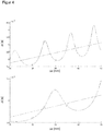
- FIG. 4 is a representation of the oscillation, similar FIG. 2 was obtained above and under comparable conditions for parameters not explicitly different from the formula for ⁇ .
- a fluid sound velocity of 1200 m / s and in the lower part of 2000 m / s is assumed, and the range for the axial distance ⁇ x on the X-axis has been changed to a relevant section around the axial distances ⁇ x of the path layout FIG. 3 limited.
- the transit time differences on the different measurement paths 18a-d are now determined and assigned to the respective axial distance ⁇ x of the measurement path 18a-d.
- the transit time difference could now be read at each point of the determined straight line and be closed over the associated axial distance ⁇ x to a path length in order to calculate the flow velocity.
- the straight line faithfully reproduces the conditions in the area of the actual support points, not only because of unavoidable measurement fluctuations, but also because of the non-uniform oscillation. Therefore, it is preferably read off in the area of the support points, in particular at a point which corresponds to the average of the realized axial distances ⁇ x.
- the highest quality of the mathematical adaptation is expected.
- additional groups corresponding to the measurement paths 18a-d can be formed in a different position with respect to the cross section, which then correspond in groups to the paths of a conventional multi-path counter.
- FIG. 5 again shows a representation of the oscillation or the function of the transit time difference as a function of the axial distance ⁇ x similarly FIG. 4 but for another example.
- seven instead of four measuring paths are provided whose axial distance ⁇ x varies by 2 mm in each case.
- the transit time differences determined on the measurement paths are assigned to the axial distance ⁇ x of the respective measurement path and are marked accordingly as X.
- FIG. 5 Here, not the previously presented simple model is used to determine the oscillation, but a much more realistic simulation with realistic waveforms and amplitude ratios and three structural sound modes, each with their own sound velocities and their own dispersion behavior.
- the resulting oscillation has a slightly different characteristic, but qualitatively differs only slightly and is still allowed to continue an evaluation, such as it was described above.
- a linear adjustment is possible, as a straight line in FIG. 5 is drawn and reconstructs the theoretical course of an undisturbed measurement only of the fluid sound without structure sound.
Priority Applications (4)
| Application Number | Priority Date | Filing Date | Title |
|---|---|---|---|
| EP18155305.8A EP3521774B1 (fr) | 2018-02-06 | 2018-02-06 | Dispositif de mesure d'écoulement à ultrasons et procédé de détermination de la vitesse d'écoulement |
| US16/193,088 US10718646B2 (en) | 2018-02-06 | 2018-11-16 | Ultrasound flow measurement apparatus and method for determining the flow rate |
| RU2018140562A RU2692824C1 (ru) | 2018-02-06 | 2018-11-16 | Ультразвуковое устройство измерения расхода и способ определения скорости потока |
| CN201811382081.0A CN110118583B (zh) | 2018-02-06 | 2018-11-20 | 超声波流量测量装置和用于确定流速的方法 |
Applications Claiming Priority (1)
| Application Number | Priority Date | Filing Date | Title |
|---|---|---|---|
| EP18155305.8A EP3521774B1 (fr) | 2018-02-06 | 2018-02-06 | Dispositif de mesure d'écoulement à ultrasons et procédé de détermination de la vitesse d'écoulement |
Publications (2)
| Publication Number | Publication Date |
|---|---|
| EP3521774A1 true EP3521774A1 (fr) | 2019-08-07 |
| EP3521774B1 EP3521774B1 (fr) | 2020-04-01 |
Family
ID=61167974
Family Applications (1)
| Application Number | Title | Priority Date | Filing Date |
|---|---|---|---|
| EP18155305.8A Active EP3521774B1 (fr) | 2018-02-06 | 2018-02-06 | Dispositif de mesure d'écoulement à ultrasons et procédé de détermination de la vitesse d'écoulement |
Country Status (4)
| Country | Link |
|---|---|
| US (1) | US10718646B2 (fr) |
| EP (1) | EP3521774B1 (fr) |
| CN (1) | CN110118583B (fr) |
| RU (1) | RU2692824C1 (fr) |
Families Citing this family (2)
| Publication number | Priority date | Publication date | Assignee | Title |
|---|---|---|---|---|
| US20210207984A1 (en) * | 2020-01-07 | 2021-07-08 | Trustees Of Tufts College | Systems and methods for operation of a sonic anemometer |
| CN113701835B (zh) * | 2021-08-30 | 2023-12-08 | 安徽理工大学 | 一种高精度自校正超声波煤层气抽采管网流量计 |
Citations (7)
| Publication number | Priority date | Publication date | Assignee | Title |
|---|---|---|---|---|
| US4467659A (en) | 1982-08-12 | 1984-08-28 | Joseph Baumoel | Transducer having metal housing and employing mode conversion |
| US20020053243A1 (en) * | 2000-09-15 | 2002-05-09 | Su Tyan Khak | Ultrasonic flow measuring method |
| EP1378272B1 (fr) | 2002-07-05 | 2006-04-05 | Equipamientos Y Materiales Deportivos, S.A. | Dispositif de rétention de filets et de cordes |
| US7658114B1 (en) * | 2008-11-17 | 2010-02-09 | General Electric Company | Ultrasonic flow meter |
| US20130174669A1 (en) * | 2012-01-10 | 2013-07-11 | General Electric Company | Method and appartus for determining flow velocity |
| DE102013101950A1 (de) * | 2012-05-03 | 2013-11-07 | Technische Universität Dresden | Anordnung und Verfahren zur Messung einer Strömungsgeschwindigkeit fluider Medien |
| DE202013105800U1 (de) | 2013-12-19 | 2015-03-20 | Sick Ag | Ultraschallmessvorrichtung zum Bestimmen der Strömungsgeschwindigkeit |
Family Cites Families (11)
| Publication number | Priority date | Publication date | Assignee | Title |
|---|---|---|---|---|
| DE10229925A1 (de) | 2002-07-04 | 2004-01-15 | Sick Engineering Gmbh | Vorrichtung zum Messen der Strömungsgeschwindigkeit und/oder des Durchflusses eines Fluids |
| DE102005047790A1 (de) * | 2005-10-05 | 2007-04-12 | Endress + Hauser Flowtec Ag | Vorrichtung zur Bestimmung oder Überwachung des Volumen- oder Massedurchflusses eines Mediums durch eine Rohrleitung |
| EP2386835B1 (fr) * | 2010-05-12 | 2015-11-25 | SICK Engineering GmbH | Mesure par ultrasons de la vitesse d'écoulement d'un fluide dans une conduite |
| PL3042155T3 (pl) * | 2013-09-05 | 2023-03-13 | Apator Miitors Aps | Przepływomierz ultradźwiękowy |
| DE102014115203B3 (de) * | 2014-10-20 | 2016-03-24 | Flexim Flexible Industriemesstechnik Gmbh | Verfahren und Anordnung zur Ultraschall-Clamp-on-Durchflussmessung und Schaltungsanordnung zur Steuerung einer Ultraschall-Clamp-on-Durchflussmessung |
| CN105737918B (zh) * | 2014-12-11 | 2019-05-10 | 通用电气公司 | 用来测量流体流量的超声方法和装置 |
| US9453749B1 (en) * | 2015-03-10 | 2016-09-27 | Honeywell International Inc. | Hybrid sensing ultrasonic flowmeter |
| JP6368916B2 (ja) * | 2015-04-16 | 2018-08-08 | パナソニックIpマネジメント株式会社 | 流量計測装置 |
| US10309813B2 (en) * | 2015-05-15 | 2019-06-04 | Reliance Worldwide Corporation | Method and system for fluid flow rate measurement |
| DE102015107752A1 (de) * | 2015-05-18 | 2016-11-24 | Endress + Hauser Flowtec Ag | Verfahren zur Ermittlung zumindest einer Rohrwandresonanzfrequenz sowie Clamp-On-Ultraschall-Durchflussmessgerät |
| DE102017004038B4 (de) * | 2017-02-03 | 2022-01-27 | Diehl Metering Gmbh | Ultraschallzähler und Verfahren zur Erfassung einer Durchflussgröße |
-
2018
- 2018-02-06 EP EP18155305.8A patent/EP3521774B1/fr active Active
- 2018-11-16 RU RU2018140562A patent/RU2692824C1/ru active
- 2018-11-16 US US16/193,088 patent/US10718646B2/en active Active
- 2018-11-20 CN CN201811382081.0A patent/CN110118583B/zh active Active
Patent Citations (7)
| Publication number | Priority date | Publication date | Assignee | Title |
|---|---|---|---|---|
| US4467659A (en) | 1982-08-12 | 1984-08-28 | Joseph Baumoel | Transducer having metal housing and employing mode conversion |
| US20020053243A1 (en) * | 2000-09-15 | 2002-05-09 | Su Tyan Khak | Ultrasonic flow measuring method |
| EP1378272B1 (fr) | 2002-07-05 | 2006-04-05 | Equipamientos Y Materiales Deportivos, S.A. | Dispositif de rétention de filets et de cordes |
| US7658114B1 (en) * | 2008-11-17 | 2010-02-09 | General Electric Company | Ultrasonic flow meter |
| US20130174669A1 (en) * | 2012-01-10 | 2013-07-11 | General Electric Company | Method and appartus for determining flow velocity |
| DE102013101950A1 (de) * | 2012-05-03 | 2013-11-07 | Technische Universität Dresden | Anordnung und Verfahren zur Messung einer Strömungsgeschwindigkeit fluider Medien |
| DE202013105800U1 (de) | 2013-12-19 | 2015-03-20 | Sick Ag | Ultraschallmessvorrichtung zum Bestimmen der Strömungsgeschwindigkeit |
Also Published As
| Publication number | Publication date |
|---|---|
| US20190242734A1 (en) | 2019-08-08 |
| CN110118583A (zh) | 2019-08-13 |
| EP3521774B1 (fr) | 2020-04-01 |
| US10718646B2 (en) | 2020-07-21 |
| CN110118583B (zh) | 2021-12-10 |
| RU2692824C1 (ru) | 2019-06-28 |
Similar Documents
| Publication | Publication Date | Title |
|---|---|---|
| EP3577427B1 (fr) | Compteur à ultrasons et procédé d'acquisition d'une grandeur de débit | |
| EP2732248B1 (fr) | Débitmètre à ultrasons | |
| EP1798532B1 (fr) | Débitmètre massique de Coriolis | |
| DE69719396T2 (de) | Ultraschallsensor und Verfahren zur Bestimmung der Geschwindigkeit einer Strömung | |
| EP2684010B1 (fr) | Procédé de mesure de débit par ultrasons et dispositif pour mettre en oeuvre ledit procédé | |
| DE69907913T2 (de) | Kreuzmessen von akustischen signalen eines durchflussmessers | |
| DE19620079C2 (de) | Massendurchflußmeßgerät | |
| WO2004046657A1 (fr) | Procede et dispositif permettant de determiner et/ou de surveiller un debit volumique et/ou massique | |
| EP3940346B1 (fr) | Débitmètre et procédé de mesure du débit d'un fluide | |
| EP3521774B1 (fr) | Dispositif de mesure d'écoulement à ultrasons et procédé de détermination de la vitesse d'écoulement | |
| CH692521A5 (de) | Massendurchflussmessgerät. | |
| EP1651931B1 (fr) | Debitmetre massique | |
| DE10314916A1 (de) | Vorrichtung zur Bestimmung und/oder Überwachung des Volumen- und/oder Massenstroms eines Mediums | |
| EP3470799B1 (fr) | Dispositif de mesure permettant de déterminer une propriété de fluide | |
| DE102018003311B4 (de) | Verfahren und Messeinrichtung zur Ermittlung einer Messinformation | |
| EP3769050A1 (fr) | Procédé pour la détermination non invasive du flux ou du débit dans un objet électriquement conducteur traversé par un médium gazeux ainsi que débitmètre acoustique pour l'exécution du procédé | |
| EP3855134B1 (fr) | Dispositif de mesure du débit d'écoulement d'un fluide | |
| DE102016125615A1 (de) | Messaufnehmer vom Vibrationstyp zum Messen der Dichte und/oder des Massedurchflusses eines Mediums | |
| EP3663728A1 (fr) | Dispositif de mesure permettant de déterminer une grandeur de fluide | |
| DE10062875B4 (de) | Durchflussmesser | |
| DE202020104105U1 (de) | Durchflussmessgerät zur Messung des Durchflusses eines Fluids | |
| WO2016142127A1 (fr) | Dispositif et appareil de terrain de la technique de mesure de processus | |
| DE102005034749A1 (de) | Coriolis-Massendurchflussmessgerät und Verfahren zur Herstellung eines Coriolis-Massendurchflussmessgeräts | |
| DE102004026322B3 (de) | Coriolis-Massendurchflußmeßgerät | |
| EP1628118A2 (fr) | Débitmètre massique Coriolis et methode pour fabriquer un débitmètre massique Coriolis |
Legal Events
| Date | Code | Title | Description |
|---|---|---|---|
| STAA | Information on the status of an ep patent application or granted ep patent |
Free format text: STATUS: EXAMINATION IS IN PROGRESS |
|
| PUAI | Public reference made under article 153(3) epc to a published international application that has entered the european phase |
Free format text: ORIGINAL CODE: 0009012 |
|
| 17P | Request for examination filed |
Effective date: 20181019 |
|
| AK | Designated contracting states |
Kind code of ref document: A1 Designated state(s): AL AT BE BG CH CY CZ DE DK EE ES FI FR GB GR HR HU IE IS IT LI LT LU LV MC MK MT NL NO PL PT RO RS SE SI SK SM TR |
|
| AX | Request for extension of the european patent |
Extension state: BA ME |
|
| GRAP | Despatch of communication of intention to grant a patent |
Free format text: ORIGINAL CODE: EPIDOSNIGR1 |
|
| STAA | Information on the status of an ep patent application or granted ep patent |
Free format text: STATUS: GRANT OF PATENT IS INTENDED |
|
| INTG | Intention to grant announced |
Effective date: 20191111 |
|
| GRAS | Grant fee paid |
Free format text: ORIGINAL CODE: EPIDOSNIGR3 |
|
| GRAA | (expected) grant |
Free format text: ORIGINAL CODE: 0009210 |
|
| STAA | Information on the status of an ep patent application or granted ep patent |
Free format text: STATUS: THE PATENT HAS BEEN GRANTED |
|
| AK | Designated contracting states |
Kind code of ref document: B1 Designated state(s): AL AT BE BG CH CY CZ DE DK EE ES FI FR GB GR HR HU IE IS IT LI LT LU LV MC MK MT NL NO PL PT RO RS SE SI SK SM TR |
|
| REG | Reference to a national code |
Ref country code: GB Ref legal event code: FG4D Free format text: NOT ENGLISH |
|
| REG | Reference to a national code |
Ref country code: AT Ref legal event code: REF Ref document number: 1251951 Country of ref document: AT Kind code of ref document: T Effective date: 20200415 Ref country code: CH Ref legal event code: EP |
|
| REG | Reference to a national code |
Ref country code: DE Ref legal event code: R096 Ref document number: 502018001055 Country of ref document: DE |
|
| REG | Reference to a national code |
Ref country code: IE Ref legal event code: FG4D Free format text: LANGUAGE OF EP DOCUMENT: GERMAN |
|
| PG25 | Lapsed in a contracting state [announced via postgrant information from national office to epo] |
Ref country code: BG Free format text: LAPSE BECAUSE OF FAILURE TO SUBMIT A TRANSLATION OF THE DESCRIPTION OR TO PAY THE FEE WITHIN THE PRESCRIBED TIME-LIMIT Effective date: 20200701 |
|
| REG | Reference to a national code |
Ref country code: NL Ref legal event code: MP Effective date: 20200401 |
|
| REG | Reference to a national code |
Ref country code: LT Ref legal event code: MG4D |
|
| PG25 | Lapsed in a contracting state [announced via postgrant information from national office to epo] |
Ref country code: GR Free format text: LAPSE BECAUSE OF FAILURE TO SUBMIT A TRANSLATION OF THE DESCRIPTION OR TO PAY THE FEE WITHIN THE PRESCRIBED TIME-LIMIT Effective date: 20200702 Ref country code: NO Free format text: LAPSE BECAUSE OF FAILURE TO SUBMIT A TRANSLATION OF THE DESCRIPTION OR TO PAY THE FEE WITHIN THE PRESCRIBED TIME-LIMIT Effective date: 20200701 Ref country code: SE Free format text: LAPSE BECAUSE OF FAILURE TO SUBMIT A TRANSLATION OF THE DESCRIPTION OR TO PAY THE FEE WITHIN THE PRESCRIBED TIME-LIMIT Effective date: 20200401 Ref country code: PT Free format text: LAPSE BECAUSE OF FAILURE TO SUBMIT A TRANSLATION OF THE DESCRIPTION OR TO PAY THE FEE WITHIN THE PRESCRIBED TIME-LIMIT Effective date: 20200817 Ref country code: FI Free format text: LAPSE BECAUSE OF FAILURE TO SUBMIT A TRANSLATION OF THE DESCRIPTION OR TO PAY THE FEE WITHIN THE PRESCRIBED TIME-LIMIT Effective date: 20200401 Ref country code: NL Free format text: LAPSE BECAUSE OF FAILURE TO SUBMIT A TRANSLATION OF THE DESCRIPTION OR TO PAY THE FEE WITHIN THE PRESCRIBED TIME-LIMIT Effective date: 20200401 Ref country code: LT Free format text: LAPSE BECAUSE OF FAILURE TO SUBMIT A TRANSLATION OF THE DESCRIPTION OR TO PAY THE FEE WITHIN THE PRESCRIBED TIME-LIMIT Effective date: 20200401 Ref country code: CZ Free format text: LAPSE BECAUSE OF FAILURE TO SUBMIT A TRANSLATION OF THE DESCRIPTION OR TO PAY THE FEE WITHIN THE PRESCRIBED TIME-LIMIT Effective date: 20200401 Ref country code: IS Free format text: LAPSE BECAUSE OF FAILURE TO SUBMIT A TRANSLATION OF THE DESCRIPTION OR TO PAY THE FEE WITHIN THE PRESCRIBED TIME-LIMIT Effective date: 20200801 |
|
| PG25 | Lapsed in a contracting state [announced via postgrant information from national office to epo] |
Ref country code: HR Free format text: LAPSE BECAUSE OF FAILURE TO SUBMIT A TRANSLATION OF THE DESCRIPTION OR TO PAY THE FEE WITHIN THE PRESCRIBED TIME-LIMIT Effective date: 20200401 Ref country code: RS Free format text: LAPSE BECAUSE OF FAILURE TO SUBMIT A TRANSLATION OF THE DESCRIPTION OR TO PAY THE FEE WITHIN THE PRESCRIBED TIME-LIMIT Effective date: 20200401 Ref country code: LV Free format text: LAPSE BECAUSE OF FAILURE TO SUBMIT A TRANSLATION OF THE DESCRIPTION OR TO PAY THE FEE WITHIN THE PRESCRIBED TIME-LIMIT Effective date: 20200401 |
|
| PG25 | Lapsed in a contracting state [announced via postgrant information from national office to epo] |
Ref country code: AL Free format text: LAPSE BECAUSE OF FAILURE TO SUBMIT A TRANSLATION OF THE DESCRIPTION OR TO PAY THE FEE WITHIN THE PRESCRIBED TIME-LIMIT Effective date: 20200401 |
|
| REG | Reference to a national code |
Ref country code: DE Ref legal event code: R097 Ref document number: 502018001055 Country of ref document: DE |
|
| PG25 | Lapsed in a contracting state [announced via postgrant information from national office to epo] |
Ref country code: RO Free format text: LAPSE BECAUSE OF FAILURE TO SUBMIT A TRANSLATION OF THE DESCRIPTION OR TO PAY THE FEE WITHIN THE PRESCRIBED TIME-LIMIT Effective date: 20200401 Ref country code: DK Free format text: LAPSE BECAUSE OF FAILURE TO SUBMIT A TRANSLATION OF THE DESCRIPTION OR TO PAY THE FEE WITHIN THE PRESCRIBED TIME-LIMIT Effective date: 20200401 Ref country code: SM Free format text: LAPSE BECAUSE OF FAILURE TO SUBMIT A TRANSLATION OF THE DESCRIPTION OR TO PAY THE FEE WITHIN THE PRESCRIBED TIME-LIMIT Effective date: 20200401 Ref country code: EE Free format text: LAPSE BECAUSE OF FAILURE TO SUBMIT A TRANSLATION OF THE DESCRIPTION OR TO PAY THE FEE WITHIN THE PRESCRIBED TIME-LIMIT Effective date: 20200401 Ref country code: ES Free format text: LAPSE BECAUSE OF FAILURE TO SUBMIT A TRANSLATION OF THE DESCRIPTION OR TO PAY THE FEE WITHIN THE PRESCRIBED TIME-LIMIT Effective date: 20200401 |
|
| PLBE | No opposition filed within time limit |
Free format text: ORIGINAL CODE: 0009261 |
|
| STAA | Information on the status of an ep patent application or granted ep patent |
Free format text: STATUS: NO OPPOSITION FILED WITHIN TIME LIMIT |
|
| PG25 | Lapsed in a contracting state [announced via postgrant information from national office to epo] |
Ref country code: SK Free format text: LAPSE BECAUSE OF FAILURE TO SUBMIT A TRANSLATION OF THE DESCRIPTION OR TO PAY THE FEE WITHIN THE PRESCRIBED TIME-LIMIT Effective date: 20200401 Ref country code: PL Free format text: LAPSE BECAUSE OF FAILURE TO SUBMIT A TRANSLATION OF THE DESCRIPTION OR TO PAY THE FEE WITHIN THE PRESCRIBED TIME-LIMIT Effective date: 20200401 |
|
| 26N | No opposition filed |
Effective date: 20210112 |
|
| PG25 | Lapsed in a contracting state [announced via postgrant information from national office to epo] |
Ref country code: MC Free format text: LAPSE BECAUSE OF FAILURE TO SUBMIT A TRANSLATION OF THE DESCRIPTION OR TO PAY THE FEE WITHIN THE PRESCRIBED TIME-LIMIT Effective date: 20200401 |
|
| REG | Reference to a national code |
Ref country code: BE Ref legal event code: MM Effective date: 20210228 |
|
| PG25 | Lapsed in a contracting state [announced via postgrant information from national office to epo] |
Ref country code: CH Free format text: LAPSE BECAUSE OF NON-PAYMENT OF DUE FEES Effective date: 20210228 Ref country code: LU Free format text: LAPSE BECAUSE OF NON-PAYMENT OF DUE FEES Effective date: 20210206 Ref country code: LI Free format text: LAPSE BECAUSE OF NON-PAYMENT OF DUE FEES Effective date: 20210228 |
|
| PG25 | Lapsed in a contracting state [announced via postgrant information from national office to epo] |
Ref country code: IE Free format text: LAPSE BECAUSE OF NON-PAYMENT OF DUE FEES Effective date: 20210206 |
|
| PG25 | Lapsed in a contracting state [announced via postgrant information from national office to epo] |
Ref country code: BE Free format text: LAPSE BECAUSE OF NON-PAYMENT OF DUE FEES Effective date: 20210228 |
|
| PGFP | Annual fee paid to national office [announced via postgrant information from national office to epo] |
Ref country code: FR Payment date: 20230220 Year of fee payment: 6 |
|
| PGFP | Annual fee paid to national office [announced via postgrant information from national office to epo] |
Ref country code: IT Payment date: 20230228 Year of fee payment: 6 |
|
| PG25 | Lapsed in a contracting state [announced via postgrant information from national office to epo] |
Ref country code: CY Free format text: LAPSE BECAUSE OF FAILURE TO SUBMIT A TRANSLATION OF THE DESCRIPTION OR TO PAY THE FEE WITHIN THE PRESCRIBED TIME-LIMIT Effective date: 20200401 |
|
| PG25 | Lapsed in a contracting state [announced via postgrant information from national office to epo] |
Ref country code: HU Free format text: LAPSE BECAUSE OF FAILURE TO SUBMIT A TRANSLATION OF THE DESCRIPTION OR TO PAY THE FEE WITHIN THE PRESCRIBED TIME-LIMIT; INVALID AB INITIO Effective date: 20180206 |
|
| PG25 | Lapsed in a contracting state [announced via postgrant information from national office to epo] |
Ref country code: SI Free format text: LAPSE BECAUSE OF FAILURE TO SUBMIT A TRANSLATION OF THE DESCRIPTION OR TO PAY THE FEE WITHIN THE PRESCRIBED TIME-LIMIT Effective date: 20200401 |
|
| REG | Reference to a national code |
Ref country code: AT Ref legal event code: MM01 Ref document number: 1251951 Country of ref document: AT Kind code of ref document: T Effective date: 20230206 |
|
| PG25 | Lapsed in a contracting state [announced via postgrant information from national office to epo] |
Ref country code: AT Free format text: LAPSE BECAUSE OF NON-PAYMENT OF DUE FEES Effective date: 20230206 |
|
| PG25 | Lapsed in a contracting state [announced via postgrant information from national office to epo] |
Ref country code: MK Free format text: LAPSE BECAUSE OF FAILURE TO SUBMIT A TRANSLATION OF THE DESCRIPTION OR TO PAY THE FEE WITHIN THE PRESCRIBED TIME-LIMIT Effective date: 20200401 Ref country code: AT Free format text: LAPSE BECAUSE OF NON-PAYMENT OF DUE FEES Effective date: 20230206 |
|
| PGFP | Annual fee paid to national office [announced via postgrant information from national office to epo] |
Ref country code: DE Payment date: 20240216 Year of fee payment: 7 Ref country code: GB Payment date: 20240222 Year of fee payment: 7 |