EP3521588A2 - Rotary axial valve - Google Patents
Rotary axial valve Download PDFInfo
- Publication number
- EP3521588A2 EP3521588A2 EP19154815.5A EP19154815A EP3521588A2 EP 3521588 A2 EP3521588 A2 EP 3521588A2 EP 19154815 A EP19154815 A EP 19154815A EP 3521588 A2 EP3521588 A2 EP 3521588A2
- Authority
- EP
- European Patent Office
- Prior art keywords
- outlet
- valve structure
- face
- exhaust gas
- housing
- Prior art date
- Legal status (The legal status is an assumption and is not a legal conclusion. Google has not performed a legal analysis and makes no representation as to the accuracy of the status listed.)
- Granted
Links
- 238000011144 upstream manufacturing Methods 0.000 claims abstract description 71
- 238000002485 combustion reaction Methods 0.000 claims description 25
- 238000000034 method Methods 0.000 claims description 6
- 239000000446 fuel Substances 0.000 claims description 3
- 239000003570 air Substances 0.000 description 11
- 239000012530 fluid Substances 0.000 description 7
- 238000007789 sealing Methods 0.000 description 3
- 239000003054 catalyst Substances 0.000 description 2
- 230000001276 controlling effect Effects 0.000 description 2
- 230000036316 preload Effects 0.000 description 2
- 239000000126 substance Substances 0.000 description 2
- 239000012080 ambient air Substances 0.000 description 1
- 230000000712 assembly Effects 0.000 description 1
- 238000000429 assembly Methods 0.000 description 1
- 230000001105 regulatory effect Effects 0.000 description 1
- 239000007787 solid Substances 0.000 description 1
Images


Classifications
-
- F—MECHANICAL ENGINEERING; LIGHTING; HEATING; WEAPONS; BLASTING
- F02—COMBUSTION ENGINES; HOT-GAS OR COMBUSTION-PRODUCT ENGINE PLANTS
- F02B—INTERNAL-COMBUSTION PISTON ENGINES; COMBUSTION ENGINES IN GENERAL
- F02B37/00—Engines characterised by provision of pumps driven at least for part of the time by exhaust
- F02B37/12—Control of the pumps
- F02B37/18—Control of the pumps by bypassing exhaust from the inlet to the outlet of turbine or to the atmosphere
- F02B37/183—Arrangements of bypass valves or actuators therefor
-
- F—MECHANICAL ENGINEERING; LIGHTING; HEATING; WEAPONS; BLASTING
- F01—MACHINES OR ENGINES IN GENERAL; ENGINE PLANTS IN GENERAL; STEAM ENGINES
- F01D—NON-POSITIVE DISPLACEMENT MACHINES OR ENGINES, e.g. STEAM TURBINES
- F01D17/00—Regulating or controlling by varying flow
- F01D17/10—Final actuators
-
- F—MECHANICAL ENGINEERING; LIGHTING; HEATING; WEAPONS; BLASTING
- F02—COMBUSTION ENGINES; HOT-GAS OR COMBUSTION-PRODUCT ENGINE PLANTS
- F02B—INTERNAL-COMBUSTION PISTON ENGINES; COMBUSTION ENGINES IN GENERAL
- F02B37/00—Engines characterised by provision of pumps driven at least for part of the time by exhaust
- F02B37/12—Control of the pumps
- F02B37/22—Control of the pumps by varying cross-section of exhaust passages or air passages, e.g. by throttling turbine inlets or outlets or by varying effective number of guide conduits
-
- F—MECHANICAL ENGINEERING; LIGHTING; HEATING; WEAPONS; BLASTING
- F02—COMBUSTION ENGINES; HOT-GAS OR COMBUSTION-PRODUCT ENGINE PLANTS
- F02C—GAS-TURBINE PLANTS; AIR INTAKES FOR JET-PROPULSION PLANTS; CONTROLLING FUEL SUPPLY IN AIR-BREATHING JET-PROPULSION PLANTS
- F02C6/00—Plural gas-turbine plants; Combinations of gas-turbine plants with other apparatus; Adaptations of gas- turbine plants for special use
- F02C6/04—Gas-turbine plants providing heated or pressurised working fluid for other apparatus, e.g. without mechanical power output
- F02C6/10—Gas-turbine plants providing heated or pressurised working fluid for other apparatus, e.g. without mechanical power output supplying working fluid to a user, e.g. a chemical process, which returns working fluid to a turbine of the plant
- F02C6/12—Turbochargers, i.e. plants for augmenting mechanical power output of internal-combustion piston engines by increase of charge pressure
-
- F—MECHANICAL ENGINEERING; LIGHTING; HEATING; WEAPONS; BLASTING
- F02—COMBUSTION ENGINES; HOT-GAS OR COMBUSTION-PRODUCT ENGINE PLANTS
- F02D—CONTROLLING COMBUSTION ENGINES
- F02D41/00—Electrical control of supply of combustible mixture or its constituents
- F02D41/0025—Controlling engines characterised by use of non-liquid fuels, pluralities of fuels, or non-fuel substances added to the combustible mixtures
- F02D41/0047—Controlling exhaust gas recirculation [EGR]
- F02D41/0077—Control of the EGR valve or actuator, e.g. duty cycle, closed loop control of position
-
- F—MECHANICAL ENGINEERING; LIGHTING; HEATING; WEAPONS; BLASTING
- F02—COMBUSTION ENGINES; HOT-GAS OR COMBUSTION-PRODUCT ENGINE PLANTS
- F02M—SUPPLYING COMBUSTION ENGINES IN GENERAL WITH COMBUSTIBLE MIXTURES OR CONSTITUENTS THEREOF
- F02M26/00—Engine-pertinent apparatus for adding exhaust gases to combustion-air, main fuel or fuel-air mixture, e.g. by exhaust gas recirculation [EGR] systems
- F02M26/02—EGR systems specially adapted for supercharged engines
- F02M26/04—EGR systems specially adapted for supercharged engines with a single turbocharger
- F02M26/05—High pressure loops, i.e. wherein recirculated exhaust gas is taken out from the exhaust system upstream of the turbine and reintroduced into the intake system downstream of the compressor
-
- F—MECHANICAL ENGINEERING; LIGHTING; HEATING; WEAPONS; BLASTING
- F02—COMBUSTION ENGINES; HOT-GAS OR COMBUSTION-PRODUCT ENGINE PLANTS
- F02M—SUPPLYING COMBUSTION ENGINES IN GENERAL WITH COMBUSTIBLE MIXTURES OR CONSTITUENTS THEREOF
- F02M26/00—Engine-pertinent apparatus for adding exhaust gases to combustion-air, main fuel or fuel-air mixture, e.g. by exhaust gas recirculation [EGR] systems
- F02M26/13—Arrangement or layout of EGR passages, e.g. in relation to specific engine parts or for incorporation of accessories
- F02M26/42—Arrangement or layout of EGR passages, e.g. in relation to specific engine parts or for incorporation of accessories having two or more EGR passages; EGR systems specially adapted for engines having two or more cylinders
- F02M26/43—Arrangement or layout of EGR passages, e.g. in relation to specific engine parts or for incorporation of accessories having two or more EGR passages; EGR systems specially adapted for engines having two or more cylinders in which exhaust from only one cylinder or only a group of cylinders is directed to the intake of the engine
-
- F—MECHANICAL ENGINEERING; LIGHTING; HEATING; WEAPONS; BLASTING
- F02—COMBUSTION ENGINES; HOT-GAS OR COMBUSTION-PRODUCT ENGINE PLANTS
- F02M—SUPPLYING COMBUSTION ENGINES IN GENERAL WITH COMBUSTIBLE MIXTURES OR CONSTITUENTS THEREOF
- F02M26/00—Engine-pertinent apparatus for adding exhaust gases to combustion-air, main fuel or fuel-air mixture, e.g. by exhaust gas recirculation [EGR] systems
- F02M26/51—EGR valves combined with other devices, e.g. with intake valves or compressors
-
- F—MECHANICAL ENGINEERING; LIGHTING; HEATING; WEAPONS; BLASTING
- F02—COMBUSTION ENGINES; HOT-GAS OR COMBUSTION-PRODUCT ENGINE PLANTS
- F02M—SUPPLYING COMBUSTION ENGINES IN GENERAL WITH COMBUSTIBLE MIXTURES OR CONSTITUENTS THEREOF
- F02M26/00—Engine-pertinent apparatus for adding exhaust gases to combustion-air, main fuel or fuel-air mixture, e.g. by exhaust gas recirculation [EGR] systems
- F02M26/52—Systems for actuating EGR valves
-
- F—MECHANICAL ENGINEERING; LIGHTING; HEATING; WEAPONS; BLASTING
- F02—COMBUSTION ENGINES; HOT-GAS OR COMBUSTION-PRODUCT ENGINE PLANTS
- F02M—SUPPLYING COMBUSTION ENGINES IN GENERAL WITH COMBUSTIBLE MIXTURES OR CONSTITUENTS THEREOF
- F02M26/00—Engine-pertinent apparatus for adding exhaust gases to combustion-air, main fuel or fuel-air mixture, e.g. by exhaust gas recirculation [EGR] systems
- F02M26/65—Constructional details of EGR valves
- F02M26/70—Flap valves; Rotary valves; Sliding valves; Resilient valves
-
- F—MECHANICAL ENGINEERING; LIGHTING; HEATING; WEAPONS; BLASTING
- F02—COMBUSTION ENGINES; HOT-GAS OR COMBUSTION-PRODUCT ENGINE PLANTS
- F02M—SUPPLYING COMBUSTION ENGINES IN GENERAL WITH COMBUSTIBLE MIXTURES OR CONSTITUENTS THEREOF
- F02M26/00—Engine-pertinent apparatus for adding exhaust gases to combustion-air, main fuel or fuel-air mixture, e.g. by exhaust gas recirculation [EGR] systems
- F02M26/65—Constructional details of EGR valves
- F02M26/71—Multi-way valves
-
- F—MECHANICAL ENGINEERING; LIGHTING; HEATING; WEAPONS; BLASTING
- F02—COMBUSTION ENGINES; HOT-GAS OR COMBUSTION-PRODUCT ENGINE PLANTS
- F02M—SUPPLYING COMBUSTION ENGINES IN GENERAL WITH COMBUSTIBLE MIXTURES OR CONSTITUENTS THEREOF
- F02M26/00—Engine-pertinent apparatus for adding exhaust gases to combustion-air, main fuel or fuel-air mixture, e.g. by exhaust gas recirculation [EGR] systems
- F02M26/65—Constructional details of EGR valves
- F02M26/72—Housings
-
- F—MECHANICAL ENGINEERING; LIGHTING; HEATING; WEAPONS; BLASTING
- F16—ENGINEERING ELEMENTS AND UNITS; GENERAL MEASURES FOR PRODUCING AND MAINTAINING EFFECTIVE FUNCTIONING OF MACHINES OR INSTALLATIONS; THERMAL INSULATION IN GENERAL
- F16K—VALVES; TAPS; COCKS; ACTUATING-FLOATS; DEVICES FOR VENTING OR AERATING
- F16K11/00—Multiple-way valves, e.g. mixing valves; Pipe fittings incorporating such valves
- F16K11/02—Multiple-way valves, e.g. mixing valves; Pipe fittings incorporating such valves with all movable sealing faces moving as one unit
- F16K11/04—Multiple-way valves, e.g. mixing valves; Pipe fittings incorporating such valves with all movable sealing faces moving as one unit comprising only lift valves
- F16K11/052—Multiple-way valves, e.g. mixing valves; Pipe fittings incorporating such valves with all movable sealing faces moving as one unit comprising only lift valves with pivoted closure members, e.g. butterfly valves
- F16K11/0525—Multiple-way valves, e.g. mixing valves; Pipe fittings incorporating such valves with all movable sealing faces moving as one unit comprising only lift valves with pivoted closure members, e.g. butterfly valves the closure members being pivoted around an essentially central axis
-
- F—MECHANICAL ENGINEERING; LIGHTING; HEATING; WEAPONS; BLASTING
- F16—ENGINEERING ELEMENTS AND UNITS; GENERAL MEASURES FOR PRODUCING AND MAINTAINING EFFECTIVE FUNCTIONING OF MACHINES OR INSTALLATIONS; THERMAL INSULATION IN GENERAL
- F16K—VALVES; TAPS; COCKS; ACTUATING-FLOATS; DEVICES FOR VENTING OR AERATING
- F16K11/00—Multiple-way valves, e.g. mixing valves; Pipe fittings incorporating such valves
- F16K11/02—Multiple-way valves, e.g. mixing valves; Pipe fittings incorporating such valves with all movable sealing faces moving as one unit
- F16K11/08—Multiple-way valves, e.g. mixing valves; Pipe fittings incorporating such valves with all movable sealing faces moving as one unit comprising only taps or cocks
- F16K11/085—Multiple-way valves, e.g. mixing valves; Pipe fittings incorporating such valves with all movable sealing faces moving as one unit comprising only taps or cocks with cylindrical plug
-
- F—MECHANICAL ENGINEERING; LIGHTING; HEATING; WEAPONS; BLASTING
- F16—ENGINEERING ELEMENTS AND UNITS; GENERAL MEASURES FOR PRODUCING AND MAINTAINING EFFECTIVE FUNCTIONING OF MACHINES OR INSTALLATIONS; THERMAL INSULATION IN GENERAL
- F16K—VALVES; TAPS; COCKS; ACTUATING-FLOATS; DEVICES FOR VENTING OR AERATING
- F16K3/00—Gate valves or sliding valves, i.e. cut-off apparatus with closing members having a sliding movement along the seat for opening and closing
- F16K3/02—Gate valves or sliding valves, i.e. cut-off apparatus with closing members having a sliding movement along the seat for opening and closing with flat sealing faces; Packings therefor
- F16K3/04—Gate valves or sliding valves, i.e. cut-off apparatus with closing members having a sliding movement along the seat for opening and closing with flat sealing faces; Packings therefor with pivoted closure members
-
- F—MECHANICAL ENGINEERING; LIGHTING; HEATING; WEAPONS; BLASTING
- F01—MACHINES OR ENGINES IN GENERAL; ENGINE PLANTS IN GENERAL; STEAM ENGINES
- F01N—GAS-FLOW SILENCERS OR EXHAUST APPARATUS FOR MACHINES OR ENGINES IN GENERAL; GAS-FLOW SILENCERS OR EXHAUST APPARATUS FOR INTERNAL COMBUSTION ENGINES
- F01N3/00—Exhaust or silencing apparatus having means for purifying, rendering innocuous, or otherwise treating exhaust
- F01N3/08—Exhaust or silencing apparatus having means for purifying, rendering innocuous, or otherwise treating exhaust for rendering innocuous
- F01N3/10—Exhaust or silencing apparatus having means for purifying, rendering innocuous, or otherwise treating exhaust for rendering innocuous by thermal or catalytic conversion of noxious components of exhaust
- F01N3/101—Three-way catalysts
-
- F—MECHANICAL ENGINEERING; LIGHTING; HEATING; WEAPONS; BLASTING
- F02—COMBUSTION ENGINES; HOT-GAS OR COMBUSTION-PRODUCT ENGINE PLANTS
- F02M—SUPPLYING COMBUSTION ENGINES IN GENERAL WITH COMBUSTIBLE MIXTURES OR CONSTITUENTS THEREOF
- F02M26/00—Engine-pertinent apparatus for adding exhaust gases to combustion-air, main fuel or fuel-air mixture, e.g. by exhaust gas recirculation [EGR] systems
- F02M26/13—Arrangement or layout of EGR passages, e.g. in relation to specific engine parts or for incorporation of accessories
- F02M26/22—Arrangement or layout of EGR passages, e.g. in relation to specific engine parts or for incorporation of accessories with coolers in the recirculation passage
-
- Y—GENERAL TAGGING OF NEW TECHNOLOGICAL DEVELOPMENTS; GENERAL TAGGING OF CROSS-SECTIONAL TECHNOLOGIES SPANNING OVER SEVERAL SECTIONS OF THE IPC; TECHNICAL SUBJECTS COVERED BY FORMER USPC CROSS-REFERENCE ART COLLECTIONS [XRACs] AND DIGESTS
- Y02—TECHNOLOGIES OR APPLICATIONS FOR MITIGATION OR ADAPTATION AGAINST CLIMATE CHANGE
- Y02T—CLIMATE CHANGE MITIGATION TECHNOLOGIES RELATED TO TRANSPORTATION
- Y02T10/00—Road transport of goods or passengers
- Y02T10/10—Internal combustion engine [ICE] based vehicles
- Y02T10/12—Improving ICE efficiencies
Definitions
- the present disclosure generally relates to a valve and, more particularly, relates to a rotary axial valve for a turbocharger system.
- turbochargers include a turbine wheel and a compressor wheel mounted on a common shaft and carried within isolated turbine and compressor housings, respectively.
- the turbine wheel may be driven in rotation by exhaust gas output by the engine. This, in turn, rotates the compressor wheel for compressing air that is fed to the combustion chambers of the engine. Accordingly, the turbocharger may provide a performance boost and increased efficiency to the engine.
- Exhaust gas flow through the turbocharger system may change depending on the operating conditions of the engine. For example, in lower-load conditions, exhaust gas mass flow may be relatively low. In contrast, in higher-load conditions, exhaust gas mass flow may be relatively high. Also, exhaust gas flow may be different during engine startup as compared to when the engine has been running for some time. Other operating conditions may affect exhaust gas flow as well.
- turbocharger system that regulates the flow of exhaust gas in a variety of operating conditions.
- valve assembly for a turbocharger system that effectively controls the flow of exhaust gas, wherein input forces for actuating the valve are relatively low, and wherein exhaust gas leakage through the valve assembly is relatively low.
- a turbocharger system in one embodiment, includes a housing with an inlet, a first outlet, and a second outlet.
- the inlet is configured for receiving flow of an exhaust gas from an engine.
- the system also includes a turbine wheel of a turbocharger that is configured to be driven in rotation by a first flow of the exhaust gas. The first flow is received from the first outlet of the housing.
- the turbocharger system includes a second exhaust system that is configured to receive a second flow of the exhaust gas. The second flow is received from the second outlet of the housing.
- the turbocharger system further includes a valve structure that is disposed within the housing. The valve structure is configured to rotate about an axis of rotation between a first position and a second position.
- the valve structure defines a flow passage with an upstream end, a downstream end, and a nonlinear axis that extends between the upstream end and the downstream end.
- the upstream end is directed substantially along the axis of rotation and configured to receive the exhaust gas from the inlet.
- the downstream end is configured to deliver the exhaust gas to one of the first outlet and the second outlet.
- the valve structure, in the first position is configured to direct the exhaust gas along the first flow from the upstream end, through the flow passage, to the downstream end and the first outlet for driving the turbine wheel.
- the valve structure, in the first position is configured to substantially close off the second outlet.
- the valve structure in the second position, is configured to direct the exhaust gas along the second flow from the upstream end, through the flow passage, to the downstream end and the second outlet for delivery to the second exhaust system.
- the valve structure, in the second position, is configured to substantially close off the first outlet.
- a method of operating a turbocharger system includes generating, with an engine, an exhaust gas flow directed toward an inlet of a housing.
- the housing has a first outlet and a second outlet.
- the method also includes selectively rotating, with a control system, a valve structure about an axis of rotation within the housing between a first position and a second position to regulate the exhaust gas flow through the housing.
- the valve structure defines a flow passage with an upstream end, a downstream end, and a nonlinear axis that extends between the upstream end and the downstream end.
- the upstream end is directed substantially along the axis of rotation and is configured to receive the exhaust gas from the inlet.
- the downstream end is configured to deliver the exhaust gas to one of the first outlet and the second outlet.
- the valve structure in the first position, directs the exhaust gas flow from the upstream end, through the flow passage, to the downstream end and the first outlet for driving a turbine wheel of a turbocharger.
- the valve structure substantially closes off the second outlet when in the first position.
- the valve structure, in the second position directs the exhaust gas flow from the upstream end, through the flow passage, to the downstream end and the second outlet for delivery to a second exhaust system.
- the valve structure substantially closes off the first outlet when in the second position.
- a turbocharger system in a further embodiment, includes an engine configured to output a flow of exhaust gas.
- the turbocharger system also includes a turbocharger with a turbine wheel and an exhaust gas recirculation (EGR) system.
- EGR exhaust gas recirculation
- the turbocharger system includes a valve assembly having a valve housing defining an inlet, a first outlet, and a second outlet.
- the valve assembly also includes a bushing that is fixed to the valve housing. The bushing has a first portion that is received within the valve housing and a second portion that projects from an inner surface of the valve housing.
- the valve assembly also includes a valve structure that is disposed within the housing.
- the valve structure includes a body and a shaft that extends from a downstream face of the body.
- the shaft is received within and supported for rotation by the bushing between a first position and a second position.
- the body includes an upstream face that is directed along the axis of rotation and a downstream face that faces opposite the upstream face.
- the body includes a radial face that is directed radially with respect to the axis of rotation and that extends between the upstream face and the downstream face.
- the downstream face faces toward an inner surface of the valve housing.
- the body includes a flow passage with an upstream end in the upstream face and a downstream end in the radial face. The upstream end is configured to receive the exhaust gas from the inlet.
- the downstream end is configured to deliver the exhaust gas to one of the first outlet and the second outlet, and wherein the downstream face is configured to compress against the bushing and the inner surface of the valve housing under a load from the exhaust gas on the body.
- the body in the first position, is configured to direct the exhaust gas from the upstream end, through the flow passage, to the downstream end and the first outlet for driving the turbine wheel.
- a second control surface of the radial face, in the first position is configured to substantially close off the second outlet.
- the body, in the second position is configured to direct the exhaust gas from the upstream end, through the flow passage, to the downstream end and the second outlet for delivery to the (EGR) system.
- a first control surface of the radial face, in the second position is configured to substantially close off the first outlet.
- the downstream end is disposed circumferentially between the first control surface and the second control surface on the radial face.
- example embodiments disclosed herein include a turbocharger system with a valve assembly that is configured to provide improved and selective control of an engine's exhaust gas flow between two or more systems or devices.
- the valve assembly may have at least two positions. In one position, the valve assembly may direct the exhaust gas to a turbine section of a turbocharger, and in another position, the valve assembly may direct the flow to a second exhaust system (e.g., an aftertreatment system (e.g., an exhaust gas recirculation (EGR) system, etc.), a wastegate system, etc.).
- EGR exhaust gas recirculation
- the valve assembly may include a valve housing that defines an inlet and at least two outlets.
- the valve assembly may also include a valve structure that is supported for movement within the valve housing to regulate exhaust gas flow through the valve assembly (i.e., from the inlet to one of the outlets).
- the valve structure may include a flow passage with an upstream end that is directed axially and a downstream end that is directed substantially in a radial direction.
- the valve structure may rotate to change the circumferential position (i.e., the rotational angle) of the downstream end. As such, the valve structure may rotate to change the exhaust gas flow between the first outlet and the second outlet of the valve housing.
- the valve structure may have a first position in which the valve structure directs flow from the inlet of the valve housing to the first outlet while substantially sealing off the second outlet of the valve housing. In contrast, in the second position, the valve structure may direct flow from the inlet to the second outlet while substantially sealing off the first outlet of the valve housing. In other words, opening one outlet in the valve assembly closes off the other outlet and vice versa.
- valve assembly may be configured such that the valve structure moves under relatively low input loads.
- loads on the valve structure from the exhaust gas may serve to "preload” the valve assembly. In other words, these loads may push the valve structure against opposing surfaces to create a seal that limits exhaust gas leakage from the valve assembly.
- the valve structure may be supported for rotation via a bushing that is fixed to the valve housing and that projects from an inner surface of the valve housing.
- the projecting portion of the bushing may be received within a body of the valve structure.
- the axial load from the exhaust gas may serve to strengthen a fluid seal between the valve structure and the bushing to reduce leakage.
- a clearance path (defined between the body of the valve structure and the valve housing as well as between the body and the bushing) may be substantially nonlinear to reduce exhaust gas leakage from the valve assembly.
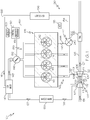
- FIG. 1 is a schematic view of a turbocharger system 104 according to example embodiments of the present disclosure.
- the turbocharger system 104 may be included in a vehicle of a variety of types (cars, trucks, vans, or other vehicles) without departing from the scope of the present disclosure.
- the turbocharger system 104 may include a turbocharger 100 and an engine 125.
- the engine 125 may be one of a variety of types, such as a diesel engine.
- the engine 125 may include a first combustion chamber 112, a second combustion chamber 114, a third combustion chamber 116, and a fourth combustion chamber 118.
- Each combustion chamber 112, 114, 116, 118 may produce exhaust gas that flows through respective branches of an exhaust manifold 123, which converges at an exhaust inlet pipe 119 for delivery to the turbocharger 100.
- the turbocharger 100 may include a turbocharger housing 101 and a rotor 102.
- the rotor 102 is configured to rotate within the turbocharger housing 101 about an axis of rotation 103.
- the rotor 102 may be supported for rotation via one or more bearings (not shown).
- the rotor 102 may be rotationally supported by thrust bearings and a plurality of journal bearings. Alternatively, other bearings may be included.
- the turbocharger housing 101 may include a turbine housing 105, a compressor housing 107, and a bearing housing 109.
- the bearing housing 109 may be disposed between the turbine and compressor housings 105, 107.
- the bearing housing 109 may contain the bearings of the rotor 102.
- the rotor 102 may include at least one turbine wheel 111, a compressor wheel 113, and a shaft 115.
- the turbine wheel(s) 111 is/are located substantially within the turbine housing 105.
- the compressor wheel 113 is located substantially within the compressor housing 107.
- the shaft 115 extends along the axis of rotation 103, through the bearing housing 109, to connect the turbine wheel(s) 111 to the compressor wheel 113. Accordingly, the turbine wheel(s) 111 and the compressor wheel 113 rotate together about the axis 103.
- the compressor housing 107 and compressor wheel 113 cooperate to define a compressor (i.e., compressor section, compressor stage).
- the compressor wheel 113 is configured to compress axially received input air (e.g., ambient air 131, or already-pressurized air from a previous-stage in a multi-stage compressor) into a pressurized air stream 133 that is ejected from the compressor toward the engine 125.
- the pressurized air stream 133 may be channeled through an air cooler 135 (i.e., intercooler), such as a convectively cooled charge air cooler.
- the air cooler 135 may be configured to dissipate heat from the pressurized air stream 133, increasing its density.
- the resulting cooled and pressurized output air stream 137 is channeled into an EGR mixer 140 and further downstream to the engine 125 as will be explained in more detail below.
- the turbine housing 105 and the turbine wheel(s) 111 cooperate to form a turbine (i.e., turbine section, turbine stage) of the turbocharger 100.
- the turbine may be configured to receive a high-pressure and high-temperature exhaust gas stream 121 from the engine 125 via the exhaust inlet pipe 119.
- the turbine housing 105 may include one or more volute structures that extend circumferentially about the axis 103 and about the turbine wheel(s) 111.
- the turbine housing 105 may include a first volute structure 122 and a second volute structure 124.
- the first and second volute structures 122, 124 may receive the exhaust gas stream 121 and accelerate the flow toward the turbine wheel(s) 111. Accordingly, the turbine wheel(s) 111 (and thus the rotor 102) is driven in rotation around the axis 103 by the high-pressure and high-temperature exhaust gas stream 121.
- the system 104 may also include an exhaust pipe 128, which is fluidly connected downstream of the turbine housing 105.
- the exhaust pipe 128 may receive a lower-pressure and lower-temperature exhaust gas stream 127 and may direct the stream 127 toward an aftertreatment device 126.
- the aftertreatment device 126 may be one of a number of devices that treat the exhaust gas stream 127 for reducing certain substances, particulate, etc. therein.
- the aftertreatment device 126 may be a three-way catalyst (TWC) device, a selective catalyst reduction (SCR) device, etc.
- the system 104 may further include a second exhaust system 130.
- the second exhaust system 130 may route exhaust gas from the engine 125 and away from the turbocharger 100.
- the second exhaust system 130 may be one of a variety of types without departing from the scope of the present disclosure.
- the second exhaust system 130 may be an aftertreatment system configured to treat the exhaust gas and reduce an amount of a substance therein.
- the second exhaust system 130 may comprise an exhaust gas recirculation (EGR) system that is configured to recirculate exhaust gas back toward the engine 125.
- the EGR system may include a branch pipe 134, an EGR cooler 136, and EGR pipe 138, and the EGR mixer 140.
- a valve assembly 142 may be operatively attached and disposed between the manifold 123 and the branch pipe 134. Specifically, in some embodiments, the valve assembly 142 may be operatively attached and disposed between a first branch 144 of the manifold 123 and the branch pipe 134. As will be discussed in detail, the valve assembly 142 may be configured for regulating a first chamber exhaust flow 146 from the first combustion chamber 112. In some situations, the valve assembly 142 may direct the first chamber exhaust flow 146 to the branch pipe 134 (and, thus, to the EGR cooler 136, the EGR pipe 138, and the EGR mixer 140).
- valve assembly 142 may direct the first chamber exhaust flow 146 to downstream components of the manifold 123 to combine with the exhaust gas flow from the other combustion chambers in the pipe 119.
- the valve assembly 142 will be discussed more detail below according to example embodiments.
- the EGR mixer 140 may combine the air stream 137 and any EGR stream 141 into an intake stream 143.
- the intake stream 143 may be fed to an intake manifold 139 of the engine 125.
- a throttle 148 may regulate the mass flow of the intake stream 143 into the intake manifold 139.
- the operation of the system 104 may be controlled by a control system 150.
- the control system 150 may include a computerized processor 151 and may be integrated within the engine control unit (ECU) of the vehicle.
- the control system 150 may connect to the remainder of the system via one or more communication connections 152.
- the control system 150 may be configured for controlling the valve assembly 142, the throttle 148, as well as other features of the system 104 as will be discussed in greater detail below.
- the control system 150 may include a sensor system having one or more sensors 153.
- the sensor(s) 153 may include a speed sensor for measuring engine speed and/or throttle position in some embodiments. Accordingly, the sensor(s) 153 may detect the current load on the engine 125 and/or the current fuel consumption needs of the engine 125. Also, the sensor(s) 153 may include flow sensors for measuring airflow to and/or from the compressor section of the turbocharger 100. Likewise, the sensor(s) 153 may detect characteristics of exhaust flow to and/or from the turbine section of the turbocharger 100.
- the control system 150 may additionally include one or more actuators 155.
- the actuators 155 may be an electric motor, but it will be appreciated that the actuator 155 could be another type without departing scope of the present disclosure.
- the processor 151 may generate control commands and send them to the actuator 155 for moving the valve assembly 142 between various positions that will be discussed in detail below.
- the turbine wheel(s) 111 may be configured as a radial, axial, or mixed turbine wheel without departing from the scope of the present disclosure.
- a single inlet pipe 119 is shown for simplicity in FIG. 1 , it will be appreciated that there may be multiple inlet pipes 119 (e.g., separate inlet pipes 119 configured to individually deliver exhaust to the first or second volute structure 122, 124).
- the EGR exhaust system 130 may be a different exhaust system (e.g., a wastegate assembly, etc.) without departing from the scope of the present disclosure.
- only one of the combustion chambers here, the first combustion chamber 112
- multiple combustion chambers may be fluidly connected to the valve assembly 142 without departing from the scope of the present application.
- the valve assembly 142 may be configured with one fluid inlet and two fluid outlets.
- the inlet may be fluidly connected to the first branch 144 to receive the first chamber exhaust flow 146
- one outlet may be fluidly connected to the exhaust inlet pipe 119 to feed the turbine of the turbocharger 100
- the other outlet may be fluidly connected to the branch pipe 134 to feed the EGR exhaust system 130.
- the valve assembly 142 may be configured to regulate flow, for example, from the first combustion chamber 112. More specifically, in a first position represented in FIG.
- the valve assembly 142 may direct the first chamber exhaust flow 146 to the branch pipe 134 and to the EGR exhaust system 130 to be recirculated back to the engine 125.
- the valve assembly 142 may direct the first chamber exhaust flow 146 to the exhaust inlet pipe 119 and to the turbine housing 105 of the turbocharger 100 for driving the turbine wheel 111.
- valve assembly 142 includes various features that provide a number of advantages over conventional valve assemblies. For example, input loads for actuating the valve assembly 142 may be relatively low due to its configuration. Also, the load on the valve assembly from the exhaust gas may "pre-load" the valve assembly to thereby reduce leakage. As the loads increase, for example, the pre-loading increases to further reduce leakage. Other features may reduce leakage as well.
- valve assembly 142 may include a valve housing 202 that is hollow and that includes interior surfaces that define at least one flow passage for exhaust gas from the first combustion chamber 112.
- the valve assembly 142 may direct the exhaust gas along a first path in a first configuration, and the valve assembly 142 may direct the exhaust gas along a different second path in a second configuration.
- the valve housing 202 may include an inlet portion 206 that defines an inlet passage 208 ( FIG. 4 ).
- the inlet passage 208 may extend along the axis of rotation 103.
- the inlet passage 208 may have any suitable cross sectional shape (taken perpendicular to the axis 103).
- the inlet passage 208 may have a circular cross sectional shape, an ovate cross sectional shape, a polygonal cross sectional shape, or otherwise.
- the valve housing 202 may also include a first outlet portion 210 with a first outlet passage 212 and a second outlet portion 216 with a second outlet passage 218 ( FIGS. 2 and 3 ).
- the first and second outlet passages 212, 218 may extend transversely away from the axis 103.
- first and/or second outlet passages 212, 218 may extend away from the axis 103 at an angle between eighty degrees (80°) and one hundred degrees (100°).
- the cross sectional shapes of the first and second outlet passages 212, 218 may be circular, ovate, polygonal, or otherwise.
- the valve housing 202 may include an intermediate portion 220 with an intermediate passage 222 ( FIGS. 2-4 ).
- the intermediate passage 222 may have a polygonal cross section (taken perpendicular to the axis 103) as shown in FIGS. 2 and 3 .
- the intermediate passage 222 may be fluidly connected to the inlet passage 208, the first outlet passage 212 and the second outlet passage 218.
- the intermediate passage 222 may include a groove 224 ( FIGS. 2 and 3 ) that extends along the axis 103.
- the groove 224 may be disposed on a bottom portion of the valve housing 202, whereas the first and second outlet portions 210, 216 may be disposed on the top of the valve housing 202. In other words, the groove 224 may be disposed on an opposite side of the axis 103 from the first and second outlet portions 210, 216.
- the valve housing 202 may further include a plurality of fluid junctions.
- the valve housing 202 may include a first seat 230 where the intermediate passage 222 is fluidly connected to the first outlet passage 212.
- the valve housing 202 may further include a second seat 232 where the intermediate passage 222 is fluidly connected to the second outlet passage 218.
- the first seat 230 and the second seat 232 may be disposed proximate an upstream-facing inner surface 226 of the valve housing 202.
- the inner surface 226 may include an aperture 228.
- the aperture 228 may be centered on and may extend along the axis 103. In some embodiments, the aperture 228 may be a circular through-hole that extends through the inner surface 226 and the intermediate portion 220 of the valve housing 202.
- the inlet portion 206, the first outlet portion 210, the second outlet portion 216, and the intermediate portion 220 may be integrally connected such that the valve housing 202 is unitary, one-piece, and monolithic.
- the valve housing 202 may be assembled from two or more separate pieces.
- the valve housing 202 may be attached on the outside of the turbine housing 105.
- at least part of the valve housing 202 may be integrally attached to at least part of the turbine housing 105 such that those attached parts are unitary and monolithic.
- the valve housing 202 may be spaced apart from the turbine housing 105.
- the valve assembly 142 may further include a bushing 234.
- the bushing 234 may be cylindrical and hollow in some embodiments.
- the bushing 234 may have an inner diameter surface 233 and an outer diameter surface 235.
- the bushing 234 may also include a first portion 236, which is received in the aperture 228 of the valve housing 202.
- the outer diameter surface 235 may be fixedly attached to the inner surface of the aperture 228 to fix the bushing 234 to the valve housing 202.
- the bushing 234 may be press-fit via a pressing process into the aperture 228.
- the bushing 234 may include a second portion 238, which is spaced apart from the first portion 236 along the axis 103 of the bushing 234.
- the second portion 238 may project from the inner surface 226 of the valve housing 202 and into the intermediate passage 222.
- valve assembly 142 may include a valve structure 240.
- the valve structure 240 may be disposed within the valve housing 202, within the intermediate passage 222.
- the valve structure 240 may be supported for movement within the housing 202 to regulate exhaust gas flow through the valve assembly 142.
- the vale structure 240 may be supported for rotational movement about the axis 103.
- the valve structure 240 may generally include a shaft 242 and a body 244.
- the shaft 242 may be cylindrical and may project from the body 244.
- the shaft 242 may be received within the bushing 234 as shown in FIG. 4 .
- the shaft 242 may be supported for rotational movement by the inner diameter surface 233 of the bushing 234.
- the body 244 may be a solid (non-hollow) body.
- the body 244 may include an upstream face 246, a downstream face 248, and a radial face 250 that extends between the upstream and downstream faces 246, 248.
- the shaft 242 may be fixedly connected to the downstream face 248 and may project therefrom to be received in the inner diameter surface 233 of the bushing 234.
- the upstream face 246 may be directed along the axis of rotation 103 in an upstream direction toward the inlet passage 208.
- the downstream face 248 may be directed along the axis of rotation 103 in a downstream direction (opposite that of the upstream face 246).
- the downstream face 248 may be directed toward and may oppose the inner surface 226 of the valve housing 202.
- the downstream face 248 may be in close proximity to the inner surface 226.
- both the downstream face 248 and the inner surface 226 may be substantially flat and substantially parallel to each other.
- the downstream face 248 may further include a recess 249.
- the recess 249 may be rounded and annular.
- the recess 249 may continuously encircle the shaft 242.
- the recess 249 may receive the second portion 238 of the bushing 234. It will be appreciated that this feature is optional; accordingly, in some embodiments, the bushing 234 may encircle the shaft 242 without extending into the body 244 of the valve structure 240.
- valve assembly 142 may include certain features that reduces, limits, and/or prevents the amount of leakage from the valve assembly 142 as will be discussed in greater detail below.
- the radial face 250 of the valve structure 240 may be directed transverse (e.g., substantially radially) with respect to the axis of rotation 103.
- the radial face 250 may also extend about the axis of rotation 103.
- the radial face 250 may include a rounded portion 252 and a control portion 254, which may be on opposite sides of the axis 103.
- the rounded portion 252 may curve smoothly and gradually in the circumferential direction about the axis 103.
- the rounded portion 252 may also be received within the groove 224 of the valve housing 202 ( FIGS. 2 and 3 ).
- the control portion 254 of the radial face 250 may include a first control surface 256 and a second control surface 260. As shown in FIG.
- the first control surface 256 may be rectangular and may be substantially flat and planar.
- the first control surface 256 may also project tangentially to define a first wing 258 of the control portion 254 of the valve structure 240.
- the second control surface 260 may be rectangular and may be substantially flat and planar.
- the second control surface 260 may project tangentially to define a second wing 262.
- the first control surface 256 and the second control surface 260 may be spaced apart at angle with respect to the axis 103 (i.e., spaced apart in the circumferential direction).
- the radial face 250 may further include an intermediate area 264 that is disposed between the first and second control surfaces 256, 260 in the circumferential direction.
- the intermediate area 264 may curve gradually about a radius with respect to the axis 103 and between the first and second control surfaces 256, 260.
- the valve structure 240 may additionally include a flow passage 266 for directing exhaust gas flow through the valve structure 240.
- the flow passage 266 may include an upstream end 268 that is defined in the upstream face 246 and that is directed along the axis 103.
- the upstream end 268 may be substantially circular as shown in FIG. 5 .
- the upstream end 268 may be aligned with and may be in fluid communication with the inlet passage 208 of the valve housing 202.
- the flow passage 266 may further include a downstream end 270 that is disposed in the intermediate area 264 of the radial face 250. As such, the downstream end 270 of the flow passage 266 may be disposed between the first and second control surfaces 256, 260 in the circumferential direction.
- the downstream end 270 may be directed transverse with respect to the axis 103 (i.e., in a direction that intersects the axis 103). For example, the downstream end 270 may be directed at an angle between eighty degrees (80°) and one hundred degrees (100°) relative to the axis 103.
- the downstream end 270 may be elongate (e.g., ovate) in shape in some embodiments as shown in FIG. 5 .
- the flow passage 266 may have a nonlinear axis 272 extending between the upstream end 268 and the downstream end 270.
- the flow passage 266 may curve smoothly and gradually through the valve structure 240 from the upstream end 268 to the downstream end 270.
- the upstream end 268 of the flow passage 266 may receive the exhaust gas flow 146 from the first combustion chamber 112.
- the flow passage 266 may direct this flow transversely (e.g., radially) along the axis 272 toward the downstream end 270.
- the downstream end 270 may deliver this flow to either the first outlet passage 212 or the second outlet passage 218, depending on the position of the valve structure 240 within the valve housing 202.
- the valve structure 240 may be supported for rotational movement within the bushing 234 between a first position ( FIG. 2 ) and a second position ( FIG. 3 ).
- downstream end 270 of the flow passage 266 may be directed toward (aligned with) and fluidly connected to the outlet passage 212. Meanwhile, the control surface 260 may seal against the seat 232 and substantially seal off the outlet passage 218. Additionally, the wing 258 may abut against an inner surface of the valve housing 202 to subdivide the intermediate passage 222 of the valve housing 202 and to provide a fluid boundary.
- the inlet passage 208 may receive the exhaust gas flow 146 from the combustion chamber 112.
- the upstream end 268 of the flow passage 266 may receive this flow, and the valve structure 240 may direct this flow through the flow passage 266, to the downstream end 270, and into the outlet passage 212.
- the exhaust gas stream 141 may exit the valve assembly 142 and flow toward the EGR cooler 136 and, eventually toward the engine 125.
- the valve structure 240 in the first position, may close off the outlet passage 218 and prevent flow from the combustion chamber 112 to the turbocharger 100.
- the downstream end 270 of the flow passage 266 may be directed toward and fluidly connected to the outlet passage 218.
- the control surface 256 may seal against the seat 230 and substantially seal off the outlet passage 212.
- the wing 262 may abut against an inner surface of the valve housing 202 to subdivide the intermediate passage 222 of the valve housing 202 and to provide a fluid boundary.
- the inlet passage 208 may receive the exhaust gas flow 146 from the combustion chamber 112.
- the upstream end 268 of the flow passage 266 may receive this flow, and the valve structure 240 may direct this flow through the flow passage 266 to the downstream end 270 and into the outlet passage 218.
- the stream 121 may exit the valve assembly 142 and flow toward at least one volute structure 122, 124 of the turbine housing 105 of the turbocharger 100.
- the valve structure 240 in the second position, may close off the outlet passage 212 and prevent flow from the combustion chamber 112 to the EGR system 130.
- control system 150 may be configured for controlling movement of the valve structure 240 between the first and seconds positions.
- the sensor 153 may detect a condition (e.g., current engine speed, mass flow of the exhaust flow 146 from the combustion chamber 112, position of the throttle 148, or other condition). Accordingly, the sensor 153 may detect, for example, the fuel consumption requirements of the engine 125.
- the sensor 153 may generate and the processor 151 may receive a signal from the sensor 153 that correlates to the condition detected by the sensor 153.
- the processor 151 may rely on programmed logic to determine which position the valve structure 240 should be in based on the input from the sensor 153.
- the processor 151 may generate and send control commands to the actuator 155 for moving the valve structure 240 to the determined position.
- the processor 151 may determine that the valve structure 240 should be in the first position ( FIG. 2 ) such that the exhaust gas flow 146 from the first combustion chamber 112 is delivered to the EGR system 130 and is recirculated back to the engine 125.
- the processor 151 may determine that the valve structure 240 should be in the second position ( FIG. 3 ) such that the exhaust gas flow 146 from the first combustion chamber 112 is delivered to the turbine housing 105 of the turbocharger 100.
- valve assembly 142 is configured to direct exhaust to one outlet while substantially sealing off the other outlet. Accordingly, the valve assembly 142 may provide efficient regulation of the exhaust gas flow.
- the exhaust gas flow through the flow passage 266 may push the body 244 of the valve structure 240 axially.
- the downstream face 248 of the body 244 may, therefore, push and compress against the axial end of the bushing 234 due to the axial loads from the exhaust gas flow.
- the downstream face 248 may also push and compress against the inner surface 226 of the valve housing 202 due to these axial loads. Accordingly, exhaust gas leakage between the downstream face 248 and the inner surface 226 may be limited.
- the bushing 234 extends axially into the body 244 of the valve structure 240 to provide certain advantages. As explained above, there may be a small amount of clearance between the downstream face 248 of the valve structure 240 and the inner surface 226 of the valve housing 202 as well as between the valve structure 240 and the bushing 234. However, as shown in FIG. 4 , leakage along this path is unlikely because it is circuitous and labyrinthine.
- the path from inside the valve assembly 142 to outside along this clearance extends: a) from the intermediate passage 222; b) radially inward in the area between the downstream face 248 and the inner surface 226; c) then axially upstream between the outer diameter surface 235 of the bushing 234 and the opposing inner surface of the recess 249; d) then radially inward between the end of the bushing 234 and the opposing inner surface of the recess 249; and then e) axially downstream between the inner diameter surface 233 of the bushing 234 and the outer diameter of the shaft 242.
- This circuitous route may substantially prevent leakage from the valve assembly 142.
- valve structure 340 is illustrated according to additional embodiments of the present disclosure. Components that correspond to those of the embodiment of FIGS. 2-5 are indicated with corresponding reference numbers increased by 100.
- the valve structure 340 may include the shaft 342 and the body 360.
- the shaft 342 may be substantially similar to the embodiments of FIGS. 2-5 .
- the body 360 may have a somewhat diamond-shaped cross section.
- the rounded portion 352 of the body 360 may have a larger radius than the above embodiments such that one circumferential end of the rounded portion 352 terminates at the first control surface 356 and the opposite circumferential end terminates at the second control surface 360.
- the flow passage 366 may be configured differently than the embodiments of FIGS. 2-5 .
- the flow passage 366 may be configured as an open channel such that the upstream end 368 is open to the downstream end 370 proximate the upstream face 346.
- turbocharger system 404 is illustrated according to additional embodiments of the present disclosure. Components that correspond to those of the embodiment of FIG. 1 are indicated with corresponding reference numbers increased by 300.
- the turbocharger system 404 may include the turbocharger 400 as well as the second exhaust system 430.
- the second exhaust system 430 may be a wastegate system with a wastegate structure 456 with an upstream end 457 and a downstream end 458.
- the wastegate structure 456 may be a hollow tube, and the downstream end 458 may be fluidly connected to the exhaust pipe 428.
- the system 404 may further include the valve assembly 442.
- the valve assembly 442 may be substantially similar to those discussed above. However, the valve assembly 442 may be fluidly connected to the exhaust manifold 423 and may receive exhaust therefrom. Accordingly, the valve assembly 442 may receive exhaust from multiple (e.g., all) combustion chambers of the engine 425.
- the valve assembly 442 may also be operably connected to the inlet pipe 419 of the turbine housing 405 of the turbocharger 400. Furthermore, the valve assembly 442 may be operably connected to the upstream end 457 of the wastegate structure 456.
- exhaust gas from the engine 425 may be directed to the turbine wheel 444 of the turbocharger 400.
- exhaust from the engine 425 may bypass the turbocharger 400 and, instead, may be directed through the wastegate structure 456 to the exhaust pipe 428.
Abstract
Description
- The present disclosure generally relates to a valve and, more particularly, relates to a rotary axial valve for a turbocharger system.
- Some vehicles include a turbocharger system with one or more turbochargers. Typically, turbochargers include a turbine wheel and a compressor wheel mounted on a common shaft and carried within isolated turbine and compressor housings, respectively. The turbine wheel may be driven in rotation by exhaust gas output by the engine. This, in turn, rotates the compressor wheel for compressing air that is fed to the combustion chambers of the engine. Accordingly, the turbocharger may provide a performance boost and increased efficiency to the engine.
- Exhaust gas flow through the turbocharger system may change depending on the operating conditions of the engine. For example, in lower-load conditions, exhaust gas mass flow may be relatively low. In contrast, in higher-load conditions, exhaust gas mass flow may be relatively high. Also, exhaust gas flow may be different during engine startup as compared to when the engine has been running for some time. Other operating conditions may affect exhaust gas flow as well.
- Accordingly, it is desirable to provide an improved turbocharger system that regulates the flow of exhaust gas in a variety of operating conditions. For example, it is desirable to provide an improved valve assembly for a turbocharger system that effectively controls the flow of exhaust gas, wherein input forces for actuating the valve are relatively low, and wherein exhaust gas leakage through the valve assembly is relatively low. Other desirable features and characteristics of the present disclosure will become apparent from the subsequent detailed description and the appended claims, taken in conjunction with the accompanying drawings and this background discussion.
- In one embodiment, a turbocharger system includes a housing with an inlet, a first outlet, and a second outlet. The inlet is configured for receiving flow of an exhaust gas from an engine. The system also includes a turbine wheel of a turbocharger that is configured to be driven in rotation by a first flow of the exhaust gas. The first flow is received from the first outlet of the housing. Also, the turbocharger system includes a second exhaust system that is configured to receive a second flow of the exhaust gas. The second flow is received from the second outlet of the housing. The turbocharger system further includes a valve structure that is disposed within the housing. The valve structure is configured to rotate about an axis of rotation between a first position and a second position. The valve structure defines a flow passage with an upstream end, a downstream end, and a nonlinear axis that extends between the upstream end and the downstream end. The upstream end is directed substantially along the axis of rotation and configured to receive the exhaust gas from the inlet. The downstream end is configured to deliver the exhaust gas to one of the first outlet and the second outlet. The valve structure, in the first position, is configured to direct the exhaust gas along the first flow from the upstream end, through the flow passage, to the downstream end and the first outlet for driving the turbine wheel. The valve structure, in the first position, is configured to substantially close off the second outlet. The valve structure, in the second position, is configured to direct the exhaust gas along the second flow from the upstream end, through the flow passage, to the downstream end and the second outlet for delivery to the second exhaust system. The valve structure, in the second position, is configured to substantially close off the first outlet.
- In another embodiment, a method of operating a turbocharger system includes generating, with an engine, an exhaust gas flow directed toward an inlet of a housing. The housing has a first outlet and a second outlet. The method also includes selectively rotating, with a control system, a valve structure about an axis of rotation within the housing between a first position and a second position to regulate the exhaust gas flow through the housing. The valve structure defines a flow passage with an upstream end, a downstream end, and a nonlinear axis that extends between the upstream end and the downstream end. The upstream end is directed substantially along the axis of rotation and is configured to receive the exhaust gas from the inlet. The downstream end is configured to deliver the exhaust gas to one of the first outlet and the second outlet. The valve structure, in the first position, directs the exhaust gas flow from the upstream end, through the flow passage, to the downstream end and the first outlet for driving a turbine wheel of a turbocharger. The valve structure substantially closes off the second outlet when in the first position. The valve structure, in the second position, directs the exhaust gas flow from the upstream end, through the flow passage, to the downstream end and the second outlet for delivery to a second exhaust system. The valve structure substantially closes off the first outlet when in the second position.
- In a further embodiment, a turbocharger system includes an engine configured to output a flow of exhaust gas. The turbocharger system also includes a turbocharger with a turbine wheel and an exhaust gas recirculation (EGR) system. Additionally, the turbocharger system includes a valve assembly having a valve housing defining an inlet, a first outlet, and a second outlet. The valve assembly also includes a bushing that is fixed to the valve housing. The bushing has a first portion that is received within the valve housing and a second portion that projects from an inner surface of the valve housing. The valve assembly also includes a valve structure that is disposed within the housing. The valve structure includes a body and a shaft that extends from a downstream face of the body. The shaft is received within and supported for rotation by the bushing between a first position and a second position. The body includes an upstream face that is directed along the axis of rotation and a downstream face that faces opposite the upstream face. The body includes a radial face that is directed radially with respect to the axis of rotation and that extends between the upstream face and the downstream face. The downstream face faces toward an inner surface of the valve housing. The body includes a flow passage with an upstream end in the upstream face and a downstream end in the radial face. The upstream end is configured to receive the exhaust gas from the inlet. The downstream end is configured to deliver the exhaust gas to one of the first outlet and the second outlet, and wherein the downstream face is configured to compress against the bushing and the inner surface of the valve housing under a load from the exhaust gas on the body. The body, in the first position, is configured to direct the exhaust gas from the upstream end, through the flow passage, to the downstream end and the first outlet for driving the turbine wheel. A second control surface of the radial face, in the first position, is configured to substantially close off the second outlet. The body, in the second position, is configured to direct the exhaust gas from the upstream end, through the flow passage, to the downstream end and the second outlet for delivery to the (EGR) system. A first control surface of the radial face, in the second position, is configured to substantially close off the first outlet. The downstream end is disposed circumferentially between the first control surface and the second control surface on the radial face.
- The present disclosure will hereinafter be described in conjunction with the following drawing figures, wherein like numerals denote like elements, and wherein:
-
FIG. 1 is a schematic illustration of a turbocharger system configured according to example embodiments of the present disclosure; -
FIG. 2 is an axial section view of a valve assembly ofFIG. 1 in a first position; -
FIG. 3 is an axial section view of a valve assembly ofFIG. 1 in a second position; -
FIG. 4 is a longitudinal section view of the valve assembly ofFIG. 2 ; -
FIG. 5 is a perspective view of a valve structure of the valve assembly ofFIG. 2 ; -
FIG. 6 is a perspective view of the valve structure according to additional example embodiments of the present disclosure; and -
FIG. 7 is a schematic view of the turbocharger system according to additional example embodiments of the present disclosure. - The following detailed description is merely exemplary in nature and is not intended to limit the present disclosure or the application and uses of the present disclosure. Furthermore, there is no intention to be bound by any theory presented in the preceding background or the following detailed description.
- Broadly, example embodiments disclosed herein include a turbocharger system with a valve assembly that is configured to provide improved and selective control of an engine's exhaust gas flow between two or more systems or devices. In some embodiments, the valve assembly may have at least two positions. In one position, the valve assembly may direct the exhaust gas to a turbine section of a turbocharger, and in another position, the valve assembly may direct the flow to a second exhaust system (e.g., an aftertreatment system (e.g., an exhaust gas recirculation (EGR) system, etc.), a wastegate system, etc.).
- The valve assembly may include a valve housing that defines an inlet and at least two outlets. The valve assembly may also include a valve structure that is supported for movement within the valve housing to regulate exhaust gas flow through the valve assembly (i.e., from the inlet to one of the outlets).
- The valve structure may include a flow passage with an upstream end that is directed axially and a downstream end that is directed substantially in a radial direction. The valve structure may rotate to change the circumferential position (i.e., the rotational angle) of the downstream end. As such, the valve structure may rotate to change the exhaust gas flow between the first outlet and the second outlet of the valve housing.
- In some embodiments, the valve structure may have a first position in which the valve structure directs flow from the inlet of the valve housing to the first outlet while substantially sealing off the second outlet of the valve housing. In contrast, in the second position, the valve structure may direct flow from the inlet to the second outlet while substantially sealing off the first outlet of the valve housing. In other words, opening one outlet in the valve assembly closes off the other outlet and vice versa.
- Moreover, the valve assembly may be configured such that the valve structure moves under relatively low input loads. Also, loads on the valve structure from the exhaust gas may serve to "preload" the valve assembly. In other words, these loads may push the valve structure against opposing surfaces to create a seal that limits exhaust gas leakage from the valve assembly.
- Furthermore, in some embodiments, the valve structure may be supported for rotation via a bushing that is fixed to the valve housing and that projects from an inner surface of the valve housing. The projecting portion of the bushing may be received within a body of the valve structure. The axial load from the exhaust gas may serve to strengthen a fluid seal between the valve structure and the bushing to reduce leakage. Also, a clearance path (defined between the body of the valve structure and the valve housing as well as between the body and the bushing) may be substantially nonlinear to reduce exhaust gas leakage from the valve assembly.
-
FIG. 1 is a schematic view of aturbocharger system 104 according to example embodiments of the present disclosure. Theturbocharger system 104 may be included in a vehicle of a variety of types (cars, trucks, vans, or other vehicles) without departing from the scope of the present disclosure. Generally, theturbocharger system 104 may include aturbocharger 100 and anengine 125. - The
engine 125 may be one of a variety of types, such as a diesel engine. Theengine 125 may include afirst combustion chamber 112, asecond combustion chamber 114, athird combustion chamber 116, and afourth combustion chamber 118. Eachcombustion chamber exhaust manifold 123, which converges at an exhaust inlet pipe 119 for delivery to theturbocharger 100. - The
turbocharger 100 may include aturbocharger housing 101 and arotor 102. Therotor 102 is configured to rotate within theturbocharger housing 101 about an axis ofrotation 103. Therotor 102 may be supported for rotation via one or more bearings (not shown). In some embodiments, therotor 102 may be rotationally supported by thrust bearings and a plurality of journal bearings. Alternatively, other bearings may be included. - As shown in the illustrated embodiment, the
turbocharger housing 101 may include aturbine housing 105, acompressor housing 107, and a bearing housing 109. The bearing housing 109 may be disposed between the turbine andcompressor housings rotor 102. - Additionally, the
rotor 102 may include at least oneturbine wheel 111, acompressor wheel 113, and ashaft 115. The turbine wheel(s) 111 is/are located substantially within theturbine housing 105. Thecompressor wheel 113 is located substantially within thecompressor housing 107. Theshaft 115 extends along the axis ofrotation 103, through the bearing housing 109, to connect the turbine wheel(s) 111 to thecompressor wheel 113. Accordingly, the turbine wheel(s) 111 and thecompressor wheel 113 rotate together about theaxis 103. - The
compressor housing 107 andcompressor wheel 113 cooperate to define a compressor (i.e., compressor section, compressor stage). Thecompressor wheel 113 is configured to compress axially received input air (e.g.,ambient air 131, or already-pressurized air from a previous-stage in a multi-stage compressor) into apressurized air stream 133 that is ejected from the compressor toward theengine 125. - In some embodiments, the
pressurized air stream 133 may be channeled through an air cooler 135 (i.e., intercooler), such as a convectively cooled charge air cooler. Theair cooler 135 may be configured to dissipate heat from thepressurized air stream 133, increasing its density. The resulting cooled and pressurizedoutput air stream 137 is channeled into anEGR mixer 140 and further downstream to theengine 125 as will be explained in more detail below. - The
turbine housing 105 and the turbine wheel(s) 111 cooperate to form a turbine (i.e., turbine section, turbine stage) of theturbocharger 100. The turbine may be configured to receive a high-pressure and high-temperatureexhaust gas stream 121 from theengine 125 via the exhaust inlet pipe 119. - Furthermore, in some embodiments, the
turbine housing 105 may include one or more volute structures that extend circumferentially about theaxis 103 and about the turbine wheel(s) 111. For example, theturbine housing 105 may include afirst volute structure 122 and asecond volute structure 124. The first andsecond volute structures exhaust gas stream 121 and accelerate the flow toward the turbine wheel(s) 111. Accordingly, the turbine wheel(s) 111 (and thus the rotor 102) is driven in rotation around theaxis 103 by the high-pressure and high-temperatureexhaust gas stream 121. - The
system 104 may also include anexhaust pipe 128, which is fluidly connected downstream of theturbine housing 105. Theexhaust pipe 128 may receive a lower-pressure and lower-temperatureexhaust gas stream 127 and may direct thestream 127 toward anaftertreatment device 126. Theaftertreatment device 126 may be one of a number of devices that treat theexhaust gas stream 127 for reducing certain substances, particulate, etc. therein. For example, theaftertreatment device 126 may be a three-way catalyst (TWC) device, a selective catalyst reduction (SCR) device, etc. - As shown, the
system 104 may further include asecond exhaust system 130. In some embodiments represented byFIG. 1 , thesecond exhaust system 130 may route exhaust gas from theengine 125 and away from theturbocharger 100. Thesecond exhaust system 130 may be one of a variety of types without departing from the scope of the present disclosure. In some embodiments, thesecond exhaust system 130 may be an aftertreatment system configured to treat the exhaust gas and reduce an amount of a substance therein. For example, thesecond exhaust system 130 may comprise an exhaust gas recirculation (EGR) system that is configured to recirculate exhaust gas back toward theengine 125. Specifically, in some embodiments, the EGR system may include abranch pipe 134, an EGR cooler 136, andEGR pipe 138, and theEGR mixer 140. - A
valve assembly 142 may be operatively attached and disposed between the manifold 123 and thebranch pipe 134. Specifically, in some embodiments, thevalve assembly 142 may be operatively attached and disposed between afirst branch 144 of the manifold 123 and thebranch pipe 134. As will be discussed in detail, thevalve assembly 142 may be configured for regulating a firstchamber exhaust flow 146 from thefirst combustion chamber 112. In some situations, thevalve assembly 142 may direct the firstchamber exhaust flow 146 to the branch pipe 134 (and, thus, to theEGR cooler 136, theEGR pipe 138, and the EGR mixer 140). In other situations, thevalve assembly 142 may direct the firstchamber exhaust flow 146 to downstream components of the manifold 123 to combine with the exhaust gas flow from the other combustion chambers in the pipe 119. Thevalve assembly 142 will be discussed more detail below according to example embodiments. - The
EGR mixer 140 may combine theair stream 137 and anyEGR stream 141 into anintake stream 143. Theintake stream 143 may be fed to anintake manifold 139 of theengine 125. Athrottle 148 may regulate the mass flow of theintake stream 143 into theintake manifold 139. - The operation of the
system 104 may be controlled by acontrol system 150. Thecontrol system 150 may include acomputerized processor 151 and may be integrated within the engine control unit (ECU) of the vehicle. Thecontrol system 150 may connect to the remainder of the system via one ormore communication connections 152. Thecontrol system 150 may be configured for controlling thevalve assembly 142, thethrottle 148, as well as other features of thesystem 104 as will be discussed in greater detail below. - The
control system 150 may include a sensor system having one ormore sensors 153. The sensor(s) 153 may include a speed sensor for measuring engine speed and/or throttle position in some embodiments. Accordingly, the sensor(s) 153 may detect the current load on theengine 125 and/or the current fuel consumption needs of theengine 125. Also, the sensor(s) 153 may include flow sensors for measuring airflow to and/or from the compressor section of theturbocharger 100. Likewise, the sensor(s) 153 may detect characteristics of exhaust flow to and/or from the turbine section of theturbocharger 100. - The
control system 150 may additionally include one ormore actuators 155. In some embodiments, theactuators 155 may be an electric motor, but it will be appreciated that theactuator 155 could be another type without departing scope of the present disclosure. Theprocessor 151 may generate control commands and send them to theactuator 155 for moving thevalve assembly 142 between various positions that will be discussed in detail below. - It will be appreciated that these features of the
turbocharger system 104 may vary from the illustrated embodiments. For example, the turbine wheel(s) 111 may be configured as a radial, axial, or mixed turbine wheel without departing from the scope of the present disclosure. Also, although a single inlet pipe 119 is shown for simplicity inFIG. 1 , it will be appreciated that there may be multiple inlet pipes 119 (e.g., separate inlet pipes 119 configured to individually deliver exhaust to the first orsecond volute structure 122, 124). In addition, theEGR exhaust system 130 may be a different exhaust system (e.g., a wastegate assembly, etc.) without departing from the scope of the present disclosure. Moreover, although only one of the combustion chambers (here, the first combustion chamber 112) is fluidly connected to thevalve assembly 142, it will be appreciated that multiple combustion chambers may be fluidly connected to thevalve assembly 142 without departing from the scope of the present application. - Referring now to
FIGS. 1-5 , thevalve assembly 142 will be discussed in detail according to example embodiments. Thevalve assembly 142 may be configured with one fluid inlet and two fluid outlets. In some embodiments, the inlet may be fluidly connected to thefirst branch 144 to receive the firstchamber exhaust flow 146, one outlet may be fluidly connected to the exhaust inlet pipe 119 to feed the turbine of theturbocharger 100, and the other outlet may be fluidly connected to thebranch pipe 134 to feed theEGR exhaust system 130. In some embodiments, thevalve assembly 142 may be configured to regulate flow, for example, from thefirst combustion chamber 112. More specifically, in a first position represented inFIG. 2 , thevalve assembly 142 may direct the firstchamber exhaust flow 146 to thebranch pipe 134 and to theEGR exhaust system 130 to be recirculated back to theengine 125. In a second position represented inFIG. 3 , thevalve assembly 142 may direct the firstchamber exhaust flow 146 to the exhaust inlet pipe 119 and to theturbine housing 105 of theturbocharger 100 for driving theturbine wheel 111. - As will be discussed below, the
valve assembly 142 includes various features that provide a number of advantages over conventional valve assemblies. For example, input loads for actuating thevalve assembly 142 may be relatively low due to its configuration. Also, the load on the valve assembly from the exhaust gas may "pre-load" the valve assembly to thereby reduce leakage. As the loads increase, for example, the pre-loading increases to further reduce leakage. Other features may reduce leakage as well. - Generally, the
valve assembly 142 may include avalve housing 202 that is hollow and that includes interior surfaces that define at least one flow passage for exhaust gas from thefirst combustion chamber 112. Thevalve assembly 142 may direct the exhaust gas along a first path in a first configuration, and thevalve assembly 142 may direct the exhaust gas along a different second path in a second configuration. - The
valve housing 202 may include aninlet portion 206 that defines an inlet passage 208 (FIG. 4 ). Theinlet passage 208 may extend along the axis ofrotation 103. Theinlet passage 208 may have any suitable cross sectional shape (taken perpendicular to the axis 103). For example, theinlet passage 208 may have a circular cross sectional shape, an ovate cross sectional shape, a polygonal cross sectional shape, or otherwise. Thevalve housing 202 may also include afirst outlet portion 210 with afirst outlet passage 212 and asecond outlet portion 216 with a second outlet passage 218 (FIGS. 2 and3 ). The first andsecond outlet passages axis 103. For example, the first and/orsecond outlet passages axis 103 at an angle between eighty degrees (80°) and one hundred degrees (100°). The cross sectional shapes of the first andsecond outlet passages valve housing 202 may include anintermediate portion 220 with an intermediate passage 222 (FIGS. 2-4 ). Theintermediate passage 222 may have a polygonal cross section (taken perpendicular to the axis 103) as shown inFIGS. 2 and3 . Theintermediate passage 222 may be fluidly connected to theinlet passage 208, thefirst outlet passage 212 and thesecond outlet passage 218. Also, theintermediate passage 222 may include a groove 224 (FIGS. 2 and3 ) that extends along theaxis 103. Thegroove 224 may be disposed on a bottom portion of thevalve housing 202, whereas the first andsecond outlet portions valve housing 202. In other words, thegroove 224 may be disposed on an opposite side of theaxis 103 from the first andsecond outlet portions - The
valve housing 202 may further include a plurality of fluid junctions. For example, thevalve housing 202 may include afirst seat 230 where theintermediate passage 222 is fluidly connected to thefirst outlet passage 212. Thevalve housing 202 may further include asecond seat 232 where theintermediate passage 222 is fluidly connected to thesecond outlet passage 218. As shown inFIG. 4 , thefirst seat 230 and thesecond seat 232 may be disposed proximate an upstream-facinginner surface 226 of thevalve housing 202. Theinner surface 226 may include anaperture 228. Theaperture 228 may be centered on and may extend along theaxis 103. In some embodiments, theaperture 228 may be a circular through-hole that extends through theinner surface 226 and theintermediate portion 220 of thevalve housing 202. - In some embodiments, the
inlet portion 206, thefirst outlet portion 210, thesecond outlet portion 216, and theintermediate portion 220 may be integrally connected such that thevalve housing 202 is unitary, one-piece, and monolithic. In other embodiments, thevalve housing 202 may be assembled from two or more separate pieces. Also, in some embodiments, thevalve housing 202 may be attached on the outside of theturbine housing 105. Moreover, in some embodiments, at least part of thevalve housing 202 may be integrally attached to at least part of theturbine housing 105 such that those attached parts are unitary and monolithic. In other embodiments, thevalve housing 202 may be spaced apart from theturbine housing 105. - As shown in
FIG. 4 , thevalve assembly 142 may further include abushing 234. Thebushing 234 may be cylindrical and hollow in some embodiments. Thebushing 234 may have aninner diameter surface 233 and anouter diameter surface 235. Thebushing 234 may also include afirst portion 236, which is received in theaperture 228 of thevalve housing 202. Theouter diameter surface 235 may be fixedly attached to the inner surface of theaperture 228 to fix thebushing 234 to thevalve housing 202. For example, thebushing 234 may be press-fit via a pressing process into theaperture 228. Also, thebushing 234 may include asecond portion 238, which is spaced apart from thefirst portion 236 along theaxis 103 of thebushing 234. Thesecond portion 238 may project from theinner surface 226 of thevalve housing 202 and into theintermediate passage 222. - Additionally, the
valve assembly 142 may include avalve structure 240. Thevalve structure 240 may be disposed within thevalve housing 202, within theintermediate passage 222. Thevalve structure 240 may be supported for movement within thehousing 202 to regulate exhaust gas flow through thevalve assembly 142. For example, in some embodiments, thevale structure 240 may be supported for rotational movement about theaxis 103. - As shown in
FIG. 5 , thevalve structure 240 may generally include ashaft 242 and abody 244. Theshaft 242 may be cylindrical and may project from thebody 244. Theshaft 242 may be received within thebushing 234 as shown inFIG. 4 . Theshaft 242 may be supported for rotational movement by theinner diameter surface 233 of thebushing 234. - The
body 244 may be a solid (non-hollow) body. Thebody 244 may include anupstream face 246, adownstream face 248, and aradial face 250 that extends between the upstream anddownstream faces shaft 242 may be fixedly connected to thedownstream face 248 and may project therefrom to be received in theinner diameter surface 233 of thebushing 234. - The
upstream face 246 may be directed along the axis ofrotation 103 in an upstream direction toward theinlet passage 208. Thedownstream face 248 may be directed along the axis ofrotation 103 in a downstream direction (opposite that of the upstream face 246). Also, thedownstream face 248 may be directed toward and may oppose theinner surface 226 of thevalve housing 202. As shown inFIG. 4 , thedownstream face 248 may be in close proximity to theinner surface 226. Also, in some embodiments, both thedownstream face 248 and theinner surface 226 may be substantially flat and substantially parallel to each other. - The
downstream face 248 may further include arecess 249. Therecess 249 may be rounded and annular. Therecess 249 may continuously encircle theshaft 242. Therecess 249 may receive thesecond portion 238 of thebushing 234. It will be appreciated that this feature is optional; accordingly, in some embodiments, thebushing 234 may encircle theshaft 242 without extending into thebody 244 of thevalve structure 240. - It will be appreciated that there may be a relatively small amount of clearance between the
valve structure 240 and thebushing 234 to enable rotation of thevalve structure 240 about theaxis 103. Specifically, there may be clearance between thebushing 234 and the inner surfaces of therecess 249 and between theshaft 242 and theinner diameter surface 233 of thebushing 234. Despite this small amount of clearance, thevalve assembly 142 may include certain features that reduces, limits, and/or prevents the amount of leakage from thevalve assembly 142 as will be discussed in greater detail below. - The
radial face 250 of thevalve structure 240 may be directed transverse (e.g., substantially radially) with respect to the axis ofrotation 103. Theradial face 250 may also extend about the axis ofrotation 103. Theradial face 250 may include arounded portion 252 and acontrol portion 254, which may be on opposite sides of theaxis 103. Therounded portion 252 may curve smoothly and gradually in the circumferential direction about theaxis 103. Therounded portion 252 may also be received within thegroove 224 of the valve housing 202 (FIGS. 2 and3 ). Thecontrol portion 254 of theradial face 250 may include afirst control surface 256 and asecond control surface 260. As shown inFIG. 5 , thefirst control surface 256 may be rectangular and may be substantially flat and planar. Thefirst control surface 256 may also project tangentially to define afirst wing 258 of thecontrol portion 254 of thevalve structure 240. Similarly, thesecond control surface 260 may be rectangular and may be substantially flat and planar. Thesecond control surface 260 may project tangentially to define asecond wing 262. As shown inFIGS. 2 and3 , thefirst control surface 256 and thesecond control surface 260 may be spaced apart at angle with respect to the axis 103 (i.e., spaced apart in the circumferential direction). Theradial face 250 may further include anintermediate area 264 that is disposed between the first andsecond control surfaces intermediate area 264 may curve gradually about a radius with respect to theaxis 103 and between the first andsecond control surfaces - The
valve structure 240 may additionally include aflow passage 266 for directing exhaust gas flow through thevalve structure 240. Theflow passage 266 may include anupstream end 268 that is defined in theupstream face 246 and that is directed along theaxis 103. In some embodiments, theupstream end 268 may be substantially circular as shown inFIG. 5 . Theupstream end 268 may be aligned with and may be in fluid communication with theinlet passage 208 of thevalve housing 202. Theflow passage 266 may further include adownstream end 270 that is disposed in theintermediate area 264 of theradial face 250. As such, thedownstream end 270 of theflow passage 266 may be disposed between the first andsecond control surfaces downstream end 270 may be directed transverse with respect to the axis 103 (i.e., in a direction that intersects the axis 103). For example, thedownstream end 270 may be directed at an angle between eighty degrees (80°) and one hundred degrees (100°) relative to theaxis 103. Thedownstream end 270 may be elongate (e.g., ovate) in shape in some embodiments as shown inFIG. 5 . - As shown in
FIG. 4 , theflow passage 266 may have anonlinear axis 272 extending between theupstream end 268 and thedownstream end 270. In some embodiments, theflow passage 266 may curve smoothly and gradually through thevalve structure 240 from theupstream end 268 to thedownstream end 270. - As will be discussed in detail, the
upstream end 268 of theflow passage 266 may receive theexhaust gas flow 146 from thefirst combustion chamber 112. Theflow passage 266 may direct this flow transversely (e.g., radially) along theaxis 272 toward thedownstream end 270. Thedownstream end 270 may deliver this flow to either thefirst outlet passage 212 or thesecond outlet passage 218, depending on the position of thevalve structure 240 within thevalve housing 202. In some embodiments, thevalve structure 240 may be supported for rotational movement within thebushing 234 between a first position (FIG. 2 ) and a second position (FIG. 3 ). - In the first position, the
downstream end 270 of theflow passage 266 may be directed toward (aligned with) and fluidly connected to theoutlet passage 212. Meanwhile, thecontrol surface 260 may seal against theseat 232 and substantially seal off theoutlet passage 218. Additionally, thewing 258 may abut against an inner surface of thevalve housing 202 to subdivide theintermediate passage 222 of thevalve housing 202 and to provide a fluid boundary. - Accordingly, with the
valve structure 240 in the first position, theinlet passage 208 may receive theexhaust gas flow 146 from thecombustion chamber 112. Theupstream end 268 of theflow passage 266 may receive this flow, and thevalve structure 240 may direct this flow through theflow passage 266, to thedownstream end 270, and into theoutlet passage 212. Theexhaust gas stream 141 may exit thevalve assembly 142 and flow toward theEGR cooler 136 and, eventually toward theengine 125. Meanwhile, thevalve structure 240, in the first position, may close off theoutlet passage 218 and prevent flow from thecombustion chamber 112 to theturbocharger 100. - In contrast, in the second position (
FIG. 3 ), thedownstream end 270 of theflow passage 266 may be directed toward and fluidly connected to theoutlet passage 218. Meanwhile, thecontrol surface 256 may seal against theseat 230 and substantially seal off theoutlet passage 212. Additionally, thewing 262 may abut against an inner surface of thevalve housing 202 to subdivide theintermediate passage 222 of thevalve housing 202 and to provide a fluid boundary. - Accordingly, with the
valve structure 240 in the second position, theinlet passage 208 may receive theexhaust gas flow 146 from thecombustion chamber 112. Theupstream end 268 of theflow passage 266 may receive this flow, and thevalve structure 240 may direct this flow through theflow passage 266 to thedownstream end 270 and into theoutlet passage 218. Thestream 121 may exit thevalve assembly 142 and flow toward at least onevolute structure turbine housing 105 of theturbocharger 100. Meanwhile, thevalve structure 240, in the second position, may close off theoutlet passage 212 and prevent flow from thecombustion chamber 112 to theEGR system 130. - As mentioned above, the control system 150 (
FIG. 1 ) may be configured for controlling movement of thevalve structure 240 between the first and seconds positions. Specifically, in some embodiments, thesensor 153 may detect a condition (e.g., current engine speed, mass flow of theexhaust flow 146 from thecombustion chamber 112, position of thethrottle 148, or other condition). Accordingly, thesensor 153 may detect, for example, the fuel consumption requirements of theengine 125. - The
sensor 153 may generate and theprocessor 151 may receive a signal from thesensor 153 that correlates to the condition detected by thesensor 153. Theprocessor 151 may rely on programmed logic to determine which position thevalve structure 240 should be in based on the input from thesensor 153. Theprocessor 151 may generate and send control commands to theactuator 155 for moving thevalve structure 240 to the determined position. - For example, at low engine speeds, low engine loads, etc., the
processor 151 may determine that thevalve structure 240 should be in the first position (FIG. 2 ) such that theexhaust gas flow 146 from thefirst combustion chamber 112 is delivered to theEGR system 130 and is recirculated back to theengine 125. In contrast, at high engine speeds, high engine loads, etc. theprocessor 151 may determine that thevalve structure 240 should be in the second position (FIG. 3 ) such that theexhaust gas flow 146 from thefirst combustion chamber 112 is delivered to theturbine housing 105 of theturbocharger 100. - Thus, the
valve assembly 142 is configured to direct exhaust to one outlet while substantially sealing off the other outlet. Accordingly, thevalve assembly 142 may provide efficient regulation of the exhaust gas flow. - Furthermore, it will be appreciated that the exhaust gas flow through the
flow passage 266 may push thebody 244 of thevalve structure 240 axially. Thedownstream face 248 of thebody 244 may, therefore, push and compress against the axial end of thebushing 234 due to the axial loads from the exhaust gas flow. Thedownstream face 248 may also push and compress against theinner surface 226 of thevalve housing 202 due to these axial loads. Accordingly, exhaust gas leakage between thedownstream face 248 and theinner surface 226 may be limited. - In addition, in some embodiments, the
bushing 234 extends axially into thebody 244 of thevalve structure 240 to provide certain advantages. As explained above, there may be a small amount of clearance between thedownstream face 248 of thevalve structure 240 and theinner surface 226 of thevalve housing 202 as well as between thevalve structure 240 and thebushing 234. However, as shown inFIG. 4 , leakage along this path is unlikely because it is circuitous and labyrinthine. Specifically, the path from inside thevalve assembly 142 to outside along this clearance extends: a) from theintermediate passage 222; b) radially inward in the area between thedownstream face 248 and theinner surface 226; c) then axially upstream between theouter diameter surface 235 of thebushing 234 and the opposing inner surface of therecess 249; d) then radially inward between the end of thebushing 234 and the opposing inner surface of therecess 249; and then e) axially downstream between theinner diameter surface 233 of thebushing 234 and the outer diameter of theshaft 242. This circuitous route may substantially prevent leakage from thevalve assembly 142. - Referring now to
FIG. 6 , thevalve structure 340 is illustrated according to additional embodiments of the present disclosure. Components that correspond to those of the embodiment ofFIGS. 2-5 are indicated with corresponding reference numbers increased by 100. - As shown, the
valve structure 340 may include theshaft 342 and thebody 360. Theshaft 342 may be substantially similar to the embodiments ofFIGS. 2-5 . However, thebody 360 may have a somewhat diamond-shaped cross section. Therounded portion 352 of thebody 360 may have a larger radius than the above embodiments such that one circumferential end of therounded portion 352 terminates at thefirst control surface 356 and the opposite circumferential end terminates at thesecond control surface 360. - Furthermore, the
flow passage 366 may be configured differently than the embodiments ofFIGS. 2-5 . Theflow passage 366 may be configured as an open channel such that theupstream end 368 is open to thedownstream end 370 proximate theupstream face 346. - Referring now to
FIG. 7 , the turbocharger system 404 is illustrated according to additional embodiments of the present disclosure. Components that correspond to those of the embodiment ofFIG. 1 are indicated with corresponding reference numbers increased by 300. - As shown, the turbocharger system 404 may include the
turbocharger 400 as well as thesecond exhaust system 430. Thesecond exhaust system 430 may be a wastegate system with awastegate structure 456 with anupstream end 457 and adownstream end 458. Thewastegate structure 456 may be a hollow tube, and thedownstream end 458 may be fluidly connected to theexhaust pipe 428. - The system 404 may further include the
valve assembly 442. Thevalve assembly 442 may be substantially similar to those discussed above. However, thevalve assembly 442 may be fluidly connected to theexhaust manifold 423 and may receive exhaust therefrom. Accordingly, thevalve assembly 442 may receive exhaust from multiple (e.g., all) combustion chambers of theengine 425. Thevalve assembly 442 may also be operably connected to theinlet pipe 419 of theturbine housing 405 of theturbocharger 400. Furthermore, thevalve assembly 442 may be operably connected to theupstream end 457 of thewastegate structure 456. - Accordingly, in the first position of the
valve assembly 442, exhaust gas from theengine 425 may be directed to theturbine wheel 444 of theturbocharger 400. In contrast, in the second position, exhaust from theengine 425 may bypass theturbocharger 400 and, instead, may be directed through thewastegate structure 456 to theexhaust pipe 428. - While at least one exemplary embodiment has been presented in the foregoing detailed description, it should be appreciated that a vast number of variations exist. It should also be appreciated that the exemplary embodiment or exemplary embodiments are only examples, and are not intended to limit the scope, applicability, or configuration of the present disclosure in any way. Rather, the foregoing detailed description will provide those skilled in the art with a convenient road map for implementing an exemplary embodiment of the present disclosure. It is understood that various changes may be made in the function and arrangement of elements described in an exemplary embodiment without departing from the scope of the present disclosure as set forth in the appended claims.
Claims (15)
- A turbocharger system comprising:a housing defining an inlet, a first outlet, and a second outlet, the inlet configured for receiving flow of an exhaust gas from an engine;a turbine wheel of a turbocharger that is configured to be driven in rotation by a first flow of the exhaust gas, the first flow received from the first outlet of the housing;a second exhaust system that is configured to receive a second flow of the exhaust gas, the second flow received from the second outlet of the housing; anda valve structure that is disposed within the housing;the valve structure configured to rotate about an axis of rotation between a first position and a second position;the valve structure defining a flow passage with an upstream end, a downstream end, and a nonlinear axis that extends between the upstream end and the downstream end, the upstream end directed substantially along the axis of rotation and configured to receive the exhaust gas from the inlet, the downstream end configured to deliver the exhaust gas to one of the first outlet and the second outlet;the valve structure, in the first position, configured to direct the exhaust gas along the first flow from the upstream end, through the flow passage, to the downstream end and the first outlet for driving the turbine wheel;the valve structure, in the first position, configured to substantially close off the second outlet;the valve structure, in the second position, configured to direct the exhaust gas along the second flow from the upstream end, through the flow passage, to the downstream end and the second outlet for delivery to the second exhaust system;the valve structure, in the second position, configured to substantially close off the first outlet.
- The turbocharger system of claim 1, wherein the valve structure includes a body and a shaft that extends from a downstream face of the body;
wherein the shaft is supported for rotation about the axis of rotation;
wherein the upstream end is included in an upstream face of the body, the upstream face facing opposite the downstream face; and
wherein the downstream face is configured to compress against the housing under a load from the exhaust gas on the body. - The turbocharger system of claim 1 or 2, wherein the valve structure includes a body and a shaft that extends from the body;
wherein the shaft is supported for rotation between the first position and the second position;
wherein the body, in the first position, is configured to substantially close off the second outlet; and
wherein the body, in the second position, is configured to substantially close off the first outlet. - The turbocharger system of claim 3, further comprising a bushing with a first portion and a second portion that are spaced apart along the axis of rotation;
wherein the first portion receives the shaft is received by the valve housing; and
wherein the second portion is received within the body of the valve structure. - The turbocharger system of claim 3 or 4, wherein the body includes a first surface configured to substantially close off the second outlet when the valve structure is in the first position;
wherein the body includes a second surface configured to substantially close off the first outlet when the valve structure is in the second position; and
wherein the downstream end of the flow passage is disposed between the first surface and the second surface. - The turbocharger system of claim 5, wherein the body has a radial face extending about the axis of rotation;
wherein the first surface and the second surface define respective portions of the radial face and / or wherein at least one of the first surface and the second surface is a substantially planar surface. - The turbocharger system of claim any preceding claim, wherein the body includes an upstream face, a downstream face, and a radial face that extends between the upstream face and the downstream face;
wherein the upstream end of the flow passage is defined in the upstream face;
wherein the downstream end of the flow passage is defined in the radial face;
wherein the downstream face opposes an inner surface of the housing. - The turbocharger system of any preceding claim, further comprising an actuator configured to actuate the valve structure between the first position and the second position, wherein, optionally, the turbocharger system further comprises a sensor configured to detect a condition; and a control system with a processor;
wherein the processor is configured to receive an input from the sensor, the input corresponding to the detected condition; and
wherein the processor is configured to generate a control command for the actuator to actuate the valve structure between the first position and the second position based, at least partly, on the input received by the processor. - The turbocharger system of any preceding claim, wherein the turbine wheel is supported for rotation within a turbine housing;
wherein the turbine housing includes a plurality of volute structures; and
wherein at least one of the volute structures is configured to receive the first flow of the exhaust gas from the first outlet. - The turbocharger system of any preceding claim, further comprising an internal combustion engine with a plurality of combustion chambers; and
wherein only one of the plurality of combustion chambers is fluidly connected to the inlet of the housing, and / or wherein the second exhaust system is one of an exhaust aftertreatment system and a wastegate assembly. - The turbocharger system of any preceding claim, wherein the valve structure includes a body and a shaft that extends from a downstream face of the body;
wherein the shaft is received within a bushing that is attached to the housing, wherein the bushing supports rotation of the shaft about the axis of rotation, and wherein the bushing includes an axial end;
wherein the upstream end is included in an upstream face of the body, the upstream face facing opposite the downstream face; and
wherein the downstream face is configured to compress against the axial end of the bushing under a load from the exhaust gas on the body. - A method of operating a turbocharger system comprising:generating, with an engine, an exhaust gas flow directed toward an inlet of a housing, the housing having a first outlet and a second outlet;selectively rotating, with a control system, a valve structure about an axis of rotation within the housing between a first position and a second position to regulate the exhaust gas flow through the housing, the valve structure defining a flow passage with an upstream end, a downstream end, and a nonlinear axis that extends between the upstream end and the downstream end, the upstream end directed substantially along the axis of rotation and configured to receive the exhaust gas from the inlet, the downstream end configured to deliver the exhaust gas to one of the first outlet and the second outlet;the valve structure, in the first position, directing the exhaust gas flow from the upstream end, through the flow passage, to the downstream end and the first outlet for driving a turbine wheel of a turbocharger, the valve structure substantially closing off the second outlet when in the first position; andthe valve structure, in the second position, directing the exhaust gas flow from the upstream end, through the flow passage, to the downstream end and the second outlet for delivery to a second exhaust system, the valve structure substantially closing off the first outlet when in the second position.
- The method of claim 12, further comprising detecting, with a sensor, a condition;
further comprising receiving, by the control system, an input corresponding to the detected condition; and
wherein selectively rotating the valve structure includes generating, with a processor of the control system, a control command for rotating the valve structure based at least partly on the input, wherein, optionally, detecting the condition includes detecting at least one of a current load on the engine a current fuel consumption requirement of the engine. - The method of claim 12 or 13, wherein the valve structure includes a body and a shaft that is supported for rotation by a bushing that is fixed to the housing;
the bushing having a first portion and a second portion that are spaced apart along the axis of rotation, wherein the second portion is received within the body of the valve structure; and
wherein rotating the valve structure includes rotating the valve structure relative to the bushing or
wherein the valve structure includes a body with an upstream face, a downstream face, and a radial face that extends between the upstream face and the downstream face;
wherein the upstream end of the flow passage is defined in the upstream face;
wherein the downstream end of the flow passage is defined in the radial face; and
wherein the downstream face opposes an inner surface of the housing. - A turbocharger system comprising:an engine configured to output a flow of exhaust gas;a turbocharger with a turbine wheel;an exhaust gas recirculation (EGR) system; anda valve assembly that includes:a valve housing defining an inlet, a first outlet, and a second outlet;a bushing that is fixed to the valve housing, the bushing having a first portion that is received within the valve housing and a second portion that projects from an inner surface of the valve housing;a valve structure that is disposed within the housing, the valve structure including a body and a shaft that extends from a downstream face of the body, the shaft received within and supported for rotation by the bushing between a first position and a second position;the body including an upstream face that is directed along the axis of rotation and a downstream face that faces opposite the upstream face, the body including a radial face that is directed radially with respect to the axis of rotation and that extends between the upstream face and the downstream face, the downstream face facing toward an inner surface of the valve housing;wherein the body includes a flow passage with an upstream end in the upstream face and a downstream end in the radial face;wherein the upstream end is configured to receive the exhaust gas from the inlet, wherein the downstream end is configured to deliver the exhaust gas to one of the first outlet and the second outlet, and wherein the downstream face is configured to compress against the bushing and the inner surface of the valve housing under a load from the exhaust gas on the body;wherein the body, in the first position, is configured to direct the exhaust gas from the upstream end, through the flow passage, to the downstream end and the first outlet for driving the turbine wheel;wherein a second control surface of the radial face, in the first position, is configured to substantially close off the second outlet;wherein the body, in the second position, is configured to direct the exhaust gas from the upstream end, through the flow passage, to the downstream end and the second outlet for delivery to the (EGR) system;wherein a first control surface of the radial face, in the second position, is configured to substantially close off the first outlet; andwherein the downstream end is disposed circumferentially between the first control surface and the second control surface on the radial face.
Priority Applications (1)
| Application Number | Priority Date | Filing Date | Title |
|---|---|---|---|
| EP20189553.9A EP3751126A1 (en) | 2018-02-06 | 2019-01-31 | Rotary axial valve |
Applications Claiming Priority (1)
| Application Number | Priority Date | Filing Date | Title |
|---|---|---|---|
| US15/889,642 US10655534B2 (en) | 2018-02-06 | 2018-02-06 | Rotary axial valve |
Related Child Applications (2)
| Application Number | Title | Priority Date | Filing Date |
|---|---|---|---|
| EP20189553.9A Division-Into EP3751126A1 (en) | 2018-02-06 | 2019-01-31 | Rotary axial valve |
| EP20189553.9A Division EP3751126A1 (en) | 2018-02-06 | 2019-01-31 | Rotary axial valve |
Publications (3)
| Publication Number | Publication Date |
|---|---|
| EP3521588A2 true EP3521588A2 (en) | 2019-08-07 |
| EP3521588A3 EP3521588A3 (en) | 2019-08-14 |
| EP3521588B1 EP3521588B1 (en) | 2023-01-25 |
Family
ID=65276025
Family Applications (2)
| Application Number | Title | Priority Date | Filing Date |
|---|---|---|---|
| EP19154815.5A Active EP3521588B1 (en) | 2018-02-06 | 2019-01-31 | Rotary axial valve |
| EP20189553.9A Pending EP3751126A1 (en) | 2018-02-06 | 2019-01-31 | Rotary axial valve |
Family Applications After (1)
| Application Number | Title | Priority Date | Filing Date |
|---|---|---|---|
| EP20189553.9A Pending EP3751126A1 (en) | 2018-02-06 | 2019-01-31 | Rotary axial valve |
Country Status (4)
| Country | Link |
|---|---|
| US (2) | US10655534B2 (en) |
| EP (2) | EP3521588B1 (en) |
| KR (1) | KR20190095120A (en) |
| CN (1) | CN110118140A (en) |
Cited By (1)
| Publication number | Priority date | Publication date | Assignee | Title |
|---|---|---|---|---|
| EP4141234A1 (en) * | 2021-08-31 | 2023-03-01 | Garrett Transportation I Inc. | Turbocharger turbine rotary bypass valve providing waste gate regulation and full turbine bypass functions |
Families Citing this family (2)
| Publication number | Priority date | Publication date | Assignee | Title |
|---|---|---|---|---|
| US10655534B2 (en) * | 2018-02-06 | 2020-05-19 | Garrett Transportation I Inc. | Rotary axial valve |
| EP3855051A1 (en) * | 2020-01-21 | 2021-07-28 | Aurotec GmbH | Valve |
Family Cites Families (34)
| Publication number | Priority date | Publication date | Assignee | Title |
|---|---|---|---|---|
| US4179892A (en) | 1977-12-27 | 1979-12-25 | Cummins Engine Company, Inc. | Internal combustion engine with exhaust gas recirculation |
| US4719757A (en) | 1984-03-15 | 1988-01-19 | Mitsubishi Jidosha Kogya Kabushiki Kaisha | Variable-volume turbocharger |
| EP0377058A1 (en) * | 1989-01-02 | 1990-07-11 | Disco | Distributing valve |
| US5329968A (en) * | 1992-06-29 | 1994-07-19 | KWW Gesellschaft fur Verfahrenstechnik mbH | Shuttle valve |
| DE19618160C2 (en) | 1996-05-07 | 1999-10-21 | Daimler Chrysler Ag | Exhaust gas turbocharger for an internal combustion engine |
| DE19857234C2 (en) | 1998-12-11 | 2000-09-28 | Daimler Chrysler Ag | Exhaust gas recirculation device |
| US6324847B1 (en) | 2000-07-17 | 2001-12-04 | Caterpillar Inc. | Dual flow turbine housing for a turbocharger in a divided manifold exhaust system having E.G.R. flow |
| DE10048237A1 (en) | 2000-09-29 | 2002-04-11 | Daimler Chrysler Ag | Exhaust gas turbocharger, supercharged internal combustion engine and method therefor |
| US6484703B1 (en) | 2001-05-08 | 2002-11-26 | Caterpillar Inc. | EGR/bleed air diverter valve |
| DE10152803A1 (en) | 2001-10-25 | 2003-05-15 | Daimler Chrysler Ag | Internal combustion engine with an exhaust gas turbocharger and an exhaust gas recirculation device |
| DE10152804B4 (en) | 2001-10-25 | 2016-05-12 | Daimler Ag | Internal combustion engine with an exhaust gas turbocharger and an exhaust gas recirculation device |
| DE10258022A1 (en) | 2002-12-12 | 2004-06-24 | Daimlerchrysler Ag | Internal combustion engine with supercharger, e.g. for vehicle, has valve device in form of rotary slide valve |
| DE10303777A1 (en) | 2003-01-31 | 2004-08-12 | Daimlerchrysler Ag | Internal combustion engine with exhaust gas turbocharger has valve body with 2 separate different openings for communicating with exhaust gas line blow-out opening in first and second open positions |
| US6877492B1 (en) | 2004-02-27 | 2005-04-12 | Daimlerchrysler Ag | Internal combustion engine with an exhaust gas turbocharger and an exhaust gas recirculation device and method of operating same |
| DE102004030703A1 (en) | 2004-06-25 | 2006-03-09 | Daimlerchrysler Ag | Exhaust gas turbocharger for a reciprocating internal combustion engine and reciprocating internal combustion engine |
| DE102004034070A1 (en) | 2004-07-15 | 2006-02-09 | Daimlerchrysler Ag | Internal combustion engine with an exhaust gas turbocharger |
| DE102004039927A1 (en) | 2004-08-18 | 2006-02-23 | Daimlerchrysler Ag | Internal combustion engine with an exhaust gas turbocharger and an exhaust gas recirculation device |
| DE102006019780A1 (en) | 2006-04-28 | 2007-11-08 | Daimlerchrysler Ag | Exhaust gas turbocharger in an internal combustion engine |
| US9103274B2 (en) * | 2006-07-29 | 2015-08-11 | Cummins Emission Solution Inc. | Multi-stage turbocharger system |
| DE102007060415A1 (en) | 2007-12-14 | 2009-06-18 | Daimler Ag | Internal combustion engine and method for controlling an internal combustion engine for a motor vehicle |
| DE102008020406A1 (en) | 2008-04-24 | 2009-10-29 | Daimler Ag | Exhaust gas turbocharger for an internal combustion engine of a motor vehicle and internal combustion engine |
| US8161747B2 (en) | 2008-07-31 | 2012-04-24 | Caterpillar Inc. | Exhaust system having series turbochargers and EGR |
| US8176737B2 (en) | 2008-07-31 | 2012-05-15 | Caterpillar Inc. | Exhaust system having 3-way valve |
| US8196403B2 (en) | 2008-07-31 | 2012-06-12 | Caterpillar Inc. | Turbocharger having balance valve, wastegate, and common actuator |
| DE102008039086A1 (en) | 2008-08-21 | 2010-02-25 | Daimler Ag | Exhaust gas turbocharger for an internal combustion engine of a motor vehicle |
| DE202009018979U1 (en) * | 2008-10-01 | 2015-02-09 | Borgwarner Inc. | Wastegate with variable flow |
| DE102012004009A1 (en) | 2012-02-25 | 2012-09-13 | Daimler Ag | Exhaust manifold for exhaust system of internal combustion engine mounted in motor vehicle, has adjustable controller which is mounted in control housing separately from distributor housing, and stop contours are formed on control housing |
| DE102013020448A1 (en) | 2013-12-07 | 2015-06-11 | Daimler Ag | Method for operating a motor vehicle |
| GB2529133B (en) | 2014-05-30 | 2020-08-05 | Cummins Inc | Engine systems and methods for operating an engine |
| US9951702B2 (en) | 2014-11-11 | 2018-04-24 | Southwest Research Institute | Internal combustion engine having dedicated cylinder(s) for generation of both EGR and exhaust aftertreatment reformate for three-way catalyst |
| DE112015006103T5 (en) * | 2015-02-03 | 2017-11-30 | Borgwarner Inc. | ROTATING REVERSING VALVE |
| JP6670924B2 (en) * | 2016-02-29 | 2020-03-25 | 三菱重工エンジン&ターボチャージャ株式会社 | Supercharger and internal combustion engine |
| DE102016208160B4 (en) * | 2016-05-12 | 2020-04-23 | Continental Automotive Gmbh | Turbine for an exhaust gas turbocharger with a double-flow turbine housing and a valve arrangement with improved outflow |
| US10655534B2 (en) * | 2018-02-06 | 2020-05-19 | Garrett Transportation I Inc. | Rotary axial valve |
-
2018
- 2018-02-06 US US15/889,642 patent/US10655534B2/en active Active
-
2019
- 2019-01-24 KR KR1020190009099A patent/KR20190095120A/en not_active Application Discontinuation
- 2019-01-31 EP EP19154815.5A patent/EP3521588B1/en active Active
- 2019-01-31 EP EP20189553.9A patent/EP3751126A1/en active Pending
- 2019-01-31 CN CN201910098489.3A patent/CN110118140A/en active Pending
-
2020
- 2020-04-14 US US16/847,906 patent/US11015517B2/en active Active
Non-Patent Citations (1)
| Title |
|---|
| None |
Cited By (1)
| Publication number | Priority date | Publication date | Assignee | Title |
|---|---|---|---|---|
| EP4141234A1 (en) * | 2021-08-31 | 2023-03-01 | Garrett Transportation I Inc. | Turbocharger turbine rotary bypass valve providing waste gate regulation and full turbine bypass functions |
Also Published As
| Publication number | Publication date |
|---|---|
| EP3521588B1 (en) | 2023-01-25 |
| US20200240323A1 (en) | 2020-07-30 |
| EP3521588A3 (en) | 2019-08-14 |
| US20190242298A1 (en) | 2019-08-08 |
| CN110118140A (en) | 2019-08-13 |
| US10655534B2 (en) | 2020-05-19 |
| EP3751126A1 (en) | 2020-12-16 |
| US11015517B2 (en) | 2021-05-25 |
| KR20190095120A (en) | 2019-08-14 |
Similar Documents
| Publication | Publication Date | Title |
|---|---|---|
| US11015517B2 (en) | Rotary axial valve | |
| US9845770B2 (en) | Asymmetric double-entry turbine | |
| US6941755B2 (en) | Integrated bypass and variable geometry configuration for an exhaust gas turbocharger | |
| US8210793B2 (en) | Radial flow compressor for a turbo-supercharger | |
| US7127893B2 (en) | Internal combustion engine comprising a compressor in the induction tract | |
| US9631551B2 (en) | Internal combustion engine including a booster | |
| EP3314105B1 (en) | An internal combustion engine system | |
| US7073334B2 (en) | Variable exhaust gas turbocharger | |
| US20070056283A1 (en) | Turbocharger for an internal combustion engine | |
| US10961901B2 (en) | Turbine for an exhaust turbocharger having a two-volute turbine housing and a linear valve for volute connection and wastegate control | |
| US8534066B2 (en) | Two-stage turbocharged engine system | |
| EP3617491B1 (en) | High efficiency turbocharger with egr system | |
| US20180252142A1 (en) | Exhaust passage structure for internal combustion engine | |
| US20200072168A1 (en) | Exhaust-gas turbocharger | |
| EP4141234A1 (en) | Turbocharger turbine rotary bypass valve providing waste gate regulation and full turbine bypass functions | |
| EP2250355B1 (en) | Arrangement for exhaust braking of a combustion engine | |
| JP5954292B2 (en) | Turbocharger | |
| US11047294B2 (en) | Method of controlling a valve of a dual volute turbocharger | |
| US20190309692A1 (en) | Valve System And Assembly Including The Same | |
| US11629612B2 (en) | System for feeding operating gas to a drive of a motor vehicle | |
| JP5941169B2 (en) | Turbo pump |
Legal Events
| Date | Code | Title | Description |
|---|---|---|---|
| PUAI | Public reference made under article 153(3) epc to a published international application that has entered the european phase |
Free format text: ORIGINAL CODE: 0009012 |
|
| STAA | Information on the status of an ep patent application or granted ep patent |
Free format text: STATUS: REQUEST FOR EXAMINATION WAS MADE |
|
| PUAL | Search report despatched |
Free format text: ORIGINAL CODE: 0009013 |
|
| 17P | Request for examination filed |
Effective date: 20190131 |
|
| AK | Designated contracting states |
Kind code of ref document: A2 Designated state(s): AL AT BE BG CH CY CZ DE DK EE ES FI FR GB GR HR HU IE IS IT LI LT LU LV MC MK MT NL NO PL PT RO RS SE SI SK SM TR |
|
| AX | Request for extension of the european patent |
Extension state: BA ME |
|
| AK | Designated contracting states |
Kind code of ref document: A3 Designated state(s): AL AT BE BG CH CY CZ DE DK EE ES FI FR GB GR HR HU IE IS IT LI LT LU LV MC MK MT NL NO PL PT RO RS SE SI SK SM TR |
|
| AX | Request for extension of the european patent |
Extension state: BA ME |
|
| RIC1 | Information provided on ipc code assigned before grant |
Ipc: F02M 26/71 20160101ALI20190710BHEP Ipc: F02M 26/05 20160101AFI20190710BHEP Ipc: F02M 26/43 20160101ALI20190710BHEP Ipc: F02B 37/18 20060101ALI20190710BHEP Ipc: F16K 11/052 20060101ALI20190710BHEP Ipc: F02M 26/70 20160101ALI20190710BHEP Ipc: F02B 37/22 20060101ALI20190710BHEP |
|
| STAA | Information on the status of an ep patent application or granted ep patent |
Free format text: STATUS: EXAMINATION IS IN PROGRESS |
|
| 17Q | First examination report despatched |
Effective date: 20200309 |
|
| REG | Reference to a national code |
Ref country code: DE Ref legal event code: R079 Ref document number: 602019024681 Country of ref document: DE Free format text: PREVIOUS MAIN CLASS: F02B0037180000 Ipc: F02M0026050000 |
|
| RIC1 | Information provided on ipc code assigned before grant |
Ipc: F02M 26/43 20160101ALI20200623BHEP Ipc: F02B 37/22 20060101ALI20200623BHEP Ipc: F16K 11/052 20060101ALI20200623BHEP Ipc: F02M 26/05 20160101AFI20200623BHEP Ipc: F02M 26/71 20160101ALI20200623BHEP Ipc: F02M 26/70 20160101ALI20200623BHEP Ipc: F16K 11/085 20060101ALI20200623BHEP Ipc: F02B 37/18 20060101ALI20200623BHEP Ipc: F02M 26/52 20160101ALI20200623BHEP |
|
| STAA | Information on the status of an ep patent application or granted ep patent |
Free format text: STATUS: EXAMINATION IS IN PROGRESS |
|
| GRAP | Despatch of communication of intention to grant a patent |
Free format text: ORIGINAL CODE: EPIDOSNIGR1 |
|
| STAA | Information on the status of an ep patent application or granted ep patent |
Free format text: STATUS: GRANT OF PATENT IS INTENDED |
|
| INTG | Intention to grant announced |
Effective date: 20220906 |
|
| GRAS | Grant fee paid |
Free format text: ORIGINAL CODE: EPIDOSNIGR3 |
|
| GRAA | (expected) grant |
Free format text: ORIGINAL CODE: 0009210 |
|
| STAA | Information on the status of an ep patent application or granted ep patent |
Free format text: STATUS: THE PATENT HAS BEEN GRANTED |
|
| AK | Designated contracting states |
Kind code of ref document: B1 Designated state(s): AL AT BE BG CH CY CZ DE DK EE ES FI FR GB GR HR HU IE IS IT LI LT LU LV MC MK MT NL NO PL PT RO RS SE SI SK SM TR |
|
| REG | Reference to a national code |
Ref country code: GB Ref legal event code: FG4D |
|
| REG | Reference to a national code |
Ref country code: CH Ref legal event code: EP |
|
| REG | Reference to a national code |
Ref country code: DE Ref legal event code: R096 Ref document number: 602019024681 Country of ref document: DE |
|
| REG | Reference to a national code |
Ref country code: AT Ref legal event code: REF Ref document number: 1546074 Country of ref document: AT Kind code of ref document: T Effective date: 20230215 Ref country code: IE Ref legal event code: FG4D |
|
| PGFP | Annual fee paid to national office [announced via postgrant information from national office to epo] |
Ref country code: FR Payment date: 20230222 Year of fee payment: 5 |
|
| REG | Reference to a national code |
Ref country code: LT Ref legal event code: MG9D |
|
| REG | Reference to a national code |
Ref country code: NL Ref legal event code: MP Effective date: 20230125 |
|
| P01 | Opt-out of the competence of the unified patent court (upc) registered |
Effective date: 20230424 |
|
| REG | Reference to a national code |
Ref country code: AT Ref legal event code: MK05 Ref document number: 1546074 Country of ref document: AT Kind code of ref document: T Effective date: 20230125 |
|
| PG25 | Lapsed in a contracting state [announced via postgrant information from national office to epo] |
Ref country code: NL Free format text: LAPSE BECAUSE OF FAILURE TO SUBMIT A TRANSLATION OF THE DESCRIPTION OR TO PAY THE FEE WITHIN THE PRESCRIBED TIME-LIMIT Effective date: 20230125 |
|
| PG25 | Lapsed in a contracting state [announced via postgrant information from national office to epo] |
Ref country code: RS Free format text: LAPSE BECAUSE OF FAILURE TO SUBMIT A TRANSLATION OF THE DESCRIPTION OR TO PAY THE FEE WITHIN THE PRESCRIBED TIME-LIMIT Effective date: 20230125 Ref country code: PT Free format text: LAPSE BECAUSE OF FAILURE TO SUBMIT A TRANSLATION OF THE DESCRIPTION OR TO PAY THE FEE WITHIN THE PRESCRIBED TIME-LIMIT Effective date: 20230525 Ref country code: NO Free format text: LAPSE BECAUSE OF FAILURE TO SUBMIT A TRANSLATION OF THE DESCRIPTION OR TO PAY THE FEE WITHIN THE PRESCRIBED TIME-LIMIT Effective date: 20230425 Ref country code: LV Free format text: LAPSE BECAUSE OF FAILURE TO SUBMIT A TRANSLATION OF THE DESCRIPTION OR TO PAY THE FEE WITHIN THE PRESCRIBED TIME-LIMIT Effective date: 20230125 Ref country code: LT Free format text: LAPSE BECAUSE OF FAILURE TO SUBMIT A TRANSLATION OF THE DESCRIPTION OR TO PAY THE FEE WITHIN THE PRESCRIBED TIME-LIMIT Effective date: 20230125 Ref country code: HR Free format text: LAPSE BECAUSE OF FAILURE TO SUBMIT A TRANSLATION OF THE DESCRIPTION OR TO PAY THE FEE WITHIN THE PRESCRIBED TIME-LIMIT Effective date: 20230125 Ref country code: ES Free format text: LAPSE BECAUSE OF FAILURE TO SUBMIT A TRANSLATION OF THE DESCRIPTION OR TO PAY THE FEE WITHIN THE PRESCRIBED TIME-LIMIT Effective date: 20230125 Ref country code: AT Free format text: LAPSE BECAUSE OF FAILURE TO SUBMIT A TRANSLATION OF THE DESCRIPTION OR TO PAY THE FEE WITHIN THE PRESCRIBED TIME-LIMIT Effective date: 20230125 |
|
| PG25 | Lapsed in a contracting state [announced via postgrant information from national office to epo] |
Ref country code: SE Free format text: LAPSE BECAUSE OF FAILURE TO SUBMIT A TRANSLATION OF THE DESCRIPTION OR TO PAY THE FEE WITHIN THE PRESCRIBED TIME-LIMIT Effective date: 20230125 Ref country code: PL Free format text: LAPSE BECAUSE OF FAILURE TO SUBMIT A TRANSLATION OF THE DESCRIPTION OR TO PAY THE FEE WITHIN THE PRESCRIBED TIME-LIMIT Effective date: 20230125 Ref country code: IS Free format text: LAPSE BECAUSE OF FAILURE TO SUBMIT A TRANSLATION OF THE DESCRIPTION OR TO PAY THE FEE WITHIN THE PRESCRIBED TIME-LIMIT Effective date: 20230525 Ref country code: GR Free format text: LAPSE BECAUSE OF FAILURE TO SUBMIT A TRANSLATION OF THE DESCRIPTION OR TO PAY THE FEE WITHIN THE PRESCRIBED TIME-LIMIT Effective date: 20230426 Ref country code: FI Free format text: LAPSE BECAUSE OF FAILURE TO SUBMIT A TRANSLATION OF THE DESCRIPTION OR TO PAY THE FEE WITHIN THE PRESCRIBED TIME-LIMIT Effective date: 20230125 |
|
| REG | Reference to a national code |
Ref country code: CH Ref legal event code: PL |
|
| PG25 | Lapsed in a contracting state [announced via postgrant information from national office to epo] |
Ref country code: LU Free format text: LAPSE BECAUSE OF NON-PAYMENT OF DUE FEES Effective date: 20230131 |
|
| REG | Reference to a national code |
Ref country code: BE Ref legal event code: MM Effective date: 20230131 |
|
| REG | Reference to a national code |
Ref country code: DE Ref legal event code: R097 Ref document number: 602019024681 Country of ref document: DE |
|
| PG25 | Lapsed in a contracting state [announced via postgrant information from national office to epo] |
Ref country code: SM Free format text: LAPSE BECAUSE OF FAILURE TO SUBMIT A TRANSLATION OF THE DESCRIPTION OR TO PAY THE FEE WITHIN THE PRESCRIBED TIME-LIMIT Effective date: 20230125 Ref country code: RO Free format text: LAPSE BECAUSE OF FAILURE TO SUBMIT A TRANSLATION OF THE DESCRIPTION OR TO PAY THE FEE WITHIN THE PRESCRIBED TIME-LIMIT Effective date: 20230125 Ref country code: MC Free format text: LAPSE BECAUSE OF FAILURE TO SUBMIT A TRANSLATION OF THE DESCRIPTION OR TO PAY THE FEE WITHIN THE PRESCRIBED TIME-LIMIT Effective date: 20230125 Ref country code: LI Free format text: LAPSE BECAUSE OF NON-PAYMENT OF DUE FEES Effective date: 20230131 Ref country code: EE Free format text: LAPSE BECAUSE OF FAILURE TO SUBMIT A TRANSLATION OF THE DESCRIPTION OR TO PAY THE FEE WITHIN THE PRESCRIBED TIME-LIMIT Effective date: 20230125 Ref country code: DK Free format text: LAPSE BECAUSE OF FAILURE TO SUBMIT A TRANSLATION OF THE DESCRIPTION OR TO PAY THE FEE WITHIN THE PRESCRIBED TIME-LIMIT Effective date: 20230125 Ref country code: CZ Free format text: LAPSE BECAUSE OF FAILURE TO SUBMIT A TRANSLATION OF THE DESCRIPTION OR TO PAY THE FEE WITHIN THE PRESCRIBED TIME-LIMIT Effective date: 20230125 Ref country code: CH Free format text: LAPSE BECAUSE OF NON-PAYMENT OF DUE FEES Effective date: 20230131 |
|
| PG25 | Lapsed in a contracting state [announced via postgrant information from national office to epo] |
Ref country code: SK Free format text: LAPSE BECAUSE OF FAILURE TO SUBMIT A TRANSLATION OF THE DESCRIPTION OR TO PAY THE FEE WITHIN THE PRESCRIBED TIME-LIMIT Effective date: 20230125 Ref country code: BE Free format text: LAPSE BECAUSE OF NON-PAYMENT OF DUE FEES Effective date: 20230131 |
|
| PLBE | No opposition filed within time limit |
Free format text: ORIGINAL CODE: 0009261 |
|
| STAA | Information on the status of an ep patent application or granted ep patent |
Free format text: STATUS: NO OPPOSITION FILED WITHIN TIME LIMIT |
|
| 26N | No opposition filed |
Effective date: 20231026 |
|
| PG25 | Lapsed in a contracting state [announced via postgrant information from national office to epo] |
Ref country code: SI Free format text: LAPSE BECAUSE OF FAILURE TO SUBMIT A TRANSLATION OF THE DESCRIPTION OR TO PAY THE FEE WITHIN THE PRESCRIBED TIME-LIMIT Effective date: 20230125 Ref country code: IE Free format text: LAPSE BECAUSE OF NON-PAYMENT OF DUE FEES Effective date: 20230131 |
|
| PGFP | Annual fee paid to national office [announced via postgrant information from national office to epo] |
Ref country code: DE Payment date: 20240129 Year of fee payment: 6 Ref country code: GB Payment date: 20240123 Year of fee payment: 6 |