EP3521486A1 - Oil supply guide and spun yarn take-up apparatus - Google Patents
Oil supply guide and spun yarn take-up apparatus Download PDFInfo
- Publication number
- EP3521486A1 EP3521486A1 EP19151154.2A EP19151154A EP3521486A1 EP 3521486 A1 EP3521486 A1 EP 3521486A1 EP 19151154 A EP19151154 A EP 19151154A EP 3521486 A1 EP3521486 A1 EP 3521486A1
- Authority
- EP
- European Patent Office
- Prior art keywords
- discharge port
- yarn
- oil
- main body
- guide main
- Prior art date
- Legal status (The legal status is an assumption and is not a legal conclusion. Google has not performed a legal analysis and makes no representation as to the accuracy of the status listed.)
- Granted
Links
Images




Classifications
-
- D—TEXTILES; PAPER
- D01—NATURAL OR MAN-MADE THREADS OR FIBRES; SPINNING
- D01D—MECHANICAL METHODS OR APPARATUS IN THE MANUFACTURE OF ARTIFICIAL FILAMENTS, THREADS, FIBRES, BRISTLES OR RIBBONS
- D01D5/00—Formation of filaments, threads, or the like
- D01D5/08—Melt spinning methods
- D01D5/096—Humidity control, or oiling, of filaments, threads or the like, leaving the spinnerettes
-
- D—TEXTILES; PAPER
- D01—NATURAL OR MAN-MADE THREADS OR FIBRES; SPINNING
- D01D—MECHANICAL METHODS OR APPARATUS IN THE MANUFACTURE OF ARTIFICIAL FILAMENTS, THREADS, FIBRES, BRISTLES OR RIBBONS
- D01D7/00—Collecting the newly-spun products
Definitions
- the present invention relates to an oil supply guide which applies oil to a yarn spun out from a spinning apparatus and a spun yarn take-up apparatus which includes the oil supply guide.
- Patent Literature 1 Japanese Unexamined Patent Publication No. 2016-216838
- the oil supply guide of Patent Literature 1 includes a discharge port through which oil is discharged and a contact surface which is in contact with a yarn.
- the contact surface includes a first curved surface in which the discharge port is formed and a second curved surface which is positioned below the first curved surface.
- the yarn makes contact with the contact surface first at the periphery of the discharge port, and leaves the contact surface as the yarn runs in a tangential direction at a predetermined position in the second curved surface.
- the upper end of the discharge port may protrude forward as compared to the lower end, due to reasons such as a manufacturing error.
- the yarn starts to make contact with the contact surface at around the upper end of the discharge port, and a gap is formed between the yarn and the second curved surface. Oil discharged from the discharge port is accumulated in this gap, and the oil accumulated in the gap is applied to the yarn.
- the viscosity of the oil is low, the oil tends to flow down from the gap, and hence an amount of the oil in the gap tends to be varied over time.
- patchy adherence uneven adherence
- An object of the present invention is to provide an oil supply guide which is capable of evenly applying oil to a yarn even when the viscosity of the oil is low, and to provide a spun yarn take-up apparatus including the oil supply guide.
- an oil supply guide is configured to apply oil to a yarn which is constituted by filaments spun out from a spinning apparatus, the oil supply guide comprising: a guide main body which has a surface extending along a first direction; a discharge port which is formed in the surface of the guide main body and discharges the oil; and two yarn guiding members which are provided on the surface of the guide main body to be on respective sides of the discharge port in a second direction orthogonal to the first direction, the distance between the two yarn guiding members in the second direction decreasing from one side toward the other side in the first direction, and the two yarn guiding members guiding the filaments toward the center in the second direction of the discharge port, the surface of the guide main body having a contact surface to which the yarn makes contact, the contact surface being on the other side in the first direction of the discharge port, the contact surface being a curved surface protruding outward of the guide main body, and when viewed in the second direction, an end on the one side in the first direction of the discharge port and
- the end on the one side in the first direction of the discharge port and the part of the guide main body, which is on the one side in the first direction of the end on the one side of the discharge port do not overlap a tangent of the curved surface at an end on the other side in the first direction of the discharge port.
- the yarn when the yarn is arranged to run on the oil supply guide from one side to the other side in the first direction and to start to make contact with the surface of the guide main body at the periphery of the discharge port, the yarn makes contact first with the curved surface at around the end on the other side in the first direction of the discharge port. Therefore a gap in which oil accumulates is not formed or is scarcely formed between the curved surface and the yarn. On this account, oil can be evenly applied to the yarn even when the viscosity of the oil is low.
- the contact surface is a curved surface
- the yarn in contact with the curved surface leaves the curved surface as the yarn runs in the tangential direction at a part on the other side of the end on the other side of the discharge port.
- oil is not scraped off by a corner portion when the yarn leaves the curved surface. This makes it possible to properly control the amount of oil applied to the yarn.
- the oil supply guide of the first aspect is arranged such that, when viewed in the second direction, the end on the one side in the first direction of the discharge port and the part of the guide main body, which is on the one side in the first direction of the end on the one side of the discharge port, do not overlap a linear line which is formed by tilting the tangent by 10 degrees toward the end on the one side in the first direction of the discharge port about the end on the other side in the first direction of the discharge port.
- the oil supply guide may be disposed so that the tangent of the contact surface at the end on the other side in the first direction of the discharge port is slightly tilted relative to the running direction of the yarn.
- the end on the one side in the first direction of the discharge port and the part of the guide main body, which is on the one side in the first direction of the end on the one side of the discharge port do not overlap a linear line which is formed by tilting the tangent by 10 degrees toward the end on the one side in the first direction of the discharge port about the end on the other side in the first direction of the discharge port.
- an oil supply guide is configured to apply oil to a yarn which is constituted by filaments spun out from a spinning apparatus, the oil supply guide comprising: a guide main body which has a surface extending along a first direction; a discharge port which is formed in the surface of the guide main body and discharges the oil; and two yarn guiding members which are provided on the surface of the guide main body to be on respective sides of the discharge port in a second direction orthogonal to the first direction, the distance between the two yarn guiding members in the second direction decreasing from one side toward the other side in the first direction, and the two yarn guiding members guiding the filaments toward the center in the second direction of the discharge port, the surface of the guide main body having a contact surface to which the yarn makes contact, the contact surface being on the other side in the first direction of the discharge port, the contact surface including a flat surface which forms an end on the other side in the first direction of the discharge port, and when viewed in the second direction, an end on the one side in the first direction of the
- Oil discharged from the discharge port is accumulated in this gap, and the oil accumulated in the gap is applied to the yarn.
- the viscosity of the oil is low and the ejection amount of the oil per unit time is small, the oil does not stay in the gap for a long time and easily drops off.
- the amount of the oil in the gap is unstable and patchy adherence (uneven adherence) of the oil onto the yarn Y occurs.
- the end on the one side in the first direction of the discharge port and the part of the guide main body, which is on the one side in the first direction of the end on the one side of the discharge port do not overlap the first extension plane.
- the yarn when the yarn is arranged to run on the oil supply guide from one side to the other side in the first direction and to start to make contact with the surface of the guide main body at the periphery of the discharge port, the yarn makes contact first with the flat surface at around the end on the other side in the first direction of the discharge port. Therefore a gap in which oil accumulates is not formed or is scarcely formed between the flat surface and the yarn. On this account, oil can be evenly applied to the yarn even when the viscosity of the oil is low.
- the oil supply guide of the third aspect is arranged such that, when viewed in the second direction, the end on the one side in the first direction of the discharge port and the part of the guide main body, which is on the one side in the first direction of the end on the one side of the discharge port, do not overlap a second extension plane which is formed by tilting the first extension plane by 10 degrees toward the end on the one side in the first direction of the discharge port about the end on the other side in the first direction of the discharge port.
- the oil supply guide may be disposed so that the flat surface is slightly tilted relative to the running direction of the yarn.
- the end on the one side in the first direction of the discharge port and the part of the guide main body, which is on the one side in the first direction of the end on the one side of the discharge port do not overlap the second extension plane.
- the oil supply guide of the third or fourth aspect is arranged such that, the contact surface includes a curved surface which is connected to an end on the other side in the first direction of the flat surface and is curved to protrude outward of the guide main body.
- the contact surface includes a curved surface which is connected to an end on the other side in the first direction of the flat surface and is curved to protrude outward of the guide main body.
- the oil is not scraped off by a corner portion when the yarn in contact with the contact surface leaves the contact surface from the end on the other side in the first direction of the flat surface. This makes it possible to properly control the amount of oil applied to the yarn.
- a spun yarn take-up apparatus is configured to take up a yarn which is constituted by filaments spun out from a spinning apparatus, the spun yarn take-up apparatus comprising an oil supply guide which is configured to apply oil to the yarn running from one side to the other side in a first direction, the oil supply guide including: a guide main body which has a surface extending along the first direction; and a discharge port which is formed in the surface of the guide main body and discharges the oil with the viscosity of equal to or lower than 50cSt, the yarn starting to make contact with the surface at a periphery of the discharge port, the surface of the guide main body having a contact surface to which the yarn makes contact, the contact surface being on the other side in the first direction of the discharge port, the contact surface being a curved surface protruding outward of the guide main body, and when viewed in the second direction, an end on the one side in the first direction of the discharge port and a part of the guide main body, which is on the one side
- the end on the one side in the first direction of the discharge port and the part of the guide main body, which is on the one side in the first direction of the end on the one side of the discharge port do not overlap the tangent of the curved surface at the end on the other side in the first direction of the discharge port.
- the yarn when the yarn is arranged to run on the oil supply guide from one side to the other side in the first direction and to start to make contact with the surface of the guide main body at the periphery of the discharge port, the yarn makes contact first with the curved surface at around the end on the other side in the first direction of the discharge port. Therefore a gap in which oil accumulates is not formed or is scarcely formed between the curved surface and the yarn.
- oil can be evenly applied to the yarn even when the viscosity of the oil is low and the ejection amount of the oil per unit time is small.
- the contact surface is a curved surface
- the yarn in contact with the curved surface leaves the curved surface as the yarn runs in the tangential direction at a part on the other side of the end on the other side of the discharge port.
- oil is not scraped off by a corner portion when the yarn leaves the curved surface. This makes it possible to properly control the amount of oil applied to the yarn.
- the spun yarn take-up apparatus of the sixth aspect is arranged such that, the oil supply guide is, when viewed in the second direction, disposed so that an angle between the tangent and a running direction of the yarn immediately before making contact with the surface is equal to or smaller than 10 degrees, and the end on the one side in the first direction of the discharge port and the part of the guide main body, which is on the one side in the first direction of the end on the one side of the discharge port, do not overlap a linear line which is formed by tilting the tangent by 10 degrees toward the end on the one side in the first direction of the discharge port about the end on the other side in the first direction of the discharge port.
- the oil supply guide may be disposed so that the tangent of the contact surface at the end on the other side in the first direction of the discharge port is slightly tilted relative to the running direction of the yarn.
- the end on the one side in the first direction of the discharge port and the part of the guide main body, which is on the one side in the first direction of the end on the one side of the discharge port do not overlap a linear line which is formed by tilting the tangent by 10 degrees toward the end on the one side in the first direction of the discharge port about the end on the other side in the first direction of the discharge port.
- a spun yarn take-up apparatus is configured to take up a yarn which is constituted by filaments spun out from a spinning apparatus, the spun yarn take-up apparatus comprising an oil supply guide which is configured to apply oil to the yarn running from one side to the other side in a first direction, the oil supply guide including: a guide main body which has a surface extending along the first direction; and a discharge port which is formed in the surface of the guide main body and discharges the oil with the viscosity of equal to or lower than 50cSt, the yarn starting to make contact with the surface at a periphery of the discharge port, the surface of the guide main body having a contact surface to which the yarn makes contact, the contact surface being on the other side in the first direction of the discharge port, the contact surface including a flat surface which forms an end on the other side in the first direction of the discharge port, and when viewed in the second direction, an end on the one side in the first direction of the discharge port and a part of the guide main body, which is on the
- Oil discharged from the discharge port is accumulated in this gap, and the oil accumulated in the gap is applied to the yarn.
- the viscosity of the oil is low and the ejection amount of the oil per unit time is small, the oil does not stay in the gap for a long time and easily drops off.
- the amount of the oil in the gap is unstable and patchy adherence (uneven adherence) of the oil onto the yarn Y occurs.
- the end on the one side in the first direction of the discharge port and the part of the guide main body, which is on the one side in the first direction of the end on the one side of the discharge port do not overlap the first extension plane.
- the yarn when the yarn is arranged to run on the oil supply guide from one side to the other side in the first direction and to start to make contact with the surface of the guide main body at the periphery of the discharge port, the yarn makes contact first with the flat surface at around the end on the other side in the first direction of the discharge port. Therefore a gap in which oil accumulates is not formed or is scarcely formed between the flat surface and the yarn.
- oil can be evenly applied to the yarn even when the viscosity of the oil is low and the ejection amount of the oil per unit time is small.
- the spun yarn take-up apparatus of the eighth aspect is arranged such that, the oil supply guide is, when viewed in the second direction, disposed so that an angle between the tangent and a running direction of the yarn immediately before making contact with the surface is equal to or smaller than 10 degrees, and the end on the one side in the first direction of the discharge port and the part of the guide main body, which is on the one side in the first direction of the end on the one side of the discharge port, do not overlap a second extension plane which is formed by tilting the first extension plane by 10 degrees toward the end on the one side in the first direction of the discharge port about the end on the other side in the first direction of the discharge port.
- the oil supply guide may be disposed so that the flat surface is slightly tilted relative to the running direction of the yarn.
- the end on the one side in the first direction of the discharge port and the part of the guide main body, which is on the one side in the first direction of the end on the one side of the discharge port do not overlap the second extension plane.
- the spun yarn take-up apparatus of the eighth or ninth aspect is arranged such that, the oil supply guide includes a curved surface which is connected to an end on the other side in the first direction of the flat surface and is curved to protrude outward of the guide main body.
- the contact surface includes a curved surface which is connected to an end on the other side in the first direction of the flat surface and is curved to protrude outward of the guide main body.
- the oil is not scraped off by a corner portion when the yarn in contact with the contact surface leaves the end on the other side in the first direction of the flat surface. This makes it possible to properly control the amount of oil applied to the yarn.
- the spun yarn take-up apparatus of any one of the sixth to tenth aspects is arranged such that, the oil supply guide discharges the oil with the density of equal to or higher than 85% from the discharge port.
- the viscosity of the oil is low both when the density of the oil is low and high.
- an amount of oil discharged from the discharge port per unit time in order to apply a predetermined amount of oil to the yarn is small when the density of the oil is high, as compared to the case where the density of the oil is low.
- the amount of the accumulated in the gap tends to be unstable when the density of the oil is high.
- oil can be evenly applied to a yarn even when the viscosity of the oil is low.
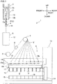
- a spun yarn take-up apparatus 1 takes up synthetic fiber yarns Y formed of filaments f spun out from a spinning apparatus 2, and forms packages P by winding the yarns Y onto bobbins B, respectively.
- the description below is given on the premise that the up-down direction, front-back direction, and left-right direction in FIG. 1 are respectively the up-down direction relative to the spun yarn take-up apparatus 1 (first direction of the present invention), the front-back direction relative to the spun yarn take-up apparatus 1, and the left-right direction relative to the spun yarn take-up apparatus 1 (second direction of the present invention).
- the spun yarn take-up apparatus 1 includes members such as a cooling unit 3, an oil supply unit 4, a drawing unit 5, take-up rollers 6 and 7, an interlacing device 8, and a winding device 9.
- a polymer supplier (not illustrated), which is a gear pump, for example, is extruded downward through spinnerets 2a which are lined up in the left-right direction (the direction away from the viewer of FIG. 1 ).
- yarns Y formed of filaments F are spun out while being lined up in the left-right direction.
- the yarns Y spun out from the spinnerets 2a of the spinning apparatus 2 travel along a yarn path through the cooling unit 3, the oil supply unit 4, the drawing unit 5, the take-up roller 6, the interlacing device 8, and the take-up roller 7, while being lined up in the left-right direction.
- the yarns Y are distributed in the front-back direction from the take-up roller 7, and are then wound onto the bobbins B at the winding device 9.
- the cooling unit 3 includes a plurality of cylindrical cooling cylinders 10. Each cooling cylinder 10 is provided below the corresponding spinneret 2a of the spinning apparatus 2. The yarns Y spun out from the spinnerets 2a of the spinning apparatus 2 run downward in internal spaces 10a of the cooling cylinders 10, along the axial direction of the cooling cylinder 10. A flow adjustment section 10b is provided around the internal space 10a. Cooling wind supplied from an unillustrated pressurized air supplier flows into the internal space 10a while being adjusted by the flow adjustment section 10b. The flow adjustment section 10b mainly performs the adjustment in such a way that the flow rate of the cooling wind flowing into the internal space 10a is more or less even in the circumferential direction of the cooling cylinder 10.
- the oil supply unit 4 includes oil supply guides 11 which are provided below the respective cooling cylinders 10.
- the oil supply guide 11 gathers filaments F spun out from the spinneret 2a into a single yarn Y, and applies oil to the yarn Y (filaments F). The details of the oil supply guide11 will be given later.
- the drawing unit 5 is provided below the oil supply unit 4.
- the drawing unit 5 includes: a heat retaining box 12; and heating rollers (not illustrated) accommodated in the heat retaining box 12. By the heating rollers, the drawing unit 5 draws the yarns Y while heating them.
- the yarns Y drawn by the drawing unit 5 are sent to the winding device 9 by the take-up rollers 6 and 7.
- the interlacing device 8 is provided between the take-up roller 6 and the take-up roller 7 to interlace filaments F constituting each yarn Y.
- the winding device 9 includes members such as a frame 13, a turret 14, two bobbin holders 15, a supporting frame 16, a contact roller 17, and a traverse unit 18.
- the winding device 9 simultaneously winds the yarns Y sent from the take-up roller 7 onto the bobbins B by rotating the bobbin holder 15, so as to form packages P.
- the turret 14 is a disc-shaped member and is attached to the frame 13.
- the turret 14 is rotationally driven by a motor which is not illustrated.
- the two bobbin holders 15 are cantilevered by the turret 14 to extend in the front-back direction.
- cylindrical bobbins B are attached to be lined up along the axial direction of the bobbin holder 15. As the turret 14 rotates, the positions of the two bobbin holders 15 are switched between an upper winding position and a lower retracted position.
- the supporting frame 16 is a frame-shaped member which is long in the front-back direction. This supporting frame 16 is fixed to the frame 13.
- a roller supporting member 19 which is long in the front-back direction is attached to a lower part of the supporting frame 16 so as to be vertically movable relative to the supporting frame 16.
- the roller supporting member 19 supports the contact roller 17 in a rotatable manner.
- the contact roller 17 extends in the axial direction of the bobbin holders 15. As this contact roller 17 makes contact with a package P under the formation and the contact roller 17 applies a predetermined contact pressure to the package P, the shape of the package P is adjusted.
- the traverse unit 18 includes traverse guides 18a lined up in the front-back direction.
- the traverse guides 18a are driven by a motor (not illustrated) and are configured to reciprocate in the front-back direction.
- a motor not illustrated
- the yarn Y is wound onto the corresponding bobbin B while being traversed about a fulcrum guide 18b.
- the oil supply guide 11 applies oil to yarns Y each of which is made of filaments F spun out from the spinning apparatus 2.
- the oil supply guide 11 is made of a ceramic material such as alumina or zirconia, and includes a guide main body 20 as shown in FIG. 2 and FIG. 3 .
- the guide main body 20 has a surface 21 which is on the front side and extends along the up-down direction. With this surface 21, the yarn Y (filaments F) which is sent from the cooling unit 3 and runs downward (i.e., from one side to the other side in the first direction) makes contact.
- the guide main body 20 includes an oil passage 22.
- the oil passage 22 is formed in the oil supply guide 11 and extends in the front-back direction.
- the front end of the oil passage 22 is a discharge port 25 formed in the surface 21.
- the density of the oil discharged from the discharge port 25 is about 85%. This density of the oil indicates density of all active ingredients other than water, such as oil and an additive.
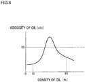
- FIG. 4 shows the relationship between oil density and oil viscosity. As shown in FIG. 4 , in oil, the viscosity of the oil typically decreases as a difference between an oil amount and a water amount increases.
- the viscosity is about 45cSt (equal to or lower than 50cSt) when the density is about 85%.
- yarn breakage tends to occur when oil with the viscosity higher than 50cSt is applied to the yarn.
- the viscosity of oil applied to the yarn Y is preferably equal to or lower than 50cSt.
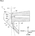
- the surface 21 of the guide main body 20 includes an upper curved surface 26 which is above the upper end 25a (end on one side in the first direction) of the discharge port 25 and a lower curved surface 27 (contact surface and curved surface of the present invention) which is below the lower end 25b (end on the other side in the first direction) of the discharge port 25.
- the curved surfaces 26 and 27 are curved to protrude outward of the guide main body 20.
- the upper end 25a of the discharge port 25 and an upper part 20a of the guide main body 20, which is above the upper end 25a of the discharge port 25, do not overlap a tangent L1 of the lower curved surface 27 at the lower end 25b of the discharge port 25. Furthermore, when viewed in the left-right direction, the upper end 25a of the discharge port 25 and the upper part 20a of the guide main body 20 do not overlap a linear line L2 which is obtained by rotating the tangent L1 clockwise in FIG. 3 (toward the upper end 25a of the discharge port 25) by 10 degrees about the lower end 25b of the discharge port 25.
- the upper end 25a and the lower end 25b of the discharge port 25 have the above-described positional relationship.
- the oil supply guide 11 is disposed so that, when viewed in the left-right direction, the tangent L1 is substantially parallel to the running direction of the yarn Y (filaments F) supplied from the cooling unit 3.
- the two yarn guiding members 23 are provided on the surface 21 of the guide main body 20, two yarn guiding members 23 are provided.
- the two yarn guiding members 23 are provided at parts of the surface 21, which are to the right of and to the left of the discharge port 25, respectively.
- the two yarn guiding members 23 are provided on the surface 21 to be on the respective sides of the discharge port 25 in the left-right direction.
- the two yarn guiding members 23 are inclined relative to the up-down direction so that, from above to below, the two yarn guiding members 23 converge toward the center in the left-right direction of the discharge port 25. For this reason, the distance between the two yarn guiding members 23 in the left-right direction decreases downward (i.e., in the direction from one side to the other side in the first direction).
- the filaments F supplied from the cooling unit 3 are guided by the two yarn guiding members 23 in directions toward the center in the left-right direction of the discharge port 25, while passing the oil supply guide 11. As a result, the filaments F are gradually converged and eventually form a single yarn Y.
- a surface 21' includes an upper curved surface 26' above an upper end 25a' of a discharge port 25' and a lower curved surface 27' below a lower end 25b' of the discharge port 25'.
- the curved surfaces 26' and 27' are curved to protrude outward of the guide main body 20'.
- an upper part 20a' of the guide main body 20' which is above the upper end 25a of the discharge port 25', overlaps a tangent L1' of the lower curved surface 27' at the lower end 25b' of the discharge port 25'.
- the yarn Y supplied from the cooling unit 3 when the yarn Y supplied from the cooling unit 3 is arranged to start to make contact with the surface 21' at the periphery of the discharge port 25', the yarn Y makes contact first with either the upper end 25a' of the discharge port 25' of the upper curved surface 26' or a part above the upper end 25a'. Thereafter, the yarn Y makes contact with a part A of the lower curved surface 27', which is below the lower end 25b' of the discharge port 25'. As the yarn Y runs from a part S' which is further below the part A of the lower curved surface 27' and runs along a tangent T' at the part S', the yarn Y leaves the lower curved surface 27'.
- the viscosity of oil is low when the density of the oil is low (e.g., equal to or lower than 30%).
- an amount of oil discharged from the discharge port 25' per unit time is small when the density of the oil is high, i.e., about 85%, as compared to the case where the density of the oil is low.
- the amount of the oil accumulated in the gap C tends to be unstable when the density of the oil is high, as compared to the case where the density of the oil is low.
- the upper end 25a of the discharge port 25 and the upper part 20a of the guide main body 20 do not overlap the tangent L1 of the lower curved surface 27 at the lower end 25b of the discharge port 25.
- the yarn Y (filaments F) supplied from the cooling unit 3 is arranged to start to contact with the surface 21 at the periphery of the discharge port 25, the yarn Y makes contact first with the lower curved surface 27 at around the lower end 25b of the discharge port 25, and does not make contact with the upper curved surface 26. Therefore a gap in which oil accumulates is not formed or is scarcely formed between the lower curved surface 27 and the yarn Y.
- the oil discharged from the discharge port 25 is directly applied to the yarn Y, and hence an amount of oil applied to the yarn Y is stable and uneven adherence to the yarn Y is less likely to occur.
- the oil supply guide 11 may be disposed so that the tangent L1 is slightly tilted relative to the running direction of the yarn Y supplied from the cooling unit 3.
- the upper end 25a of the discharge port 25 and the upper part 20a of the guide main body 20 do not overlap the linear line L2 which is obtained by rotating the tangent L1 clockwise in FIG. 3 (toward the upper end 25a of the discharge port 25) by 10 degrees about the lower end 25b of the discharge port 25.
- the yarn Y runs from a part S below a part at which the yarn Y makes contact first (i.e., the lower end 25b of the discharge port 25) and runs along a tangent T at the part S, the yarn Y leaves the lower curved surface 27.
- oil on the yarn Y is not scraped off by a corner portion when the yarn Y leaves the oil supply guide 11. This makes it possible to properly control the amount of oil applied to the yarn Y.
- FIG. 6(a) shows measurement results (Comparative Examples 1 to 3) of U% of a yarn after oil was applied thereto, when three types of oils, namely, oils G1, G2, and G3 were applied to the yarn Y by using the oil supply guide 11' in which the upper part 20a' of the guide main body 20' overlapped the tangent L1' of the lower curved surface 27' at the lower end 25b' of the discharge port 25' when viewed in the left-right direction.
- FIG. 6(b) shows measurement results (Examples 1 to 3) of U% of a yarn after oil was applied thereto, when three types of oils, namely, oils G1, G2, and G3, were applied to the yarn Y by using the oil supply guide 11 in which the upper end 25a of the discharge port 25 and the upper part 20a of the guide main body 20 did not overlap the tangent L1 of the lower curved surface 27 at the lower end 25b of the discharge port 25 when viewed in the left-right direction.
- U% of the yarn indicates the degree of variation in diameter of the yarn after the application of oil thereto.
- the diameter of the yarn varies in accordance with the amount of oil. U% decreases as the degree of uneven adherence of oil to the yarn decreases.
- the yarn used for the measurement was a polyester yarn.
- the oil G1 was oil with the density of 85[%] and the viscosity of 45[cSt].
- the oil G2 was oil with the density of 90[%] and the viscosity of 38[cSt].
- the oil G3 was oil with the density of 98[%] and the viscosity of 23[cSt].
- the measurement results of U% in Comparative Examples 1 to 3 shown in FIG. 6(a) are average values of measurement results of U% when oil supply guides 11' were prepared and oil was applied to a yarn by each of these oil supply guides 11'.
- an average curvature radius of the lower curved surface 27' was 32.6[mm].
- an average deviation in the front-back direction of the upper end 25a' forward from the lower end 25b' of the discharge port 25' was 0.055[mm].
- the measurement results of U% in Examples 1 to 3 shown in FIG. 6(b) are average values of measurement results of U% when oil supply guides 11 were prepared and oil was applied to a yarn by each of these oil supply guides 11.
- an average curvature radius of the lower curved surface 27 was 32.7[mm].
- an average deviation in the front-back direction of the upper end 25a rearward from the lower end 25b of the discharge port 25 was 0.058[mm].
- the ratio Q shown in FIG. 6(b) is a ratio of U% in each example to U% in a comparative example in which measurement was done using the same oil as in the corresponding example. It is shown that, the smaller the ratio Q is, the more the uneven adherence of oil is improved. In any of Examples 1 to 3, the ratio Q was smaller than 1, indicating that the uneven adherence of oil was restrained as compared to Comparative Examples 1 to 3.
- the disclosure is not limited to this arrangement.
- the upper end 25a of the discharge port 25 and the upper part 20a of the guide main body 20 may overlap the linear line L2 as long as they do not overlap the tangent L1.
- uneven adherence to the yarn Y is prevented at least by disposing the oil supply guide such that the tangent L1 is substantially parallel to the running direction of the filaments F (yarn Y) supplied from the cooling unit 3.
- a surface 121 on the front side of a guide main body 120 includes: a flat surface 126 which is above the upper end 125a of a discharge port 125 and constitutes the upper end of the discharge port 125; a flat surface 127 (flat surface of the present invention) which is below the lower end 125b of the discharge port 125 and constitutes the lower end of the discharge port 125; a flat surface 128 below the flat surface 127; and a flat surface 129 below the flat surface 128.
- the flat surface 126 is inclined relative to the up-down direction to form a positive slope in the rearward direction.
- the flat surface 127 is substantially parallel to the up-down direction.
- the flat surfaces 128 and 129 are inclined relative to the up-down direction to form negative slopes in the rearward direction. Relative to the up-down direction, the inclination angle of the flat surface 129 is larger than the inclination angle of the flat surface 128.
- the flat surface 127 and the flat surface 128 are connected to each other by a curved surface 130 which is curved to protrude outward of the guide main body 120.
- the flat surface 128 and the flat surface 129 are connected to each other by a curved surface 131 which is curved to protrude outward of the guide main body 120.
- a combination of the flat surfaces 127 and 128 and the curved surface 130 is equivalent to the contact surface of the present invention.
- the upper end 125a of the discharge port 125 and an upper part 120a of the guide main body 120 do not overlap a first extension plane H1 which is an extension of the flat surface 127 including the lower end 125a of the discharge port 125. Furthermore, the upper end 125a of the discharge port 125 and the upper part 120a of the guide main body 120 do not overlap a second extension plane H2 which is formed by tilting the first extension plane H1 by 10 degrees clockwise about the lower end 125b of the discharge port 125 when viewed in the direction in FIG. 7 .
- the yarn Y when the yarn Y is arranged to start to make contact with the surface 121 of the guide main body 120 at the periphery of the discharge port 125, the yarn Y makes contact with the flat surface 127 first at around the lower end 125b of the discharge port 125 and does not make contact with the flat surface 126. After running on the flat surface 127, the curved surface 130, and the flat surface 128 in order, the yarn Y leaves the surface 121 from the junction between the flat surface 128 and the curved surface 131. Also in this case, oil is evenly applied to the yarn Y because no gap is formed between the flat surface 127 and the yarn Y.
- a part of the surface 121 of the guide main body 120, which is above the upper end 125a of the discharge port 125 is the flat surface 126.
- a part of the surface 121, which is above the upper end 125a of the discharge port 125 may be a curved surface in the same manner as in the embodiment above.
- a part of the surface 21, which is above the upper end 25a of the discharge port 25, may be a flat surface in the same manner as in the modification.
- the disclosure is not limited to this arrangement.
- the flat surface 127 may be directly connected to the flat surface 128, and the junction between the flat surfaces 127 and 128 may be a corner portion.
- the flat surface 128 may be directly connected to the flat surface 129, and the junction between the flat surfaces 128 and 129 may be a corner portion.
- the disclosure is not limited to this arrangement.
- the density of the oil may be higher than 85%.
- the viscosity of the oil may not be equal to or lower than 50cSt because the density of the oil is equal to or higher than 85%.
- the viscosity of the oil may be equal to or lower than 50cSt because the density of the oil is low, i.e., equal to or lower than 30%.
- the viscosity of the oil may be equal to or lower than 50cSt even when the density of the oil is equal to or higher than 30% and equal to or lower than 85%.
- uneven adherence to the yarn Y tends to occur when the oil is applied to the yarn Y by using the oil supply guides 11' shown in FIG. 5 , in the same manner as in the embodiment above.
- the drawing unit including the heat retaining box and the heating rollers
- the disclosure is not limited to this arrangement.
- the present invention may be applied to POY production facility which does not require drawing by heating.
- the density of the oil is equal to or lower than 15% and the viscosity of the oil is equal to or lower than 50cSt.
Landscapes
- Engineering & Computer Science (AREA)
- Mechanical Engineering (AREA)
- Textile Engineering (AREA)
- Spinning Methods And Devices For Manufacturing Artificial Fibers (AREA)
Abstract
Description
- The present invention relates to an oil supply guide which applies oil to a yarn spun out from a spinning apparatus and a spun yarn take-up apparatus which includes the oil supply guide.
- An oil supply guide recited in Patent Literature 1 (Japanese Unexamined Patent Publication No.
2016-216838 Patent Literature 1 includes a discharge port through which oil is discharged and a contact surface which is in contact with a yarn. The contact surface includes a first curved surface in which the discharge port is formed and a second curved surface which is positioned below the first curved surface. The yarn makes contact with the contact surface first at the periphery of the discharge port, and leaves the contact surface as the yarn runs in a tangential direction at a predetermined position in the second curved surface. - In the oil supply guide of
Patent Literature 1, the upper end of the discharge port may protrude forward as compared to the lower end, due to reasons such as a manufacturing error. In such a case, the yarn starts to make contact with the contact surface at around the upper end of the discharge port, and a gap is formed between the yarn and the second curved surface. Oil discharged from the discharge port is accumulated in this gap, and the oil accumulated in the gap is applied to the yarn. In this regard, when the viscosity of the oil is low, the oil tends to flow down from the gap, and hence an amount of the oil in the gap tends to be varied over time. As a result, patchy adherence (uneven adherence) of the oil onto the yarn may occur. - An object of the present invention is to provide an oil supply guide which is capable of evenly applying oil to a yarn even when the viscosity of the oil is low, and to provide a spun yarn take-up apparatus including the oil supply guide.
- According to a first aspect of the invention, an oil supply guide is configured to apply oil to a yarn which is constituted by filaments spun out from a spinning apparatus, the oil supply guide comprising: a guide main body which has a surface extending along a first direction; a discharge port which is formed in the surface of the guide main body and discharges the oil; and two yarn guiding members which are provided on the surface of the guide main body to be on respective sides of the discharge port in a second direction orthogonal to the first direction, the distance between the two yarn guiding members in the second direction decreasing from one side toward the other side in the first direction, and the two yarn guiding members guiding the filaments toward the center in the second direction of the discharge port, the surface of the guide main body having a contact surface to which the yarn makes contact, the contact surface being on the other side in the first direction of the discharge port, the contact surface being a curved surface protruding outward of the guide main body, and when viewed in the second direction, an end on the one side in the first direction of the discharge port and a part of the guide main body, which is on the one side in the first direction of the end on the one side of the discharge port, do not overlap a tangent of the curved surface at an end on the other side in the first direction of the discharge port.
- Being different from the present invention, assume that, when viewed in the second direction, an end on the one side in the first direction of the discharge port or a part of the guide main body, which is on the one side in the first direction of the end on the one side of the discharge port, overlaps a tangent of the curved surface at an end on the other side in the first direction of the discharge port. In this case, when the yarn is arranged to run on the oil supply guide from one side to the other side in the first direction and to start to make contact with the surface of the oil supply guide at the periphery of the discharge port, the yarn makes contact first with the surface of the guide main body at around the end on the one side in the first direction of the discharge port. As a result, a gap is formed between the curved surface and the yarn. Oil discharged from the discharge port is accumulated in this gap, and the oil accumulated in the gap is applied to the yarn. However, when the viscosity of the oil is low and the ejection amount of the oil per unit time is small, the oil does not stay in the gap for a long time and easily drops off. As a result, the amount of the oil in the gap is unstable and patchy adherence (uneven adherence) of the oil onto the yarn Y occurs.
- In the present invention, when viewed in the second direction, the end on the one side in the first direction of the discharge port and the part of the guide main body, which is on the one side in the first direction of the end on the one side of the discharge port, do not overlap a tangent of the curved surface at an end on the other side in the first direction of the discharge port. On this account, when the yarn is arranged to run on the oil supply guide from one side to the other side in the first direction and to start to make contact with the surface of the guide main body at the periphery of the discharge port, the yarn makes contact first with the curved surface at around the end on the other side in the first direction of the discharge port. Therefore a gap in which oil accumulates is not formed or is scarcely formed between the curved surface and the yarn. On this account, oil can be evenly applied to the yarn even when the viscosity of the oil is low.
- In addition to the above, because in the present invention the contact surface is a curved surface, the yarn in contact with the curved surface leaves the curved surface as the yarn runs in the tangential direction at a part on the other side of the end on the other side of the discharge port. On this account, oil is not scraped off by a corner portion when the yarn leaves the curved surface. This makes it possible to properly control the amount of oil applied to the yarn.
- According to a second aspect of the invention, the oil supply guide of the first aspect is arranged such that, when viewed in the second direction, the end on the one side in the first direction of the discharge port and the part of the guide main body, which is on the one side in the first direction of the end on the one side of the discharge port, do not overlap a linear line which is formed by tilting the tangent by 10 degrees toward the end on the one side in the first direction of the discharge port about the end on the other side in the first direction of the discharge port.
- The oil supply guide may be disposed so that the tangent of the contact surface at the end on the other side in the first direction of the discharge port is slightly tilted relative to the running direction of the yarn. According to the present invention, when viewed in the second direction, the end on the one side in the first direction of the discharge port and the part of the guide main body, which is on the one side in the first direction of the end on the one side of the discharge port, do not overlap a linear line which is formed by tilting the tangent by 10 degrees toward the end on the one side in the first direction of the discharge port about the end on the other side in the first direction of the discharge port. With this arrangement, even if the oil supply guide is disposed so that the tangent is tilted by 10 degrees or less relative to the running direction of the yarn, the yarn starts to make contact with the curved surface at around the end on the other side in the first direction of the discharge port. Therefore a gap in which oil accumulates is not formed or is scarcely formed between the curved surface and the yarn.
- According to a third aspect of the invention, an oil supply guide is configured to apply oil to a yarn which is constituted by filaments spun out from a spinning apparatus, the oil supply guide comprising: a guide main body which has a surface extending along a first direction; a discharge port which is formed in the surface of the guide main body and discharges the oil; and two yarn guiding members which are provided on the surface of the guide main body to be on respective sides of the discharge port in a second direction orthogonal to the first direction, the distance between the two yarn guiding members in the second direction decreasing from one side toward the other side in the first direction, and the two yarn guiding members guiding the filaments toward the center in the second direction of the discharge port, the surface of the guide main body having a contact surface to which the yarn makes contact, the contact surface being on the other side in the first direction of the discharge port, the contact surface including a flat surface which forms an end on the other side in the first direction of the discharge port, and when viewed in the second direction, an end on the one side in the first direction of the discharge port and a part of the guide main body, which is on the one side in the first direction of the end on the one side of the discharge port, do not overlap a first extension plane which is an extension of the flat surface.
- Being different from the present invention, assume that, when viewed in the second direction, an end on the one side in the first direction of the discharge port or a part of the guide main body, which is on the one side in the first direction of the end on the one side of the discharge port, overlaps a first extension plane. In this case, when the yarn is arranged to run on the oil supply guide from one side to the other side in the first direction and to start to make contact with the surface of the oil supply guide at the periphery of the discharge port, the yarn makes contact first with the surface of the guide main body at around the end on the one side in the first direction of the discharge port. As a result, a gap is formed between the flat surface and the yarn. Oil discharged from the discharge port is accumulated in this gap, and the oil accumulated in the gap is applied to the yarn. However, when the viscosity of the oil is low and the ejection amount of the oil per unit time is small, the oil does not stay in the gap for a long time and easily drops off. As a result, the amount of the oil in the gap is unstable and patchy adherence (uneven adherence) of the oil onto the yarn Y occurs.
- In the present invention, when viewed in the second direction, the end on the one side in the first direction of the discharge port and the part of the guide main body, which is on the one side in the first direction of the end on the one side of the discharge port, do not overlap the first extension plane. On this account, when the yarn is arranged to run on the oil supply guide from one side to the other side in the first direction and to start to make contact with the surface of the guide main body at the periphery of the discharge port, the yarn makes contact first with the flat surface at around the end on the other side in the first direction of the discharge port. Therefore a gap in which oil accumulates is not formed or is scarcely formed between the flat surface and the yarn. On this account, oil can be evenly applied to the yarn even when the viscosity of the oil is low.
- According to a fourth aspect of the invention, the oil supply guide of the third aspect is arranged such that, when viewed in the second direction, the end on the one side in the first direction of the discharge port and the part of the guide main body, which is on the one side in the first direction of the end on the one side of the discharge port, do not overlap a second extension plane which is formed by tilting the first extension plane by 10 degrees toward the end on the one side in the first direction of the discharge port about the end on the other side in the first direction of the discharge port.
- The oil supply guide may be disposed so that the flat surface is slightly tilted relative to the running direction of the yarn. In the present invention, when viewed in the second direction, the end on the one side in the first direction of the discharge port and the part of the guide main body, which is on the one side in the first direction of the end on the one side of the discharge port, do not overlap the second extension plane. With this arrangement, even if the oil supply guide is disposed so that the flat surface is tilted by 10 degrees or less relative to the running direction of the yarn, the yarn starts to make contact with the flat surface at around the end on the other side in the first direction of the discharge port. Therefore a gap in which oil accumulates is not formed or is scarcely formed between the flat surface and the yarn.
- According to a fifth aspect of the invention, the oil supply guide of the third or fourth aspect is arranged such that, the contact surface includes a curved surface which is connected to an end on the other side in the first direction of the flat surface and is curved to protrude outward of the guide main body.
- According to the present invention, the contact surface includes a curved surface which is connected to an end on the other side in the first direction of the flat surface and is curved to protrude outward of the guide main body. On this account, the oil is not scraped off by a corner portion when the yarn in contact with the contact surface leaves the contact surface from the end on the other side in the first direction of the flat surface. This makes it possible to properly control the amount of oil applied to the yarn.
- According the a sixth aspect of the invention, a spun yarn take-up apparatus is configured to take up a yarn which is constituted by filaments spun out from a spinning apparatus, the spun yarn take-up apparatus comprising an oil supply guide which is configured to apply oil to the yarn running from one side to the other side in a first direction, the oil supply guide including: a guide main body which has a surface extending along the first direction; and a discharge port which is formed in the surface of the guide main body and discharges the oil with the viscosity of equal to or lower than 50cSt, the yarn starting to make contact with the surface at a periphery of the discharge port, the surface of the guide main body having a contact surface to which the yarn makes contact, the contact surface being on the other side in the first direction of the discharge port, the contact surface being a curved surface protruding outward of the guide main body, and when viewed in the second direction, an end on the one side in the first direction of the discharge port and a part of the guide main body, which is on the one side in the first direction of the end on the one side of the discharge port, do not overlap a tangent of the curved surface at an end on the other side in the first direction of the discharge port.
- Being different from the present invention, assume that, when viewed in the second direction, an end on the one side in the first direction of the discharge port or a part of the guide main body, which is on the one side in the first direction of the end on the one side of the discharge port, overlaps a tangent of the curved surface at an end on the other side in the first direction of the discharge port. In this case, when the yarn is arranged to run on the oil supply guide from one side to the other side in the first direction and to start to make contact with the surface of the oil supply guide at the periphery of the discharge port, the yarn makes contact first with the surface of the guide main body at around the end on the one side in the first direction of the discharge port. As a result, a gap is formed between the curved surface and the yarn. Oil discharged from the discharge port is accumulated in this gap, and the oil accumulated in the gap is applied to the yarn. However, when the viscosity of the oil is low and the ejection amount of the oil per unit time is small, the oil does not stay in the gap for a long time and easily drops off. As a result, the amount of the oil in the gap is unstable and patchy adherence (uneven adherence) of the oil onto the yarn Y occurs.
- In the present invention, when viewed in the second direction, the end on the one side in the first direction of the discharge port and the part of the guide main body, which is on the one side in the first direction of the end on the one side of the discharge port, do not overlap the tangent of the curved surface at the end on the other side in the first direction of the discharge port. On this account, when the yarn is arranged to run on the oil supply guide from one side to the other side in the first direction and to start to make contact with the surface of the guide main body at the periphery of the discharge port, the yarn makes contact first with the curved surface at around the end on the other side in the first direction of the discharge port. Therefore a gap in which oil accumulates is not formed or is scarcely formed between the curved surface and the yarn. On this account, oil can be evenly applied to the yarn even when the viscosity of the oil is low and the ejection amount of the oil per unit time is small.
- In addition to the above, because in the present invention the contact surface is a curved surface, the yarn in contact with the curved surface leaves the curved surface as the yarn runs in the tangential direction at a part on the other side of the end on the other side of the discharge port. On this account, oil is not scraped off by a corner portion when the yarn leaves the curved surface. This makes it possible to properly control the amount of oil applied to the yarn.
- According to a seventh aspect of the invention, the spun yarn take-up apparatus of the sixth aspect is arranged such that, the oil supply guide is, when viewed in the second direction, disposed so that an angle between the tangent and a running direction of the yarn immediately before making contact with the surface is equal to or smaller than 10 degrees, and the end on the one side in the first direction of the discharge port and the part of the guide main body, which is on the one side in the first direction of the end on the one side of the discharge port, do not overlap a linear line which is formed by tilting the tangent by 10 degrees toward the end on the one side in the first direction of the discharge port about the end on the other side in the first direction of the discharge port.
- The oil supply guide may be disposed so that the tangent of the contact surface at the end on the other side in the first direction of the discharge port is slightly tilted relative to the running direction of the yarn. According to the present invention, when viewed in the second direction, the end on the one side in the first direction of the discharge port and the part of the guide main body, which is on the one side in the first direction of the end on the one side of the discharge port, do not overlap a linear line which is formed by tilting the tangent by 10 degrees toward the end on the one side in the first direction of the discharge port about the end on the other side in the first direction of the discharge port. With this arrangement, even if the oil supply guide is disposed so that the tangent is tilted by 10 degrees or less relative to the running direction of the yarn, the yarn starts to make contact with the curved surface at around the end on the other side in the first direction of the discharge port. Therefore the above-described gap in which oil accumulates is not formed or is scarcely formed.
- According an eighth aspect of the invention, a spun yarn take-up apparatus is configured to take up a yarn which is constituted by filaments spun out from a spinning apparatus, the spun yarn take-up apparatus comprising an oil supply guide which is configured to apply oil to the yarn running from one side to the other side in a first direction, the oil supply guide including: a guide main body which has a surface extending along the first direction; and a discharge port which is formed in the surface of the guide main body and discharges the oil with the viscosity of equal to or lower than 50cSt, the yarn starting to make contact with the surface at a periphery of the discharge port, the surface of the guide main body having a contact surface to which the yarn makes contact, the contact surface being on the other side in the first direction of the discharge port, the contact surface including a flat surface which forms an end on the other side in the first direction of the discharge port, and when viewed in the second direction, an end on the one side in the first direction of the discharge port and a part of the guide main body, which is on the one side in the first direction of the end on the one side of the discharge port, do not overlap a first extension plane which is an extension of the flat surface.
- Being different from the present invention, assume that, when viewed in the second direction, an end on the one side in the first direction of the discharge port or a part of the guide main body, which is on the one side in the first direction of the end on the one side of the discharge port, overlaps a first extension plane. In this case, when the yarn is arranged to run on the oil supply guide from one side to the other side in the first direction and to start to make contact with the surface of the oil supply guide at the periphery of the discharge port, the yarn makes contact first with the surface of the guide main body at around the end on the one side in the first direction of the discharge port. As a result, a gap is formed between the contact surface and the yarn. Oil discharged from the discharge port is accumulated in this gap, and the oil accumulated in the gap is applied to the yarn. However, when the viscosity of the oil is low and the ejection amount of the oil per unit time is small, the oil does not stay in the gap for a long time and easily drops off. As a result, the amount of the oil in the gap is unstable and patchy adherence (uneven adherence) of the oil onto the yarn Y occurs.
- In the present invention, when viewed in the second direction, the end on the one side in the first direction of the discharge port and the part of the guide main body, which is on the one side in the first direction of the end on the one side of the discharge port, do not overlap the first extension plane. On this account, when the yarn is arranged to run on the oil supply guide from one side to the other side in the first direction and to start to make contact with the surface of the guide main body at the periphery of the discharge port, the yarn makes contact first with the flat surface at around the end on the other side in the first direction of the discharge port. Therefore a gap in which oil accumulates is not formed or is scarcely formed between the flat surface and the yarn. On this account, oil can be evenly applied to the yarn even when the viscosity of the oil is low and the ejection amount of the oil per unit time is small.
- According to a ninth aspect of the invention, the spun yarn take-up apparatus of the eighth aspect is arranged such that, the oil supply guide is, when viewed in the second direction, disposed so that an angle between the tangent and a running direction of the yarn immediately before making contact with the surface is equal to or smaller than 10 degrees, and the end on the one side in the first direction of the discharge port and the part of the guide main body, which is on the one side in the first direction of the end on the one side of the discharge port, do not overlap a second extension plane which is formed by tilting the first extension plane by 10 degrees toward the end on the one side in the first direction of the discharge port about the end on the other side in the first direction of the discharge port.
- The oil supply guide may be disposed so that the flat surface is slightly tilted relative to the running direction of the yarn. In the present invention, when viewed in the second direction, the end on the one side in the first direction of the discharge port and the part of the guide main body, which is on the one side in the first direction of the end on the one side of the discharge port, do not overlap the second extension plane. With this arrangement, even if the oil supply guide is disposed so that the flat surface is tilted by 10 degrees or less relative to the running direction of the yarn, the yarn starts to make contact with the flat surface at around the end on the other side in the first direction of the discharge port. Therefore a gap in which oil accumulates is not formed or is scarcely formed between the flat surface and the yarn.
- According to a tenth aspect of the invention, the spun yarn take-up apparatus of the eighth or ninth aspect is arranged such that, the oil supply guide includes a curved surface which is connected to an end on the other side in the first direction of the flat surface and is curved to protrude outward of the guide main body.
- According to the present invention, the contact surface includes a curved surface which is connected to an end on the other side in the first direction of the flat surface and is curved to protrude outward of the guide main body. On this account, the oil is not scraped off by a corner portion when the yarn in contact with the contact surface leaves the end on the other side in the first direction of the flat surface. This makes it possible to properly control the amount of oil applied to the yarn.
- According to an eleventh aspect of the invention, the spun yarn take-up apparatus of any one of the sixth to tenth aspects is arranged such that, the oil supply guide discharges the oil with the density of equal to or higher than 85% from the discharge port.
- The viscosity of the oil is low both when the density of the oil is low and high. However, because the required amount of oil applied to the yarn remains unchanged, an amount of oil discharged from the discharge port per unit time in order to apply a predetermined amount of oil to the yarn is small when the density of the oil is high, as compared to the case where the density of the oil is low. As a result, the amount of the accumulated in the gap tends to be unstable when the density of the oil is high. For this reason, when the density of the oil is equal to or higher than 85%, it is greatly significant to eliminate or minimize the gap in which the oil accumulates between the contact surface (curved surface or flat surface) and the yarn, by arranging the end on the one side in the first direction of the discharge port and the part of the guide main body, which is on the one side of the end on the one side of the discharge port, not to overlap the tangent or the first extension plane.
- According to the present invention, oil can be evenly applied to a yarn even when the viscosity of the oil is low.
-
-
FIG. 1 is a schematic diagram of a spun yarn take-up apparatus including an oil supply guide. -
FIG. 2 is a front elevation of the oil supply guide. -
FIG. 3 is a cross section taken along a line III-III inFIG. 2 . -
FIG. 4 shows the relationship between oil density and oil viscosity. -
FIG. 5 is equivalent toFIG. 3 and shows an oil supply guide in which the upper end of the discharge port is disposed forward as compared to the oil supply guide ofFIG. 3 . -
FIG. 6(a) shows U% in Comparative Examples 1 to 3. -
FIG. 6(b) shows U% in Examples 1 to 3.FIG. 6(c) shows the density and viscosity of oil used for measurement. -
FIG. 7 is equivalent toFIG. 3 and is a cross section of an oil supply guide of a modification. - The following will describe a preferred embodiment of the present invention.
- As shown in
FIG. 1 , a spun yarn take-upapparatus 1 takes up synthetic fiber yarns Y formed of filaments f spun out from aspinning apparatus 2, and forms packages P by winding the yarns Y onto bobbins B, respectively. The description below is given on the premise that the up-down direction, front-back direction, and left-right direction inFIG. 1 are respectively the up-down direction relative to the spun yarn take-up apparatus 1 (first direction of the present invention), the front-back direction relative to the spun yarn take-upapparatus 1, and the left-right direction relative to the spun yarn take-up apparatus 1 (second direction of the present invention). - The spun yarn take-up
apparatus 1 includes members such as acooling unit 3, anoil supply unit 4, adrawing unit 5, take-uprollers device 8, and a windingdevice 9. In thespinning apparatus 2, to begin with, polymer supplied from a polymer supplier (not illustrated), which is a gear pump, for example, is extruded downward throughspinnerets 2a which are lined up in the left-right direction (the direction away from the viewer ofFIG. 1 ). As a consequence, yarns Y formed of filaments F are spun out while being lined up in the left-right direction. - The yarns Y spun out from the
spinnerets 2a of thespinning apparatus 2 travel along a yarn path through thecooling unit 3, theoil supply unit 4, thedrawing unit 5, the take-uproller 6, the interlacingdevice 8, and the take-uproller 7, while being lined up in the left-right direction. The yarns Y are distributed in the front-back direction from the take-uproller 7, and are then wound onto the bobbins B at the windingdevice 9. - The
cooling unit 3 includes a plurality ofcylindrical cooling cylinders 10. Each coolingcylinder 10 is provided below the correspondingspinneret 2a of thespinning apparatus 2. The yarns Y spun out from thespinnerets 2a of thespinning apparatus 2 run downward ininternal spaces 10a of the coolingcylinders 10, along the axial direction of thecooling cylinder 10. Aflow adjustment section 10b is provided around theinternal space 10a. Cooling wind supplied from an unillustrated pressurized air supplier flows into theinternal space 10a while being adjusted by theflow adjustment section 10b. Theflow adjustment section 10b mainly performs the adjustment in such a way that the flow rate of the cooling wind flowing into theinternal space 10a is more or less even in the circumferential direction of thecooling cylinder 10. - The
oil supply unit 4 includes oil supply guides 11 which are provided below therespective cooling cylinders 10. Theoil supply guide 11 gathers filaments F spun out from thespinneret 2a into a single yarn Y, and applies oil to the yarn Y (filaments F). The details of the oil supply guide11 will be given later. - The
drawing unit 5 is provided below theoil supply unit 4. Thedrawing unit 5 includes: aheat retaining box 12; and heating rollers (not illustrated) accommodated in theheat retaining box 12. By the heating rollers, thedrawing unit 5 draws the yarns Y while heating them. - The yarns Y drawn by the
drawing unit 5 are sent to the windingdevice 9 by the take-uprollers device 8 is provided between the take-uproller 6 and the take-uproller 7 to interlace filaments F constituting each yarn Y. - The winding
device 9 includes members such as aframe 13, aturret 14, twobobbin holders 15, a supportingframe 16, acontact roller 17, and atraverse unit 18. The windingdevice 9 simultaneously winds the yarns Y sent from the take-uproller 7 onto the bobbins B by rotating thebobbin holder 15, so as to form packages P. - The
turret 14 is a disc-shaped member and is attached to theframe 13. Theturret 14 is rotationally driven by a motor which is not illustrated. The twobobbin holders 15 are cantilevered by theturret 14 to extend in the front-back direction. To eachbobbin holder 15, cylindrical bobbins B are attached to be lined up along the axial direction of thebobbin holder 15. As theturret 14 rotates, the positions of the twobobbin holders 15 are switched between an upper winding position and a lower retracted position. - The supporting
frame 16 is a frame-shaped member which is long in the front-back direction. This supportingframe 16 is fixed to theframe 13. Aroller supporting member 19 which is long in the front-back direction is attached to a lower part of the supportingframe 16 so as to be vertically movable relative to the supportingframe 16. Theroller supporting member 19 supports thecontact roller 17 in a rotatable manner. Thecontact roller 17 extends in the axial direction of thebobbin holders 15. As thiscontact roller 17 makes contact with a package P under the formation and thecontact roller 17 applies a predetermined contact pressure to the package P, the shape of the package P is adjusted. - The
traverse unit 18 includes traverse guides 18a lined up in the front-back direction. The traverse guides 18a are driven by a motor (not illustrated) and are configured to reciprocate in the front-back direction. As eachtraverse guide 18a to which the yarn Y is threaded reciprocates, the yarn Y is wound onto the corresponding bobbin B while being traversed about afulcrum guide 18b. - As described above, the
oil supply guide 11 applies oil to yarns Y each of which is made of filaments F spun out from thespinning apparatus 2. Theoil supply guide 11 is made of a ceramic material such as alumina or zirconia, and includes a guidemain body 20 as shown inFIG. 2 andFIG. 3 . The guidemain body 20 has asurface 21 which is on the front side and extends along the up-down direction. With thissurface 21, the yarn Y (filaments F) which is sent from thecooling unit 3 and runs downward (i.e., from one side to the other side in the first direction) makes contact. - The guide
main body 20 includes anoil passage 22. Theoil passage 22 is formed in theoil supply guide 11 and extends in the front-back direction. The front end of theoil passage 22 is adischarge port 25 formed in thesurface 21. As oil is discharged from thedischarge port 25, the oil is applied to the yarn Y (filaments F). In the present embodiment, the density of the oil discharged from thedischarge port 25 is about 85%. This density of the oil indicates density of all active ingredients other than water, such as oil and an additive.FIG. 4 shows the relationship between oil density and oil viscosity. As shown inFIG. 4 , in oil, the viscosity of the oil typically decreases as a difference between an oil amount and a water amount increases. For example, in the case of a particular type of oil, the viscosity is about 45cSt (equal to or lower than 50cSt) when the density is about 85%. As described in, for example, Japanese Patent Publication No.H7-70819 - The
surface 21 of the guidemain body 20 includes an uppercurved surface 26 which is above theupper end 25a (end on one side in the first direction) of thedischarge port 25 and a lower curved surface 27 (contact surface and curved surface of the present invention) which is below thelower end 25b (end on the other side in the first direction) of thedischarge port 25. The curved surfaces 26 and 27 are curved to protrude outward of the guidemain body 20. - When viewed in the left-right direction (i.e., in the cross section shown in
FIG. 3 ), theupper end 25a of thedischarge port 25 and anupper part 20a of the guidemain body 20, which is above theupper end 25a of thedischarge port 25, do not overlap a tangent L1 of the lowercurved surface 27 at thelower end 25b of thedischarge port 25. Furthermore, when viewed in the left-right direction, theupper end 25a of thedischarge port 25 and theupper part 20a of the guidemain body 20 do not overlap a linear line L2 which is obtained by rotating the tangent L1 clockwise inFIG. 3 (toward theupper end 25a of the discharge port 25) by 10 degrees about thelower end 25b of thedischarge port 25. - In the present embodiment, for example, because the length k between the
upper end 25a and thelower end 25b of thedischarge port 25 is about 0.1[mm] in the direction orthogonal to the tangent L1, theupper end 25a and thelower end 25b of thedischarge port 25 have the above-described positional relationship. - The
oil supply guide 11 is disposed so that, when viewed in the left-right direction, the tangent L1 is substantially parallel to the running direction of the yarn Y (filaments F) supplied from thecooling unit 3. - On the
surface 21 of the guidemain body 20, twoyarn guiding members 23 are provided. The twoyarn guiding members 23 are provided at parts of thesurface 21, which are to the right of and to the left of thedischarge port 25, respectively. In other words, the twoyarn guiding members 23 are provided on thesurface 21 to be on the respective sides of thedischarge port 25 in the left-right direction. The twoyarn guiding members 23 are inclined relative to the up-down direction so that, from above to below, the twoyarn guiding members 23 converge toward the center in the left-right direction of thedischarge port 25. For this reason, the distance between the twoyarn guiding members 23 in the left-right direction decreases downward (i.e., in the direction from one side to the other side in the first direction). The filaments F supplied from thecooling unit 3 are guided by the twoyarn guiding members 23 in directions toward the center in the left-right direction of thedischarge port 25, while passing theoil supply guide 11. As a result, the filaments F are gradually converged and eventually form a single yarn Y. - Now, being different from the present embodiment, assume that oil is applied to a yarn Y by an oil supply guide 11' shown in
FIG. 5 . In the oil supply guide 11', a surface 21' includes an upper curved surface 26' above anupper end 25a' of a discharge port 25' and a lower curved surface 27' below alower end 25b' of the discharge port 25'. The curved surfaces 26' and 27' are curved to protrude outward of the guide main body 20'. When viewed in the left-right direction (i.e., in the cross section shown inFIG. 5 ), anupper part 20a' of the guide main body 20', which is above theupper end 25a of the discharge port 25', overlaps a tangent L1' of the lower curved surface 27' at thelower end 25b' of the discharge port 25'. - In this case, when the yarn Y supplied from the
cooling unit 3 is arranged to start to make contact with the surface 21' at the periphery of the discharge port 25', the yarn Y makes contact first with either theupper end 25a' of the discharge port 25' of the upper curved surface 26' or a part above theupper end 25a'. Thereafter, the yarn Y makes contact with a part A of the lower curved surface 27', which is below thelower end 25b' of the discharge port 25'. As the yarn Y runs from a part S' which is further below the part A of the lower curved surface 27' and runs along a tangent T' at the part S', the yarn Y leaves the lower curved surface 27'. - In this case, there is a gap C between the yarn Y and a region of the lower curved surface 27', which is between the
lower end 25b' of the discharge port 25' and the part A, with the result that oil discharged from the discharge port 25' is accumulated in the gap C. The oil accumulated in the gap C is applied to the yarn Y. In this regard, when the viscosity of the oil is low and an amount of the oil discharged from the discharge port 25' per unit time is small, the oil tends to flow out without staying in the gap C for a long time. As a result, the amount of the oil accumulated in the gap C is unstable, and the amount of the oil applied to the yarn Y is unstable, too. As a result, patchy adherence (uneven adherence) of the oil onto the yarn Y occurs. In this regard, the viscosity of oil is low when the density of the oil is low (e.g., equal to or lower than 30%). However, because the required amount of oil applied to the yarn Y remains unchanged, an amount of oil discharged from the discharge port 25' per unit time is small when the density of the oil is high, i.e., about 85%, as compared to the case where the density of the oil is low. As a result, the amount of the oil accumulated in the gap C tends to be unstable when the density of the oil is high, as compared to the case where the density of the oil is low. - In an oil supply guide, when viewed in the left-right direction, if the upper end of a discharge port is on a tangent of a lower curved surface at the lower end of the discharge port, the above-described problem does not occur. However, in such an oil supply guide, with only a slight error in manufacturing, the positional relationship between the tangent of the lower curved surface at the lower end of the discharge port, the upper end of the discharge port, and an upper part of a guide main body above the upper end of the discharge port when viewed in the left-right direction easily becomes identical with the positional relationship in the oil supply guide 11'. In such a case, uneven adherence to the yarn Y may occur as in the case of the oil supply guide 11'.
- Meanwhile, in the present embodiment, when viewed in the left-right direction, the
upper end 25a of thedischarge port 25 and theupper part 20a of the guidemain body 20 do not overlap the tangent L1 of the lowercurved surface 27 at thelower end 25b of thedischarge port 25. On this account, when the yarn Y (filaments F) supplied from thecooling unit 3 is arranged to start to contact with thesurface 21 at the periphery of thedischarge port 25, the yarn Y makes contact first with the lowercurved surface 27 at around thelower end 25b of thedischarge port 25, and does not make contact with the uppercurved surface 26. Therefore a gap in which oil accumulates is not formed or is scarcely formed between the lowercurved surface 27 and the yarn Y. As a result, the oil discharged from thedischarge port 25 is directly applied to the yarn Y, and hence an amount of oil applied to the yarn Y is stable and uneven adherence to the yarn Y is less likely to occur. - The
oil supply guide 11 may be disposed so that the tangent L1 is slightly tilted relative to the running direction of the yarn Y supplied from thecooling unit 3. In this regard, in the present embodiment, when viewed in the left-right direction, theupper end 25a of thedischarge port 25 and theupper part 20a of the guidemain body 20 do not overlap the linear line L2 which is obtained by rotating the tangent L1 clockwise inFIG. 3 (toward theupper end 25a of the discharge port 25) by 10 degrees about thelower end 25b of thedischarge port 25. With this arrangement, even when theoil supply guide 11 is disposed so that the tangent L1 is tilted 10 degrees or less relative to the running direction of the yarn Y supplied from thecooling unit 3, a gap in which oil accumulates is not formed or is scarcely formed between the lowercurved surface 27 and the yarn Y in the same manner as in the case above. Therefore uneven adherence to the yarn Y is less likely to occur. - In the present embodiment, as the yarn Y runs from a part S below a part at which the yarn Y makes contact first (i.e., the
lower end 25b of the discharge port 25) and runs along a tangent T at the part S, the yarn Y leaves the lowercurved surface 27. On this account, oil on the yarn Y is not scraped off by a corner portion when the yarn Y leaves theoil supply guide 11. This makes it possible to properly control the amount of oil applied to the yarn Y. - The following will describe examples of the present invention.
-
FIG. 6(a) shows measurement results (Comparative Examples 1 to 3) of U% of a yarn after oil was applied thereto, when three types of oils, namely, oils G1, G2, and G3 were applied to the yarn Y by using the oil supply guide 11' in which theupper part 20a' of the guide main body 20' overlapped the tangent L1' of the lower curved surface 27' at thelower end 25b' of the discharge port 25' when viewed in the left-right direction. -
FIG. 6(b) shows measurement results (Examples 1 to 3) of U% of a yarn after oil was applied thereto, when three types of oils, namely, oils G1, G2, and G3, were applied to the yarn Y by using theoil supply guide 11 in which theupper end 25a of thedischarge port 25 and theupper part 20a of the guidemain body 20 did not overlap the tangent L1 of the lowercurved surface 27 at thelower end 25b of thedischarge port 25 when viewed in the left-right direction. - U% of the yarn indicates the degree of variation in diameter of the yarn after the application of oil thereto. The diameter of the yarn varies in accordance with the amount of oil. U% decreases as the degree of uneven adherence of oil to the yarn decreases. The yarn used for the measurement was a polyester yarn. As shown in
FIG. 6(c) , the oil G1 was oil with the density of 85[%] and the viscosity of 45[cSt]. The oil G2 was oil with the density of 90[%] and the viscosity of 38[cSt]. The oil G3 was oil with the density of 98[%] and the viscosity of 23[cSt]. - The measurement results of U% in Comparative Examples 1 to 3 shown in
FIG. 6(a) are average values of measurement results of U% when oil supply guides 11' were prepared and oil was applied to a yarn by each of these oil supply guides 11'. In the oil supply guides 11' used for the measurement in Comparative Examples 1 to 3, an average curvature radius of the lower curved surface 27' was 32.6[mm]. Furthermore, in the oil supply guides 11', an average deviation in the front-back direction of theupper end 25a' forward from thelower end 25b' of the discharge port 25' was 0.055[mm]. - The measurement results of U% in Examples 1 to 3 shown in
FIG. 6(b) are average values of measurement results of U% when oil supply guides 11 were prepared and oil was applied to a yarn by each of these oil supply guides 11. In the oil supply guides 11 used for the measurement in Examples 1 to 3, an average curvature radius of the lowercurved surface 27 was 32.7[mm]. Furthermore, in the oil supply guides 11, an average deviation in the front-back direction of theupper end 25a rearward from thelower end 25b of thedischarge port 25 was 0.058[mm]. - The ratio Q shown in
FIG. 6(b) is a ratio of U% in each example to U% in a comparative example in which measurement was done using the same oil as in the corresponding example. It is shown that, the smaller the ratio Q is, the more the uneven adherence of oil is improved. In any of Examples 1 to 3, the ratio Q was smaller than 1, indicating that the uneven adherence of oil was restrained as compared to Comparative Examples 1 to 3. - A preferred embodiment of the present invention has been described. It should be noted that the present invention is not limited to the above-described embodiment, and various changes, substitutions, and alterations can be made herein without departing from the spirit and scope of the invention as defined by the appended claims.
- While in the embodiment above the
upper end 25a of thedischarge port 25 and theupper part 20a of the guidemain body 20 do not overlap the linear line L2 when viewed in the left-right direction, the disclosure is not limited to this arrangement. When viewed in the left-right direction, theupper end 25a of thedischarge port 25 and theupper part 20a of the guidemain body 20 may overlap the linear line L2 as long as they do not overlap the tangent L1. Also in this case, uneven adherence to the yarn Y is prevented at least by disposing the oil supply guide such that the tangent L1 is substantially parallel to the running direction of the filaments F (yarn Y) supplied from thecooling unit 3. - While in the embodiment above a part of the
surface 21 of the guidemain body 20, which is positioned below thelower end 25b of thedischarge port 25, is the lowercurved surface 27, the disclosure is not limited to this arrangement. According to a modification, as shown inFIG. 7 , in anoil supply guide 101, asurface 121 on the front side of a guidemain body 120 includes: aflat surface 126 which is above theupper end 125a of adischarge port 125 and constitutes the upper end of thedischarge port 125; a flat surface 127 (flat surface of the present invention) which is below thelower end 125b of thedischarge port 125 and constitutes the lower end of thedischarge port 125; aflat surface 128 below theflat surface 127; and aflat surface 129 below theflat surface 128. Theflat surface 126 is inclined relative to the up-down direction to form a positive slope in the rearward direction. Theflat surface 127 is substantially parallel to the up-down direction. Theflat surfaces flat surface 129 is larger than the inclination angle of theflat surface 128. Theflat surface 127 and theflat surface 128 are connected to each other by acurved surface 130 which is curved to protrude outward of the guidemain body 120. Theflat surface 128 and theflat surface 129 are connected to each other by acurved surface 131 which is curved to protrude outward of the guidemain body 120. In this modification, a combination of theflat surfaces curved surface 130 is equivalent to the contact surface of the present invention. - In the modification, the
upper end 125a of thedischarge port 125 and anupper part 120a of the guidemain body 120, which is above theupper end 125a of thedischarge port 125, do not overlap a first extension plane H1 which is an extension of theflat surface 127 including thelower end 125a of thedischarge port 125. Furthermore, theupper end 125a of thedischarge port 125 and theupper part 120a of the guidemain body 120 do not overlap a second extension plane H2 which is formed by tilting the first extension plane H1 by 10 degrees clockwise about thelower end 125b of thedischarge port 125 when viewed in the direction inFIG. 7 . - In this case, when the yarn Y is arranged to start to make contact with the
surface 121 of the guidemain body 120 at the periphery of thedischarge port 125, the yarn Y makes contact with theflat surface 127 first at around thelower end 125b of thedischarge port 125 and does not make contact with theflat surface 126. After running on theflat surface 127, thecurved surface 130, and theflat surface 128 in order, the yarn Y leaves thesurface 121 from the junction between theflat surface 128 and thecurved surface 131. Also in this case, oil is evenly applied to the yarn Y because no gap is formed between theflat surface 127 and the yarn Y. - In the modification, because the
flat surface 127 is connected with theflat surface 128 by thecurved surface 130, oil on the yarn Y is not scraped off by a corner portion when the yarn Y runs from theflat surface 127 to the flat surface 128 (i.e., when the yarn Y leaves the lower end of the flat surface 127). Because theflat surface 128 is connected with theflat surface 129 by thecurved surface 131, the yarn Y leaves thesurface 121 in the tangential direction at the junction between thecurved surface 131 and theflat surface 128. On this account, oil on the yarn Y is not scraped off by a corner portion when the yarn Y leaves the lower end of theflat surface 128. This makes it possible to properly control the amount of oil applied to the yarn Y. - In the modification, a part of the
surface 121 of the guidemain body 120, which is above theupper end 125a of thedischarge port 125, is theflat surface 126. Alternatively, a part of thesurface 121, which is above theupper end 125a of thedischarge port 125, may be a curved surface in the same manner as in the embodiment above. Furthermore, in the embodiment above, a part of thesurface 21, which is above theupper end 25a of thedischarge port 25, may be a flat surface in the same manner as in the modification. - In addition to the above, while in the modification the
flat surface 127 and theflat surface 128 are connected by thecurved surface 130 and theflat surface 128 and theflat surface 129 are connected by thecurved surface 131, the disclosure is not limited to this arrangement. Theflat surface 127 may be directly connected to theflat surface 128, and the junction between theflat surfaces flat surface 128 may be directly connected to theflat surface 129, and the junction between theflat surfaces - While in the embodiment above the density of the oil is about 85%, the disclosure is not limited to this arrangement. The density of the oil may be higher than 85%. Furthermore, the viscosity of the oil may not be equal to or lower than 50cSt because the density of the oil is equal to or higher than 85%. For example, the viscosity of the oil may be equal to or lower than 50cSt because the density of the oil is low, i.e., equal to or lower than 30%. Furthermore, the viscosity of the oil may be equal to or lower than 50cSt even when the density of the oil is equal to or higher than 30% and equal to or lower than 85%. Also in these cases, uneven adherence to the yarn Y tends to occur when the oil is applied to the yarn Y by using the oil supply guides 11' shown in
FIG. 5 , in the same manner as in the embodiment above. - While in the embodiment above the drawing unit including the heat retaining box and the heating rollers is provided, the disclosure is not limited to this arrangement. For example, the present invention may be applied to POY production facility which does not require drawing by heating. In such a case, for example, the density of the oil is equal to or lower than 15% and the viscosity of the oil is equal to or lower than 50cSt.
Claims (11)
- An oil supply guide configured to apply oil to a yarn which is constituted by filaments spun out from a spinning apparatus, the oil supply guide comprising:a guide main body which has a surface extending along a first direction;a discharge port which is formed in the surface of the guide main body and discharges the oil; andtwo yarn guiding members which are provided on the surface of the guide main body to be on respective sides of the discharge port in a second direction orthogonal to the first direction, the distance between the two yarn guiding members in the second direction decreasing from one side toward the other side in the first direction, and the two yarn guiding members guiding the filaments toward the center in the second direction of the discharge port,the surface of the guide main body having a contact surface to which the yarn makes contact, the contact surface being on the other side in the first direction of the discharge port,the contact surface being a curved surface protruding outward of the guide main body, andwhen viewed in the second direction,an end on the one side in the first direction of the discharge port and a part of the guide main body, which is on the one side in the first direction of the end on the one side of the discharge port,do not overlap a tangent of the curved surface at an end on the other side in the first direction of the discharge port.
- The oil supply guide according to claim 1, wherein,
when viewed in the second direction,
the end on the one side in the first direction of the discharge port and the part of the guide main body, which is on the one side in the first direction of the end on the one side of the discharge port,
do not overlap a linear line which is formed by tilting the tangent by 10 degrees toward the end on the one side in the first direction of the discharge port about the end on the other side in the first direction of the discharge port. - An oil supply guide configured to apply oil to a yarn which is constituted by filaments spun out from a spinning apparatus, the oil supply guide comprising:a guide main body which has a surface extending along a first direction;a discharge port which is formed in the surface of the guide main body and discharges the oil; andtwo yarn guiding members which are provided on the surface of the guide main body to be on respective sides of the discharge port in a second direction orthogonal to the first direction, the distance between the two yarn guiding members in the second direction decreasing from one side toward the other side in the first direction, and the two yarn guiding members guiding the filaments toward the center in the second direction of the discharge port,the surface of the guide main body having a contact surface to which the yarn makes contact, the contact surface being on the other side in the first direction of the discharge port,the contact surface including a flat surface which forms an end on the other side in the first direction of the discharge port, andwhen viewed in the second direction,an end on the one side in the first direction of the discharge port and a part of the guide main body, which is on the one side in the first direction of the end on the one side of the discharge port,do not overlap a first extension plane which is an extension of the flat surface.
- The oil supply guide according to claim 3, wherein,
when viewed in the second direction,
the end on the one side in the first direction of the discharge port and the part of the guide main body, which is on the one side in the first direction of the end on the one side of the discharge port,
do not overlap a second extension plane which is formed by tilting the first extension plane by 10 degrees toward the end on the one side in the first direction of the discharge port about the end on the other side in the first direction of the discharge port. - The oil supply guide according to claim 3 or 4, wherein, the contact surface includes a curved surface which is connected to an end on the other side in the first direction of the flat surface and is curved to protrude outward of the guide main body.
- A spun yarn take-up apparatus configured to take up a yarn which is constituted by filaments spun out from a spinning apparatus,
the spun yarn take-up apparatus comprising an oil supply guide which is configured to apply oil to the yarn running from one side to the other side in a first direction,
the oil supply guide including:a guide main body which has a surface extending along the first direction; anda discharge port which is formed in the surface of the guide main body and discharges the oil with the viscosity of equal to or lower than 50cSt,the yarn starting to make contact with the surface at a periphery of the discharge port,the surface of the guide main body having a contact surface to which the yarn makes contact, the contact surface being on the other side in the first direction of the discharge port,the contact surface being a curved surface protruding outward of the guide main body, andwhen viewed in the second direction,an end on the one side in the first direction of the discharge port and a part of the guide main body, which is on the one side in the first direction of the end on the one side of the discharge port,do not overlap a tangent of the curved surface at an end on the other side in the first direction of the discharge port. - The spun yarn take-up apparatus according to claim 6, wherein,
the oil supply guide is,
when viewed in the second direction,
disposed so that an angle between the tangent and a running direction of the yarn immediately before making contact with the surface is equal to or smaller than 10 degrees, and
the end on the one side in the first direction of the discharge port and the part of the guide main body, which is on the one side in the first direction of the end on the one side of the discharge port,
do not overlap a linear line which is formed by tilting the tangent by 10 degrees toward the end on the one side in the first direction of the discharge port about the end on the other side in the first direction of the discharge port. - A spun yarn take-up apparatus configured to take up a yarn which is constituted by filaments spun out from a spinning apparatus,
the spun yarn take-up apparatus comprising an oil supply guide which is configured to apply oil to the yarn running from one side to the other side in a first direction,
the oil supply guide including:a guide main body which has a surface extending along the first direction; anda discharge port which is formed in the surface of the guide main body and discharges the oil with the viscosity of equal to or lower than 50cSt,the yarn starting to make contact with the surface at a periphery of the discharge port,the surface of the guide main body having a contact surface to which the yarn makes contact, the contact surface being on the other side in the first direction of the discharge port,the contact surface including a flat surface which forms an end on the other side in the first direction of the discharge port, andwhen viewed in the second direction,an end on the one side in the first direction of the discharge port and a part of the guide main body, which is on the one side in the first direction of the end on the one side of the discharge port,do not overlap a first extension plane which is an extension of the flat surface. - The spun yarn take-up apparatus according to claim 8, wherein,
the oil supply guide is,
when viewed in the second direction,
disposed so that an angle between the tangent and a running direction of the yarn immediately before making contact with the surface is equal to or smaller than 10 degrees, and
the end on the one side in the first direction of the discharge port and the part of the guide main body, which is on the one side in the first direction of the end on the one side of the discharge port,
do not overlap a second extension plane which is formed by tilting the first extension plane by 10 degrees toward the end on the one side in the first direction of the discharge port about the end on the other side in the first direction of the discharge port. - The spun yarn take-up machine according to claim 8 or 9, wherein,
the oil supply guide includes
a curved surface which is connected to an end on the other side in the first direction of the flat surface and is curved to protrude outward of the guide main body. - The spun yarn take-up apparatus according to any one of claims 6 to 10, wherein, the oil supply guide discharges the oil with the density of equal to or higher than 85% from the discharge port.
Applications Claiming Priority (1)
| Application Number | Priority Date | Filing Date | Title |
|---|---|---|---|
| JP2018017965A JP7186006B2 (en) | 2018-02-05 | 2018-02-05 | Lubrication guide and spinning take-up device |
Publications (2)
| Publication Number | Publication Date |
|---|---|
| EP3521486A1 true EP3521486A1 (en) | 2019-08-07 |
| EP3521486B1 EP3521486B1 (en) | 2020-12-30 |
Family
ID=65019324
Family Applications (1)
| Application Number | Title | Priority Date | Filing Date |
|---|---|---|---|
| EP19151154.2A Active EP3521486B1 (en) | 2018-02-05 | 2019-01-10 | Oil supply guide and spun yarn take-up apparatus |
Country Status (5)
| Country | Link |
|---|---|
| EP (1) | EP3521486B1 (en) |
| JP (1) | JP7186006B2 (en) |
| KR (1) | KR102464606B1 (en) |
| CN (1) | CN110117827B (en) |
| TW (1) | TWI744590B (en) |
Cited By (2)
| Publication number | Priority date | Publication date | Assignee | Title |
|---|---|---|---|---|
| EP3865444A1 (en) * | 2020-02-12 | 2021-08-18 | TMT Machinery, Inc. | Oil applying guide and spun yarn take-up machine |
| EP4717648A1 (en) * | 2024-09-30 | 2026-04-01 | TMT Machinery, Inc. | Yarn processing apparatus |
Families Citing this family (3)
| Publication number | Priority date | Publication date | Assignee | Title |
|---|---|---|---|---|
| JP2023098125A (en) | 2021-12-28 | 2023-07-10 | Tmtマシナリー株式会社 | Lubrication guides, textile machines and false twisting machines |
| JP7845935B2 (en) | 2022-07-11 | 2026-04-14 | Tmtマシナリー株式会社 | Textile machinery |
| CN119020871B (en) * | 2024-09-29 | 2026-05-29 | 北京中纺瑞海化纤技术有限公司 | Oil nozzle for chemical fiber production and application method thereof |
Citations (4)
| Publication number | Priority date | Publication date | Assignee | Title |
|---|---|---|---|---|
| JPH0770819A (en) | 1993-08-25 | 1995-03-14 | Teijin Ltd | Method for producing polyester fiber |
| JP2007009342A (en) * | 2005-06-28 | 2007-01-18 | Teijin Fibers Ltd | Method for producing synthetic multifilament yarn |
| EP3093378A1 (en) * | 2015-05-15 | 2016-11-16 | TMT Machinery, Inc. | Oil supply guide and spun yarn take-up apparatus |
| DE102016005925A1 (en) * | 2015-07-21 | 2017-01-26 | Oerlikon Textile Gmbh & Co. Kg | Preparation thread guide |
Family Cites Families (8)
| Publication number | Priority date | Publication date | Assignee | Title |
|---|---|---|---|---|
| KR100270256B1 (en) | 1994-12-28 | 2000-10-16 | 구광시 | Emulsion Lubricator for Synthetic Fibers |
| KR960023291A (en) * | 1994-12-30 | 1996-07-18 | 배도 | Injection nozzle for melt spinning oil supply |
| JP3750343B2 (en) * | 1998-03-31 | 2006-03-01 | 東レ株式会社 | Synthetic fiber oiling method |
| JP2000045121A (en) * | 1998-07-27 | 2000-02-15 | Teijin Ltd | Oil agent application guide |
| JP2002105740A (en) | 2000-09-22 | 2002-04-10 | Murata Mach Ltd | Oiling nozzle |
| TW200301324A (en) * | 2001-12-27 | 2003-07-01 | Toyo Boseki | Spinneret for synthetic fiber, oil supply device, manufacturing device and method |
| JP2008303497A (en) * | 2007-06-07 | 2008-12-18 | Jtc:Kk | Oil supply guide |
| CN102199799A (en) * | 2011-05-24 | 2011-09-28 | 无锡市太极实业股份有限公司 | Oil applying system and method for yarn activating production of polyester industrial yarns |
-
2018
- 2018-02-05 JP JP2018017965A patent/JP7186006B2/en active Active
- 2018-12-25 CN CN201811588562.7A patent/CN110117827B/en active Active
-
2019
- 2019-01-02 TW TW108100019A patent/TWI744590B/en active
- 2019-01-10 EP EP19151154.2A patent/EP3521486B1/en active Active
- 2019-01-21 KR KR1020190007371A patent/KR102464606B1/en active Active
Patent Citations (5)
| Publication number | Priority date | Publication date | Assignee | Title |
|---|---|---|---|---|
| JPH0770819A (en) | 1993-08-25 | 1995-03-14 | Teijin Ltd | Method for producing polyester fiber |
| JP2007009342A (en) * | 2005-06-28 | 2007-01-18 | Teijin Fibers Ltd | Method for producing synthetic multifilament yarn |
| EP3093378A1 (en) * | 2015-05-15 | 2016-11-16 | TMT Machinery, Inc. | Oil supply guide and spun yarn take-up apparatus |
| JP2016216838A (en) | 2015-05-15 | 2016-12-22 | Tmtマシナリー株式会社 | Oiling guide and spinning take-up device |
| DE102016005925A1 (en) * | 2015-07-21 | 2017-01-26 | Oerlikon Textile Gmbh & Co. Kg | Preparation thread guide |
Cited By (3)
| Publication number | Priority date | Publication date | Assignee | Title |
|---|---|---|---|---|
| EP3865444A1 (en) * | 2020-02-12 | 2021-08-18 | TMT Machinery, Inc. | Oil applying guide and spun yarn take-up machine |
| TWI815079B (en) * | 2020-02-12 | 2023-09-11 | 日商Tmt機械股份有限公司 | Oil applying guide and spun yarn take-up machine |
| EP4717648A1 (en) * | 2024-09-30 | 2026-04-01 | TMT Machinery, Inc. | Yarn processing apparatus |
Also Published As
| Publication number | Publication date |
|---|---|
| KR20190095116A (en) | 2019-08-14 |
| EP3521486B1 (en) | 2020-12-30 |
| KR102464606B1 (en) | 2022-11-10 |
| TW201934822A (en) | 2019-09-01 |
| JP7186006B2 (en) | 2022-12-08 |
| JP2019135335A (en) | 2019-08-15 |
| CN110117827B (en) | 2022-06-14 |
| CN110117827A (en) | 2019-08-13 |
| TWI744590B (en) | 2021-11-01 |
Similar Documents
| Publication | Publication Date | Title |
|---|---|---|
| EP3521486B1 (en) | Oil supply guide and spun yarn take-up apparatus | |
| US7802977B2 (en) | Apparatus for melt spinning and windup of synthetic yarn | |
| EP2407408B1 (en) | Filament yarn winding apparatus | |
| CN115029805B (en) | Device for drawing out and winding up a plurality of threads | |
| EP3093378B1 (en) | Oil supply guide and spun yarn take-up apparatus | |
| EP3498898A1 (en) | Interlacing device | |
| EP2636624A2 (en) | Take-up apparatus | |
| CN107428488B (en) | winding machine | |
| CN101065306A (en) | Winder Workstation | |
| EA038004B1 (en) | Method and device for winding a spun thread, in particular a glass thread in order to form a bobbin | |
| CN211444509U (en) | Cheese oiling device and cone winder | |
| US6895736B2 (en) | Thread-guiding device for collecting spun yarns on bobbins particularly for open-end spinning frames | |
| JP2011144019A (en) | Yarn winder equipment | |
| EA013532B1 (en) | Winding frame with monitored secondary travel | |
| CN216947450U (en) | Spinning equipment suitable for lining coating | |
| US4731217A (en) | Method for melt spinning thermoplastic filament yarn | |
| JP6337569B2 (en) | Yarn winding device and yarn winding method | |
| EP4624403A1 (en) | Yarn winding apparatus | |
| JPH10316311A (en) | Carbon fiber package and method of manufacturing the same | |
| CN119079675B (en) | A method for improving the forming quality of polyester drawn yarn | |
| US20250002291A1 (en) | Thread guide device for a winding apparatus | |
| CN120379915A (en) | Method for producing a winding bobbin from synthetic yarn | |
| EP0121302A1 (en) | Apparatus for taking-up filamentary yarn | |
| JPS636462B2 (en) | ||
| CN112593306A (en) | Spinning production equipment |
Legal Events
| Date | Code | Title | Description |
|---|---|---|---|
| PUAI | Public reference made under article 153(3) epc to a published international application that has entered the european phase |
Free format text: ORIGINAL CODE: 0009012 |
|
| STAA | Information on the status of an ep patent application or granted ep patent |
Free format text: STATUS: THE APPLICATION HAS BEEN PUBLISHED |
|
| AK | Designated contracting states |
Kind code of ref document: A1 Designated state(s): AL AT BE BG CH CY CZ DE DK EE ES FI FR GB GR HR HU IE IS IT LI LT LU LV MC MK MT NL NO PL PT RO RS SE SI SK SM TR |
|
| AX | Request for extension of the european patent |
Extension state: BA ME |
|
| STAA | Information on the status of an ep patent application or granted ep patent |
Free format text: STATUS: REQUEST FOR EXAMINATION WAS MADE |
|
| 17P | Request for examination filed |
Effective date: 20191125 |
|
| RBV | Designated contracting states (corrected) |
Designated state(s): AL AT BE BG CH CY CZ DE DK EE ES FI FR GB GR HR HU IE IS IT LI LT LU LV MC MK MT NL NO PL PT RO RS SE SI SK SM TR |
|
| GRAP | Despatch of communication of intention to grant a patent |
Free format text: ORIGINAL CODE: EPIDOSNIGR1 |
|
| STAA | Information on the status of an ep patent application or granted ep patent |
Free format text: STATUS: GRANT OF PATENT IS INTENDED |
|
| INTG | Intention to grant announced |
Effective date: 20200921 |
|
| GRAS | Grant fee paid |
Free format text: ORIGINAL CODE: EPIDOSNIGR3 |
|
| GRAA | (expected) grant |
Free format text: ORIGINAL CODE: 0009210 |
|
| STAA | Information on the status of an ep patent application or granted ep patent |
Free format text: STATUS: THE PATENT HAS BEEN GRANTED |
|
| AK | Designated contracting states |
Kind code of ref document: B1 Designated state(s): AL AT BE BG CH CY CZ DE DK EE ES FI FR GB GR HR HU IE IS IT LI LT LU LV MC MK MT NL NO PL PT RO RS SE SI SK SM TR |
|
| REG | Reference to a national code |
Ref country code: GB Ref legal event code: FG4D |
|
| REG | Reference to a national code |
Ref country code: AT Ref legal event code: REF Ref document number: 1350003 Country of ref document: AT Kind code of ref document: T Effective date: 20210115 |
|
| REG | Reference to a national code |
Ref country code: DE Ref legal event code: R096 Ref document number: 602019001891 Country of ref document: DE |
|
| REG | Reference to a national code |
Ref country code: IE Ref legal event code: FG4D |
|
| PG25 | Lapsed in a contracting state [announced via postgrant information from national office to epo] |
Ref country code: FI Free format text: LAPSE BECAUSE OF FAILURE TO SUBMIT A TRANSLATION OF THE DESCRIPTION OR TO PAY THE FEE WITHIN THE PRESCRIBED TIME-LIMIT Effective date: 20201230 Ref country code: RS Free format text: LAPSE BECAUSE OF FAILURE TO SUBMIT A TRANSLATION OF THE DESCRIPTION OR TO PAY THE FEE WITHIN THE PRESCRIBED TIME-LIMIT Effective date: 20201230 Ref country code: NO Free format text: LAPSE BECAUSE OF FAILURE TO SUBMIT A TRANSLATION OF THE DESCRIPTION OR TO PAY THE FEE WITHIN THE PRESCRIBED TIME-LIMIT Effective date: 20210330 Ref country code: GR Free format text: LAPSE BECAUSE OF FAILURE TO SUBMIT A TRANSLATION OF THE DESCRIPTION OR TO PAY THE FEE WITHIN THE PRESCRIBED TIME-LIMIT Effective date: 20210331 |
|
| REG | Reference to a national code |
Ref country code: AT Ref legal event code: MK05 Ref document number: 1350003 Country of ref document: AT Kind code of ref document: T Effective date: 20201230 |
|
| PG25 | Lapsed in a contracting state [announced via postgrant information from national office to epo] |
Ref country code: LV Free format text: LAPSE BECAUSE OF FAILURE TO SUBMIT A TRANSLATION OF THE DESCRIPTION OR TO PAY THE FEE WITHIN THE PRESCRIBED TIME-LIMIT Effective date: 20201230 Ref country code: SE Free format text: LAPSE BECAUSE OF FAILURE TO SUBMIT A TRANSLATION OF THE DESCRIPTION OR TO PAY THE FEE WITHIN THE PRESCRIBED TIME-LIMIT Effective date: 20201230 Ref country code: BG Free format text: LAPSE BECAUSE OF FAILURE TO SUBMIT A TRANSLATION OF THE DESCRIPTION OR TO PAY THE FEE WITHIN THE PRESCRIBED TIME-LIMIT Effective date: 20210330 |
|
| REG | Reference to a national code |
Ref country code: NL Ref legal event code: MP Effective date: 20201230 |
|
| PG25 | Lapsed in a contracting state [announced via postgrant information from national office to epo] |
Ref country code: HR Free format text: LAPSE BECAUSE OF FAILURE TO SUBMIT A TRANSLATION OF THE DESCRIPTION OR TO PAY THE FEE WITHIN THE PRESCRIBED TIME-LIMIT Effective date: 20201230 |
|
| REG | Reference to a national code |
Ref country code: LT Ref legal event code: MG9D |
|
| PG25 | Lapsed in a contracting state [announced via postgrant information from national office to epo] |
Ref country code: EE Free format text: LAPSE BECAUSE OF FAILURE TO SUBMIT A TRANSLATION OF THE DESCRIPTION OR TO PAY THE FEE WITHIN THE PRESCRIBED TIME-LIMIT Effective date: 20201230 Ref country code: CZ Free format text: LAPSE BECAUSE OF FAILURE TO SUBMIT A TRANSLATION OF THE DESCRIPTION OR TO PAY THE FEE WITHIN THE PRESCRIBED TIME-LIMIT Effective date: 20201230 Ref country code: SK Free format text: LAPSE BECAUSE OF FAILURE TO SUBMIT A TRANSLATION OF THE DESCRIPTION OR TO PAY THE FEE WITHIN THE PRESCRIBED TIME-LIMIT Effective date: 20201230 Ref country code: RO Free format text: LAPSE BECAUSE OF FAILURE TO SUBMIT A TRANSLATION OF THE DESCRIPTION OR TO PAY THE FEE WITHIN THE PRESCRIBED TIME-LIMIT Effective date: 20201230 Ref country code: PT Free format text: LAPSE BECAUSE OF FAILURE TO SUBMIT A TRANSLATION OF THE DESCRIPTION OR TO PAY THE FEE WITHIN THE PRESCRIBED TIME-LIMIT Effective date: 20210430 Ref country code: LT Free format text: LAPSE BECAUSE OF FAILURE TO SUBMIT A TRANSLATION OF THE DESCRIPTION OR TO PAY THE FEE WITHIN THE PRESCRIBED TIME-LIMIT Effective date: 20201230 |
|
| PG25 | Lapsed in a contracting state [announced via postgrant information from national office to epo] |
Ref country code: AT Free format text: LAPSE BECAUSE OF FAILURE TO SUBMIT A TRANSLATION OF THE DESCRIPTION OR TO PAY THE FEE WITHIN THE PRESCRIBED TIME-LIMIT Effective date: 20201230 Ref country code: PL Free format text: LAPSE BECAUSE OF FAILURE TO SUBMIT A TRANSLATION OF THE DESCRIPTION OR TO PAY THE FEE WITHIN THE PRESCRIBED TIME-LIMIT Effective date: 20201230 |
|
| PG25 | Lapsed in a contracting state [announced via postgrant information from national office to epo] |
Ref country code: LU Free format text: LAPSE BECAUSE OF NON-PAYMENT OF DUE FEES Effective date: 20210110 Ref country code: IS Free format text: LAPSE BECAUSE OF FAILURE TO SUBMIT A TRANSLATION OF THE DESCRIPTION OR TO PAY THE FEE WITHIN THE PRESCRIBED TIME-LIMIT Effective date: 20210430 |
|
| REG | Reference to a national code |
Ref country code: DE Ref legal event code: R097 Ref document number: 602019001891 Country of ref document: DE |
|
| REG | Reference to a national code |
Ref country code: BE Ref legal event code: MM Effective date: 20210131 |
|
| PG25 | Lapsed in a contracting state [announced via postgrant information from national office to epo] |
Ref country code: AL Free format text: LAPSE BECAUSE OF FAILURE TO SUBMIT A TRANSLATION OF THE DESCRIPTION OR TO PAY THE FEE WITHIN THE PRESCRIBED TIME-LIMIT Effective date: 20201230 Ref country code: IT Free format text: LAPSE BECAUSE OF FAILURE TO SUBMIT A TRANSLATION OF THE DESCRIPTION OR TO PAY THE FEE WITHIN THE PRESCRIBED TIME-LIMIT Effective date: 20201230 Ref country code: MC Free format text: LAPSE BECAUSE OF FAILURE TO SUBMIT A TRANSLATION OF THE DESCRIPTION OR TO PAY THE FEE WITHIN THE PRESCRIBED TIME-LIMIT Effective date: 20201230 |
|
| PLBE | No opposition filed within time limit |
Free format text: ORIGINAL CODE: 0009261 |
|
| STAA | Information on the status of an ep patent application or granted ep patent |
Free format text: STATUS: NO OPPOSITION FILED WITHIN TIME LIMIT |
|
| PG25 | Lapsed in a contracting state [announced via postgrant information from national office to epo] |
Ref country code: DK Free format text: LAPSE BECAUSE OF FAILURE TO SUBMIT A TRANSLATION OF THE DESCRIPTION OR TO PAY THE FEE WITHIN THE PRESCRIBED TIME-LIMIT Effective date: 20201230 |
|
| 26N | No opposition filed |
Effective date: 20211001 |
|
| PG25 | Lapsed in a contracting state [announced via postgrant information from national office to epo] |
Ref country code: FR Free format text: LAPSE BECAUSE OF NON-PAYMENT OF DUE FEES Effective date: 20210228 Ref country code: IE Free format text: LAPSE BECAUSE OF NON-PAYMENT OF DUE FEES Effective date: 20210110 Ref country code: ES Free format text: LAPSE BECAUSE OF FAILURE TO SUBMIT A TRANSLATION OF THE DESCRIPTION OR TO PAY THE FEE WITHIN THE PRESCRIBED TIME-LIMIT Effective date: 20201230 |
|
| PG25 | Lapsed in a contracting state [announced via postgrant information from national office to epo] |
Ref country code: SI Free format text: LAPSE BECAUSE OF FAILURE TO SUBMIT A TRANSLATION OF THE DESCRIPTION OR TO PAY THE FEE WITHIN THE PRESCRIBED TIME-LIMIT Effective date: 20201230 |
|
| PG25 | Lapsed in a contracting state [announced via postgrant information from national office to epo] |
Ref country code: IS Free format text: LAPSE BECAUSE OF FAILURE TO SUBMIT A TRANSLATION OF THE DESCRIPTION OR TO PAY THE FEE WITHIN THE PRESCRIBED TIME-LIMIT Effective date: 20210430 |
|
| PG25 | Lapsed in a contracting state [announced via postgrant information from national office to epo] |
Ref country code: BE Free format text: LAPSE BECAUSE OF NON-PAYMENT OF DUE FEES Effective date: 20210131 |
|
| REG | Reference to a national code |
Ref country code: CH Ref legal event code: PL |
|
| PG25 | Lapsed in a contracting state [announced via postgrant information from national office to epo] |
Ref country code: LI Free format text: LAPSE BECAUSE OF NON-PAYMENT OF DUE FEES Effective date: 20220131 Ref country code: CH Free format text: LAPSE BECAUSE OF NON-PAYMENT OF DUE FEES Effective date: 20220131 |
|
| P01 | Opt-out of the competence of the unified patent court (upc) registered |
Effective date: 20230426 |
|
| PG25 | Lapsed in a contracting state [announced via postgrant information from national office to epo] |
Ref country code: NL Free format text: LAPSE BECAUSE OF NON-PAYMENT OF DUE FEES Effective date: 20201230 Ref country code: CY Free format text: LAPSE BECAUSE OF FAILURE TO SUBMIT A TRANSLATION OF THE DESCRIPTION OR TO PAY THE FEE WITHIN THE PRESCRIBED TIME-LIMIT Effective date: 20201230 |
|
| PG25 | Lapsed in a contracting state [announced via postgrant information from national office to epo] |
Ref country code: SM Free format text: LAPSE BECAUSE OF FAILURE TO SUBMIT A TRANSLATION OF THE DESCRIPTION OR TO PAY THE FEE WITHIN THE PRESCRIBED TIME-LIMIT Effective date: 20201230 Ref country code: HU Free format text: LAPSE BECAUSE OF FAILURE TO SUBMIT A TRANSLATION OF THE DESCRIPTION OR TO PAY THE FEE WITHIN THE PRESCRIBED TIME-LIMIT; INVALID AB INITIO Effective date: 20190110 |
|
| GBPC | Gb: european patent ceased through non-payment of renewal fee |
Effective date: 20230110 |
|
| PG25 | Lapsed in a contracting state [announced via postgrant information from national office to epo] |
Ref country code: GB Free format text: LAPSE BECAUSE OF NON-PAYMENT OF DUE FEES Effective date: 20230110 |
|
| PG25 | Lapsed in a contracting state [announced via postgrant information from national office to epo] |
Ref country code: MK Free format text: LAPSE BECAUSE OF FAILURE TO SUBMIT A TRANSLATION OF THE DESCRIPTION OR TO PAY THE FEE WITHIN THE PRESCRIBED TIME-LIMIT Effective date: 20201230 |
|
| PG25 | Lapsed in a contracting state [announced via postgrant information from national office to epo] |
Ref country code: TR Free format text: LAPSE BECAUSE OF FAILURE TO SUBMIT A TRANSLATION OF THE DESCRIPTION OR TO PAY THE FEE WITHIN THE PRESCRIBED TIME-LIMIT Effective date: 20201230 |
|
| PG25 | Lapsed in a contracting state [announced via postgrant information from national office to epo] |
Ref country code: MT Free format text: LAPSE BECAUSE OF FAILURE TO SUBMIT A TRANSLATION OF THE DESCRIPTION OR TO PAY THE FEE WITHIN THE PRESCRIBED TIME-LIMIT Effective date: 20201230 |
|
| PGFP | Annual fee paid to national office [announced via postgrant information from national office to epo] |
Ref country code: DE Payment date: 20260122 Year of fee payment: 8 |