EP3521144A1 - Upper part structure of vehicle body - Google Patents
Upper part structure of vehicle body Download PDFInfo
- Publication number
- EP3521144A1 EP3521144A1 EP19153587.1A EP19153587A EP3521144A1 EP 3521144 A1 EP3521144 A1 EP 3521144A1 EP 19153587 A EP19153587 A EP 19153587A EP 3521144 A1 EP3521144 A1 EP 3521144A1
- Authority
- EP
- European Patent Office
- Prior art keywords
- roof
- positions
- reinforcement
- roof panel
- attached
- Prior art date
- Legal status (The legal status is an assumption and is not a legal conclusion. Google has not performed a legal analysis and makes no representation as to the accuracy of the status listed.)
- Granted
Links
Images


Classifications
-
- B—PERFORMING OPERATIONS; TRANSPORTING
- B62—LAND VEHICLES FOR TRAVELLING OTHERWISE THAN ON RAILS
- B62D—MOTOR VEHICLES; TRAILERS
- B62D25/00—Superstructure or monocoque structure sub-units; Parts or details thereof not otherwise provided for
- B62D25/06—Fixed roofs
-
- B—PERFORMING OPERATIONS; TRANSPORTING
- B60—VEHICLES IN GENERAL
- B60J—WINDOWS, WINDSCREENS, NON-FIXED ROOFS, DOORS, OR SIMILAR DEVICES FOR VEHICLES; REMOVABLE EXTERNAL PROTECTIVE COVERINGS SPECIALLY ADAPTED FOR VEHICLES
- B60J7/00—Non-fixed roofs; Roofs with movable panels, e.g. rotary sunroofs
-
- B—PERFORMING OPERATIONS; TRANSPORTING
- B60—VEHICLES IN GENERAL
- B60J—WINDOWS, WINDSCREENS, NON-FIXED ROOFS, DOORS, OR SIMILAR DEVICES FOR VEHICLES; REMOVABLE EXTERNAL PROTECTIVE COVERINGS SPECIALLY ADAPTED FOR VEHICLES
- B60J7/00—Non-fixed roofs; Roofs with movable panels, e.g. rotary sunroofs
- B60J7/02—Non-fixed roofs; Roofs with movable panels, e.g. rotary sunroofs of sliding type, e.g. comprising guide shoes
- B60J7/04—Non-fixed roofs; Roofs with movable panels, e.g. rotary sunroofs of sliding type, e.g. comprising guide shoes with rigid plate-like element or elements, e.g. open roofs with harmonica-type folding rigid panels
- B60J7/043—Sunroofs e.g. sliding above the roof
-
- B—PERFORMING OPERATIONS; TRANSPORTING
- B62—LAND VEHICLES FOR TRAVELLING OTHERWISE THAN ON RAILS
- B62D—MOTOR VEHICLES; TRAILERS
- B62D25/00—Superstructure or monocoque structure sub-units; Parts or details thereof not otherwise provided for
- B62D25/02—Side panels
- B62D25/025—Side sills thereof
Definitions
- the present disclosure relates to the upper part structure of a vehicle body having a roof panel with an opening, such as a vehicle having a sunroof.
- sunroofs Vehicles having roofs, called sunroofs, for partial opening and closing have been known.
- a vehicle with a sunroof has a roof panel with an opening and a cover for opening and closing the opening.
- Patent Literature 1 discloses the upper part structure (40) of a vehicle body of a vehicle (10) having a sunroof.
- the roof of the vehicle (10) includes a roof panel (14) having an opening (16) and a sliding glass (34) that slides to open and close the opening (16).
- a roof panel is attached to roof side rails extending along the respective left and right side edges of the roof. Note that the reference numerals in the parentheses above are those given in Patent Literature 1 and are not related to those referred to in the following description of the embodiment of this disclosure.
- the present disclosure aims to prevent occurrence of cracks at and around an attachment portion of a roof panel and roof side rails near the corners of a rectangular roof opening.
- the upper part structure of a vehicle body includes a pair of roof side rails extending in the longitudinal direction of a vehicle in respective upper left and right lateral portions of the vehicle, and a roof panel disposed extending between, and attached to, the pair of roof side rails to constitute a roof of the vehicle.
- the roof panel has a rectangular roof opening, and is attached, on its lower surface, to an opening rear edge reinforcement extending along the rear edge of the roof opening.
- the opening rear edge reinforcement has a roof panel opposed surface extending along the lower surface of the roof panel.
- the upper part structure further includes a pair of extended reinforcements extending from the roof panel opposed surface of the opening rear edge reinforcement toward the respective left and right lateral end edges of the roof panel, as if forming an extension of the roof panel opposed surface.
- the pair of extended reinforcement are disposed corresponding to the respective left and right rear corners of the roof opening.
- the pair of extended reinforcement are attached to the roof panel near where the roof panel is attached to the roof side rails.
- the provision of the extended reinforcements corresponding to the left and right rear corners of the roof opening enhances rigidity of the roof in the areas, and can thus prevent displacement of the roof panel.
- the upper part structure of a vehicle body mentioned above may further include a lateral surface outer panel covering the outdoor-side surface of the roof side rail.
- the roof side rail may include an outer rail member disposed on the outdoor side and an inner rail member disposed on the indoor side, the outer rail member and the inner rail member together defining a closed cross sectional structure.
- the roof panel may be attached to the extended reinforcement at first positions in the longitudinal direction of the vehicle.
- the lateral surface outer panel, the outer rail member, and the inner rail member may be attached to one another at second positions in the longitudinal direction of the vehicle.
- the roof panel, the lateral surface outer panel, and the outer rail member may be attached to one another at third positions in the longitudinal direction of the vehicle, the third positions being different from the first positions and the second positions.
- Separation of the attachment positions can prevent the stacking thickness of the members attached in one attachment from becoming thicker.
- the first positions and the third positions may be alternately aligned.
- the second positions and the third positions may be alternately aligned. This can enhance reliability of attachment between members.
- the first position may be defined at the same position as the second position in at least some attachments. This can reduce a space needed for attachment.
- the extended reinforcement may be disposed stacked on the lateral surface outer panel, the outer rail member, and the inner rail member at the first position.
- the extended reinforcement may have a notch formed at the third position, the notch extending inward from the outer end edge of the extended reinforcement in the lateral direction while avoiding where the roof panel, the lateral surface outer panel, and the outer rail member are attached to one another.
- the provision of the notch to the extended reinforcement enables alignment of the attached points in the longitudinal direction of the vehicle. This can reduce a space necessary for attachment in the lateral direction.
- the opening rear edge reinforcement may be a part of a roof opening reinforcement formed along the peripheral edge of the roof opening and attached to the roof panel. This can reinforce the peripheral edge of the opening.
- the extended reinforcement prevents displacement of a part near the corners of the roof opening of a roof panel, and can thus prevent occurrence of cracks at and around attachment portions of the roof panel and the roof side rails near the corners.
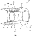
- FIG. 1 is a plan view of the upper part structure 10 of a vehicle body.
- the arrow FR indicates the forward direction of a vehicle; the arrow LH the leftward direction; and the arrow UP the upward direction, or a direction approaching a viewer facing the drawing.
- the directions indicated by the arrows are similarly applied to the subsequent drawings.
- the directions, such as, front, rear, right, left, up, and down, mentioned in the following description relate to the vehicle unless otherwise stated.
- the front-rear direction is referred to as a longitudinal direction while the right-left direction is referred to as a lateral direction.
- a side closer to the center line of the vehicle in the lateral direction is referred to as an inner side in the vehicle width direction, and a side farther from the center line is referred to as an outer side in the vehicle width direction.
- the side facing the vehicle cabin is referred to as an indoor side while a side opposite to the indoor side of the vehicle is referred to as an outdoor side.
- the upper part structure 10 includes a left side member 12L and a right side member 12R respectively constituting the left and right lateral surfaces of the vehicle body.
- the left side member 12L and the right side member 12R will be hereinafter simply referred to as side members 12 with “L” and “R” omitted when distinction is unnecessary. Left and right members making a pair will also be referred to with “L” and “R” omitted when distinction is unnecessary.
- the left side member 12L includes a left roof side rail 20L supported by a left front pillar 14L, a left center pillar 16L, and a left rear pillar 18L extending in the longitudinal direction on the upper edge of the left side member 12L.
- the right side member 12R includes a right roof side rail 20R supported by a right front pillar 14R, a right center pillar 16R, and a right rear pillar 18R, and extends in the longitudinal direction on the upper edge of the right side member 12R.
- the upper part structure 10 further includes a roof panel 22 extending between the left and right roof side rails 20L, 20R.
- the roof panel 22 is attached to the roof side rails 20 via the respective left and right lateral edges of the roof panel 22 through spot welding, for example.
- the roof panel 22 has a substantially rectangular roof opening 24 that is long in the lateral direction and formed in the front-half portion of the roof panel 22.
- the roof opening 24 is formed above the front seats such that the left and right lateral edges of the roof opening 24 extend in the longitudinal direction near the respective lateral edges of the roof panel 22.
- the roof opening 24 is an opening of a sunroof.
- a finished vehicle has a cover (not illustrated) removably attached to or to open and close the roof opening 24.
- a substantially rectangular roof opening reinforcement 26 (see FIGs. 2 and 4 ) is disposed on the lower surface of the roof panel 22, that is, the surface on the side in FIG. 1 farther from a viewer facing the drawing.
- the roof opening reinforcement 26 is disposed along the
- FIG. 2 illustrates the upper part structure 10 without the roof panel 22.
- a plurality of roof cross reinforcements 28 are disposed extending between the left and right roof side rails 20.
- the roof opening reinforcement 26 is disposed corresponding to the roof opening 24, as described above.
- the roof opening reinforcement 26 is a substantially rectangular frame, and has extended reinforcements 30L, 30R attached thereto on its respective left and right rear corners through spot welding, for example.
- the extended reinforcement 30 is not directly attached to the roof side rail 20.
- FIG. 3 illustrates the upper part structure 10 illustrated in FIG. 2 without the roof opening reinforcement 26 and the extended reinforcement 30.
- a cross beam 32 is disposed below the rear side portion of the roof opening reinforcement 26 so as to extend in the lateral direction.
- the respective left and right ends of the cross beam 32 are attached to the respective left and right beam brackets 34L, 34R attached to the roof side rails 20.
- FIG. 4 is an exploded perspective view of the roof panel 22, the roof opening reinforcement 26, and the extended reinforcements 30.
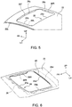
- FIG. 5 is a perspective view of the roof panel 22 around the roof opening 24 viewed from obliquely behind.
- the roof panel 22 is made by press-forming a steel plate into a predetermined shape.
- the main surface 22a of the roof panel 22 constitutes the outer surface of a finished vehicle.
- the roof panel 22 has a roof lateral edge flange 22b formed on each of its left and right lateral edges so as to be positioned lower than the main surface 22a.
- the roof panel 22 is attached to the roof side rails 20 through spot welding, for example, via the roof lateral edge flanges 22b.
- the roof panel 22 has a roof opening front edge flange 36F, a roof opening left lateral edge flange 36L, and a roof opening right lateral edge flange 36R formed along, and suspending from, the front edge 24a and the left and right lateral edges 24b, 24c, respectively, of the roof opening 24.
- These flanges 36F, 36L, 36R will be collectively referred to as roof opening edge flanges 36.
- the roof opening reinforcement 26 is made by press-forming a steel plate into a predetermined shape.
- the roof opening reinforcement 26 serves to impart strength and rigidity, and is thus made using a thicker steel plate than that which is used to form the roof panel 22, for which ease of press working should be considered.
- the roof opening reinforcement 26 includes a front side portion 26a, a left side portion 26b, a right side portion 26c, and a rear side portion 26d, that respectively extend along the front edge 24a, the left edge 24b, the right edge 24c, and the rear edge 24d of the roof opening 24 when the roof opening reinforcement 26 is assembled in the roof panel 22.
- Roof opening reinforcement flanges 38 are formed along and respectively suspend from the front side portion 26a, the left side portion 26b, and the right side portion 26c. Only the right side flange 38R of the right side portion 26c is illustrated in FIG. 4 .
- FIG. 6 illustrates the roof panel 22 with the roof opening reinforcement 26.
- the roof opening reinforcement flange 38 is positioned adjacent to and on the outer side of its corresponding roof opening edge flange 36. These flanges are attached to each other through spot welding, for example.
- the lower surface of the roof panel 22 is adhered to the upper surface of the rear side portion 26d of the roof opening reinforcement with adhesive agent along the rear edge 24d of the roof opening in an adhering area 40 indicated by the double diagonal lines in FIG. 6 .
- the frame-shaped roof opening reinforcement 26 is attached on the area around the periphery of the roof opening 24 of the roof panel 22 to reinforce the area for enhanced rigidity of the area.
- the rear side portion 26d of the roof opening reinforcement extends in the lateral direction along the rear edge 24d of the roof opening 24 to function as an opening rear edge reinforcement attached to the roof panel 22.
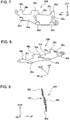
- FIGs. 7 to 9 illustrate the right-side extended reinforcement 30R.
- FIG. 7 is a plan view of the right-side extended reinforcement 30R
- FIG. 8 is a perspective view
- FIG. 9 illustrates the right-side extended reinforcement 30R viewed from the front.
- the left-side extended reinforcement 30L which has a symmetrical structure to that of the illustrated right-side extended reinforcement 30R, is not described here.
- the arrow OUT in the drawing indicates the outward direction in the vehicle lateral direction, and similarly applies to the subsequent drawings.
- the extended reinforcement 30 is made by press-forming a steel plate into a predetermined shape.
- the extended reinforcement 30 imparts strength and rigidity, and is thus made using a steel plate thicker than that which is used to form the roof panel 22 and as thick as that which is used to form the roof opening reinforcement 26.
- the extended reinforcement 30 includes a main portion 30a and three extended portions 30b extending outward from the main portion 30a in the vehicle lateral direction. Notches 30c are formed between these three extended portions 30b.
- the notch 30c is formed extending inward in the vehicle lateral direction from the outer end edge of the extended reinforcement 30 in the vehicle lateral direction, that is, an end edge defined by the tip end edge of the extended portion 30b.
- the extended portion 30b is attached to the roof lateral edge flange 22b of the roof panel 22 through spot welding, for example.
- the main portion 30a of the extended reinforcement has an attachment portion 30d formed on its inner side edge in the vehicle lateral direction.
- the attachment portion 30d is to be attached to the roof opening reinforcement 26 through spot welding, for example.
- the main portion 30a further has a ridge 30e protruding upward and extending in the substantially lateral direction. The ridge 30e enhances rigidity of the extended reinforcement 30 in the lateral direction.
- the distortion will cause large deformation in an area around, in particular, near the corners of, the roof opening 24 of the roof panel 22.
- the extended reinforcement 30 is assembled in the upper part structure 10 to enhance rigidity in areas near the above-mentioned corners to thereby prevent deformation of the roof panel 22. This structure near the corners will now be described below in detail.
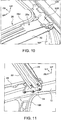
- FIG. 10 is a perspective view of an area near the right rear corner of the roof opening 24 viewed from outside the vehicle cabin.
- FIG. 11 illustrates the same area viewed from inside the vehicle cabin.
- the roof panel 22 is not illustrated in FIGs. 10 and 11 .
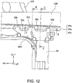
- FIG. 12 is a plan view of an area near the right rear corner of the roof opening 24.
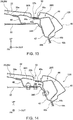
- FIG. 13 is a cross sectional view along the line B-B in FIG. 12 , or a cross section passing through the extended portion 30b of the extended reinforcement.
- FIG. 14 is a cross sectional view along the line C-C in FIG. 12 , or a cross section passing through the notch 30c of the extended reinforcement.
- the structure near the left rear corner of the roof opening 24, which is symmetrical to that around the right rear corner illustrated in FIGs. 10 to 14 is not described here.
- the roof side rail 20 includes an inner rail member 42 disposed on the indoor side and an outer rail member 44 disposed on the outdoor side.
- Each of the inner rail member 42 and the outer rail member 44 is made by press-forming a steel plate into a predetermined shape.
- the inner rail member 42 and the outer rail member 44 respectively have upper edge flanges 42a, 44a along the respective upper edges and lower edge flanges 42b, 44b along the respective lower edges.
- the upper edge flanges 42a, 44a are attached to each other through spot welding, for example, and the lower edge flanges 42b, 44b are attached to each other through spot welding, for example, whereby the closed cross section of the roof side rail 20 is defined.
- a lateral surface outer panel 46 is disposed on the outdoor side of the outer rail member 44, constituting the outermost surface of a finished vehicle.
- the lateral surface outer panel 46 is made by press-forming a steel plate into a predetermined shape. Specifically, a steel plate thinner than that which is used to form the inner rail member 42 and the outer rail member 44 is used to form the lateral surface outer panel 46 for ease of molding.
- the lateral surface outer panel 46 has an upper edge flange 46a along its upper edge, and the upper edge flange 46a is attached to the upper edge flanges 42a, 44a of the respective inner and outer rail members through spot welding, for example.
- the lateral surface outer panel 46 has a lower edge flange 46b along its lower edge, and the lower edge flange 46b is attached to the lower edge flanges 42b, 44b of the respective inner and outer rail members through spot welding, for example.
- a beam bracket 34 is attached with attachment pieces, such as a bolt and a nut, at a position on the indoor side near a position where the inner rail member 42 is attached to the center pillar 16.
- the beam bracket 34 can be made by press-forming a steel plate into a predetermined shape.
- the beam bracket 34 is also attached to the cross beam 32 with attachment pieces, such as a bolt and a nut.
- the cross beam 32 can be made by press-forming a steel plate into a predetermined shape.
- the beam bracket 34 and the cross beam 32, which impart strength, are made using a steel plate thicker than that which is used to make the outer surface of the vehicle body, such as the lateral surface outer panel 46.
- the roof opening reinforcement 26 is attached to a roof bracket 48 through spot welding, for example.
- the roof bracket 48 is attached to the beam bracket 34 with attachment pieces, such as a bolt and a nut. Specifically, the bolt and nut that are used to attach the cross beam 32 to the beam bracket 34 can be used to attach the roof bracket 48.
- the roof bracket 48 which imparts strength, is made using a steel plate thicker than that which is used to form the roof panel 22 and substantially as thick as that which is used to form the roof opening reinforcement 26.
- the roof bracket 48 is omissible if required strength can be achieved without the roof bracket 48.
- the respective flanges 22b, 46a, 44a, 42a of the roof panel 22, the lateral surface outer panel 46, the outer rail member 44, the inner rail member 42, and the extended portion 30b of the extended reinforcement are disposed stacked on one another, thereby constituting the bottom portion of the groove 50 extending in the longitudinal direction along the right/left lateral edge of the roof.
- a mold (not illustrated) is buried in and along the groove 50 of a finished vehicle such that the upper surface of the mold connects the outer surfaces of the roof panel 22 and of the lateral surface outer panel 46 substantially without a step.
- the upper surface 26e of the rear side portion 26d of the roof opening reinforcement 26 extends in the lateral direction along, while being spaced apart from, the lower surface of the roof panel 22.
- the upper surface 26e will be hereinafter referred to as a roof panel opposed surface 26e.
- the extended reinforcement 30 extends outward in the vehicle lateral direction beyond the lateral edge of the roof opening reinforcement 26 as if forming an extension of the roof panel opposed surface 26e.
- the extended portion 30b of the extended reinforcement extends to the roof lateral edge flange 22b and is attached to the roof lateral edge flange 22b through spot welding, for example.
- the extended reinforcement 30 does not extend to the upper edge flange 44a, for example, of the outer rail member at the positions corresponding to the notches 30c.
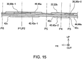
- FIG. 15 is a cross sectional view along the line E-E in FIG. 12 , with respective thicknesses illustrated exaggeratedly.
- the three extended portions 30b of the extended reinforcement 30 are aligned separate from one another, and are thus illustrated discretely in FIG. 15 .
- the one positioned ahead is identified as 30b-1, while the one behind as 30b-2.
- the upper edge flange 42a of the inner rail member has notches 42c, and is thus illustrated as separate pieces in FIG. 15 , similarly to the extended reinforcement 30.
- the one piece of the upper edge flange 42a positioned ahead is identified as 42a-1, while the one behind is identified as 42a-2.
- the extended portion 30b-1 of the extended reinforcement, the upper edge flange 42a-1 of the inner rail member, the roof lateral edge flange 22b of the roof panel, the upper edge flange 46a of the lateral surface outer panel, and the upper edge flange 44a of the outer rail member are disposed stacked on one another at the positions P1, P2 illustrated.
- the extended portion 30b-2 of the extended reinforcement is disposed stacked on the roof lateral edge flange 22b of the roof panel, the upper edge flange 46a of the lateral surface outer panel, and the upper edge flange 44a of the outer rail member at the position P3 illustrated.
- the upper edge flange 42a-2 of the inner rail member is disposed stacked on the roof lateral edge flange 22b of the roof panel, the upper edge flange 46a of the lateral surface outer panel, and the upper edge flange 44a of the outer rail member at the position P4 illustrated.
- the notch 30c see FIGs. 8 , 12
- the upper edge flange 46a of the lateral surface outer panel, and the upper edge flange 44a of the outer rail member are disposed stacked on one another.
- the roof panel 22 is attached to the extended reinforcement 30 through spot welding, for example, at the positions P1 and P3.
- the positions P1 and P3 are first positions where the roof panel 22 is attached to the extended reinforcement 30.
- the lateral surface outer panel 46, the outer rail member 44, and the inner rail member 42 are attached to one another through spot welding, for example, at the positions P2 and P4.
- the positions P2 and P4 are second positions where the lateral surface outer panel 46, the outer rail member 44, and the inner rail member 42 are attached to one another.
- the roof panel 22, the lateral surface outer panel 46, and the outer rail member 44 are attached to one another at a position P5 and a position P6 through spot welding, for example.
- the positions P5 and P6 are third positions where the roof panel 22, the lateral surface outer panel 46, and the outer rail member 44 are attached to one another. Although the positions P1 and P2 are defined at the same position, the attachment of the roof panel 22 and the extended reinforcement 30 is independent of the attachment of the lateral surface outer panel 46, the outer rail member 44, and the inner rail member 42. At the position P3, the lateral surface outer panel 46 is not attached to the outer rail member 44, and the lateral surface outer panel 46 and the outer rail member 44 are not attached to the roof panel 22 and the extended reinforcement 30, either. At the position P4, the roof panel 22 is not attached to the lateral surface outer panel 46, the outer rail member 44, and the inner rail member 42.
- the extended reinforcement 30 is attached to the roof panel via the three extended portions 30b, but not directly attached to the lateral surface outer panel 46, the outer rail member 44, and the inner rail member 42. Further, the roof panel 22, the lateral surface outer panel 46, and the outer rail member 44 are attached to one another at respective positions corresponding to two notches 30c of the extended reinforcement 30.
- the first positions (P1, P3) and the third positions (P6, P5) are alternately aligned.
- the second positions (P2, P4) and the third positions (P6, P5) are alternately aligned.
- a first position (either P1 or P3) and a second position (either P2 or P4) that are located close to each other make a set the position P1 and the position P2 make a first set
- the position P3 and the position P4 make a second set.
- These attached positions and the attached position sets are aligned in FIG. 15 in the order of the position P6, the first position set (the positions P1 and P2), the position P5, and the second position set (the positions P3 and P4).
- This manner of alignment can prevent the interval between the attached points of the roof panel 22 and the side member 12 and the interval between the attached points of the roof panel 22 and the extended reinforcement 30 from becoming longer.
- the first position (either P1 or P3) and the second position (either P2 or P4) that make a set can be defined at the same position in at least one set.
- the positions P1 and P2, making the first set are defined at the same position, and the positions P3 and P4, making the second set, are not.
- the first position and the second position in every set can be defined at the same position. Defining the first and second positions at the same position can make a shorter interval between attached points.
- notches 30c, 42c on the end edges of the extended reinforcement 30 and the inner rail member 42, respectively, allows alignment of the attached points at the same position in the longitudinal direction. This allows the attached points to be accommodated in the groove 50.
- the upper part structure 10 reinforces a peripheral area of the rear corners of the roof opening of the roof panel 22 with the extended reinforcement 30.
- the reinforcement can prevent deformation of the area due to deformation of the vehicle body. This can prevent occurrence of cracks at and around the attached point.
Landscapes
- Engineering & Computer Science (AREA)
- Mechanical Engineering (AREA)
- Chemical & Material Sciences (AREA)
- Combustion & Propulsion (AREA)
- Transportation (AREA)
- Body Structure For Vehicles (AREA)
Abstract
Description
- This application claims priority to Japanese Patent Application No.
2018-009387 filed on January 24, 2018 - The present disclosure relates to the upper part structure of a vehicle body having a roof panel with an opening, such as a vehicle having a sunroof.
- Vehicles having roofs, called sunroofs, for partial opening and closing have been known. Such a vehicle with a sunroof has a roof panel with an opening and a cover for opening and closing the opening.
- Patent Literature 1 discloses the upper part structure (40) of a vehicle body of a vehicle (10) having a sunroof. The roof of the vehicle (10) includes a roof panel (14) having an opening (16) and a sliding glass (34) that slides to open and close the opening (16). In general, a roof panel is attached to roof side rails extending along the respective left and right side edges of the roof. Note that the reference numerals in the parentheses above are those given in Patent Literature 1 and are not related to those referred to in the following description of the embodiment of this disclosure.
- PATENT LITERATURE 1:
JP2016-153291A - In the case of a roof panel having an opening, deformation of a vehicle leads to distortion of the roof panel concentrated around the periphery of the opening, which results in large deformation in the area. A rectangular opening, for example, is subjected to large deformation in particular near the corners of the opening. Deformation around the periphery of the opening causes cracks in and around an area where the roof panel is attached to the roof side rails. This may deteriorate reliable attachment.
- The present disclosure aims to prevent occurrence of cracks at and around an attachment portion of a roof panel and roof side rails near the corners of a rectangular roof opening.
- The upper part structure of a vehicle body according to the present disclosure includes a pair of roof side rails extending in the longitudinal direction of a vehicle in respective upper left and right lateral portions of the vehicle, and a roof panel disposed extending between, and attached to, the pair of roof side rails to constitute a roof of the vehicle. The roof panel has a rectangular roof opening, and is attached, on its lower surface, to an opening rear edge reinforcement extending along the rear edge of the roof opening. The opening rear edge reinforcement has a roof panel opposed surface extending along the lower surface of the roof panel. The upper part structure further includes a pair of extended reinforcements extending from the roof panel opposed surface of the opening rear edge reinforcement toward the respective left and right lateral end edges of the roof panel, as if forming an extension of the roof panel opposed surface. The pair of extended reinforcement are disposed corresponding to the respective left and right rear corners of the roof opening. The pair of extended reinforcement are attached to the roof panel near where the roof panel is attached to the roof side rails.
- The provision of the extended reinforcements corresponding to the left and right rear corners of the roof opening enhances rigidity of the roof in the areas, and can thus prevent displacement of the roof panel.
- The upper part structure of a vehicle body mentioned above may further include a lateral surface outer panel covering the outdoor-side surface of the roof side rail. The roof side rail may include an outer rail member disposed on the outdoor side and an inner rail member disposed on the indoor side, the outer rail member and the inner rail member together defining a closed cross sectional structure. The roof panel may be attached to the extended reinforcement at first positions in the longitudinal direction of the vehicle. The lateral surface outer panel, the outer rail member, and the inner rail member may be attached to one another at second positions in the longitudinal direction of the vehicle. The roof panel, the lateral surface outer panel, and the outer rail member may be attached to one another at third positions in the longitudinal direction of the vehicle, the third positions being different from the first positions and the second positions.
- Separation of the attachment positions can prevent the stacking thickness of the members attached in one attachment from becoming thicker.
- The first positions and the third positions may be alternately aligned. The second positions and the third positions may be alternately aligned. This can enhance reliability of attachment between members.
- The first position may be defined at the same position as the second position in at least some attachments. This can reduce a space needed for attachment.
- The extended reinforcement may be disposed stacked on the lateral surface outer panel, the outer rail member, and the inner rail member at the first position. The extended reinforcement may have a notch formed at the third position, the notch extending inward from the outer end edge of the extended reinforcement in the lateral direction while avoiding where the roof panel, the lateral surface outer panel, and the outer rail member are attached to one another.
- The provision of the notch to the extended reinforcement enables alignment of the attached points in the longitudinal direction of the vehicle. This can reduce a space necessary for attachment in the lateral direction.
- The opening rear edge reinforcement may be a part of a roof opening reinforcement formed along the peripheral edge of the roof opening and attached to the roof panel. This can reinforce the peripheral edge of the opening.
- The extended reinforcement prevents displacement of a part near the corners of the roof opening of a roof panel, and can thus prevent occurrence of cracks at and around attachment portions of the roof panel and the roof side rails near the corners.
- Embodiment(s) of the present disclosure will be described based on the following figures, wherein:
-
FIG. 1 is a plan view of an upper part structure of a vehicle body according to this embodiment; -
FIG. 2 is a plan view of an upper part structure of a vehicle body without a roof panel; -
FIG. 3 is a plan view of an upper part structure of a vehicle body without a roof panel, a roof opening reinforcement, and an extended reinforcement; -
FIG. 4 is a perspective view of a roof panel, a roof opening reinforcement, and an extended reinforcement; -
FIG. 5 is a perspective view of the structure of an area around the periphery of a roof opening; -
FIG. 6 is a perspective view of the structure of an area around the periphery of a roof opening with a roof opening reinforcement; -
FIG. 7 is a plan view of an extended reinforcement; -
FIG. 8 is a perspective view of an extended reinforcement; -
FIG. 9 illustrates an extended reinforcement viewed from the front; -
FIG. 10 illustrates the structure of an area near the right rear corner of the roof opening viewed from outside the vehicle cabin; -
FIG. 11 illustrates the structure of an area near the right rear corner of the roof opening viewed from inside the vehicle cabin; -
FIG. 12 is a plan view of the structure of an area near the right rear corner of the roof opening; -
FIG. 13 is a cross sectional view along the line B-B inFIG. 11 ; -
FIG. 14 is a cross sectional view along the line C-C inFIG. 11 ; and -
FIG. 15 is a cross sectional view along the line E-E inFIG. 11 . - An embodiment of the present disclosure will now be described with reference to the accompanying drawings.
FIG. 1 is a plan view of theupper part structure 10 of a vehicle body. The arrow FR indicates the forward direction of a vehicle; the arrow LH the leftward direction; and the arrow UP the upward direction, or a direction approaching a viewer facing the drawing. The directions indicated by the arrows are similarly applied to the subsequent drawings. The directions, such as, front, rear, right, left, up, and down, mentioned in the following description relate to the vehicle unless otherwise stated. The front-rear direction is referred to as a longitudinal direction while the right-left direction is referred to as a lateral direction. A side closer to the center line of the vehicle in the lateral direction is referred to as an inner side in the vehicle width direction, and a side farther from the center line is referred to as an outer side in the vehicle width direction. For sides of a member or a structural component that defines a vehicle cabin, the side facing the vehicle cabin is referred to as an indoor side while a side opposite to the indoor side of the vehicle is referred to as an outdoor side. - The
upper part structure 10 includes aleft side member 12L and aright side member 12R respectively constituting the left and right lateral surfaces of the vehicle body. Theleft side member 12L and theright side member 12R will be hereinafter simply referred to asside members 12 with "L" and "R" omitted when distinction is unnecessary. Left and right members making a pair will also be referred to with "L" and "R" omitted when distinction is unnecessary. Theleft side member 12L includes a leftroof side rail 20L supported by a leftfront pillar 14L, aleft center pillar 16L, and a leftrear pillar 18L extending in the longitudinal direction on the upper edge of theleft side member 12L. Similarly, theright side member 12R includes a rightroof side rail 20R supported by a rightfront pillar 14R, aright center pillar 16R, and a rightrear pillar 18R, and extends in the longitudinal direction on the upper edge of theright side member 12R. - The
upper part structure 10 further includes aroof panel 22 extending between the left and right roof side rails 20L, 20R. Theroof panel 22 is attached to the roof side rails 20 via the respective left and right lateral edges of theroof panel 22 through spot welding, for example. Theroof panel 22 has a substantially rectangular roof opening 24 that is long in the lateral direction and formed in the front-half portion of theroof panel 22. Theroof opening 24 is formed above the front seats such that the left and right lateral edges of theroof opening 24 extend in the longitudinal direction near the respective lateral edges of theroof panel 22. Theroof opening 24 is an opening of a sunroof. A finished vehicle has a cover (not illustrated) removably attached to or to open and close theroof opening 24. A substantially rectangular roof opening reinforcement 26 (seeFIGs. 2 and4 ) is disposed on the lower surface of theroof panel 22, that is, the surface on the side inFIG. 1 farther from a viewer facing the drawing. Theroof opening reinforcement 26 is disposed along the peripheral edge of theroof opening 24. -
FIG. 2 illustrates theupper part structure 10 without theroof panel 22. A plurality ofroof cross reinforcements 28 are disposed extending between the left and right roof side rails 20. Theroof opening reinforcement 26 is disposed corresponding to theroof opening 24, as described above. Theroof opening reinforcement 26 is a substantially rectangular frame, and has extendedreinforcements -
FIG. 3 illustrates theupper part structure 10 illustrated inFIG. 2 without theroof opening reinforcement 26 and the extended reinforcement 30. Across beam 32 is disposed below the rear side portion of theroof opening reinforcement 26 so as to extend in the lateral direction. The respective left and right ends of thecross beam 32 are attached to the respective left andright beam brackets -
FIG. 4 is an exploded perspective view of theroof panel 22, theroof opening reinforcement 26, and the extended reinforcements 30.FIG. 5 is a perspective view of theroof panel 22 around the roof opening 24 viewed from obliquely behind. Theroof panel 22 is made by press-forming a steel plate into a predetermined shape. Themain surface 22a of theroof panel 22 constitutes the outer surface of a finished vehicle. Theroof panel 22 has a rooflateral edge flange 22b formed on each of its left and right lateral edges so as to be positioned lower than themain surface 22a. Theroof panel 22 is attached to the roof side rails 20 through spot welding, for example, via the rooflateral edge flanges 22b. Theroof panel 22 has a roof openingfront edge flange 36F, a roof opening leftlateral edge flange 36L, and a roof opening rightlateral edge flange 36R formed along, and suspending from, thefront edge 24a and the left and rightlateral edges roof opening 24. Theseflanges - The
roof opening reinforcement 26 is made by press-forming a steel plate into a predetermined shape. Theroof opening reinforcement 26 serves to impart strength and rigidity, and is thus made using a thicker steel plate than that which is used to form theroof panel 22, for which ease of press working should be considered. Theroof opening reinforcement 26 includes afront side portion 26a, aleft side portion 26b, aright side portion 26c, and arear side portion 26d, that respectively extend along thefront edge 24a, theleft edge 24b, theright edge 24c, and therear edge 24d of theroof opening 24 when theroof opening reinforcement 26 is assembled in theroof panel 22. Roofopening reinforcement flanges 38 are formed along and respectively suspend from thefront side portion 26a, theleft side portion 26b, and theright side portion 26c. Only theright side flange 38R of theright side portion 26c is illustrated inFIG. 4 . -
FIG. 6 illustrates theroof panel 22 with theroof opening reinforcement 26. The roof openingreinforcement flange 38 is positioned adjacent to and on the outer side of its corresponding roof opening edge flange 36. These flanges are attached to each other through spot welding, for example. The lower surface of theroof panel 22 is adhered to the upper surface of therear side portion 26d of the roof opening reinforcement with adhesive agent along therear edge 24d of the roof opening in an adheringarea 40 indicated by the double diagonal lines inFIG. 6 . The frame-shapedroof opening reinforcement 26 is attached on the area around the periphery of the roof opening 24 of theroof panel 22 to reinforce the area for enhanced rigidity of the area. Therear side portion 26d of the roof opening reinforcement extends in the lateral direction along therear edge 24d of the roof opening 24 to function as an opening rear edge reinforcement attached to theroof panel 22. -
FIGs. 7 to 9 illustrate the right-sideextended reinforcement 30R. Specifically,FIG. 7 is a plan view of the right-sideextended reinforcement 30R;FIG. 8 is a perspective view; andFIG. 9 illustrates the right-sideextended reinforcement 30R viewed from the front. The left-sideextended reinforcement 30L, which has a symmetrical structure to that of the illustrated right-sideextended reinforcement 30R, is not described here. The arrow OUT in the drawing indicates the outward direction in the vehicle lateral direction, and similarly applies to the subsequent drawings. The extended reinforcement 30 is made by press-forming a steel plate into a predetermined shape. The extended reinforcement 30 imparts strength and rigidity, and is thus made using a steel plate thicker than that which is used to form theroof panel 22 and as thick as that which is used to form theroof opening reinforcement 26. The extended reinforcement 30 includes amain portion 30a and threeextended portions 30b extending outward from themain portion 30a in the vehicle lateral direction.Notches 30c are formed between these threeextended portions 30b. Thenotch 30c is formed extending inward in the vehicle lateral direction from the outer end edge of the extended reinforcement 30 in the vehicle lateral direction, that is, an end edge defined by the tip end edge of theextended portion 30b. Theextended portion 30b is attached to the rooflateral edge flange 22b of theroof panel 22 through spot welding, for example. Themain portion 30a of the extended reinforcement has anattachment portion 30d formed on its inner side edge in the vehicle lateral direction. Theattachment portion 30d is to be attached to theroof opening reinforcement 26 through spot welding, for example. Themain portion 30a further has aridge 30e protruding upward and extending in the substantially lateral direction. Theridge 30e enhances rigidity of the extended reinforcement 30 in the lateral direction. - If a vehicle body distorts, the distortion will cause large deformation in an area around, in particular, near the corners of, the roof opening 24 of the
roof panel 22. For example, in the case where the front axle and the rear axle tilt in mutually opposite directions when viewed from the front of the vehicle due to an input from a road surface, the vehicle body will twist, causing large deformation around the left and right rear corners of theroof opening 24. In this embodiment, the extended reinforcement 30 is assembled in theupper part structure 10 to enhance rigidity in areas near the above-mentioned corners to thereby prevent deformation of theroof panel 22. This structure near the corners will now be described below in detail. -
FIG. 10 is a perspective view of an area near the right rear corner of the roof opening 24 viewed from outside the vehicle cabin.FIG. 11 illustrates the same area viewed from inside the vehicle cabin. Theroof panel 22 is not illustrated inFIGs. 10 and 11 .FIG. 12 is a plan view of an area near the right rear corner of theroof opening 24.FIG. 13 is a cross sectional view along the line B-B inFIG. 12 , or a cross section passing through theextended portion 30b of the extended reinforcement.FIG. 14 is a cross sectional view along the line C-C inFIG. 12 , or a cross section passing through thenotch 30c of the extended reinforcement. The structure near the left rear corner of theroof opening 24, which is symmetrical to that around the right rear corner illustrated inFIGs. 10 to 14 , is not described here. - As illustrated in
FIGs. 13 and 14 , the roof side rail 20 includes aninner rail member 42 disposed on the indoor side and anouter rail member 44 disposed on the outdoor side. Each of theinner rail member 42 and theouter rail member 44 is made by press-forming a steel plate into a predetermined shape. Theinner rail member 42 and theouter rail member 44 respectively haveupper edge flanges lower edge flanges upper edge flanges lower edge flanges outer panel 46 is disposed on the outdoor side of theouter rail member 44, constituting the outermost surface of a finished vehicle. The lateral surfaceouter panel 46 is made by press-forming a steel plate into a predetermined shape. Specifically, a steel plate thinner than that which is used to form theinner rail member 42 and theouter rail member 44 is used to form the lateral surfaceouter panel 46 for ease of molding. The lateral surfaceouter panel 46 has anupper edge flange 46a along its upper edge, and theupper edge flange 46a is attached to theupper edge flanges outer panel 46 has alower edge flange 46b along its lower edge, and thelower edge flange 46b is attached to thelower edge flanges - A
beam bracket 34 is attached with attachment pieces, such as a bolt and a nut, at a position on the indoor side near a position where theinner rail member 42 is attached to the center pillar 16. Thebeam bracket 34 can be made by press-forming a steel plate into a predetermined shape. Thebeam bracket 34 is also attached to thecross beam 32 with attachment pieces, such as a bolt and a nut. Thecross beam 32 can be made by press-forming a steel plate into a predetermined shape. Thebeam bracket 34 and thecross beam 32, which impart strength, are made using a steel plate thicker than that which is used to make the outer surface of the vehicle body, such as the lateral surfaceouter panel 46. - The
roof opening reinforcement 26 is attached to aroof bracket 48 through spot welding, for example. Theroof bracket 48 is attached to thebeam bracket 34 with attachment pieces, such as a bolt and a nut. Specifically, the bolt and nut that are used to attach thecross beam 32 to thebeam bracket 34 can be used to attach theroof bracket 48. Theroof bracket 48, which imparts strength, is made using a steel plate thicker than that which is used to form theroof panel 22 and substantially as thick as that which is used to form theroof opening reinforcement 26. Theroof bracket 48 is omissible if required strength can be achieved without theroof bracket 48. - The
respective flanges roof panel 22, the lateral surfaceouter panel 46, theouter rail member 44, theinner rail member 42, and theextended portion 30b of the extended reinforcement are disposed stacked on one another, thereby constituting the bottom portion of thegroove 50 extending in the longitudinal direction along the right/left lateral edge of the roof. A mold (not illustrated) is buried in and along thegroove 50 of a finished vehicle such that the upper surface of the mold connects the outer surfaces of theroof panel 22 and of the lateral surfaceouter panel 46 substantially without a step. - The
upper surface 26e of therear side portion 26d of theroof opening reinforcement 26 extends in the lateral direction along, while being spaced apart from, the lower surface of theroof panel 22. Theupper surface 26e will be hereinafter referred to as a roof panel opposedsurface 26e. The extended reinforcement 30 extends outward in the vehicle lateral direction beyond the lateral edge of theroof opening reinforcement 26 as if forming an extension of the roof panel opposedsurface 26e. In particular, theextended portion 30b of the extended reinforcement extends to the rooflateral edge flange 22b and is attached to the rooflateral edge flange 22b through spot welding, for example. As clearly illustrated inFIG. 12 , the extended reinforcement 30 does not extend to theupper edge flange 44a, for example, of the outer rail member at the positions corresponding to thenotches 30c. -
FIG. 15 is a cross sectional view along the line E-E inFIG. 12 , with respective thicknesses illustrated exaggeratedly. The threeextended portions 30b of the extended reinforcement 30 are aligned separate from one another, and are thus illustrated discretely inFIG. 15 . For distinction, of the twoextended portion 30b illustrated, the one positioned ahead is identified as 30b-1, while the one behind as 30b-2. Theupper edge flange 42a of the inner rail member hasnotches 42c, and is thus illustrated as separate pieces inFIG. 15 , similarly to the extended reinforcement 30. The one piece of theupper edge flange 42a positioned ahead is identified as 42a-1, while the one behind is identified as 42a-2. - The
extended portion 30b-1 of the extended reinforcement, theupper edge flange 42a-1 of the inner rail member, the rooflateral edge flange 22b of the roof panel, theupper edge flange 46a of the lateral surface outer panel, and theupper edge flange 44a of the outer rail member are disposed stacked on one another at the positions P1, P2 illustrated. Theextended portion 30b-2 of the extended reinforcement is disposed stacked on the rooflateral edge flange 22b of the roof panel, theupper edge flange 46a of the lateral surface outer panel, and theupper edge flange 44a of the outer rail member at the position P3 illustrated. Theupper edge flange 42a-2 of the inner rail member is disposed stacked on the rooflateral edge flange 22b of the roof panel, theupper edge flange 46a of the lateral surface outer panel, and theupper edge flange 44a of the outer rail member at the position P4 illustrated. At the position P5, where thenotch 30c (seeFIGs. 8 ,12 ) of the extended reinforcement is aligned with thenotch 42c of the inner rail member, only the rooflateral edge flange 22b of the roof panel, theupper edge flange 46a of the lateral surface outer panel, and theupper edge flange 44a of the outer rail member are disposed stacked on one another. - The
roof panel 22 is attached to the extended reinforcement 30 through spot welding, for example, at the positions P1 and P3. The positions P1 and P3 are first positions where theroof panel 22 is attached to the extended reinforcement 30. The lateral surfaceouter panel 46, theouter rail member 44, and theinner rail member 42 are attached to one another through spot welding, for example, at the positions P2 and P4. The positions P2 and P4 are second positions where the lateral surfaceouter panel 46, theouter rail member 44, and theinner rail member 42 are attached to one another. Theroof panel 22, the lateral surfaceouter panel 46, and theouter rail member 44 are attached to one another at a position P5 and a position P6 through spot welding, for example. The positions P5 and P6 are third positions where theroof panel 22, the lateral surfaceouter panel 46, and theouter rail member 44 are attached to one another. Although the positions P1 and P2 are defined at the same position, the attachment of theroof panel 22 and the extended reinforcement 30 is independent of the attachment of the lateral surfaceouter panel 46, theouter rail member 44, and theinner rail member 42. At the position P3, the lateral surfaceouter panel 46 is not attached to theouter rail member 44, and the lateral surfaceouter panel 46 and theouter rail member 44 are not attached to theroof panel 22 and the extended reinforcement 30, either. At the position P4, theroof panel 22 is not attached to the lateral surfaceouter panel 46, theouter rail member 44, and theinner rail member 42. - The extended reinforcement 30 is attached to the roof panel via the three
extended portions 30b, but not directly attached to the lateral surfaceouter panel 46, theouter rail member 44, and theinner rail member 42. Further, theroof panel 22, the lateral surfaceouter panel 46, and theouter rail member 44 are attached to one another at respective positions corresponding to twonotches 30c of the extended reinforcement 30. - According to the attachment in the above described manner, three out of five steel plates at most are attached to one another per one attachment. This can prevent the stacking thickness of an attachment portion from being thicker, which facilitates attachment. For example, a conventional spot-welder can be used for the attachment in this manner. Further, the relatively thick steel plates of the extended reinforcement 30, the
outer rail member 44, and theinner rail member 42 are not attached all together at the same time. This also contributes to reduction in the stacking thickness of an attachment portion. - The first positions (P1, P3) and the third positions (P6, P5) are alternately aligned. The second positions (P2, P4) and the third positions (P6, P5) are alternately aligned. Assuming that a first position (either P1 or P3) and a second position (either P2 or P4) that are located close to each other make a set, the position P1 and the position P2 make a first set, and the position P3 and the position P4 make a second set. These attached positions and the attached position sets are aligned in
FIG. 15 in the order of the position P6, the first position set (the positions P1 and P2), the position P5, and the second position set (the positions P3 and P4). This manner of alignment can prevent the interval between the attached points of theroof panel 22 and theside member 12 and the interval between the attached points of theroof panel 22 and the extended reinforcement 30 from becoming longer. - The first position (either P1 or P3) and the second position (either P2 or P4) that make a set can be defined at the same position in at least one set. In this embodiment, the positions P1 and P2, making the first set, are defined at the same position, and the positions P3 and P4, making the second set, are not. Alternatively, the first position and the second position in every set can be defined at the same position. Defining the first and second positions at the same position can make a shorter interval between attached points.
- The formation of the
notches inner rail member 42, respectively, allows alignment of the attached points at the same position in the longitudinal direction. This allows the attached points to be accommodated in thegroove 50. - The
upper part structure 10 reinforces a peripheral area of the rear corners of the roof opening of theroof panel 22 with the extended reinforcement 30. The reinforcement can prevent deformation of the area due to deformation of the vehicle body. This can prevent occurrence of cracks at and around the attached point. - Although a vehicle having a roof panel with an opening to be opened and closed with a cover has been described in the above, this is not an exclusive example, and the present disclosure can be applied to a vehicle having a roof where any different member, such as glass, is fixedly assembled in the opening on the roof panel.
Claims (6)
- An upper part structure (10) of a vehicle body, comprising:a pair of roof side rails (20R, 20L) extending in a longitudinal direction of a vehicle in respective upper left and right lateral portions of the vehicle;a roof panel (22) disposed extending between, and attached to, the pair of roof side rails (20R, 20L) to constitute a roof of the vehicle, the roof panel (22) having a rectangular roof opening (24); andan opening rear edge reinforcement (26d) extending in a lateral direction along a rear edge of the roof opening (24) and attached to the roof panel (22), the opening rear edge reinforcement (26d) having a roof panel opposed surface (26e) extending along a lower surface of the roof panel (22); anda pair of extended reinforcements (30R, 30L) disposed corresponding to respective left and right rear corners of the roof opening (24) so as to extend from the roof panel opposed surface (26e) of the opening rear edge reinforcement (26d) toward respective left and right lateral end edges of the roof panel (22) as if forming an extension of the roof panel opposed surface (26e), the pair of extended reinforcements being attached to the roof panel (22) near where the roof panel (22) is attached to the roof side rails (20R, 20L).
- The upper part structure (10) of a vehicle body according to claim 1, further comprising a lateral surface outer panel (46) covering an outdoor-side surface of the roof side rail (20R, 20L),
wherein
the roof side rail (20R, 20L) includes an outer rail member (44) disposed on an outdoor side and an inner rail member (42) disposed on an indoor side, the outer rail member (44) and the inner rail member (42) together defining a closed cross sectional structure,
the roof panel (22) is attached to the extended reinforcement (30R, 30L) at first positions (P1, P3) in the longitudinal direction of the vehicle,
the lateral surface outer panel (46), the outer rail member (44), and the inner rail member (42) are attached to one another at second positions (P2, P4) in the longitudinal direction of the vehicle, and
the roof panel (22), the lateral surface outer panel (46), and the outer rail member (44) are attached to one another at third positions (P5) in the longitudinal direction of the vehicle, the third positions (P5) being different from the first positions (P1, P3) and the second positions (P2, P4). - The upper part structure (10) of a vehicle body according to claim 2, wherein
the first positions (P1, P3) and the third positions (P5) are alternately aligned, and
the second positions (P2, P4) and the third positions (P5) are alternately aligned. - The upper part structure (10) of a vehicle body according to claim 2 or 3, wherein
assuming that one of the first positions (P1, P3) and one of the second positions (P2, P4), the ones being located close to each other, make a set so that a plurality of sets are resulted, in at least one set, the first position (P1) and the second position (P2) that make the set are defined at the same position in the longitudinal direction of the vehicle. - The upper part structure (10) of a vehicle body according to any one of claims 2 to 4, wherein
the extended reinforcement (30R, 30L) is disposed stacked on the lateral surface outer panel (46), the outer rail member (44), and the inner rail member (42) at the first positions (P1, P3), and
the extended reinforcement (30R, 30L) has a notch (42c) formed at each of the third positions (P5), the notch (42c) extending inward from an outer end edge of the extended reinforcement (30R, 30L) in the lateral direction while avoiding where the roof panel (22), the lateral surface outer panel (46), and the outer rail member (44) are attached to one another. - The upper part structure (10) of a vehicle body according to any one of claims 1 to 5, wherein the opening rear edge reinforcement (26d) is a part of a roof opening reinforcement (30R, 30L) formed along a peripheral edge of the roof opening (24) and attached to the roof panel (22).
Applications Claiming Priority (1)
| Application Number | Priority Date | Filing Date | Title |
|---|---|---|---|
| JP2018009387A JP6916122B2 (en) | 2018-01-24 | 2018-01-24 | Vehicle upper body structure |
Publications (2)
| Publication Number | Publication Date |
|---|---|
| EP3521144A1 true EP3521144A1 (en) | 2019-08-07 |
| EP3521144B1 EP3521144B1 (en) | 2021-02-24 |
Family
ID=65234436
Family Applications (1)
| Application Number | Title | Priority Date | Filing Date |
|---|---|---|---|
| EP19153587.1A Not-in-force EP3521144B1 (en) | 2018-01-24 | 2019-01-24 | Upper part structure of vehicle body |
Country Status (4)
| Country | Link |
|---|---|
| US (1) | US10696330B2 (en) |
| EP (1) | EP3521144B1 (en) |
| JP (1) | JP6916122B2 (en) |
| CN (1) | CN110065535B (en) |
Families Citing this family (5)
| Publication number | Priority date | Publication date | Assignee | Title |
|---|---|---|---|---|
| JP6954033B2 (en) * | 2017-11-15 | 2021-10-27 | トヨタ自動車株式会社 | Vehicle body skeleton structure |
| EP3944976B1 (en) * | 2020-07-27 | 2023-09-27 | Inalfa Roof Systems Group B.V. | Panel and open roof construction provided therewith |
| CN112172483B (en) * | 2020-10-12 | 2022-03-29 | 安徽江淮汽车集团股份有限公司 | Skylight top cap assembly |
| CN216942955U (en) * | 2022-03-31 | 2022-07-12 | 福建集兆嘉氢能科技有限公司 | Composite material carrying structure applied to motor vehicle |
| KR20240099806A (en) * | 2022-12-22 | 2024-07-01 | 현대자동차주식회사 | Roof body struture for vehicle |
Citations (4)
| Publication number | Priority date | Publication date | Assignee | Title |
|---|---|---|---|---|
| JP2006298021A (en) * | 2005-04-15 | 2006-11-02 | Kanto Auto Works Ltd | Roof reinforcing structure for automobile |
| JP2006327284A (en) * | 2005-05-24 | 2006-12-07 | Toyota Auto Body Co Ltd | Automobile roof structure |
| JP2006327399A (en) * | 2005-05-26 | 2006-12-07 | Honda Motor Co Ltd | Body roof structure |
| JP2016153291A (en) | 2015-02-20 | 2016-08-25 | トヨタ自動車株式会社 | Vehicle upper part structure |
Family Cites Families (5)
| Publication number | Priority date | Publication date | Assignee | Title |
|---|---|---|---|---|
| JP4265647B2 (en) * | 2006-11-29 | 2009-05-20 | トヨタ自動車株式会社 | Body side structure |
| US8371642B2 (en) * | 2010-12-24 | 2013-02-12 | Ford Global Technologies | Vehicle body structure |
| JP5234120B2 (en) * | 2011-01-27 | 2013-07-10 | 日産自動車株式会社 | Vehicle roof structure |
| JP6090241B2 (en) * | 2014-06-18 | 2017-03-08 | マツダ株式会社 | Upper body structure of a car with sunroof |
| US20170305242A1 (en) * | 2016-04-25 | 2017-10-26 | Ford Global Technologies, Llc | Roof Support for Autonomous Vehicle Sensors |
-
2018
- 2018-01-24 JP JP2018009387A patent/JP6916122B2/en not_active Expired - Fee Related
-
2019
- 2019-01-23 CN CN201910063410.3A patent/CN110065535B/en not_active Expired - Fee Related
- 2019-01-23 US US16/255,113 patent/US10696330B2/en not_active Expired - Fee Related
- 2019-01-24 EP EP19153587.1A patent/EP3521144B1/en not_active Not-in-force
Patent Citations (4)
| Publication number | Priority date | Publication date | Assignee | Title |
|---|---|---|---|---|
| JP2006298021A (en) * | 2005-04-15 | 2006-11-02 | Kanto Auto Works Ltd | Roof reinforcing structure for automobile |
| JP2006327284A (en) * | 2005-05-24 | 2006-12-07 | Toyota Auto Body Co Ltd | Automobile roof structure |
| JP2006327399A (en) * | 2005-05-26 | 2006-12-07 | Honda Motor Co Ltd | Body roof structure |
| JP2016153291A (en) | 2015-02-20 | 2016-08-25 | トヨタ自動車株式会社 | Vehicle upper part structure |
Also Published As
| Publication number | Publication date |
|---|---|
| CN110065535A (en) | 2019-07-30 |
| US20190225278A1 (en) | 2019-07-25 |
| JP6916122B2 (en) | 2021-08-11 |
| CN110065535B (en) | 2021-08-24 |
| US10696330B2 (en) | 2020-06-30 |
| JP2019127127A (en) | 2019-08-01 |
| EP3521144B1 (en) | 2021-02-24 |
Similar Documents
| Publication | Publication Date | Title |
|---|---|---|
| EP3521144B1 (en) | Upper part structure of vehicle body | |
| CN105882760B (en) | Upper vehicle body structure of vehicle | |
| CN105377674B (en) | Body top section structure | |
| CN103180198B (en) | Back structure of vehicle body | |
| JP5711313B2 (en) | Car body rear structure | |
| CN103228526B (en) | vehicle side structure | |
| CN102741112B (en) | Structure for side section of vehicle body | |
| US9783241B2 (en) | Vehicle body rear part structure | |
| CN109305225B (en) | Side body structure of vehicle | |
| CN105522896A (en) | Door structure for vehicle | |
| CN112092916B (en) | Upper vehicle body structure of vehicle | |
| CN111791957B (en) | Side body structure of vehicle | |
| CN102164811A (en) | Structure of vehicle front portion | |
| EP2371678A1 (en) | Automotive vehicle body side structure | |
| US10773753B2 (en) | Upper body structure of vehicle | |
| CN110239629B (en) | Vehicle rear structure | |
| US11407291B1 (en) | Door structure | |
| JP6562997B2 (en) | Car body side structure of one-side center pillarless vehicle | |
| JP2016150699A (en) | Upper part vehicle body structure of vehicle | |
| CN105189260B (en) | Rear section structure of vehicle body | |
| JP6762662B2 (en) | Vehicle roof side structure | |
| US12351242B2 (en) | Vehicle rear portion structure | |
| US20230040270A1 (en) | Vehicular side structure | |
| JP2019217815A (en) | Lower body structure | |
| JP2019093814A (en) | Vehicle body structure |
Legal Events
| Date | Code | Title | Description |
|---|---|---|---|
| PUAI | Public reference made under article 153(3) epc to a published international application that has entered the european phase |
Free format text: ORIGINAL CODE: 0009012 |
|
| STAA | Information on the status of an ep patent application or granted ep patent |
Free format text: STATUS: REQUEST FOR EXAMINATION WAS MADE |
|
| 17P | Request for examination filed |
Effective date: 20190124 |
|
| AK | Designated contracting states |
Kind code of ref document: A1 Designated state(s): AL AT BE BG CH CY CZ DE DK EE ES FI FR GB GR HR HU IE IS IT LI LT LU LV MC MK MT NL NO PL PT RO RS SE SI SK SM TR |
|
| AX | Request for extension of the european patent |
Extension state: BA ME |
|
| GRAP | Despatch of communication of intention to grant a patent |
Free format text: ORIGINAL CODE: EPIDOSNIGR1 |
|
| STAA | Information on the status of an ep patent application or granted ep patent |
Free format text: STATUS: GRANT OF PATENT IS INTENDED |
|
| INTG | Intention to grant announced |
Effective date: 20200925 |
|
| GRAS | Grant fee paid |
Free format text: ORIGINAL CODE: EPIDOSNIGR3 |
|
| GRAA | (expected) grant |
Free format text: ORIGINAL CODE: 0009210 |
|
| STAA | Information on the status of an ep patent application or granted ep patent |
Free format text: STATUS: THE PATENT HAS BEEN GRANTED |
|
| AK | Designated contracting states |
Kind code of ref document: B1 Designated state(s): AL AT BE BG CH CY CZ DE DK EE ES FI FR GB GR HR HU IE IS IT LI LT LU LV MC MK MT NL NO PL PT RO RS SE SI SK SM TR |
|
| REG | Reference to a national code |
Ref country code: CH Ref legal event code: EP |
|
| REG | Reference to a national code |
Ref country code: AT Ref legal event code: REF Ref document number: 1364105 Country of ref document: AT Kind code of ref document: T Effective date: 20210315 |
|
| REG | Reference to a national code |
Ref country code: IE Ref legal event code: FG4D |
|
| REG | Reference to a national code |
Ref country code: DE Ref legal event code: R096 Ref document number: 602019002643 Country of ref document: DE |
|
| REG | Reference to a national code |
Ref country code: LT Ref legal event code: MG9D |
|
| REG | Reference to a national code |
Ref country code: NL Ref legal event code: MP Effective date: 20210224 |
|
| PG25 | Lapsed in a contracting state [announced via postgrant information from national office to epo] |
Ref country code: BG Free format text: LAPSE BECAUSE OF FAILURE TO SUBMIT A TRANSLATION OF THE DESCRIPTION OR TO PAY THE FEE WITHIN THE PRESCRIBED TIME-LIMIT Effective date: 20210524 Ref country code: GR Free format text: LAPSE BECAUSE OF FAILURE TO SUBMIT A TRANSLATION OF THE DESCRIPTION OR TO PAY THE FEE WITHIN THE PRESCRIBED TIME-LIMIT Effective date: 20210525 Ref country code: HR Free format text: LAPSE BECAUSE OF FAILURE TO SUBMIT A TRANSLATION OF THE DESCRIPTION OR TO PAY THE FEE WITHIN THE PRESCRIBED TIME-LIMIT Effective date: 20210224 Ref country code: FI Free format text: LAPSE BECAUSE OF FAILURE TO SUBMIT A TRANSLATION OF THE DESCRIPTION OR TO PAY THE FEE WITHIN THE PRESCRIBED TIME-LIMIT Effective date: 20210224 Ref country code: LT Free format text: LAPSE BECAUSE OF FAILURE TO SUBMIT A TRANSLATION OF THE DESCRIPTION OR TO PAY THE FEE WITHIN THE PRESCRIBED TIME-LIMIT Effective date: 20210224 Ref country code: PT Free format text: LAPSE BECAUSE OF FAILURE TO SUBMIT A TRANSLATION OF THE DESCRIPTION OR TO PAY THE FEE WITHIN THE PRESCRIBED TIME-LIMIT Effective date: 20210624 Ref country code: NO Free format text: LAPSE BECAUSE OF FAILURE TO SUBMIT A TRANSLATION OF THE DESCRIPTION OR TO PAY THE FEE WITHIN THE PRESCRIBED TIME-LIMIT Effective date: 20210524 |
|
| REG | Reference to a national code |
Ref country code: AT Ref legal event code: MK05 Ref document number: 1364105 Country of ref document: AT Kind code of ref document: T Effective date: 20210224 |
|
| PG25 | Lapsed in a contracting state [announced via postgrant information from national office to epo] |
Ref country code: NL Free format text: LAPSE BECAUSE OF FAILURE TO SUBMIT A TRANSLATION OF THE DESCRIPTION OR TO PAY THE FEE WITHIN THE PRESCRIBED TIME-LIMIT Effective date: 20210224 Ref country code: PL Free format text: LAPSE BECAUSE OF FAILURE TO SUBMIT A TRANSLATION OF THE DESCRIPTION OR TO PAY THE FEE WITHIN THE PRESCRIBED TIME-LIMIT Effective date: 20210224 Ref country code: RS Free format text: LAPSE BECAUSE OF FAILURE TO SUBMIT A TRANSLATION OF THE DESCRIPTION OR TO PAY THE FEE WITHIN THE PRESCRIBED TIME-LIMIT Effective date: 20210224 Ref country code: LV Free format text: LAPSE BECAUSE OF FAILURE TO SUBMIT A TRANSLATION OF THE DESCRIPTION OR TO PAY THE FEE WITHIN THE PRESCRIBED TIME-LIMIT Effective date: 20210224 Ref country code: SE Free format text: LAPSE BECAUSE OF FAILURE TO SUBMIT A TRANSLATION OF THE DESCRIPTION OR TO PAY THE FEE WITHIN THE PRESCRIBED TIME-LIMIT Effective date: 20210224 |
|
| PG25 | Lapsed in a contracting state [announced via postgrant information from national office to epo] |
Ref country code: IS Free format text: LAPSE BECAUSE OF FAILURE TO SUBMIT A TRANSLATION OF THE DESCRIPTION OR TO PAY THE FEE WITHIN THE PRESCRIBED TIME-LIMIT Effective date: 20210624 |
|
| PG25 | Lapsed in a contracting state [announced via postgrant information from national office to epo] |
Ref country code: AT Free format text: LAPSE BECAUSE OF FAILURE TO SUBMIT A TRANSLATION OF THE DESCRIPTION OR TO PAY THE FEE WITHIN THE PRESCRIBED TIME-LIMIT Effective date: 20210224 Ref country code: SM Free format text: LAPSE BECAUSE OF FAILURE TO SUBMIT A TRANSLATION OF THE DESCRIPTION OR TO PAY THE FEE WITHIN THE PRESCRIBED TIME-LIMIT Effective date: 20210224 Ref country code: EE Free format text: LAPSE BECAUSE OF FAILURE TO SUBMIT A TRANSLATION OF THE DESCRIPTION OR TO PAY THE FEE WITHIN THE PRESCRIBED TIME-LIMIT Effective date: 20210224 Ref country code: CZ Free format text: LAPSE BECAUSE OF FAILURE TO SUBMIT A TRANSLATION OF THE DESCRIPTION OR TO PAY THE FEE WITHIN THE PRESCRIBED TIME-LIMIT Effective date: 20210224 |
|
| REG | Reference to a national code |
Ref country code: DE Ref legal event code: R097 Ref document number: 602019002643 Country of ref document: DE |
|
| PG25 | Lapsed in a contracting state [announced via postgrant information from national office to epo] |
Ref country code: DK Free format text: LAPSE BECAUSE OF FAILURE TO SUBMIT A TRANSLATION OF THE DESCRIPTION OR TO PAY THE FEE WITHIN THE PRESCRIBED TIME-LIMIT Effective date: 20210224 Ref country code: RO Free format text: LAPSE BECAUSE OF FAILURE TO SUBMIT A TRANSLATION OF THE DESCRIPTION OR TO PAY THE FEE WITHIN THE PRESCRIBED TIME-LIMIT Effective date: 20210224 Ref country code: SK Free format text: LAPSE BECAUSE OF FAILURE TO SUBMIT A TRANSLATION OF THE DESCRIPTION OR TO PAY THE FEE WITHIN THE PRESCRIBED TIME-LIMIT Effective date: 20210224 |
|
| PLBE | No opposition filed within time limit |
Free format text: ORIGINAL CODE: 0009261 |
|
| STAA | Information on the status of an ep patent application or granted ep patent |
Free format text: STATUS: NO OPPOSITION FILED WITHIN TIME LIMIT |
|
| PG25 | Lapsed in a contracting state [announced via postgrant information from national office to epo] |
Ref country code: AL Free format text: LAPSE BECAUSE OF FAILURE TO SUBMIT A TRANSLATION OF THE DESCRIPTION OR TO PAY THE FEE WITHIN THE PRESCRIBED TIME-LIMIT Effective date: 20210224 Ref country code: ES Free format text: LAPSE BECAUSE OF FAILURE TO SUBMIT A TRANSLATION OF THE DESCRIPTION OR TO PAY THE FEE WITHIN THE PRESCRIBED TIME-LIMIT Effective date: 20210224 |
|
| PGFP | Annual fee paid to national office [announced via postgrant information from national office to epo] |
Ref country code: FR Payment date: 20211217 Year of fee payment: 4 |
|
| 26N | No opposition filed |
Effective date: 20211125 |
|
| PG25 | Lapsed in a contracting state [announced via postgrant information from national office to epo] |
Ref country code: SI Free format text: LAPSE BECAUSE OF FAILURE TO SUBMIT A TRANSLATION OF THE DESCRIPTION OR TO PAY THE FEE WITHIN THE PRESCRIBED TIME-LIMIT Effective date: 20210224 |
|
| PG25 | Lapsed in a contracting state [announced via postgrant information from national office to epo] |
Ref country code: IT Free format text: LAPSE BECAUSE OF FAILURE TO SUBMIT A TRANSLATION OF THE DESCRIPTION OR TO PAY THE FEE WITHIN THE PRESCRIBED TIME-LIMIT Effective date: 20210224 |
|
| PGFP | Annual fee paid to national office [announced via postgrant information from national office to epo] |
Ref country code: DE Payment date: 20211130 Year of fee payment: 4 |
|
| PG25 | Lapsed in a contracting state [announced via postgrant information from national office to epo] |
Ref country code: IS Free format text: LAPSE BECAUSE OF FAILURE TO SUBMIT A TRANSLATION OF THE DESCRIPTION OR TO PAY THE FEE WITHIN THE PRESCRIBED TIME-LIMIT Effective date: 20210624 |
|
| PG25 | Lapsed in a contracting state [announced via postgrant information from national office to epo] |
Ref country code: MC Free format text: LAPSE BECAUSE OF FAILURE TO SUBMIT A TRANSLATION OF THE DESCRIPTION OR TO PAY THE FEE WITHIN THE PRESCRIBED TIME-LIMIT Effective date: 20210224 |
|
| REG | Reference to a national code |
Ref country code: CH Ref legal event code: PL |
|
| REG | Reference to a national code |
Ref country code: BE Ref legal event code: MM Effective date: 20220131 |
|
| PG25 | Lapsed in a contracting state [announced via postgrant information from national office to epo] |
Ref country code: LU Free format text: LAPSE BECAUSE OF NON-PAYMENT OF DUE FEES Effective date: 20220124 |
|
| PG25 | Lapsed in a contracting state [announced via postgrant information from national office to epo] |
Ref country code: BE Free format text: LAPSE BECAUSE OF NON-PAYMENT OF DUE FEES Effective date: 20220131 |
|
| PG25 | Lapsed in a contracting state [announced via postgrant information from national office to epo] |
Ref country code: LI Free format text: LAPSE BECAUSE OF NON-PAYMENT OF DUE FEES Effective date: 20220131 Ref country code: CH Free format text: LAPSE BECAUSE OF NON-PAYMENT OF DUE FEES Effective date: 20220131 |
|
| PG25 | Lapsed in a contracting state [announced via postgrant information from national office to epo] |
Ref country code: IE Free format text: LAPSE BECAUSE OF NON-PAYMENT OF DUE FEES Effective date: 20220124 |
|
| REG | Reference to a national code |
Ref country code: DE Ref legal event code: R119 Ref document number: 602019002643 Country of ref document: DE |
|
| GBPC | Gb: european patent ceased through non-payment of renewal fee |
Effective date: 20230124 |
|
| PG25 | Lapsed in a contracting state [announced via postgrant information from national office to epo] |
Ref country code: GB Free format text: LAPSE BECAUSE OF NON-PAYMENT OF DUE FEES Effective date: 20230124 Ref country code: DE Free format text: LAPSE BECAUSE OF NON-PAYMENT OF DUE FEES Effective date: 20230801 |
|
| PG25 | Lapsed in a contracting state [announced via postgrant information from national office to epo] |
Ref country code: FR Free format text: LAPSE BECAUSE OF NON-PAYMENT OF DUE FEES Effective date: 20230131 |
|
| PG25 | Lapsed in a contracting state [announced via postgrant information from national office to epo] |
Ref country code: MK Free format text: LAPSE BECAUSE OF FAILURE TO SUBMIT A TRANSLATION OF THE DESCRIPTION OR TO PAY THE FEE WITHIN THE PRESCRIBED TIME-LIMIT Effective date: 20210224 Ref country code: CY Free format text: LAPSE BECAUSE OF FAILURE TO SUBMIT A TRANSLATION OF THE DESCRIPTION OR TO PAY THE FEE WITHIN THE PRESCRIBED TIME-LIMIT Effective date: 20210224 |
|
| PG25 | Lapsed in a contracting state [announced via postgrant information from national office to epo] |
Ref country code: HU Free format text: LAPSE BECAUSE OF FAILURE TO SUBMIT A TRANSLATION OF THE DESCRIPTION OR TO PAY THE FEE WITHIN THE PRESCRIBED TIME-LIMIT; INVALID AB INITIO Effective date: 20190124 |
|
| PG25 | Lapsed in a contracting state [announced via postgrant information from national office to epo] |
Ref country code: MT Free format text: LAPSE BECAUSE OF FAILURE TO SUBMIT A TRANSLATION OF THE DESCRIPTION OR TO PAY THE FEE WITHIN THE PRESCRIBED TIME-LIMIT Effective date: 20210224 |
|
| PG25 | Lapsed in a contracting state [announced via postgrant information from national office to epo] |
Ref country code: TR Free format text: LAPSE BECAUSE OF FAILURE TO SUBMIT A TRANSLATION OF THE DESCRIPTION OR TO PAY THE FEE WITHIN THE PRESCRIBED TIME-LIMIT Effective date: 20210224 |