EP3521097A1 - Drive source control device - Google Patents
Drive source control device Download PDFInfo
- Publication number
- EP3521097A1 EP3521097A1 EP17858302.7A EP17858302A EP3521097A1 EP 3521097 A1 EP3521097 A1 EP 3521097A1 EP 17858302 A EP17858302 A EP 17858302A EP 3521097 A1 EP3521097 A1 EP 3521097A1
- Authority
- EP
- European Patent Office
- Prior art keywords
- drive
- source control
- control device
- angular acceleration
- torque
- Prior art date
- Legal status (The legal status is an assumption and is not a legal conclusion. Google has not performed a legal analysis and makes no representation as to the accuracy of the status listed.)
- Withdrawn
Links
- 230000001133 acceleration Effects 0.000 claims abstract description 69
- 230000005540 biological transmission Effects 0.000 claims abstract description 34
- 238000004364 calculation method Methods 0.000 claims abstract description 22
- 230000007246 mechanism Effects 0.000 claims description 45
- 230000003321 amplification Effects 0.000 claims description 34
- 238000003199 nucleic acid amplification method Methods 0.000 claims description 34
- 230000014509 gene expression Effects 0.000 description 25
- 238000010586 diagram Methods 0.000 description 17
- 238000005096 rolling process Methods 0.000 description 17
- 239000000969 carrier Substances 0.000 description 12
- 230000008859 change Effects 0.000 description 10
- 239000000470 constituent Substances 0.000 description 8
- 238000005192 partition Methods 0.000 description 8
- 238000006243 chemical reaction Methods 0.000 description 5
- 230000009467 reduction Effects 0.000 description 4
- 230000008878 coupling Effects 0.000 description 3
- 238000010168 coupling process Methods 0.000 description 3
- 238000005859 coupling reaction Methods 0.000 description 3
- 238000007519 figuring Methods 0.000 description 3
- 238000004088 simulation Methods 0.000 description 3
- 238000007792 addition Methods 0.000 description 2
- 230000037430 deletion Effects 0.000 description 2
- 238000012217 deletion Methods 0.000 description 2
- 238000012986 modification Methods 0.000 description 2
- 230000004048 modification Effects 0.000 description 2
- 238000000926 separation method Methods 0.000 description 2
- 238000002485 combustion reaction Methods 0.000 description 1
- 238000010276 construction Methods 0.000 description 1
- 230000000694 effects Effects 0.000 description 1
- 230000004044 response Effects 0.000 description 1
Images





Classifications
-
- B—PERFORMING OPERATIONS; TRANSPORTING
- B60—VEHICLES IN GENERAL
- B60L—PROPULSION OF ELECTRICALLY-PROPELLED VEHICLES; SUPPLYING ELECTRIC POWER FOR AUXILIARY EQUIPMENT OF ELECTRICALLY-PROPELLED VEHICLES; ELECTRODYNAMIC BRAKE SYSTEMS FOR VEHICLES IN GENERAL; MAGNETIC SUSPENSION OR LEVITATION FOR VEHICLES; MONITORING OPERATING VARIABLES OF ELECTRICALLY-PROPELLED VEHICLES; ELECTRIC SAFETY DEVICES FOR ELECTRICALLY-PROPELLED VEHICLES
- B60L15/00—Methods, circuits, or devices for controlling the traction-motor speed of electrically-propelled vehicles
- B60L15/20—Methods, circuits, or devices for controlling the traction-motor speed of electrically-propelled vehicles for control of the vehicle or its driving motor to achieve a desired performance, e.g. speed, torque, programmed variation of speed
- B60L15/2036—Electric differentials, e.g. for supporting steering vehicles
-
- B—PERFORMING OPERATIONS; TRANSPORTING
- B60—VEHICLES IN GENERAL
- B60L—PROPULSION OF ELECTRICALLY-PROPELLED VEHICLES; SUPPLYING ELECTRIC POWER FOR AUXILIARY EQUIPMENT OF ELECTRICALLY-PROPELLED VEHICLES; ELECTRODYNAMIC BRAKE SYSTEMS FOR VEHICLES IN GENERAL; MAGNETIC SUSPENSION OR LEVITATION FOR VEHICLES; MONITORING OPERATING VARIABLES OF ELECTRICALLY-PROPELLED VEHICLES; ELECTRIC SAFETY DEVICES FOR ELECTRICALLY-PROPELLED VEHICLES
- B60L15/00—Methods, circuits, or devices for controlling the traction-motor speed of electrically-propelled vehicles
- B60L15/20—Methods, circuits, or devices for controlling the traction-motor speed of electrically-propelled vehicles for control of the vehicle or its driving motor to achieve a desired performance, e.g. speed, torque, programmed variation of speed
-
- B—PERFORMING OPERATIONS; TRANSPORTING
- B60—VEHICLES IN GENERAL
- B60L—PROPULSION OF ELECTRICALLY-PROPELLED VEHICLES; SUPPLYING ELECTRIC POWER FOR AUXILIARY EQUIPMENT OF ELECTRICALLY-PROPELLED VEHICLES; ELECTRODYNAMIC BRAKE SYSTEMS FOR VEHICLES IN GENERAL; MAGNETIC SUSPENSION OR LEVITATION FOR VEHICLES; MONITORING OPERATING VARIABLES OF ELECTRICALLY-PROPELLED VEHICLES; ELECTRIC SAFETY DEVICES FOR ELECTRICALLY-PROPELLED VEHICLES
- B60L9/00—Electric propulsion with power supply external to the vehicle
- B60L9/16—Electric propulsion with power supply external to the vehicle using AC induction motors
- B60L9/18—Electric propulsion with power supply external to the vehicle using AC induction motors fed from DC supply lines
-
- B—PERFORMING OPERATIONS; TRANSPORTING
- B60—VEHICLES IN GENERAL
- B60W—CONJOINT CONTROL OF VEHICLE SUB-UNITS OF DIFFERENT TYPE OR DIFFERENT FUNCTION; CONTROL SYSTEMS SPECIALLY ADAPTED FOR HYBRID VEHICLES; ROAD VEHICLE DRIVE CONTROL SYSTEMS FOR PURPOSES NOT RELATED TO THE CONTROL OF A PARTICULAR SUB-UNIT
- B60W10/00—Conjoint control of vehicle sub-units of different type or different function
- B60W10/04—Conjoint control of vehicle sub-units of different type or different function including control of propulsion units
- B60W10/08—Conjoint control of vehicle sub-units of different type or different function including control of propulsion units including control of electric propulsion units, e.g. motors or generators
-
- B—PERFORMING OPERATIONS; TRANSPORTING
- B60—VEHICLES IN GENERAL
- B60W—CONJOINT CONTROL OF VEHICLE SUB-UNITS OF DIFFERENT TYPE OR DIFFERENT FUNCTION; CONTROL SYSTEMS SPECIALLY ADAPTED FOR HYBRID VEHICLES; ROAD VEHICLE DRIVE CONTROL SYSTEMS FOR PURPOSES NOT RELATED TO THE CONTROL OF A PARTICULAR SUB-UNIT
- B60W30/00—Purposes of road vehicle drive control systems not related to the control of a particular sub-unit, e.g. of systems using conjoint control of vehicle sub-units
- B60W30/02—Control of vehicle driving stability
- B60W30/045—Improving turning performance
-
- F—MECHANICAL ENGINEERING; LIGHTING; HEATING; WEAPONS; BLASTING
- F16—ENGINEERING ELEMENTS AND UNITS; GENERAL MEASURES FOR PRODUCING AND MAINTAINING EFFECTIVE FUNCTIONING OF MACHINES OR INSTALLATIONS; THERMAL INSULATION IN GENERAL
- F16H—GEARING
- F16H48/00—Differential gearings
- F16H48/06—Differential gearings with gears having orbital motion
- F16H48/10—Differential gearings with gears having orbital motion with orbital spur gears
-
- F—MECHANICAL ENGINEERING; LIGHTING; HEATING; WEAPONS; BLASTING
- F16—ENGINEERING ELEMENTS AND UNITS; GENERAL MEASURES FOR PRODUCING AND MAINTAINING EFFECTIVE FUNCTIONING OF MACHINES OR INSTALLATIONS; THERMAL INSULATION IN GENERAL
- F16H—GEARING
- F16H48/00—Differential gearings
- F16H48/36—Differential gearings characterised by intentionally generating speed difference between outputs
-
- G—PHYSICS
- G01—MEASURING; TESTING
- G01P—MEASURING LINEAR OR ANGULAR SPEED, ACCELERATION, DECELERATION, OR SHOCK; INDICATING PRESENCE, ABSENCE, OR DIRECTION, OF MOVEMENT
- G01P15/00—Measuring acceleration; Measuring deceleration; Measuring shock, i.e. sudden change of acceleration
- G01P15/16—Measuring acceleration; Measuring deceleration; Measuring shock, i.e. sudden change of acceleration by evaluating the time-derivative of a measured speed signal
- G01P15/165—Measuring acceleration; Measuring deceleration; Measuring shock, i.e. sudden change of acceleration by evaluating the time-derivative of a measured speed signal for measuring angular accelerations
-
- B—PERFORMING OPERATIONS; TRANSPORTING
- B60—VEHICLES IN GENERAL
- B60L—PROPULSION OF ELECTRICALLY-PROPELLED VEHICLES; SUPPLYING ELECTRIC POWER FOR AUXILIARY EQUIPMENT OF ELECTRICALLY-PROPELLED VEHICLES; ELECTRODYNAMIC BRAKE SYSTEMS FOR VEHICLES IN GENERAL; MAGNETIC SUSPENSION OR LEVITATION FOR VEHICLES; MONITORING OPERATING VARIABLES OF ELECTRICALLY-PROPELLED VEHICLES; ELECTRIC SAFETY DEVICES FOR ELECTRICALLY-PROPELLED VEHICLES
- B60L2220/00—Electrical machine types; Structures or applications thereof
- B60L2220/40—Electrical machine applications
- B60L2220/42—Electrical machine applications with use of more than one motor
-
- B—PERFORMING OPERATIONS; TRANSPORTING
- B60—VEHICLES IN GENERAL
- B60L—PROPULSION OF ELECTRICALLY-PROPELLED VEHICLES; SUPPLYING ELECTRIC POWER FOR AUXILIARY EQUIPMENT OF ELECTRICALLY-PROPELLED VEHICLES; ELECTRODYNAMIC BRAKE SYSTEMS FOR VEHICLES IN GENERAL; MAGNETIC SUSPENSION OR LEVITATION FOR VEHICLES; MONITORING OPERATING VARIABLES OF ELECTRICALLY-PROPELLED VEHICLES; ELECTRIC SAFETY DEVICES FOR ELECTRICALLY-PROPELLED VEHICLES
- B60L2240/00—Control parameters of input or output; Target parameters
- B60L2240/40—Drive Train control parameters
- B60L2240/42—Drive Train control parameters related to electric machines
- B60L2240/423—Torque
-
- B—PERFORMING OPERATIONS; TRANSPORTING
- B60—VEHICLES IN GENERAL
- B60W—CONJOINT CONTROL OF VEHICLE SUB-UNITS OF DIFFERENT TYPE OR DIFFERENT FUNCTION; CONTROL SYSTEMS SPECIALLY ADAPTED FOR HYBRID VEHICLES; ROAD VEHICLE DRIVE CONTROL SYSTEMS FOR PURPOSES NOT RELATED TO THE CONTROL OF A PARTICULAR SUB-UNIT
- B60W2710/00—Output or target parameters relating to a particular sub-units
- B60W2710/08—Electric propulsion units
- B60W2710/083—Torque
-
- Y—GENERAL TAGGING OF NEW TECHNOLOGICAL DEVELOPMENTS; GENERAL TAGGING OF CROSS-SECTIONAL TECHNOLOGIES SPANNING OVER SEVERAL SECTIONS OF THE IPC; TECHNICAL SUBJECTS COVERED BY FORMER USPC CROSS-REFERENCE ART COLLECTIONS [XRACs] AND DIGESTS
- Y02—TECHNOLOGIES OR APPLICATIONS FOR MITIGATION OR ADAPTATION AGAINST CLIMATE CHANGE
- Y02T—CLIMATE CHANGE MITIGATION TECHNOLOGIES RELATED TO TRANSPORTATION
- Y02T10/00—Road transport of goods or passengers
- Y02T10/60—Other road transportation technologies with climate change mitigation effect
- Y02T10/64—Electric machine technologies in electromobility
-
- Y—GENERAL TAGGING OF NEW TECHNOLOGICAL DEVELOPMENTS; GENERAL TAGGING OF CROSS-SECTIONAL TECHNOLOGIES SPANNING OVER SEVERAL SECTIONS OF THE IPC; TECHNICAL SUBJECTS COVERED BY FORMER USPC CROSS-REFERENCE ART COLLECTIONS [XRACs] AND DIGESTS
- Y02—TECHNOLOGIES OR APPLICATIONS FOR MITIGATION OR ADAPTATION AGAINST CLIMATE CHANGE
- Y02T—CLIMATE CHANGE MITIGATION TECHNOLOGIES RELATED TO TRANSPORTATION
- Y02T10/00—Road transport of goods or passengers
- Y02T10/60—Other road transportation technologies with climate change mitigation effect
- Y02T10/72—Electric energy management in electromobility
Definitions
- the present invention relates to a drive source control device, and for example, relates to a drive source control device for a vehicle driving device which transmits driving torques generated from two independent drive sources, to left and right drive wheels, with a torque difference therebetween amplified.
- a vehicle driving device in which a gear device having two planetary gear mechanisms combined is provided between two drive sources and left and right drive wheels so as to amplify the torque difference (Patent Documents 1 and 2).
- Patent Document 3 For a device that generates a torque difference between left and right wheels of a vehicle, a control device is disclosed which performs correction by an inertial force of a motor in the generation of the torque difference (Patent Document 3).
- Patent Document 3 the inertial force is calculated from a rotation speed difference between the left and right wheels and the moment of inertia of the motor, to correct the torque.
- the vehicle driving device having the configuration shown in Patent Documents 1 and 2 since a rotation speed difference between the left and right wheels is caused by a rotation speed difference between two motors, it is difficult to appropriately correct the torque by only the inertial force of one motor.
- An object of the present invention is to provide a drive source control device that, even in the case where angular velocity changes in one or both of the left and right drive wheels, can output a torque in accordance with a supplied command value and stabilize the behavior of the vehicle.
- a drive source control device 67 is a drive source control device 67 for controlling two drive sources 2L, 2R of a vehicle, the vehicle including the two drive sources 2L, 2R, left and right drive wheels 61L, 61R, and a power transmission device 3 disposed among the two drive sources 2L, 2R and the left and right drive wheels 61L, 61R, the power transmission device 3 being configured to distribute powers from the two drive sources 2L, 2R to the left and right drive wheels 61L, 61R to drive the left and right drive wheels 61L, 61R.
- the drive source control device 67 includes: an angular acceleration calculation module 71 configured to calculate either (a) angular accelerations of the respective left and right drive wheels 61L, 61R or (b) angular accelerations of the two respective drive sources 2L, 2R, or both (a) and (b); and a correction module 68 configured to, using the angular accelerations calculated by the angular acceleration calculation module 71 and in accordance with a predetermined condition, correct command values for respective outputs of the two drive sources 2L, 2R, the command values being supplied from a command module 66a.
- the predetermined condition is any condition that is determined depending on designing or the like, and is, for example, determined by figuring out an appropriate condition through examination and/or simulation.
- the angular acceleration calculation module 71 calculates the angular accelerations of the respective drive wheels 61L, 61R or the respective drive sources 2L, 2R. Using the calculated angular accelerations, the correction module 68 corrects the command values for respective outputs of the two respective drive sources 2L, 2R supplied from the command module 66a, in accordance with a predetermined condition.
- the command values for respective outputs of the two respective drive sources 2L, 2R are corrected so as to apply a torque in a direction opposite to the direction of the angular acceleration, to the other drive wheel 61R (61L) of the left and right drive wheels 61L, 61R. Therefore, even if undesired change in angular velocity occurs in one or both of the left and right drive wheels 61L, 61R of the vehicle, it is possible to output torques in accordance with the command values supplied from the command module 66a. Thus, the vehicle behavior can be stabilized.
- the correction module 68 may be configured to correct the command values for the respective outputs of the two respective drive sources 2L, 2R, using the angular accelerations calculated by the angular acceleration calculation module 71, and in accordance with a moment of inertia of a predetermined rotary portion and a number of teeth of a gear of the power transmission device 3.
- the predetermined rotary portion is any rotary portion (rotary component or rotary part) determined depending on designing or the like, and is, for example, determined by figuring out an appropriate rotary portion through examination and/or simulation. The above configuration enables the correction module 68 to correct the command values for respective outputs of the two drive sources 2L, 2R so as to eliminate influence of the inertial force.
- the power transmission device 3 may include a torque difference amplification device 30.
- the torque difference amplification device 30 has two planetary gear mechanisms 30L, 30R and amplifies a difference between torques generated by the two drive sources 2L, 2R. In this case, it is possible to achieve smooth turning traveling of the vehicle by the torque difference amplification device 30 amplifying the difference between torques generated by the two drive sources 2L, 2R. Also in the vehicle provided with the torque difference amplification device 30 as described above, it is possible to output torques in accordance with the command values supplied from the command module 66a.
- the correction module 68 may be configured to correct the command values for the respective outputs of the two respective drive sources 2L, 2R, using the angular acceleration of at least one 61L (61R) of the left and right drive wheels 61L, 61R.
- the correction module 68 may be configured to correct the command values for the respective outputs of the two respective drive sources 2L, 2R, using the angular accelerations of the two respective drive sources 2L, 2R.
- the correction module 68 may be configured to correct the command values for the respective outputs of the two drive sources 2L, 2R, when an angular acceleration occurs in one drive wheel 61L (61R) of the left and right drive wheels 61L, 61R, so as to apply a torque in a direction opposite to a direction of the angular acceleration, to the other drive wheel 61R (61L) of the left and right drive wheels.
- the other drive wheel 61R (61L) it is possible to perform correction based on the inertial force so as to apply a torque in a direction opposite to the direction of the angular acceleration of the one drive wheel 61L (61R).
- the correction module 68 may be configured to correct the command values for the respective outputs of the two respective drive sources 2L, 2R, when an angular acceleration occurs in one drive wheel 61L (61R) of the left and right drive wheels 61L, 61R, so as to apply a torque in the same direction as a direction of the angular acceleration, to the one drive wheel 61L (61R).
- the drive wheel 61L (61R) in which the angular acceleration occurs it is possible to perform correction based on the inertial force so as to apply a torque in the same direction as the direction of the angular acceleration.
- a determination module 73 may be provided which is configured to determine whether or not the angular acceleration calculated by the angular acceleration calculation module 71 is greater than a threshold value, and only when the determination module 73 determines that the angular acceleration is greater than the threshold value, the correction module 68 may correct the command values for the respective outputs of the two respective drive sources 2L, 2R.
- the threshold value is any threshold value determined depending on designing or the like, and is, for example, determined by figuring out an appropriate threshold value through examination and/or simulation.
- a vehicle according to the present invention is the vehicle including the drive source control device 67.
- the vehicle including the drive source control device 67.
- it is possible to output torques in accordance with the command values supplied from the command module 66a.
- the vehicle behavior can be stabilized.
- FIG. 1 is a block diagram showing the conceptual configuration of a vehicle (electric vehicle) provided with the drive source control device and a vehicle driving device.
- This vehicle is a rear wheel drive type, and includes a chassis 60, drive wheels 61L, 61R which are rear wheels, front wheels 62L, 62R, a vehicle driving device 1, a high-order ECU 66, a drive source control device 67, a battery 63, an inverter device 64, and the like.
- the vehicle driving device 1 includes first and second electric motors 2L, 2R and a power transmission device 3.
- the first and second electric motors 2L, 2R are two drive sources that are mounted to the vehicle and can be controlled independently of each other.
- the power transmission device is provided between the first and second electric motors 2L, 2R and the drive wheels 61L, 61R.
- first and second do not indicate an order but are merely used for discrimination.
- left and “right” are irrelevant to superiority/inferiority and are merely used for discrimination.
- the high-order ECU 66 is a high-order control means for the drive source control device 67, and for example, has a function of performing integrated control and cooperative control for the entire vehicle, and a function of generating braking/driving torque command values for the left and right drive wheels 61L, 61R.
- the high-order ECU 66 generates braking/driving torque command values (command values for outputs) for left and right, on the basis of an acceleration command outputted from an acceleration manipulation unit (not shown), a deceleration command outputted from a brake manipulation unit (not shown), and a turning command outputted from a steering angle sensor or the like (not shown).
- the drive source control device 67 supplies motor torque command values to the inverter device 64 on the basis of the braking/driving torque command values for left and right supplied from the high-order ECU 66.
- the inverter device 64 converts DC power of the battery 63 to AC power for driving the first and second electric motors 2L, 2R.
- the inverter device 64 controls a current supplied from the battery 63 and drives the first and second electric motors 2L, 2R so that torques outputted from the first and second electric motors 2L, 2R are equal to the motor torque command values.
- the outputs from the vehicle driving device 1 are transmitted to the left and right drive wheels 61L, 61R via respective constant-velocity joints.
- the first and second electric motors 2L, 2R in the vehicle driving device 1 are electric motors having the same maximum output and based on the same standard. As shown in Fig. 2 , the first and second electric motors 2L, 2R have motor housings 4L, 4R, stators 6, 6, and rotors 5, 5, respectively.
- the first and second electric motors 2L, 2R are a radial gap type in which the stators 6, 6 are provided on the inner circumferential surfaces of the motor housings 4L, 4R, and the rotor 5 is provided on the inner circumference of each stator 6 with a gap therebetween.
- the motor housings 4L, 4R have cylindrical motor housing bodies 4aL, 4aR, outer side walls 4bL, 4bR, and inner side walls 4cL, 4cR, respectively.
- the outer side walls 4bL, 4bR close the outer side surfaces on the outboard side of the motor housing bodies 4aL, 4aR.
- the inner side walls 4cL, 4cR are provided on the inner side surfaces on the inboard side of the motor housing bodies 4aL, 4aR, and form separation walls for separation from the power transmission device 3.
- the inner side walls 4cL, 4cR have openings through which motor shafts 5a are led out to the inboard side.
- outboard side a side outward in the vehicle width direction of the vehicle
- inboard side a side toward the center in the vehicle width direction of the vehicle
- the stators 6, 6 are fitted and fixed to the inner circumferential surfaces of the motor housing bodies 4aL, 4aR, respectively.
- Each rotor 5 has the motor shaft 5a at the center part.
- the inner side walls 4cL, 4cR are each provided with a rolling bearing 8a, and the outer side walls 4bL, 4bR are also each provided with a rolling bearing 8b.
- the motor shafts 5a, 5a are rotatably supported by the motor housings 4L, 4R via the rolling bearings 8a, 8b, respectively.
- the left and right motor shafts 5a, 5a are provided on the same axis (coaxially).
- the power transmission device 3 has a power transmission device housing 9. Further, the power transmission device 3 has two left and right input gear shafts 12L, 12R, two left and right intermediate gear shafts 13L, 13R, two left and right output gear shafts 14L, 14R, and a torque difference amplification device 30. The power transmission device 3 amplifies a difference between torques (driving torques) inputted from the motor shafts 5a of the first and second electric motors 2L, 2R by the torque difference amplification device 30, and transmits the resultant torques to the drive wheels 61L, 61R ( Fig. 1 ).
- the power transmission device housing 9 houses the above gear shafts and the torque difference amplification device 30.
- the power transmission device housing 9 has such a three-piece structure as to be divided into three pieces in a direction perpendicular to the axial direction of the gear shafts.
- the power transmission device housing 9 has a center housing 9a and left and right lateral housings 9bL, 9bR fixed to respective side surfaces of the center housing 9a.
- the side surfaces on the outboard side of the lateral housings 9bL, 9bR, and the inner side walls 4cL, 4cR, are fixed to each other by a plurality of bolts.
- the two electric motors 2L, 2R are fixed to both left and right ends of the power transmission device housing 9.
- the center housing 9a is provided with a partition wall 11 at the center.
- the power transmission device housing 9 is divided into two chambers at the left and the right by the partition wall 11, and these parts house a body portion of the power transmission device 3.
- the body portion of the power transmission device 3 is symmetric between the left and the right, and includes the input gear shafts 12L, 12R, the intermediate gear shafts 13L, 13R, the output gear shafts 14L, 14R, and the torque difference amplification device 30.
- Each of the input gear shafts 12L, 12R has an input gear 12a to which a power is transmitted from the corresponding motor shaft 5a.
- Rolling bearings 17a are provided in bearing fitting holes formed in the partition wall 11, and rolling bearings 17b are provided in bearing fitting holes formed in the left and right lateral housings 9bL, 9bR. Both ends of each input gear shaft 12L, 12R are rotatably supported by the power transmission device housing 9 via the rolling bearings 17a, 17b.
- the input gear shafts 12L, 12R have a hollow structure.
- the inboard-side ends of the motor shafts 5a are inserted into the hollow inner parts of the input gear shafts 12L, 12R.
- the input gear shafts 12L, 12R and the motor shafts 5a are spline-coupled with each other ("serration" coupling is also included; also for spline coupling below, “serration” coupling is included).
- the left and right intermediate gear shafts 13L, 13R are arranged coaxially.
- the intermediate gear shafts 13L, 13R have input-side external gears 13a, 13a which are engaged with the input gears 12a, 12a and have a large diameter, and output-side small-diameter gears 13b, 13b which are engaged with output gears 14a, 14a described later.
- Rolling bearings 20a are provided in bearing fitting holes 19a formed in the partition wall 11, and rolling bearings 20b are provided in bearing fitting holes 19b formed in the left and right lateral housings 9bL, 9bR. Both ends of each intermediate gear shaft 13L, 13R are rotatably supported by the power transmission device housing 9 via the rolling bearings 20a, 20b.
- the bearing fitting holes 19a, 19b have stepped shapes on which outer ring end surfaces of the rolling bearings 20a, 20b abut, and penetrate so that first and second connection members 31, 32 described later pass therethrough.
- the torque difference amplification device 30 is assembled coaxially with the intermediate gear shafts 13L, 13R.
- the torque difference amplification device 30 amplifies a difference between torques (driving torques) supplied from the two electric motors 2L, 2R ( Fig. 2 ).
- the torque difference amplification device 30 has two planetary gear mechanisms 30L, 30R each having three elements and two degrees of freedom.
- a single-pinion planetary gear mechanism is employed for the planetary gear mechanisms 30L, 30R.
- the two planetary gear mechanisms 30L, 30R are provided coaxially.
- the planetary gear mechanisms 30L, 30R have ring gears R L , R R , sun gears S L , S R , planetary gears P L , P R , and planetary carriers C L , C R , respectively. Further, the planetary gear mechanisms 30L, 30R have the first and second connection members 31, 32 shared therebetween.
- the ring gears R L , R R are internal gears assembled into the input-side external gears 13a, 13a of the intermediate gear shafts 13L, 13R, respectively.
- the sun gears S L , S R are sun gears provided coaxially with the ring gears R L , R R .
- the planetary gears P L , P R are revolution gears engaged with the respective ring gears R L , R R and the respective sun gears S L , S R .
- the planetary carriers C L , C R are connected to the planetary gears P L , P R and provided coaxially with the ring gears R L , R R , respectively.
- the output-side small-diameter gears 13b, 13b of the intermediate gear shafts 13L, 13R are connected to the planetary carriers C L , C R , respectively.
- the first connection member 31 couples the left planetary carrier C L which is a constituent member of the planetary gear mechanism 30L at the left in the drawing in Fig. 3 , and the right sun gear S R which is a constituent member of the planetary gear mechanism 30R at the right in the drawing in Fig. 3 .
- the second connection member 32 couples the left sun gear S L which is a constituent member of the planetary gear mechanism 30L at the left in the drawing in Fig. 3 , and the right planetary carrier C R which is a constituent member of the planetary gear mechanism 30R at the right in the drawing in Fig. 3 .
- the planetary carriers C L , C R have carrier pins 33, 33 supporting the planetary gears P L , P R , carrier flanges 34a, 34a on the outboard side, and carrier flanges 34b, 34b on the inboard side, respectively.
- the planetary gears P L , P R are supported by the carrier pins 33, 33 via needle roller bearings 37, 37, respectively.
- the carrier flanges 34a, 34a on the outboard side are connected to the outboard-side end portions of the carrier pins 33, 33, respectively.
- the carrier flanges 34b, 34b on the inboard side are connected to the inboard-side end portions of the carrier pins 33, 33, respectively.
- the carrier flanges 34a, 34a on the outboard side have hollow shaft portions 35, 35 extending toward the outboard side, respectively.
- the outboard-side ends of the hollow shaft portions 35, 35 are supported via the rolling bearings 20b, 20b by the bearing fitting holes 19b, 19b formed in the lateral housings 9bL, 9bR, respectively.
- the carrier flanges 34b, 34b on the inboard side have hollow shaft portions 36, 36 extending toward the inboard side.
- the inboard-side ends of the hollow shaft portions 36, 36 are supported via the rolling bearings 20a, 20a by the bearing fitting holes 19a, 19a formed in the partition wall 11, respectively.
- the rolling bearings 39a, 39b are provided between the ring gear R L and the outer circumferential surfaces of the carrier flanges 34a, 34b of the planetary gear mechanism 30L at the left in the drawing, and between the ring gear R R and the outer circumferential surfaces of the carrier flanges 34a, 34b of the planetary gear mechanism 30R at the right in the drawing.
- the first and second connection members 31, 32 connecting the two planetary gear mechanisms 30L, 30R to each other are provided so as to penetrate the partition wall 11 which partitions the center housing 9a ( Fig. 2 ) into the left and right chambers.
- the first and second connection members 31, 32 are located coaxially with each other, and are rotatably supported in the axial direction by a thrust bearing 47 and rotatably supported in the radial direction by a deep groove ball bearing 49. Further, besides the bearings 47, 49, additional bearings 45, 46 and a thrust bearing 48 are provided between the first and second connection members 31, 32.
- Each of the additional bearings 45, 46 is a needle roller bearing.
- the second connection member 32 has a hollow shaft, and the first connection member 31 has a shaft to be inserted into the hollow shaft.
- the outer circumferential surface on the outboard side at the right in the drawing in Fig. 3 , of the second connection member 32, and the hollow shaft portion 36 of the carrier flange 34b on the inboard side, of the planetary carrier C R , have splines to be engaged with each other.
- the second connection member 32 is connected to the planetary carrier C R by spline fitting.
- the planetary carrier C R which is a second rotary member rotates integrally with the second connection member 32.
- the outer circumferential surface on the outboard side at the left in the drawing in Fig. 3 , of the first connection member 31, and the hollow shaft portion 35 of the carrier flange 34a on the outboard side, of the planetary carrier C L , have splines to be engaged with each other.
- the first connection member 31 is connected to the planetary carrier C L by spline fitting.
- the planetary carrier C L which is a first rotary member rotates integrally with the first connection member 31.
- the first and second connection members 31, 32 are respectively connected to the planetary carriers C L , C R by spline fitting. Therefore, the two planetary gear mechanisms 30L, 30R can be divided to the left and the right, and can be assembled into the three-piece-structure power transmission device housing 9 from the left and the right, together with another speed reducing gear shaft.
- the end portion on the planetary carrier C L side of the second connection member 32 has, on the outer circumferential surface thereof, an external gear forming the sun gear S L of the planetary gear mechanism 30L at the left in the drawing in Fig. 3 .
- the external gear forming the sun gear S L is engaged with the planetary gear P L .
- the first connection member 31 has a large-diameter portion 43 at an end on the planetary gear mechanism 30R side at the right in the drawing in Fig. 3 .
- the outer circumferential surface of the large-diameter portion 43 has an external gear forming the sun gear S R of the planetary gear mechanism 30R at the right in the drawing in Fig. 3 .
- the external gear forming the sun gear S R is engaged with the planetary gear P R .
- the thrust bearings 47, 48 are provided at both ends in the axial direction of the second connection member 32. By these thrust bearings 47, 48, axial-direction movements of sliding of the spline fitting parts between the first and second connection members 31, 32 and the planetary carriers C L , C R are restricted, respectively.
- An end portion at the right in the drawing in Fig. 3 , of the first connection member 31, is supported by the deep groove ball bearing 49 with respect to the planetary carrier C R .
- the first connection member 31 has an oil hole at the axis thereof.
- the output gear shafts 14L, 14R have large-diameter output gears 14a, 14a, respectively.
- Rolling bearings 54a, 54a are provided in bearing fitting holes formed in the partition wall 11, and rolling bearings 54b, 54b are provided in bearing fitting holes formed in the left and right lateral housings 9bL, 9bR, respectively.
- the output gear shafts 14L, 14R are each rotatably supported by the power transmission device housing 9 via the rolling bearings 54a, 54b.
- the outboard-side ends of the output gear shafts 14L, 14R are led out to the outside of the power transmission device housing 9 through openings formed in the lateral housings 9bL, 9bR, respectively.
- Outer joint portions of constant-velocity joints 65a are spline-coupled with the outer circumferential surfaces at the outboard-side ends of the output gear shafts 14L, 14R that are led out.
- the constant-velocity joints 65a are connected to the respective drive wheels 61L, 61R ( Fig. 1 ) via intermediate shafts and the like (not shown).
- Fig. 4 is a skeleton diagram showing the vehicle driving device.
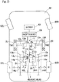
- Fig. 5 illustrates an electric vehicle to which the vehicle driving device is mounted.
- the left and right electric motors 2L, 2R are individually controlled by the drive source control device 67 ( Fig. 1 ), and thus can generate and output different torques.
- the torques of the electric motors 2L, 2R are respectively amplified in accordance with the gear ratios between the input gears 12a, 12a of the input gear shafts 12L, 12R and the large-diameter input-side external gears 13a, 13a of the intermediate gear shafts 13L, 13R in the power transmission device 3, and then transmitted to the ring gears R L , R R of the torque difference amplification device 30. Then, the torque difference between the left and the right is amplified by the torque difference amplification device 30, and the resultant torques are transmitted from the first and second connection members 31, 32 to the output-side small-diameter gears 13b, 13b.
- the torques are further amplified in accordance with the gear ratios between the output-side small-diameter gears 13b, 13b and the output gears 14a, 14a, respectively, and the resultant torques are outputted to the drive wheels 61L, 61R.
- the planetary gear mechanisms 30L, 30R of the torque difference amplification device 30 respectively include: the sun gears S L , S R and the ring gears R L , R R , which are provided coaxially; the planetary gears P L , P R located between the sun gears S L , S R and the ring gears R L , R R ; and the planetary carriers C L , C R which rotatably support the planetary gears P L , P R and are provided coaxially with the sun gears S L , S R and the ring gears R L , R R .
- the sun gears S L , S R and the planetary gears P L , P R are external-tooth gears having gear teeth on the outer circumferences
- the ring gears R L , R R are internal-tooth gears having gear teeth on the inner circumferences.
- the planetary gears P L , P R are engaged with the sun gears S L , S R and the ring gears R L , R R , respectively.
- the torque difference amplification device 30 is configured such that the left planetary gear mechanism 30L including the sun gear S L , the planetary carrier C L , the planetary gear P L , and the ring gear R L , and the right planetary gear mechanism 30R including the sun gear S R , the planetary carrier C R , the planetary gear P R , and the ring gear R R , are assembled together on a common axis, as described above.
- the first connection member 31 is formed to couple the planetary carrier C L which is a constituent member of the left planetary gear mechanism 30L, and the sun gear S R which is a constituent member of the right planetary gear mechanism 30R.
- the second connection member 32 is formed to couple the sun gear S L which is a constituent member of the left planetary gear mechanism 30L, and the planetary carrier C R which is a constituent member of the right planetary gear mechanism 30R.
- a torque TM1 generated by the left electric motor 2L is transmitted from the input gear shaft 12L to the intermediate gear shaft 13L. Then, while the torque difference between the left and the right is amplified by the torque difference amplification device 30, the torque transmitted to the intermediate gear shaft 13L is sequentially transmitted via the left planetary gear mechanism 30L to the output-side small-diameter gear 13b and the output gear 14a of the intermediate gear shaft 13L, and then the output gear shaft 14L. Then, a driving torque TL ( Fig. 6 ) is outputted from the output gear shaft 14L to the drive wheel 61L. A torque TM2 generated by the right electric motor 2R is transmitted from the input gear shaft 12R to the intermediate gear shaft 13R.
- the torque transmitted to the intermediate gear shaft 13R is sequentially transmitted via the right planetary gear mechanism 30R to the output-side small-diameter gear 13b and the output gear 14a of the intermediate gear shaft 13R, and then the output gear shaft 14R.
- a driving torque TR ( Fig. 6 ) is outputted from the output gear shaft 14R to the drive wheel 61R.
- the second connection member 32 is formed so as to include a hollow shaft extending along the axis of the torque difference amplification device 30, and the first connection member 31 is inserted to the inside of the hollow shaft.
- the first connection member 31 is formed so as to include a shaft extending along the axis of the torque difference amplification device 30.
- the first and second connection members 31, 32 are arranged coaxially with each other, and their shafts have an overlapping structure.
- the bearings 45, 46 are located between the outer circumferential surface of the first connection member 31 and the inner circumferential surface of the second connection member 32.
- the first and second connection members 31, 32 are supported with each other via the bearings 45, 46.
- the first and second connection members 31, 32 are rotatably supported by the thrust bearing 47 and the deep groove ball bearing 49. Besides the bearings 47, 49, there are the additional bearings 45, 46 and the thrust bearing 48 that are provided between the first and second connection members 31, 32.
- the torque difference amplification device 30 Since the torque difference amplification device 30 is formed from the assembly of the two identical single-pinion planetary gear mechanisms 30L, 30R, the torque difference amplification device 30 can be expressed by two velocity diagrams as shown in Fig. 6 .
- the two velocity diagrams are shifted upward and downward, so that the upper side in the drawing in Fig. 6 shows the velocity diagram of the left planetary gear mechanism 30L, and the lower side in the drawing in Fig. 6 shows the velocity diagram of the right planetary gear mechanism 30R.
- the torques TM1 and TM2 outputted from the respective electric motors 2L, 2R are respectively inputted to the ring gears R L , R R via the input-side external gears 13a, 13a engaged with the input gears 12a, 12a of the input gear shafts 12L, 12R, and thus the magnitudes of the torques TM1 and TM2 are changed in accordance with the reduction ratios.
- the driving torques TL, TR outputted from the torque difference amplification device 30 are respectively transmitted to the left and right drive wheels 61L, 61R via the output-side small-diameter gears 13b, 13b engaged with the output gears 14a, 14a, and thus the magnitudes of the driving torques TL, TR are changed in accordance with the reduction ratios.
- the distance between the ring gear R L and the planetary carrier C L is equal to the distance between the ring gear R and the planetary carrier C R .
- This distance is defined as "a”.
- the distance between the sun gear S L and the planetary carrier C L is equal to the distance between the sun gear S R and the planetary carrier C R . This distance is defined as "b”.
- the ratio between the length from the respective planetary carriers C L , C R to the ring gears R L , R R is equal to the ratio between a reciprocal (1/Zr) of a number Zr of teeth of the ring gear R L , R R .
- (2a + b) / b represents a torque difference amplification factor ⁇ .
- the torques from the electric motors 2L, 2R are inputted to the ring gears R L , R R , respectively, and the torques to the drive wheels 61L, 61R ( Fig. 5 ) are outputted from the sun gears and the planetary carriers, i.e., S R + C L and S L + C R , respectively.
- the rotation angular velocities of the left and right electric motors 2L, 2R also depend on the rotation angular velocities of the left and right drive wheels 61L, 61R and the numbers of teeth of the gears included in the power transmission device 3.
- the numbers of teeth of the gears included in the power transmission device 3 are the numbers of teeth of the gears of the input gear shafts 12L, 12R, the intermediate gear shafts 13L, 13R, the output gear shafts 14L, 14R, and the torque difference amplification device 30 in Fig. 2 .
- the "numbers of teeth of the gears included in the power transmission device 3" are simply referred to as "numbers of teeth of gears”.
- the torques of the left and right electric motors 2L, 2R are defined as TM1, TM2, the torques of the left and right drive wheels 61L, 61R are defined as TWL, TWR, and the angular accelerations of the left and right drive wheels 61L, 61R are defined as ⁇ WL', ⁇ WR'. Then, the following relational expressions are satisfied.
- TWL C 1 ⁇ TM 1 ⁇ C 2 ⁇ TM 2 ⁇ D 1 ⁇ ⁇ ⁇ WL ′ + D 2 ⁇ ⁇ ⁇ WR ′
- TWR ⁇ E 1 ⁇ TM 1 + E 2 ⁇ TM 2 + F 1 ⁇ ⁇ ⁇ WL ′ ⁇ F 2 ⁇ ⁇ ⁇ WR ′
- C1, C2, E1, and E2 are constants determined by the numbers of teeth of gears, and they are all positive values.
- D1, D2, F1, and F2 are constants determined by the numbers of teeth of gears and the moments of inertia of rotary portions such as the drive wheels, the gear shafts, and the electric motors 2L, 2R, and they are all positive values (the same applies to expression (8) and expression (9) described later). That is, the third term and the fourth term on the right-hand side of each of expression (6) and expression (7) represent an inertial force.
- Such torques on the left and right drive wheels 61L, 61R are exerted also by the angular acceleration of the right drive wheel 61R.
- the angular acceleration of the drive wheel 61L (61R) is used in expression (6) and expression (7)
- the angular velocities of the electric motors 2L, 2R may be used by using the relational expressions of expression (4) and expression (5).
- braking/driving torque command values for the left and right drive wheels 61L, 61R supplied from the high-order ECU 66 are defined as TL, TR.
- the drive source control device corrects the braking/driving torque command values TL, TR by an amount corresponding to the above torque caused by the angular acceleration of each drive wheel 61L, 61R in accordance with the following expressions (8), (9), and thereby can determine motor torque command values for the two electric motors 2L, 2R.
- Fig. 7 is a block diagram of a control system of the drive source control device 67.
- the drive source control device 67 includes a torque correction module (correction module) 68, a torque conversion module 69, an angular velocity conversion module 70, an angular acceleration calculation module 71, and an inertial force calculation module 72.
- the angular velocity conversion module 70 receives the angular velocities (motor angular velocities) of the two electric motors 2L, 2R ( Fig. 1 ) from the inverter device 64, and converts them to drive wheel angular velocities corresponding to the rotation speeds of the left and right drive wheels 61L, 61R ( Fig. 1 ), respectively.
- the angular acceleration calculation module 71 calculates the drive wheel angular accelerations of the left and right drive wheels 61L, 61R ( Fig. 1 ) from the respective drive wheel angular velocities supplied from the angular velocity conversion module 70. From the drive wheel angular accelerations of the left and right drive wheels 61L, 61R ( Fig. 1 ), the inertial force calculation module 72 calculates inertial forces to be used for correction for torques by the torque correction module 68.
- the inertial forces of the left and right drive wheels 61L, 61R ( Fig. 1 ) calculated by the inertial force calculation module 72 are calculated using the above expression (6) and expression (7). These inertial forces are calculated as values converted to torques occurring in the drive wheels. For the calculation of the inertial forces, constants calculated in advance on the basis of the numbers of teeth of gears and the moments of inertia of the rotary portions such as the drive wheels, the gear shafts, and the left and right electric motors 2L, 2R ( Fig. 1 ), are used, as described above.
- the torque correction module 68 calculates corrected braking/driving torque command values in accordance with the above expressions (8) and (9), so as to correct the braking/driving torque command values TL, TR for the left and right drive wheels 61L, 61R ( Fig. 1 ) supplied from a command module 66a of the high-order ECU 66, according to the inertial forces supplied from the inertial force calculation module 72.
- the corrected braking/driving torque command values are converted or transformed to motor torque command values by the torque conversion module 69, and then outputted to the inverter device 64.
- torque correction is performed with the inertial forces that have been converted to torques occurring in the drive wheels. However, correction may be performed after the inertial forces and the braking/driving torque command values are converted to values corresponding to the motor torques.
- the drive source control device 67 corrects the braking/driving torque command values for the left and right drive wheels 61L, 61R received from the high-order ECU 66, in consideration of the inertial forces.
- correction is performed by an amount corresponding to the inertial force so as to add a braking force for the second drive wheel 61R (61L)
- correction is performed by an amount corresponding to the inertial force so as to add a driving force for the drive wheel 61L (61R) in which change in angular velocity has occurred.
- correction is performed by an amount corresponding to the inertial force so as to add a driving force for the second drive wheel 61R (61L), and correction is performed by an amount corresponding to the inertial force so as to add a braking force for the drive wheel 61L (61R) in which change in angular velocity has occurred.
- the command values are corrected so as to eliminate the influence of the inertial force.
- inertial forces determined by their moments of inertia and angular accelerations are calculated, and the command values are corrected by amounts corresponding to these inertial forces.
- Fig. 8 shows a block diagram of a drive source control device 67 according to the second embodiment.
- a correction necessity determination module (determination module) 73 is additionally included as compared to the drive source control device 67 ( Fig. 7 ) according to the second embodiment.
- the correction necessity determination module 73 determines whether or not torque correction is needed, on the basis of the magnitudes of the left and right drive wheel angular accelerations, and outputs a result of the determination to the torque correction module 68. Specifically, if the angular acceleration of at least one of the drive wheels is greater than a predetermined threshold value, the correction necessity determination module 73 determines that torque correction is needed. In response to a result of the determination that torque correction is needed, the torque correction module 68 corrects the braking/driving torque command values on the basis of the inertial force.
- the correction necessity determination module 73 determines that torque correction is not needed, and correction for the braking/driving torque command values by the torque correction module 68 is not performed. As described above, when the angular accelerations of the drive wheels 61L, 61R are small, torque correction is not performed, whereby the calculation load on the drive source control device 67 can be suppressed and unnecessary torque variation due to torque correction being constantly performed can be suppressed.
- the first connection member 31 is formed to couple the planetary carrier C L of the left planetary gear mechanism 30L, and the sun gear S R of the right planetary gear mechanism 30R
- the second connection member 32 is formed to couple the sun gear S L of the left planetary gear mechanism 30L and the planetary carrier C R of the right planetary gear mechanism 30R.
- the configuration is not limited to this example.
- first connection member 31 may be formed to couple the sun gear S L of the left planetary gear mechanism 30L and the ring gear R R of the right planetary gear mechanism 30R
- second connection member 32 may be formed to couple the ring gear R L of the left planetary gear mechanism 30L and the sun gear S R of the right planetary gear mechanism 30R.
- connection member 32 may be formed to couple the planetary carrier C L of the left planetary gear mechanism 30L and the ring gear R R of the right planetary gear mechanism 30R.
- the drive sources of the vehicle driving device are not limited to electric motors, but may be an internal combustion engine such as a gasoline engine.
- the bearings 45, 46 between the first and second connection members 31, 32 may be bearings other than needle roller bearings.
- rolling bearings such as deep groove ball bearings or angular contact ball bearings may be used.
Landscapes
- Engineering & Computer Science (AREA)
- Mechanical Engineering (AREA)
- Transportation (AREA)
- General Engineering & Computer Science (AREA)
- Power Engineering (AREA)
- Chemical & Material Sciences (AREA)
- Combustion & Propulsion (AREA)
- Physics & Mathematics (AREA)
- General Physics & Mathematics (AREA)
- Automation & Control Theory (AREA)
- Life Sciences & Earth Sciences (AREA)
- Sustainable Development (AREA)
- Sustainable Energy (AREA)
- Retarders (AREA)
- Electric Propulsion And Braking For Vehicles (AREA)
Abstract
Description
- This application is based on and claims Convention priority to Japanese patent application No.
2016-195603, filed October 3, 2016 - The present invention relates to a drive source control device, and for example, relates to a drive source control device for a vehicle driving device which transmits driving torques generated from two independent drive sources, to left and right drive wheels, with a torque difference therebetween amplified.
- In order to achieve smooth turning traveling of a vehicle or suppress change in the behavior of a vehicle such as extreme understeer or extreme oversteer, it may be effective to generate a great driving torque difference between left and right drive wheels. A vehicle driving device is thus disclosed in which a gear device having two planetary gear mechanisms combined is provided between two drive sources and left and right drive wheels so as to amplify the torque difference (
Patent Documents 1 and 2). - For a device that generates a torque difference between left and right wheels of a vehicle, a control device is disclosed which performs correction by an inertial force of a motor in the generation of the torque difference (Patent Document 3).
-
- [Patent Document 1]
JP Laid-open Patent Publication No. 2015-21594 - [Patent Document 2]
JP Patent No. 4907390 - [Patent Document 3]
JP Laid-open Patent Publication No. 2011-130628 - In the vehicle driving device shown in
Patent Documents 1 and 2, in the case where angular velocity changes in one of the left and right drive wheels, an inertial force depending on a moment of inertia and angular accelerations of a wheel, a gear shaft, a motor, and the like to which the angular velocity change transfers, is transferred as a torque to the other drive wheel via the planetary gear mechanism in the gear device. For example, if the drive wheel on the turning inner wheel side lifts and spins while the vehicle is turning and accelerating, the inertial force is applied as a driving torque to the drive wheel on the turning outer wheel side, so that a torque different from a command torque issued from a high-order ECU is outputted. As a result, the behavior of the vehicle might become unstable. - In
Patent Document 3, the inertial force is calculated from a rotation speed difference between the left and right wheels and the moment of inertia of the motor, to correct the torque. However, in the vehicle driving device having the configuration shown inPatent Documents 1 and 2, since a rotation speed difference between the left and right wheels is caused by a rotation speed difference between two motors, it is difficult to appropriately correct the torque by only the inertial force of one motor. - An object of the present invention is to provide a drive source control device that, even in the case where angular velocity changes in one or both of the left and right drive wheels, can output a torque in accordance with a supplied command value and stabilize the behavior of the vehicle.
- In the following description, the reference characters in the embodiments are used for convenience sake in order to facilitate the understanding.
- A drive
source control device 67 according to the present invention is a drivesource control device 67 for controlling twodrive sources drive sources right drive wheels power transmission device 3 disposed among the twodrive sources right drive wheels power transmission device 3 being configured to distribute powers from the twodrive sources right drive wheels right drive wheels source control device 67 includes: an angularacceleration calculation module 71 configured to calculate either (a) angular accelerations of the respective left andright drive wheels respective drive sources correction module 68 configured to, using the angular accelerations calculated by the angularacceleration calculation module 71 and in accordance with a predetermined condition, correct command values for respective outputs of the twodrive sources command module 66a. - The predetermined condition is any condition that is determined depending on designing or the like, and is, for example, determined by figuring out an appropriate condition through examination and/or simulation.
- In the above configuration, the angular
acceleration calculation module 71 calculates the angular accelerations of therespective drive wheels respective drive sources correction module 68 corrects the command values for respective outputs of the tworespective drive sources command module 66a, in accordance with a predetermined condition. For example, when an angular acceleration occurs in onedrive wheel 61L (61R) of the left andright drive wheels respective drive sources other drive wheel 61R (61L) of the left andright drive wheels right drive wheels command module 66a. Thus, the vehicle behavior can be stabilized. - The
correction module 68 may be configured to correct the command values for the respective outputs of the tworespective drive sources acceleration calculation module 71, and in accordance with a moment of inertia of a predetermined rotary portion and a number of teeth of a gear of thepower transmission device 3. The predetermined rotary portion is any rotary portion (rotary component or rotary part) determined depending on designing or the like, and is, for example, determined by figuring out an appropriate rotary portion through examination and/or simulation. The above configuration enables thecorrection module 68 to correct the command values for respective outputs of the twodrive sources - The
power transmission device 3 may include a torquedifference amplification device 30. The torquedifference amplification device 30 has twoplanetary gear mechanisms drive sources difference amplification device 30 amplifying the difference between torques generated by the twodrive sources difference amplification device 30 as described above, it is possible to output torques in accordance with the command values supplied from thecommand module 66a. - The
correction module 68 may be configured to correct the command values for the respective outputs of the tworespective drive sources right drive wheels correction module 68 may be configured to correct the command values for the respective outputs of the tworespective drive sources respective drive sources - The
correction module 68 may be configured to correct the command values for the respective outputs of the twodrive sources drive wheel 61L (61R) of the left andright drive wheels other drive wheel 61R (61L) of the left and right drive wheels. Thus, for theother drive wheel 61R (61L), it is possible to perform correction based on the inertial force so as to apply a torque in a direction opposite to the direction of the angular acceleration of the onedrive wheel 61L (61R). - The
correction module 68 may be configured to correct the command values for the respective outputs of the tworespective drive sources drive wheel 61L (61R) of the left andright drive wheels drive wheel 61L (61R). Thus, for thedrive wheel 61L (61R) in which the angular acceleration occurs, it is possible to perform correction based on the inertial force so as to apply a torque in the same direction as the direction of the angular acceleration. - A
determination module 73 may be provided which is configured to determine whether or not the angular acceleration calculated by the angularacceleration calculation module 71 is greater than a threshold value, and only when thedetermination module 73 determines that the angular acceleration is greater than the threshold value, thecorrection module 68 may correct the command values for the respective outputs of the tworespective drive sources drive wheels source control device 67 can be suppressed and unnecessary torque variation due to torque correction being constantly performed can be suppressed. - A vehicle according to the present invention is the vehicle including the drive
source control device 67. In this case, even if undesired change in angular velocity occurs in one or both of the left andright drive wheels command module 66a. Thus, the vehicle behavior can be stabilized. - Any combination of at least two constructions, disclosed in the appended claims and/or the specification and/or the accompanying drawings should be construed as included within the scope of the present invention. In particular, any combination of two or more of the appended claims should be equally construed as included within the scope of the present invention.
- In any event, the present invention will become more clearly understood from the following description of preferred embodiments thereof, when taken in conjunction with the accompanying drawings. However, the embodiments and the drawings are given only for the purpose of illustration and explanation, and are not to be taken as limiting the scope of the present invention in any way whatsoever, which scope is to be determined by the appended claims. In the accompanying drawings, like reference numerals are used to denote like parts throughout the several views, and:
-
Fig. 1 is a block diagram showing the conceptual configuration of a vehicle provided with a drive source control device according to the first embodiment of the present invention, and a vehicle driving device; -
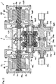
Fig. 2 is a sectional view of the vehicle driving device shown inFig. 1 ; -
Fig. 3 is an enlarged sectional view showing a torque difference amplification device part of the vehicle driving device shown inFig. 1 ; -
Fig. 4 is a skeleton diagram showing the vehicle driving device shown inFig. 1 ; -
Fig. 5 illustrates an electric vehicle to which the vehicle driving device shown inFig. 1 is mounted; -
Fig. 6 shows velocity diagrams for illustrating a torque difference amplification factor of the vehicle driving device shown inFig. 1 ; -
Fig. 7 is a block diagram of a control system of the drive source control device shown inFig. 1 ; and -
Fig. 8 is a block diagram of a control system of a drive source control device according to the second embodiment of the present invention. - A drive source control device according to the first embodiment of the present invention and a vehicle provided with the drive source control device will be described with reference to
Fig. 1 to Fig. 7 .Fig. 1 is a block diagram showing the conceptual configuration of a vehicle (electric vehicle) provided with the drive source control device and a vehicle driving device. This vehicle is a rear wheel drive type, and includes achassis 60,drive wheels front wheels vehicle driving device 1, a high-order ECU 66, a drivesource control device 67, abattery 63, aninverter device 64, and the like. - The
vehicle driving device 1 includes first and secondelectric motors power transmission device 3. The first and secondelectric motors electric motors drive wheels - The high-
order ECU 66 is a high-order control means for the drivesource control device 67, and for example, has a function of performing integrated control and cooperative control for the entire vehicle, and a function of generating braking/driving torque command values for the left andright drive wheels order ECU 66 generates braking/driving torque command values (command values for outputs) for left and right, on the basis of an acceleration command outputted from an acceleration manipulation unit (not shown), a deceleration command outputted from a brake manipulation unit (not shown), and a turning command outputted from a steering angle sensor or the like (not shown). - The drive
source control device 67 supplies motor torque command values to theinverter device 64 on the basis of the braking/driving torque command values for left and right supplied from the high-order ECU 66. Thus, the first and secondelectric motors inverter device 64 converts DC power of thebattery 63 to AC power for driving the first and secondelectric motors inverter device 64 controls a current supplied from thebattery 63 and drives the first and secondelectric motors electric motors vehicle driving device 1 are transmitted to the left andright drive wheels - In the present embodiment, the first and second
electric motors vehicle driving device 1 are electric motors having the same maximum output and based on the same standard. As shown inFig. 2 , the first and secondelectric motors motor housings stators rotors electric motors stators motor housings rotor 5 is provided on the inner circumference of eachstator 6 with a gap therebetween. - The
motor housings power transmission device 3. The inner side walls 4cL, 4cR have openings through whichmotor shafts 5a are led out to the inboard side. As used herein, in a state where thevehicle driving device 1 is mounted to the vehicle, a side outward in the vehicle width direction of the vehicle is referred to as outboard side, and a side toward the center in the vehicle width direction of the vehicle is referred to as inboard side. - The
stators rotor 5 has themotor shaft 5a at the center part. The inner side walls 4cL, 4cR are each provided with a rollingbearing 8a, and the outer side walls 4bL, 4bR are also each provided with a rollingbearing 8b. Themotor shafts motor housings bearings right motor shafts - The
power transmission device 3 has a powertransmission device housing 9. Further, thepower transmission device 3 has two left and rightinput gear shafts intermediate gear shafts output gear shafts difference amplification device 30. Thepower transmission device 3 amplifies a difference between torques (driving torques) inputted from themotor shafts 5a of the first and secondelectric motors difference amplification device 30, and transmits the resultant torques to thedrive wheels Fig. 1 ). - The power
transmission device housing 9 houses the above gear shafts and the torquedifference amplification device 30. The powertransmission device housing 9 has such a three-piece structure as to be divided into three pieces in a direction perpendicular to the axial direction of the gear shafts. Specifically, the powertransmission device housing 9 has acenter housing 9a and left and right lateral housings 9bL, 9bR fixed to respective side surfaces of thecenter housing 9a. - The side surfaces on the outboard side of the lateral housings 9bL, 9bR, and the inner side walls 4cL, 4cR, are fixed to each other by a plurality of bolts. Thus, the two
electric motors transmission device housing 9. Thecenter housing 9a is provided with a partition wall 11 at the center. The powertransmission device housing 9 is divided into two chambers at the left and the right by the partition wall 11, and these parts house a body portion of thepower transmission device 3. The body portion of thepower transmission device 3 is symmetric between the left and the right, and includes theinput gear shafts intermediate gear shafts output gear shafts difference amplification device 30. - Each of the
input gear shafts input gear 12a to which a power is transmitted from thecorresponding motor shaft 5a.Rolling bearings 17a are provided in bearing fitting holes formed in the partition wall 11, and rollingbearings 17b are provided in bearing fitting holes formed in the left and right lateral housings 9bL, 9bR. Both ends of eachinput gear shaft transmission device housing 9 via the rollingbearings input gear shafts motor shafts 5a are inserted into the hollow inner parts of theinput gear shafts input gear shafts motor shafts 5a are spline-coupled with each other ("serration" coupling is also included; also for spline coupling below, "serration" coupling is included). - As shown in
Fig. 3 , the left and rightintermediate gear shafts intermediate gear shafts external gears output gears Rolling bearings 20a are provided in bearingfitting holes 19a formed in the partition wall 11, and rollingbearings 20b are provided in bearingfitting holes 19b formed in the left and right lateral housings 9bL, 9bR. Both ends of eachintermediate gear shaft transmission device housing 9 via the rollingbearings fitting holes bearings second connection members - To the
intermediate gear shafts difference amplification device 30 is assembled coaxially with theintermediate gear shafts difference amplification device 30 amplifies a difference between torques (driving torques) supplied from the twoelectric motors Fig. 2 ). The torquedifference amplification device 30 has twoplanetary gear mechanisms planetary gear mechanisms planetary gear mechanisms - The
planetary gear mechanisms planetary gear mechanisms second connection members external gears intermediate gear shafts intermediate gear shafts - The
first connection member 31 couples the left planetary carrier CL which is a constituent member of theplanetary gear mechanism 30L at the left in the drawing inFig. 3 , and the right sun gear SR which is a constituent member of theplanetary gear mechanism 30R at the right in the drawing inFig. 3 . Thesecond connection member 32 couples the left sun gear SL which is a constituent member of theplanetary gear mechanism 30L at the left in the drawing inFig. 3 , and the right planetary carrier CR which is a constituent member of theplanetary gear mechanism 30R at the right in the drawing inFig. 3 . - The planetary carriers CL, CR have carrier pins 33, 33 supporting the planetary gears PL, PR,
carrier flanges carrier flanges needle roller bearings carrier flanges carrier flanges - The
carrier flanges hollow shaft portions hollow shaft portions bearings fitting holes carrier flanges hollow shaft portions hollow shaft portions bearings fitting holes bearings carrier flanges planetary gear mechanism 30L at the left in the drawing, and between the ring gear RR and the outer circumferential surfaces of thecarrier flanges planetary gear mechanism 30R at the right in the drawing. - The first and
second connection members planetary gear mechanisms center housing 9a (Fig. 2 ) into the left and right chambers. The first andsecond connection members thrust bearing 47 and rotatably supported in the radial direction by a deepgroove ball bearing 49. Further, besides thebearings additional bearings thrust bearing 48 are provided between the first andsecond connection members additional bearings second connection member 32 has a hollow shaft, and thefirst connection member 31 has a shaft to be inserted into the hollow shaft. - The outer circumferential surface on the outboard side at the right in the drawing in
Fig. 3 , of thesecond connection member 32, and thehollow shaft portion 36 of thecarrier flange 34b on the inboard side, of the planetary carrier CR, have splines to be engaged with each other. Thus, thesecond connection member 32 is connected to the planetary carrier CR by spline fitting. Accordingly, the planetary carrier CR which is a second rotary member rotates integrally with thesecond connection member 32. - The outer circumferential surface on the outboard side at the left in the drawing in
Fig. 3 , of thefirst connection member 31, and thehollow shaft portion 35 of thecarrier flange 34a on the outboard side, of the planetary carrier CL, have splines to be engaged with each other. Thus, thefirst connection member 31 is connected to the planetary carrier CL by spline fitting. Accordingly, the planetary carrier CL which is a first rotary member rotates integrally with thefirst connection member 31. - As described above, the first and
second connection members planetary gear mechanisms transmission device housing 9 from the left and the right, together with another speed reducing gear shaft. The end portion on the planetary carrier CL side of thesecond connection member 32 has, on the outer circumferential surface thereof, an external gear forming the sun gear SL of theplanetary gear mechanism 30L at the left in the drawing inFig. 3 . The external gear forming the sun gear SL is engaged with the planetary gear PL. - The
first connection member 31 has a large-diameter portion 43 at an end on theplanetary gear mechanism 30R side at the right in the drawing inFig. 3 . The outer circumferential surface of the large-diameter portion 43 has an external gear forming the sun gear SR of theplanetary gear mechanism 30R at the right in the drawing inFig. 3 . The external gear forming the sun gear SR is engaged with the planetary gear PR. Thethrust bearings second connection member 32. By thesethrust bearings second connection members Fig. 3 , of thefirst connection member 31, is supported by the deepgroove ball bearing 49 with respect to the planetary carrier CR. Thefirst connection member 31 has an oil hole at the axis thereof. - As shown in
Fig. 2 , theoutput gear shafts Rolling bearings bearings output gear shafts transmission device housing 9 via the rollingbearings - The outboard-side ends of the
output gear shafts transmission device housing 9 through openings formed in the lateral housings 9bL, 9bR, respectively. Outer joint portions of constant-velocity joints 65a are spline-coupled with the outer circumferential surfaces at the outboard-side ends of theoutput gear shafts velocity joints 65a are connected to therespective drive wheels Fig. 1 ) via intermediate shafts and the like (not shown). -
Fig. 4 is a skeleton diagram showing the vehicle driving device.Fig. 5 illustrates an electric vehicle to which the vehicle driving device is mounted. As shown inFig. 4 andFig. 5 , the left and rightelectric motors Fig. 1 ), and thus can generate and output different torques. - The torques of the
electric motors input gear shafts external gears intermediate gear shafts power transmission device 3, and then transmitted to the ring gears RL, RR of the torquedifference amplification device 30. Then, the torque difference between the left and the right is amplified by the torquedifference amplification device 30, and the resultant torques are transmitted from the first andsecond connection members drive wheels - The
planetary gear mechanisms difference amplification device 30 respectively include: the sun gears SL, SR and the ring gears RL, RR, which are provided coaxially; the planetary gears PL, PR located between the sun gears SL, SR and the ring gears RL, RR; and the planetary carriers CL, CR which rotatably support the planetary gears PL, PR and are provided coaxially with the sun gears SL, SR and the ring gears RL, RR. Here, the sun gears SL, SR and the planetary gears PL, PR are external-tooth gears having gear teeth on the outer circumferences, and the ring gears RL, RR are internal-tooth gears having gear teeth on the inner circumferences. The planetary gears PL, PR are engaged with the sun gears SL, SR and the ring gears RL, RR, respectively. - In the
planetary gear mechanisms Fig. 6 , the ring gears RL, RR and the sun gears SL, SR are depicted on opposite sides with respect to the planetary carriers CL, CR. - As shown in
Fig. 4 andFig. 5 , the torquedifference amplification device 30 is configured such that the leftplanetary gear mechanism 30L including the sun gear SL, the planetary carrier CL, the planetary gear PL, and the ring gear RL, and the rightplanetary gear mechanism 30R including the sun gear SR, the planetary carrier CR, the planetary gear PR, and the ring gear RR, are assembled together on a common axis, as described above. - The
first connection member 31 is formed to couple the planetary carrier CL which is a constituent member of the leftplanetary gear mechanism 30L, and the sun gear SR which is a constituent member of the rightplanetary gear mechanism 30R. Thesecond connection member 32 is formed to couple the sun gear SL which is a constituent member of the leftplanetary gear mechanism 30L, and the planetary carrier CR which is a constituent member of the rightplanetary gear mechanism 30R. - A torque TM1 generated by the left
electric motor 2L is transmitted from theinput gear shaft 12L to theintermediate gear shaft 13L. Then, while the torque difference between the left and the right is amplified by the torquedifference amplification device 30, the torque transmitted to theintermediate gear shaft 13L is sequentially transmitted via the leftplanetary gear mechanism 30L to the output-side small-diameter gear 13b and theoutput gear 14a of theintermediate gear shaft 13L, and then theoutput gear shaft 14L. Then, a driving torque TL (Fig. 6 ) is outputted from theoutput gear shaft 14L to thedrive wheel 61L. A torque TM2 generated by the rightelectric motor 2R is transmitted from theinput gear shaft 12R to theintermediate gear shaft 13R. Then, while the torque difference between the left and the right is amplified by the torquedifference amplification device 30, the torque transmitted to theintermediate gear shaft 13R is sequentially transmitted via the rightplanetary gear mechanism 30R to the output-side small-diameter gear 13b and theoutput gear 14a of theintermediate gear shaft 13R, and then theoutput gear shaft 14R. Then, a driving torque TR (Fig. 6 ) is outputted from theoutput gear shaft 14R to thedrive wheel 61R. - The
second connection member 32 is formed so as to include a hollow shaft extending along the axis of the torquedifference amplification device 30, and thefirst connection member 31 is inserted to the inside of the hollow shaft. Thefirst connection member 31 is formed so as to include a shaft extending along the axis of the torquedifference amplification device 30. The first andsecond connection members bearings first connection member 31 and the inner circumferential surface of thesecond connection member 32. The first andsecond connection members bearings second connection members thrust bearing 47 and the deepgroove ball bearing 49. Besides thebearings additional bearings second connection members - Here, driving torques transmitted by the torque
difference amplification device 30 will be described with reference to the velocity diagrams shown inFig. 6 . Since the torquedifference amplification device 30 is formed from the assembly of the two identical single-pinionplanetary gear mechanisms difference amplification device 30 can be expressed by two velocity diagrams as shown inFig. 6 . Here, for facilitating the understanding, the two velocity diagrams are shifted upward and downward, so that the upper side in the drawing inFig. 6 shows the velocity diagram of the leftplanetary gear mechanism 30L, and the lower side in the drawing inFig. 6 shows the velocity diagram of the rightplanetary gear mechanism 30R. - In practice, as shown in
Fig. 5 , the torques TM1 and TM2 outputted from the respectiveelectric motors external gears input gear shafts difference amplification device 30 are respectively transmitted to the left andright drive wheels - Although the torques are changed in accordance with the above reduction ratios in this vehicle driving device, hereinafter, for facilitating the understanding, as shown in
Fig. 6 , it is assumed that the reduction ratios are 1, and thus the torques inputted to the ring gears RL, RR remain TM1, TM2 and the driving torques remain TL, TR, in the description of the velocity diagrams and calculation expressions. - In the two single-pinion
planetary gear mechanisms - The ratio between the length from the respective planetary carriers CL, CR to the ring gears RL, RR is equal to the ratio between a reciprocal (1/Zr) of a number Zr of teeth of the ring gear RL, RR. The ratio between the length from the respective planetary carriers CL, CR to the sun gears SL, SR is equal to the ratio between a reciprocal (1/Zs) of a number Zs of teeth of the sun gear SL, SR. Therefore, a = (1/Zr) and b = (1/Zs) are satisfied.
- From balance of a moment M with a point of RR as a reference, the following expression (1) is satisfied. In
Fig. 6 , an arrow direction M in the drawing is the positive direction of the moment.
- From balance of a moment M with a point of RL as a reference, the following expression (2) is satisfied.

- From expression (1) + expression (2), the following expression (3) is obtained.

- In expression (3), (2a + b) / b represents a torque difference amplification factor α. By substituting a = 1/Zr and b = 1/Zs, α = (Zr + 2Zs) / Zr is obtained. That is, the following torque difference amplification factor α is obtained.

- In this example, the torques from the
electric motors Fig. 5 ) are inputted to the ring gears RL, RR, respectively, and the torques to thedrive wheels Fig. 5 ) are outputted from the sun gears and the planetary carriers, i.e., SR + CL and SL + CR, respectively. - As shown in
Fig. 5 andFig. 6 , in the case where a difference between the rotation speeds of thefirst connection member 31 and thesecond connection member 32 is small, if different torques TM1, TM2 are generated from the twoelectric motors difference amplification device 30, whereby a driving torque difference α ∗ ΔTIN greater than the input torque difference ΔTIN can be obtained. - That is, even if the input torque difference ΔTIN is small, the input torque difference ΔTIN can be amplified with the torque difference amplification factor α (= (Zr + 2Zs) / Zr) by the torque
difference amplification device 30. Thus, a driving torque difference ΔTOUT (= α ∗ (TM2 - TM1)) greater than the input torque difference ΔTIN can be supplied between the driving torques TL, TR transmitted to theleft drive wheel 61L and theright drive wheel 61R. - As shown in
Fig. 1 , the rotation angular velocities of the left and rightelectric motors right drive wheels power transmission device 3. It is noted that the numbers of teeth of the gears included in thepower transmission device 3 are the numbers of teeth of the gears of theinput gear shafts intermediate gear shafts output gear shafts difference amplification device 30 inFig. 2 . Hereinafter, the "numbers of teeth of the gears included in thepower transmission device 3" are simply referred to as "numbers of teeth of gears". - If the rotation speeds of the left and right
electric motors right drive wheels 

right drive wheels electric motors electric motors drive wheel 61L (61R). - The torques of the left and right
electric motors right drive wheels right drive wheels 

electric motors - It is assumed that an angular acceleration in the accelerating direction with respect to the traveling direction occurs in the
left drive wheel 61L of the vehicle (ωWL' > 0). As shown in expression (6), by the angular acceleration in the accelerating direction of theleft drive wheel 61L, a torque in the decelerating direction acts on theleft drive wheel 61L. As shown in expression (7), by the angular acceleration in the accelerating direction of theleft drive wheel 61L, a torque in the accelerating direction acts on theright drive wheel 61R. - In the case where an angular acceleration in the decelerating direction occurs in the
left drive wheel 61L, torques in directions opposite to the above ones are exerted. That is, by the angular acceleration in the decelerating direction of theleft drive wheel 61L, a torque in the accelerating direction acts on theleft drive wheel 61L. By the angular acceleration in the decelerating direction of theleft drive wheel 61L, a torque in the decelerating direction acts on theright drive wheel 61R. - Such torques on the left and
right drive wheels right drive wheel 61R. Although the angular acceleration of thedrive wheel 61L (61R) is used in expression (6) and expression (7), the angular velocities of theelectric motors - Here, braking/driving torque command values for the left and
right drive wheels order ECU 66 are defined as TL, TR. The drive source control device corrects the braking/driving torque command values TL, TR by an amount corresponding to the above torque caused by the angular acceleration of eachdrive wheel electric motors 

-
Fig. 7 is a block diagram of a control system of the drivesource control device 67. - The drive
source control device 67 includes a torque correction module (correction module) 68, atorque conversion module 69, an angularvelocity conversion module 70, an angularacceleration calculation module 71, and an inertialforce calculation module 72. The angularvelocity conversion module 70 receives the angular velocities (motor angular velocities) of the twoelectric motors Fig. 1 ) from theinverter device 64, and converts them to drive wheel angular velocities corresponding to the rotation speeds of the left andright drive wheels Fig. 1 ), respectively. The angularacceleration calculation module 71 calculates the drive wheel angular accelerations of the left andright drive wheels Fig. 1 ) from the respective drive wheel angular velocities supplied from the angularvelocity conversion module 70. From the drive wheel angular accelerations of the left andright drive wheels Fig. 1 ), the inertialforce calculation module 72 calculates inertial forces to be used for correction for torques by thetorque correction module 68. - The inertial forces of the left and
right drive wheels Fig. 1 ) calculated by the inertialforce calculation module 72 are calculated using the above expression (6) and expression (7). These inertial forces are calculated as values converted to torques occurring in the drive wheels. For the calculation of the inertial forces, constants calculated in advance on the basis of the numbers of teeth of gears and the moments of inertia of the rotary portions such as the drive wheels, the gear shafts, and the left and rightelectric motors Fig. 1 ), are used, as described above. - The
torque correction module 68 calculates corrected braking/driving torque command values in accordance with the above expressions (8) and (9), so as to correct the braking/driving torque command values TL, TR for the left andright drive wheels Fig. 1 ) supplied from acommand module 66a of the high-order ECU 66, according to the inertial forces supplied from the inertialforce calculation module 72. The corrected braking/driving torque command values are converted or transformed to motor torque command values by thetorque conversion module 69, and then outputted to theinverter device 64. In the example shown inFig. 7 , torque correction is performed with the inertial forces that have been converted to torques occurring in the drive wheels. However, correction may be performed after the inertial forces and the braking/driving torque command values are converted to values corresponding to the motor torques. - As described above, the drive
source control device 67 according to the present embodiment corrects the braking/driving torque command values for the left andright drive wheels order ECU 66, in consideration of the inertial forces. In the case where change in angular velocity in the vehicle accelerating direction occurs in thefirst drive wheel 61L (61R), correction is performed by an amount corresponding to the inertial force so as to add a braking force for thesecond drive wheel 61R (61L), and correction is performed by an amount corresponding to the inertial force so as to add a driving force for thedrive wheel 61L (61R) in which change in angular velocity has occurred. - On the other hand, in the case where change in angular velocity in the vehicle decelerating direction occurs in the
first drive wheel 61L (61R), correction is performed by an amount corresponding to the inertial force so as to add a driving force for thesecond drive wheel 61R (61L), and correction is performed by an amount corresponding to the inertial force so as to add a braking force for thedrive wheel 61L (61R) in which change in angular velocity has occurred. In other words, the command values are corrected so as to eliminate the influence of the inertial force. In the case where change in angular velocity occurs in both of the left andright drive wheels - Therefore, even if undesired change in angular velocity occurs in one or both of the left and
right drive wheels command module 66a of the high-order ECU 66, which stabilizes the vehicle behavior. - The second embodiment will be described.
- In the following description, parts corresponding to the matters previously described in the preceding embodiments are denoted by the same reference characters and the same descriptions are omitted. When only part of the configuration is described, the other part of the configuration is the same as that previously described, unless otherwise specified. The same operations and effects are obtained from the same configuration. Not only parts specifically described in each embodiment can be combined, but also the embodiments can be partially combined with each other unless such a combination particularly causes a problem.
-
Fig. 8 shows a block diagram of a drivesource control device 67 according to the second embodiment. In the drivesource control device 67 according to the second embodiment, a correction necessity determination module (determination module) 73 is additionally included as compared to the drive source control device 67 (Fig. 7 ) according to the second embodiment. The correctionnecessity determination module 73 determines whether or not torque correction is needed, on the basis of the magnitudes of the left and right drive wheel angular accelerations, and outputs a result of the determination to thetorque correction module 68. Specifically, if the angular acceleration of at least one of the drive wheels is greater than a predetermined threshold value, the correctionnecessity determination module 73 determines that torque correction is needed. In response to a result of the determination that torque correction is needed, thetorque correction module 68 corrects the braking/driving torque command values on the basis of the inertial force. - If both of the accelerations of the left and right drive wheels are equal to or smaller than the threshold value, the correction
necessity determination module 73 determines that torque correction is not needed, and correction for the braking/driving torque command values by thetorque correction module 68 is not performed. As described above, when the angular accelerations of thedrive wheels source control device 67 can be suppressed and unnecessary torque variation due to torque correction being constantly performed can be suppressed. - In the embodiment shown in
Fig. 2 andFig. 3 , thefirst connection member 31 is formed to couple the planetary carrier CL of the leftplanetary gear mechanism 30L, and the sun gear SR of the rightplanetary gear mechanism 30R, and thesecond connection member 32 is formed to couple the sun gear SL of the leftplanetary gear mechanism 30L and the planetary carrier CR of the rightplanetary gear mechanism 30R. However, the configuration is not limited to this example. - For example, the
first connection member 31 may be formed to couple the sun gear SL of the leftplanetary gear mechanism 30L and the ring gear RR of the rightplanetary gear mechanism 30R, and thesecond connection member 32 may be formed to couple the ring gear RL of the leftplanetary gear mechanism 30L and the sun gear SR of the rightplanetary gear mechanism 30R. - Furthermore, the
second connection member 32 may be formed to couple the planetary carrier CL of the leftplanetary gear mechanism 30L and the ring gear RR of the rightplanetary gear mechanism 30R. - The drive sources of the vehicle driving device are not limited to electric motors, but may be an internal combustion engine such as a gasoline engine.
- The
bearings second connection members - Although the present invention has been described above in connection with the preferred embodiments with reference to the accompanying drawings, numerous additions, modifications, or deletions can be made without departing from the gist of the present invention. Accordingly, such additions, modifications, or deletions are to be construed as included in the scope of the present invention.
-
- 2L, 2R
- electric motor (drive source)
- 3
- power transmission device
- 61L, 61R
- drive wheel
- 66a
- command module
- 67
- drive source control device
- 68
- torque correction module (correction module)
- 71
- angular acceleration calculation module
Claims (9)
- A drive source control device for controlling two drive sources of a vehicle, the vehicle including
the two drive sources,
left and right drive wheels, and
a power transmission device disposed among the two drive sources and the left and right drive wheels, the power transmission device being configured to distribute powers from the two drive sources to the left and right drive wheels to drive the left and right drive wheels,
the drive source control device comprising:an angular acceleration calculation module configured to calculate either (a) angular accelerations of the respective left and right drive wheels or (b) angular accelerations of the two respective drive sources, or both (a) and (b); anda correction module configured to, using the angular accelerations calculated by the angular acceleration calculation module, correct command values for respective outputs of the two respective drive sources, the command values being supplied from a command module. - The drive source control device as claimed in claim 1, wherein
the correction module is configured to correct the command values for the respective outputs of the two respective drive sources, using the angular accelerations calculated by the angular acceleration calculation module, and in accordance with a moment of inertia of a predetermined rotary portion and a number of teeth of a gear of the power transmission device. - The drive source control device as claimed in claim 1 or 2, wherein
the power transmission device includes a torque difference amplification device, the torque difference amplification device having two planetary gear mechanisms, the torque difference amplification device amplifying a difference between torques generated by the two drive sources. - The drive source control device as claimed in any one of claims 1 to 3, wherein
the correction module is configured to correct the command values for the respective outputs of the two respective drive sources, using the angular acceleration of at least one of the left and right drive wheels. - The drive source control device as claimed in any one of claims 1 to 4, wherein
the correction module is configured to correct the command values for the respective outputs of the two respective drive sources, using the angular accelerations of the two respective drive sources. - The drive source control device as claimed in any one of claims 1 to 5, wherein
the correction module is configured to correct the command values for the respective outputs of the two respective drive sources, when an angular acceleration occurs in one drive wheel of the left and right drive wheels, so as to apply a torque in a direction opposite to a direction of the angular acceleration, to the other drive wheel of the left and right drive wheels. - The drive source control device as claimed in any one of claims 1 to 6, wherein
the correction module is configured to correct the command values for the respective outputs of the two respective drive sources, when an angular acceleration occurs in one drive wheel of the left and right drive wheels, so as to apply a torque in the same direction as a direction of the angular acceleration, to the one drive wheel. - The drive source control device as claimed in any one of claims 1 to 7, further comprising
a determination module configured to determine whether or not the angular acceleration calculated by the angular acceleration calculation module is greater than a threshold value, wherein
only when the determination module determines that the angular acceleration is greater than the threshold value, the correction module corrects the command values for the respective outputs of the two respective drive sources. - The vehicle comprising the drive source control device as claimed in any one of claims 1 to 8.
Applications Claiming Priority (2)
| Application Number | Priority Date | Filing Date | Title |
|---|---|---|---|
| JP2016195603A JP2018061306A (en) | 2016-10-03 | 2016-10-03 | Drive source control device |
| PCT/JP2017/035440 WO2018066464A1 (en) | 2016-10-03 | 2017-09-29 | Drive source control device |
Publications (2)
| Publication Number | Publication Date |
|---|---|
| EP3521097A1 true EP3521097A1 (en) | 2019-08-07 |
| EP3521097A4 EP3521097A4 (en) | 2020-05-27 |
Family
ID=61831668
Family Applications (1)
| Application Number | Title | Priority Date | Filing Date |
|---|---|---|---|
| EP17858302.7A Withdrawn EP3521097A4 (en) | 2016-10-03 | 2017-09-29 | Drive source control device |
Country Status (5)
| Country | Link |
|---|---|
| US (1) | US11207984B2 (en) |
| EP (1) | EP3521097A4 (en) |
| JP (1) | JP2018061306A (en) |
| CN (1) | CN109789800B (en) |
| WO (1) | WO2018066464A1 (en) |
Families Citing this family (11)
| Publication number | Priority date | Publication date | Assignee | Title |
|---|---|---|---|---|
| KR102478125B1 (en) * | 2017-11-24 | 2022-12-16 | 현대자동차주식회사 | Control method and system for motor drive vehicle |
| JP6521491B1 (en) * | 2017-12-01 | 2019-05-29 | マツダ株式会社 | Vehicle control device |
| DE102019100324A1 (en) * | 2019-01-08 | 2020-07-09 | Bayerische Motoren Werke Aktiengesellschaft | Device for calibrating two electric motors arranged on one axis in two-axis motor vehicles |
| US12240305B2 (en) * | 2019-03-06 | 2025-03-04 | Mitsubishi Jidosha Kogyo Kabushiki Kaisha | Left-right wheel driving device |
| JP7417185B2 (en) * | 2019-11-01 | 2024-01-18 | 三菱自動車工業株式会社 | Torque difference adjustment system |
| WO2021220693A1 (en) * | 2020-04-27 | 2021-11-04 | 三菱自動車工業株式会社 | Control device for vehicle |
| US12441195B2 (en) * | 2020-10-29 | 2025-10-14 | Mitsubishi Jidosha Kogyo Kabushiki Kaisha | Control device for vehicle |
| JP7540658B2 (en) * | 2021-08-06 | 2024-08-27 | 三菱自動車工業株式会社 | Vehicle Control Systems |
| JP7723382B2 (en) * | 2021-08-06 | 2025-08-14 | 三菱自動車工業株式会社 | Vehicle control device |
| WO2023145267A1 (en) * | 2022-01-28 | 2023-08-03 | 三菱自動車工業株式会社 | Left-right wheel drive device |
| CN114572014B (en) * | 2022-02-07 | 2023-12-22 | 达闼机器人股份有限公司 | Equipment control method, device, electronic equipment and storage medium |
Family Cites Families (18)
| Publication number | Priority date | Publication date | Assignee | Title |
|---|---|---|---|---|
| JP4111155B2 (en) * | 2004-03-12 | 2008-07-02 | アイシン・エィ・ダブリュ株式会社 | Drive control device, drive control method, and program |
| JP4055746B2 (en) * | 2004-06-18 | 2008-03-05 | アイシン・エィ・ダブリュ株式会社 | Electric vehicle drive control device and electric vehicle drive control method |
| JP4907390B2 (en) | 2007-03-05 | 2012-03-28 | 富士重工業株式会社 | Driving force distribution device and vehicle control device |
| JP4637136B2 (en) * | 2007-05-23 | 2011-02-23 | 本田技研工業株式会社 | Power equipment |
| JP4315226B2 (en) * | 2007-11-09 | 2009-08-19 | トヨタ自動車株式会社 | Driving force control device |
| WO2010116639A1 (en) * | 2009-03-30 | 2010-10-14 | 株式会社エクォス・リサーチ | Vehicle |
| JP5144805B2 (en) * | 2009-04-10 | 2013-02-13 | トヨタ自動車株式会社 | Control device for vehicle drive device |
| JP4707750B2 (en) * | 2009-04-24 | 2011-06-22 | 三菱電機株式会社 | Vehicle transmission control device |
| JP4846003B2 (en) * | 2009-08-05 | 2011-12-28 | 本田技研工業株式会社 | Torque distribution control device for four-wheel drive vehicle |
| JP5333193B2 (en) | 2009-12-21 | 2013-11-06 | 三菱自動車工業株式会社 | Control device for right / left driving force adjusting device for vehicle |
| EP2783906B1 (en) * | 2011-11-24 | 2019-09-04 | NTN Corporation | Electric vehicle control device |
| JP5329685B2 (en) * | 2011-12-22 | 2013-10-30 | 本田技研工業株式会社 | Vehicle drive device |
| JP5851861B2 (en) | 2012-01-30 | 2016-02-03 | Ntn株式会社 | Electric car |
| JP5885534B2 (en) * | 2012-02-21 | 2016-03-15 | 本田技研工業株式会社 | Control system |
| JP5965700B2 (en) * | 2012-03-30 | 2016-08-10 | 本田技研工業株式会社 | Vehicle drive device |
| JP5892900B2 (en) * | 2012-09-11 | 2016-03-23 | アイシン精機株式会社 | Hybrid drive unit |
| JP6342188B2 (en) * | 2013-07-08 | 2018-06-13 | Ntn株式会社 | Electric vehicle slip control device |
| JP6148922B2 (en) * | 2013-07-22 | 2017-06-14 | 独立行政法人国立高等専門学校機構 | Left and right wheel drive |
-
2016
- 2016-10-03 JP JP2016195603A patent/JP2018061306A/en active Pending
-
2017
- 2017-09-29 CN CN201780061171.7A patent/CN109789800B/en not_active Expired - Fee Related
- 2017-09-29 EP EP17858302.7A patent/EP3521097A4/en not_active Withdrawn
- 2017-09-29 WO PCT/JP2017/035440 patent/WO2018066464A1/en not_active Ceased
-
2019
- 2019-04-01 US US16/371,820 patent/US11207984B2/en not_active Expired - Fee Related
Also Published As
| Publication number | Publication date |
|---|---|
| JP2018061306A (en) | 2018-04-12 |
| CN109789800B (en) | 2022-07-26 |
| WO2018066464A1 (en) | 2018-04-12 |
| US11207984B2 (en) | 2021-12-28 |
| CN109789800A (en) | 2019-05-21 |
| US20190232799A1 (en) | 2019-08-01 |
| EP3521097A4 (en) | 2020-05-27 |
Similar Documents
| Publication | Publication Date | Title |
|---|---|---|
| US11207984B2 (en) | Drive source control device | |
| EP3511189B1 (en) | Control device for left and right wheel drive device | |
| EP3418607A1 (en) | Vehicle-driving apparatus | |
| JP2017203503A (en) | Vehicle drive unit | |
| US12403761B2 (en) | Left-right wheel drive device | |
| JP2018155310A (en) | Four-wheel drive vehicle | |
| JP2018093612A (en) | Motor control device and vehicle including motor control device | |
| JP2017145931A (en) | Vehicle drive device | |
| US10773599B2 (en) | Drive source control device, and vehicle equipped with said drive source control device | |
| JP2018105325A (en) | Abnormality detection device for right and left wheel driving device, abnormality detection method and vehicle with this abnormality detection device | |
| JP2018048686A (en) | Vehicle driving device | |
| JP2017180559A (en) | Vehicle driving apparatus | |
| WO2017141617A1 (en) | Vehicle drive apparatus | |
| JP6170580B1 (en) | Vehicle drive device | |
| JP2018135032A (en) | Brake control device for vehicle | |
| JP6749190B2 (en) | Abnormality detection device and abnormality detection method for left and right wheel drive device | |
| JP2017145942A (en) | Vehicle drive device | |
| WO2017163871A1 (en) | Vehicle drive device | |
| JP6647935B2 (en) | Planetary gear device and vehicle drive device using the same | |
| JP2018009584A (en) | Vehicle drive device | |
| WO2017068913A1 (en) | Vehicle-driving apparatus |
Legal Events
| Date | Code | Title | Description |
|---|---|---|---|
| PUAI | Public reference made under article 153(3) epc to a published international application that has entered the european phase |
Free format text: ORIGINAL CODE: 0009012 |
|
| STAA | Information on the status of an ep patent application or granted ep patent |
Free format text: STATUS: REQUEST FOR EXAMINATION WAS MADE |
|
| 17P | Request for examination filed |
Effective date: 20190424 |
|
| AK | Designated contracting states |
Kind code of ref document: A1 Designated state(s): AL AT BE BG CH CY CZ DE DK EE ES FI FR GB GR HR HU IE IS IT LI LT LU LV MC MK MT NL NO PL PT RO RS SE SI SK SM TR |
|
| AX | Request for extension of the european patent |
Extension state: BA ME |
|
| DAV | Request for validation of the european patent (deleted) | ||
| DAX | Request for extension of the european patent (deleted) | ||
| A4 | Supplementary search report drawn up and despatched |
Effective date: 20200428 |
|
| RIC1 | Information provided on ipc code assigned before grant |
Ipc: F16H 48/10 20120101ALI20200421BHEP Ipc: B60L 9/18 20060101ALI20200421BHEP Ipc: B60L 15/20 20060101AFI20200421BHEP Ipc: F16H 48/36 20120101ALI20200421BHEP |
|
| STAA | Information on the status of an ep patent application or granted ep patent |
Free format text: STATUS: THE APPLICATION IS DEEMED TO BE WITHDRAWN |
|
| 18D | Application deemed to be withdrawn |
Effective date: 20201126 |