EP3521075A1 - Sealing device for vehicle doors - Google Patents
Sealing device for vehicle doors Download PDFInfo
- Publication number
- EP3521075A1 EP3521075A1 EP18382059.6A EP18382059A EP3521075A1 EP 3521075 A1 EP3521075 A1 EP 3521075A1 EP 18382059 A EP18382059 A EP 18382059A EP 3521075 A1 EP3521075 A1 EP 3521075A1
- Authority
- EP
- European Patent Office
- Prior art keywords
- panel
- sealing device
- motor vehicle
- vehicle doors
- fixing hole
- Prior art date
- Legal status (The legal status is an assumption and is not a legal conclusion. Google has not performed a legal analysis and makes no representation as to the accuracy of the status listed.)
- Granted
Links
Images


Classifications
-
- B—PERFORMING OPERATIONS; TRANSPORTING
- B60—VEHICLES IN GENERAL
- B60J—WINDOWS, WINDSCREENS, NON-FIXED ROOFS, DOORS, OR SIMILAR DEVICES FOR VEHICLES; REMOVABLE EXTERNAL PROTECTIVE COVERINGS SPECIALLY ADAPTED FOR VEHICLES
- B60J5/00—Doors
- B60J5/04—Doors arranged at the vehicle sides
- B60J5/0412—Lower door structure
- B60J5/0416—Assembly panels to be installed in doors as a module with components, e.g. lock or window lifter, attached thereto
-
- B—PERFORMING OPERATIONS; TRANSPORTING
- B60—VEHICLES IN GENERAL
- B60J—WINDOWS, WINDSCREENS, NON-FIXED ROOFS, DOORS, OR SIMILAR DEVICES FOR VEHICLES; REMOVABLE EXTERNAL PROTECTIVE COVERINGS SPECIALLY ADAPTED FOR VEHICLES
- B60J5/00—Doors
- B60J5/04—Doors arranged at the vehicle sides
- B60J5/0412—Lower door structure
- B60J5/0418—Water or sound barrier, e.g. watershields or seals between dry/wet compartment, sound or vibration dampers
-
- B—PERFORMING OPERATIONS; TRANSPORTING
- B60—VEHICLES IN GENERAL
- B60J—WINDOWS, WINDSCREENS, NON-FIXED ROOFS, DOORS, OR SIMILAR DEVICES FOR VEHICLES; REMOVABLE EXTERNAL PROTECTIVE COVERINGS SPECIALLY ADAPTED FOR VEHICLES
- B60J5/00—Doors
- B60J5/04—Doors arranged at the vehicle sides
- B60J5/0468—Fixation or mounting means specific for door components
-
- F—MECHANICAL ENGINEERING; LIGHTING; HEATING; WEAPONS; BLASTING
- F16—ENGINEERING ELEMENTS AND UNITS; GENERAL MEASURES FOR PRODUCING AND MAINTAINING EFFECTIVE FUNCTIONING OF MACHINES OR INSTALLATIONS; THERMAL INSULATION IN GENERAL
- F16B—DEVICES FOR FASTENING OR SECURING CONSTRUCTIONAL ELEMENTS OR MACHINE PARTS TOGETHER, e.g. NAILS, BOLTS, CIRCLIPS, CLAMPS, CLIPS OR WEDGES; JOINTS OR JOINTING
- F16B21/00—Means for preventing relative axial movement of a pin, spigot, shaft or the like and a member surrounding it; Stud-and-socket releasable fastenings
- F16B21/02—Releasable fastening devices locking by rotation
-
- F—MECHANICAL ENGINEERING; LIGHTING; HEATING; WEAPONS; BLASTING
- F16—ENGINEERING ELEMENTS AND UNITS; GENERAL MEASURES FOR PRODUCING AND MAINTAINING EFFECTIVE FUNCTIONING OF MACHINES OR INSTALLATIONS; THERMAL INSULATION IN GENERAL
- F16B—DEVICES FOR FASTENING OR SECURING CONSTRUCTIONAL ELEMENTS OR MACHINE PARTS TOGETHER, e.g. NAILS, BOLTS, CIRCLIPS, CLAMPS, CLIPS OR WEDGES; JOINTS OR JOINTING
- F16B5/00—Joining sheets or plates, e.g. panels, to one another or to strips or bars parallel to them
- F16B5/10—Joining sheets or plates, e.g. panels, to one another or to strips or bars parallel to them by means of bayonet connections
Definitions
- the present invention relates to a sealing device for vehicle doors having three main components, an elastic panel made of plastic foam with a closed-cell structure, a sealing strip placed along the perimeter of the panel, and fixing means for connecting the sealing device and the vehicle door ensuring the sealing function of the sealing device according to a simple way.
- the vehicle door typically comprises an upper window frame and a door shell structure having an outer sheet facing the vehicle exterior joined to an inner sheet facing the vehicle interior.
- the door shell structure houses several door functional components such as the window regulator, the loudspeaker, or the door lock.
- the inner sheet comprises one or more access openings.
- sealing devices are commonly used for covering the different access openings provided in the inner sheet.
- the sealing device divides the vehicle door into a wet area and a dry area.
- the simplest known solution to performance said division comprises the use of a plastic film covering the one or more access openings which is fixed along the whole perimeter of the inner sheet of the door shell structure.
- the plastic film is difficult to manipulate during its mounting process and it does not allow the modular assembly of the plastic film with other functional components such as the window regulator, the electric wiring or the loudspeaker.
- sealing devices formed by self-supporting panels with a higher rigidity than a plastic film. Said self-supporting panels in addition to fulfilling the sealing function, they also perform other additional functions associated with the vehicle door environment.
- said self-supporting panels have a low density and they are easily deformable, such as expanded polypropylene (EPP) or expanded polystyrene (EPS).
- EPP expanded polypropylene
- EPS expanded polystyrene
- This structure in addition to acting as a water/dust barrier, it acts as a thermal and acoustic insulation and a safety element due to the properties of the plastic foam.
- EP1179451 discloses a decorative sealing device formed by expanded polypropylene panel that in addition to fulfill the above cited functions, it comprises quick assembly fasteners for connecting the sealing device and the vehicle door, particularly it comprises clips for connecting the sealing device to the vehicle door.
- Said clips are attached to clip-holders which in turn are welded to the sealing device.
- the fasteners should ensure an optimal tension assembly in order to compress the sealing device against the door structure enough to avoid even a minimal entrance of water or dust.
- the object of the invention is a sealing device for vehicle doors fulfilling several functions in addition to the sealing function such as thermal and acoustic insulation and a safety function, and at the same time it allows a simple mounting without adding additional components and ensuring at all times the sealing function.
- the sealing device Due to the closed-cell structure of the plastic foam of the panel the sealing device has waterproof properties. Therefore the sealing device forms a barrier dividing the door shell into a wet area and a dry area in such a way that it ensures the sealing function.
- the panel Due to the low compressive strength of the plastic foam structure of the panel it has good elasticity properties. This means that the panel is deformable under the forces usually applied by the fixing means when the sealing device reaches the final mounting position on the vehicle door. It is because the compression exerted by the fixing means on the panel when the sealing device is in said final mounting position which in turn allows ensuring the tension assembly of the fixing means.
- the panel is configured as a self-supporting panel.
- Self-supporting in the context of the invention means that the panel is capable of supporting its own weight and the weight of the functional components attached to it keeping its shape, during the handling and mounting operations and once it is mounted on the vehicle door.
- the panel is a self-supporting panel, it allows an easy handling of the sealing device and it allows facilitating the assembly of the sealing device on the vehicle door.
- the panel is consistent enough to ensure the sealing function in spite of having a limited number of punctual fixing means being capable of compressing the sealing strip against the perimeter of the main opening of the vehicle door in a continuous manner along the whole perimeter of the main opening.
- the sealing device is a good thermal insulation enhancing the energy efficiency of the vehicle.
- the sealing device is a good acoustic insulation.
- the plastic foam of the panel Due to the closed-cell structure of the plastic foam of the panel in combination with the low compressive strength of the panel, it has a high capacity of absorbing energy because it is capable to dissipate a high amount of energy through its cell foam structure.
- the sealing device has a good impact resistance improving the passive safety in the event of side impact.
- the sealing device is capable of absorbing the vibrations produced by the functional components such as the loudspeaker of the electric motor, when they are in use, improving the acoustical properties of the sealing device.
- the special configuration and collaboration between the fixing means, the panel, and the sealing strip ensures the sealing function of the sealing device when it is assembled in the vehicle door.
- the forces exerted by the fixing means apart from achieving an optimal tension assembly of the fixing means against the door structure they ensure the sealing function of both, the whole assembly, due to the compression of the sealing strip against the door structure, and the second fixing hole of the panel, due to the compression of the material around said second fixing hole against the door structure.
- the fixing means are specially configured to be housed in the second fixing hole of the panel, such that the retention wing is placed on a first side of the panel retaining the fixing means in the mounting direction, and an attaching head is placed on a second side of the panel, the fixing means have enough support throughout the thickness of the panel to perform its retention function between the sealing device and the vehicle door without any additional reinforcing elements around the area where the fixing means are mounted even taking into account the high elasticity of the panel.
- the process for connecting the sealing device and the door structure is quick and simple.
- This process comprises positioning the sealing device against the vehicle door, the introduction of the attaching head of every quarter turn clip through and the first fixing hole of the vehicle door, and then rotating 90° every quarter turn clip in order to carry out the connection between the sealing device and the vehicle door.
- the diameter of the second fixing hole of the panel is smaller than the diameter of the cylindrical body of the quarter turn clip housed inside it, it results in a deformation of the material of the wall of the hole of the panel in such a way that the cylindrical body of the quarter turn clip and the wall of the second fixing hole of the panel elastically fit together.
- the second fixing hole of the panel is completely sealed, both axially and radially, without using additional elements.
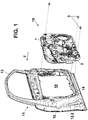
- Figure 1 shows as explosion view of a vehicle door (11) and the sealing device (10) of the invention.
- the vehicle door (11) comprises an upper window frame (13) and a door shell structure (12) having an outer sheet (12.1) facing the vehicle exterior joined to an inner sheet (12.2) facing the vehicle interior.
- the vehicle door (11) has a main opening (18) for mounting/dismounting the functional components and a first fixing hole (14) for connecting the sealing device (10) with the vehicle door (11).
- Both the main opening (18) and the first fixing hole (14) are placed in the inner sheet (12.2) of the vehicle door (11).
- the main opening (18) occupies a large portion of the surface of the inner sheet (12.2) in order to access easily to the interior of the door shell structure (12) for carrying out the mounting/dismounting operations of the functional components housed inside the door shell structure (12) such as the window regulator, the loudspeaker or the door lock.
- the first fixing hole (14) is configured to allow the connection between the sealing device (10) and the vehicle door (11) by inserting the fixing means (3) through it, and then by retaining said fixing means (3) in a final mounting position.
- Said first fixing hole (14) has a thickness e 3 .
- said first fixing hole (14) is non-circular mounting hole with a length l 1 and a width w 1 .
- Said first fixing hole (14) allows the retention of the fixing means (3) in the particular case it is a quarter turn clip (3) described in detail below, when it is rotated 90°.
- a sealing device (10) covering the main opening (14). It creates a barrier against water/dust between the wet area W and the dry area D of the vehicle door (11).
- the sealing device (10) is configured to be mounted on the vehicle door (11) along a mounting direction F in order to adopt a final mounting position in which the sealing device (10) and the vehicle door (11) are connected. In this final mounting position, the sealing device (10) divides the vehicle door (11) into the wet area W and the dry area D.
- the mounting direction F is essentially perpendicular to the main surface of the sealing device (10) and coincides with the direction of the main axle z of the fixing means (3).
- the sealing device (10) comprises three main components: a panel (1), a sealing strip (2) and a fixing means (3) for connecting the sealing device (10) and the vehicle door (11) according to a simple way.
- the panel (1) is configured to cover the main opening (18) of the vehicle door (11) in order to contribute to fulfil the sealing function.
- the panel (1) is made of plastic foam with a closed-cell structure.
- the plastic foam closed-cell structure can be formed by closed-cell foam beads.
- This panel (1) is mainly characterized by having a high elasticity and a high capacity to absorb energy.
- the panel (1) has a compressive strength along the mounting direction F which coincides with the direction of the thickness of said panel (1), less than 1000 KPa at 25% strain measured according to ISO844 and greater than 150 KPa at 25% strain measured according to ISO844.
- the panel (1) is deformed along the mounting direction F taking into account the forces exerted along the mounting direction F by the fixing means (3) on the panel (1) when the sealing device (10) is connected with the vehicle door (11) in the final mounting position.
- the panel (1) is characterized by its self-supporting properties, that is, it is able to support its own weight and the weight of other components attached to it keeping its shape, during the handling and mounting operations, and once it is mounted on the vehicle door.
- the panel (1) has an average density between 40 and 60 kg/m 3 .
- the low density of the panel (1) results in a low weight panel (1).
- the density of the panel (1) is the same along the direction of the thickness of said panel (1) in such a way that at any given point of the panel (1), the density of the core is the same than the density of the surface of the panel (1). It does not mean that the density at one point of the panel (1) is the same than the density at other point, it will depend on how compressed the material of panel (1) is at each point.
- This feature contributes to simplify the manufacturing process of the panel (1) and consequently to reduce its cost.
- panel (1) materials can be EPP (expanded polypropylene) or EPS (expanded polystyrene).
- the manufacturing process of the panel (1) comprises the injection of foam beads, for example EPP foam beads or EPS foam beads, into a mould. Then pressure and steam heat, for example by water vapour, are applied in order to expand and fuse the foam beads into a finished shape according to the shape of the mould.
- foam beads for example EPP foam beads or EPS foam beads
- the panel (1) has a first side (1.1) and a second side (1.2) opposite to the first side (1.1), which define the main surfaces of the panel (1). Particularly the first side (1.1) faces to the vehicle interior, and the second side (1.2) faces to the vehicle exterior.
- the surface corresponding to the second side (1.2) has a surface finishing (not represented) wherein the voids existing among surface cells of the panel (1) are sealed.
- Said surface finishing can be obtained for example, by a specific treatment of the surface of the mould in contact with the second side (1.2) of the panel (1) during its manufacturing process.
- the panel (1) has a second fixing hole (1.3) extended through the panel (1) from the first side (1.1) to the second side (1.2).
- This second fixing hole (1.3) houses at least a part of the fixing means (3) as explained later.
- the second fixing hole (1.3) has a thickness e 1 .
- said second fixing hole (1.3) with the fixing means (3) housed inside it is aligned with the first fixing hole (14) of the vehicle door (11) along the mounting direction F, in order to carry out the connection between the sealing device (10) and the vehicle door (11) for adopting the final mounting position.
- the second element which forms part of the sealing device (10) is the sealing strip (2).
- the sealing strip (2) comprises a hollow profile, although other geometries could be possible.
- the ratio between the main dimension m 1 of the sealing strip (2) along the mounting direction F when said sealing strip (2) is not compressed and the main dimension m 2 of the sealing strip (2) along the mounting direction F when it is not compressed is in the range between 1.75 and 2.5.
- the sealing strip (2) can be configured as a closed loop.
- the sealing strip (2) can be integrated with the panel (1) that is, it can be formed from the same material and at the same time than the panel (1).
- the sealing strip (2) is configured as an additional component applied on the second side (1.2) of the panel (1).
- the sealing strip (2) can be applied for example by extrusion.
- junction (not represented) between the ends of the sealing strip (2) is formed.
- This junction is designed to be on the upper part of the panel (1) wherein there is no risk to stagnant water.
- the sealing strip (2) for example can be made of thermoplastic elastomer (TPE), and preferably a thermoplastic vulcanisates (TPV).
- TPE thermoplastic elastomer
- TPV thermoplastic vulcanisates
- the last essential component which configures the sealing device (10) is the fixing means (3).
- This fixing means (3) are considered the first fixing means since that later on the description other different fixing means are described.
- the fixing means (3) comprise a main axle z extended along the mounting direction F, a retention wing (3.1) placed on a first side (1.1) of the panel (1) and configured to retain the fixing means (3) in the second fixing hole (1.3) of the panel (1), due to the interference between the retention wing (3.1) and the first side (1.1) of the panel (1) around the second fixing hole (1.3), an attaching head (3.4) placed on a second side (1.2) of the panel (1), and a cylindrical body (3.2) connected to the retention wing (3.1) and housed in the second fixing hole (1.3) of the panel (1).
- the sealing device (10) can comprises one or several fixing means (3) along the contour of the panel (1) as for example it is shown in figure 1 .
- the fixing means (3) are located close to the sealing strip (2) and they are uniformly distributed in order to ensure a homogenous compression along its length.
- the fixing means (3) can comprise a quarter turn clip (3).
- the quarter turn clip (3) comprises:
- the cylindrical body (3.2) has a diameter bigger than the diameter of the second fixing hole (1.3) of the panel (1) in such a way that when the cylindrical body (3.2) is inside the second fixing hole (1.3) they elastically fit together.
- the attaching head (3.4) is configured to adopt two positions, a first position in which the attaching head (3.4) can pass through the first fixing hole (14) of the vehicle door (11) and a second position that coincides with the final mounting position in which the attached head (3.4) is rotated with respect to the first position, and in which the attaching head (3.4) is retained within the first fixing hole (14) of the vehicle door (11).
- the cross section of the attaching head has a length l 2 and a width w 2 smaller than the corresponding length l 1 and width l 2 of said first fixing hole (14), as shown in figure 9 .
- the separation distance h 1 between the first plane p 1 and the second plane p 2 is smaller than the thickness e 1 of the second fixing hole (1.3) as shown in figure 9 .
- the sealing device (10) optionally can comprise other functional components typically mounted on a vehicle door (11) such as a loudspeaker (5), a window regulator (4), a padding (16), door handle (not represented), electric wiring (8) or the airbag sensor (7).
- the third attachment means (15) can comprise for example screws as shown in figure 10 .
- the frame (19) is preferably made of plastic material designed to support the efforts mentioned above.
- the frame (19) is connected to the panel (1) by second attachment means (9) and optionally it can also be connected with the vehicle door (11) in the final mounting position of the assembly by fourth attachment means (20).
- the second attachment means (9) can comprise preferably adhesive but other attaching means could be possible.
- the fourth attachment means (20) can comprise preferably screws but other attaching means could be possible.
- One example of a functional component which needs the presence of a frame (19) is the loudspeaker (5) .
- the loudspeaker (5) is sandwiched and compressed between the frame (19) and the panel (1) and it is directly fixed to the frame (19) by the third attachment means (15).
- This particular configuration allows the vibrations produced by the loudspeaker (5) during its normal use being absorbed by the panel (1).
- the panel (1) comprises a cavity (1.4) configured to house said electric motor (6).
- This particular configuration allows mainly two effects. On the one hand the vibrations produced by the electric motor (6) during its normal use are absorbed by the panel (1). On the other hand the sound produced by the electric motor (6) during its normal use is confined inside the cavity (1.4) covered by the decorative panel (21) in such a way that said sound is not perceived by the occupant of the vehicle.
- the window regulator (4) is fixed to the panel (1) by the second attachment means (9) and optionally can also be fixed to the door vehicle (11) in the final mounting position of the assembly by the fourth attachment means (20).
- the second attachment means (9) can comprise preferably adhesive but other attaching means could be possible.
- the fourth attachment means (20) can comprise preferably screws but other attaching means could be possible.
- the window regulator (4) can comprise one rail (4.1) or two rails (4.1) as figures 4 and 5 show.
- the window regulator (4) can be configured as a structural supporting element formed by two rails (4.1) connected each other by reinforced elements (4.2). Moreover the reinforced elements (4.2) can comprise supporting portions, as the frame (19), for fixing other functional components such as an electric motor (6).
- the reinforced elements (4.2) allow distributing the efforts generated during the window regulator (4) and/or other functional components operation through the whole component in order to transmit them to the vehicle door (11) by for example the fourth fixing means (20).
- the window regulator (4) can be made of plastic material reinforced with additional reinforcing means such as fibrous material, or it can be reinforced by geometrical configurations, such as a ribbed configuration or an increased thickness thereof along its length, or a configuration with a cross section providing a greater moment of inertial along the direction of the efforts generated by the functional component.
- the frame (19) for fixing the loudspeaker (5) can be formed as integral part of the window regulator (4).
- the frame (19) for fixing the electric motor (6) can be formed as integral part of the window regulator (4).
- the window regulator (4) is configured as an autonomous structural supporting element, that is, as an element capable of supporting the efforts generated due to the operation of the window regulator (4) and/or other functional components.
- the embodiment in which the window regulator (4) is also fixed to the vehicle door (11) by the fourth fixing means (20), as it is represented in figure 11 , has significant advantages over the configuration in which the window regulator (4) is only attached to the panel (1).
- the panel (1) is fixed to the vehicle door (11) by the fixing means (3), and on the other hand the window regulator (4) is fixed to the vehicle door (11) by the fourth fixing means (20).
- sealing device (10) can comprise other functional components such as the interior pull handle attachments (17) as it is shown in figure 5 and the airbag sensor (7) as it is shown in figure 4 .
- Said components (7, 17) can be connected to the frame (19) or to the window regulator (4) in the case in which the frame (19) forms an integral part of the window regulator (4).
- sealing device (10) can comprises other functional components such as the padding (16) for passive safety, or the channels (1.5) for housing the electric wiring (8).
- Said components (16, 1.5) are integrated with the panel (1).
- the panel (1) Due to the high elasticity of the panel (1) resulting in a high capacity of absorbing energy, the panel (1) allows absorbing the energy produced in the event of a lateral impact for the occupant protection allowing the configuration of the padding as an integral part of the panel (1) as figure 4 shows.
- the padding (16) can be formed by hollow cavities having different shapes.
- the padding (16) has a honeycomb structure, however the invention is not limited to said specific configuration.
- the panel (1) also comprises channels (1.5) for encapsulating tightly the electric wiring (8) due to the channels comprise several walls for limiting the movement of the electric wiring (8) in all the possible directions.
- the configuration of the channels (1.5) avoids the generation of noises due to the lack of gaps between the panel (1) and the electric wiring (8).
Landscapes
- Engineering & Computer Science (AREA)
- Mechanical Engineering (AREA)
- Seal Device For Vehicle (AREA)
Abstract
Description
- The present invention relates to a sealing device for vehicle doors having three main components, an elastic panel made of plastic foam with a closed-cell structure, a sealing strip placed along the perimeter of the panel, and fixing means for connecting the sealing device and the vehicle door ensuring the sealing function of the sealing device according to a simple way.
- The vehicle door typically comprises an upper window frame and a door shell structure having an outer sheet facing the vehicle exterior joined to an inner sheet facing the vehicle interior.
- The door shell structure houses several door functional components such as the window regulator, the loudspeaker, or the door lock.
- In order to access the interior of the door shell structure for carrying out the mounting/dismounting operations of said functional components, the inner sheet comprises one or more access openings.
- In order to avoid the entrance of water and dust inside the vehicle interior through the door shell, sealing devices are commonly used for covering the different access openings provided in the inner sheet. The sealing device divides the vehicle door into a wet area and a dry area.
- The simplest known solution to performance said division comprises the use of a plastic film covering the one or more access openings which is fixed along the whole perimeter of the inner sheet of the door shell structure.
- The main advantages of this solution are the low weight and simplicity.
- However due to the lack of self-supporting properties of the plastic film, it is necessary to fix the plastic film along the whole perimeter of said film, for example by an adhesive strip, in order to avoid the entrance of water since that the sealing device has no consistency enough to compress itself against the vehicle door.
- Moreover due to the lack of self-supporting properties, the plastic film is difficult to manipulate during its mounting process and it does not allow the modular assembly of the plastic film with other functional components such as the window regulator, the electric wiring or the loudspeaker.
- In order to improve the functionality of the sealing device and its handling, it is known sealing devices formed by self-supporting panels with a higher rigidity than a plastic film. Said self-supporting panels in addition to fulfilling the sealing function, they also perform other additional functions associated with the vehicle door environment.
- For the purpose of keeping a reduce weight, said self-supporting panels have a low density and they are easily deformable, such as expanded polypropylene (EPP) or expanded polystyrene (EPS).
- This structure in addition to acting as a water/dust barrier, it acts as a thermal and acoustic insulation and a safety element due to the properties of the plastic foam.
- One known example to illustrate said kind of sealing devices is
DE4337468 . This patent discloses a sealing device formed by an expanded polypropylene panel that in addition to fulfill the above cited functions, low weight, insulation and safety, it also acts as a decorative element. - Others known examples are
DE10026100 andDE19937000 . These patents disclose sealing devices formed by expanded polypropylene or expanded polystyrene panel that in addition to fulfill the above cited functions, low weight, insulation and safety, they also act as a supporting elements for some of the door functional components commonly used in vehicle doors such as the window regulator, the electric wiring or the loudspeaker. - On the other hand, with the objective to enhance the mounting efficiency of the sealing device, it is desirable to use quick assembly fasteners for connecting the sealing device and the vehicle door.
- One known example disclosing the use of quick assembly fasteners is
EP1179451 . This patent discloses a decorative sealing device formed by expanded polypropylene panel that in addition to fulfill the above cited functions, it comprises quick assembly fasteners for connecting the sealing device and the vehicle door, particularly it comprises clips for connecting the sealing device to the vehicle door. - Said clips are attached to clip-holders which in turn are welded to the sealing device.
- This complex way of attaching the clips to the sealing device it is necessary due to the particular plastic foam structure with a low rigidity of the sealing device which it has not enough consistency by itself to support the clip in use and to ensure its correct operation.
- Therefore the mounting of this kind of quick assembly fasteners involves the use of additional elements complicating the component, its manufacturing and increasing its cost.
- The role of the fasteners in addition to being relevant to the mounting operations, it is very important in order to ensure the sealing function.
- The fasteners should ensure an optimal tension assembly in order to compress the sealing device against the door structure enough to avoid even a minimal entrance of water or dust.
- Taking the above explained into account, the clips disclosed in
EP1179451 cannot ensure an optimal tension assembly and therefore cannot ensure the sealing function due to this kind of clips requires that its length must be larger in order to allow its mounting. - Thus once the clip is introduced into the hole provided in the door structure, it cannot compress enough the sealing device against said door structure to ensure the sealing function.
- In view of the disadvantages mentioned above, the object of the invention is a sealing device for vehicle doors fulfilling several functions in addition to the sealing function such as thermal and acoustic insulation and a safety function, and at the same time it allows a simple mounting without adding additional components and ensuring at all times the sealing function.
- The present invention is established and characterised by the independent claim, while the dependent claims describe additional features thereof.
- Due to the closed-cell structure of the plastic foam of the panel the sealing device has waterproof properties. Therefore the sealing device forms a barrier dividing the door shell into a wet area and a dry area in such a way that it ensures the sealing function.
- Due to the low compressive strength of the plastic foam structure of the panel it has good elasticity properties. This means that the panel is deformable under the forces usually applied by the fixing means when the sealing device reaches the final mounting position on the vehicle door. It is because the compression exerted by the fixing means on the panel when the sealing device is in said final mounting position which in turn allows ensuring the tension assembly of the fixing means.
- Therefore the elasticity properties of the panel contribute to the mounting kinematics of the assembly.
- The panel is configured as a self-supporting panel. Self-supporting in the context of the invention means that the panel is capable of supporting its own weight and the weight of the functional components attached to it keeping its shape, during the handling and mounting operations and once it is mounted on the vehicle door.
- Due to the panel is a self-supporting panel, it allows an easy handling of the sealing device and it allows facilitating the assembly of the sealing device on the vehicle door.
- It is because the panel is consistent enough to ensure the sealing function in spite of having a limited number of punctual fixing means being capable of compressing the sealing strip against the perimeter of the main opening of the vehicle door in a continuous manner along the whole perimeter of the main opening.
- Due to the closed-cell structure of the plastic foam of the panel it has a low rate of thermal conductivity, therefore the sealing device is a good thermal insulation enhancing the energy efficiency of the vehicle.
- Moreover due to the closed-cell structure of the plastic foam of the panel, the sound does not pass through the plastic foam structure, therefore the sealing device is a good acoustic insulation.
- Due to the closed-cell structure of the plastic foam of the panel in combination with the low compressive strength of the panel, it has a high capacity of absorbing energy because it is capable to dissipate a high amount of energy through its cell foam structure.
- As a consequence of this, on the one hand the sealing device has a good impact resistance improving the passive safety in the event of side impact. On the other hand the sealing device is capable of absorbing the vibrations produced by the functional components such as the loudspeaker of the electric motor, when they are in use, improving the acoustical properties of the sealing device.
- Due to the low compressive strength of panel, it allows a tighten mounting of any functional components, such as electric wiring, window regulator, attached on the panel, preventing in this way the rattle between the panel and said functional components. It improves the acoustical behaviour of the whole door.
- On the one hand the special configuration and collaboration between the fixing means, the panel, and the sealing strip ensures the sealing function of the sealing device when it is assembled in the vehicle door.
- It is due to the forces exerted by the fixing means on the panel when it adopts the final mounting position in combination with the elasticity properties of the panel.
- Such forces result in the compression and the deformation along the mounting direction of both, the panel and the sealing strip, against the vehicle door. As a result of said compression and deformation of the panel, the thickness of the second fixing hole of the panel before reaching the final mounting position is greater than the thickness of the second fixing hole after reaching said final mounting position.
- Therefore, the forces exerted by the fixing means apart from achieving an optimal tension assembly of the fixing means against the door structure, they ensure the sealing function of both, the whole assembly, due to the compression of the sealing strip against the door structure, and the second fixing hole of the panel, due to the compression of the material around said second fixing hole against the door structure.
- On the other hand, due to the fact that the fixing means are specially configured to be housed in the second fixing hole of the panel, such that the retention wing is placed on a first side of the panel retaining the fixing means in the mounting direction, and an attaching head is placed on a second side of the panel, the fixing means have enough support throughout the thickness of the panel to perform its retention function between the sealing device and the vehicle door without any additional reinforcing elements around the area where the fixing means are mounted even taking into account the high elasticity of the panel.
- This simplifies the configuration of the sealing device, its manufacturing process, its assembly on the door and consequently its cost.
- Optionally, in the case of the fixing means are a quarter turn clip, the process for connecting the sealing device and the door structure is quick and simple.
- This process comprises positioning the sealing device against the vehicle door, the introduction of the attaching head of every quarter turn clip through and the first fixing hole of the vehicle door, and then rotating 90° every quarter turn clip in order to carry out the connection between the sealing device and the vehicle door.
- In the optional case in which the diameter of the second fixing hole of the panel is smaller than the diameter of the cylindrical body of the quarter turn clip housed inside it, it results in a deformation of the material of the wall of the hole of the panel in such a way that the cylindrical body of the quarter turn clip and the wall of the second fixing hole of the panel elastically fit together.
- Thus, the second fixing hole of the panel is completely sealed, both axially and radially, without using additional elements.
- The present specification is completed by a set of figures that illustrate a preferred embodiment and in no way limit the invention.
-
Figure 1 shows an explosion view of the assembly formed by the vehicle door and the sealing device. -
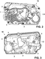
Figure 2 shows a front view of the first side of the sealing device according to a first embodiment of the invention. -
Figure 3 shows a front view of the second side of the sealing device according to a first embodiment of the invention. -
Figure 4 shows a front view of the first side of the sealing device according to a second embodiment of the invention. -
Figure 5 shows a front view of the second side of the sealing device according to a second embodiment of the invention. -
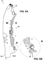
Figure 6A shows a lateral view of the assembly offigure 1 according to a pre-mounting position of the sealing device on the door structure. -
Figure 6B shows an enlarged detail A corresponding tofigure 6A of the area of the sealing strip. -
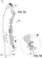
Figure 7A shows a lateral view of the assembly offigure 1 according to a final mounting position of the sealing device on the door structure. -
Figure 7B shows an enlarged detail B corresponding tofigure 7A of the area of the sealing strip wherein it is compressed against the vehicle door. -
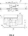
Figure 8 shows an explosion view of the quarter turn clip with the different planes orthogonal to the main axle, the panel, and the vehicle door. -
Figure 9 shows the different steps of the mounting process for connecting the panel and the vehicle door by the quarter turn clip. -
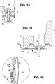
Figure 10 shows a detail view corresponding to a fixing point of the loudspeaker to the frame. -
Figure 11 shows a detail view corresponding to a fixing point of the window regulator to the vehicle door. -
Figure 12 shows a detail view corresponding to the housing of the panel for the electric motor. -
Figure 1 shows as explosion view of a vehicle door (11) and the sealing device (10) of the invention. - The vehicle door (11) comprises an upper window frame (13) and a door shell structure (12) having an outer sheet (12.1) facing the vehicle exterior joined to an inner sheet (12.2) facing the vehicle interior.
- The vehicle door (11) has a main opening (18) for mounting/dismounting the functional components and a first fixing hole (14) for connecting the sealing device (10) with the vehicle door (11).
- Both the main opening (18) and the first fixing hole (14) are placed in the inner sheet (12.2) of the vehicle door (11).
- The main opening (18) occupies a large portion of the surface of the inner sheet (12.2) in order to access easily to the interior of the door shell structure (12) for carrying out the mounting/dismounting operations of the functional components housed inside the door shell structure (12) such as the window regulator, the loudspeaker or the door lock.
- The first fixing hole (14) is configured to allow the connection between the sealing device (10) and the vehicle door (11) by inserting the fixing means (3) through it, and then by retaining said fixing means (3) in a final mounting position. Said first fixing hole (14) has a thickness e3.
- As
figure 9 shows, preferably said first fixing hole (14) is non-circular mounting hole with a length l1 and a width w1. Said first fixing hole (14) allows the retention of the fixing means (3) in the particular case it is a quarter turn clip (3) described in detail below, when it is rotated 90°. - In order to divide the vehicle door (11) into a wet area W and a dry area D, it is provided a sealing device (10) covering the main opening (14). It creates a barrier against water/dust between the wet area W and the dry area D of the vehicle door (11).
- The sealing device (10) is configured to be mounted on the vehicle door (11) along a mounting direction F in order to adopt a final mounting position in which the sealing device (10) and the vehicle door (11) are connected. In this final mounting position, the sealing device (10) divides the vehicle door (11) into the wet area W and the dry area D.
- The mounting direction F is essentially perpendicular to the main surface of the sealing device (10) and coincides with the direction of the main axle z of the fixing means (3). As it can be seen in
figures 2 and 3 , the sealing device (10) comprises three main components: a panel (1), a sealing strip (2) and a fixing means (3) for connecting the sealing device (10) and the vehicle door (11) according to a simple way. - Particularly the panel (1) is configured to cover the main opening (18) of the vehicle door (11) in order to contribute to fulfil the sealing function.
- The panel (1) is made of plastic foam with a closed-cell structure. Particularly the plastic foam closed-cell structure can be formed by closed-cell foam beads.
- This panel (1) is mainly characterized by having a high elasticity and a high capacity to absorb energy.
- Particularly the panel (1) has a compressive strength along the mounting direction F which coincides with the direction of the thickness of said panel (1), less than 1000 KPa at 25% strain measured according to ISO844 and greater than 150 KPa at 25% strain measured according to ISO844.
- According to the test method corresponding to ISO844, five 50x50x50 mm cubes are taken and compressed in an axial direction to the faces at a rate of 5 mm/min and at 25% strain. The compressive strength and corresponding relative deformation obtained are recorded.
- It allows that the panel (1) is deformed along the mounting direction F taking into account the forces exerted along the mounting direction F by the fixing means (3) on the panel (1) when the sealing device (10) is connected with the vehicle door (11) in the final mounting position.
- Therefore the elasticity properties of the panel (1) contribute to the mounting kinematics of the assembly.
- On the other hand, the panel (1) is characterized by its self-supporting properties, that is, it is able to support its own weight and the weight of other components attached to it keeping its shape, during the handling and mounting operations, and once it is mounted on the vehicle door.
- According to a preferred embodiment, the panel (1) has an average density between 40 and 60 kg/m3. The low density of the panel (1) results in a low weight panel (1).
- According to a preferred embodiment, the density of the panel (1) is the same along the direction of the thickness of said panel (1) in such a way that at any given point of the panel (1), the density of the core is the same than the density of the surface of the panel (1). It does not mean that the density at one point of the panel (1) is the same than the density at other point, it will depend on how compressed the material of panel (1) is at each point.
- This feature contributes to simplify the manufacturing process of the panel (1) and consequently to reduce its cost.
- Some examples for the panel (1) materials can be EPP (expanded polypropylene) or EPS (expanded polystyrene).
- According to a preferred embodiment the manufacturing process of the panel (1) comprises the injection of foam beads, for example EPP foam beads or EPS foam beads, into a mould. Then pressure and steam heat, for example by water vapour, are applied in order to expand and fuse the foam beads into a finished shape according to the shape of the mould.
- The panel (1) has a first side (1.1) and a second side (1.2) opposite to the first side (1.1), which define the main surfaces of the panel (1). Particularly the first side (1.1) faces to the vehicle interior, and the second side (1.2) faces to the vehicle exterior.
- Optionally, the surface corresponding to the second side (1.2) has a surface finishing (not represented) wherein the voids existing among surface cells of the panel (1) are sealed. Said surface finishing can be obtained for example, by a specific treatment of the surface of the mould in contact with the second side (1.2) of the panel (1) during its manufacturing process.
- Moreover the panel (1) has a second fixing hole (1.3) extended through the panel (1) from the first side (1.1) to the second side (1.2). This second fixing hole (1.3) houses at least a part of the fixing means (3) as explained later. The second fixing hole (1.3) has a thickness e1.
- During the mounting process, said second fixing hole (1.3) with the fixing means (3) housed inside it, is aligned with the first fixing hole (14) of the vehicle door (11) along the mounting direction F, in order to carry out the connection between the sealing device (10) and the vehicle door (11) for adopting the final mounting position.
- The second element which forms part of the sealing device (10) is the sealing strip (2).
- It is placed along the perimeter of the second side (1.2) of the panel (1), that is, along the contour of the panel (1) which is in contact with the perimeter of the vehicle door (11), and particularly of the inner sheet (12.2), around the main opening (18) when the sealing device (10) is connected with the vehicle door (11) according to the final mounting position.
- Preferably the sealing strip (2) comprises a hollow profile, although other geometries could be possible.
- In order to ensure the compression of the sealing strip (2) is enough to guarantee the sealing function in the final mounting position and at the same time to avoid the breaking of the sealing strip (2) due to an excessive compression, the ratio between the main dimension m1 of the sealing strip (2) along the mounting direction F when said sealing strip (2) is not compressed and the main dimension m2 of the sealing strip (2) along the mounting direction F when it is not compressed is in the range between 1.75 and 2.5.
- The sealing strip (2) can be configured as a closed loop.
- The sealing strip (2) can be integrated with the panel (1) that is, it can be formed from the same material and at the same time than the panel (1).
- However preferably, the sealing strip (2) is configured as an additional component applied on the second side (1.2) of the panel (1).
- The sealing strip (2) can be applied for example by extrusion.
- In this case a junction (not represented) between the ends of the sealing strip (2) is formed. This junction is designed to be on the upper part of the panel (1) wherein there is no risk to stagnant water.
- The sealing strip (2) for example can be made of thermoplastic elastomer (TPE), and preferably a thermoplastic vulcanisates (TPV).
- The last essential component which configures the sealing device (10) is the fixing means (3). This fixing means (3) are considered the first fixing means since that later on the description other different fixing means are described.
- They are configured to be housed inside the second fixing hole (1.3) of the panel (1) in order to connect the sealing device (10) and the vehicle door (11) to adopt a final mounting position.
- The fixing means (3) comprise a main axle z extended along the mounting direction F, a retention wing (3.1) placed on a first side (1.1) of the panel (1) and configured to retain the fixing means (3) in the second fixing hole (1.3) of the panel (1), due to the interference between the retention wing (3.1) and the first side (1.1) of the panel (1) around the second fixing hole (1.3), an attaching head (3.4) placed on a second side (1.2) of the panel (1), and a cylindrical body (3.2) connected to the retention wing (3.1) and housed in the second fixing hole (1.3) of the panel (1).
- The sealing device (10) can comprises one or several fixing means (3) along the contour of the panel (1) as for example it is shown in
figure 1 . - For the purpose of ensuring an appropriate compression of the sealing strip (2) preferably the fixing means (3) are located close to the sealing strip (2) and they are uniformly distributed in order to ensure a homogenous compression along its length.
- As
figure 8 shows, the fixing means (3) can comprise a quarter turn clip (3). - In this particular case, the quarter turn clip (3) comprises:
- the main axle z,
- the retention wing (3.1) configured to retain the quarter turn clip (3) in the second fixing hole (1.3) of the panel (1). It is configured to be placed on the first side (1.1) of the panel (1)
- the cylindrical body (3.2) connected to the retention wing (3.1) through a first plane p1 orthogonal to the main axle z. The cylindrical body (3.2) is configured to be housed inside of the second fixing hole (1.3) of the panel (1).
- Preferably the cylindrical body (3.2) has a diameter bigger than the diameter of the second fixing hole (1.3) of the panel (1) in such a way that when the cylindrical body (3.2) is inside the second fixing hole (1.3) they elastically fit together.
- a neck (3.3) connected to the cylindrical body (3.2),
- the attaching head (3.4). It is configured to be placed on the second side (1.2) of the panel (1) and it is insertable through the first fixing hole (14) of the vehicle door (1). The attaching head (3.4) is connected to the neck (3.3). The attaching head (3.4) has a main body (3.4.1) and two tension ramps (3.4.2) wherein the tension ramps (3.4.2) comprises a final mounting edge (3.4.2.1) in a second plane p2 orthogonal to the main axle z and parallel to the plane p1, and a starting mounting edge (3.4.2.2) in a third plane p3 orthogonal to the main axle z and parallel to the plane p1.
- As
figure 9 shows, the attaching head (3.4) is configured to adopt two positions, a first position in which the attaching head (3.4) can pass through the first fixing hole (14) of the vehicle door (11) and a second position that coincides with the final mounting position in which the attached head (3.4) is rotated with respect to the first position, and in which the attaching head (3.4) is retained within the first fixing hole (14) of the vehicle door (11). - In order to the attaching head (3.4) can pass through the first fixing hole (14), the cross section of the attaching head has a length l2 and a width w2 smaller than the corresponding length l1 and width l2 of said first fixing hole (14), as shown in
figure 9 . - In the final mounting position, a portion of the panel (1) around the second fixing hole (1.3) and the sealing strip (2) are compressed and deformed along the mounting direction F against the vehicle door (11) due to the action of the fixing means (3) in such a way that the thickness e1 of the second fixing hole (1.3) before the fixing means (3) adopt the final mounting position is greater than the thickness e2 of the second fixing hole (1.3) after the fixing means (3) adopt said final mounting position.
- In order to achieve this effect according to a particular case in which the fixing means (3) are a quarter turn clip (3), the separation distance h1 between the first plane p1 and the second plane p2 is smaller than the thickness e1 of the second fixing hole (1.3) as shown in
figure 9 . - As shown
figures 4 and 5 , in addition to the three main components (1, 2, 3) described above, the sealing device (10) optionally can comprise other functional components typically mounted on a vehicle door (11) such as a loudspeaker (5), a window regulator (4), a padding (16), door handle (not represented), electric wiring (8) or the airbag sensor (7). - Some of the functional components mentioned above need the presence of a frame (19) for supporting said functional components, that is an element capable of supporting the efforts produced during the operation of said functional components. For that, said functional components are connected to the frame (19) by third attachment means (15).
- The third attachment means (15) can comprise for example screws as shown in
figure 10 . - The frame (19) is preferably made of plastic material designed to support the efforts mentioned above.
- The frame (19) is connected to the panel (1) by second attachment means (9) and optionally it can also be connected with the vehicle door (11) in the final mounting position of the assembly by fourth attachment means (20).
- The second attachment means (9) can comprise preferably adhesive but other attaching means could be possible.
- The fourth attachment means (20) can comprise preferably screws but other attaching means could be possible.
- One example of a functional component which needs the presence of a frame (19) is the loudspeaker (5) .
- As
figure 10 shows, the loudspeaker (5) is sandwiched and compressed between the frame (19) and the panel (1) and it is directly fixed to the frame (19) by the third attachment means (15). - This particular configuration allows the vibrations produced by the loudspeaker (5) during its normal use being absorbed by the panel (1).
- So this particular configuration is particularly advantageous because it takes the advantages of the panel (1), due to its energy absorption capacity, and the advantages of the frame (19), due to efforts supporting capacity.
- Other example of a functional component which needs the presence of a frame (19) as the one described above, is the electric motor (6) for a window regulator (4) .
- As
figure 12 shows, the electric motor (6) is fixed directly to the frame (19). - Moreover the panel (1) comprises a cavity (1.4) configured to house said electric motor (6).
- In this way, once the decorative panel (21) is mounted on the vehicle door (11), the electric motor (6) is confined between the cavity (1.4) of the panel (1) and the decorative panel (21).
- This particular configuration allows mainly two effects. On the one hand the vibrations produced by the electric motor (6) during its normal use are absorbed by the panel (1). On the other hand the sound produced by the electric motor (6) during its normal use is confined inside the cavity (1.4) covered by the decorative panel (21) in such a way that said sound is not perceived by the occupant of the vehicle.
- Other functional component which can be added to the sealing device (10) is the window regulator (4).
- As it is represented in
figure 11 , the window regulator (4) is fixed to the panel (1) by the second attachment means (9) and optionally can also be fixed to the door vehicle (11) in the final mounting position of the assembly by the fourth attachment means (20). - The second attachment means (9) can comprise preferably adhesive but other attaching means could be possible.
- The fourth attachment means (20) can comprise preferably screws but other attaching means could be possible.
- The window regulator (4) can comprise one rail (4.1) or two rails (4.1) as
figures 4 and 5 show. - The window regulator (4) can be configured as a structural supporting element formed by two rails (4.1) connected each other by reinforced elements (4.2). Moreover the reinforced elements (4.2) can comprise supporting portions, as the frame (19), for fixing other functional components such as an electric motor (6).
- The reinforced elements (4.2) allow distributing the efforts generated during the window regulator (4) and/or other functional components operation through the whole component in order to transmit them to the vehicle door (11) by for example the fourth fixing means (20).
- The window regulator (4) can be made of plastic material reinforced with additional reinforcing means such as fibrous material, or it can be reinforced by geometrical configurations, such as a ribbed configuration or an increased thickness thereof along its length, or a configuration with a cross section providing a greater moment of inertial along the direction of the efforts generated by the functional component.
- According to an embodiment of the invention the frame (19) for fixing the loudspeaker (5) can be formed as integral part of the window regulator (4).
- According to other embodiment of the invention the frame (19) for fixing the electric motor (6) can be formed as integral part of the window regulator (4).
- Thus the window regulator (4) is configured as an autonomous structural supporting element, that is, as an element capable of supporting the efforts generated due to the operation of the window regulator (4) and/or other functional components.
- Then the efforts supported by the window regulator (4) are transmitted to the vehicle door (11).
- Said efforts can be transmitted directly to the vehicle door (11) in the case of the window regulator (4) is fixed to the vehicle door (11) by the fourth attachment means (20).
- Said efforts can also be transmitted to the vehicle door (11) indirectly by the panel (1), since the window regulator (4) is connected to the panel (1) by the second attachment means (9), and in turn the panel (1) is fixed to the vehicle door (11) by the fixing means (3).
- The embodiment in which the window regulator (4) is also fixed to the vehicle door (11) by the fourth fixing means (20), as it is represented in
figure 11 , has significant advantages over the configuration in which the window regulator (4) is only attached to the panel (1). - According this particular embodiment on the one hand the panel (1) is fixed to the vehicle door (11) by the fixing means (3), and on the other hand the window regulator (4) is fixed to the vehicle door (11) by the fourth fixing means (20).
- The fact to separate the fixing means for connecting each component (1, 4) to the vehicle door (11) allows that:
- The main function of the panel (1), that is the sealing function, it is particularly controlled due to the fixing means (3) are specially configured to fulfil this function due to the tension exerted by them in combination with the compression and the deformation of the panel (1).
- The main function of the window regulator (4) in the particular embodiment in which the functional components are connected to it, that is the structural function (the capacity to support and transmit the different efforts produced during the operation of the functional components), it is particularly controlled due to the fourth fixing means (20) are specially configured to fulfil this function due to they allow transmitting the efforts produced by the different functional components in use and the efforts produced during the operation of the window regulator (4) to the vehicle door (11).
- Therefore according to this configuration both functions can be combined in a single unit the sealing device (10) and being independently controlled.
- Additionally the sealing device (10) can comprise other functional components such as the interior pull handle attachments (17) as it is shown in
figure 5 and the airbag sensor (7) as it is shown infigure 4 . - Said components (7, 17) can be connected to the frame (19) or to the window regulator (4) in the case in which the frame (19) forms an integral part of the window regulator (4).
- Additionally the sealing device (10) can comprises other functional components such as the padding (16) for passive safety, or the channels (1.5) for housing the electric wiring (8).
- Said components (16, 1.5) are integrated with the panel (1).
- Due to the high elasticity of the panel (1) resulting in a high capacity of absorbing energy, the panel (1) allows absorbing the energy produced in the event of a lateral impact for the occupant protection allowing the configuration of the padding as an integral part of the panel (1) as
figure 4 shows. - The padding (16) can be formed by hollow cavities having different shapes.
- In the example shown in the
figure 5 , the padding (16) has a honeycomb structure, however the invention is not limited to said specific configuration. - As shown in
figure 4 , the panel (1) also comprises channels (1.5) for encapsulating tightly the electric wiring (8) due to the channels comprise several walls for limiting the movement of the electric wiring (8) in all the possible directions. - The configuration of the channels (1.5) avoids the generation of noises due to the lack of gaps between the panel (1) and the electric wiring (8).
Claims (20)
- Sealing device (10) for vehicle doors (11) having a main opening (18) and a first fixing hole (14), wherein the sealing device (10) is configured to be mounted on the vehicle door (11) along a mounting direction F, wherein the sealing device (10) comprises:a panel (1) made of plastic foam with a closed-cell structure and being self-supporting,the panel (1) is configured to cover the main opening (18) of the vehicle door (11),the panel (1) has a compressive strength along the mounting direction F less than 1000 KPa at 25% strain measured according to ISO844 and greater than 150 KPa at 25% strain measured according to ISO844,the panel (1) having a first side (1.1) and a second side (1.2) opposite to the first side (1.1) and a second fixing hole (1.3) extended through the panel (1) from the first side (1.1) to the second side (1.2) and having a thickness e1,a sealing strip (2) placed along the perimeter of the second side (1.2) of the panel (1),characterized in that the sealing device (10) further comprisesfixing means (3) configured for connecting the sealing device (10) and the vehicle door (11) having a main axle z extended along the mounting direction F, a retention wing (3.1) placed on a first side (1.1) of the panel (1), an attaching head (3.4) placed on a second side (1.2) of the panel (1) and a cylindrical body (3.2) connected to the retention wing (3.1) and housed in the second fixing hole (1.3) of the panel (1),wherein said fixing means (3) are configured to adopt a final mounting position in which the fixing means (3) connect the sealing device (10) and the vehicle door (11),wherein in the final mounting position a portion of the panel (1) around the second fixing hole (1.3) and the sealing strip (2) are compressed and deformed along the mounting direction F due to the action of the fixing means (3) in such a way that the thickness e1 of the second fixing hole (1.3) before the fixing means (3) adopt the final mounting position is greater than the thickness e2 of the second fixing hole (1.3) after the fixing means (3) adopt said final mounting position.
- Sealing device (10) for motor vehicle doors (11) according to claim 1 wherein the fixing means (3) are a quarter turn clip (3).
- Sealing device (10) for motor vehicle doors (11) according to claim 2 wherein the quarter turn clip (3) comprises:• the main axle z,• the retention wing (3.1) configured to retain the quarter turn clip (3) in the second fixing hole (1.3) of the panel (1) and configured to be placed on the first side (1.1) of the panel (1),• the cylindrical body (3.2) is connected to the retention wing (3.1) through a first plane p1 orthogonal to the main axle z,• a neck (3.3) connected to the cylindrical body (3.2),• the attaching head (3.4) is connected to the neck (3.3) and is insertable through the first fixing hole (14) of the vehicle door (11),wherein said attaching head (3.4) has a main body (3.4.1) and two tension ramps (3.4.2) wherein the tension ramps (3.4.2) comprise a final mounting edge (3.4.2.1) in a second plane p2 orthogonal to the main axle z and parallel to the plane p1, and a starting mounting edge (3.4.2.2) in a third plane p3 orthogonal to the main axle z and parallel to the plane p1,
and wherein the attaching head (3.4) is configured to adopt two positions, a first position in which the attaching head (3.4) is insertable through the first fixing hole (14) of the vehicle door (11) and a second position that coincides with the final mounting position, in which the attached head (3.4) is retainable within the first fixing hole (14) of the vehicle door (11) due to the rotation of the quarter turn clip (3) with respect to the first position. - Sealing device (10) for motor vehicle doors (11) according to claim 3 wherein the first plane p1 and the second plane p2 are separated a distance h1 smaller than the thickness e1 of the second fixing hole (1.3) of the panel (1).
- Sealing device (10) for motor vehicle doors (11) according to claim 1 wherein cylindrical body (3.2) has a diameter bigger than the diameter of the second fixing hole (1.3) of the panel (1) in such a way that when the cylindrical body (3.2) is inside the second fixing hole (1.3) they elastically fit together.
- Sealing device for motor vehicle door according to claim 1 wherein the panel (1) has an average density between 40 and 60 kg/m3.
- Sealing device (10) for motor vehicle doors (11) according to claim 1 wherein the density of the panel (1) at any given point of the panel (1) is the same along the direction of the thickness of the panel (1) in such a way that at any given point of the panel (1) the density of the core is the same than the density of the surface.
- Sealing device (10) for motor vehicle doors (11) according to claim 1 wherein the plastic foam with a closed-cell structure of the panel (1) is formed by closed-cell foam beads.
- Sealing device for motor vehicle doors according to claim 1 wherein the panel (1) is made of expanded polypropylene.
- Sealing device (10) for motor vehicle doors (11) according to claim 1 wherein the second side (1.2) of the panel (1) has a surface finishing wherein the voids existing among surface cells of the panel (1) are sealed.
- Sealing device (10) for motor vehicle doors (11) according to claim 1 wherein the sealing strip (2) forms a closed loop and has a hollow profile.
- Sealing device (10) for motor vehicle doors (11) according to claim 1 wherein the ratio between the main dimension of the sealing strip (2) along the mounting direction F when said sealing strip (2) is not compressed and when said sealing strip (2) is compressed is in the range between 1.75 and 2.5.
- Sealing device (10) for motor vehicle doors (11) according to claim 1 wherein the material sealing strip (2) is thermoplastic elastomer and wherein the sealing strip (2) is applied by extrusion on the second side (1.2) of the panel (1).
- Sealing device (10) for motor vehicle doors (11) according to claim 1 comprising a frame (19) for supporting functional components, wherein the frame (19) is connected with the panel (1).
- Sealing device (10) for motor vehicle doors (11) according to claim 14 wherein a loudspeaker (5) in fixed to the frame (19) in such a way that the panel (1) is sandwiched compressed between the frame (19) and the loudspeaker (5) in order to reduce the vibrations produced by the loudspeaker (5).
- Sealing device (10) for motor vehicle doors (11) according to claim 1 comprising window regulator (4) fixed to the panel (1).
- Sealing device (10) for motor vehicle doors (11) according to claim 16 wherein the window regulator (4) comprises a frame (19) for fixing the electric motor (6) of the window regulator (4).
- Sealing device (10) for motor vehicle doors (11) according to claim 1 comprising a frame (19) fixed to the panel (1) for supporting the loudspeaker (5) wherein the frame (19) is an integral part of a window regulator (4) and wherein the panel (1) is sandwiched and compressed between the frame (19) and the loudspeaker (5) in order to reduce the vibrations produced by the loudspeaker (5).
- Sealing device (10) for motor vehicle doors (11) according to claim 1 wherein the panel (1) comprises a cavity (1.4) configured to house tightly an electric motor (6) for a window regulator (4) in order to prevent vibrations produced by the electric motor (6) .
- Sealing device (10) for motor vehicle doors (11) according to claim 1 comprising a padding (16) integrated with the panel (1) for absorbing the energy produced in the event of a lateral impact.
Priority Applications (2)
| Application Number | Priority Date | Filing Date | Title |
|---|---|---|---|
| ES18382059T ES2845223T3 (en) | 2018-02-02 | 2018-02-02 | Sealing device for vehicle doors |
| EP18382059.6A EP3521075B1 (en) | 2018-02-02 | 2018-02-02 | Sealing device for vehicle doors |
Applications Claiming Priority (1)
| Application Number | Priority Date | Filing Date | Title |
|---|---|---|---|
| EP18382059.6A EP3521075B1 (en) | 2018-02-02 | 2018-02-02 | Sealing device for vehicle doors |
Publications (2)
| Publication Number | Publication Date |
|---|---|
| EP3521075A1 true EP3521075A1 (en) | 2019-08-07 |
| EP3521075B1 EP3521075B1 (en) | 2020-12-23 |
Family
ID=61168037
Family Applications (1)
| Application Number | Title | Priority Date | Filing Date |
|---|---|---|---|
| EP18382059.6A Not-in-force EP3521075B1 (en) | 2018-02-02 | 2018-02-02 | Sealing device for vehicle doors |
Country Status (2)
| Country | Link |
|---|---|
| EP (1) | EP3521075B1 (en) |
| ES (1) | ES2845223T3 (en) |
Cited By (2)
| Publication number | Priority date | Publication date | Assignee | Title |
|---|---|---|---|---|
| US11511610B2 (en) | 2018-11-12 | 2022-11-29 | Shape Corp. | Vehicle door carrier with integrated edge seal and method of manufacture |
| CN119218149A (en) * | 2023-06-30 | 2024-12-31 | 长城汽车股份有限公司 | A vehicle wading control method, system, storage medium and vehicle |
Citations (10)
| Publication number | Priority date | Publication date | Assignee | Title |
|---|---|---|---|---|
| DE4337468A1 (en) | 1992-11-13 | 1994-05-19 | Volkswagen Ag | Interior facing for vehicle door - comprises frame and inner part with sound insulation incorporates hard foam body as anti-crash structure |
| DE19914189A1 (en) * | 1999-03-24 | 2000-10-05 | Brose Fahrzeugteile | Connector for support section and metal sheet or frame of car door, is embedded, located and sealed by e.g. injected foam of support section, and turned through angle to grip behind sheet, locking it into position |
| DE19937000A1 (en) | 1999-08-03 | 2001-02-08 | Brose Fahrzeugteile | Support for holding functional units in a vehicle door is made of rigid foamed plastic |
| DE10026100A1 (en) | 2000-05-26 | 2001-11-29 | Illbruck Gmbh | Inner element for a motor vehicle door comprises at least on one side a layer of foam particles which have an open tubular shape |
| EP1179451A1 (en) | 2000-08-08 | 2002-02-13 | Sai Automotive Allibert Industrie | Vehicle door comprising a panel directly mounted on the structure of the door |
| KR20020056559A (en) * | 2000-12-29 | 2002-07-10 | 이계안 | a mounting structure of door trim for vehicles |
| WO2003037669A1 (en) * | 2001-10-31 | 2003-05-08 | Lear Corporation | Integrated door module |
| US20060261635A1 (en) * | 2005-05-23 | 2006-11-23 | Jay Winborn | Automobile door assemblies |
| US20100000156A1 (en) * | 2006-08-11 | 2010-01-07 | Thomas Salhoff | Unit carrier for fitting into a door structure of a motor vehicle door |
| US20170313165A1 (en) * | 2016-04-29 | 2017-11-02 | Magna Closures Inc. | Door assembly with collapsible carrier and water shield |
-
2018
- 2018-02-02 ES ES18382059T patent/ES2845223T3/en active Active
- 2018-02-02 EP EP18382059.6A patent/EP3521075B1/en not_active Not-in-force
Patent Citations (10)
| Publication number | Priority date | Publication date | Assignee | Title |
|---|---|---|---|---|
| DE4337468A1 (en) | 1992-11-13 | 1994-05-19 | Volkswagen Ag | Interior facing for vehicle door - comprises frame and inner part with sound insulation incorporates hard foam body as anti-crash structure |
| DE19914189A1 (en) * | 1999-03-24 | 2000-10-05 | Brose Fahrzeugteile | Connector for support section and metal sheet or frame of car door, is embedded, located and sealed by e.g. injected foam of support section, and turned through angle to grip behind sheet, locking it into position |
| DE19937000A1 (en) | 1999-08-03 | 2001-02-08 | Brose Fahrzeugteile | Support for holding functional units in a vehicle door is made of rigid foamed plastic |
| DE10026100A1 (en) | 2000-05-26 | 2001-11-29 | Illbruck Gmbh | Inner element for a motor vehicle door comprises at least on one side a layer of foam particles which have an open tubular shape |
| EP1179451A1 (en) | 2000-08-08 | 2002-02-13 | Sai Automotive Allibert Industrie | Vehicle door comprising a panel directly mounted on the structure of the door |
| KR20020056559A (en) * | 2000-12-29 | 2002-07-10 | 이계안 | a mounting structure of door trim for vehicles |
| WO2003037669A1 (en) * | 2001-10-31 | 2003-05-08 | Lear Corporation | Integrated door module |
| US20060261635A1 (en) * | 2005-05-23 | 2006-11-23 | Jay Winborn | Automobile door assemblies |
| US20100000156A1 (en) * | 2006-08-11 | 2010-01-07 | Thomas Salhoff | Unit carrier for fitting into a door structure of a motor vehicle door |
| US20170313165A1 (en) * | 2016-04-29 | 2017-11-02 | Magna Closures Inc. | Door assembly with collapsible carrier and water shield |
Cited By (2)
| Publication number | Priority date | Publication date | Assignee | Title |
|---|---|---|---|---|
| US11511610B2 (en) | 2018-11-12 | 2022-11-29 | Shape Corp. | Vehicle door carrier with integrated edge seal and method of manufacture |
| CN119218149A (en) * | 2023-06-30 | 2024-12-31 | 长城汽车股份有限公司 | A vehicle wading control method, system, storage medium and vehicle |
Also Published As
| Publication number | Publication date |
|---|---|
| ES2845223T3 (en) | 2021-07-26 |
| EP3521075B1 (en) | 2020-12-23 |
Similar Documents
| Publication | Publication Date | Title |
|---|---|---|
| US6447047B1 (en) | Vehicle door comprising a panel attached directly to the structure of the door | |
| JP7334334B2 (en) | Structural composite for battery housing | |
| US7198319B2 (en) | Door module for vehicle door | |
| US8950548B2 (en) | Broadband sound absorber | |
| US6197403B1 (en) | Integral sound absorber and water deflector door panel | |
| CN103158509B (en) | Shock absorber assembly | |
| JP7143738B2 (en) | Door wiring module | |
| JP6973624B2 (en) | Wiring member integrated built-in parts | |
| US9216630B2 (en) | Water shield | |
| JP3875974B2 (en) | Sound insulation sheet | |
| BRPI0808432A2 (en) | SAFE PEDESTRIAN AUTOMOTIVE CAP WITH REINFORCEMENT FOAM | |
| EP3521075B1 (en) | Sealing device for vehicle doors | |
| EP2695774A1 (en) | Sound-deadening sheet for automobile, method for manufacturing same, and automobile dash silencer using sound-deadening sheet | |
| US20030116993A1 (en) | Vehicle part and method of making same | |
| JP7424458B2 (en) | Door wiring module | |
| WO2001092063A1 (en) | Insert element for cavity sealing | |
| WO2007097278A1 (en) | Seal member for door | |
| JP6872924B2 (en) | Soundproofing material | |
| WO2020162147A1 (en) | Door wiring module and door wiring module production method | |
| JP6898773B2 (en) | Noise reduction member for fender | |
| US20050189789A1 (en) | Energy absorbing impact deflector for use in vehicle doors | |
| JP2013228043A (en) | Resin panel having sandwich structure | |
| KR101736805B1 (en) | Sandwich panel | |
| TWM606067U (en) | Withdrawable battery combination structure of bicycle | |
| CN211519430U (en) | Power assembly and vehicle with same |
Legal Events
| Date | Code | Title | Description |
|---|---|---|---|
| PUAI | Public reference made under article 153(3) epc to a published international application that has entered the european phase |
Free format text: ORIGINAL CODE: 0009012 |
|
| STAA | Information on the status of an ep patent application or granted ep patent |
Free format text: STATUS: THE APPLICATION HAS BEEN PUBLISHED |
|
| AK | Designated contracting states |
Kind code of ref document: A1 Designated state(s): AL AT BE BG CH CY CZ DE DK EE ES FI FR GB GR HR HU IE IS IT LI LT LU LV MC MK MT NL NO PL PT RO RS SE SI SK SM TR |
|
| AX | Request for extension of the european patent |
Extension state: BA ME |
|
| STAA | Information on the status of an ep patent application or granted ep patent |
Free format text: STATUS: REQUEST FOR EXAMINATION WAS MADE |
|
| 17P | Request for examination filed |
Effective date: 20200128 |
|
| RBV | Designated contracting states (corrected) |
Designated state(s): AL AT BE BG CH CY CZ DE DK EE ES FI FR GB GR HR HU IE IS IT LI LT LU LV MC MK MT NL NO PL PT RO RS SE SI SK SM TR |
|
| GRAP | Despatch of communication of intention to grant a patent |
Free format text: ORIGINAL CODE: EPIDOSNIGR1 |
|
| STAA | Information on the status of an ep patent application or granted ep patent |
Free format text: STATUS: GRANT OF PATENT IS INTENDED |
|
| INTG | Intention to grant announced |
Effective date: 20200708 |
|
| GRAS | Grant fee paid |
Free format text: ORIGINAL CODE: EPIDOSNIGR3 |
|
| GRAA | (expected) grant |
Free format text: ORIGINAL CODE: 0009210 |
|
| STAA | Information on the status of an ep patent application or granted ep patent |
Free format text: STATUS: THE PATENT HAS BEEN GRANTED |
|
| AK | Designated contracting states |
Kind code of ref document: B1 Designated state(s): AL AT BE BG CH CY CZ DE DK EE ES FI FR GB GR HR HU IE IS IT LI LT LU LV MC MK MT NL NO PL PT RO RS SE SI SK SM TR |
|
| REG | Reference to a national code |
Ref country code: GB Ref legal event code: FG4D |
|
| REG | Reference to a national code |
Ref country code: DE Ref legal event code: R096 Ref document number: 602018011089 Country of ref document: DE |
|
| REG | Reference to a national code |
Ref country code: AT Ref legal event code: REF Ref document number: 1347380 Country of ref document: AT Kind code of ref document: T Effective date: 20210115 |
|
| REG | Reference to a national code |
Ref country code: IE Ref legal event code: FG4D |
|
| PG25 | Lapsed in a contracting state [announced via postgrant information from national office to epo] |
Ref country code: GR Free format text: LAPSE BECAUSE OF FAILURE TO SUBMIT A TRANSLATION OF THE DESCRIPTION OR TO PAY THE FEE WITHIN THE PRESCRIBED TIME-LIMIT Effective date: 20210324 Ref country code: NO Free format text: LAPSE BECAUSE OF FAILURE TO SUBMIT A TRANSLATION OF THE DESCRIPTION OR TO PAY THE FEE WITHIN THE PRESCRIBED TIME-LIMIT Effective date: 20210323 Ref country code: RS Free format text: LAPSE BECAUSE OF FAILURE TO SUBMIT A TRANSLATION OF THE DESCRIPTION OR TO PAY THE FEE WITHIN THE PRESCRIBED TIME-LIMIT Effective date: 20201223 Ref country code: FI Free format text: LAPSE BECAUSE OF FAILURE TO SUBMIT A TRANSLATION OF THE DESCRIPTION OR TO PAY THE FEE WITHIN THE PRESCRIBED TIME-LIMIT Effective date: 20201223 |
|
| PGFP | Annual fee paid to national office [announced via postgrant information from national office to epo] |
Ref country code: FR Payment date: 20210226 Year of fee payment: 4 |
|
| REG | Reference to a national code |
Ref country code: AT Ref legal event code: MK05 Ref document number: 1347380 Country of ref document: AT Kind code of ref document: T Effective date: 20201223 |
|
| REG | Reference to a national code |
Ref country code: NL Ref legal event code: MP Effective date: 20201223 |
|
| PG25 | Lapsed in a contracting state [announced via postgrant information from national office to epo] |
Ref country code: BG Free format text: LAPSE BECAUSE OF FAILURE TO SUBMIT A TRANSLATION OF THE DESCRIPTION OR TO PAY THE FEE WITHIN THE PRESCRIBED TIME-LIMIT Effective date: 20210323 Ref country code: LV Free format text: LAPSE BECAUSE OF FAILURE TO SUBMIT A TRANSLATION OF THE DESCRIPTION OR TO PAY THE FEE WITHIN THE PRESCRIBED TIME-LIMIT Effective date: 20201223 Ref country code: SE Free format text: LAPSE BECAUSE OF FAILURE TO SUBMIT A TRANSLATION OF THE DESCRIPTION OR TO PAY THE FEE WITHIN THE PRESCRIBED TIME-LIMIT Effective date: 20201223 |
|
| PGFP | Annual fee paid to national office [announced via postgrant information from national office to epo] |
Ref country code: ES Payment date: 20210304 Year of fee payment: 4 Ref country code: DE Payment date: 20210225 Year of fee payment: 4 |
|
| PG25 | Lapsed in a contracting state [announced via postgrant information from national office to epo] |
Ref country code: HR Free format text: LAPSE BECAUSE OF FAILURE TO SUBMIT A TRANSLATION OF THE DESCRIPTION OR TO PAY THE FEE WITHIN THE PRESCRIBED TIME-LIMIT Effective date: 20201223 Ref country code: NL Free format text: LAPSE BECAUSE OF FAILURE TO SUBMIT A TRANSLATION OF THE DESCRIPTION OR TO PAY THE FEE WITHIN THE PRESCRIBED TIME-LIMIT Effective date: 20201223 |
|
| REG | Reference to a national code |
Ref country code: LT Ref legal event code: MG9D |
|
| REG | Reference to a national code |
Ref country code: ES Ref legal event code: FG2A Ref document number: 2845223 Country of ref document: ES Kind code of ref document: T3 Effective date: 20210726 |
|
| PG25 | Lapsed in a contracting state [announced via postgrant information from national office to epo] |
Ref country code: LT Free format text: LAPSE BECAUSE OF FAILURE TO SUBMIT A TRANSLATION OF THE DESCRIPTION OR TO PAY THE FEE WITHIN THE PRESCRIBED TIME-LIMIT Effective date: 20201223 Ref country code: RO Free format text: LAPSE BECAUSE OF FAILURE TO SUBMIT A TRANSLATION OF THE DESCRIPTION OR TO PAY THE FEE WITHIN THE PRESCRIBED TIME-LIMIT Effective date: 20201223 Ref country code: PT Free format text: LAPSE BECAUSE OF FAILURE TO SUBMIT A TRANSLATION OF THE DESCRIPTION OR TO PAY THE FEE WITHIN THE PRESCRIBED TIME-LIMIT Effective date: 20210423 Ref country code: SM Free format text: LAPSE BECAUSE OF FAILURE TO SUBMIT A TRANSLATION OF THE DESCRIPTION OR TO PAY THE FEE WITHIN THE PRESCRIBED TIME-LIMIT Effective date: 20201223 Ref country code: SK Free format text: LAPSE BECAUSE OF FAILURE TO SUBMIT A TRANSLATION OF THE DESCRIPTION OR TO PAY THE FEE WITHIN THE PRESCRIBED TIME-LIMIT Effective date: 20201223 Ref country code: CZ Free format text: LAPSE BECAUSE OF FAILURE TO SUBMIT A TRANSLATION OF THE DESCRIPTION OR TO PAY THE FEE WITHIN THE PRESCRIBED TIME-LIMIT Effective date: 20201223 Ref country code: EE Free format text: LAPSE BECAUSE OF FAILURE TO SUBMIT A TRANSLATION OF THE DESCRIPTION OR TO PAY THE FEE WITHIN THE PRESCRIBED TIME-LIMIT Effective date: 20201223 |
|
| PG25 | Lapsed in a contracting state [announced via postgrant information from national office to epo] |
Ref country code: PL Free format text: LAPSE BECAUSE OF FAILURE TO SUBMIT A TRANSLATION OF THE DESCRIPTION OR TO PAY THE FEE WITHIN THE PRESCRIBED TIME-LIMIT Effective date: 20201223 Ref country code: AT Free format text: LAPSE BECAUSE OF FAILURE TO SUBMIT A TRANSLATION OF THE DESCRIPTION OR TO PAY THE FEE WITHIN THE PRESCRIBED TIME-LIMIT Effective date: 20201223 |
|
| REG | Reference to a national code |
Ref country code: DE Ref legal event code: R097 Ref document number: 602018011089 Country of ref document: DE |
|
| PG25 | Lapsed in a contracting state [announced via postgrant information from national office to epo] |
Ref country code: IS Free format text: LAPSE BECAUSE OF FAILURE TO SUBMIT A TRANSLATION OF THE DESCRIPTION OR TO PAY THE FEE WITHIN THE PRESCRIBED TIME-LIMIT Effective date: 20210423 Ref country code: MC Free format text: LAPSE BECAUSE OF FAILURE TO SUBMIT A TRANSLATION OF THE DESCRIPTION OR TO PAY THE FEE WITHIN THE PRESCRIBED TIME-LIMIT Effective date: 20201223 |
|
| REG | Reference to a national code |
Ref country code: BE Ref legal event code: MM Effective date: 20210228 |
|
| PG25 | Lapsed in a contracting state [announced via postgrant information from national office to epo] |
Ref country code: LU Free format text: LAPSE BECAUSE OF NON-PAYMENT OF DUE FEES Effective date: 20210202 Ref country code: LI Free format text: LAPSE BECAUSE OF NON-PAYMENT OF DUE FEES Effective date: 20210228 Ref country code: IT Free format text: LAPSE BECAUSE OF FAILURE TO SUBMIT A TRANSLATION OF THE DESCRIPTION OR TO PAY THE FEE WITHIN THE PRESCRIBED TIME-LIMIT Effective date: 20201223 Ref country code: CH Free format text: LAPSE BECAUSE OF NON-PAYMENT OF DUE FEES Effective date: 20210228 Ref country code: AL Free format text: LAPSE BECAUSE OF FAILURE TO SUBMIT A TRANSLATION OF THE DESCRIPTION OR TO PAY THE FEE WITHIN THE PRESCRIBED TIME-LIMIT Effective date: 20201223 |
|
| PLBE | No opposition filed within time limit |
Free format text: ORIGINAL CODE: 0009261 |
|
| STAA | Information on the status of an ep patent application or granted ep patent |
Free format text: STATUS: NO OPPOSITION FILED WITHIN TIME LIMIT |
|
| PG25 | Lapsed in a contracting state [announced via postgrant information from national office to epo] |
Ref country code: DK Free format text: LAPSE BECAUSE OF FAILURE TO SUBMIT A TRANSLATION OF THE DESCRIPTION OR TO PAY THE FEE WITHIN THE PRESCRIBED TIME-LIMIT Effective date: 20201223 |
|
| 26N | No opposition filed |
Effective date: 20210924 |
|
| PG25 | Lapsed in a contracting state [announced via postgrant information from national office to epo] |
Ref country code: IE Free format text: LAPSE BECAUSE OF NON-PAYMENT OF DUE FEES Effective date: 20210202 |
|
| PG25 | Lapsed in a contracting state [announced via postgrant information from national office to epo] |
Ref country code: SI Free format text: LAPSE BECAUSE OF FAILURE TO SUBMIT A TRANSLATION OF THE DESCRIPTION OR TO PAY THE FEE WITHIN THE PRESCRIBED TIME-LIMIT Effective date: 20201223 |
|
| PG25 | Lapsed in a contracting state [announced via postgrant information from national office to epo] |
Ref country code: IS Free format text: LAPSE BECAUSE OF FAILURE TO SUBMIT A TRANSLATION OF THE DESCRIPTION OR TO PAY THE FEE WITHIN THE PRESCRIBED TIME-LIMIT Effective date: 20210423 |
|
| PG25 | Lapsed in a contracting state [announced via postgrant information from national office to epo] |
Ref country code: BE Free format text: LAPSE BECAUSE OF NON-PAYMENT OF DUE FEES Effective date: 20210228 |
|
| REG | Reference to a national code |
Ref country code: DE Ref legal event code: R119 Ref document number: 602018011089 Country of ref document: DE |
|
| GBPC | Gb: european patent ceased through non-payment of renewal fee |
Effective date: 20220202 |
|
| PG25 | Lapsed in a contracting state [announced via postgrant information from national office to epo] |
Ref country code: FR Free format text: LAPSE BECAUSE OF NON-PAYMENT OF DUE FEES Effective date: 20220228 |
|
| PG25 | Lapsed in a contracting state [announced via postgrant information from national office to epo] |
Ref country code: GB Free format text: LAPSE BECAUSE OF NON-PAYMENT OF DUE FEES Effective date: 20220202 Ref country code: DE Free format text: LAPSE BECAUSE OF NON-PAYMENT OF DUE FEES Effective date: 20220901 |
|
| REG | Reference to a national code |
Ref country code: ES Ref legal event code: FD2A Effective date: 20230327 |
|
| PG25 | Lapsed in a contracting state [announced via postgrant information from national office to epo] |
Ref country code: ES Free format text: LAPSE BECAUSE OF NON-PAYMENT OF DUE FEES Effective date: 20220203 |
|
| PG25 | Lapsed in a contracting state [announced via postgrant information from national office to epo] |
Ref country code: CY Free format text: LAPSE BECAUSE OF FAILURE TO SUBMIT A TRANSLATION OF THE DESCRIPTION OR TO PAY THE FEE WITHIN THE PRESCRIBED TIME-LIMIT Effective date: 20201223 |
|
| PG25 | Lapsed in a contracting state [announced via postgrant information from national office to epo] |
Ref country code: HU Free format text: LAPSE BECAUSE OF FAILURE TO SUBMIT A TRANSLATION OF THE DESCRIPTION OR TO PAY THE FEE WITHIN THE PRESCRIBED TIME-LIMIT; INVALID AB INITIO Effective date: 20180202 |
|
| PG25 | Lapsed in a contracting state [announced via postgrant information from national office to epo] |
Ref country code: MK Free format text: LAPSE BECAUSE OF FAILURE TO SUBMIT A TRANSLATION OF THE DESCRIPTION OR TO PAY THE FEE WITHIN THE PRESCRIBED TIME-LIMIT Effective date: 20201223 |
|
| PG25 | Lapsed in a contracting state [announced via postgrant information from national office to epo] |
Ref country code: MT Free format text: LAPSE BECAUSE OF FAILURE TO SUBMIT A TRANSLATION OF THE DESCRIPTION OR TO PAY THE FEE WITHIN THE PRESCRIBED TIME-LIMIT Effective date: 20201223 |
|
| PG25 | Lapsed in a contracting state [announced via postgrant information from national office to epo] |
Ref country code: TR Free format text: LAPSE BECAUSE OF FAILURE TO SUBMIT A TRANSLATION OF THE DESCRIPTION OR TO PAY THE FEE WITHIN THE PRESCRIBED TIME-LIMIT Effective date: 20201223 |