EP3520957A1 - Device for handling parts stored on pallets positionable in the vicinity of a machining centre - Google Patents
Device for handling parts stored on pallets positionable in the vicinity of a machining centre Download PDFInfo
- Publication number
- EP3520957A1 EP3520957A1 EP19154503.7A EP19154503A EP3520957A1 EP 3520957 A1 EP3520957 A1 EP 3520957A1 EP 19154503 A EP19154503 A EP 19154503A EP 3520957 A1 EP3520957 A1 EP 3520957A1
- Authority
- EP
- European Patent Office
- Prior art keywords
- pallet
- transfer
- uprights
- aisle
- gripper
- Prior art date
- Legal status (The legal status is an assumption and is not a legal conclusion. Google has not performed a legal analysis and makes no representation as to the accuracy of the status listed.)
- Granted
Links
- 238000003754 machining Methods 0.000 title description 6
- 239000000969 carrier Substances 0.000 claims abstract description 35
- 230000005540 biological transmission Effects 0.000 claims description 13
- 238000006073 displacement reaction Methods 0.000 claims description 13
- 230000000284 resting effect Effects 0.000 claims description 4
- 230000000295 complement effect Effects 0.000 claims description 3
- 210000000056 organ Anatomy 0.000 description 5
- 238000004519 manufacturing process Methods 0.000 description 2
- 229910000746 Structural steel Inorganic materials 0.000 description 1
- 238000005253 cladding Methods 0.000 description 1
- 230000001360 synchronised effect Effects 0.000 description 1
- 238000004804 winding Methods 0.000 description 1
Images


Classifications
-
- B—PERFORMING OPERATIONS; TRANSPORTING
- B23—MACHINE TOOLS; METAL-WORKING NOT OTHERWISE PROVIDED FOR
- B23Q—DETAILS, COMPONENTS, OR ACCESSORIES FOR MACHINE TOOLS, e.g. ARRANGEMENTS FOR COPYING OR CONTROLLING; MACHINE TOOLS IN GENERAL CHARACTERISED BY THE CONSTRUCTION OF PARTICULAR DETAILS OR COMPONENTS; COMBINATIONS OR ASSOCIATIONS OF METAL-WORKING MACHINES, NOT DIRECTED TO A PARTICULAR RESULT
- B23Q7/00—Arrangements for handling work specially combined with or arranged in, or specially adapted for use in connection with, machine tools, e.g. for conveying, loading, positioning, discharging, sorting
- B23Q7/10—Arrangements for handling work specially combined with or arranged in, or specially adapted for use in connection with, machine tools, e.g. for conveying, loading, positioning, discharging, sorting by means of magazines
- B23Q7/106—Arrangements for handling work specially combined with or arranged in, or specially adapted for use in connection with, machine tools, e.g. for conveying, loading, positioning, discharging, sorting by means of magazines with means to deliver a certain quantity
-
- B—PERFORMING OPERATIONS; TRANSPORTING
- B23—MACHINE TOOLS; METAL-WORKING NOT OTHERWISE PROVIDED FOR
- B23Q—DETAILS, COMPONENTS, OR ACCESSORIES FOR MACHINE TOOLS, e.g. ARRANGEMENTS FOR COPYING OR CONTROLLING; MACHINE TOOLS IN GENERAL CHARACTERISED BY THE CONSTRUCTION OF PARTICULAR DETAILS OR COMPONENTS; COMBINATIONS OR ASSOCIATIONS OF METAL-WORKING MACHINES, NOT DIRECTED TO A PARTICULAR RESULT
- B23Q7/00—Arrangements for handling work specially combined with or arranged in, or specially adapted for use in connection with, machine tools, e.g. for conveying, loading, positioning, discharging, sorting
- B23Q7/14—Arrangements for handling work specially combined with or arranged in, or specially adapted for use in connection with, machine tools, e.g. for conveying, loading, positioning, discharging, sorting co-ordinated in production lines
- B23Q7/1426—Arrangements for handling work specially combined with or arranged in, or specially adapted for use in connection with, machine tools, e.g. for conveying, loading, positioning, discharging, sorting co-ordinated in production lines with work holders not rigidly fixed to the transport devices
-
- B—PERFORMING OPERATIONS; TRANSPORTING
- B65—CONVEYING; PACKING; STORING; HANDLING THIN OR FILAMENTARY MATERIAL
- B65G—TRANSPORT OR STORAGE DEVICES, e.g. CONVEYORS FOR LOADING OR TIPPING, SHOP CONVEYOR SYSTEMS OR PNEUMATIC TUBE CONVEYORS
- B65G1/00—Storing articles, individually or in orderly arrangement, in warehouses or magazines
- B65G1/02—Storage devices
- B65G1/04—Storage devices mechanical
- B65G1/0407—Storage devices mechanical using stacker cranes
-
- B—PERFORMING OPERATIONS; TRANSPORTING
- B65—CONVEYING; PACKING; STORING; HANDLING THIN OR FILAMENTARY MATERIAL
- B65G—TRANSPORT OR STORAGE DEVICES, e.g. CONVEYORS FOR LOADING OR TIPPING, SHOP CONVEYOR SYSTEMS OR PNEUMATIC TUBE CONVEYORS
- B65G1/00—Storing articles, individually or in orderly arrangement, in warehouses or magazines
- B65G1/02—Storage devices
- B65G1/04—Storage devices mechanical
- B65G1/0464—Storage devices mechanical with access from above
-
- B—PERFORMING OPERATIONS; TRANSPORTING
- B65—CONVEYING; PACKING; STORING; HANDLING THIN OR FILAMENTARY MATERIAL
- B65G—TRANSPORT OR STORAGE DEVICES, e.g. CONVEYORS FOR LOADING OR TIPPING, SHOP CONVEYOR SYSTEMS OR PNEUMATIC TUBE CONVEYORS
- B65G1/00—Storing articles, individually or in orderly arrangement, in warehouses or magazines
- B65G1/02—Storage devices
- B65G1/04—Storage devices mechanical
- B65G1/06—Storage devices mechanical with means for presenting articles for removal at predetermined position or level
Definitions
- the invention relates to a device for handling parts stored on pallets positionable in the vicinity of a machining center.
- a handling device comprising a frame equipped with pallet carriers, a gripper, and a transfer system for the transfer of the parts to be processed between the handling device and the machining center, said chassis defining an enclosure comprising a central aisle lined laterally pallet carriers organized in rows and columns, the gripper comprising two uprights equipped with movable grippers mounted movably mounted up and down along said uprights, said amounts positionable at least in the central aisle being coupled to a drive system for moving the posts inside said enclosure along at least two axes orthogonal to each other, one of the axes corresponding to an axis parallel to the longitudinal axis of the central aisle,
- An object of the invention is to propose a device for handling parts of the aforementioned type whose design allows a compact device to be obtained without harming the simplicity of manufacture and use of such a device.
- the subject of the invention is a device for handling parts stored on pallets that can be positioned in the vicinity of a machining center, this handling device comprising a chassis equipped with pallet carriers, a gripper and a transfer system. for the transfer of workpieces between the handling device and the machining center, said frame defining an enclosure comprising a central aisle laterally bordered pallet carriers organized in rows and columns, the gripper comprising two uprights equipped with organs gripper facing mobile mounted up and down along said uprights, said uprights positionable at least in the central aisle being coupled to a drive system moving the uprights within said enclosure according to at least two orthogonal axes between them, one of the axes corresponding to an axis parallel to the longitudinal axis of the central aisle, characterized in that the transfer system comprises a transfer tray, mounted movably in a direction transverse to the longitudinal axis of the central aisle between a so-called inner zone, in which it is arranged inside the enclosure and is adapted to cooperate with the gripper, for the transfer of
- the design of the device provides a pallet loading / unloading area of the device which may be unique.
- the design of the device makes it possible to have a single transfer zone. This results in a simplicity of the device.
- the mechanical designs of the gripper and the transfer system make the entire device easy to manufacture.
- the pallet carriers are stationary inside the chamber defined by the frame.
- the pallet carriers have a top face on which a pallet is able to rest by its underside face, the top face of the pallet carriers being provided with recessed patterns or relief adapted to cooperate with complementary shape patterns adapted to be formed on the underside of the pallets positionable on the pallet carriers.
- This arrangement allows a safe and precise positioning of the pallets on the pallet carriers.
- the upright driving system comprises a frame, said horizontal, quadrangular mounted on the sliding frame in a direction parallel to the longitudinal axis of the central aisle, this frame housing a support to which the amounts are coupled, the support being slidably mounted along so-called transverse edges of the frame, these transverse edges of the frame extending orthogonally to the longitudinal axis of the central aisle.
- the movements of the drive system are thus only simple movements of translation.
- each upright comprises an endless transmission member and moving drive means of said endless transmission member, said endless transmission member having the shape of an endless loop with a strand going and a return strand of the loop extending parallel to the longitudinal axis of the upright, each gripping member equipping an amount being coupled to one of the strands of the loop.
- each gripping member equipping an amount affects the shape of a finger, a cleat or an angle L.
- This arrangement allows the pallets resting on the pallet carriers or the transfer tray to be gripped from below and the pallet carriers or the transfer tray to be placed on the top of the pallets, the pallets being dimensioned so as to extend to the pallet carrier. pallet carriers.
- the transfer plate is, for its displacement in a direction transverse to the longitudinal axis of the central aisle between the inner zone and the outer zone, slidably coupled to a support delimiting a guide path of the transfer plate, this support being mounted movably upward and downward relative to the frame.
- the transfer plate extends cantilever with respect to the guide path, in the position in which it is arranged in the outer zone.
- the support is a movable support in a direction orthogonal to the longitudinal axis of the central aisle to form with the transfer plate a telescopic assembly.
- This design allows unloading or easy loading of a pallet at the machining center using the transfer tray without affecting the travel path of said transfer tray.
- the transfer plate is, in the state arranged in the inner zone, configured to occupy at least a first position, in which it is arranged in the central aisle, and a second position. , in which it is arranged in one of the pallet-carrying areas bordering the central aisle.
- the piece handling device 1, object of the invention is more particularly intended to be positioned in the vicinity of a numerically controlled machining center 31, that is to say generally to less than 2 meters from the machining center, to allow the automatic movement of the workpieces stored on pallets 30 of the handling device to the machining center 31, and machined parts of the machining center 31 towards the center of machining. handling in the absence of any operator.
- This handling device 1 comprises a frame 2 equipped with pallet carrier 3, a gripper 4 and a transfer system 5 for the transfer of the parts to be treated, and in particular to be machined, between the handling device 1 and the center 31. 'machining.
- the frame 2 delimits an enclosure 6 of generally parallelepipedal shape comprising a central aisle 7 laterally lined stationary pallet carriers 3 housed inside the chamber 6 and organized in rows and columns.
- the frame 2 is a mechanically welded structure formed of superposed horizontal frames, kept spaced apart from each other by uprights arranged at the corners of the frames.
- the lower frames are interrupted to provide with two additional amounts a window within which the transfer system is housed.
- the enclosure 6 of the frame 2 is formed by the interior space of the frames. Cladding panels can be reported on the mechanically welded structure, in at least some locations of said structure.
- Each pallet carrier 3 which is in the form of a plate is attached to a so-called longitudinal side of the frame.
- the pallet carriers are fixed in rows of four pallet carriers to one of the longitudinal sides of each frame, and in rows of three or four pallet carriers to the other of the longitudinal sides of each frame .
- Three superposed frames are each equipped with two rows of pallet carriers.
- Each pallet holder 3 has a face 15 of the top on which a pallet 30 is able to rest by its so-called face. below in extending projecting from the face 15 of the top of the pallet holder 3.
- the face 15 of the top of the pallet carrier 3 is provided with recessed patterns 16, here cavities, able to cooperate with complementary patterns, such as pads, formed on the underside of pallets 30 positionable on the pallet carriers 3, the underside of these pallets forming the bearing face of the pallets on the pallet carriers.
- the top face of the pallet carriers could have been provided with patterns in relief, the underside of the pallets being provided with recessed patterns.
- the pads of the pallet 31 fit into the cavities of the pallet carrier, guaranteeing a precise and safe positioning of the pallet which is in form. a plate on the pallet holder.
- One of the pallet carriers forms a pallet loading station of the handling device 1.
- the operator thus positions each pallet to be treated on the pallet holder before this pallet is taken over by the gripper.
- the pallet gripper 4 comprises, in turn, two uprights 8 equipped with gripping members 17 facing each other, mounted movably upward and down along said uprights 8.
- the uprights 8, which can be positioned at least in the central aisle 7, are coupled to a 9 drive system for moving the uprights 8 inside said enclosure 6, along at least two axes XX ', YY' orthogonal to each other.
- One of the axes shown XX 'in the figures corresponds to an axis parallel to the longitudinal axis of the central aisle.
- the other axis shown in YY 'and said horizontal allows a displacement of the uprights 8 between one of the pallet carrier areas bordering laterally the central aisle and the other pallet carrier area bordering laterally the central year.
- each upright 8 comprises an endless transmission member 18 which may be formed by a chain or a belt and means 19 for driving the endless transmission member 18 on itself.
- These drive means 19 for moving the endless transmission member 18 are motor means 19.
- each upright comprises an upper pulley disposed at the upper end of the upright and a lower pulley disposed at the lower end of the upright, and an endless transmission member such as a chain or a belt winding at least partially around said pulleys, to form an endless loop with a strand 181 go and 182 return of the loop, extending parallel to the longitudinal axis of the upright 8.
- Each member 17 gripping equipping a post 8 is coupled to one of the strands 181 or 182 of the loop.
- the gripping members 17 are arranged at the same level from one upright to the next.
- the drive means 19 for driving the endless transmission member 18 comprise a motor driving one of the pulleys in rotation and consequently the endless transmission member at least partially wrapping around the pulleys. These displacement drive means 19 are common to the transmission members 18 of each of the uprights 8 to allow synchronous movement of the gripping members 17.
- Each gripping member 17 equipping an upright 8 has the shape of a finger, a cleat or an L-shaped angle iron.
- each gripping member 17 has the shape of an L-shaped bracket and a pallet 30 is adapted to rest by one of its edges on the horizontal branch of the L formed by the angle, as shown in FIG. figure 4 .
- the pallet 30 is of greater area than the pallet carrier or the transfer tray to protrude laterally from the top face of the pallet carrier or the transfer tray.
- the drive system 9 for moving the uprights 8 along the axes XX 'and YY' comprises meanwhile a quadrangular horizontal frame 10 mounted on the chassis 2 sliding in a direction parallel to the longitudinal axis of the aisle 7 .
- This frame 10 houses a support 11 to which the uprights 8 are coupled.
- This support 11 is slidably mounted along the transverse edges 100 of the frame 10, these transverse edges 100 of the frame 10 extending orthogonally to the longitudinal axis of the aisle 7 central.
- the support 11 is slidably mounted along the transverse edges 100 of the frame, via means 13 displacement drive motors comprising a motor equipped for example with a rotary pinion engaged with a rack of the support, the motor 10 being mounted on the chassis 2 to slide in a direction parallel to the longitudinal axis of the aisle 7 central, through the means 12 drive motors in displacement comprising, for example, a motor carried by the frame, this motor being equipped with a rotary pinion engaged with a rack arranged along one of the longitudinal sides of one of the frames constituting the frame.
- displacement drive motors comprising a motor equipped for example with a rotary pinion engaged with a rack of the support, the motor 10 being mounted on the chassis 2 to slide in a direction parallel to the longitudinal axis of the aisle 7 central, through the means 12 drive motors in displacement comprising, for example, a motor carried by the frame, this motor being equipped with a rotary pinion engaged with a rack arranged along one of the longitudinal sides of one of the frames constituting the frame.
- the motors of the driving means for moving the support and the frame are managed via a control unit comprising a man / machine interface.
- This control unit is generally also able to communicate with the machining center.
- the transfer system 5 comprises a transfer plate 14 mounted movably in a direction transverse to the longitudinal axis of the aisle 7, between an inner zone 24 in which it is disposed inside the enclosure 6 and is adapted to cooperate with the gripper 4 for the transfer of a pallet 30 between the gripper 4 and the transfer plate 14, and an outer zone 25 in which it is at least partially projecting outside the 6 and is able to deposit or remove a pallet 30 in the machining center 31.
- the machining center 31 comprises a table arranged to receive the pallets, this table being provided with studs projecting from the face of the top of the table on which the pallet can rest at the top of the table. state posed by the transfer tray. In the same way, this pallet placed on the studs can be taken by the transfer plate adapted to be inserted between the face of the top of the table supporting the pads and the pallet. The height of the pads is therefore greater than the thickness of the transfer tray.
- the transfer plate 14 is, for its displacement in a direction transverse to the longitudinal axis of the central aisle between the inner zone and the outer zone, slidably coupled to a support 20 delimiting a path 21 for guiding the plate 14. transfer.
- This support 20 is a movable support mounted to move up and down with respect to the frame 2 and in a direction orthogonal to the longitudinal axis of the aisle 7, to form with the transfer plate 14, a telescopic assembly.
- the support 20 is movably mounted in a direction orthogonal to the longitudinal axis of the central aisle, via motor means 23 disposed between the support 20 and a base of the support 20 secured to the frame.
- the base includes a movable portion and a fixed portion attached to the frame.
- the motor means 23 may comprise a motor carried by the mobile part of the base of the support 20, this motor being equipped with a rotating pinion engaged with a rack of the support 20 for a movement back and forth of the support 20 in one direction orthogonal to the longitudinal axis of the central aisle.
- the movable portion of the base is itself mounted movably upward and downward relative to the fixed portion of the base, by means 22 motor means disposed between the fixed and movable parts of the base.
- These motor means 22 may comprise a motor driving a ball screw, this motor being disposed on the fixed part of the base, the screw fitting into a bearing coupled to the movable part of the base.
- the transfer plate 14 which, for its displacement in a direction transverse to the longitudinal axis of the central aisle 7 between the inner zone 24 and the outer zone 25, is slidably coupled to the support 20, is equipped with 26 motor means sliding drive means arranged between the transfer plate 14 and the support 20.
- These motor means 26 may comprise a motor carried by the transfer plate 14, this motor comprising a rotary pinion engaged with a rack fitted to the support 20 , for a movement back and forth of the transfer plate 14 relative to the support 20.
- the drive means 23 drive displacement of the support 20 in a direction orthogonal to the longitudinal axis of the aisle 7, the means 22 drive motors moving up and down the support 20 relative to the chassis and the means 26 drive motors in sliding displacement of the transfer plate 14 relative to the support 20 all comprise a motor and an engine control unit.
- This control unit can be common to all the engines of the means 22, 26 and 23 engines.
- This control unit can also be common with the motor control unit of the means 12 and 13 drive motors moving the frame 10 and the holder 11 of the gripper.
- This control unit can comprise a man / machine interface to allow automated or manual management of the movements of the frame and the support of the gripper on the one hand, and the movements of the transfer tray and the support of the transfer system on the other hand. .
- This control unit also allows the management of the gripping bodies amounts and their displacement.
- the movements of the frame and the support of the gripper and the transfer tray and the support of the transfer system can be memorized and sensors can be provided to detect the presence of pallets on the pallet carriers or on the transfer tray .
- the transfer plate 14 is partially recessed, to give the plate the shape of a fork with parallel fingers.
- This transfer plate 14 extends cantilever with respect to the guide path 21 in the position in which it is disposed in the outer zone. In this cantilever position, the transfer plate 14 can extend plumb or near the machining center of the machining center.
- This transfer plate 14 is, in the state arranged in the interior zone 24, configured to occupy at least a first position in which it is arranged in the central aisle and a second position in which it is arranged in the first position. pallet carrier areas along the central aisle.
- the transfer tray may, in the state disposed in the inner zone 24, be configured to occupy only a position in which it is disposed in one of the pallet carrier areas bordering the central aisle.
- the uprights 8 of the gripper 4 are positionable, on the one hand on either side of the transfer plate 14, on the other hand on either side of any of the doors pallets to allow, by means of the gripping members 17 equipping said uprights 8, a grip from below a pallet 30 resting on the pallet carrier 3 or on the transfer tray 14 or a pallet 30 on the pallet carrier 3 or on the transfer tray 14.
- the gripping members 17 are supported from below on the parts of the projecting pallets pallet carriers or the transfer tray in the set state of a pallet on a pallet carrier or a transfer tray. The gripping members therefore bear on the underside of the pallets.
- the handling of a pallet for machining the workpiece carried by the pallet is as follows: the pallet and the associated part are positioned by an operator on a pallet carrier forming the loading station of the pallet. device.
- the uprights of the gripper are positioned on either side of the pallet holder and the gripping members are arranged under the pallet and driven in elevation to allow a grip from below the pallet.
- the pallet is raised to be removed from the pallet rack.
- the amounts of the gripper are driven on the move to return to the aisle and come to position at the transfer system.
- the amounts can then be arranged on either side of the transfer plate, by relative displacement of the amounts and the transfer plate.
- the pallet disposed above the transfer plate is then deposited on the transfer plate, by moving in the direction of a lowering of the gripping members equipping the uprights.
- the transfer tray and the associated pallet are driven outwardly of the enclosure, to the machining center where the pallet can be arranged in the machining center. Generally, the transfer tray returns inside the enclosure, during the machining phase.
- the transfer tray comes back to the pallet and is moved towards the interior of the chassis enclosure.
- the pallet can be taken from below by the gripping members of the gripper uprights, and be spread by lifting the transfer plate.
- the amounts of the transfer system are driven in displacement until they are positioned on either side of a pallet rack of the frame on which the pallet can be deposited.
- This pallet holder may be the same as that on which the pallet was initially deposited, or another pallet holder.
- a new handling cycle can begin.
Abstract
Dispositif (1) de manutention de pièces stockées sur palettes (30) positionnable au voisinage d'un centre (31) d'usinage, ce dispositif (1) de manutention comprenant un châssis (2) équipé de porte-palettes (3), un préhenseur (4) et un système (5) de transfert des pièces à traiter entre le dispositif (1) de manutention et le centre (31) d'usinage.Le châssis (2) délimite une enceinte (6) comprenant une allée (7) centrale bordée latéralement des porte-palettes (3), le préhenseur (4) comprend deux montants (8) équipés d'organes (17) de préhension en regard montés mobiles en monte et baisse le long desdits montants (8) et un système (9) d'entrainement en déplacement des montants (8) à l'intérieur de ladite enceinte (6) suivant au moins deux axes (XX', YY') orthogonaux entre eux, le système (5) de transfert comprend un plateau (14) monté mobile suivant une direction transversale à l'axe longitudinal de l'allée (7) centrale entre l'intérieur de l'enceinte (6) et l'extérieur de l'enceinte (6), et les montants (8) du préhenseur (4) sont positionnables d'une part, de part et d'autre du plateau (14) de transfert, d'autre part, de part et d'autre de l'un quelconque des porte-palettes (3).Device (1) for handling parts stored on pallets (30) positionable in the vicinity of a machining center (31), this handling device (1) comprising a chassis (2) equipped with pallet carriers (3), a gripper (4) and a system (5) for transferring the workpieces between the handling device (1) and the machining center (31). The frame (2) delimits an enclosure (6) comprising an aisle ( 7) central laterally edged pallet carriers (3), the gripper (4) comprises two uprights (8) equipped with members (17) gripping mounted movably mounts up and down along said uprights (8) and a system (9) for moving the uprights (8) inside said enclosure (6) along at least two axes (XX ', YY') orthogonal to each other, the transfer system (5) comprises a plate (14) movably mounted in a direction transverse to the longitudinal axis of the central aisle (7) between the inside of the enclosure (6) and the outside the enclosure (6), and the uprights (8) of the gripper (4) are positionable on the one hand, on both sides of the transfer plate (14), on the other hand, on the other hand, and on the other of any of the pallet carriers (3).
Description
L'invention concerne un dispositif de manutention de pièces stockées sur palettes positionnable au voisinage d'un centre d'usinage.The invention relates to a device for handling parts stored on pallets positionable in the vicinity of a machining center.
Elle concerne plus particulièrement un dispositif de manutention comprenant un châssis équipé de porte-palettes, un préhenseur, et un système de transfert pour le transfert des pièces à traiter entre le dispositif de manutention et le centre d'usinage, ledit châssis délimitant une enceinte comprenant une allée centrale bordée latéralement des porte-palettes organisés en lignes et en colonnes, le préhenseur comprenant deux montants équipés d'organes de préhension en regard montés mobiles en monte et baisse le long desdits montants, lesdits montants positionnables au moins dans l'allée centrale étant couplés à un système d'entrainement en déplacement des montants à l'intérieur de ladite enceinte suivant au moins deux axes orthogonaux entre eux, l'un des axes correspondant à un axe parallèle à l'axe longitudinal de l'allée centrale,It relates more particularly to a handling device comprising a frame equipped with pallet carriers, a gripper, and a transfer system for the transfer of the parts to be processed between the handling device and the machining center, said chassis defining an enclosure comprising a central aisle lined laterally pallet carriers organized in rows and columns, the gripper comprising two uprights equipped with movable grippers mounted movably mounted up and down along said uprights, said amounts positionable at least in the central aisle being coupled to a drive system for moving the posts inside said enclosure along at least two axes orthogonal to each other, one of the axes corresponding to an axis parallel to the longitudinal axis of the central aisle,
Un tel dispositif est connu comme l'illustre le brevet
Un but de l'invention est de proposer un dispositif de manutention de pièces du type précité dont la conception permet l'obtention d'un dispositif compact sans nuire à la simplicité de fabrication et d'utilisation d'un tel dispositif.An object of the invention is to propose a device for handling parts of the aforementioned type whose design allows a compact device to be obtained without harming the simplicity of manufacture and use of such a device.
À cet effet, l'invention a pour objet un dispositif de manutention de pièces stockées sur palettes positionnable au voisinage d'un centre d'usinage, ce dispositif de manutention comprenant un châssis équipé de porte-palettes, un préhenseur et un système de transfert pour le transfert des pièces à traiter entre le dispositif de manutention et le centre d'usinage, ledit châssis délimitant une enceinte comprenant une allée centrale bordée latéralement des porte-palettes organisés en lignes et en colonnes, le préhenseur comprenant deux montants équipés d'organes de préhension en regard montés mobiles en monte et baisse le long desdits montants, lesdits montants positionnables au moins dans l'allée centrale étant couplés à un système d'entrainement en déplacement des montants à l'intérieur de ladite enceinte suivant au moins deux axes orthogonaux entre eux, l'un des axes correspondant à un axe parallèle à l'axe longitudinal de l'allée centrale, caractérisé en ce que le système de transfert comprend un plateau, dit de transfert, monté mobile suivant une direction transversale à l'axe longitudinal de l'allée centrale entre une zone dite intérieure, dans laquelle il est disposé à l'intérieur de l'enceinte et est apte à coopérer avec le préhenseur, pour le transfert d'une palette entre le préhenseur et le plateau de transfert, et une zone dite extérieure, dans laquelle il fait au moins partiellement saillie à l'extérieur de l'enceinte, et est apte à déposer ou prélever une palette dans le centre d'usinage, et en ce que les montants du préhenseur sont positionnables d'une part, de part et d'autre du plateau de transfert, d'autre part, de part et d'autre de l'un quelconque des porte-palettes, pour permettre, à l'aide des organes de préhension équipant lesdits montants, une prise par le dessous d'une palette reposant sur le porte-palette ou sur le plateau de transfert, ou une pose d'une palette sur le porte-palette ou sur le plateau de transfert.For this purpose, the subject of the invention is a device for handling parts stored on pallets that can be positioned in the vicinity of a machining center, this handling device comprising a chassis equipped with pallet carriers, a gripper and a transfer system. for the transfer of workpieces between the handling device and the machining center, said frame defining an enclosure comprising a central aisle laterally bordered pallet carriers organized in rows and columns, the gripper comprising two uprights equipped with organs gripper facing mobile mounted up and down along said uprights, said uprights positionable at least in the central aisle being coupled to a drive system moving the uprights within said enclosure according to at least two orthogonal axes between them, one of the axes corresponding to an axis parallel to the longitudinal axis of the central aisle, characterized in that the transfer system comprises a transfer tray, mounted movably in a direction transverse to the longitudinal axis of the central aisle between a so-called inner zone, in which it is arranged inside the enclosure and is adapted to cooperate with the gripper, for the transfer of a pallet between the gripper and the transfer tray, and a so-called outer zone, in which it is at least partially projecting outside the enclosure, and is adapted to deposit or remove a pallet in the machining center, and in that the amounts of the gripper are positionable on the one hand, on both sides of the transfer tray, on the other hand, on the one hand and on the other other of any of the pallet carriers, to allow, with the aid of the gripping members equipping said uprights, a grip from below a pallet resting on the pallet holder or on the transfer tray, or a placing a pallet on the pallet holder or on the transfer tray.
La conception du dispositif permet de disposer d'une zone de chargement/déchargement en palettes du dispositif qui peut être unique. De même, la conception du dispositif permet de disposer d'une zone de transfert unique. Il en résulte une simplicité du dispositif. Enfin, les conceptions mécaniques du préhenseur et du système de transfert rendent l'ensemble du dispositif aisé à fabriquer.The design of the device provides a pallet loading / unloading area of the device which may be unique. Of even, the design of the device makes it possible to have a single transfer zone. This results in a simplicity of the device. Finally, the mechanical designs of the gripper and the transfer system make the entire device easy to manufacture.
Selon un mode de réalisation de l'invention, les porte-palettes sont stationnaires à l'intérieur de l'enceinte délimitée par le châssis.According to one embodiment of the invention, the pallet carriers are stationary inside the chamber defined by the frame.
Il en résulte une simplicité de mise en oeuvre pour l'opérateur dont la mission est de charger et décharger les palettes du dispositif.This results in a simplicity of implementation for the operator whose mission is to load and unload the pallets of the device.
Selon un mode de réalisation de l'invention, les porte-palettes présentent une face de dessus sur laquelle une palette est apte à reposer par sa face dite du dessous, la face du dessus des porte-palettes étant munie de motifs en creux ou en relief aptes à coopérer avec des motifs de forme complémentaires aptes à être ménagés sur la face du dessous des palettes positionnables sur les porte-palettes.According to one embodiment of the invention, the pallet carriers have a top face on which a pallet is able to rest by its underside face, the top face of the pallet carriers being provided with recessed patterns or relief adapted to cooperate with complementary shape patterns adapted to be formed on the underside of the pallets positionable on the pallet carriers.
Cette disposition permet un positionnement sûr et précis des palettes sur les porte-palettes.This arrangement allows a safe and precise positioning of the pallets on the pallet carriers.
Selon un mode de réalisation de l'invention, le système d'entrainement des montants comprend un cadre, dit horizontal, quadrangulaire monté sur le châssis à coulissement suivant une direction parallèle à l'axe longitudinal de l'allée centrale, ce cadre logeant un support auquel les montants sont couplés, ce support étant monté mobile à coulissement le long des bords dits transversaux du cadre, ces bords transversaux du cadre s'étendant orthogonalement à l'axe longitudinal de l'allée central.According to one embodiment of the invention, the upright driving system comprises a frame, said horizontal, quadrangular mounted on the sliding frame in a direction parallel to the longitudinal axis of the central aisle, this frame housing a support to which the amounts are coupled, the support being slidably mounted along so-called transverse edges of the frame, these transverse edges of the frame extending orthogonally to the longitudinal axis of the central aisle.
Les mouvements du système d'entrainement sont ainsi uniquement des mouvements simples de translation.The movements of the drive system are thus only simple movements of translation.
Selon un mode de réalisation de l'invention, chaque montant comprend un organe de transmission sans fin et des moyens d'entrainement en déplacement dudit organe de transmission sans fin, ledit organe de transmission sans fin affectant la forme d'une boucle sans fin avec un brin aller et un brin retour de la boucle s'étendant parallèlement à l'axe longitudinal du montant, chaque organe de préhension équipant un montant étant couplé à l'un des brins de la boucle.According to one embodiment of the invention, each upright comprises an endless transmission member and moving drive means of said endless transmission member, said endless transmission member having the shape of an endless loop with a strand going and a return strand of the loop extending parallel to the longitudinal axis of the upright, each gripping member equipping an amount being coupled to one of the strands of the loop.
Selon un mode de réalisation de l'invention, chaque organe de préhension équipant un montant affecte la forme d'un doigt, d'un taquet ou d'une cornière en L.According to one embodiment of the invention, each gripping member equipping an amount affects the shape of a finger, a cleat or an angle L.
Cette disposition permet une prise par le dessous des palettes reposant sur les porte-palettes ou le plateau de transfert et une pose par le dessus des palettes sur les porte-palettes ou sur le plateau de transfert, les palettes étant dimensionnées pour s'étendre au-delà des porte-palettes.This arrangement allows the pallets resting on the pallet carriers or the transfer tray to be gripped from below and the pallet carriers or the transfer tray to be placed on the top of the pallets, the pallets being dimensioned so as to extend to the pallet carrier. pallet carriers.
Selon un mode de réalisation de l'invention, le plateau de transfert est, pour son déplacement suivant une direction transversale à l'axe longitudinal de l'allée centrale entre la zone intérieure et la zone extérieure, couplé à coulissement à un support délimitant un chemin de guidage du plateau de transfert, ce support étant monté mobile en monte et baisse par rapport au châssis.According to one embodiment of the invention, the transfer plate is, for its displacement in a direction transverse to the longitudinal axis of the central aisle between the inner zone and the outer zone, slidably coupled to a support delimiting a guide path of the transfer plate, this support being mounted movably upward and downward relative to the frame.
À nouveau, la cinématique du plateau de transfert est simplifiée.Again, the kinematics of the transfer tray is simplified.
Selon un mode de réalisation de l'invention, le plateau de transfert s'étend en porte-à-faux par rapport au chemin de guidage, dans la position dans laquelle il est disposé dans la zone extérieure.According to one embodiment of the invention, the transfer plate extends cantilever with respect to the guide path, in the position in which it is arranged in the outer zone.
Il est ainsi possible d'atteindre un centre d'usinage positionné à écartement du dispositif de manutention.It is thus possible to reach a machining center positioned spaced from the handling device.
Selon un mode de réalisation de l'invention, le support est un support mobile suivant une direction orthogonale à l'axe longitudinal de l'allée centrale pour former avec le plateau de transfert un ensemble télescopique.According to one embodiment of the invention, the support is a movable support in a direction orthogonal to the longitudinal axis of the central aisle to form with the transfer plate a telescopic assembly.
Cette conception permet un déchargement ou un chargement aisé d'une palette au niveau du centre d'usinage à l'aide du plateau de transfert sans nuire à la course de déplacement dudit plateau de transfert.This design allows unloading or easy loading of a pallet at the machining center using the transfer tray without affecting the travel path of said transfer tray.
Selon un mode de réalisation de l'invention, le plateau de transfert est, à l'état disposé dans la zone intérieure, configuré pour occuper au moins une première position, dans laquelle il est disposé dans l'allée centrale, et une deuxième position, dans laquelle il est disposé dans l'une des zones porte-palettes bordant l'allée centrale.According to one embodiment of the invention, the transfer plate is, in the state arranged in the inner zone, configured to occupy at least a first position, in which it is arranged in the central aisle, and a second position. , in which it is arranged in one of the pallet-carrying areas bordering the central aisle.
L'invention sera bien comprise à la lecture de la description suivante d'exemples de réalisation, en référence aux dessins annexés dans lesquels :
- La
figure 1 représente une vue en perspective d'un dispositif de manutention conforme à l'invention, les montants du préhenseur étant disposés dans l'allée centrale au niveau du système de transfert. - La
figure 2 représente une vue de côté du dispositif de lafigure 1 , le système de transfert ayant été omis - La
figure 3 représente une vue de dessus d'un dispositif de manutention conforme à l'invention, les montants du préhenseur étant disposés dans l'allée centrale à une extrémité de l'allée ; - La
figure 4 représente une vue en perspective d'un préhenseur conforme à l'invention, une palette étant portée par les organes de préhension équipant les montants du préhenseur, - La
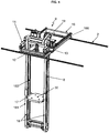
figure 5 représente une vue en perspective d'un système de transfert à l'état positionné du plateau de transfert à l'intérieur de l'enceinte ; - La
figure 6 représente une vue en perspective d'un système de transfert à l'état positionné du plateau de transfert au moins partiellement à l'extérieur de l'enceinte ; - La
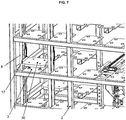
figure 7 représente une vue partielle en perspective d'un dispositif conforme à l'invention à l'état positionné des montants du préhenseur de part et d'autre d'un porte-palette et à l'état saisi d'une palette par les organes de préhension du préhenseur ; - La
figure 8 représente une vue partielle en perspective d'un dispositif conforme à l'invention à l'état positionné des montants du préhenseur de part et d'autre du plateau de transfert et à l'état saisi d'une palette par les organes de préhension du préhenseur ; - La
figure 9 représente une vue partielle en perspective d'un dispositif conforme à l'invention à l'état positionné du plateau de transfert en saillie de l'enceinte du châssis au-dessus d'une partie d'un centre d'usinage.
- The
figure 1 is a perspective view of a handling device according to the invention, the uprights of the gripper being disposed in the central aisle at the transfer system. - The
figure 2 represents a side view of the device of thefigure 1 , the transfer system having been omitted - The
figure 3 represents a top view of a handling device according to the invention, the uprights of the gripper being arranged in the central aisle at one end of the aisle; - The
figure 4 represents a perspective view of a gripper according to the invention, a pallet being carried by the gripping members equipping the gripper amounts, - The
figure 5 is a perspective view of a transfer system in the positioned state of the transfer tray inside the enclosure; - The
figure 6 is a perspective view of a transfer system in the positioned state of the transfer tray at least partially outside the enclosure; - The
figure 7 represents a partial perspective view of a device according to the invention in the positioned state of the gripper uprights on either side of a pallet holder and in the seized state of a pallet by the organs of grasping the gripper; - The
figure 8 represents a partial perspective view of a device according to the invention in the positioned state of the gripper uprights on either side of the transfer plate and in the gripped state of a pallet by the gripping members of the gripper; - The
figure 9 is a partial perspective view of a device according to the invention in the positioned state of the transfer plate projecting from the chassis enclosure above a portion of a machining center.
Comme mentionné ci-dessus, le dispositif 1 de manutention de pièce, objet de l'invention, est plus particulièrement destiné à être positionné au voisinage d'un centre 31 d'usinage à commande numérique, c'est-à-dire généralement à moins de 2 mètres du centre d'usinage, pour permettre le déplacement automatique des pièces à usiner stockées sur des palettes 30 du dispositif de manutention vers le centre 31 d'usinage, et des pièces usinées du centre 31 d'usinage vers le centre de manutention en l'absence de tout opérateur.As mentioned above, the piece handling
Ce dispositif 1 de manutention comprend un châssis 2 équipé de porte-palettes 3, un préhenseur 4 et un système 5 de transfert pour le transfert des pièces à traiter, et en particulier à usiner, entre le dispositif 1 de manutention et le centre 31 d'usinage.This
Le châssis 2 délimite une enceinte 6 de forme générale parallélépipédique comprenant une allée 7 centrale bordée latéralement des porte-palettes 3 stationnaires logés à l'intérieur de l'enceinte 6 et organisés en lignes et en colonnes.The
Dans l'exemple représenté, le châssis 2 est une structure mécanosoudée formée de cadres horizontaux superposés, maintenus à écartement les uns des autres par des montants disposés aux angles des cadres. Les cadres les plus inférieurs sont interrompus pour ménager à l'aide de deux montants supplémentaires une fenêtre à l'intérieur de laquelle le système 5 de transfert est logé.In the example shown, the
L'enceinte 6 du châssis 2 est donc formée par l'espace intérieur des cadres. Des panneaux d'habillage peuvent être rapportés sur la structure mécanosoudée, en au moins certains emplacements de ladite structure.The
Chaque porte-palette 3 qui se présente sous forme d'une plaque est fixé à un côté dit longitudinal du cadre. Dans l'exemple représenté, les porte-palettes sont fixés par rangée de quatre porte-palettes à l'un des côtés longitudinaux de chaque cadre, et par rangée de trois ou quatre porte-palettes à l'autre des côtés longitudinaux de chaque cadre. Trois cadres superposés sont équipés chacun de deux rangées de porte-palettes.Each
L'espace laissé libre entre les rangées de porte-palettes en regard forme l'allée 7 centrale du châssis 2. Chaque porte-palette 3 présente une face 15 du dessus sur laquelle une palette 30 est apte à reposer par sa face dite du dessous en s'étendant en saillie de la face 15 du dessus du porte-palette 3. La face 15 du dessus des porte-palettes 3 est munie de motifs 16 en creux, en l'occurrence ici des cavités, aptes à coopérer avec des motifs complémentaires, tels que des plots, ménagés sur la face du dessous de palettes 30 positionnables sur les porte-palettes 3, la face du dessous de ces palettes formant la face d'appui des palettes sur les porte-palettes. Bien évidemment, et de manière équivalente, la face du dessus des porte-palettes aurait pu être munie de motifs en relief, la face du dessous des palettes étant munie de motifs en creux.The space left between the rows of pallet carriers opposite forms the
Ainsi, à l'état posé d'une palette 31 sur un porte-palette 3, les plots de la palette 31 s'insèrent dans les cavités du porte-palette, garantissant un positionnement précis et sûr de la palette qui se présente sous forme d'une plaque sur le porte-palette.Thus, in the installed state of a
L'un des porte-palettes forme un poste de chargement en palettes du dispositif 1 de manutention. L'opérateur positionne ainsi chaque palette à traiter sur ce porte-palette avant que cette palette soit prise en charge par le préhenseur.One of the pallet carriers forms a pallet loading station of the
Le préhenseur 4 de palette comprend quant à lui deux montants 8 équipés d'organes 17 de préhension en regard, montés mobiles en monte et baisse le long desdits montants 8. Les montants 8 positionnables au moins dans l'allée 7 centrale sont couplés à un système 9 d'entraînement en déplacement des montants 8 à l'intérieur de ladite enceinte 6, suivant au moins deux axes XX', YY' orthogonaux entre eux.The
L'un des axes représentés en XX' aux figures correspond à un axe parallèle à l'axe longitudinal de l'allée centrale. L'autre axe représenté en YY' et dit horizontal permet un déplacement des montants 8 entre l'une des zones de porte-palettes bordant latéralement l'allée centrale et l'autre zone de porte-palettes bordant latéralement l'année centrale.One of the axes shown XX 'in the figures corresponds to an axis parallel to the longitudinal axis of the central aisle. The other axis shown in YY 'and said horizontal allows a displacement of the
Dans les exemples représentés, chaque montant 8 comprend un organe 18 de transmission sans fin qui peut être formé par une chaîne ou une courroie et des moyens 19 d'entraînement en déplacement de l'organe 18 de transmission sans fin sur lui-même. Ces moyens 19 d'entraînement en déplacement de l'organe 18 de transmission sans fin sont des moyens 19 moteurs. En pratique, dans l'exemple représenté, chaque montant comprend une poulie supérieure disposée à l'extrémité supérieure du montant et une poulie inférieure disposée à l'extrémité inférieure du montant, et un organe de transmission sans fin tel qu'une chaîne ou une courroie s'enroulant au moins partiellement autour desdites poulies, pour former une boucle sans fin avec un brin 181 aller et 182 retour de la boucle, s'étendant parallèlement à l'axe longitudinal du montant 8. Chaque organe 17 de préhension équipant un montant 8 est couplé à l'un des brins 181 ou 182 de la boucle. Les organes 17 de préhension sont disposés à un même niveau d'un montant à l'autre.In the examples shown, each
Les moyens 19 d'entraînement en déplacement de l'organe 18 de transmission sans fin comprennent un moteur entraînant en rotation l'une des poulies et par suite, l'organe de transmission sans fin s'enroulant au moins partiellement autour des poulies. Ces moyens 19 d'entraînement en déplacement sont communs aux organes 18 de transmission de chacun des montants 8 pour permettre un déplacement en synchronisme des organes 17 de préshension.The drive means 19 for driving the
Chaque organe 17 de préhension équipant un montant 8 affecte la forme d'un doigt, d'un taquet ou d'une cornière en L. Dans l'exemple représenté, chaque organe 17 de préhension affecte la forme d'une cornière en L et une palette 30 est apte à reposer par l'un de ses bords sur la branche horizontale du L formée par la cornière, comme illustré à la
Le système 9 d'entraînement en déplacement des montants 8 suivant les axes XX' et YY' comprend quant à lui un cadre 10 horizontal quadrangulaire monté sur le châssis 2 à coulissement suivant une direction parallèle à l'axe longitudinal de l'allée 7 centrale. Ce cadre 10 loge un support 11 auquel les montants 8 sont couplés. Ce support 11 est monté mobile à coulissement le long des bords 100 transversaux du cadre 10, ces bords 100 transversaux du cadre 10 s'étendant orthogonalement à l'axe longitudinal de l'allée 7 centrale.The
Le support 11 est monté mobile à coulissement le long des bords 100 transversaux du cadre, par l'intermédiaire de moyens 13 moteurs d'entraînement en déplacement comprenant un moteur équipé par exemple d'un pignon rotatif en prise avec une crémaillère du support, le moteur étant porté par le cadre 10. Le cadre 10 est quant à lui monté sur le châssis 2 à coulissement suivant une direction parallèle à l'axe longitudinal de l'allée 7 centrale, par l'intermédiaire des moyens 12 moteurs d'entraînement en déplacement comprenant par exemple un moteur porté par le cadre, ce moteur étant équipé d'un pignon rotatif en prise avec une crémaillère ménagée le long de l'un des côtés longitudinaux de l'un des cadres constitutifs du châssis.The
Les moteurs des moyens moteurs d'entraînement en déplacement du support et du cadre sont gérés via une unité de pilotage comprenant une interface homme/machine. Cette unité de pilotage est généralement apte également à communiquer avec le centre d'usinage.The motors of the driving means for moving the support and the frame are managed via a control unit comprising a man / machine interface. This control unit is generally also able to communicate with the machining center.
Le système 5 de transfert comprend quant à lui un plateau 14 de transfert monté mobile suivant une direction transversale à l'axe longitudinal de l'allée 7 centrale, entre une zone 24 intérieure dans laquelle il est disposé à l'intérieur de l'enceinte 6 et est apte à coopérer avec le préhenseur 4 pour le transfert d'une palette 30 entre le préhenseur 4 et le plateau 14 de transfert, et une zone 25 dite extérieure dans laquelle il fait au moins partiellement saillie à l'extérieur de l'enceinte 6 et est apte à déposer ou prélever une palette 30 dans le centre d'usinage 31. A cet effet, le centre d'usinage 31 comprend une table agencée pour recevoir les palettes, cette table étant munie de plots en saillie de la face du dessus de la table sur lesquels la palette peut reposer à l'état posé par le plateau de transfert. De la même manière, cette palette posée sur les plots peut être prélevée par le plateau de transfert apte à s'insérer entre la face du dessus de la table supportant les plots et la palette. La hauteur des plots est donc supérieure à l'épaisseur du plateau de transfert.The
Le plateau 14 de transfert est, pour son déplacement suivant une direction transversale à l'axe longitudinal de l'allée centrale entre la zone intérieure et la zone 25 extérieure, couplé à coulissement à un support 20 délimitant un chemin 21 de guidage du plateau 14 de transfert. Ce support 20 est un support mobile monté mobile en monte et baisse par rapport au châssis 2 et suivant une direction orthogonale à l'axe longitudinal de l'allée 7 centrale, pour former avec le plateau 14 de transfert, un ensemble télescopique.The
Le support 20 est monté mobile suivant une direction orthogonale à l'axe longitudinal de l'allée centrale, par l'intermédiaire de moyens 23 moteurs disposés entre le support 20 et une base du support 20 solidaire du châssis. La base comprend une partie mobile et une partie fixe, fixée au châssis.The
Les moyens 23 moteurs peuvent comprendre un moteur porté par la partie mobile de la base du support 20, ce moteur étant équipé d'un pignon rotatif en prise avec une crémaillère du support 20 pour un déplacement en va et vient du support 20 suivant une direction orthogonale à l'axe longitudinal de l'allée centrale.The motor means 23 may comprise a motor carried by the mobile part of the base of the
La partie mobile de la base est elle-même montée mobile en monte et baisse par rapport à la partie fixe de la base, par l'intermédiaire de moyens 22 moteurs disposés entre les parties fixe et mobile de la base. Ces moyens 22 moteurs peuvent comprendre un moteur entraînant une vis à bille, ce moteur étant disposé sur la partie fixe de la base, la vis s'insérant dans un palier couplé à la partie mobile de la base.The movable portion of the base is itself mounted movably upward and downward relative to the fixed portion of the base, by means 22 motor means disposed between the fixed and movable parts of the base. These motor means 22 may comprise a motor driving a ball screw, this motor being disposed on the fixed part of the base, the screw fitting into a bearing coupled to the movable part of the base.
Le plateau 14 de transfert qui, pour son déplacement suivant une direction transversale à l'axe longitudinal de l'allée 7 centrale entre la zone 24 intérieure et la zone 25 extérieure, est couplé à coulissement au support 20, est équipé de moyens 26 moteurs d'entraînement en déplacement à coulissement disposés entre le plateau 14 de transfert et le support 20. Ces moyens 26 moteurs peuvent comprendre un moteur porté par le plateau 14 de transfert, ce moteur comprenant un pignon rotatif en prise avec une crémaillère équipant le support 20, pour un déplacement en va et vient du plateau 14 de transfert par rapport au support 20.The
Les moyens 23 moteurs d'entraînement en déplacement du support 20 suivant une direction orthogonale à l'axe longitudinal de l'allée 7 centrale, les moyens 22 moteurs d'entraînement en déplacement en monte et baisse du support 20 par rapport au châssis et les moyens 26 moteurs d'entraînement en déplacement à coulissement du plateau 14 de transfert par rapport au support 20 comprennent tous un moteur et une unité de pilotage du moteur. Cette unité de pilotage peut être commune à l'ensemble des moteurs des moyens 22, 26 et 23 moteurs. Cette unité de pilotage peut également être commune avec l'unité de pilotage des moteurs des moyens 12 et 13 moteurs d'entraînement en déplacement du cadre 10 et du support 11 du préhenseur.The drive means 23 drive displacement of the
Cette unité de pilotage peut comprendre une interface homme/machine pour permettre une gestion automatisée ou manuelle des mouvements du cadre et du support du préhenseur d'une part, et des mouvements du plateau de transfert et du support du système de transfert d'autre part. Cette unité de pilotage permet également la gestion des organes de préhension des montants et de leur déplacement. En particulier, les mouvements du cadre et du support du préhenseur et du plateau de transfert et du support du système de transfert peuvent être mémorisés et des capteurs peuvent être prévus pour détecter la présence de palettes sur les porte-palettes ou sur le plateau de transfert.This control unit can comprise a man / machine interface to allow automated or manual management of the movements of the frame and the support of the gripper on the one hand, and the movements of the transfer tray and the support of the transfer system on the other hand. . This control unit also allows the management of the gripping bodies amounts and their displacement. In particular, the movements of the frame and the support of the gripper and the transfer tray and the support of the transfer system can be memorized and sensors can be provided to detect the presence of pallets on the pallet carriers or on the transfer tray .
Un tel pilotage est classique et bien connu à ceux versés dans cet art, il ne sera donc pas décrit en détail.Such control is classic and well known to those skilled in this art, so it will not be described in detail.
Dans l'exemple représenté, le plateau 14 de transfert est partiellement évidé, pour conférer au plateau la forme d'une fourche à doigts parallèles.In the example shown, the
Ce plateau 14 de transfert s'étend en porte-à-faux par rapport au chemin 21 de guidage dans la position dans laquelle il est disposé dans la zone 25 extérieure. Dans cette position en porte-à-faux, le plateau 14 de transfert peut s'étendre à l'aplomb ou à proximité de la table d'usinage du centre d'usinage.This
Ce plateau 14 de transfert est, à l'état disposé dans la zone 24 intérieure, configuré pour occuper au moins une première position dans laquelle il est disposé dans l'allée 7 centrale et une deuxième position dans laquelle il est disposé dans l'une des zones de porte-palettes bordant l'allée centrale. En variante, le plateau de transfert peut, à l'état disposé dans la zone 24 intérieure, être configuré pour occuper uniquement une position dans laquelle il est disposé dans l'une des zones de porte-palettes bordant l'allée centrale.This
Grâce aux possibilités de déplacement du préhenseur, les montants 8 du préhenseur 4 sont positionnables, d'une part de part et d'autre du plateau 14 de transfert, d'autre part de part et d'autre de l'un quelconque des porte-palettes pour permettre, à l'aide des organes 17 de préhension équipant lesdits montants 8, une prise par le dessous d'une palette 30 reposant sur le porte-palette 3 ou sur le plateau 14 de transfert ou une pose d'une palette 30 sur le porte-palette 3 ou sur le plateau 14 de transfert. A chaque fois, les organes 17 de préhension prennent appui par le dessous sur les parties des palettes en saillie des porte-palettes ou du plateau de transfert à l'état posé d'une palette sur un porte-palette ou un plateau de transfert. Les organes de préhension prennent donc appui sur la face du dessous des palettes.Thanks to the possibilities of movement of the gripper, the
En pratique, la manutention d'une palette en vue de l'usinage de la pièce portée par la palette s'opère comme suit : la palette et la pièce associée sont positionnées par un opérateur sur un porte-palette formant le poste de chargement du dispositif. Les montants du préhenseur viennent se positionner de part et d'autre du porte-palette et les organes de préhension sont disposés sous la palette et entraînés en déplacement en élévation pour permettre une prise par le dessous de la palette.In practice, the handling of a pallet for machining the workpiece carried by the pallet is as follows: the pallet and the associated part are positioned by an operator on a pallet carrier forming the loading station of the pallet. device. The uprights of the gripper are positioned on either side of the pallet holder and the gripping members are arranged under the pallet and driven in elevation to allow a grip from below the pallet.
La palette est soulevée pour être écartée du porte-palette. Les montants du préhenseur sont entraînés en déplacement pour revenir dans l'allée centrale et venir se positionner au niveau du système de transfert. Les montants peuvent être alors disposés de part et d'autre du plateau de transfert, par déplacement relatif des montants et du plateau de transfert.The pallet is raised to be removed from the pallet rack. The amounts of the gripper are driven on the move to return to the aisle and come to position at the transfer system. The amounts can then be arranged on either side of the transfer plate, by relative displacement of the amounts and the transfer plate.
La palette disposée au-dessus du plateau de transfert est alors déposée sur le plateau de transfert, par déplacement dans le sens d'un abaissement des organes de préhension équipant les montants.The pallet disposed above the transfer plate is then deposited on the transfer plate, by moving in the direction of a lowering of the gripping members equipping the uprights.
Le plateau de transfert et la palette associée sont entraînés en déplacement vers l'extérieur de l'enceinte, jusqu'au centre d'usinage où la palette peut être disposée dans le centre d'usinage. Généralement, le plateau de transfert revient à l'intérieur de l'enceinte, pendant la phase d'usinage.The transfer tray and the associated pallet are driven outwardly of the enclosure, to the machining center where the pallet can be arranged in the machining center. Generally, the transfer tray returns inside the enclosure, during the machining phase.
Lorsque l'usinage est achevé, le plateau de transfert vient reprendre la palette et est déplacé en direction de l'intérieur de l'enceinte du châssis. À l'intérieur du châssis, la palette peut être prise par le dessous par les organes de préhension des montants du préhenseur, et être écartée par soulèvement du plateau de transfert. Les montants du système de transfert sont entraînés en déplacement jusqu'à venir se positionner de part et d'autre d'un porte-palette du châssis sur lequel la palette peut être déposée. Ce porte-palette peut être le même que celui sur lequel la palette a été déposée initialement, ou un autre porte-palette.When the machining is completed, the transfer tray comes back to the pallet and is moved towards the interior of the chassis enclosure. Inside the frame, the pallet can be taken from below by the gripping members of the gripper uprights, and be spread by lifting the transfer plate. The amounts of the transfer system are driven in displacement until they are positioned on either side of a pallet rack of the frame on which the pallet can be deposited. This pallet holder may be the same as that on which the pallet was initially deposited, or another pallet holder.
Un nouveau cycle de manutention peut commencer.A new handling cycle can begin.
Claims (10)
caractérisé en ce que le système (5) de transfert comprend un plateau (14), dit de transfert, monté mobile suivant une direction transversale à l'axe longitudinal de l'allée (7) centrale entre une zone (24) dite intérieure, dans laquelle il est disposé à l'intérieur de l'enceinte (6) et est apte à coopérer avec le préhenseur (4), pour le transfert d'une palette (30) entre le préhenseur (4) et le plateau (14) de transfert, et une zone (25) dite extérieure, dans laquelle il fait saillie au moins partiellement à l'extérieur de l'enceinte (6), et est apte à déposer ou prélever une palette (30) dans le centre d'usinage (31), et en ce que les montants (8) du préhenseur (4) sont positionnables d'une part, de part et d'autre du plateau (14) de transfert, d'autre part, de part et d'autre de l'un quelconque des porte-palettes (3), pour permettre, à l'aide des organes (17) de préhension équipant lesdits montants (8), une prise par le dessous d'une palette (30) reposant sur le porte-palette (3) ou sur le plateau (14) de transfert, ou une pose d'une palette (30) sur le porte-palette (3) ou sur le plateau (14) de transfert.Device (1) for handling parts stored on pallets (30) positionable in the vicinity of a machining center (31), this handling device (1) comprising a chassis (2) equipped with pallet carriers (3), a gripper (4) and a transfer system (5) for the transfer of workpieces between the handling device (1) and the machining center (31), said frame (2) delimiting an enclosure (6) comprising an aisle (7) central laterally bordered pallet carriers (3) organized in rows and columns, the gripper (4) comprising two uprights (8) equipped with members (17) for grasping opposite mounted mobile up and down along said uprights (8), said uprights (8) positionable at least in the aisle (7) being coupled to a system (9) for moving the uprights (8) inside said chamber ( 6) along at least two axes (XX ', YY') orthogonal to each other, one (XX ') of the axes corresponding to a parallel to the longitudinal axis of the central aisle (7),
characterized in that the transfer system (5) comprises a transfer tray (14) movably mounted in a direction transverse to the longitudinal axis of the central aisle (7) between a so-called inner zone (24), in which it is disposed inside the enclosure (6) and is adapted to cooperate with the gripper (4), for the transfer of a pallet (30) between the gripper (4) and the plate (14) transfer, and a zone (25) said outer, wherein it projects at least partially outside the enclosure (6), and is able to deposit or take a pallet (30) in the machining center (31), and in that the uprights (8) of the gripper (4) are positionable on the one hand, on either side of the transfer plate (14), on the other hand, on both sides of any of the pallet carriers (3), to allow, by means of the gripping members (17) equipping said uprights (8), a grip from below a pallet (30) resting on the pallet carrier (3) or the transfer tray (14), or a pallet (30) on the pallet carrier (3) or on the transfer tray (14).
Applications Claiming Priority (1)
| Application Number | Priority Date | Filing Date | Title |
|---|---|---|---|
| FR1850885A FR3077514B1 (en) | 2018-02-02 | 2018-02-02 | DEVICE FOR HANDLING WORKPIECES STORED ON PALLETS POSITIONABLE IN THE VICINITY OF A MACHINING CENTER |
Publications (2)
| Publication Number | Publication Date |
|---|---|
| EP3520957A1 true EP3520957A1 (en) | 2019-08-07 |
| EP3520957B1 EP3520957B1 (en) | 2020-08-05 |
Family
ID=62222855
Family Applications (1)
| Application Number | Title | Priority Date | Filing Date |
|---|---|---|---|
| EP19154503.7A Active EP3520957B1 (en) | 2018-02-02 | 2019-01-30 | Device for handling parts stored on pallets positionable in the vicinity of a machining centre |
Country Status (2)
| Country | Link |
|---|---|
| EP (1) | EP3520957B1 (en) |
| FR (1) | FR3077514B1 (en) |
Cited By (3)
| Publication number | Priority date | Publication date | Assignee | Title |
|---|---|---|---|---|
| WO2022136423A1 (en) * | 2020-12-23 | 2022-06-30 | Autostore Technology AS | Automated storage and retrieval system comprising an access station compartment |
| CN114751210A (en) * | 2022-06-14 | 2022-07-15 | 湖南晓光汽车模具有限公司 | Material storage rack suitable for flexible production line and production system |
| CN116161359A (en) * | 2022-11-24 | 2023-05-26 | 湖北凯乐仕通达科技有限公司 | Automated access system |
Citations (6)
| Publication number | Priority date | Publication date | Assignee | Title |
|---|---|---|---|---|
| US4035904A (en) | 1975-10-02 | 1977-07-19 | Kabushiki Kaisha Komatsu Seisakusho | Automatic article working system |
| EP0357775A1 (en) | 1987-05-07 | 1990-03-14 | Kitamura Machinery Co.,Ltd. | Pallet replacing apparatus |
| DE9218147U1 (en) * | 1992-05-05 | 1993-08-12 | Automac Gmbh & Co. Kg, 04910 Elsterwerda, De | |
| FR2874525A1 (en) | 2004-09-01 | 2006-03-03 | Oger Soc Par Actions Simplifie | Components machining installation, has pallets, where each pallet is coupled or uncoupled with pinion and chain by single forward movement of pallet, during its movement between two positions where one position relates to transfer position |
| DE202006006539U1 (en) * | 2006-04-15 | 2006-06-29 | Bellheimer Metallwerk Gmbh | storage lift |
| EP2620392A1 (en) | 2012-01-26 | 2013-07-31 | Etablissements Oger | Apparatus for storing parts |
-
2018
- 2018-02-02 FR FR1850885A patent/FR3077514B1/en active Active
-
2019
- 2019-01-30 EP EP19154503.7A patent/EP3520957B1/en active Active
Patent Citations (6)
| Publication number | Priority date | Publication date | Assignee | Title |
|---|---|---|---|---|
| US4035904A (en) | 1975-10-02 | 1977-07-19 | Kabushiki Kaisha Komatsu Seisakusho | Automatic article working system |
| EP0357775A1 (en) | 1987-05-07 | 1990-03-14 | Kitamura Machinery Co.,Ltd. | Pallet replacing apparatus |
| DE9218147U1 (en) * | 1992-05-05 | 1993-08-12 | Automac Gmbh & Co. Kg, 04910 Elsterwerda, De | |
| FR2874525A1 (en) | 2004-09-01 | 2006-03-03 | Oger Soc Par Actions Simplifie | Components machining installation, has pallets, where each pallet is coupled or uncoupled with pinion and chain by single forward movement of pallet, during its movement between two positions where one position relates to transfer position |
| DE202006006539U1 (en) * | 2006-04-15 | 2006-06-29 | Bellheimer Metallwerk Gmbh | storage lift |
| EP2620392A1 (en) | 2012-01-26 | 2013-07-31 | Etablissements Oger | Apparatus for storing parts |
Cited By (5)
| Publication number | Priority date | Publication date | Assignee | Title |
|---|---|---|---|---|
| WO2022136423A1 (en) * | 2020-12-23 | 2022-06-30 | Autostore Technology AS | Automated storage and retrieval system comprising an access station compartment |
| WO2022136299A1 (en) * | 2020-12-23 | 2022-06-30 | Autostore Technology AS | An access station for an automated storage and retrieval system and method for using same |
| CN114751210A (en) * | 2022-06-14 | 2022-07-15 | 湖南晓光汽车模具有限公司 | Material storage rack suitable for flexible production line and production system |
| CN116161359A (en) * | 2022-11-24 | 2023-05-26 | 湖北凯乐仕通达科技有限公司 | Automated access system |
| CN116161359B (en) * | 2022-11-24 | 2023-09-01 | 湖北凯乐仕通达科技有限公司 | Automated Access System |
Also Published As
| Publication number | Publication date |
|---|---|
| FR3077514B1 (en) | 2020-01-17 |
| EP3520957B1 (en) | 2020-08-05 |
| FR3077514A1 (en) | 2019-08-09 |
Similar Documents
| Publication | Publication Date | Title |
|---|---|---|
| EP3520957B1 (en) | Device for handling parts stored on pallets positionable in the vicinity of a machining centre | |
| EP0430902B1 (en) | Automatic plastic film wrapping machine, particularly suitable for wrapping suitcases | |
| EP2620392B1 (en) | Apparatus for storing parts | |
| FR2652529A1 (en) | ROBOT. | |
| FR2583727A1 (en) | POSITIONING APPARATUS AND CHARGER FOR A CONVEYOR DEVICE USABLE IN PARTICULAR FOR SPARK PLUG ISOLATORS BEFORE SINTERING. | |
| CH635769A5 (en) | INSTALLATION FOR SAWING PLATES AND HANDLING DEVICE FOR SUCH AN INSTALLATION. | |
| FR2647701A1 (en) | METHOD AND APPARATUS FOR LOADING AND UNLOADING A WORKPIECE IN A PLATE MACHINE | |
| FR2694955A1 (en) | Installation for lining an interior wall of an enclosure with brick masonry. | |
| EP0233799B1 (en) | Apparatus for placing a circular workpiece on the work spot | |
| EP0154633B1 (en) | Assembling robot comprising a collective transport device for transporting parts to be assembled, assembling method and application thereof | |
| FR2553071A1 (en) | APPARATUS AND METHOD FOR HANDLING ARTICLES | |
| EP0283403A1 (en) | Programmable manipulator for feeding a machine tool | |
| FR2531897A1 (en) | REMOTE CONTROLABLE HANDLER SYSTEM FOR USE IN HIGH CAPACITY CELLS | |
| FR2972951A1 (en) | Device for loading and unloading large vertical pallet of support part for machine tool in aeronautics field, has support articulated to provide vertical and horizontal positions to pallet-carrier plate for loading/unloading of pallets | |
| LU86458A1 (en) | AUTOMATED INSTALLATION FOR BRIQUETTING THE INTERIOR WALL OF A SPEAKER | |
| FR2955798A1 (en) | Side table post for pallet, has plate including receiving unit cooperated with maintaining unit of pallet to allow pallet to immobilize on plate, and control unit pivotingly controlling plate around axle that is actuated by manipulator | |
| EP4204332A1 (en) | Station for presenting containers | |
| FR2562523A1 (en) | System for transferring objects between two devices, one of which comprises an assembly of vertical spaced plates | |
| EP1663826B1 (en) | Handling device for boxes and the similar | |
| EP0463913A1 (en) | Automatic handling device for several positioning or connecting elements | |
| EP0407537B1 (en) | Machine and method for machining and/or finishing molded or machined mechanical parts | |
| FR2617145A1 (en) | Magazine for storing and dispensing objects | |
| WO2008080806A1 (en) | Positioning system and method for a part on an assembly and manufacture line | |
| EP0354831B1 (en) | Device for forming piles of products | |
| FR2566742A1 (en) | Automatic palletisation installation with interchangeable gripping tools |
Legal Events
| Date | Code | Title | Description |
|---|---|---|---|
| PUAI | Public reference made under article 153(3) epc to a published international application that has entered the european phase |
Free format text: ORIGINAL CODE: 0009012 |
|
| STAA | Information on the status of an ep patent application or granted ep patent |
Free format text: STATUS: THE APPLICATION HAS BEEN PUBLISHED |
|
| AK | Designated contracting states |
Kind code of ref document: A1 Designated state(s): AL AT BE BG CH CY CZ DE DK EE ES FI FR GB GR HR HU IE IS IT LI LT LU LV MC MK MT NL NO PL PT RO RS SE SI SK SM TR |
|
| AX | Request for extension of the european patent |
Extension state: BA ME |
|
| STAA | Information on the status of an ep patent application or granted ep patent |
Free format text: STATUS: REQUEST FOR EXAMINATION WAS MADE |
|
| 17P | Request for examination filed |
Effective date: 20191014 |
|
| RBV | Designated contracting states (corrected) |
Designated state(s): AL AT BE BG CH CY CZ DE DK EE ES FI FR GB GR HR HU IE IS IT LI LT LU LV MC MK MT NL NO PL PT RO RS SE SI SK SM TR |
|
| RIC1 | Information provided on ipc code assigned before grant |
Ipc: B23Q 7/14 20060101ALI20200225BHEP Ipc: B65G 1/06 20060101ALI20200225BHEP Ipc: B66F 9/07 20060101ALI20200225BHEP Ipc: B65G 1/04 20060101ALI20200225BHEP Ipc: B23Q 7/10 20060101AFI20200225BHEP |
|
| GRAP | Despatch of communication of intention to grant a patent |
Free format text: ORIGINAL CODE: EPIDOSNIGR1 |
|
| STAA | Information on the status of an ep patent application or granted ep patent |
Free format text: STATUS: GRANT OF PATENT IS INTENDED |
|
| INTG | Intention to grant announced |
Effective date: 20200415 |
|
| GRAS | Grant fee paid |
Free format text: ORIGINAL CODE: EPIDOSNIGR3 |
|
| GRAA | (expected) grant |
Free format text: ORIGINAL CODE: 0009210 |
|
| STAA | Information on the status of an ep patent application or granted ep patent |
Free format text: STATUS: THE PATENT HAS BEEN GRANTED |
|
| AK | Designated contracting states |
Kind code of ref document: B1 Designated state(s): AL AT BE BG CH CY CZ DE DK EE ES FI FR GB GR HR HU IE IS IT LI LT LU LV MC MK MT NL NO PL PT RO RS SE SI SK SM TR |
|
| REG | Reference to a national code |
Ref country code: GB Ref legal event code: FG4D Free format text: NOT ENGLISH |
|
| REG | Reference to a national code |
Ref country code: CH Ref legal event code: EP |
|
| REG | Reference to a national code |
Ref country code: AT Ref legal event code: REF Ref document number: 1298046 Country of ref document: AT Kind code of ref document: T Effective date: 20200815 |
|
| REG | Reference to a national code |
Ref country code: DE Ref legal event code: R096 Ref document number: 602019000369 Country of ref document: DE |
|
| REG | Reference to a national code |
Ref country code: IE Ref legal event code: FG4D Free format text: LANGUAGE OF EP DOCUMENT: FRENCH |
|
| REG | Reference to a national code |
Ref country code: LT Ref legal event code: MG4D |
|
| REG | Reference to a national code |
Ref country code: NL Ref legal event code: MP Effective date: 20200805 |
|
| REG | Reference to a national code |
Ref country code: AT Ref legal event code: MK05 Ref document number: 1298046 Country of ref document: AT Kind code of ref document: T Effective date: 20200805 |
|
| PG25 | Lapsed in a contracting state [announced via postgrant information from national office to epo] |
Ref country code: GR Free format text: LAPSE BECAUSE OF FAILURE TO SUBMIT A TRANSLATION OF THE DESCRIPTION OR TO PAY THE FEE WITHIN THE PRESCRIBED TIME-LIMIT Effective date: 20201106 Ref country code: FI Free format text: LAPSE BECAUSE OF FAILURE TO SUBMIT A TRANSLATION OF THE DESCRIPTION OR TO PAY THE FEE WITHIN THE PRESCRIBED TIME-LIMIT Effective date: 20200805 Ref country code: AT Free format text: LAPSE BECAUSE OF FAILURE TO SUBMIT A TRANSLATION OF THE DESCRIPTION OR TO PAY THE FEE WITHIN THE PRESCRIBED TIME-LIMIT Effective date: 20200805 Ref country code: BG Free format text: LAPSE BECAUSE OF FAILURE TO SUBMIT A TRANSLATION OF THE DESCRIPTION OR TO PAY THE FEE WITHIN THE PRESCRIBED TIME-LIMIT Effective date: 20201105 Ref country code: SE Free format text: LAPSE BECAUSE OF FAILURE TO SUBMIT A TRANSLATION OF THE DESCRIPTION OR TO PAY THE FEE WITHIN THE PRESCRIBED TIME-LIMIT Effective date: 20200805 Ref country code: NO Free format text: LAPSE BECAUSE OF FAILURE TO SUBMIT A TRANSLATION OF THE DESCRIPTION OR TO PAY THE FEE WITHIN THE PRESCRIBED TIME-LIMIT Effective date: 20201105 Ref country code: HR Free format text: LAPSE BECAUSE OF FAILURE TO SUBMIT A TRANSLATION OF THE DESCRIPTION OR TO PAY THE FEE WITHIN THE PRESCRIBED TIME-LIMIT Effective date: 20200805 Ref country code: PT Free format text: LAPSE BECAUSE OF FAILURE TO SUBMIT A TRANSLATION OF THE DESCRIPTION OR TO PAY THE FEE WITHIN THE PRESCRIBED TIME-LIMIT Effective date: 20201207 Ref country code: LT Free format text: LAPSE BECAUSE OF FAILURE TO SUBMIT A TRANSLATION OF THE DESCRIPTION OR TO PAY THE FEE WITHIN THE PRESCRIBED TIME-LIMIT Effective date: 20200805 Ref country code: ES Free format text: LAPSE BECAUSE OF FAILURE TO SUBMIT A TRANSLATION OF THE DESCRIPTION OR TO PAY THE FEE WITHIN THE PRESCRIBED TIME-LIMIT Effective date: 20200805 |
|
| PG25 | Lapsed in a contracting state [announced via postgrant information from national office to epo] |
Ref country code: PL Free format text: LAPSE BECAUSE OF FAILURE TO SUBMIT A TRANSLATION OF THE DESCRIPTION OR TO PAY THE FEE WITHIN THE PRESCRIBED TIME-LIMIT Effective date: 20200805 Ref country code: NL Free format text: LAPSE BECAUSE OF FAILURE TO SUBMIT A TRANSLATION OF THE DESCRIPTION OR TO PAY THE FEE WITHIN THE PRESCRIBED TIME-LIMIT Effective date: 20200805 Ref country code: LV Free format text: LAPSE BECAUSE OF FAILURE TO SUBMIT A TRANSLATION OF THE DESCRIPTION OR TO PAY THE FEE WITHIN THE PRESCRIBED TIME-LIMIT Effective date: 20200805 Ref country code: RS Free format text: LAPSE BECAUSE OF FAILURE TO SUBMIT A TRANSLATION OF THE DESCRIPTION OR TO PAY THE FEE WITHIN THE PRESCRIBED TIME-LIMIT Effective date: 20200805 Ref country code: IS Free format text: LAPSE BECAUSE OF FAILURE TO SUBMIT A TRANSLATION OF THE DESCRIPTION OR TO PAY THE FEE WITHIN THE PRESCRIBED TIME-LIMIT Effective date: 20201205 |
|
| PG25 | Lapsed in a contracting state [announced via postgrant information from national office to epo] |
Ref country code: SM Free format text: LAPSE BECAUSE OF FAILURE TO SUBMIT A TRANSLATION OF THE DESCRIPTION OR TO PAY THE FEE WITHIN THE PRESCRIBED TIME-LIMIT Effective date: 20200805 Ref country code: EE Free format text: LAPSE BECAUSE OF FAILURE TO SUBMIT A TRANSLATION OF THE DESCRIPTION OR TO PAY THE FEE WITHIN THE PRESCRIBED TIME-LIMIT Effective date: 20200805 Ref country code: RO Free format text: LAPSE BECAUSE OF FAILURE TO SUBMIT A TRANSLATION OF THE DESCRIPTION OR TO PAY THE FEE WITHIN THE PRESCRIBED TIME-LIMIT Effective date: 20200805 Ref country code: CZ Free format text: LAPSE BECAUSE OF FAILURE TO SUBMIT A TRANSLATION OF THE DESCRIPTION OR TO PAY THE FEE WITHIN THE PRESCRIBED TIME-LIMIT Effective date: 20200805 Ref country code: DK Free format text: LAPSE BECAUSE OF FAILURE TO SUBMIT A TRANSLATION OF THE DESCRIPTION OR TO PAY THE FEE WITHIN THE PRESCRIBED TIME-LIMIT Effective date: 20200805 |
|
| REG | Reference to a national code |
Ref country code: DE Ref legal event code: R097 Ref document number: 602019000369 Country of ref document: DE |
|
| PG25 | Lapsed in a contracting state [announced via postgrant information from national office to epo] |
Ref country code: AL Free format text: LAPSE BECAUSE OF FAILURE TO SUBMIT A TRANSLATION OF THE DESCRIPTION OR TO PAY THE FEE WITHIN THE PRESCRIBED TIME-LIMIT Effective date: 20200805 |
|
| PLBE | No opposition filed within time limit |
Free format text: ORIGINAL CODE: 0009261 |
|
| STAA | Information on the status of an ep patent application or granted ep patent |
Free format text: STATUS: NO OPPOSITION FILED WITHIN TIME LIMIT |
|
| PG25 | Lapsed in a contracting state [announced via postgrant information from national office to epo] |
Ref country code: SK Free format text: LAPSE BECAUSE OF FAILURE TO SUBMIT A TRANSLATION OF THE DESCRIPTION OR TO PAY THE FEE WITHIN THE PRESCRIBED TIME-LIMIT Effective date: 20200805 |
|
| 26N | No opposition filed |
Effective date: 20210507 |
|
| PG25 | Lapsed in a contracting state [announced via postgrant information from national office to epo] |
Ref country code: IT Free format text: LAPSE BECAUSE OF FAILURE TO SUBMIT A TRANSLATION OF THE DESCRIPTION OR TO PAY THE FEE WITHIN THE PRESCRIBED TIME-LIMIT Effective date: 20200805 |
|
| PG25 | Lapsed in a contracting state [announced via postgrant information from national office to epo] |
Ref country code: SI Free format text: LAPSE BECAUSE OF FAILURE TO SUBMIT A TRANSLATION OF THE DESCRIPTION OR TO PAY THE FEE WITHIN THE PRESCRIBED TIME-LIMIT Effective date: 20200805 Ref country code: MC Free format text: LAPSE BECAUSE OF FAILURE TO SUBMIT A TRANSLATION OF THE DESCRIPTION OR TO PAY THE FEE WITHIN THE PRESCRIBED TIME-LIMIT Effective date: 20200805 |
|
| PG25 | Lapsed in a contracting state [announced via postgrant information from national office to epo] |
Ref country code: LU Free format text: LAPSE BECAUSE OF NON-PAYMENT OF DUE FEES Effective date: 20210130 |
|
| PGFP | Annual fee paid to national office [announced via postgrant information from national office to epo] |
Ref country code: IE Payment date: 20220119 Year of fee payment: 4 |
|
| PGFP | Annual fee paid to national office [announced via postgrant information from national office to epo] |
Ref country code: FR Payment date: 20230124 Year of fee payment: 5 Ref country code: CH Payment date: 20230124 Year of fee payment: 5 |
|
| PGFP | Annual fee paid to national office [announced via postgrant information from national office to epo] |
Ref country code: GB Payment date: 20230119 Year of fee payment: 5 Ref country code: BE Payment date: 20230119 Year of fee payment: 5 |
|
| PG25 | Lapsed in a contracting state [announced via postgrant information from national office to epo] |
Ref country code: CY Free format text: LAPSE BECAUSE OF FAILURE TO SUBMIT A TRANSLATION OF THE DESCRIPTION OR TO PAY THE FEE WITHIN THE PRESCRIBED TIME-LIMIT Effective date: 20200805 |
|
| PG25 | Lapsed in a contracting state [announced via postgrant information from national office to epo] |
Ref country code: HU Free format text: LAPSE BECAUSE OF FAILURE TO SUBMIT A TRANSLATION OF THE DESCRIPTION OR TO PAY THE FEE WITHIN THE PRESCRIBED TIME-LIMIT; INVALID AB INITIO Effective date: 20190130 |
|
| PG25 | Lapsed in a contracting state [announced via postgrant information from national office to epo] |
Ref country code: IE Free format text: LAPSE BECAUSE OF NON-PAYMENT OF DUE FEES Effective date: 20230130 |
|
| PG25 | Lapsed in a contracting state [announced via postgrant information from national office to epo] |
Ref country code: MK Free format text: LAPSE BECAUSE OF FAILURE TO SUBMIT A TRANSLATION OF THE DESCRIPTION OR TO PAY THE FEE WITHIN THE PRESCRIBED TIME-LIMIT Effective date: 20200805 |
|
| PGFP | Annual fee paid to national office [announced via postgrant information from national office to epo] |
Ref country code: DE Payment date: 20240130 Year of fee payment: 6 |