EP3520945B1 - Laser brazing process - Google Patents
Laser brazing process Download PDFInfo
- Publication number
- EP3520945B1 EP3520945B1 EP18155157.3A EP18155157A EP3520945B1 EP 3520945 B1 EP3520945 B1 EP 3520945B1 EP 18155157 A EP18155157 A EP 18155157A EP 3520945 B1 EP3520945 B1 EP 3520945B1
- Authority
- EP
- European Patent Office
- Prior art keywords
- range
- specifically
- laser
- laser beam
- process according
- Prior art date
- Legal status (The legal status is an assumption and is not a legal conclusion. Google has not performed a legal analysis and makes no representation as to the accuracy of the status listed.)
- Active
Links
- 238000000034 method Methods 0.000 title claims description 161
- 230000008569 process Effects 0.000 title claims description 159
- 238000005219 brazing Methods 0.000 title claims description 78
- 229910052751 metal Inorganic materials 0.000 claims description 75
- 239000002184 metal Substances 0.000 claims description 75
- 239000000463 material Substances 0.000 claims description 34
- 238000005304 joining Methods 0.000 claims description 25
- 230000003287 optical effect Effects 0.000 claims description 25
- 239000000835 fiber Substances 0.000 claims description 22
- 239000010949 copper Substances 0.000 claims description 19
- HCHKCACWOHOZIP-UHFFFAOYSA-N Zinc Chemical compound [Zn] HCHKCACWOHOZIP-UHFFFAOYSA-N 0.000 claims description 18
- 239000011701 zinc Substances 0.000 claims description 18
- 229910052725 zinc Inorganic materials 0.000 claims description 18
- RYGMFSIKBFXOCR-UHFFFAOYSA-N Copper Chemical compound [Cu] RYGMFSIKBFXOCR-UHFFFAOYSA-N 0.000 claims description 16
- 229910001335 Galvanized steel Inorganic materials 0.000 claims description 16
- 239000008397 galvanized steel Substances 0.000 claims description 16
- 229910000831 Steel Inorganic materials 0.000 claims description 15
- 239000010959 steel Substances 0.000 claims description 15
- 229910052802 copper Inorganic materials 0.000 claims description 14
- 229910052710 silicon Inorganic materials 0.000 claims description 14
- 239000010703 silicon Substances 0.000 claims description 14
- 238000000576 coating method Methods 0.000 claims description 13
- 239000000945 filler Substances 0.000 claims description 13
- 239000011248 coating agent Substances 0.000 claims description 12
- 238000012360 testing method Methods 0.000 description 20
- 238000004519 manufacturing process Methods 0.000 description 12
- XUIMIQQOPSSXEZ-UHFFFAOYSA-N Silicon Chemical compound [Si] XUIMIQQOPSSXEZ-UHFFFAOYSA-N 0.000 description 11
- 238000011160 research Methods 0.000 description 11
- 239000011148 porous material Substances 0.000 description 6
- 230000015572 biosynthetic process Effects 0.000 description 5
- 238000005260 corrosion Methods 0.000 description 4
- 230000007797 corrosion Effects 0.000 description 4
- 238000009826 distribution Methods 0.000 description 4
- 239000011572 manganese Substances 0.000 description 4
- 230000008901 benefit Effects 0.000 description 3
- 239000011247 coating layer Substances 0.000 description 3
- 230000008878 coupling Effects 0.000 description 3
- 238000010168 coupling process Methods 0.000 description 3
- 238000005859 coupling reaction Methods 0.000 description 3
- 230000000694 effects Effects 0.000 description 3
- PWHULOQIROXLJO-UHFFFAOYSA-N Manganese Chemical compound [Mn] PWHULOQIROXLJO-UHFFFAOYSA-N 0.000 description 2
- 238000005452 bending Methods 0.000 description 2
- 238000004140 cleaning Methods 0.000 description 2
- 238000013461 design Methods 0.000 description 2
- 238000005246 galvanizing Methods 0.000 description 2
- 229910052748 manganese Inorganic materials 0.000 description 2
- 239000000203 mixture Substances 0.000 description 2
- 230000003014 reinforcing effect Effects 0.000 description 2
- 238000003466 welding Methods 0.000 description 2
- XEEYBQQBJWHFJM-UHFFFAOYSA-N Iron Chemical compound [Fe] XEEYBQQBJWHFJM-UHFFFAOYSA-N 0.000 description 1
- ATJFFYVFTNAWJD-UHFFFAOYSA-N Tin Chemical compound [Sn] ATJFFYVFTNAWJD-UHFFFAOYSA-N 0.000 description 1
- PTFCDOFLOPIGGS-UHFFFAOYSA-N Zinc dication Chemical compound [Zn+2] PTFCDOFLOPIGGS-UHFFFAOYSA-N 0.000 description 1
- AIAFIGZLFHZCAD-UHFFFAOYSA-N [Si].[Mn].[Cu] Chemical compound [Si].[Mn].[Cu] AIAFIGZLFHZCAD-UHFFFAOYSA-N 0.000 description 1
- 238000010924 continuous production Methods 0.000 description 1
- 230000001419 dependent effect Effects 0.000 description 1
- 238000006073 displacement reaction Methods 0.000 description 1
- 230000009977 dual effect Effects 0.000 description 1
- 238000004070 electrodeposition Methods 0.000 description 1
- 238000005516 engineering process Methods 0.000 description 1
- 239000010410 layer Substances 0.000 description 1
- 238000003913 materials processing Methods 0.000 description 1
- 239000000155 melt Substances 0.000 description 1
- 238000010422 painting Methods 0.000 description 1
- 238000007747 plating Methods 0.000 description 1
- 238000005498 polishing Methods 0.000 description 1
- 238000012805 post-processing Methods 0.000 description 1
- 230000001681 protective effect Effects 0.000 description 1
- 230000009467 reduction Effects 0.000 description 1
- 230000002787 reinforcement Effects 0.000 description 1
- 238000012552 review Methods 0.000 description 1
- 238000005476 soldering Methods 0.000 description 1
- 230000008685 targeting Effects 0.000 description 1
- JBQYATWDVHIOAR-UHFFFAOYSA-N tellanylidenegermanium Chemical compound [Te]=[Ge] JBQYATWDVHIOAR-UHFFFAOYSA-N 0.000 description 1
Images


Classifications
-
- B—PERFORMING OPERATIONS; TRANSPORTING
- B23—MACHINE TOOLS; METAL-WORKING NOT OTHERWISE PROVIDED FOR
- B23K—SOLDERING OR UNSOLDERING; WELDING; CLADDING OR PLATING BY SOLDERING OR WELDING; CUTTING BY APPLYING HEAT LOCALLY, e.g. FLAME CUTTING; WORKING BY LASER BEAM
- B23K1/00—Soldering, e.g. brazing, or unsoldering
- B23K1/005—Soldering by means of radiant energy
- B23K1/0056—Soldering by means of radiant energy soldering by means of beams, e.g. lasers, E.B.
-
- B—PERFORMING OPERATIONS; TRANSPORTING
- B23—MACHINE TOOLS; METAL-WORKING NOT OTHERWISE PROVIDED FOR
- B23K—SOLDERING OR UNSOLDERING; WELDING; CLADDING OR PLATING BY SOLDERING OR WELDING; CUTTING BY APPLYING HEAT LOCALLY, e.g. FLAME CUTTING; WORKING BY LASER BEAM
- B23K1/00—Soldering, e.g. brazing, or unsoldering
- B23K1/0008—Soldering, e.g. brazing, or unsoldering specially adapted for particular articles or work
-
- B—PERFORMING OPERATIONS; TRANSPORTING
- B23—MACHINE TOOLS; METAL-WORKING NOT OTHERWISE PROVIDED FOR
- B23K—SOLDERING OR UNSOLDERING; WELDING; CLADDING OR PLATING BY SOLDERING OR WELDING; CUTTING BY APPLYING HEAT LOCALLY, e.g. FLAME CUTTING; WORKING BY LASER BEAM
- B23K1/00—Soldering, e.g. brazing, or unsoldering
- B23K1/19—Soldering, e.g. brazing, or unsoldering taking account of the properties of the materials to be soldered
-
- B—PERFORMING OPERATIONS; TRANSPORTING
- B23—MACHINE TOOLS; METAL-WORKING NOT OTHERWISE PROVIDED FOR
- B23K—SOLDERING OR UNSOLDERING; WELDING; CLADDING OR PLATING BY SOLDERING OR WELDING; CUTTING BY APPLYING HEAT LOCALLY, e.g. FLAME CUTTING; WORKING BY LASER BEAM
- B23K26/00—Working by laser beam, e.g. welding, cutting or boring
- B23K26/02—Positioning or observing the workpiece, e.g. with respect to the point of impact; Aligning, aiming or focusing the laser beam
- B23K26/06—Shaping the laser beam, e.g. by masks or multi-focusing
- B23K26/064—Shaping the laser beam, e.g. by masks or multi-focusing by means of optical elements, e.g. lenses, mirrors or prisms
- B23K26/0648—Shaping the laser beam, e.g. by masks or multi-focusing by means of optical elements, e.g. lenses, mirrors or prisms comprising lenses
-
- B—PERFORMING OPERATIONS; TRANSPORTING
- B23—MACHINE TOOLS; METAL-WORKING NOT OTHERWISE PROVIDED FOR
- B23K—SOLDERING OR UNSOLDERING; WELDING; CLADDING OR PLATING BY SOLDERING OR WELDING; CUTTING BY APPLYING HEAT LOCALLY, e.g. FLAME CUTTING; WORKING BY LASER BEAM
- B23K26/00—Working by laser beam, e.g. welding, cutting or boring
- B23K26/08—Devices involving relative movement between laser beam and workpiece
- B23K26/0869—Devices involving movement of the laser head in at least one axial direction
- B23K26/0876—Devices involving movement of the laser head in at least one axial direction in at least two axial directions
- B23K26/0884—Devices involving movement of the laser head in at least one axial direction in at least two axial directions in at least in three axial directions, e.g. manipulators, robots
-
- B—PERFORMING OPERATIONS; TRANSPORTING
- B23—MACHINE TOOLS; METAL-WORKING NOT OTHERWISE PROVIDED FOR
- B23K—SOLDERING OR UNSOLDERING; WELDING; CLADDING OR PLATING BY SOLDERING OR WELDING; CUTTING BY APPLYING HEAT LOCALLY, e.g. FLAME CUTTING; WORKING BY LASER BEAM
- B23K35/00—Rods, electrodes, materials, or media, for use in soldering, welding, or cutting
- B23K35/22—Rods, electrodes, materials, or media, for use in soldering, welding, or cutting characterised by the composition or nature of the material
- B23K35/24—Selection of soldering or welding materials proper
- B23K35/30—Selection of soldering or welding materials proper with the principal constituent melting at less than 1550 degrees C
- B23K35/302—Cu as the principal constituent
-
- B—PERFORMING OPERATIONS; TRANSPORTING
- B23—MACHINE TOOLS; METAL-WORKING NOT OTHERWISE PROVIDED FOR
- B23K—SOLDERING OR UNSOLDERING; WELDING; CLADDING OR PLATING BY SOLDERING OR WELDING; CUTTING BY APPLYING HEAT LOCALLY, e.g. FLAME CUTTING; WORKING BY LASER BEAM
- B23K2101/00—Articles made by soldering, welding or cutting
- B23K2101/006—Vehicles
-
- B—PERFORMING OPERATIONS; TRANSPORTING
- B23—MACHINE TOOLS; METAL-WORKING NOT OTHERWISE PROVIDED FOR
- B23K—SOLDERING OR UNSOLDERING; WELDING; CLADDING OR PLATING BY SOLDERING OR WELDING; CUTTING BY APPLYING HEAT LOCALLY, e.g. FLAME CUTTING; WORKING BY LASER BEAM
- B23K2103/00—Materials to be soldered, welded or cut
- B23K2103/02—Iron or ferrous alloys
- B23K2103/04—Steel or steel alloys
Definitions
- the disclosure relates to a process for joining a first metal workpiece and a second metal workpiece by laser brazing for forming a vehicle structure, see claim 1.
- the process according to the disclosure is thus particularly suitable for laser brazing of a vehicle roof panel to vehicle side panel.
- the disclosure will be described primarily in relation to mutual joining of a roof panel and a side panel the disclosure is not restricted to this particular application, but may alternatively be used for joining other metal workpieces of a vehicle.
- a general object of the present disclosure is to provide an improved process for joining a first metal workpiece and a second metal workpiece by laser brazing for forming a vehicle structure.
- an object of the present disclosure is to provide a manufacturing process where the laser brazing production speed is increased with maintained high-quality joint quality.
- Still a further object of the present disclosure is to provide a manufacturing process for joining two metal workpieces by laser brazing where at least one of the first and second metal workpieces is made of hot-dip galvanized steel material.
- Hot-dip galvanized steel material typically has a thicker zinc coating than a conventional electro-galvanization steel material.
- the process for joining a first metal workpiece and a second metal workpiece by laser brazing for forming a vehicle structure comprises providing the first metal workpiece and the second metal workpiece in contacting relationship so as to form an elongated contact region, wherein at least one of the metal workpieces is made of hot-dip galvanized steel material, supplying a laser beam having a beam parameter product lower than 10 millimetre times milliradians (mm ⁇ mrad) from a laser source, guiding the laser beam through a laser focus head having a total optical magnification in the range of 1:0.5 - 1:1.5, directing the laser beam along the elongated contact region, wherein a beam spot formed where the laser beam hits the contact region has a size in the range of 2 - 6 mm (millimetres), and supplying a consumable wire of filler material to the beam spot to melt the consumable wire and braze said two metal workpieces together, wherein the consumable wire comprises at least 95% copper.
- Galvanization is the process of applying a protective zinc coating to steel metal sheet to increased corrosion resistance.
- various galvanization processes available.
- the roof panel and side panel of a vehicle have been galvanized by a process called electro-galvanization because this process is characterised by producing a relatively thin zinc coating layer on the steel metal sheets, such as for example in the range of 0.1 - 0.5 ⁇ m (micrometres), and this was desirable because it enabled laser brazing joining of the metal workpieces.
- An electrogalvanized coating is created by applying zinc to steel sheet by electrodeposition. This is for example performed by submerging the metal workpiece into a zinc plating bath, in which a zinc coating develops as positively charged zinc ions in the bath are electrically reduced to zinc metal and deposited on the positively charged metal workpiece.
- Hot-dip galvanizing is a faster process and produces a thicker zinc coating layer on the metal workpieces compared with the electro-galvanization process.
- the resulting zinc coating thickness may for example be in the range of 3 - 5 ⁇ m.
- This set-up enables laser brazing of hot-dip galvanized metal workpieces a relatively high process speed of about 3.5 - 6.5 metres per minute and with a resulting laser brazing joint that has substantially no spatter and no pores, such that the need for post-processing of the finished joint, such as grinding or polishing, is eliminated.
- the laser beam has a beam parameter product not higher than 8 mm ⁇ mrad, and specifically in the range of 2 - 8 mm ⁇ mrad.
- the Beam Parameter Product quantifies the quality of a laser beam and how well it can be focused to a small spot.
- a relatively low beam parameter product consequently enables use of a relatively small diameter fibre optic cable without losing too much of the laser power at the entrance of the fibre optic cable, because the focused spot should be comparable to the core size to obtain good coupling efficiency into the fibre optic cable.
- the laser focus head has a total optical magnification in the range of 1:0.7 - 1:1.3, and specifically in the range of 1:0.9 - 1:1.1.
- a total optical magnification not too far away from 1:1 results in a more or less Gaussian laser power distribution at the beam spot, and the extensive research and experimental laser brazing testing for finding appropriate process parameters has surprisingly revealed that a Gaussian laser power distribution at the beam spot improves the quality of the laser brazing joint and enables relatively high process speeds.
- a magnification level of about 1:1 also has the advantage of enabling also laser welding by means of the same laser equipment.
- this type of magnification enables dual use of the same laser equipment. This is very attractive for manufacturing companies because they can then use substantially the same laser equipment for two different manufacturing processes for increased flexibility.
- the use of the same type of laser equipment for both laser brazing and laser welding results in less need for different types of replacement parts, service partners, etc.
- the beam spot has a size in the range of 3 - 5 mm.
- the extensive research and experimental laser brazing testing for finding appropriate process parameters has revealed that a beam spot size in the range of 3 - 5 mm results in even less spatter and pores formation while allowing a high process speed.
- the extensive research and experimental laser brazing testing for finding appropriate process parameters has surprisingly revealed that further improved laser brazing result in terms of reduced spatter and pores formation and high process speed can be obtained if the consumable wire comprises at least 96% copper, and specifically at least 96.5% copper.
- the at least one metal workpiece made of hot-dip galvanized steel material has a zinc coating in the range of 25 - 95 g/m 2 (grams per square metre), specifically in the range of 35 - 75 g/m 2 , and more specifically in the range of 40 - 60 g/m 2 .
- Hot-dip galvanized steel has a relatively large zinc coating thickness compared with electrogalvanized coating and thereby offers an improved corrosion resistance.
- the at least one metal workpiece made of hot-dip galvanized steel material is a sheet steel with a thickness in the range of 0.3 - 1.0 mm, specifically in the range of 0.4 - 0.8 mm, and more specifically in the range of 0.5 - 0.7 mm.
- the consumable wire comprises less than 3% silicon, specifically less than 2.5% silicon, and more specifically 1 - 2.5% silicon.
- the extensive research and experimental laser brazing testing for finding appropriate process parameters has revealed that the consumable wire shall comprises less than 3% silicon, specifically less than 2.5% silicon, and more specifically 1 - 2.5% silicon, in order to provide the desired high quality laser brazing seam and high process speed.
- the consumable wire is of the type ISO 24373; Cu 6511 CuSi2Mn1.
- This particular type of consumable wire is a copper-silicon-manganese wire that has displayed very good results in terms desired high quality laser brazing seam and high process speed in combination with hot-dip galvanized sheet steel.
- the typical composition (weight %) of this wire is: Silicon (Si) Tin (Sn) Manganese (Mn) Copper (CU) 1.7 - 1.9% 0.17-0,25% 0.9 - 1.1% Rest
- the laser beam at the output of the laser source has a power of at least 2.5 kW, specifically at least 3.5 kW, and more specifically in the range of 3.5 - 10 kW.
- the extensive research and testing has showed that at laser power of at least 2.5 kW is necessary to accomplish the desired relatively high process speed. Moreover, further increased process speed is possible with increased laser power without any significant reduction on laser brazing quality.
- the laser beam at the output of the laser source has a wavelength in the range of 800-1200 nm, and specifically in the range of 900-1100 nm. This type of wavelength has proven to enable the desired high process speed and laser bracing quality.
- the process comprises guiding the laser beam from the laser source to the laser focus head through a fibre optic cable having a central core diameter of not more than 1 mm, specifically not more than 0.6 mm, and more specifically in the range of 0.2 - 0.6 mm.
- the central core diameter determines the minimum beam spot size at the work piece and is thus a relevant parameter for accomplishing a high quality and high speed laser brazing process.
- this relatively high process speed has significant effect on the cost for manufacturing a vehicle since the elongated contact region to be joined using laser brazing between the roof panel and side panel is relatively long, and the total process time for producing the laser brazing seam at both lateral sides of the roof can therefore be significantly reduced for improved productivity.
- the process comprising supplying the consumable wire with a wire feeding rate of 50-100% of the process speed, and specifically 70-90% of the process speed.
- the consumable wire has a wire diameter in the range of 0.8 - 2.4 mm, specifically in the range of 1.0 - 1.8 mm, and more specifically in the range of 1.2 - 1.6 mm.
- This wire feeding rate results in the desired high quality and high speed laser brazing process.
- a laser beam process direction angle between the laser beam and an outer surface of the first or second metal workpiece, in the process direction, at the beam spot is in the range of 60-90 degrees, specifically in the range of 65-85 degrees, and more specifically in the range of 70-83 degrees.
- a longitudinal axis of the filler wire adjacent the beam spot leans more forward in the process direction than a direction of the laser beam at the beam spot, and wherein a feed angle between the laser beam and the longitudinal axis of the consumable wire, in the process direction, adjacent the beam spot, is in the range of 10-50 degrees, and specifically in the range of 20-40 degrees.
- one of the first and second metal workpieces is a vehicle roof panel and that the other metal workpiece is a vehicle side panel.
- Figure 1 schematically depicts a process for joining a first metal workpiece 1 and a second metal workpiece 2 by laser brazing for forming a vehicle structure.
- the first and second metal workpieces 1, 2 are provided in contacting relationship so as to form an elongated contact region 3.
- at least one of the metal workpieces 1, 2 is made of hot-dip galvanized steel material.
- a laser source 4 supplies a laser beam to a laser focus head 5 via a fibre optic cable 6, and a focused single laser beam 7 is directed to the contact region 3.
- the laser focus head 5 is of a monofocus type, i.e. it supplies a single laser beam.
- a single beam spot 8 is consequently formed where the laser beam hits the contact region and a consumable wire 9 of filler material is simultaneously supplied to the beam spot along feed direction 10.
- the heat of the laser beam 7 melts the consumable wire 9 when supplied to the beam spot and the melted filler material penetrates into the gap in the joint between the first and second metal workpieces 1, 2 and wets the joint surfaces.
- the laser beam spot 8 As soon as the laser beam spot 8 has moved past an area of melted filler material the melted filler material directly starts to cool down and subsequently solidify to form a smooth joint with high joint surface quality, high joint corrosion resistance and low or no need for refinishing work.
- the process comprises a first step S1 of providing the first metal workpiece 1 and the second metal workpiece 2 in contacting relationship so as to form an elongated contact region 3, wherein one of both of the metal workpieces 1, 2 are made of hot-dip galvanized steel material.
- Hot-dip galvanized steel material is a steel material that has been galvanized in a hot-dip galvanizing process. This is typically performed by first cleaning the steel material, such as sheet steel, and subsequently submerging the steep material in a bath of molten zinc. Hot-dip galvanization is a relatively fast process that produces a relatively thick zinc coating layer on the steel material, such as for example in the range of 3 - 5 ⁇ m.
- a metal workpiece made of hot-dip galvanized steel material typically has a zinc coating in the range of 25 - 95 g/m 2 , specifically in the range of 35 - 75 g/m 2 , and more specifically in the range of 40 - 60 g/m 2 .
- a second step S2 of the process for joining the first and second metal workpieces 1, 2 by laser brazing comprises supplying a laser beam having a beam parameter product (BPP) lower than 10 mm ⁇ mrad from the laser source 4.
- BPP beam parameter product
- the laser beam may have a beam parameter product (BPP) not higher than 8 mm ⁇ mrad, and more specifically in the range of 2 - 8 mm ⁇ mrad.
- BPP beam parameter product
- the beam parameter product (BPP) of a laser beam is defined as the product of beam radius (measured at the beam waist) and the beam divergence half-angle (measured in the far field).
- the usual units are mm x mrad (millimetres multiplied with milliradians).
- the BPP is often used to specify the beam quality of a laser beam: the higher the beam parameter product, the lower is the beam quality.
- the laser beam supplied at the output of the laser source 4 may for example have a power of at least 2.5 kW, specifically at least 3.5 kW, and more specifically in the range of 3.5 - 10 kW. Generally, increased power level of the laser beam enables higher production speed.
- the laser beam at the output of the laser source 4 may for example have a wavelength in the range of 800-1200 nm, and specifically in the range of 900-1100 nm.
- a third step S3 of the process for joining the first and second metal workpieces by laser brazing comprises guiding the laser beam through the laser focus head 5, which has a total optical magnification in the range of 1:0.5 - 1:1.5.
- the laser focus head may alternatively have a total optical magnification in the range of 1:0.7 - 1:1.3, and specifically in the range of 1:0.9 - 1:1.1.
- the total optical magnification of a laser focus head 5 is determined by the ratio between the total focal length of the laser head's collimating lens arrangement and focus lens arrangement, as will be described more in detail below with reference to figure 7 .
- a fourth step S4 of the process for joining the first and second metal workpieces 1, 2 by laser brazing comprises directing the laser beam 7 along the elongated contact region 3.
- a beam spot 8 is formed where the laser beam 7 hits the contact region has a size in the range of 2 - 6 mm.
- the beam spot 8 is generally circular and it is the diameter that defines the size of the beam spot 8. In certain applications, a beam spot 8 has a size in the range of 3 - 5 mm may be selected.
- the laser beam 7 is directed along the contact region 3 with a process speed 11 of at least 3.5 m/min, specifically at least 4.5 m/min, and more specifically in the range of 3.5 - 6.5 m/min. This process speed results in a relatively high productivity of the laser brazing equipment.
- a fifth step S5 of the process for joining the first and second metal workpieces 1, 2 by laser brazing comprises supplying a consumable wire 9 of filler material to the beam spot 8 to melt the consumable wire and braze said two metal workpieces 1, 2 together.
- the consumable wire comprises at least 95% copper.
- the consumable wire may comprise at least 96% copper, and more specifically consumable wire may comprise at least 96.5% copper.
- the consumable wire comprises less than 3% silicon, specifically less than 2.5% silicon, and more specifically 1 - 2.5% silicon.
- the consumable wire may for example be of the type: ISO 24373; Cu 6511 CuSi2Mn1.
- the consumable wire has typically a wire diameter in the range of 0.8 - 2.4 mm, specifically in the range of 1.0 - 1.8 mm, and more specifically in the range of 1.2 - 1.6 mm. Moreover, the consumable wire is generally supplied with a wire feeding rate of 50-100% of the process speed, and specifically 70-90% of the process speed.
- Figure 3 shows schematically an example of a vehicle structure 30 with a front part 38, a rear part 39, a vehicle length direction 97, a vehicle lateral direction 98 and a vehicle vertical direction 99.
- the vehicle structure 30 is illustrated in a manufacturing state in which the sheet metal components of the structure have been joined together to a form a rigid structure of the finished vehicle. Details such as doors, hoods, the drive train, vehicle interior, etc. have not yet been assembled to the vehicle structure.
- FIG 3 shows holes 31 for the front and rear door can be seen, as well as the hole 32 for the front wind screen and rear wheel compartment 33.
- Figure 3 further shows a roof panel 34 a vehicle side panel 35, as well as joint 36 there between.
- the disclosed laser brazing process may for example be applied for mutually joining the roof panel 34 and the side panel 35 by means of laser brazing.
- the first metal workpiece 1 may thus be the roof panel 34 and the second metal workpiece 2 may the vehicle side panel 35.
- the roof panel 34 and side panel 35 may thus be made of hot-dip galvanized sheet steel material.
- the sheet steel material may for example have a thickness in the range of 0.3 - 1.0 mm, specifically in the range of 0.4 - 0.8 mm, and more specifically in the range of 0.5 - 0.7 mm.
- Figure 4 schematically illustrates an example of a cross-section of the roof panel 34, side panel 35, and laser brazing joint 36 along section A-A shown in figure 3 .
- the underlying body reinforcing structure of the vehicle is not showed in figure 4 .
- the geometry and configuration of the roof panel 34 and side panel 35 in the region of the joint 36 can vary but some kind of flange joint may be preferred.
- a downwardly folded flange 41 of the roof panel 34 abuts and contacts a downwardly folded flange 42 of the side panel 36.
- This design provides a small cavity between the roof panel 34 and side panel 35 at the joint 36, which cavity may be filled with a laser brazing seam formed of molten filler material of the consumable wire 9.
- the roof panel fold 43 between the substantially flat portion of the roof panel facing upwards and the downwardly facing flange 41 of the roof panel 34 may have a radius of not more than 3 mm, specifically not more than 2 mm, and more specifically in the range of 1-2 mm.
- This parameter is relevant from a laser brazing process perspective because it influences the amount of molten filler material that is required to fill the joint 36.
- a radius of more than 3 mm may result in too large fill level, such that the finished laser brazing joint is not sufficiently flush with the outer surface 44 of the roof panel 34.
- a radius of the roof panel fold 43 of less than 1 mm may result in a too small cavity, such that the strength of the laser brazing joint is low.
- Parameter 45 denotes the angle of the downwardly folded flange 42 of the side panel 35 with respect to a vertical direction 99 and parameter 46 denotes the angle between the downwardly folded flange 42 of the side panel 35 and the downwardly folded flange 41 of the roof panel 34.
- Parameter 45 may for example be set to about 30 - 60 degrees, specifically to about 40 - 50 degrees, and more specifically about 45 degrees, because these ranges of said angle enables an high level of tolerance in the lateral distance between side panels on the left and right side of the vehicle, since the roof panel 34 may then automatically fit between side panels 35 on the left and right side of the vehicle at a certain height of the roof.
- a too small angle 45 results in that small variation in lateral distance between the left and right side panels 35 will results in relatively large undesirable vertical position displacement of the roof panel 34.
- a too large angle 45 may result in that the contact point 47 between the roof and side panels 34, 35 will be more difficult to reach for the molten filler material, such that a less strong laser brazing joint is provided.
- the reinforcing capacity of the flanges 41, 42 against bending is reduced with increased angle 45.
- angle 46 should preferably be positive, specifically in the range of 1-10 degrees, because with a negative angle 46 the contact point 47 between the roof and side panels 34, 35 may be located too far down along the flanges 41, 42, and not be reached by molten filler material.
- Parameter 48 may be set to about 2-5 mm because this setting may reduce the risk for complete disintegration of the roof panel to side panel joint in case of a vehicle crash.
- Parameter 49 may be set to at least 1 mm, specifically in the range of 1 - 4 mm, such that the inwardly folded flange 42 of the side panel 35 provides sufficient support to the roof panel 34 in view of the tolerances of the distance between the left and right side panels 35 of the vehicle.
- the parameter 50 may be set to at least 3 mm, specifically in the range of 3 - 10 mm, such that the inwardly folded flange 41 of the roof panel 34 provides sufficient contact surface for supporting the roof panel 34 in view of the tolerances of the distance between the left and right side panels 35 of the vehicle.
- the parameter 51 may be set to at least 1 mm, specifically in the range of 1-10 mm, for proving desired reinforcement of the roof panel against bending, etc.
- the parameter 52 may be set to at least 1 mm, specifically in the range of 1-10, for avoiding undesired contact between the flanges 41, 42.
- Figure 5 schematically illustrates the cross-section of the roof panel 34, side panel 35, and laser brazing joint 36 along section A-A shown in figure 3 , and here also with the laser beam 7 included.
- the laser beam 7 may for example have a direction 62 that is parallel with the vertical direction 99, as seen in the length direction 97 of the vehicle. In other words, the laser beam 7 has zero angle in the lateral direction 98 and does not lean towards the side panel 35 or towards the rood panel 34.
- the laser brazing process has been described primarily for joining the roof panel and side panel of the vehicle, the laser brazing process according to the disclosure may alternatively be used for joining other metal workpieces of a vehicle, such as for example metal parts forming the rear trunk lid.
- FIG. 6 schematically illustrates a 2-D view of the laser brazing process according to the disclosure.
- the laser focus head 5 and consumable wire supply roll 12 is moved in a process direction 11 with a certain process speed, whereby the first and second workpieces 1, 2 are stationary.
- a laser beam process direction angle 61 formed between the direction 62 of the laser beam 7 and an outer surface 63 of the first or second metal workpiece 1, 2, in a plane of the process direction 11, at the beam spot 8, is in the range of 60-90 degrees, specifically in the range of 65-85 degrees, and more specifically in the range of 70-83 degrees.
- This essentially means that the laser focus head 5 has a forward inclination, i.e. a process direction 11 inclination, or that the direction 62 of the laser beam 7 is perpendicular to the surface of the workpieces 1, 2.
- the specific ranges have in experimental testing shown to provide excellent laser brazing finish also with high process speed.
- a longitudinal axis 64 of the consumable wire 9 adjacent the beam spot 8 leans more forward, in a plane of the process direction 11, than the direction 62 of the laser beam 7.
- a feed angle 65 between the direction 62 of the laser beam 7 and the longitudinal axis 64 of the consumable wire 9, in the plane of the process direction 11, adjacent the beam spot 8, may be set in the range of 10-50 degrees, and specifically in the range of 20-40 degrees. The specific ranges have in experimental testing shown to provide excellent laser brazing finish also with high process speed.
- FIG. 7 schematically illustrates an example embodiment of an optical arrangement of the laser source 4 and laser focus head 5.
- the laser source 4 may have one or more laser emitters 70 that generate a laser beam 7 that is guided through a condensing lens 72 before being guided into the entrance of the fibre optic cable 6.
- the fibre optic cable 6 is used for guiding the laser beam from the laser source 4 to the laser focus head 5. This allows significant relative motion between the laser source 4 and laser focus head 5 for improved flexibility.
- a central core 74 of the fibre optic cable 6 may have a diameter 75 of not more than 1 mm, specifically not more than 0.6 mm, and more specifically in the range of 0.2 - 0.6 mm.
- Figure 8 schematically illustrates the intensity profile of Gaussian laser beam, where the X-axis represent location within the laser beam and the Y-axis represents laser beam intensity. As shown, the intensity 85 is largest at the centre 0 of the beam and the intensity smoothly decays from its maximum at the centre to zero intensity at the circumferential edges of the beam 7.
- the total thickness of the beam in this example is about 600 ⁇ m.
- the focus head 5 has a collimating lens arrangement 77 with a first focal length 78 corresponding to the distance between the exit point, i.e. focal point, of the laser beam 7 exiting the fibre optic cable 6 and the collimating lens arrangement 77.
- the focus head 5 further has a focus lens arrangement 79 with a second focal length 80 defined by the distance between the focus lens arrangement 79 and the waist 76, i.e. focal point of the of the laser beam 7 exiting the laser focus head 7.
- each of the collimating lens arrangement 77 and the focus lens arrangement 79 may alternative consists of a plurality of lenses, which combined provides a certain focal length.
- the laser beam exiting the fibre optic cable 6 is guided through the collimating lens arrangement 77 and subsequently through the focus lens arrangement 79 to form the laser beam 7 exiting the laser focus head 5.
- the laser beam 7 exiting the laser focus head 5 is directed towards the elongated contact region of the first and second workpieces 1, 22, and a beam spot 8 formed where the laser beam hits the contact region has a beam spot size 81 in the range of 2 - 6 mm, specifically in the range of 3-5 mm.
- the waist dimension 76 of the laser beam 7, which for example may be about 0.2 - 0.6 mm with an optical magnification near 1:1, may be much smaller than the desired beam spot size of 3-5 mm
- the first and second workpiece 1, 2 may have to be located at a smaller distance 82 from the focusing lend arrangement 79 than the second focal length 80.
- the specific process parameters underlying the laser brazing process according to the disclosure have been identified by conducting extensive research and experimental laser brazing testing, wherein the aim specifically was to identify process parameters that would enables laser brazing of hot-dip galvanised steel with high process speed and high brazing joint finish.
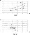
- FIG. 9-12 Specific examples of the result of the experimental results are shown in figures 9-12 .
- All figures 9-12 show experimental results of an identified process window representing acceptable laser brazing results in terms of brazing seam quality, e.g. little amount of spatter, little amount of pores formation and little or no need for refinishing work.
- the charts shown in figures 9-12 illustrate specific examples of the upper and lower limit of the acceptable process window in a process for joining two metal workpieces made of hot-dip galvanised steel by laser brazing for forming a vehicle structure, wherein the X-axis of the chart represents process speed in metres/minute and the Y-axis in the chart represents laser power in kW. No shield gas has been used in any test.
- Figure 9 shows a specific example of an identified acceptable process window for varying process speed and laser power using the following specific test parameter setting:
- Line 91 in figure 9 represents the upper limit of the acceptable process window and line 92 represents the lower limit of the acceptable process window.
- the laser power should be kept between 4 - 5.5 kW for obtaining an acceptable laser brazing result.
- Higher laser power than 5.5 kW may for example result in too much spatter and lower laser power than 4 kW may for result in pores formation.
- the specific example process window shown in figure 9 represents a very good process setting for joining two metal hot-dip galvanized workpieces by laser brazing for forming a vehicle structure.
- the process window shows that by means of the above-defined specific process acceptable laser brazing quality in accomplished over a large range of process speed 11, i.e. from 3.5 metres/minute up to 6.5 metres/minute, merely by adapting the laser power in the range from 3 - 7 kW.
- Experimental results show that that some process parameters are more relevant than others for accomplishing acceptable laser brazing quality of hid-dip galvanized steel while having a relatively high process speed.
- the following process parameters have been identified as more relevant: Beam parameter product, optical magnification level, beam spot size and material of the consumable wire.
- Experimental results show that acceptable process window is accomplished also when said relevant process parameters are varied to a certain extent. In particular, acceptable process window is accomplished when having beam parameter product lower than 10 mm ⁇ mrad, an optical magnification in the range of 1:0.5 - 1:1.5, a beam spot size in the range of 2 - 6 mm and a consumable wire comprising at least 95% copper.
- Figure 10 shows a specific example of an identified acceptable process window for varying process speed and laser power using similar specific test parameter setting as described in relation to figure 9 , but using optical magnification in the laser focus head of 1:3 instead, wherein line 91 represents the upper limit of the acceptable process window and line 92 represents the lower limit of the acceptable process window.
- the distance 82 between the first and second workpiece 1, 2 and the focusing lens arrangement 79 than must be adjusted to obtain the desired beam spot size.
- Figure 11 shows a specific example of an identified acceptable process window for varying process speed and laser power using similar specific test parameter setting as described in relation to figure 9 , but using optical magnification in the laser focus head of 1:5 instead, wherein line 91 represents the upper limit of the acceptable process window and line 92 represents the lower limit of the acceptable process window.
- the distance 82 between the first and second workpiece 1, 2 and the focusing lens arrangement 79 than must be adjusted to obtain the desired beam spot size.
- Figure 12 shows a specific example of an identified acceptable process window for varying process speed and laser power using similar specific test parameter setting as described in relation to figure 9 , wherein the optical magnification in the laser focus head was 1:1, but the consumable wire material was different, namely : ISO 24373; Cu 6560 CuSi3Mn1 (diameter 1.6 mm).
- the typical composition (weight %) of this wire is: Silicon (Si) Iron (Fe) Manganese (Mn) Zinc (Zn) Copper (CU) 2.7 - 3.2% ⁇ 0.2% 0.7 -1.3% ⁇ 0.4% Rest
Landscapes
- Engineering & Computer Science (AREA)
- Mechanical Engineering (AREA)
- Physics & Mathematics (AREA)
- Optics & Photonics (AREA)
- Plasma & Fusion (AREA)
- Chemical & Material Sciences (AREA)
- Materials Engineering (AREA)
- Robotics (AREA)
- Laser Beam Processing (AREA)
Description
- The disclosure relates to a process for joining a first metal workpiece and a second metal workpiece by laser brazing for forming a vehicle structure, see
claim 1. - The process according to the disclosure is thus particularly suitable for laser brazing of a vehicle roof panel to vehicle side panel. However, although the disclosure will be described primarily in relation to mutual joining of a roof panel and a side panel the disclosure is not restricted to this particular application, but may alternatively be used for joining other metal workpieces of a vehicle.
- The article 'Influence of different zinc coatings on laser brazing of galvanized steel', written by W. Reimann et Al. (JOURNAL OF MATERIALS PROCESSING TECHNOLOGY, IRN ISSN 0924-0136, Vol. 239, pp 75-82, 5 August 2016), describes a process of joining a first metal workpiece and a second metal workpiece by laser brazing, comprising providing the first metal workpiece and the second metal workpiece in contacting relationship so as to form an elongated contact region, wherein the first and second metal workpieces are made of hot-dip galvanized steel material, supplying a laser beam, and supplying a consumable wire of filler material to the beam spot to melt the consumable wire and braze said first and second metal workpieces together, wherein the consumable wire (9) comprises at least 95% copper.
- Laser
brazing of the joint connecting the roof panel and the side panel is nowadays common practise and this process provides a high-quality joint that requires little refinishing work before painting and enables a smooth and desirable design. - However, in the field of vehicle manufacturing by laser brazing there is continuous demand for improving the manufacturing process in terms manufacturing quality, product quality and not the least cost and time-efficiency.
- Despite the activities in the field, there is still a demand for a further improved process for joining a first metal workpiece and a second metal workpiece by laser brazing for forming a vehicle structure.
- A general object of the present disclosure is to provide an improved process for joining a first metal workpiece and a second metal workpiece by laser brazing for forming a vehicle structure.
- In particular, an object of the present disclosure is to provide a manufacturing process where the laser brazing production speed is increased with maintained high-quality joint quality.
- Still a further object of the present disclosure is to provide a manufacturing process for joining two metal workpieces by laser brazing where at least one of the first and second metal workpieces is made of hot-dip galvanized steel material. Hot-dip galvanized steel material typically has a thicker zinc coating than a conventional electro-galvanization steel material.
- These and other objects, which will become apparent in the following, are accomplished in the present invention by a process as defined in
claim 1. Details of some example embodiments and further optional features are recited in the associated dependent claims. - According to the present invention, the process for joining a first metal workpiece and a second metal workpiece by laser brazing for forming a vehicle structure comprises providing the first metal workpiece and the second metal workpiece in contacting relationship so as to form an elongated contact region, wherein at least one of the metal workpieces is made of hot-dip galvanized steel material, supplying a laser beam having a beam parameter product lower than 10 millimetre times milliradians (mm·mrad) from a laser source, guiding the laser beam through a laser focus head having a total optical magnification in the range of 1:0.5 - 1:1.5, directing the laser beam along the elongated contact region, wherein a beam spot formed where the laser beam hits the contact region has a size in the range of 2 - 6 mm (millimetres), and supplying a consumable wire of filler material to the beam spot to melt the consumable wire and braze said two metal workpieces together, wherein the consumable wire comprises at least 95% copper.
- Galvanization is the process of applying a protective zinc coating to steel metal sheet to increased corrosion resistance. There are various galvanization processes available. Conventionally, the roof panel and side panel of a vehicle have been galvanized by a process called electro-galvanization because this process is characterised by producing a relatively thin zinc coating layer on the steel metal sheets, such as for example in the range of 0.1 - 0.5 µm (micrometres), and this was desirable because it enabled laser brazing joining of the metal workpieces. An electrogalvanized coating is created by applying zinc to steel sheet by electrodeposition. This is for example performed by submerging the metal workpiece into a zinc plating bath, in which a zinc coating develops as positively charged zinc ions in the bath are electrically reduced to zinc metal and deposited on the positively charged metal workpiece.
- Another known galvanization process is hot-dip galvanizing, in which the metal workpieces after cleaning and simply submerged in a bath of molten zinc. Hot-dip galvanization is a faster process and produces a thicker zinc coating layer on the metal workpieces compared with the electro-galvanization process. The resulting zinc coating thickness may for example be in the range of 3 - 5 µm. However, until now it has not been possible to use a laser brazing process for joining hot-dip galvanized metal workpieces of a vehicle with reasonable production speed and with acceptable soldering joint quality in terms of pore formation and sputter.
- After extensive research and experimental laser brazing testing for finding process parameters that enable laser brazing joining of hot-dip galvanized metal workpieces a high product speed a set of parameter settings has now been identified as being central for achieving this objective, namely by using a laser beam having a beam parameter product lower than 10 mm·mrad, using a laser focus head having a total optical magnification in the range of 1:0.5 - 1:1.5, having a beam spot size in the range of 2 - 6 mm and a consumable wire that comprises at least 95% copper. This set-up enables laser brazing of hot-dip galvanized metal workpieces a relatively high process speed of about 3.5 - 6.5 metres per minute and with a resulting laser brazing joint that has substantially no spatter and no pores, such that the need for post-processing of the finished joint, such as grinding or polishing, is eliminated.
- The use of hot-dip galvanized metal workpieces results in improved corrosion resistance and reduced cost, and the relatively high process speed of about 3.5 - 6.5 metres per minute results in further reduced cost due to increased productivity.
- In one example embodiment, the laser beam has a beam parameter product not higher than 8 mm·mrad, and specifically in the range of 2 - 8 mm·mrad. The Beam Parameter Product (BPP) quantifies the quality of a laser beam and how well it can be focused to a small spot. A relatively low beam parameter product consequently enables use of a relatively small diameter fibre optic cable without losing too much of the laser power at the entrance of the fibre optic cable, because the focused spot should be comparable to the core size to obtain good coupling efficiency into the fibre optic cable. Moreover, since it desirable to have a total optical magnification not too far away from 1:1 in order to obtain a Gaussian laser power distribution at the beam spot and since the beam spot size should be in the range of 2 - 6 mm, a relatively small core size of the fibre optic cable is needed. For these reasons, having a beam parameter product not higher than 8 mm·mrad, and specifically in the range of 2 - 8 mm·mrad, enables the desired relatively small the beam spot size and Gaussian laser power distribution at the beam spot without losing to much laser power that the coupling between the laser source and the fibre optic cable.
- In one example embodiment, the laser focus head has a total optical magnification in the range of 1:0.7 - 1:1.3, and specifically in the range of 1:0.9 - 1:1.1. As discussed above, a total optical magnification not too far away from 1:1 results in a more or less Gaussian laser power distribution at the beam spot, and the extensive research and experimental laser brazing testing for finding appropriate process parameters has surprisingly revealed that a Gaussian laser power distribution at the beam spot improves the quality of the laser brazing joint and enables relatively high process speeds.
- Furthermore, a magnification level of about 1:1 also has the advantage of enabling also laser welding by means of the same laser equipment. In other words, this type of magnification enables dual use of the same laser equipment. This is very attractive for manufacturing companies because they can then use substantially the same laser equipment for two different manufacturing processes for increased flexibility. Moreover, the use of the same type of laser equipment for both laser brazing and laser welding results in less need for different types of replacement parts, service partners, etc.
- In an example embodiment, the beam spot has a size in the range of 3 - 5 mm. The extensive research and experimental laser brazing testing for finding appropriate process parameters has revealed that a beam spot size in the range of 3 - 5 mm results in even less spatter and pores formation while allowing a high process speed.
- In an example embodiment, the extensive research and experimental laser brazing testing for finding appropriate process parameters has surprisingly revealed that further improved laser brazing result in terms of reduced spatter and pores formation and high process speed can be obtained if the consumable wire comprises at least 96% copper, and specifically at least 96.5% copper.
- In an example embodiment, the at least one metal workpiece made of hot-dip galvanized steel material has a zinc coating in the range of 25 - 95 g/m2 (grams per square metre), specifically in the range of 35 - 75 g/m2, and more specifically in the range of 40 - 60 g/m2. Hot-dip galvanized steel has a relatively large zinc coating thickness compared with electrogalvanized coating and thereby offers an improved corrosion resistance.
- In an example embodiment, the at least one metal workpiece made of hot-dip galvanized steel material is a sheet steel with a thickness in the range of 0.3 - 1.0 mm, specifically in the range of 0.4 - 0.8 mm, and more specifically in the range of 0.5 - 0.7 mm.
- In an example embodiment, the consumable wire comprises less than 3% silicon, specifically less than 2.5% silicon, and more specifically 1 - 2.5% silicon. The extensive research and experimental laser brazing testing for finding appropriate process parameters has revealed that the consumable wire shall comprises less than 3% silicon, specifically less than 2.5% silicon, and more specifically 1 - 2.5% silicon, in order to provide the desired high quality laser brazing seam and high process speed.
- In an example embodiment, the consumable wire is of the type ISO 24373; Cu 6511 CuSi2Mn1. This particular type of consumable wire is a copper-silicon-manganese wire that has displayed very good results in terms desired high quality laser brazing seam and high process speed in combination with hot-dip galvanized sheet steel. The typical composition (weight %) of this wire is:
Silicon (Si) Tin (Sn) Manganese (Mn) Copper (CU) 1.7 - 1.9% 0.17-0,25% 0.9 - 1.1% Rest - In an example embodiment, the laser beam at the output of the laser source has a power of at least 2.5 kW, specifically at least 3.5 kW, and more specifically in the range of 3.5 - 10 kW. The extensive research and testing has showed that at laser power of at least 2.5 kW is necessary to accomplish the desired relatively high process speed. Moreover, further increased process speed is possible with increased laser power without any significant reduction on laser brazing quality.
- In an example embodiment, the laser beam at the output of the laser source has a wavelength in the range of 800-1200 nm, and specifically in the range of 900-1100 nm. This type of wavelength has proven to enable the desired high process speed and laser bracing quality.
- In an example embodiment, the process comprises guiding the laser beam from the laser source to the laser focus head through a fibre optic cable having a central core diameter of not more than 1 mm, specifically not more than 0.6 mm, and more specifically in the range of 0.2 - 0.6 mm. The central core diameter determines the minimum beam spot size at the work piece and is thus a relevant parameter for accomplishing a high quality and high speed laser brazing process.
- In an example embodiment comprising directing the laser beam along the contact region with a process speed of at least 3.5 m/min (metres per minute), specifically at least 4.5 m/min, and more specifically in the range of 3.5 - 6.5 m/min. this relatively high process speed has significant effect on the cost for manufacturing a vehicle since the elongated contact region to be joined using laser brazing between the roof panel and side panel is relatively long, and the total process time for producing the laser brazing seam at both lateral sides of the roof can therefore be significantly reduced for improved productivity.
- In an example embodiment, the process comprising supplying the consumable wire with a wire feeding rate of 50-100% of the process speed, and specifically 70-90% of the process speed. The extensive research and experimental laser brazing testing for finding appropriate process parameters has revealed that this wire feeding rate results in the desired high quality and high speed laser brazing process.
- In an example embodiment, the consumable wire has a wire diameter in the range of 0.8 - 2.4 mm, specifically in the range of 1.0 - 1.8 mm, and more specifically in the range of 1.2 - 1.6 mm. The extensive research and experimental laser brazing testing for finding appropriate process parameters has revealed that this wire feeding rate results in the desired high quality and high speed laser brazing process.
- In an example embodiment, a laser beam process direction angle between the laser beam and an outer surface of the first or second metal workpiece, in the process direction, at the beam spot, is in the range of 60-90 degrees, specifically in the range of 65-85 degrees, and more specifically in the range of 70-83 degrees. The extensive research and experimental laser brazing testing for finding appropriate process parameters has revealed that this wire feeding rate results in the desired high quality and high speed laser brazing process.
- In an example embodiment, a longitudinal axis of the filler wire adjacent the beam spot leans more forward in the process direction than a direction of the laser beam at the beam spot, and wherein a feed angle between the laser beam and the longitudinal axis of the consumable wire, in the process direction, adjacent the beam spot, is in the range of 10-50 degrees, and specifically in the range of 20-40 degrees. The extensive research and experimental laser brazing testing for finding appropriate process parameters has revealed that this wire feeding rate results in the desired high quality and high speed laser brazing process.
- In an example embodiment, one of the first and second metal workpieces is a vehicle roof panel and that the other metal workpiece is a vehicle side panel.
- Further features of, and advantages with, the present disclosure will become apparent when studying the appended claims and the following description.
- The various example embodiments of the disclosure, including its particular features and example advantages, will be readily understood from the following illustrative and non-limiting detailed description and the accompanying drawings, in which:
-
Fig. 1 shows a perspective view of a first example embodiment of a process for joining a first metal workpiece and a second metal workpiece by laser brazing; -
Fig. 2 shows the basic process steps of the laser brazing process according to the disclosure; -
Fig. 3 shows a 3D view of an example embodiment of a specific application of the laser brazing process according to the disclosure; -
Fig. 4 shows a section along cut A-A infigure 3 ; -
Fig. 5 shows a similar view asfigure 4 including a schematic laser beam; -
Fig. 6 shows a schematic 2D view of the laser brazing process according to the disclosure; -
Fig. 7 shows schematic component parts of the laser beam supply equipment; -
Fig. 8 shows an example view of Gaussian-type laser beam intensity; -
Fig. 9-12 show specific examples of acceptable process windows derived from the experimental results. - The present disclosure will now be described more fully hereinafter with reference to the accompanying drawings, in which exemplary embodiments of the disclosure are shown. The disclosure may, however, be embodied in many different forms and should not be construed as limited to the embodiments set forth herein; rather, these embodiments are provided for thoroughness and completeness. Like reference characters refer to like elements throughout the description. The drawings are not necessarily to scale and certain features may be exaggerated in order to better illustrate and explain the exemplary embodiments of the present disclosure.
-
Figure 1 schematically depicts a process for joining afirst metal workpiece 1 and asecond metal workpiece 2 by laser brazing for forming a vehicle structure. The first andsecond metal workpieces elongated contact region 3. Moreover, at least one of themetal workpieces laser source 4 supplies a laser beam to alaser focus head 5 via afibre optic cable 6, and a focusedsingle laser beam 7 is directed to thecontact region 3. Thelaser focus head 5 is of a monofocus type, i.e. it supplies a single laser beam. Asingle beam spot 8 is consequently formed where the laser beam hits the contact region and aconsumable wire 9 of filler material is simultaneously supplied to the beam spot alongfeed direction 10. The heat of thelaser beam 7 melts theconsumable wire 9 when supplied to the beam spot and the melted filler material penetrates into the gap in the joint between the first andsecond metal workpieces - This is a continuous process that progresses with a certain process speed in a
process direction 11 along theelongated contact region 3, from a desiredstart point 13 to a desiredend point 14, and newconsumable wire 9 is continuously fed to thebeam spot 8 where the consumable wire is melted by thelaser beam 7. Typically, both thelaser focus head 5, thesupply roll 12 of consumable wire and a guiding device (not showed) for guiding and feeding theconsumable wire 9 to thebeam spot 8 is continuously moved with a process speed in theprocess direction 11 along theelongated contact region 3, and the first andsecond metal workpieces - As soon as the
laser beam spot 8 has moved past an area of melted filler material the melted filler material directly starts to cool down and subsequently solidify to form a smooth joint with high joint surface quality, high joint corrosion resistance and low or no need for refinishing work. - The schematic process for joining the first and
second metal workpieces figure 1 is described more in detail with reference tofigure 2 , which discloses the basic process steps for the joining process. - The process comprises a first step S1 of providing the
first metal workpiece 1 and thesecond metal workpiece 2 in contacting relationship so as to form anelongated contact region 3, wherein one of both of themetal workpieces - Hot-dip galvanized steel material is a steel material that has been galvanized in a hot-dip galvanizing process. This is typically performed by first cleaning the steel material, such as sheet steel, and subsequently submerging the steep material in a bath of molten zinc. Hot-dip galvanization is a relatively fast process that produces a relatively thick zinc coating layer on the steel material, such as for example in the range of 3 - 5 µm.
- Another option for characterising the resulting zinc layer coating accomplished by hot-dip galvanization is to review the coating thickness in terms of weight per square metre. For example, a metal workpiece made of hot-dip galvanized steel material typically has a zinc coating in the range of 25 - 95 g/m2, specifically in the range of 35 - 75 g/m2, and more specifically in the range of 40 - 60 g/m2.
- A second step S2 of the process for joining the first and
second metal workpieces laser source 4. - Specifically, the laser beam may have a beam parameter product (BPP) not higher than 8 mm·mrad, and more specifically in the range of 2 - 8 mm·mrad.
- The beam parameter product (BPP) of a laser beam is defined as the product of beam radius (measured at the beam waist) and the beam divergence half-angle (measured in the far field). The usual units are mm x mrad (millimetres multiplied with milliradians). The BPP is often used to specify the beam quality of a laser beam: the higher the beam parameter product, the lower is the beam quality.
- The laser beam supplied at the output of the
laser source 4 may for example have a power of at least 2.5 kW, specifically at least 3.5 kW, and more specifically in the range of 3.5 - 10 kW. Generally, increased power level of the laser beam enables higher production speed. - The laser beam at the output of the
laser source 4 may for example have a wavelength in the range of 800-1200 nm, and specifically in the range of 900-1100 nm. - A third step S3 of the process for joining the first and second metal workpieces by laser brazing comprises guiding the laser beam through the
laser focus head 5, which has a total optical magnification in the range of 1:0.5 - 1:1.5. The laser focus head may alternatively have a total optical magnification in the range of 1:0.7 - 1:1.3, and specifically in the range of 1:0.9 - 1:1.1. The total optical magnification of alaser focus head 5 is determined by the ratio between the total focal length of the laser head's collimating lens arrangement and focus lens arrangement, as will be described more in detail below with reference tofigure 7 . - A fourth step S4 of the process for joining the first and
second metal workpieces laser beam 7 along theelongated contact region 3. Abeam spot 8 is formed where thelaser beam 7 hits the contact region has a size in the range of 2 - 6 mm. Thebeam spot 8 is generally circular and it is the diameter that defines the size of thebeam spot 8. In certain applications, abeam spot 8 has a size in the range of 3 - 5 mm may be selected. Thelaser beam 7 is directed along thecontact region 3 with aprocess speed 11 of at least 3.5 m/min, specifically at least 4.5 m/min, and more specifically in the range of 3.5 - 6.5 m/min. This process speed results in a relatively high productivity of the laser brazing equipment. - A fifth step S5 of the process for joining the first and
second metal workpieces consumable wire 9 of filler material to thebeam spot 8 to melt the consumable wire and braze said twometal workpieces - Furthermore, the consumable wire comprises less than 3% silicon, specifically less than 2.5% silicon, and more specifically 1 - 2.5% silicon. The consumable wire may for example be of the type: ISO 24373; Cu 6511 CuSi2Mn1.
- The consumable wire has typically a wire diameter in the range of 0.8 - 2.4 mm, specifically in the range of 1.0 - 1.8 mm, and more specifically in the range of 1.2 - 1.6 mm. Moreover, the consumable wire is generally supplied with a wire feeding rate of 50-100% of the process speed, and specifically 70-90% of the process speed.
- Turning now to
figure 3 , an example of a specific application for applying the disclosed laser brazing process is illustrated.Figure 3 shows schematically an example of avehicle structure 30 with afront part 38, arear part 39, avehicle length direction 97, a vehiclelateral direction 98 and a vehiclevertical direction 99. Thevehicle structure 30 is illustrated in a manufacturing state in which the sheet metal components of the structure have been joined together to a form a rigid structure of the finished vehicle. Details such as doors, hoods, the drive train, vehicle interior, etc. have not yet been assembled to the vehicle structure. - In
figure 3 , holes 31 for the front and rear door can be seen, as well as thehole 32 for the front wind screen andrear wheel compartment 33.Figure 3 further shows a roof panel 34 avehicle side panel 35, as well as joint 36 there between. - The disclosed laser brazing process may for example be applied for mutually joining the
roof panel 34 and theside panel 35 by means of laser brazing. Thefirst metal workpiece 1 may thus be theroof panel 34 and thesecond metal workpiece 2 may thevehicle side panel 35. - One or both of the
roof panel 34 andside panel 35 may thus be made of hot-dip galvanized sheet steel material. The sheet steel material may for example have a thickness in the range of 0.3 - 1.0 mm, specifically in the range of 0.4 - 0.8 mm, and more specifically in the range of 0.5 - 0.7 mm. -
Figure 4 schematically illustrates an example of a cross-section of theroof panel 34,side panel 35, and laser brazing joint 36 along section A-A shown infigure 3 . The underlying body reinforcing structure of the vehicle is not showed infigure 4 . - The geometry and configuration of the
roof panel 34 andside panel 35 in the region of the joint 36 can vary but some kind of flange joint may be preferred. In a flange joint a downwardly foldedflange 41 of theroof panel 34 abuts and contacts a downwardly foldedflange 42 of theside panel 36. This design provides a small cavity between theroof panel 34 andside panel 35 at the joint 36, which cavity may be filled with a laser brazing seam formed of molten filler material of theconsumable wire 9. - The roof panel fold 43 between the substantially flat portion of the roof panel facing upwards and the downwardly facing
flange 41 of theroof panel 34 may have a radius of not more than 3 mm, specifically not more than 2 mm, and more specifically in the range of 1-2 mm. This parameter is relevant from a laser brazing process perspective because it influences the amount of molten filler material that is required to fill the joint 36. A radius of more than 3 mm may result in too large fill level, such that the finished laser brazing joint is not sufficiently flush with theouter surface 44 of theroof panel 34. On the other hand, a radius of the roof panel fold 43 of less than 1 mm may result in a too small cavity, such that the strength of the laser brazing joint is low. -
Parameter 45 denotes the angle of the downwardly foldedflange 42 of theside panel 35 with respect to avertical direction 99 andparameter 46 denotes the angle between the downwardly foldedflange 42 of theside panel 35 and the downwardly foldedflange 41 of theroof panel 34.Parameter 45 may for example be set to about 30 - 60 degrees, specifically to about 40 - 50 degrees, and more specifically about 45 degrees, because these ranges of said angle enables an high level of tolerance in the lateral distance between side panels on the left and right side of the vehicle, since theroof panel 34 may then automatically fit betweenside panels 35 on the left and right side of the vehicle at a certain height of the roof. - In other words, even if the distance between the
side panels 35 on the left and right sides of the vehicle varies somewhat between individual vehicles theroof panel 34 will always fit and will be automatically slightly adjusted in height. - However, a too
small angle 45 results in that small variation in lateral distance between the left andright side panels 35 will results in relatively large undesirable vertical position displacement of theroof panel 34. Moreover, a toolarge angle 45 may result in that thecontact point 47 between the roof andside panels flanges angle 45. - Furthermore,
angle 46 should preferably be positive, specifically in the range of 1-10 degrees, because with anegative angle 46 thecontact point 47 between the roof andside panels flanges -
Parameter 48 may be set to about 2-5 mm because this setting may reduce the risk for complete disintegration of the roof panel to side panel joint in case of a vehicle crash. -
Parameter 49 may be set to at least 1 mm, specifically in the range of 1 - 4 mm, such that the inwardly foldedflange 42 of theside panel 35 provides sufficient support to theroof panel 34 in view of the tolerances of the distance between the left andright side panels 35 of the vehicle. - The
parameter 50 may be set to at least 3 mm, specifically in the range of 3 - 10 mm, such that the inwardly foldedflange 41 of theroof panel 34 provides sufficient contact surface for supporting theroof panel 34 in view of the tolerances of the distance between the left andright side panels 35 of the vehicle. - The
parameter 51 may be set to at least 1 mm, specifically in the range of 1-10 mm, for proving desired reinforcement of the roof panel against bending, etc. - The
parameter 52 may be set to at least 1 mm, specifically in the range of 1-10, for avoiding undesired contact between theflanges -
Figure 5 schematically illustrates the cross-section of theroof panel 34,side panel 35, and laser brazing joint 36 along section A-A shown infigure 3 , and here also with thelaser beam 7 included. Thelaser beam 7 may for example have adirection 62 that is parallel with thevertical direction 99, as seen in thelength direction 97 of the vehicle. In other words, thelaser beam 7 has zero angle in thelateral direction 98 and does not lean towards theside panel 35 or towards therood panel 34. - Although the laser brazing process has been described primarily for joining the roof panel and side panel of the vehicle, the laser brazing process according to the disclosure may alternatively be used for joining other metal workpieces of a vehicle, such as for example metal parts forming the rear trunk lid.
-
Figure 6 schematically illustrates a 2-D view of the laser brazing process according to the disclosure. Infigure 6 thelaser focus head 5 and consumablewire supply roll 12 is moved in aprocess direction 11 with a certain process speed, whereby the first andsecond workpieces direction 62 of thelaser beam 7 and anouter surface 63 of the first orsecond metal workpiece process direction 11, at thebeam spot 8, is in the range of 60-90 degrees, specifically in the range of 65-85 degrees, and more specifically in the range of 70-83 degrees. This essentially means that thelaser focus head 5 has a forward inclination, i.e. aprocess direction 11 inclination, or that thedirection 62 of thelaser beam 7 is perpendicular to the surface of theworkpieces - A
longitudinal axis 64 of theconsumable wire 9 adjacent thebeam spot 8 leans more forward, in a plane of theprocess direction 11, than thedirection 62 of thelaser beam 7. In particular, afeed angle 65 between thedirection 62 of thelaser beam 7 and thelongitudinal axis 64 of theconsumable wire 9, in the plane of theprocess direction 11, adjacent thebeam spot 8, may be set in the range of 10-50 degrees, and specifically in the range of 20-40 degrees. The specific ranges have in experimental testing shown to provide excellent laser brazing finish also with high process speed. -
Figure 7 schematically illustrates an example embodiment of an optical arrangement of thelaser source 4 andlaser focus head 5. Thelaser source 4 may have one ormore laser emitters 70 that generate alaser beam 7 that is guided through a condensinglens 72 before being guided into the entrance of thefibre optic cable 6. - A beam parameter product not higher than 8 mm·mrad, and specifically in the range of 2 - 8 mm·mrad, ensures a relatively
narrow waist 73 of thelaser beam 7, such that the loss of power of the laser beam upon entrance into the fibre optic cable is kept small, considering that the focused spot of the laser beam at thewaist 73 should be comparable to the core size of the fibre optic cable to obtain good coupling efficiency of the laser beam into the fibre optic cable. - The
fibre optic cable 6 is used for guiding the laser beam from thelaser source 4 to thelaser focus head 5. This allows significant relative motion between thelaser source 4 andlaser focus head 5 for improved flexibility. Acentral core 74 of thefibre optic cable 6 may have adiameter 75 of not more than 1 mm, specifically not more than 0.6 mm, and more specifically in the range of 0.2 - 0.6 mm. - The diameter of the
waist 76 of thelaser beam 7 exiting the laser focus head is typically substantially identical to the core diameter of thefibre optic cable 6 if optical magnification of 1:1 is applied in thelaser focus head 5. This may be derived from the following equation:
diameter 75 of thecentral core 74 of thefibre optic cable 6 in the range of 0.2 - 0.6 mm. - An optical magnification in the range of 1:0.5 - 1:1.5, specifically in the range of 1:0.7 - 1:1.3, and more specifically in the range of 1:0.9 - 1:1.1 is deemed advantageous because this does not significantly distort the Gaussian intensity form of the
laser beam 7 supplied from thelaser source 4. Experimental results show that a Gaussian intensity curve has advantageous effect on the quality of the laser brazing process. -
Figure 8 schematically illustrates the intensity profile of Gaussian laser beam, where the X-axis represent location within the laser beam and the Y-axis represents laser beam intensity. As shown, theintensity 85 is largest at thecentre 0 of the beam and the intensity smoothly decays from its maximum at the centre to zero intensity at the circumferential edges of thebeam 7. The total thickness of the beam in this example is about 600 µm. - The
focus head 5 has acollimating lens arrangement 77 with a firstfocal length 78 corresponding to the distance between the exit point, i.e. focal point, of thelaser beam 7 exiting thefibre optic cable 6 and thecollimating lens arrangement 77. Thefocus head 5 further has afocus lens arrangement 79 with a secondfocal length 80 defined by the distance between thefocus lens arrangement 79 and thewaist 76, i.e. focal point of the of thelaser beam 7 exiting thelaser focus head 7. - It is the ratio between the first
focal length 78 and the secondfocal length 80 that determines the optical magnification of thelaser focus head 5. In the illustrated schematic example of the laser focus head both thecollimating lens arrangement 77 and thefocus lens arrangement 79 are illustrated showing a single lens each. However, each of thecollimating lens arrangement 77 and thefocus lens arrangement 79 may alternative consists of a plurality of lenses, which combined provides a certain focal length. - The laser beam exiting the
fibre optic cable 6 is guided through thecollimating lens arrangement 77 and subsequently through thefocus lens arrangement 79 to form thelaser beam 7 exiting thelaser focus head 5. Thelaser beam 7 exiting thelaser focus head 5 is directed towards the elongated contact region of the first andsecond workpieces 1, 22, and abeam spot 8 formed where the laser beam hits the contact region has abeam spot size 81 in the range of 2 - 6 mm, specifically in the range of 3-5 mm. - Since the
waist dimension 76 of thelaser beam 7, which for example may be about 0.2 - 0.6 mm with an optical magnification near 1:1, may be much smaller than the desired beam spot size of 3-5 mm, the first andsecond workpiece smaller distance 82 from the focusing lendarrangement 79 than the secondfocal length 80. - The specific process parameters underlying the laser brazing process according to the disclosure have been identified by conducting extensive research and experimental laser brazing testing, wherein the aim specifically was to identify process parameters that would enables laser brazing of hot-dip galvanised steel with high process speed and high brazing joint finish.
- Specific examples of the result of the experimental results are shown in
figures 9-12 . Allfigures 9-12 show experimental results of an identified process window representing acceptable laser brazing results in terms of brazing seam quality, e.g. little amount of spatter, little amount of pores formation and little or no need for refinishing work. The charts shown infigures 9-12 illustrate specific examples of the upper and lower limit of the acceptable process window in a process for joining two metal workpieces made of hot-dip galvanised steel by laser brazing for forming a vehicle structure, wherein the X-axis of the chart represents process speed in metres/minute and the Y-axis in the chart represents laser power in kW. No shield gas has been used in any test. -
Figure 9 shows a specific example of an identified acceptable process window for varying process speed and laser power using the following specific test parameter setting: - Consumable wire: ISO 24373; Cu 6511 CuSi2Mn1 (diameter 1.6 mm)
- Consumable wire feed speed: about 80% of process speed
- Optical magnification in the laser focus head: 1:1,
- Single spot laser beam with 4 mm spot size,
- Fibre optic cable with 0.2 mm core diameter,
- Laser beam lateral angle: 0 degree
- Laser beam process direction angle: 15 degrees
- Beam parameter product: 2 mm·mrad
- Roof panel fold radius: 2 mm
-
Line 91 infigure 9 represents the upper limit of the acceptable process window andline 92 represents the lower limit of the acceptable process window. Hence, targeting for example a process speed of 5.5 metres/minute the laser power should be kept between 4 - 5.5 kW for obtaining an acceptable laser brazing result. Higher laser power than 5.5 kW may for example result in too much spatter and lower laser power than 4 kW may for result in pores formation. - The specific example process window shown in
figure 9 represents a very good process setting for joining two metal hot-dip galvanized workpieces by laser brazing for forming a vehicle structure. The process window shows that by means of the above-defined specific process acceptable laser brazing quality in accomplished over a large range ofprocess speed 11, i.e. from 3.5 metres/minute up to 6.5 metres/minute, merely by adapting the laser power in the range from 3 - 7 kW. - Experimental results show that that some process parameters are more relevant than others for accomplishing acceptable laser brazing quality of hid-dip galvanized steel while having a relatively high process speed. The following process parameters have been identified as more relevant: Beam parameter product, optical magnification level, beam spot size and material of the consumable wire. Experimental results show that acceptable process window is accomplished also when said relevant process parameters are varied to a certain extent. In particular, acceptable process window is accomplished when having beam parameter product lower than 10 mm·mrad, an optical magnification in the range of 1:0.5 - 1:1.5, a beam spot size in the range of 2 - 6 mm and a consumable wire comprising at least 95% copper.
-
Figure 10 shows a specific example of an identified acceptable process window for varying process speed and laser power using similar specific test parameter setting as described in relation tofigure 9 , but using optical magnification in the laser focus head of 1:3 instead, whereinline 91 represents the upper limit of the acceptable process window andline 92 represents the lower limit of the acceptable process window. An optical magnification of 1:3 means that thelaser beam 7 leaving thelaser focus head 5 has a diameter of thewaist 76 substantially equal to three times thecore diameter 75 of thefibre optic cable 6, i.e. about 3 x 0.6 mm = 1.8 mm in the specific experimental test setting. Thedistance 82 between the first andsecond workpiece lens arrangement 79 than must be adjusted to obtain the desired beam spot size. - The specific example process window showed in
figure 10 shows that optical magnification of 1:3 results in a very narrow acceptable process window that does not allow higher process speed than 4.5 metres/min. -
Figure 11 shows a specific example of an identified acceptable process window for varying process speed and laser power using similar specific test parameter setting as described in relation tofigure 9 , but using optical magnification in the laser focus head of 1:5 instead, whereinline 91 represents the upper limit of the acceptable process window andline 92 represents the lower limit of the acceptable process window. An optical magnification of 1:5 means that thelaser beam 7 leaving thelaser focus head 5 has a diameter of thewaist 76 substantially equal to five times thecore diameter 75 of thefibre optic cable 6, i.e. about 5 x 0.6 mm = 3.0 mm in the specific experimental test setting. Thedistance 82 between the first andsecond workpiece lens arrangement 79 than must be adjusted to obtain the desired beam spot size. - The specific example process window showed in
figure 11 shows that optical magnification of 1:5 results in a relatively narrow acceptable process window that does not allow higher process speed than 5.5 metres/min. -
Figure 12 shows a specific example of an identified acceptable process window for varying process speed and laser power using similar specific test parameter setting as described in relation tofigure 9 , wherein the optical magnification in the laser focus head was 1:1, but the consumable wire material was different, namely : ISO 24373; Cu 6560 CuSi3Mn1 (diameter 1.6 mm). The typical composition (weight %) of this wire is:Silicon (Si) Iron (Fe) Manganese (Mn) Zinc (Zn) Copper (CU) 2.7 - 3.2% ≤ 0.2% 0.7 -1.3% ≤ 0.4% Rest - The specific example process window showed in
figure 12 shows that consumable CuSi3Mn1 results in a very restrictive acceptable process window with a maximal process speed of only 3.5 metres/min.Line 91 represents the upper limit of the acceptable process window andline 92 represents the lower limit of the acceptable process window. - The above description of the example embodiments of the present disclosure and the accompanying drawings are to be regarded as a non-limiting example of the disclosure and the scope of protection is defined by the appended claims. Any reference sign in the claims should not be construed as limiting the scope.
Claims (14)
- A process for joining a first metal workpiece (1) and a second metal workpiece (2) by laser brazing for forming a vehicle structure, comprising the following steps :providing the first metal workpiece (1) and the second metal workpiece (2) in contacting relationship so as to form an elongated contact region (3), wherein at least one of the first and second metal workpieces (1, 2) is made of hot-dip galvanized steel material,supplying a laser beam (7) having a beam parameter product lower than 10 mm·mrad from a laser source (4),guiding the laser beam (7) through a laser focus head (5) having a total optical magnification in the range of 1:0.5 - 1:1.5,directing the laser beam (7) along the elongated contact region (3), wherein a beam spot (8) formed where the laser beam (7) hits the contact region (3) has a size in the range of 2 - 6 mm, andsupplying a consumable wire (9) of filler material to the beam spot (8) to melt the consumable wire (9) and braze said first and second metal workpieces (1, 2) together, wherein the consumable wire (9) comprises at least 95% copper.
- The process according to claim 1, wherein the laser beam (7) has a beam parameter product not higher than 8 mm·mrad, and specifically in the range of 2 - 8 mm·mrad, and/or wherein the laser focus head (5) has a total optical magnification in the range of 1:0.7 - 1:1.3, and specifically in the range of 1:0.9 - 1:1.1, and/or wherein the beam spot (8) has a size in the range of 3 - 5 mm, and/or wherein the consumable wire (9) comprises at least 96% copper, and specifically at least 96.5% copper.
- The process according to any of the preceding claims, wherein the at least one of the first and second metal workpieces (1, 2) made of hot-dip galvanized steel material has a zinc coating in the range of 25 - 95 g/m2, specifically in the range of 35 - 75 g/m2, and more specifically in the range of 40 - 60 g/m2.
- The process according to any of the preceding claims, wherein the at least one of the first and second metal workpieces (1, 2) made of hot-dip galvanized steel material is made of sheet steel with a thickness in the range of 0.3 - 1.0 mm, specifically in the range of 0.4 - 0.8 mm, and more specifically in the range of 0.5 - 0.7 mm.
- The process according to any of the preceding claims, wherein the consumable wire (9) comprises less than 3% silicon, specifically less than 2.5% silicon, and more specifically 1 - 2.5% silicon.
- The process according to any of the preceding claims, wherein the consumable wire (9) is of the type ISO 24373; Cu 6511 CuSi2Mn1.
- The process according to any of the preceding claims, wherein the laser beam (7) at the output of the laser source (4) has a power of at least 2.5 kW, specifically at least 3.5 kW, and more specifically in the range of 3.5 - 10 kW.
- The process according to any of the preceding claims, comprising guiding the laser beam (7) from the laser source (4) to the laser focus head (5) through a fibre optic cable (6) having a central core diameter (75) of not more than 1 mm, specifically not more than 0.6 mm, and more specifically in the range of 0.2 - 0.6 mm.
- The process according to any of the preceding claims, comprising directing the laser beam (7) along the contact region (3) with a process speed of at least 3.5 m/min, specifically at least 4.5 m/min, and more specifically in the range of 3.5 - 6.5 m/min.
- The process according to any of the preceding claims, comprising supplying the consumable wire (9) with a wire feeding rate of 50-100% of the process speed, and specifically 70-90% of the process speed.
- The process according to any of the preceding claims, wherein the consumable wire (9) has a wire diameter in the range of 0.8 - 2.4 mm, specifically in the range of 1.0 -1.8 mm, and more specifically in the range of 1.2 - 1.6 mm.
- The process according to any of the preceding claims, wherein a laser beam process direction angle (61) between the laser beam (7) and an outer surface (63) of the first or second metal workpiece (1, 2), in a plane of the process direction (11), at the beam spot (8), is in the range of 60-90 degrees, specifically in the range of 65-85 degrees, and more specifically in the range of 70-83 degrees.
- The process according to any of the preceding claims,wherein a longitudinal axis (64) of the consumable wire (9) adjacent the beam spot (8) has a larger forward inclination, in a plane of the process direction (11), than a direction (62) of the laser beam (7) at the beam spot (8), andwherein a feed angle (65) between the direction (62) of the laser beam (7) and the longitudinal axis (64) of the consumable wire (9), in the plane of the process direction (11), adjacent the beam spot (8), is in the range of 10-50 degrees, and specifically in the range of 20-40 degrees.
- The process according to any of the preceding claims, wherein one of the first and second metal workpieces (1, 2) is a vehicle roof panel (34) and that the other metal workpiece is a vehicle side panel (35).
Priority Applications (4)
| Application Number | Priority Date | Filing Date | Title |
|---|---|---|---|
| EP18155157.3A EP3520945B1 (en) | 2018-02-05 | 2018-02-05 | Laser brazing process |
| CN201980010249.1A CN111655415B (en) | 2018-02-05 | 2019-01-15 | Laser brazing process |
| PCT/CN2019/071816 WO2019149064A1 (en) | 2018-02-05 | 2019-01-15 | Laser brazing process |
| US16/937,173 US11986898B2 (en) | 2018-02-05 | 2020-07-23 | Laser brazing process |
Applications Claiming Priority (1)
| Application Number | Priority Date | Filing Date | Title |
|---|---|---|---|
| EP18155157.3A EP3520945B1 (en) | 2018-02-05 | 2018-02-05 | Laser brazing process |
Publications (2)
| Publication Number | Publication Date |
|---|---|
| EP3520945A1 EP3520945A1 (en) | 2019-08-07 |
| EP3520945B1 true EP3520945B1 (en) | 2021-01-13 |
Family
ID=61163596
Family Applications (1)
| Application Number | Title | Priority Date | Filing Date |
|---|---|---|---|
| EP18155157.3A Active EP3520945B1 (en) | 2018-02-05 | 2018-02-05 | Laser brazing process |
Country Status (4)
| Country | Link |
|---|---|
| US (1) | US11986898B2 (en) |
| EP (1) | EP3520945B1 (en) |
| CN (1) | CN111655415B (en) |
| WO (1) | WO2019149064A1 (en) |
Families Citing this family (4)
| Publication number | Priority date | Publication date | Assignee | Title |
|---|---|---|---|---|
| US20210046568A1 (en) * | 2019-08-13 | 2021-02-18 | Honda Motor Co., Ltd. | Bonding structure of dissimilar metal members and precursor thereof |
| DE102019217912A1 (en) * | 2019-11-20 | 2021-05-20 | Volkswagen Aktiengesellschaft | Process for laser beam soldering |
| CN113351954B (en) * | 2021-07-06 | 2023-05-26 | 河北华通重工机械制造有限公司 | Sealing steel ring surface welding seam brazing filling device |
| CN113579388B (en) * | 2021-08-24 | 2023-04-28 | 上汽通用汽车有限公司 | Roof laser brazing thermal deformation simulation method and roof laser brazing method |
Family Cites Families (27)
| Publication number | Priority date | Publication date | Assignee | Title |
|---|---|---|---|---|
| JPH0433791A (en) * | 1990-05-29 | 1992-02-05 | Matsushita Electric Ind Co Ltd | Laser beam machine |
| JP3537019B2 (en) * | 1996-11-22 | 2004-06-14 | 日産自動車株式会社 | Car body panel brazing method |
| DE19750586B4 (en) * | 1997-11-17 | 2007-05-16 | Volkswagen Ag | Laser soldering |
| JP3901964B2 (en) * | 2001-08-15 | 2007-04-04 | 日鐵溶接工業株式会社 | Laser welding method of contact part with galvanized layer |
| JP2003334657A (en) * | 2002-05-20 | 2003-11-25 | Daihen Corp | Arc spot welding method for galvanized sheet iron lap joint |
| US6906281B2 (en) * | 2003-03-03 | 2005-06-14 | Dana Corporation | Method for laser welding of metal |
| JP4470482B2 (en) * | 2003-12-22 | 2010-06-02 | Jfeスチール株式会社 | Brazing method for lap fillet joints |
| JP4331012B2 (en) * | 2004-02-12 | 2009-09-16 | 本田技研工業株式会社 | Hard solder and brazing method using this hard solder |
| CN1988981A (en) * | 2004-06-04 | 2007-06-27 | 焊接技术有限公司 | Method for connecting joining parts by hard-soldering or welding, and system for carrying out said method |
| JP4506575B2 (en) * | 2005-06-17 | 2010-07-21 | トヨタ自動車株式会社 | Galvanized steel sheet laser brazing device, galvanized steel sheet laser brazing method, brazed galvanized steel sheet manufacturing method. |
| JP2007075872A (en) * | 2005-09-16 | 2007-03-29 | Nissan Motor Co Ltd | Laser brazing welding process |
| KR100711453B1 (en) * | 2005-12-26 | 2007-04-24 | 주식회사 포스코 | Welding method of high carbon steel for endless hot rolling |
| FR2897007B1 (en) * | 2006-02-03 | 2008-04-11 | Air Liquide | METHOD OF CUTTING WITH A FIBER LASER WITH BEAM PARAMETER CONTROL |
| FR2898529B1 (en) * | 2006-03-15 | 2008-04-25 | Air Liquide | SOUDO-BRAZING OF STEEL PARTS WITH COPPER WIRE AND OXIDIZING GAS MIXTURE |
| EP1920864B1 (en) * | 2006-11-13 | 2022-07-13 | Volvo Car Corporation | Method for laser brazing with twinspot |
| JP2008207246A (en) * | 2007-01-31 | 2008-09-11 | Jfe Steel Kk | Laser brazing method |
| JP5494158B2 (en) * | 2010-04-12 | 2014-05-14 | 新日鐵住金株式会社 | Laser arc brazing method |
| DK2548714T3 (en) * | 2011-07-21 | 2013-11-11 | Ems Patent Ag | Laser beam welding method and thus formed mold parts |
| DE102012204927B3 (en) * | 2012-03-27 | 2013-07-04 | Thomas Ammersbach | A job-welded workpiece and method of making a job-welded workpiece |
| CN102935560B (en) * | 2012-11-14 | 2015-01-14 | 四川大西洋焊接材料股份有限公司 | Silicon bronze solder wire and preparation method thereof |
| JP5983345B2 (en) * | 2012-11-20 | 2016-08-31 | トヨタ自動車株式会社 | Laser brazing method for vehicle roof |
| JP5929948B2 (en) * | 2014-02-28 | 2016-06-08 | トヨタ自動車株式会社 | Weld inspection method |
| MY186734A (en) * | 2014-10-03 | 2021-08-15 | Honda Motor Co Ltd | Vehicle roof structure and method for manufacturing vehicle roof structure |
| JP5955370B2 (en) * | 2014-10-29 | 2016-07-20 | 株式会社神戸製鋼所 | Method for producing metal joined body |
| CN109475975B (en) * | 2016-08-04 | 2021-08-17 | 通快激光英国有限公司 | Device and method for laser processing material |
| JP6774303B2 (en) * | 2016-11-02 | 2020-10-21 | 株式会社Subaru | Laser brazing device and method of cutting brazing wire using laser brazing device |
| US20190061053A1 (en) * | 2017-08-24 | 2019-02-28 | GM Global Technology Operations LLC | Laser brazing of metal workpieces with relative movement between laser beam and filler wire |
-
2018
- 2018-02-05 EP EP18155157.3A patent/EP3520945B1/en active Active
-
2019
- 2019-01-15 CN CN201980010249.1A patent/CN111655415B/en active Active
- 2019-01-15 WO PCT/CN2019/071816 patent/WO2019149064A1/en active Application Filing
-
2020
- 2020-07-23 US US16/937,173 patent/US11986898B2/en active Active
Non-Patent Citations (1)
| Title |
|---|
| REIMANN WILFRIED ET AL: "Influence of different zinc coatings on laser brazing of galvanized steel", JOURNAL OF MATERIALS PROCESSING TECHNOLOGY, ELSEVIER, NL, vol. 239, 5 August 2016 (2016-08-05), pages 75 - 82, XP029738787, ISSN: 0924-0136, DOI: 10.1016/J.JMATPROTEC.2016.08.004 * |
Also Published As
| Publication number | Publication date |
|---|---|
| CN111655415B (en) | 2022-07-15 |
| US11986898B2 (en) | 2024-05-21 |
| WO2019149064A1 (en) | 2019-08-08 |
| CN111655415A (en) | 2020-09-11 |
| EP3520945A1 (en) | 2019-08-07 |
| US20200353550A1 (en) | 2020-11-12 |
Similar Documents
| Publication | Publication Date | Title |
|---|---|---|
| US11986898B2 (en) | Laser brazing process | |
| US20190061053A1 (en) | Laser brazing of metal workpieces with relative movement between laser beam and filler wire | |
| EP3459675B1 (en) | Laser cutting and machining method for plated steel plate, laser cut-and-machined product, laser machining head | |
| US10052720B2 (en) | Method of laser welding coated steel sheets with addition of alloying elements | |
| JP5110642B2 (en) | Manufacturing method of welded section steel | |
| US10052721B2 (en) | Method of laser welding coated steel sheets with addition of alloying elements | |
| DE102015117454A1 (en) | LASER HEAT WELDING WELDING OF ALUMINUM ALLOYS WITH DOUBLE CROSS-LASER RADIATION | |
| JP7081055B2 (en) | Method for fusion welding of thin steel sheets of one or more press-hardened steels | |
| US20200189035A1 (en) | Method and Device for Fusion Welding One or a Plurality of Steel Sheets Made of Press-Hardenable Steel | |
| CN113399835A (en) | Laser-electric arc hybrid welding method suitable for narrow gap welding of thick-wall component | |
| WO2019171150A1 (en) | Method for producing a welded metal blank and thus obtained welded metal blank | |
| WO2016047008A1 (en) | Method for laser welding of materials with different thicknesses and welded member having different thicknesses produced by said method | |
| US10478919B2 (en) | Method for producing aluminum joined body | |
| CN114603255A (en) | Laser welding of coated steel blanks with filler wire | |
| JP2010201434A (en) | Laser brazing method | |
| DE102016014970B4 (en) | Process for laser beam soldering of at least two hot-dip coated components or metal sheets | |
| EP4247582A1 (en) | Method for joining steel parts | |
| Kimura et al. | Laser brazing phenomena of galvanized steel and pit formation mechanism | |
| EP4282571A1 (en) | Laser brazing joining method | |
| 崔凌越 et al. | Microstructure and mechanical properties of laser welding-brazed aluminum alloy to steel with CuSi3 filler metal | |
| JP7160090B2 (en) | Composite welding method for metallic materials and butt welding member for metallic materials | |
| WO2022185989A1 (en) | Laser brazing joining method | |
| DE102018105896A1 (en) | Welding device and a method for use in the welding device | |
| CN118679024A (en) | Laser beam welding method, welding machine thereof and butt welded joint | |
| Park | Laser joining of aluminium to hot-dip galvannealed steel for the use of car bodies |
Legal Events
| Date | Code | Title | Description |
|---|---|---|---|
| PUAI | Public reference made under article 153(3) epc to a published international application that has entered the european phase |
Free format text: ORIGINAL CODE: 0009012 |
|
| STAA | Information on the status of an ep patent application or granted ep patent |
Free format text: STATUS: REQUEST FOR EXAMINATION WAS MADE |
|
| 17P | Request for examination filed |
Effective date: 20180205 |
|
| AK | Designated contracting states |
Kind code of ref document: A1 Designated state(s): AL AT BE BG CH CY CZ DE DK EE ES FI FR GB GR HR HU IE IS IT LI LT LU LV MC MK MT NL NO PL PT RO RS SE SI SK SM TR |
|
| AX | Request for extension of the european patent |
Extension state: BA ME |
|
| GRAP | Despatch of communication of intention to grant a patent |
Free format text: ORIGINAL CODE: EPIDOSNIGR1 |
|
| STAA | Information on the status of an ep patent application or granted ep patent |
Free format text: STATUS: GRANT OF PATENT IS INTENDED |
|
| INTG | Intention to grant announced |
Effective date: 20201008 |
|
| GRAS | Grant fee paid |
Free format text: ORIGINAL CODE: EPIDOSNIGR3 |
|
| GRAA | (expected) grant |
Free format text: ORIGINAL CODE: 0009210 |
|
| STAA | Information on the status of an ep patent application or granted ep patent |
Free format text: STATUS: THE PATENT HAS BEEN GRANTED |
|
| AK | Designated contracting states |
Kind code of ref document: B1 Designated state(s): AL AT BE BG CH CY CZ DE DK EE ES FI FR GB GR HR HU IE IS IT LI LT LU LV MC MK MT NL NO PL PT RO RS SE SI SK SM TR |
|
| REG | Reference to a national code |
Ref country code: GB Ref legal event code: FG4D |
|
| REG | Reference to a national code |
Ref country code: CH Ref legal event code: EP |
|
| REG | Reference to a national code |
Ref country code: IE Ref legal event code: FG4D |
|
| REG | Reference to a national code |
Ref country code: DE Ref legal event code: R096 Ref document number: 602018011712 Country of ref document: DE |
|
| REG | Reference to a national code |
Ref country code: AT Ref legal event code: REF Ref document number: 1354186 Country of ref document: AT Kind code of ref document: T Effective date: 20210215 |
|
| REG | Reference to a national code |
Ref country code: AT Ref legal event code: MK05 Ref document number: 1354186 Country of ref document: AT Kind code of ref document: T Effective date: 20210113 |
|
| REG | Reference to a national code |
Ref country code: NL Ref legal event code: MP Effective date: 20210113 |
|
| REG | Reference to a national code |
Ref country code: LT Ref legal event code: MG9D |
|
| PG25 | Lapsed in a contracting state [announced via postgrant information from national office to epo] |
Ref country code: FI Free format text: LAPSE BECAUSE OF FAILURE TO SUBMIT A TRANSLATION OF THE DESCRIPTION OR TO PAY THE FEE WITHIN THE PRESCRIBED TIME-LIMIT Effective date: 20210113 Ref country code: HR Free format text: LAPSE BECAUSE OF FAILURE TO SUBMIT A TRANSLATION OF THE DESCRIPTION OR TO PAY THE FEE WITHIN THE PRESCRIBED TIME-LIMIT Effective date: 20210113 Ref country code: PT Free format text: LAPSE BECAUSE OF FAILURE TO SUBMIT A TRANSLATION OF THE DESCRIPTION OR TO PAY THE FEE WITHIN THE PRESCRIBED TIME-LIMIT Effective date: 20210513 Ref country code: NO Free format text: LAPSE BECAUSE OF FAILURE TO SUBMIT A TRANSLATION OF THE DESCRIPTION OR TO PAY THE FEE WITHIN THE PRESCRIBED TIME-LIMIT Effective date: 20210413 Ref country code: BG Free format text: LAPSE BECAUSE OF FAILURE TO SUBMIT A TRANSLATION OF THE DESCRIPTION OR TO PAY THE FEE WITHIN THE PRESCRIBED TIME-LIMIT Effective date: 20210413 Ref country code: LT Free format text: LAPSE BECAUSE OF FAILURE TO SUBMIT A TRANSLATION OF THE DESCRIPTION OR TO PAY THE FEE WITHIN THE PRESCRIBED TIME-LIMIT Effective date: 20210113 |
|
| PG25 | Lapsed in a contracting state [announced via postgrant information from national office to epo] |
Ref country code: SE Free format text: LAPSE BECAUSE OF FAILURE TO SUBMIT A TRANSLATION OF THE DESCRIPTION OR TO PAY THE FEE WITHIN THE PRESCRIBED TIME-LIMIT Effective date: 20210113 Ref country code: AT Free format text: LAPSE BECAUSE OF FAILURE TO SUBMIT A TRANSLATION OF THE DESCRIPTION OR TO PAY THE FEE WITHIN THE PRESCRIBED TIME-LIMIT Effective date: 20210113 Ref country code: RS Free format text: LAPSE BECAUSE OF FAILURE TO SUBMIT A TRANSLATION OF THE DESCRIPTION OR TO PAY THE FEE WITHIN THE PRESCRIBED TIME-LIMIT Effective date: 20210113 Ref country code: PL Free format text: LAPSE BECAUSE OF FAILURE TO SUBMIT A TRANSLATION OF THE DESCRIPTION OR TO PAY THE FEE WITHIN THE PRESCRIBED TIME-LIMIT Effective date: 20210113 Ref country code: LV Free format text: LAPSE BECAUSE OF FAILURE TO SUBMIT A TRANSLATION OF THE DESCRIPTION OR TO PAY THE FEE WITHIN THE PRESCRIBED TIME-LIMIT Effective date: 20210113 |
|
| PG25 | Lapsed in a contracting state [announced via postgrant information from national office to epo] |
Ref country code: IS Free format text: LAPSE BECAUSE OF FAILURE TO SUBMIT A TRANSLATION OF THE DESCRIPTION OR TO PAY THE FEE WITHIN THE PRESCRIBED TIME-LIMIT Effective date: 20210513 |
|
| REG | Reference to a national code |
Ref country code: DE Ref legal event code: R097 Ref document number: 602018011712 Country of ref document: DE |
|
| REG | Reference to a national code |
Ref country code: BE Ref legal event code: MM Effective date: 20210228 |
|
| PG25 | Lapsed in a contracting state [announced via postgrant information from national office to epo] |
Ref country code: EE Free format text: LAPSE BECAUSE OF FAILURE TO SUBMIT A TRANSLATION OF THE DESCRIPTION OR TO PAY THE FEE WITHIN THE PRESCRIBED TIME-LIMIT Effective date: 20210113 Ref country code: CZ Free format text: LAPSE BECAUSE OF FAILURE TO SUBMIT A TRANSLATION OF THE DESCRIPTION OR TO PAY THE FEE WITHIN THE PRESCRIBED TIME-LIMIT Effective date: 20210113 Ref country code: LI Free format text: LAPSE BECAUSE OF NON-PAYMENT OF DUE FEES Effective date: 20210228 Ref country code: MC Free format text: LAPSE BECAUSE OF FAILURE TO SUBMIT A TRANSLATION OF THE DESCRIPTION OR TO PAY THE FEE WITHIN THE PRESCRIBED TIME-LIMIT Effective date: 20210113 Ref country code: LU Free format text: LAPSE BECAUSE OF NON-PAYMENT OF DUE FEES Effective date: 20210205 Ref country code: SM Free format text: LAPSE BECAUSE OF FAILURE TO SUBMIT A TRANSLATION OF THE DESCRIPTION OR TO PAY THE FEE WITHIN THE PRESCRIBED TIME-LIMIT Effective date: 20210113 Ref country code: CH Free format text: LAPSE BECAUSE OF NON-PAYMENT OF DUE FEES Effective date: 20210228 |
|
| PLBE | No opposition filed within time limit |
Free format text: ORIGINAL CODE: 0009261 |
|
| STAA | Information on the status of an ep patent application or granted ep patent |
Free format text: STATUS: NO OPPOSITION FILED WITHIN TIME LIMIT |
|
| PG25 | Lapsed in a contracting state [announced via postgrant information from national office to epo] |
Ref country code: DK Free format text: LAPSE BECAUSE OF FAILURE TO SUBMIT A TRANSLATION OF THE DESCRIPTION OR TO PAY THE FEE WITHIN THE PRESCRIBED TIME-LIMIT Effective date: 20210113 Ref country code: SK Free format text: LAPSE BECAUSE OF FAILURE TO SUBMIT A TRANSLATION OF THE DESCRIPTION OR TO PAY THE FEE WITHIN THE PRESCRIBED TIME-LIMIT Effective date: 20210113 Ref country code: RO Free format text: LAPSE BECAUSE OF FAILURE TO SUBMIT A TRANSLATION OF THE DESCRIPTION OR TO PAY THE FEE WITHIN THE PRESCRIBED TIME-LIMIT Effective date: 20210113 |
|
| 26N | No opposition filed |
Effective date: 20211014 |
|
| PG25 | Lapsed in a contracting state [announced via postgrant information from national office to epo] |
Ref country code: IE Free format text: LAPSE BECAUSE OF NON-PAYMENT OF DUE FEES Effective date: 20210205 Ref country code: ES Free format text: LAPSE BECAUSE OF FAILURE TO SUBMIT A TRANSLATION OF THE DESCRIPTION OR TO PAY THE FEE WITHIN THE PRESCRIBED TIME-LIMIT Effective date: 20210113 Ref country code: AL Free format text: LAPSE BECAUSE OF FAILURE TO SUBMIT A TRANSLATION OF THE DESCRIPTION OR TO PAY THE FEE WITHIN THE PRESCRIBED TIME-LIMIT Effective date: 20210113 |
|
| PG25 | Lapsed in a contracting state [announced via postgrant information from national office to epo] |
Ref country code: SI Free format text: LAPSE BECAUSE OF FAILURE TO SUBMIT A TRANSLATION OF THE DESCRIPTION OR TO PAY THE FEE WITHIN THE PRESCRIBED TIME-LIMIT Effective date: 20210113 |
|
| PG25 | Lapsed in a contracting state [announced via postgrant information from national office to epo] |
Ref country code: IT Free format text: LAPSE BECAUSE OF FAILURE TO SUBMIT A TRANSLATION OF THE DESCRIPTION OR TO PAY THE FEE WITHIN THE PRESCRIBED TIME-LIMIT Effective date: 20210113 |
|
| PG25 | Lapsed in a contracting state [announced via postgrant information from national office to epo] |
Ref country code: IS Free format text: LAPSE BECAUSE OF FAILURE TO SUBMIT A TRANSLATION OF THE DESCRIPTION OR TO PAY THE FEE WITHIN THE PRESCRIBED TIME-LIMIT Effective date: 20210513 |
|
| PG25 | Lapsed in a contracting state [announced via postgrant information from national office to epo] |
Ref country code: BE Free format text: LAPSE BECAUSE OF NON-PAYMENT OF DUE FEES Effective date: 20210228 |
|
| PG25 | Lapsed in a contracting state [announced via postgrant information from national office to epo] |
Ref country code: NL Free format text: LAPSE BECAUSE OF NON-PAYMENT OF DUE FEES Effective date: 20210113 Ref country code: CY Free format text: LAPSE BECAUSE OF FAILURE TO SUBMIT A TRANSLATION OF THE DESCRIPTION OR TO PAY THE FEE WITHIN THE PRESCRIBED TIME-LIMIT Effective date: 20210113 |
|
| PG25 | Lapsed in a contracting state [announced via postgrant information from national office to epo] |
Ref country code: HU Free format text: LAPSE BECAUSE OF FAILURE TO SUBMIT A TRANSLATION OF THE DESCRIPTION OR TO PAY THE FEE WITHIN THE PRESCRIBED TIME-LIMIT; INVALID AB INITIO Effective date: 20180205 Ref country code: GR Free format text: LAPSE BECAUSE OF FAILURE TO SUBMIT A TRANSLATION OF THE DESCRIPTION OR TO PAY THE FEE WITHIN THE PRESCRIBED TIME-LIMIT Effective date: 20210113 |
|
| PG25 | Lapsed in a contracting state [announced via postgrant information from national office to epo] |
Ref country code: MK Free format text: LAPSE BECAUSE OF FAILURE TO SUBMIT A TRANSLATION OF THE DESCRIPTION OR TO PAY THE FEE WITHIN THE PRESCRIBED TIME-LIMIT Effective date: 20210113 |
|
| PGFP | Annual fee paid to national office [announced via postgrant information from national office to epo] |
Ref country code: DE Payment date: 20240213 Year of fee payment: 7 Ref country code: GB Payment date: 20240221 Year of fee payment: 7 |
|
| PGFP | Annual fee paid to national office [announced via postgrant information from national office to epo] |
Ref country code: FR Payment date: 20240227 Year of fee payment: 7 |