EP3520937A1 - Chuck assembly for a rotary power tool - Google Patents
Chuck assembly for a rotary power tool Download PDFInfo
- Publication number
- EP3520937A1 EP3520937A1 EP18201277.3A EP18201277A EP3520937A1 EP 3520937 A1 EP3520937 A1 EP 3520937A1 EP 18201277 A EP18201277 A EP 18201277A EP 3520937 A1 EP3520937 A1 EP 3520937A1
- Authority
- EP
- European Patent Office
- Prior art keywords
- collar
- jaws
- chuck
- chuck assembly
- chuck body
- Prior art date
- Legal status (The legal status is an assumption and is not a legal conclusion. Google has not performed a legal analysis and makes no representation as to the accuracy of the status listed.)
- Granted
Links
Images















Classifications
-
- B—PERFORMING OPERATIONS; TRANSPORTING
- B23—MACHINE TOOLS; METAL-WORKING NOT OTHERWISE PROVIDED FOR
- B23B—TURNING; BORING
- B23B31/00—Chucks; Expansion mandrels; Adaptations thereof for remote control
- B23B31/02—Chucks
- B23B31/10—Chucks characterised by the retaining or gripping devices or their immediate operating means
- B23B31/12—Chucks with simultaneously-acting jaws, whether or not also individually adjustable
- B23B31/1207—Chucks with simultaneously-acting jaws, whether or not also individually adjustable moving obliquely to the axis of the chuck in a plane containing this axis
- B23B31/1253—Jaws movement actuated by an axially movable member
-
- B—PERFORMING OPERATIONS; TRANSPORTING
- B23—MACHINE TOOLS; METAL-WORKING NOT OTHERWISE PROVIDED FOR
- B23B—TURNING; BORING
- B23B31/00—Chucks; Expansion mandrels; Adaptations thereof for remote control
- B23B31/005—Cylindrical shanks of tools
-
- B—PERFORMING OPERATIONS; TRANSPORTING
- B23—MACHINE TOOLS; METAL-WORKING NOT OTHERWISE PROVIDED FOR
- B23B—TURNING; BORING
- B23B31/00—Chucks; Expansion mandrels; Adaptations thereof for remote control
- B23B31/02—Chucks
- B23B31/10—Chucks characterised by the retaining or gripping devices or their immediate operating means
- B23B31/12—Chucks with simultaneously-acting jaws, whether or not also individually adjustable
- B23B31/1207—Chucks with simultaneously-acting jaws, whether or not also individually adjustable moving obliquely to the axis of the chuck in a plane containing this axis
- B23B31/1215—Details of the jaws
-
- B—PERFORMING OPERATIONS; TRANSPORTING
- B23—MACHINE TOOLS; METAL-WORKING NOT OTHERWISE PROVIDED FOR
- B23B—TURNING; BORING
- B23B31/00—Chucks; Expansion mandrels; Adaptations thereof for remote control
- B23B31/02—Chucks
- B23B31/10—Chucks characterised by the retaining or gripping devices or their immediate operating means
- B23B31/12—Chucks with simultaneously-acting jaws, whether or not also individually adjustable
- B23B31/1207—Chucks with simultaneously-acting jaws, whether or not also individually adjustable moving obliquely to the axis of the chuck in a plane containing this axis
- B23B31/1238—Jaws movement actuated by a nut with conical screw-thread
-
- B—PERFORMING OPERATIONS; TRANSPORTING
- B23—MACHINE TOOLS; METAL-WORKING NOT OTHERWISE PROVIDED FOR
- B23B—TURNING; BORING
- B23B2231/00—Details of chucks, toolholder shanks or tool shanks
- B23B2231/02—Features of shanks of tools not relating to the operation performed by the tool
- B23B2231/0216—Overall cross sectional shape of the shank
- B23B2231/022—Triangular
- B23B2231/0224—Rounded triangular
-
- B—PERFORMING OPERATIONS; TRANSPORTING
- B23—MACHINE TOOLS; METAL-WORKING NOT OTHERWISE PROVIDED FOR
- B23B—TURNING; BORING
- B23B2231/00—Details of chucks, toolholder shanks or tool shanks
- B23B2231/20—Collet chucks
- B23B2231/2027—Gripping surfaces, i.e. the surface contacting the tool or workpiece
- B23B2231/2029—Conical
-
- B—PERFORMING OPERATIONS; TRANSPORTING
- B23—MACHINE TOOLS; METAL-WORKING NOT OTHERWISE PROVIDED FOR
- B23B—TURNING; BORING
- B23B2231/00—Details of chucks, toolholder shanks or tool shanks
- B23B2231/20—Collet chucks
- B23B2231/2081—Keys, spanners or wrenches to operate the collet chuck
-
- B—PERFORMING OPERATIONS; TRANSPORTING
- B23—MACHINE TOOLS; METAL-WORKING NOT OTHERWISE PROVIDED FOR
- B23B—TURNING; BORING
- B23B2231/00—Details of chucks, toolholder shanks or tool shanks
- B23B2231/34—Jaws
-
- B—PERFORMING OPERATIONS; TRANSPORTING
- B23—MACHINE TOOLS; METAL-WORKING NOT OTHERWISE PROVIDED FOR
- B23B—TURNING; BORING
- B23B2231/00—Details of chucks, toolholder shanks or tool shanks
- B23B2231/38—Keyless chucks for hand tools
-
- B—PERFORMING OPERATIONS; TRANSPORTING
- B23—MACHINE TOOLS; METAL-WORKING NOT OTHERWISE PROVIDED FOR
- B23B—TURNING; BORING
- B23B2260/00—Details of constructional elements
- B23B2260/022—Balls
-
- B—PERFORMING OPERATIONS; TRANSPORTING
- B23—MACHINE TOOLS; METAL-WORKING NOT OTHERWISE PROVIDED FOR
- B23B—TURNING; BORING
- B23B31/00—Chucks; Expansion mandrels; Adaptations thereof for remote control
- B23B31/02—Chucks
- B23B31/10—Chucks characterised by the retaining or gripping devices or their immediate operating means
- B23B31/12—Chucks with simultaneously-acting jaws, whether or not also individually adjustable
- B23B31/1207—Chucks with simultaneously-acting jaws, whether or not also individually adjustable moving obliquely to the axis of the chuck in a plane containing this axis
- B23B31/123—Chucks with simultaneously-acting jaws, whether or not also individually adjustable moving obliquely to the axis of the chuck in a plane containing this axis with locking arrangements
-
- B—PERFORMING OPERATIONS; TRANSPORTING
- B25—HAND TOOLS; PORTABLE POWER-DRIVEN TOOLS; MANIPULATORS
- B25D—PERCUSSIVE TOOLS
- B25D17/00—Details of, or accessories for, portable power-driven percussive tools
- B25D17/08—Means for retaining and guiding the tool bit, e.g. chucks allowing axial oscillation of the tool bit
- B25D17/084—Rotating chucks or sockets
-
- Y—GENERAL TAGGING OF NEW TECHNOLOGICAL DEVELOPMENTS; GENERAL TAGGING OF CROSS-SECTIONAL TECHNOLOGIES SPANNING OVER SEVERAL SECTIONS OF THE IPC; TECHNICAL SUBJECTS COVERED BY FORMER USPC CROSS-REFERENCE ART COLLECTIONS [XRACs] AND DIGESTS
- Y10—TECHNICAL SUBJECTS COVERED BY FORMER USPC
- Y10T—TECHNICAL SUBJECTS COVERED BY FORMER US CLASSIFICATION
- Y10T279/00—Chucks or sockets
- Y10T279/17—Socket type
- Y10T279/17666—Radially reciprocating jaws
- Y10T279/17692—Moving-cam actuator
- Y10T279/17743—Reciprocating cam sleeve
Definitions
- the present invention relates to power tools, and more particularly to chuck assemblies for rotary power tools.
- Power tools having a rotational output typically include chuck assemblies with a plurality of jaws that are adjustable to grip and secure a tool bit (e.g., a drill bit).
- Some chuck assemblies are configured to accept a continuous range of bit sizes (referred to herein as “continuously variable chucks").
- Other chuck assemblies are configured to accept one standard size of hex-shanked bits.
- 1/4-inch hex bits are commonly used for fastener driver, drill, and accessory bits
- 3/8-inch hex bits are commonly used for hole saw bits
- 7/16-inch hex bits may be used for higher torque applications.
- the actual outer width dimension of such hex bits may be slightly different than the nominal size.
- nominal 3/8-inch hex bits may have an actual out width dimension of 11/32-inch.
- the invention provides, in a first aspect, a chuck assembly for a rotary power tool.
- the chuck assembly includes a chuck body rotatable about a central axis.
- the chuck body has a plurality of slots, each oriented at an oblique angle relative to the central axis.
- the chuck assembly also includes a plurality of jaws, each movable along a respective one of the slots.
- the chuck assembly also includes a collar coupled to the plurality of jaws. The collar is selectively engageable with the chuck body such that, when engaged, the plurality of jaws is movable along the plurality of slots in response to rotation of the collar.
- the collar may be movable relative to the chuck body along the central axis, without rotating the collar, when the collar is disengaged from the chuck body.
- the jaws may be movable along the slots in response to movement of the collar along the central axis.
- the chuck body may include a first plurality of thread segments.
- the collar may include a second plurality of thread segments.
- the collar may be rotatable relative to the chuck body to selectively engage at least one of the first plurality of thread segments with at least one of the second plurality of thread segments.
- the chuck assembly may further comprise a ring coupled to the collar for axial movement with the collar relative to the chuck body.
- the ring may be coupled to the chuck body for co-rotation with the chuck body.
- the collar may be rotatable relative to the ring.
- One of the ring or the collar may include an axially-extending detent.
- the other of the ring or the collar may include an arcuate groove in which the detent may be received.
- the groove may include texture that provides tactile or audible feedback when the collar is rotated relative to the ring.
- the invention provides, in a second aspect, a chuck assembly for coupling a bit shank to a rotary power tool.
- the chuck assembly includes a chuck body rotatable about a central axis, and having a plurality of slots.
- the chuck assembly also includes a plurality of jaws, each of the jaws movable along a respective one of the slots to secure a bit shank between the jaws, and a collar at least partially surrounding the chuck body and the jaws.
- a first plurality of threads is formed on the chuck body or the plurality of jaws, and a second plurality of threads is formed on the collar.
- the collar is rotatable about the central axis to a first orientation to engage the second plurality of threads with the first plurality of threads and to a second orientation to disengage the second plurality of threads from the first plurality of threads.
- the collar is axially movable along the chuck body without rotating the collar when the collar is in the second orientation.
- the the jaws may be coupled for movement with the collar along the central axis.
- the jaws may be movable along the slots in response to movement of the collar along the central axis.
- the chuck assembly of the second aspect of the invention may further comprise a chuck screw configured to couple the chuck body to the rotary power tool.
- the chuck screw may include a head; and a back stop configured to prevent a back end of the bit shank from contacting the head of the chuck screw.
- the back stop may include an elastomeric plug.
- the invention provides, in a third aspect, a method of securing a bit shank with a chuck assembly.
- the method includes retracting a plurality of jaws by sliding a collar along a chuck body in a first direction, inserting the bit shank between the jaws, engaging the jaws against first bit shank by sliding the collar along the chuck body in a second direction opposite the first direction, rotating the collar relative to the chuck body, and by rotating the collar, applying a clamping force to the first bit shank with the jaws.
- Rotating the collar may include engaging a plurality of thread segments on the collar with a plurality of thread segments on the chuck body.
- Rotating the collar may include engaging a plurality of thread segments on the collar with a plurality of thread segments on each of the plurality of jaws.
- Retracting the plurality of jaws may include engaging each of the plurality of jaws with a ring coupled between the collar and the jaws.
- Inserting the bit shank between the jaws may include engaging a rear end of the bit shank against a back stop.
- the back stop may be integrally formed with at least one of the plurality of jaws.
- the invention provides, in a fourth aspect, a chuck assembly for a rotary power tool.
- the chuck assembly includes a chuck body rotatable about a central axis and having a plurality of slots oriented perpendicular to the central axis.
- the chuck assembly also includes a plurality of jaws, each movable along a respective one of the slots, and each having a stepped outer side.
- the chuck assembly also includes a collar coupled for sliding movement along the chuck body. The collar has a plurality of steps engageable with the stepped outer side of each of the jaws.
- the chuck assembly In a first position of the collar in which a first plurality of the steps is engageable with the stepped outer side of each of the jaws, the chuck assembly is configured to secure a bit shank of a first nominal size, and in a second position of the collar in which a second plurality of the steps is engageable with the stepped outer side of each of the jaws, the chuck assembly is configured to secure a bit shank of a second nominal size different than the first nominal size.
- the collar may be movable to a third position in which a third of the plurality of steps is engageable with the stepped outer side of each of the jaws to secure a bit shank of a third nominal size different than the second nominal size and the first nominal size.
- the chuck assembly of the fourth aspect of the invention may further comprise a spring configured to bias the collar into engagement with the plurality of jaws.
- At least one of the plurality of jaws may include a detent.
- the detent may be engageable with a groove in the bit shank of the first nominal size or a groove in the bit shank of the second nominal size to axially secure the bit shank between the jaws.
- the invention provides, in fifth aspect, a chuck assembly for a rotary power tool.
- the chuck assembly includes a chuck body rotatable about a central axis, the chuck body including a plurality of slots, and a plurality of jaws. Each of the jaws is movable along a respective one of the slots to axially and radially secure bit shanks of only a plurality of discrete nominal sizes between the jaws.
- the chuck assembly of the fifth aspect of the invention may further comprise a collar coupled to the chuck body.
- the collar may be slidable along the chuck body.
- the collar may be rotatable relative to the chuck body.
- the collar may be rotatable relative to the chuck body to apply a clamping force to a bit shank via the jaws to axially and radially secure the bit shank between the jaws.
- At least one of the jaws may include a detent projecting from the at least one jaw.
- the detent may be engageable with a groove in a bit shank to axially secure the bit shank between the jaws.
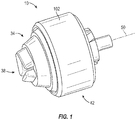
- FIG. 1 illustrates a chuck assembly 10 for connection to an output member (e.g., a spindle; not shown) of a rotary power tool (e.g., a drill, impact driver, etc.; not shown).
- the chuck assembly 10 is configured to quickly receive and secure tool bits with standardized shanks of at least two different predetermined, nominal sizes.
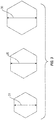
- the illustrated chuck assembly 10 is configured to receive a tool bit 14 with a hexagonal shank 18 that can be any one of a first nominal size 22, a second nominal size 26, and a third nominal size 30 ( FIGS. 2 and 3 ).
- the first, second, and third nominal sizes 22, 26, 30 are preferably standard or commonly-used hexagonal shank sizes, such as 1/4-inch, 3/8-inch, and 7/16-inch.
- the chuck assembly 10 may be configured to receive tool bits with other types of shanks (e.g., square, three-flat, round, etc.).
- the chuck assembly 10 may be configured to receive tool bits of four or more different nominal sh
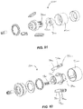
- the chuck assembly 10 includes a chuck body 34, a plurality of jaws 38, a collar 42, and a split ring 46.
- the chuck body 34 is coupled for co-rotation with the output member of the power tool about a central axis 50.
- the chuck body 34 includes a head portion 54, a shaft portion 58, and a plurality of slots 62 in which the respective jaws 38 are slidably received.
- Each of the slots 62 is oriented at an oblique angle relative to the central axis 50.
- the shaft portion 58 includes a plurality of externally-threaded sections 66 disposed circumferentially about the shaft portion 58 between the slots 62 ( FIG. 5 ).
- Each threaded section 66 includes a plurality of helical thread segments 70 situated adjacent one another along the axis 50.
- the illustrated thread segments 70 project outwardly from the shaft portion 58; however, in other embodiments, the thread segments 70 may be defined by slots cut into the shaft portion 58.
- the number of thread segments 70 is at least equal to the predetermined number of tool bit shank sizes that the chuck assembly 10 is adapted to receive.
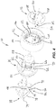
- each threaded section 66 includes three thread segments 70: a first thread segment 70a, a second thread segment 70b, and a third thread segment 70c ( FIGS. 8A-8C ).
- additional thread segments 70 may be provided.
- the relative axial position of each of the thread segments 70a, 70b, 70c corresponds with each particular shank size able to be accommodated by the chuck assembly 10.
- the illustrated chuck assembly 10 includes three jaws 38; however, the chuck assembly 10 may include any number of jaws 38.
- Each of the jaws 38 has a front portion or tip 74 and an oblique outer surface 78 extending rearward from the tip 74.
- Each of the jaws 38 may include a generally U-shaped engagement portion 82 at the rear end of the jaw 38 opposite the tip 74.
- the engagement portion 82 includes opposing first and second engagement surfaces 86, 90 that define a groove 94 therebetween.
- a base surface 98 extending between the first and second engagement surfaces 86, 90 forms the bottom of the groove 94.
- the first and second engagement surfaces 86, 90 extend perpendicular to the central axis 50, and the base surface 98 extends parallel to the central axis 50.
- the collar 42 is received on the shaft portion 58 of the chuck body 34 and is rotatable and axially movable relative to the chuck body 34.
- the illustrated collar 42 includes a user-manipulable outer surface 102 and an inner annular wall 106.
- the annular wall 106 includes a front side 110 ( FIG. 5 ), a back side 114 ( FIG. 4 ), and an interior side 118 that extends between the front side 110 and the back side 114.
- the illustrated collar 42 includes a skirt portion 51 extending rearward from the annular wall 106 ( FIGS. 6 and 7 ).
- the interior of the skirt portion 51 defines a recess 53 that may receive an annular projecting portion (not shown) formed, for example, as a part of the chuck body 34 or as a part of a front end assembly of a power tool.
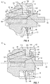
- the annular wall 106 extends into the groove 94 of each jaw 38 such that the front side 110 of the annular wall 106 opposes the first engagement surface 86. Accordingly, when the collar 42 is moved forward (i.e. to the left in FIGS. 6 and 7 ) relative to the chuck body 34, the front side 110 of the annular wall 106 bears against the first engagement surface 86 to move the jaws 38 forward. As the jaws 38 move forward, they also move radially inward due to the oblique orientation of the slots 62. Forward movement of the collar 42 is limited by engagement between the front side 110 of the annular wall 106 and the head portion 54 of the chuck body 34 ( FIG. 6 ).
- the collar 42 further includes a plurality of inwardly-projecting helical thread segments 122 provided on the interior side 118 of the annular wall 106.
- the thread segments 112 project from the interior side 118; however, in other embodiments, the thread segments 112 may be defined by slots cut into the interior side 118.
- the thread segments 122 on the collar 42 are selectively engageable with the thread segments 70 on the chuck body 34, and the collar 42 is rotatable relative to the chuck body 34 to clamp the shank 18 of the tool bit 14 between the jaws 38.
- the split ring 46 is received on the shaft portion 58 of the chuck body 34 adjacent the back side 114 of the collar's annular wall 106.
- the split ring 46 is axially movable with the collar 42 relative to the chuck body 34.
- the split ring 46 includes a front side 126, a back side 130, a plurality of inwardly-projecting, circumferentially spaced retaining tabs 134 and a plurality of guide tabs 138 that extend from the back side 130.
- the split ring 46 further includes a gap 142 that allows for resilient expansion of the split ring 46 (e.g., during assembly of the chuck assembly 10). Best illustrated in FIGS.
- the front side 126 of the split ring 46 opposes the back side 114 of the collar's annular wall 106. Accordingly, when the collar 42 is moved rearward (i.e. to the right in FIGS. 6 and 7 ) relative to the chuck body 34, the back side 114 of the annular wall 106 bears against the front side 126 of the split ring 46 to move the split ring 46 rearward with the collar 42.
- the retaining tab 134 bears against the second engagement surface 90 to also move the jaws 38 rearward. As the jaws 38 move rearward, they move radially-outward due to the oblique orientation of the slots 62.
- Rearward movement of the collar 42 and the split ring 46 is limited by engagement of the base surface 98 with the retaining tabs 134 ( FIG. 7 ). Rearward movement of the collar 42 and the split ring 46 may also be limited by engagement between the collar 42 and a portion of the power tool (e.g., the power tool housing; not shown).
- the guide tabs 138 are configured to overlie and engage the threaded sections 66 of the chuck body 34 to maintain the split ring 46 in alignment with the central axis 50.
- the front side 126 of the split ring 46 optionally includes a pair of axially-extending nubs or detents 146 ( FIG. 5 ).
- the detents 146 are received in respective arcuate grooves 150 formed in the back side 114 of the annular wall 106 ( FIG. 4 ). Accordingly, relative rotation between the collar 42 and the split ring 46 is limited by one or both of the detents 146 engaging an end of the corresponding arcuate groove 150.
- the arcuate grooves 150 are provided with a ridged or knurled texture, which may provide tactile and/or audible feedback when the collar 42 is rotated relative to the split ring 46. The texture may also increase friction between the detents 146 and the grooves 150 to provide the collar 42 with a desired level of rotational resistance.
- the grooves 150 may be generally smooth.
- a user rotates the collar 42 (e.g., by about 60 degrees in the illustrated embodiment) to disengage the thread segments 122 on the collar 42 from the thread segments 70 on the chuck body 34. This occurs when the thread segments 122 are aligned with the slots 62, rather than with the thread segments 70. With the thread segments 122, 70 disengaged, the collar 42, split ring 46, and jaws 38 are freely axially movable along the chuck body 34. Next, the user pushes the collar 42 back toward its rearmost position ( FIG. 7 ), corresponding with the open-most position of the jaws 38.
- the collar 42 may be biased forward by a spring (not shown; the spring may act, for example, on the back side 130 of the split ring 46).
- the user begins to rotate the collar 42 in a tightening direction. Because the axial position of the first thread segments 70a corresponds with the first nominal shank size 22, the collar thread segments 122 engage the front of the first thread segments 70a ( FIG. 8A ). The engagement of the thread segments 122, 70a advances the collar 42 forward, which in turn pushes the jaws 38 forward and inward to exert a clamping force on the shank 18, thereby securing the tool bit 14 in the chuck assembly 10.
- the user rotates the collar 42 in a loosening direction opposite the tightening direction to disengage the thread segments 122 on the collar 42 from the thread segments 70 on the chuck body 34.
- Rotating the collar 42 in the loosening direction also releases the clamping force and permits removal of the existing tool bit 14.
- the collar 42, split ring 46, and jaws 38 are freely axially movable along the chuck body 34. The user pushes the collar 42 back toward its rearmost position ( FIG. 7 ), corresponding with the open-most position of the jaws 38.
- the user positions the shank 18 of the second nominal size 26 between the jaws 38, and then moves the collar 42 forward until the jaws 38 come into contact with the shank 18.
- the user begins to rotate the collar 42 in the tightening direction. Because the axial position of the second thread segments 70b corresponds with the second nominal shank size 26, the collar thread segments 122 engage the front of the second thread segments 70b ( FIG. 8B ).
- the engagement of the thread segments 122, 70b advances the collar 42 forward, which in turn pushes the jaws 38 forward and inward to exert a clamping force on the shank 18, thereby securing the tool bit 14 in the chuck assembly 10.
- the user rotates the collar 42 in the loosening direction opposite to disengage the thread segments 122 on the collar 42 from the thread segments 70 on the chuck body 34.
- Rotating the collar 42 in the loosening direction also releases the clamping force and permits removal of the existing tool bit 14.
- the collar 42, split ring 46, and jaws 38 are freely axially movable along the chuck body 34. The user pushes the collar 42 back toward its rearmost position ( FIG. 7 ), corresponding with the open-most position of the jaws 38.
- the user positions the shank 18 of the third nominal size 30 between the jaws 38, and then moves the collar 42 forward until the jaws 38 come into contact with the shank 18.
- the user begins to rotate the collar 42 in the tightening direction. Because the axial position of the third thread segments 70c corresponds with the third nominal shank size 30, the collar thread segments 122 engage the front of the third thread segments 70c ( FIG. 8C ).
- the engagement of the thread segments 122, 70c advances the collar 42 forward, which in turn pushes the jaws 38 forward and inward to exert a clamping force on the shank 18, thereby securing the tool bit 14 in the chuck assembly 10.
- FIGS. 9-13C illustrate a chuck assembly 300 according to another embodiment.
- the chuck assembly 300 is configured for connection to an output member of a rotary power tool and is able to quickly receive and secure tool bits with standardized shanks of at least two different predetermined, nominal sizes.
- the illustrated chuck assembly 300 is configured to receive a tool bit 14 with a hexagonal shank 18 of the first nominal size 22, the second nominal size 26, and the third nominal size 30 ( FIGS. 2 and 3 ).
- the chuck assembly 300 may be configured to receive tool bits with other types of shanks (e.g., square, three-flat, round, etc.).
- the chuck assembly 300 may be configured to receive tool bits of four or more different nominal shank sizes.
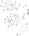
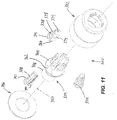
- the chuck assembly 300 includes a chuck body 334, a plurality of jaws 338, a collar 342, and a retaining ring 346.
- the chuck body 334 is coupled for co-rotation with the output member of the power tool about a central axis 350.
- the chuck body 334 includes a head portion 354, a shaft portion 358, and a plurality of slots 362 in which the respective jaws 338 are slidably received.
- Each of the slots 362 is preferably oriented perpendicular to the central axis 350 such that the jaws 338 are movable along the slots 362 toward and away from the central axis 350.
- the illustrated chuck assembly 300 includes three jaws 338; however, the chuck assembly 300 may include any number of jaws 338.
- Each of the jaws 338 has an angled front portion or tip 374, an oblique outer side 378 extending rearward from the tip 374, a tool-engaging side 379 extending rearward from the tip 374, and a rear side 380 extending between the oblique outer side 378 and the tool-engaging side 379.
- the tool-engaging side 379 is configured to engage the shank 18 of the tool bit 14 when the bit 14 is received between the jaws 338.
- each jaw 338 is formed with a plurality of steps 382, each defined by a discrete flat surface 386 (or tread) oriented generally parallel to the central axis 350 and an adjacent inclined surface 390 (or riser) oriented at an oblique angle relative to the central axis 350 ( FIG. 12 ).
- the flat surfaces 386 may be formed with a draft angle such that the flat surfaces 386 do not extend parallel to the central axis 350 but rather define an angle with the central axis 350 that is smaller than the oblique angle of the inclined surfaces 390.
- the illustrated jaws 338 also include laterally-extending ears 391 that are received in the slots 362 to guide the jaws 338 along the slots 362 ( FIG. 11 ).
- each of the jaws 338 further includes a bore 392 extending through the rear side 380 ( FIG. 12 ).
- the bore 392 intersects the tool-engaging side 379 to define an aperture 393 in the tool-engaging side 379.
- a detent 394 e.g., a ball bearing
- the aperture 393 has a diameter at least slightly smaller than a diameter of the detent 394 such that the detent 394 cannot pass through the aperture 393.
- a plug 395 is provided in the bore 392 at the rear side 380, and a spring 396 is disposed between the plug 395 and the detent 394 to bias the detent 394 toward the aperture 393.
- the detent 394 of each jaw 338 is engageable with a groove 397 formed in the shank 18 of the tool bit 14 ( FIG. 2 ) to axially retain the tool bit 14 in the chuck assembly 300.
- one or more of the jaws 338 may omit the bore 392 and detent components 394, 395, 396.
- one or more of the jaws 338 may be substituted with an alternative jaw 338' illustrated in FIG. 14 .
- the alternative jaw 338' includes a projecting rib 398 extending laterally along the tool-engaging side 379. Like the detent 394, the projecting rib 398 is engageable with the groove 397 in the shank 18 ( FIG. 2 ) to axially retain the tool bit 14 in the chuck assembly 300.
- the collar 342 is received on the shaft portion 358 of the chuck body 334 and is coupled for co-rotation with the chuck body 334.
- the illustrated collar 342 includes a user-manipulable outer surface 402 and an angled inner surface 406 that is provided with a plurality of stepped regions 410.
- the stepped regions 410 each include a plurality of steps 416, each defined by a discrete flat surface 420 (or tread) oriented generally parallel to the central axis 350 and an adjacent inclined surface 424 (or riser) oriented at an oblique angle relative to the central axis 350 ( FIG. 12 ).
- the flat surfaces 420 may be formed with a draft angle such that the flat surfaces 420 do not extend parallel to the central axis 350 but rather define an angle with the central axis 350 that is smaller than the oblique angle of the inclined surfaces 424.
- the collar 342 is axially movable relative to the chuck body 334 such that the steps 416 on the collar 342 are engageable with the steps 382 on the jaws 338 in a plurality of predetermined positions ( FIGS. 13A-13C ), each corresponding with a different nominal shank size.
- the retaining ring 346 is fixed to the rear of the collar 342 (e.g., via press-fitting) such that the retaining ring 346 is axially movable with the collar 342 along the chuck body 334.
- the retaining ring 346 is engageable with a shoulder 428 formed on the chuck body 334 to limit axial movement of the collar 342 to a forward-most position illustrated in FIG. 12 .
- a biasing member 432 which is a coil spring in the illustrated embodiment, extends between a flange 436 on the chuck body 334 and the retaining ring 346 to bias the collar 342 rearward.
- a user pulls the collar 342 forward (i.e. to the left in FIGS. 12-13C ) along the central axis 350, toward the forwardmost position illustrated in FIG. 12 .
- the user inserts the shank 18 of the bit 14 between the jaws 338.
- the rear end of the shank 18 engages the angled front portions 374 of the jaws 338 to spread the jaws radially outward to accommodate the shank 18.
- the detents 394 engage the groove 397 to axially retain the bit 14 ( FIG. 12 ).
- the user can then release the collar 342, which moves rearward under the influence of the biasing member 432.
- the inclined surfaces 424 of the collar steps engage and slide along the inclined surfaces 390 of the steps 382 on the jaws 338 until the collar 342 reaches a first position ( FIG. 13A ) corresponding with the first nominal size 22.
- a first plurality of steps 416a on the collar 342 engages the steps 382 on the jaws 338.
- the jaws 338 are prevented from moving radially outwardly by the engagement between the flat surfaces 386, 420. Accordingly, the tool bit 14 is radially and axially retained within the chuck assembly 300.
- the user pulls the collar 342 forward along the central axis 350, toward the forward-most position illustrated in FIG. 12 . This permits the jaws 338 to move radially outward, releasing the existing bit 14.
- the user inserts the shank 18 of the replacement bit 14 between the jaws 338. The rear end of the shank 18 engages the angled front portions 374 of the jaws 338 to spread the jaws radially outward to accommodate the shank 18.
- the detents 394 engage the groove 397 to axially retain the bit 14. The user can then release the collar 342, which moves rearward under the influence of the biasing member 432.
- the inclined surfaces 424 of the collar steps engage and slide along the inclined surfaces 390 of the steps 382 on the jaws 338 until the collar 342 reaches a second position ( FIG. 13B ) corresponding with the second nominal size 26.
- a second plurality of steps 416b on the collar 342 engages the steps 382 on the jaws 338.
- the second plurality of steps 416b includes a greater number of steps 416 than the first plurality of steps 416a.
- the jaws 338 are prevented from moving radially outwardly by the engagement between the flat surfaces 386, 420. Accordingly, the tool bit 14 is radially and axially retained within the chuck assembly 300.
- the user pulls the collar 342 forward along the central axis 350, toward the forwardmost position illustrated in FIG. 12 . This permits the jaws 338 to move radially outward, releasing the existing bit 14.
- the user inserts the shank 18 of the replacement bit 14 between the jaws 338. The rear end of the shank 18 engages the angled front portions 374 of the jaws 338 to spread the jaws radially outward to accommodate the shank 18.
- the detents 394 engage the groove 397 to axially retain the bit 14. The user can then release the collar 342, which moves rearward under the influence of the biasing member 432.
- the inclined surfaces 424 of the collar steps engage and slide along the inclined surfaces 390 of the steps 382 on the jaws 338 until the collar 342 reaches a third position ( FIG. 13C ) corresponding with the third nominal size 30.
- a third plurality of steps 416c on the collar 342 engages the steps 382 on the jaws 338.
- the third plurality of steps 416c includes a greater number of steps 416 than both the first plurality of steps 416a and the second plurality of steps 416b.
- the jaws 338 are prevented from moving radially outwardly by the engagement between the flat surfaces 386, 420. Accordingly, the tool bit 14 is radially and axially retained within the chuck assembly 300.
- FIG. 15 illustrates a portion of a chuck assembly 500 according to another embodiment.
- the chuck assembly 500 is similar to the chuck assembly 300 described above with reference to FIGS. 9-13C . Accordingly, the following description focuses primarily on differences between the chuck assembly 500 and the chuck assembly 300. In addition, features and elements of the chuck assembly 500 corresponding with features and elements of the chuck assembly 300 are given like reference numbers plus 200.
- each of the jaws 538 of the chuck assembly 500 has an oblique outer side 578 formed with a plurality of steps 582, each defined by a discrete flat surface 586 oriented generally parallel to the central axis 550 and an adjacent inclined surface 590 oriented at an oblique angle relative to the central axis 550.
- the flat surfaces 586 may be formed with a draft angle such that the flat surfaces 586 do not extend parallel to the central axis 550 but rather define an angle with the central axis 550 that is smaller than the oblique angle of the inclined surfaces 590.
- the illustrated steps 582 include a first flat surface 586a adjacent the tip 574 of the jaw 538, second and third flat surfaces 586b, 586c proximate the first flat surface 586a.
- a fourth flat surface 586d is located adjacent the rear side 580 of the jaw 538.
- the oblique outer side 578 of each jaw 538 also includes a gap or stairless region 589 between the third flat surface 586c and the fourth flat surface 586d.
- the steps 582 may include any number of flat surfaces 586 arranged on either side of the gap 589.
- the angled inner surface 606 of the collar 542 is provided with a plurality of steps 616, each defined by a discrete flat surface 620 oriented generally parallel to the central axis 550 and an adjacent inclined surface 624 oriented at an oblique angle relative to the central axis 350.
- the flat surfaces 620 may be formed with a draft angle such that the flat surfaces 620 do not extend parallel to the central axis 550 but rather define an angle with the central axis 550 that is smaller than the oblique angle of the inclined surfaces 624.
- the illustrated steps 616 include first, second, third, and fourth flat surfaces 620a, 620b, 620c, 620d.
- the first flat surface 620a is disposed adjacent a front end of the collar 542, and the fourth flat surface 520d is disposed proximate a rear end of the collar 542.
- the angled inner surface 606 of the collar 542 also includes a gap or stairless region 689 between the first flat surface 620a and the second flat surface 620b.
- the steps 616 may include any number of flat surfaces 620 arranged on either side of the gap 689.
- each jaw 538 When securing a tool bit 14 of the second nominal shank size 26 ( FIG. 3 ), the second flat surface 586b of each jaw 538 engages the corresponding first flat surface 620a of the collar 542, and the fourth flat surface 586d of each jaw 538 engages the corresponding third flat surface 620c of the collar 542 ( FIG. 16B ).
- the first flat surface 586a of each jaw 538 extends beyond the front of the collar 542, and the third flat surface 586c of each jaw 538 is positioned in the gap 689.
- the first flat surface 586a of each jaw 538 engages the corresponding first flat surface 620a of the collar 542, and the fourth flat surface 586d of each jaw 538 engages the corresponding fourth flat surface 620d of the collar 542 ( FIG. 16C ).
- the remaining flat surfaces 586b, 586c of the jaw 538 are positioned in the gap 689, and the remaining flat surfaces 620b, 620c of the collar 542 are positioned in the gap 589.
- the collar 542 engages each of the jaws 538 in the radial direction at only two discrete contact areas for each predetermined nominal shank size 22, 26, 30.
- the chuck assembly 500 may therefore permit greater tolerance variations on the jaws 538 and/or the collar 542 compared to the chuck assembly 300, for example, and/or provide better fitment of the jaws 538 and collar 542.
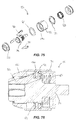
- FIGS. 17 and 18 illustrate a chuck assembly 700 according to another embodiment.
- the chuck assembly 700 is similar to the chuck assembly 300 described above with reference to FIGS. 9-13C . Accordingly, the following description focuses primarily on differences between the chuck assembly 700 and the chuck assembly 300. In addition, features and elements of the chuck assembly 700 corresponding with features and elements of the chuck assembly 300 are given like reference numbers plus 400.
- the chuck assembly 700 includes a retaining ring 746 that has a cupped shape such that the retaining ring 746 defines an inner flange portion 747 and an outer flange portion 748 that is offset from the inner flange portion 747 along the central axis 750.
- the outer flange portion 748 is fixed within the collar 742 (e.g., via press-fitting) such that the retaining ring 746 is axially movable with the collar 742 along the chuck body 734.
- the retaining ring 746 is engageable with a shoulder 828 formed on the chuck body 734 to limit axial movement of the collar 742 to a forward-most position illustrated in FIG. 18 .
- the illustrated collar 742 includes a skirt 751 extending rearward from the outer flange portion 748 of the retaining ring 746.
- An annular recess 753 is defined between the skirt 751 and the retaining ring 746.
- the annular recess 753 may receive an annular projecting portion 755 formed, for example, as a part of the chuck body 734 or as a part of a front end assembly of a power tool.
- FIG. 19 illustrates a portion of a chuck assembly 800 according to another embodiment.
- the chuck assembly 800 is similar to the chuck assembly 300 described above with reference to FIGS. 9-13C . Accordingly, the following description focuses primarily on differences between the chuck assembly 800 and the chuck assembly 300. In addition, features and elements of the chuck assembly 800 corresponding with features and elements of the chuck assembly 300 are given like reference numbers plus 500.
- Each of the jaws 838 of the chuck assembly 800 has a plurality of steps 882.
- the steps 882 are each defined by a discrete flat surface 886 oriented generally parallel to the central axis 850 and an adjacent inclined surface 890 oriented at an oblique angle relative to the central axis 850.
- the illustrated steps 882 include a first flat surface 886a adjacent the tip 874 of the jaw 838 and a last flat surface 886d is located adjacent the rear side 880 of the jaw 838.
- a first inclined surface 890a extends from the first flat surface 886a, and a last inclined surface 890d extends from the last flat surface 886d.
- the flat surfaces 886 may be formed with a draft angle such that the flat surfaces 886 do not extend parallel to the central axis 850 but rather define an angle with the central axis 850.
- the inside of the collar 842 is provided with a plurality of steps 916.
- the steps 916 are each defined by a discrete flat surface 920 oriented generally parallel to the central axis 850 and an adjacent inclined surface 924 oriented at an oblique angle relative to the central axis 850.
- the illustrated steps 916 include a first flat surface 920a is disposed adjacent a front end of the collar 842, and a last flat surface 920d is disposed proximate a rear end of the collar 842.
- a first inclined surface 924a extends from the first flat surface 920a, and a last inclined surface 924d extends from the last flat surface 920d.
- the flat surfaces 920 may be formed with a draft angle such that the flat surfaces 920 do not extend parallel to the central axis 850 but rather define an angle with the central axis 850.
- the first flat surface 920a of the collar 842 and the last flat surface 886d of the jaws 838 are taller than the other flat surfaces 920 and 886, respectively.
- the inclined surface 924 adjacent the first flat surface 920a and the inclined surface 890 adjacent the last flat surface 886d are longer than the other inclined surfaces 924, 890 of the collar 842 and the jaws 838, respectively.
- the collar 842 engages each of the jaws 838 in the radial direction at as few as two discrete contact areas for each predetermined nominal shank size 22, 26, 30.
- the first inclined surfaces 890a, 924a are located behind the first flat surfaces 886a, 920a such that the inclined surfaces 890a, 924a and flat surfaces 886a, 920a intersect at an angle pointing generally radially inward.
- the last inclined surfaces 890d, 924d are located in front of the last flat surfaces 886d, 920d such that the inclined surfaces 890d, 924d and flat surfaces 886d, 920d intersect at an angle pointing generally radially outward.
- the steps 882, 916 can be configured in a variety of different ways such that adjacent surfaces 886, 890, 920, 924 may intersect at an angle pointing generally radially outward or inward.
- FIG. 20 illustrates a portion of a chuck assembly 1000 according to another embodiment.
- the chuck assembly 1000 is similar to the chuck assembly 800 described above with reference FIG. 19 . Accordingly, the following description focuses primarily on differences between the chuck assembly 1000 and the chuck assembly 800. In addition, features and elements of the chuck assembly 1000 corresponding with features and elements of the chuck assembly 800 are given like reference numbers plus 200.
- Each of the jaws 1038 of the chuck assembly 1000 has a front inclined surface 1090a extending from the tip 1074 and disposed in front of the first flat surface 1086a.
- the front inclined surface 1090a and the first flat surface 1086a intersect at an angle pointing generally radially outward.
- Each of the jaws 1038 also includes a rear inclined surface 1090d extending from the last flat surface 1086d and proximate the rear side 1080.
- the rear inclined surface 1090d and the last flat surface 1086d intersect at an angle pointing generally radially inward.
- the steps 1082 can be configured in a variety of different ways such that adjacent surfaces 1086, 1090 may intersect at an angle pointing generally radially outward or inward.
- the collar 1042 includes a front inclined surface 1124a and a rear inclined surface 1124d.
- the front inclined surface 1090a of each jaw 1038 engages the front inclined surface 1124a of the collar 1042
- the rear inclined surface 1090d of each jaw 1038 engages the rear inclined surface 1124d of the collar 1042.
- the inclined surfaces 1090a, 1090d, 1124a, 1124d are engageable with the other inclined surfaces 1090, 1124 that form the steps 1082, 1116 of the jaws 1038 and the collar 1042, respectively, in other positions of the collar 1042.
- the additional engagement provided by the inclined surfaces 1090a, 1090d, 1124a, 1124d may improve the alignment of the jaws 1038.
- FIG. 21 illustrates an alternative jaw 1238 that may be used, for example, with any of the chuck assemblies described herein.
- the jaw 1238 includes laterally-extending ears 1291 or wings at the rear side 1280 of the jaw 1238.
- the ears 1291 may be received in slots (e.g., the slots 362 described above with reference to FIG. 11 ) to guide radial movement of the jaw 1238.
- Each of the ears 1291 includes a flat surface 1286 and an adjacent inclined surface 1290.
- the flat surface 1286 and the inclined surface 1290 act as the final step 1282, allowing the overall height of the jaw 1238 (and, therefore, the overall diameter of a corresponding chuck assembly) to be reduced.
- FIG. 22 illustrates an alternative jaw 1338 that may be used, for example, with any of the chuck assemblies described herein.
- the jaw 1338 includes laterally-extending ears 1391 or wings proximate the tip 1374. Placement of the ears 1391 proximate the tip 1374 may enhance the strength of the jaw 1338 and/or the corresponding chuck body.
- the illustrated jaw 1338 further includes lateral slots 1393 located proximate the rear side 1380 of the jaw 1338. The slots 1393 receive corresponding projections (not shown) to guide radial movement of the jaw 1338.
- Each of the ears 1391 includes a flat surface 1386 and an adjacent inclined surface 1390. The flat surface 1386 and the inclined surface 1390 act as one of the steps 1382, allowing the overall height of the jaw 1338 (and, therefore, the overall diameter of a corresponding chuck assembly) to be reduced.
- FIG. 23 illustrates a portion of a chuck assembly 1400 according to another embodiment.
- the chuck assembly 1400 is similar to the chuck assembly 300 described above with reference to FIGS. 9-13C . Accordingly, the following description focuses primarily on differences between the chuck assembly 1400 and the chuck assembly 300. In addition, features and elements of the chuck assembly 1400 corresponding with features and elements of the chuck assembly 300 are given like reference numbers plus 1100.
- Each of the jaws 1438 of the chuck assembly 1400 includes only two steps 1482, and the collar 1442 includes a greater number of steps 1516 than the jaws 1438.
- Each jaw has a first flat surface 1486a and a second flat surface 1486b.
- the first flat surface 1486a is engageable with first, second, or third flat surfaces 1590a-c of the collar 1442
- the second flat surface 1486b is engageable with fourth, fifth, or sixth flat surface 1590d-f of the collar 1442, depending on what size shank 18 ( FIG. 2 ) is inserted between the jaws 1438.
- FIG. 24 illustrates a portion of a chuck assembly 1600 according to another embodiment.
- the chuck assembly 1600 is similar to the chuck assembly 1400 described above with reference to FIG. 23 . Accordingly, the following description focuses primarily on differences between the chuck assembly 1600 and the chuck assembly 1400. In addition, features and elements of the chuck assembly 1600 corresponding with features and elements of the chuck assembly 1400 are given like reference numbers plus 200.
- the collar 1642 includes a first plurality of steps 1716a and a second plurality of steps 1716b.
- the second plurality of steps 1716b is provided on an insert 1719 disposed within the collar 1642.
- the insert 1719 may be secured within the collar 1642 in a variety of ways, such as by press-fitting.
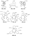
- FIGS. 25A-C illustrate an alternative jaw 1838 that may be used, for example, with any of the chuck assemblies described herein.
- the jaw 1838 includes a projecting rib 1898 extending laterally along the tool-engaging side 1879.
- the rib 1898 is engageable with the groove 397 in the shank 18 ( FIG. 2 ) to axially retain the tool bit 14 in the chuck assembly.
- the rib 1898 has an arcuate shape that provides a greater contact area between the rib 1898 and the tool bit 14. This advantageously reduces stress on the rib 1898.
- FIGS. 26A-C illustrate an alternative jaw 1938 that may be used, for example, with any of the chuck assemblies described herein.
- the jaw 1938 includes a retaining recess 1999 extending laterally across the tool-engaging side 1979.
- the retaining recess 1999 may receive a retaining element (not shown), such as a cylindrical pin.
- the retaining element is engageable with the groove 397 in the shank 18 ( FIG. 2 ) to axially retain the tool bit 14 in the chuck assembly.
- the retaining element may be held within the retaining recess 1999 by via any suitable means, such as by a press-fit, welding, or chemical bonding. Alternatively, the retaining element may be held within the recess 1999 by other components of a chuck assembly. In some embodiments, the retaining element may be removable and replaceable. In some embodiments, the retaining element may have different material properties from the remainder of the jaw 1938. For example, the retaining element may have a higher hardness, a lower coefficient of friction, and the like.
- FIGS. 27A-C illustrate an alternative jaw 2038 that may be used, for example, with any of the chuck assemblies described herein.
- the jaw 2038 includes a bore 2092 extending through the rear side 2080 ( FIG. 27B ).
- the bore 2092 intersects the tool-engaging side 2079 to define an aperture 2093 in the tool-engaging side 2079.
- the bore 2092 can accommodate a variety of retaining elements.
- a detent 2094 (e.g., a ball bearing) is disposed within the bore 2092 and projects through the aperture 2093.
- the aperture 2093 may be circular, or may have other, non-circular shapes.
- the aperture 2093 has a diameter (or maximum width dimension) at least slightly smaller than a diameter of the detent 2094 such that the detent 2094 cannot pass through the aperture 2093.
- a plug 2095 is provided in the bore 2092 at the rear side 2080, and a compressible element 2096a is disposed between the plug 2095 and the detent 2094 to bias the detent 2094 toward the aperture 2093.
- the plug 2095 may be a snap ring or a solid part pressed into the bore 2092.
- the detent 2094 is engageable with a groove 397 formed in the shank 18 of the tool bit 14 ( FIG. 2 ) to axially retain the tool bit 14 in the chuck assembly.
- the compressible element 2096a is replaced by a coil spring 2096b, and the plug 2095 is omitted.
- the spring 2096b may be retained, for example, by a washer (not shown) held against the rear side 2080 or by any other suitable means (including the plug 2095).
- the detent 2094 is a pin with a chamfered end 2094a
- the plug 2095 is made of a compressible material such that the plug 2095 both retains the detent 2094 within the bore 2092 and biases the detent 2094 toward the aperture 2093.
- FIGS. 31A-C illustrate an alternative jaw 2138 that may be used, for example, with any of the chuck assemblies described herein.
- the jaw 2138 includes a V-shaped groove 2177 in the tool-engaging side 2179.
- the groove 2177 engages adjacent sides of the shank 18 ( FIG. 2 ) and, in some embodiments, allows the tool bit 14 to be securely held with only two jaws 2138. In other embodiments, any number of jaws 2138 may be used in a chuck assembly.
- FIG. 32 illustrates a chuck assembly 2200 according to another embodiment.
- the chuck assembly 2200 includes jaws 2238 that are each movable outward along an axis 2259 to accommodate differently sized shanks 18 ( FIG. 2 ).
- the axis 2259 forms an acute included angle with a radial axis 14a of the bit 14 ( FIG. 32 ).
- FIG. 33 illustrates a chuck assembly 2300 according to another embodiment.
- the chuck assembly 2300 includes jaws 2338 that are each partially offset from the drive surfaces 19 of the hexagonal shank 18, in directions parallel to the respective drive surfaces 19. In other words, each of the jaws 2338 extends beyond an outer edge of the associated drive surface 19 in the radially outward direction.
- the direction of offset may be selected to reduce stresses on the jaws 2338 when the chuck assembly 2300 rotates in a particular direction.
- FIG. 34 illustrates a chuck assembly 2400 according to another embodiment.
- the chuck assembly 2400 includes jaws 2438 that are each movable outward along an arcuate path 2463 to accommodate differently sized shanks 18 ( FIG. 2 ).
- FIG. 35 illustrates a chuck assembly 2500 according to another embodiment.
- the chuck assembly 2500 includes jaws 2538, each with a tool engaging side 2579 oriented at an oblique angle.
- the oblique orientation of the tool engaging sides 2579 may provide improved torque transfer to the tool bit 14 in a rotational direction 2581 (preferably the "forward" rotational direction of the tool bit 14).
- FIG. 36 illustrates an alternative jaw 2638 that may be used, for example, with any of the chuck assemblies described herein.
- the jaw 2638 includes a tool engaging side 2679 and a rear side 2680 oriented at an oblique angle with respect to the tool engaging side 2679.
- the rear side 2680 is angled rearward, such that engagement of the rear side 2680 with the chuck body (e.g., the chuck body 334; FIG. 12 ) causes the jaw 2638 to move radially outward and axially rearward (along the central axis 2650) in response to insertion or removal of the tool bit 14 ( FIG. 2 ).
- the rear side 2680 may be angled forward. The oblique angle may be selected to facilitate insertion/removal of the tool bit 14, engagement and alignment with the groove 397, or to increase or decrease a contact area between the jaw 2638 and collar (e.g., the collar 342; FIG. 10 ).
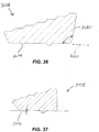
- FIG. 37 illustrates an alternative jaw 2738 that may be used, for example, with any of the chuck assemblies described herein.
- the jaw 2738 includes a tool engaging side 2779 that is pitched or inclined slightly relative to the central axis 2750 when the jaw 2738 is engaged with a collar (e.g., the collar 342; FIG. 12 ).
- the pitch angle of the tool engaging side 2779 may be positive or negative, which may shift radial loads exerted by the tool bit 14 on the jaw 2738 forward or rearward, respectively.
- FIG. 39 illustrates a portion of a chuck assembly 2800 according to another embodiment.
- the chuck assembly 2800 includes a chuck body 2834 with slots 2862 that receive the jaws 2838.
- Each slot 2862 includes a first wall 2862a engageable with a first lateral side 2839a of the associated jaw 2838 and a second wall 2862b engageable with a second lateral side 2839b of the jaw 2838.
- the illustrated slots 2962 are formed with a draft angle 2863, such that each wall 2862a, 2862b forms an angle with the central axis 2850. In the illustrated embodiment, the draft angle 2863 is about 0.5 degrees.
- the lateral sides 2839a, 2839b of the jaw 2838 also are formed with a corresponding draft angle 2865 of about 0.5 degrees.
- the walls 2862a, 2862b and lateral sides 2839a, 2839b may additionally or alternatively be formed with a draft angle in the radial direction.
- the illustrated jaw 2838 further includes tapered portions 2841a, 2841b extending from the respective first and second lateral sides 2839a, 2839b to the tip 2874.
- the tapered portions 2841a, 2841b are angled inward toward a longitudinal center plane of the jaw 2838.
- the tapered portions 2841a, 2841b reduce the area of the lateral sides 2839a, 2839b that is in contact with the walls 2862a, 2862b of the slot 2862. This may reduce sliding friction between the jaws 2838 and the slot 2862 and direct stresses toward the rear, thicker side of the jaw 2838.
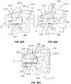
- FIGS. 40A-C illustrate a chuck assembly 2900 according to another embodiment.
- the chuck assembly 2900 is similar to the chuck assembly 300 described above with reference to FIGS. 9-13C . Accordingly, the following description focuses primarily on differences between the chuck assembly 2900 and the chuck assembly 300.
- features and elements of the chuck assembly 2900 corresponding with features and elements of the chuck assembly 300 are given like reference numbers plus 2600.
- Each of the jaws 2938 of the chuck assembly 2900 includes a projecting rib 2998 extending laterally along the tool-engaging side 2979.
- the ribs 2998 preferably have an arcuate shape and a rounded or tapered cross-section.
- the chuck assembly 2900 further includes a backstop or guide 2925 coupled to the chuck body 2934 behind the jaws 2938.
- the guide 2925 includes a tapered recess 2927 that engages a rear end 14b of the tool bit 14 when the tool bit 14 is fully inserted into the chuck assembly 2900.
- the guide 2925 is a screw that extends along the axis 2950, and the tapered recess 2927 is defined by a head of the screw.
- the guide 2925 may be integrally formed with the chuck body 2934. Due to the shape of the tapered recess 2927, bits 14 of different diameters will engage the recess 2927 at slightly different axial positions (e.g., as shown in FIGS. 40A-C ). This may facilitate retaining tool bits 14 with shank grooves 2997a, 2997b, 2997c having a variety of different widths or placements.
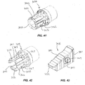
- FIG. 41 illustrates an alternative chuck body 3034 that may be used, for example, with any of the chuck assemblies described herein.
- the chuck body 3034 includes a plurality of prongs 3035 and jaw-receiving slots 3062 defined between adjacent prongs 3035.
- the prongs 3035 are interconnected at their front ends by a ring 3037.
- the slots 3062 are closed at the front end of the chuck body 3034 by the ring 3037.
- the ring 3037 may act as a structural element to strengthen the chuck body 3034 and, in some embodiments, may limit forward movement of jaws, a collar, or other components (not shown) carried by the chuck body 3034.
- the ring 3037 may be integrally formed with the prongs 3035 and/or the remainder of the chuck body 3034, or the ring may be a separate component fixed to the prongs 3035.
- FIG. 42 illustrates an alternative chuck body 3134 that may be used, for example, with any of the chuck assemblies described herein.
- the chuck body 3134 includes prongs 3135 and jaw-receiving slots 3162 defined between adjacent prongs 3135.
- Each of the slots 3162 includes opposing grooves 3167 configured to receive laterally-extending ears or wings of a jaw (not shown).
- the grooves 3167 are located proximate the center of the prongs 3135 in the illustrated embodiment; however, the grooves 3167 may alternatively be located elsewhere along the length of the prongs 3135.
- FIG. 43 illustrates an alternative jaw 3138 that may be used, for example, with any of the chuck assemblies described herein.
- the jaw 3138 includes laterally-extending ears 3191 between the rear side 3180 and the tip 3174 of the jaw 3138.
- the ears 3191 are generally centered between the rear side 3180 and the tip 3174, but the position of the ears 3191 may vary.
- the ears 3191 may be received in grooves (e.g., the grooves 3167 of the chuck body 3134; FIG. 42 ) to guide radial movement of the jaw 3138.
- Each of the ears 3191 includes a relief 3169 that may facilitate radial movement of the jaw 3138 and prevent the ears 3191 from binding in the grooves 3167.
- FIG. 44 illustrates an alternative chuck body 3234 that may be used, for example, with any of the chuck assemblies described herein.
- the chuck body 3234 is similar to the chuck body 3034 described above with reference to FIG. 41 , except the prongs 3235 have a smooth outer surface 3235a devoid of grooves or other features.
- the slots 3262 do not include opposing grooves.
- the jaws (not shown) used with the chuck body 3234 may include at least one laterally-extending flange engageable with the body 3234 at the periphery of the slots 3262 to limit movement of the jaws in a radially-inward direction.
- the chuck body 3234 may include a variety of reliefs, slots, grooves, and the like to control stress concentrations on the chuck body 3234.
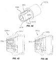
- FIGS. 45 and 46 illustrate alternative collars 3342a, 3342b that may be used, for example, with any of the chuck assemblies described herein.
- Each collar 3342a, 3342b includes a first annular projection 3343 extending radially inward at the front end of the collar 3342a, 3342b.
- the first annular projection 3343 protects the interior of the collar 3342a, 3342b.
- the collar 3342a, 3342b also includes a second annular projection 3345 extending radially outward proximate the middle of the collar 3342a, 3342b.
- the second annular projection 3345 may be grasped by a user to facilitate moving the collar 3342a, 3342b.
- the second annular projection 3345 increases the thickness and strength of the middle of the collar 3342a, 3342b where stresses may be highest.
- FIG. 47 illustrates a chuck assembly 3400 according to another embodiment.
- the chuck assembly 3400 is similar to the chuck assembly 300 described above with reference to FIGS. 9-13C . Accordingly, the following description focuses primarily on differences between the chuck assembly 3400 and the chuck assembly 300. In addition, features and elements of the chuck assembly 3400 corresponding with features and elements of the chuck assembly 300 are given like reference numbers plus 3100.
- the chuck assembly 3400 includes a sleeve 3404 surrounding a rear portion of the collar 3442.
- the sleeve 3404 may be coupled for co-rotation with the chuck body 3434, or the chuck body 3434 may be rotatable independently of the sleeve 3404.
- the collar 3442 is axially movable relative to the sleeve 3404 in the forward direction, and the sleeve 3404 may thus at least partially cover any gap formed between a rear end of the collar 3442 and, for example, a front end of a power tool housing (not shown).
- the sleeve 3404 may also perform other functions on the power tool, such as clutch adjustment and/or mode selection.
- FIG. 48 illustrates a chuck assembly 3500 according to another embodiment.
- the chuck assembly 3500 is similar to the chuck assembly 300 described above with reference to FIGS. 9-13C . Accordingly, the following description focuses primarily on differences between the chuck assembly 3500 and the chuck assembly 300. In addition, features and elements of the chuck assembly 3500 corresponding with features and elements of the chuck assembly 300 are given like reference numbers plus 3200.
- the chuck assembly 3500 includes a shroud 3506 coupled to the rear end of the collar 3542 and to a front end of a power tool housing (not shown).
- the illustrated shroud 3506 is expandable to accommodate forward movement of the collar 3542.
- the shroud 3506 therefore seals any gap formed between the rear end of the collar 3542 and the front end of the power tool housing.
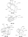
- FIGS. 49-51 illustrate three variations of a chuck assembly 3600 according to another embodiment.
- the chuck assembly 3600 is similar to the chuck assembly 3400 described above with reference to FIG. 47 . Accordingly, the following description focuses primarily on differences between the chuck assembly 3600 and the chuck assembly 3400. In addition, features and elements of the chuck assembly 3600 corresponding with features and elements of the chuck assembly 3400 are given like reference numbers plus 200.
- the collar 3642 includes a skirt 3651 that extends rearward beyond the retaining ring 3646.
- the chuck assembly 3600 includes a sleeve 3604 that can be received inside the skirt 3651 ( FIG. 49 ) or surround the outside of the skirt 3651 ( FIG. 50 ).
- the sleeve 3604 may include an axial recess 3605 that receives and surrounds both the inside and the outside of the skirt 3651. ( FIG. 51 ).
- FIG. 52 illustrates an alternative chuck body 3734 that may be used, for example, with any of the chuck assemblies described herein.
- the chuck body 3734 is similar to the chuck body 3234 described above with reference to FIG. 44 , accordingly, the following description focuses primarily on differences between the chuck body 3734 and the chuck body 3234.
- the shaft portion 3758 of the chuck body 3734 includes a second plurality of slots 3771 and a circumferential flange 3773 disposed between the slots 3762 and the slots 3771.
- the flange 3773 is engageable with a collar (not shown) to limit rearward movement of the collar, and the second slots 3771 are engageable with the collar to limit rotational movement of the collar.
- the collar is coupled for co-rotation with the chuck body 3734 via the slots 3771.
- the illustrated slots 3771 are open at the rear end of the chuck body 3734; however, the slots 3771 may alternatively be closed.
- FIG. 53 illustrates an alternative chuck body 3834 that may be used, for example, with any of the chuck assemblies described herein.
- the chuck body 3834 is similar to the chuck body 3734 described above with reference to FIG. 52 . Accordingly, the following description focuses primarily on differences between the chuck body 3834 and the chuck body 3734.
- the second plurality of slots 3871 extend along the entire length of the chuck body 3834 in the illustrated embodiment, including through the flange 3873.
- the slots 3871 have a V-shape, which may be more economical to manufacture.
- the slots 3871 may extend along only a portion of the length of the chuck body 3834, and the slots 3871 may have other shapes.
- the slots 3871 may be protrusions receivable in corresponding slots in a collar to couple the collar for co-rotation with the chuck body 3834.
- FIG. 54 illustrates a chuck assembly 3900 according to another embodiment.
- the chuck assembly 3900 is similar to the chuck assembly 3600 described above with reference to FIG. 50 . Accordingly, the following description focuses primarily on differences between the chuck assembly 3900 and the chuck assembly 3600. In addition, features and elements of the chuck assembly 3900 corresponding with features and elements of the chuck assembly 3600 are given like reference numbers plus 300.
- the sleeve 3904 of the chuck assembly 3900 accommodates a biasing member 3932, which is a coil spring in the illustrated embodiment.
- the biasing member 3932 may be a wave spring, tapered spring, and the like.
- a snap ring 3933 is coupled to the outside of the skirt 3951, proximate the rear end of the collar 3942. The biasing member 3932 engages the snap ring 3933 to bias the collar 3942 rearward.
- FIG. 55 illustrates an alternative chuck body 4034 that may be used, for example, with any of the chuck assemblies described herein.
- the chuck body 4034 includes a plurality of axially-extending accommodating bores 4053 in the shaft portion 4058.
- a biasing member (not shown), such as a coil spring, is disposed in each of the accommodating bores 4053.
- the biasing members act on a collar (not shown) coupled to the chuck body 4034 to bias the collar rearward. Providing the biasing members within the chuck body 4034 may advantageously reduce the overall size of a chuck assembly that incorporates the chuck body 4034.
- FIG. 56 illustrates a chuck assembly 4100 according to another embodiment.
- the chuck assembly 4100 is similar to the chuck assembly 300 described above with reference to FIGS. 9-13C . Accordingly, the following description focuses primarily on differences between the chuck assembly 4100 and the chuck assembly 300. In addition, features and elements of the chuck assembly 4100 corresponding with features and elements of the chuck assembly 300 are given like reference numbers plus 3800.
- FIG. 57 illustrates one of the jaws 4138 of the chuck assembly 4100.
- the treads 4186 of the steps 4182 are not flat but rather include a plurality of discrete surfaces 4186q, 4186p that intersect along a longitudinal center plane of the jaw 4138.
- each tread 4186 is defined by two discrete surfaces 4186q, 4186p; however, in other embodiments, the treads 4186 may include any other number and arrangement of discrete surfaces.
- chuck assembly 4100 may include jaws 4138' with treads 4186' having a curved shape.
- the treads 4186, 4186' may be concave or convex.
- the risers 4190 of the jaw 4138 in the illustrated embodiment include a corresponding number and arrangement of discrete surfaces 4190q, 4190p; however the risers 4190 may alternatively differ from the treads 4186.
- a collar (not shown) of the chuck assembly 4100 includes steps that match the steps 4182 of the jaws 4138.
- FIG. 59 illustrates an alternative jaw 4238 that may be used, for example, with any of the chuck assemblies described herein.
- the jaw 4238 includes laterally-extending ears 4291 (only one of which is illustrated in FIG. 59 ) between the rear side 4280 and the tip 4274 of the jaw 4238.
- the ears 4291 are generally centered between the rear side 4280 and the tip 4274, but the position of the ears 4291 may vary.
- the ears 4291 may be received in grooves (e.g., the grooves 3167 of the chuck body 3134; FIG. 42 ) to guide radial movement of the jaw 4238.
- the illustrated ear 4291 includes an inclined front surface 4291a.
- the front surface 4291a is inclined in a forward direction to facilitate outward movement of the jaw 4238 (e.g., when the tool bit 14 is pulled forward to be removed).
- a rear surface 4291b of the ear 4291 may also or alternatively be inclined to facilitate outward movement of the jaw 4238 when the tool bit 14 is inserted.
- the ear 4291 may be configured as a slot, with the inclined front surface 4291a being provided on a wall of the slot.
- FIGS. 60A-B illustrates a chuck assembly 6000 according to another embodiment.
- the chuck assembly 6000 is similar to the chuck assembly 300 described above with reference to FIGS. 9-13C . Accordingly, the following description focuses primarily on differences between the chuck assembly 6000 and the chuck assembly 300. In addition, features and elements of the chuck assembly 6000 corresponding with features and elements of the chuck assembly 300 are given like reference numbers plus 5700.
- the steps 6116 are provided on circumferentially spaced fingers 6021 of a collet 6023.
- the collet 6023 is movable relative to the collar 6042 to adjust the position of the steps 6116 relative to the jaws 6038, and thereby adjust a maximum spacing of the jaws 6038 to accommodate differently-sized shanks 18 ( FIG. 2 ).
- the jaws 6038 are biased forward (toward a "closed” position) by a spring 6031.
- a pronged element 6033 is provided between the spring 6031 and the jaws 6038 to facilitate force transfer from the spring 6031 to the jaws 6038. In some embodiments, the pronged element 6033 is axially fixed to the jaws 6038
- the shank 18 of the tool bit 14 is inserted between the jaws 6038, which pushes the jaws 6038 outward to match the nominal size of the shank 18.
- the user rotates the collar 6042.
- the collar 6042 has an internally-threaded portion 6044 that engages with a corresponding threaded portion 6045 (e.g., on the chuck body or on a front end of a power tool).
- a corresponding threaded portion 6045 e.g., on the chuck body or on a front end of a power tool.
- the internally-threaded portion 6044 may be in threaded engagement with the collet 6023.
- the collar 6042 may be rotated to draw the collet 6023 rearward and clamp down on the jaws 6038, while the collar 6042 remains axially fixed.
- the collar 6042 may include an internal spiral wedge (not shown) that produces a clamping force on the jaws 6038 in response to rotation of the collar 6042.
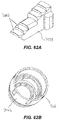
- FIGS. 61A-62B illustrate a chuck assembly 7000 according to another embodiment.
- the chuck assembly 7000 is similar to the chuck assembly 300 described above with reference to FIGS. 9-13C . Accordingly, the following description focuses primarily on differences between the chuck assembly 7000 and the chuck assembly 300.
- features and elements of the chuck assembly 7000 corresponding with features and elements of the chuck assembly 300 are given like reference numbers plus 6700.
- the collar 7042 and jaws 7038 feature curved steps 7082, 7116 that can provide a substantial mechanical advantage and clamping force as the collar 7042 is rotated.
- the curved steps 7116 within the collar 7042 are formed as a series of spiral wedges or cam surfaces ( FIGS. 62A-B ).
- the cam surfaces increase in radial thickness in the tightening direction.
- the steps 7116 may have a tapered shape, which may also provide an increased clamping force.
- the collar 7042 and jaws 7038 can be made to engage at as few as two areas or steps 7082, 7116.
- the collar 7042 When the collar 7042 is rotated to an open position, it can be slid forward and rearward to match a corresponding nominal shank size.
- the collar 7042 is biased rearward and toward a closed position so that the bit shank 18 helps to effectively align the steps 7116 on the collar 7042 with the corresponding steps 7082 on the jaws 7038.
- a spring 7031 biases the collar 7042 rearward.
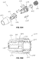
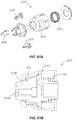
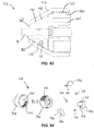
- FIGS. 63 and 64 illustrate a chuck assembly 10d according to another embodiment.
- the chuck assembly 10d is similar to the chuck assembly 10 described above with reference to FIGS. 1-8C . Accordingly, the following description focuses primarily on differences between the chuck assembly 10d and the chuck assembly 10.
- features and elements of the chuck assembly 10d corresponding with features and elements of the chuck assembly 10 are given like reference numbers followed by the letter 'd.'
- the illustrated chuck assembly 10d includes a plurality of springs 13d extending generally in a circumferential direction between adjacent jaws 38d.
- the chuck assembly 10d includes three jaws 38d and thus three springs 13d; however, the chuck assembly 10d may include a greater number of jaws and a correspondingly greater number of springs 13d.
- the springs 13d are received in pockets 15d formed in the lateral faces of each jaw 38d.
- the springs 13d bias the jaws 38d radially outward, such that the oblique outer surface 78d of each jaw 38d is biased into engagement with a frustoconical wedge surface 45d formed on the interior of the collar 42d.
- the jaws 38d may be biased radially outward against the wedge surface 45d in any other suitable manner.
- the jaws 38d may be received within grooves (not shown) in the chuck body 34d to couple the jaws 38d for co-rotation with the chuck body 34d.
- the jaws 38d may be coupled for co-rotation with the chuck body 34d via friction between the jaws 38d and the chuck body 34d or a back stop on the chuck body 34d.
- the collar 42d has internal thread segments 122d that are selectively engageable with corresponding thread segments 70d on the chuck body 34d.
- rotation of the collar 42d in the tightening direction moves the collar 42d rearward, engaging the wedge surface 45d against the oblique outer surfaces 78d of the jaws 38d. This applies a clamping force to a bit shank 18 received between the jaws 38d, thereby securing the bit shank 18.
- FIGS. 65-67 illustrate a chuck assembly 10e according to another embodiment.
- the chuck assembly 10e is similar to the chuck assembly 10d described above with reference to FIGS. 63-64 . Accordingly, the following description focuses primarily on differences between the chuck assembly 10e and the chuck assembly lOd.
- features and elements of the chuck assembly 10e corresponding with features and elements of the chuck assembly 10d are given like reference numbers followed by the letter 'e.'
- each of the jaws 38e is generally shaped as a right trapezoidal prism, with a flat oblique outer surface 78e.
- the wedge surface 45e within the collar 42e is formed with a revolved profile that geometrically corresponds to the oblique outer surfaces 78e of the jaws 38e.
- the revolved profile of the wedge surface 45e may vary in the circumferential direction, so as to converge or diverge from the oblique outer surfaces 78e of the jaws 38e.
- the wedge surface 45e engages the flat oblique outer surfaces 78e only at outer portions of each jaw 38e (with respect to a circumferential direction and as illustrated in FIG.
- the wedge surface 45e is slightly spaced from the outer surface 78e of each jaw along the longitudinal center of each jaw ( FIG. 66 ). This profile of the wedge surface 45e may advantageously increase the stability of the jaws 38e and distribute clamping force evenly over the jaws 38e.
- FIGS. 68-70 illustrate a chuck assembly lOf according to another embodiment.
- the chuck assembly lOf is similar to the chuck assembly 10 described above with reference to FIGS. 1-8C . Accordingly, the following description focuses primarily on differences between the chuck assembly 10f and the chuck assembly 10.
- features and elements of the chuck assembly 10f corresponding with features and elements of the chuck assembly 10 are given like reference numbers followed by the letter 'f.'
- the collar 42f includes a front annular wall 47f that is received in the U-shaped engagement portion 82f of each jaw 38f to couple the jaws 38f for axial movement with the collar 42f.
- the inner periphery of the front annular wall 47f also includes the collar thread segments 122f, which are selectively alignable and engageable with the corresponding thread segments 70f on the chuck body 34f.
- each of the jaws 38f includes an inwardly facing detent 48f that is receivable within the groove 397 of the tool bit shank 18 to axially retain the shank 18 when the shank 18 is received between the jaws 38f.
- the chuck body 34f is configured to be coupled to an output member of a rotary power tool via a chuck screw 49f.
- the illustrated chuck screw 49f includes a head 52f with an inner recess 55f.
- the rear end of a smaller shank 18 (e.g., the first, smaller size 22) is insertable into the inner recess 55f to define a back stop for the smaller shank 18 at a first insertion depth into the chuck assembly 10f ( FIG. 69 ).
- a larger shank 18 (e.g., the second or third nominal size 26, 30) is inserted into the chuck assembly 10f, the rear end of the larger shank 18 engages the head 52f at the outer periphery of the recess 55f, defining a back stop for the larger shank 18 at a second insertion depth that is less (i.e. further forward than) the first insertion depth.
- FIGS. 71-72 illustrate a chuck assembly lOg according to another embodiment.
- the chuck assembly 10g is similar to the chuck assembly 10 described above with reference to FIGS. 1-8C . Accordingly, the following description focuses primarily on differences between the chuck assembly lOg and the chuck assembly 10.
- features and elements of the chuck assembly 10g corresponding with features and elements of the chuck assembly 10 are given like reference numbers followed by the letter 'g.'
- the thread segments 70g on the chuck body 34g and the thread segments 122g inside of the collar 42g have a buttress thread profile.
- the buttress thread profile has the effect of biasing axially loads forward, which may increase the strength of the selective threaded connection between the chuck body 34g and the collar 42g.
- the buttress thread profile allows the thread segments 70g and/or the thread segments 122g to be formed using a bullnose end mill, which can facilitate manufacturing the chuck assembly lOg.
- the chuck assembly lOg further includes a front end cap 56g and a rear end cap 57g fixed to the front and rear sides of the collar 42g.
- the end caps 56g, 57g are press fit to the collar 42g, but the end caps 56g, 57g can be fixed to the collar 42g in other ways (e.g., via fasteners, retaining rings, welding, or the like).
- the front end cap 56g includes an inner lip 59g ( FIG. 72 ) that limits forward travel of the jaws 38g, advantageously eliminating the need for a separate snap ring.
- the rear end cap 57g retains the collar 42g to the chuck body 34g in the rearward direction.
- Each of the jaws 38g of the chuck assembly 10g includes a keyed slot 60g in the oblique outer surface 78g, extending in the longitudinal direction of each jaw 38g.
- the slots 60g received corresponding projections on the front end cap 56g, which helps maintain the circumferential spacing and alignment of the jaws 38g.
- a disc spring 61g is positioned between the inner annular wall 106g of the collar 42g and the first engagement surface 86g of each jaw 38g.
- the disc spring 61g advantageously maintains even pressure on the backs of the jaws 38g and improves user feel when tightening the collar 42g.
- the disc spring 61g may be replaced by a coil spring, wave spring, Belleville washer, or the like.
- the collar 42g is biased forward by a tapered spring 63g, which can minimize axial space requirements while maintaining a high spring rate.
- the threads 70g and/or the threads 122g may be formed with a radially-outward spiral profile.
- the threads 70g and/or the threads 122g may increase in radial height along the tightening direction of the collar 42g.
- the threads 70g, 122g may bottom out to limit rotation of the collar 42g in the tightening direction with the threads 70g, 122g are engaged. Rotation limiting may be achieved using other variably pitched, variably tapered, or other variably profiled threads.
- FIGS. 73-74 illustrate a chuck assembly 10h according to another embodiment.
- the chuck assembly 10h is similar to the chuck assembly 10 described above with reference to FIGS. 1-8C . Accordingly, the following description focuses primarily on differences between the chuck assembly 10h and the chuck assembly 10.
- features and elements of the chuck assembly 10h corresponding with features and elements of the chuck assembly 10 are given like reference numbers followed by the letter 'h.'
- the illustrated chuck assembly 10h has the thread segments 70h located on the head portion 54h of the chuck body 34h, rather than the shaft portion 58h. Positioning the thread segments 70h, 122h on a larger diameter portion of the chuck body 34h may reduce undesirable backdriving, and creates more space at the rear of the chuck body 34h to accommodate the spring 63h, stops, or feedback features, such as ratcheting features.
- the forward location of the thread segments 70h, 122h also places the collar 52h under tension when tightened, rather than compression. This may reduce the required thickness (and therefore mass) of the collar 52h, as compared to collars that are compressed when tightened.
- FIGS. 75-76 illustrate a chuck assembly 10i according to another embodiment.
- the chuck assembly 10i is similar to the chuck assembly 10g described above with reference to FIGS. 71-72 . Accordingly, the following description focuses primarily on differences between the chuck assembly 10i and the chuck assembly lOg.
- features and elements of the chuck assembly 10i corresponding with features and elements of the chuck assembly lOg are given like reference numbers followed by the letter 'i.'
- the chuck assembly 10i includes a pusher ring 71i disposed between the spring 63i and the inner annular wall 106i of the collar 42i.
- the pusher ring 71i may be made of plastic in some embodiments.
- the pusher ring 71i transfers the biasing force of the spring 63i to the collar 42i while keeping the spring 63i from interfering with the jaws 38i.
- the disc spring 61i in the illustrated embodiment is keyed to the chuck body 34i for co-rotation with the chuck body 34i.
- the front end cap 56i is also keyed to the front of the chuck body 34i.
- a detent mechanism or ratcheting mechanism may be provided between the collar 42i and the chuck body 34i to provide a desired feel when tightening or loosening the collar 42i.
- FIGS. 77-78B illustrate a chuck assembly lOj according to another embodiment.
- the chuck assembly lOj is similar to the chuck assembly 10 described above with reference to FIGS. 1-8C . Accordingly, the following description focuses primarily on differences between the chuck assembly 10j and the chuck assembly 10.
- features and elements of the chuck assembly 10j corresponding with features and elements of the chuck assembly 10 are given like reference numbers followed by the letter 'j.'
- Each of the jaws 38j of the chuck assembly lOj has a plurality of oblique outer surfaces 78j such that the jaws 38j have a non-circular outer profile.
- the outer surfaces 78j of the jaws 38j collectively define a hexagonal outer profile.
- the non-circular outer profile of the jaws 38j may render the jaws 38j easier to manufacture, align, and retain at a desired position.
- the chuck assembly 10j further includes a wave spring 61j ( FIG. 78B ) disposed between the inner annular wall 106j of the collar 42j and the first engagement surface 86j of each jaw 38j.
- the illustrated wave spring 61j has a plurality of integral axially-extending detents 73j (e.g., dimples or ridges) on a front side of the wave spring 61j that are received within rearward-facing vertical slots 91j in each jaw 38j.
- the wave spring 61j is coupled for co-rotation with the jaws 38j.
- the wave spring 61j may be a disc spring keyed to the chuck body 34j, such as the disc spring 61i described above with reference to FIGS. 75-76 .
- a rear side of the illustrated wave spring 61j includes a plurality of axially extending detents 93j ( FIG. 78B ) that are engageable with corresponding indentations 95j ( FIG. 78A ) on the front side of the inner annular wall 106j of the collar 42j.
- the engagement between the detents 93j and the indentations 95j may provide tactile and/or audible feedback (e.g., a ratcheting sound and sensation) to the user upon rotating the collar 42j.
- the detents 93j and indentations 95j may be reversed, such that the wave spring 61j includes the indentations 95j and the collar 42j includes the detents 93j.
- the wave spring 61j and the collar 42j may include other types of inter-engaging features.
- the front end cap 56j of the chuck assembly 10j includes slots 99j that receive respective resilient elements 101j (e.g., leaf springs).
- the resilient elements 101j are engageable with inner ridges 76j formed within the collar 42j to provide additional tactile feedback (e.g., a ratcheting sound and sensation) to the user upon rotating the collar 42j.
- the front end cap 56j may be omitted and the resilient elements 101j may be directly coupled to the chuck body 34j and engageable with the inner ridges 76j in the collar 42j to provide tactile and/or audible feedback.
- the illustrated chuck assembly 10j includes a plurality of springs 75j spaced around the outer periphery of the chuck body 34j.
- each of the springs 75j is disposed in a slot or bore 77j extending longitudinally along the chuck body 34j.
- the springs 75j are engageable with the collar 42j to bias the collar 42j rearward in some embodiments, or forward in other embodiments.
- a central coil spring for biasing the collar 42j can be omitted, freeing up internal space within the chuck assembly 10j and allowing for a more compact overall assembly.
- the chuck assembly 10j may include more than three springs 75j.
- FIG. 79 illustrates a chuck assembly 10k according to another embodiment.
- the chuck assembly 10k is similar to the chuck assembly 10 described above with reference to FIGS. 1-8C . Accordingly, the following description focuses primarily on differences between the chuck assembly 10k and the chuck assembly 10.
- features and elements of the chuck assembly 10k corresponding with features and elements of the chuck assembly 10 are given like reference numbers followed by the letter 'k.'
- the chuck assembly 10k includes a thread carrier 81k keyed for co-rotation with the chuck body 34k (e.g., via a spline fit, a plurality of pins, or the like), but axially movable along the chuck body 34k during assembly.
- a thread positioning member 83k, with an internally threaded bore 85k, is threaded onto the shaft portion 58k of the chuck body 34k.
- the thread carrier 81k includes the thread segments 70k that are engageable with the corresponding thread segments 122k on the collar 42k.
- the thread positioning member 83k is rotatable to advance forward or backward along the shaft portion 58k to set a final position of the thread carrier 81k.
- the thread positioning member 83k and/or the thread carrier 81k can be locked in place after assembly and adjustment (e.g., via a thread-locking adhesive, thread interference, or any other suitable means).
- FIG. 80 illustrates a chuck assembly 101 according to another embodiment.
- the chuck assembly 101 is similar to the chuck assembly 10k described above with reference to FIG. 79 . Accordingly, the following description focuses primarily on differences between the chuck assembly 101 and the chuck assembly 10k In addition, features and elements of the chuck assembly 101 corresponding with features and elements of the chuck assembly 10k are given like reference numbers followed by the letter 'l.'
- the internally threaded bore 851 is provided in the thread carrier 811, such that the thread positioning member 83k described above can be omitted. That is, the thread carrier 811 is threaded on to the shaft portion 581 of the chuck body 341, and can be adjusted along the chuck body 341 and secured in a final axial position during assembly.
- FIG. 81 illustrates a chuck assembly 10m according to another embodiment.
- the chuck assembly 10m is similar to the chuck assembly 10 described above with reference to FIGS. 1-8C . Accordingly, the following description focuses primarily on differences between the chuck assembly 10m and the chuck assembly 10.
- features and elements of the chuck assembly 10m corresponding with features and elements of the chuck assembly 10 are given like reference numbers followed by the letter 'm.'
- the chuck assembly 10m includes sleeve insert 91m disposed within and movable with the collar 42m.
- the helical thread segments 122m are provided on the insert 91m, which may reduce tolerance requirements and associated costs of manufacturing the collar 42m.
- FIGS. 82-83 illustrate a chuck assembly 10n according to another embodiment.
- the chuck assembly 10n is similar to the chuck assembly 10 described above with reference to FIGS. 1-8C . Accordingly, the following description focuses primarily on differences between the chuck assembly 10n and the chuck assembly 10.
- features and elements of the chuck assembly 10n corresponding with features and elements of the chuck assembly 10 are given like reference numbers followed by the letter 'n.'
- the thread segments 70n are provided on the oblique outer surfaces 78n of the jaws 38n (rather than on the chuck body 34n).
- the thread segments 70n may be machined into the jaws 38n, or may be integrally formed with the jaws 38n (e.g., in a molding process, a powdered metal compacting and sintering process, or the like).
- the U-shaped engagement portion 82n of the jaws 38n that receives a rear wall 97n of the collar 42n is disposed behind the thread segments 70n.
- the U-shaped engagement portion 82n may be disposed in front of the thread segments 70n (to receive, for example, a front wall of the collar 42n).
- FIG. 84 illustrates a back stop 210 for use with a chuck assembly that includes a plurality of jaws 211 and a chuck screw 212 that couples a body of the chuck assembly (not shown) to an output of a rotary power tool.
- the back stop 210 may be incorporated into any of the chuck assemblies described herein.
- a chuck assembly that includes a plurality of jaws 211 and a chuck screw 212 that couples a body of the chuck assembly (not shown) to an output of a rotary power tool.
- the back stop 210 may be incorporated into any of the chuck assemblies described herein.
- a chuck assembly if the bit shank 18 bottoms out on the chuck screw 212, it can cause the jaws 211 to jam, making it very difficult to remove the bit shank 18 from the chuck assembly. This problem may be exacerbated on rotary power tools configured to apply axial impacts to the bit shank 18 (e.g., hammer drills and rotary hammers).
- the illustrated back stop 210 includes an elastomeric plug 214 coupled to a head 218 of the chuck screw 212.
- the elastomeric plug 214 is engageable with a rear end of a bit shank 18 inserted between the jaws 211 to prevent the rear end of the bit shank 18 from bottoming out on the chuck screw 212.
- the chuck screw 212 may be configured as a security screw with a projection extending beyond the head 218 in place of the elastomeric plug 214.
- the elastomeric plug 214 may simply be fixed to a back wall of the chuck assembly.
- FIG. 85 illustrates a back stop 222 according to another embodiment.
- the illustrated back stop 222 includes a ledge 226 formed on at least one of the jaws 211.
- the ledge 226 is engageable with a rear end of a bit shank 18 inserted between the jaws 211 to prevent the rear end of the bit shank 18 from bottoming out on the chuck screw 212 (or the back of the chuck assembly).
- FIG. 86 illustrates a varying helical thread 250 that may be incorporated into a chuck assembly, such as any of the chuck assemblies described and illustrated herein.
- the helical thread 250 includes a transition point 254 at which the thread pitch changes from a first pitch to a second pitch different than the first pitch.
- the varying helical thread 250 may be used to provide a greater mechanical advantage within particular rotational regions (e.g., of a sleeve relative to a chuck body).
- the varying helical thread 250 may also define rotational stop positions.
Landscapes
- Engineering & Computer Science (AREA)
- Mechanical Engineering (AREA)
- Gripping On Spindles (AREA)
Abstract
Description
- This application claims priority to co-pending
U.S. Provisional Application No. 62/632,000, filed February 19, 2018 U.S. Provisional Application No. 62/573,849, filed October 18, 2017 - The present invention relates to power tools, and more particularly to chuck assemblies for rotary power tools.
- Power tools having a rotational output (i.e. rotary power tools) typically include chuck assemblies with a plurality of jaws that are adjustable to grip and secure a tool bit (e.g., a drill bit). Some chuck assemblies are configured to accept a continuous range of bit sizes (referred to herein as "continuously variable chucks"). Other chuck assemblies are configured to accept one standard size of hex-shanked bits. By taking advantage of a standard shank geometry, such chuck assemblies can be optimized to reduce weight, size, manufacturing cost, and time required to change bits as compared to continuously variable chucks. However, multiple standard nominal sizes exist for hex-shanked bits. For example, 1/4-inch hex bits are commonly used for fastener driver, drill, and accessory bits, 3/8-inch hex bits are commonly used for hole saw bits, and 7/16-inch hex bits may be used for higher torque applications. The actual outer width dimension of such hex bits may be slightly different than the nominal size. For example, nominal 3/8-inch hex bits may have an actual out width dimension of 11/32-inch.
- A need exists for a chuck able to accept multiple standard sized bit shanks without suffering the disadvantages of continuously variable chucks.
- The invention provides, in a first aspect, a chuck assembly for a rotary power tool. The chuck assembly includes a chuck body rotatable about a central axis. The chuck body has a plurality of slots, each oriented at an oblique angle relative to the central axis. The chuck assembly also includes a plurality of jaws, each movable along a respective one of the slots. The chuck assembly also includes a collar coupled to the plurality of jaws. The collar is selectively engageable with the chuck body such that, when engaged, the plurality of jaws is movable along the plurality of slots in response to rotation of the collar.
- The collar may be movable relative to the chuck body along the central axis, without rotating the collar, when the collar is disengaged from the chuck body. The jaws may be movable along the slots in response to movement of the collar along the central axis.
- The chuck body may include a first plurality of thread segments. The collar may include a second plurality of thread segments. The collar may be rotatable relative to the chuck body to selectively engage at least one of the first plurality of thread segments with at least one of the second plurality of thread segments.
- The chuck assembly may further comprise a ring coupled to the collar for axial movement with the collar relative to the chuck body. The ring may be coupled to the chuck body for co-rotation with the chuck body. The collar may be rotatable relative to the ring. One of the ring or the collar may include an axially-extending detent. The other of the ring or the collar may include an arcuate groove in which the detent may be received. The groove may include texture that provides tactile or audible feedback when the collar is rotated relative to the ring.
- The invention provides, in a second aspect, a chuck assembly for coupling a bit shank to a rotary power tool. The chuck assembly includes a chuck body rotatable about a central axis, and having a plurality of slots. The chuck assembly also includes a plurality of jaws, each of the jaws movable along a respective one of the slots to secure a bit shank between the jaws, and a collar at least partially surrounding the chuck body and the jaws. A first plurality of threads is formed on the chuck body or the plurality of jaws, and a second plurality of threads is formed on the collar. The collar is rotatable about the central axis to a first orientation to engage the second plurality of threads with the first plurality of threads and to a second orientation to disengage the second plurality of threads from the first plurality of threads. The collar is axially movable along the chuck body without rotating the collar when the collar is in the second orientation.
- The the jaws may be coupled for movement with the collar along the central axis. The jaws may be movable along the slots in response to movement of the collar along the central axis.
- The chuck assembly of the second aspect of the invention may further comprise a chuck screw configured to couple the chuck body to the rotary power tool. The chuck screw may include a head; and a back stop configured to prevent a back end of the bit shank from contacting the head of the chuck screw. The back stop may include an elastomeric plug.
- The invention provides, in a third aspect, a method of securing a bit shank with a chuck assembly. The method includes retracting a plurality of jaws by sliding a collar along a chuck body in a first direction, inserting the bit shank between the jaws, engaging the jaws against first bit shank by sliding the collar along the chuck body in a second direction opposite the first direction, rotating the collar relative to the chuck body, and by rotating the collar, applying a clamping force to the first bit shank with the jaws.
- Rotating the collar may include engaging a plurality of thread segments on the collar with a plurality of thread segments on the chuck body.
- Rotating the collar may include engaging a plurality of thread segments on the collar with a plurality of thread segments on each of the plurality of jaws.
- Retracting the plurality of jaws may include engaging each of the plurality of jaws with a ring coupled between the collar and the jaws.
- Inserting the bit shank between the jaws may include engaging a rear end of the bit shank against a back stop.
- The back stop may be integrally formed with at least one of the plurality of jaws.
- The invention provides, in a fourth aspect, a chuck assembly for a rotary power tool. The chuck assembly includes a chuck body rotatable about a central axis and having a plurality of slots oriented perpendicular to the central axis. The chuck assembly also includes a plurality of jaws, each movable along a respective one of the slots, and each having a stepped outer side. The chuck assembly also includes a collar coupled for sliding movement along the chuck body. The collar has a plurality of steps engageable with the stepped outer side of each of the jaws. In a first position of the collar in which a first plurality of the steps is engageable with the stepped outer side of each of the jaws, the chuck assembly is configured to secure a bit shank of a first nominal size, and in a second position of the collar in which a second plurality of the steps is engageable with the stepped outer side of each of the jaws, the chuck assembly is configured to secure a bit shank of a second nominal size different than the first nominal size.
- The collar may be movable to a third position in which a third of the plurality of steps is engageable with the stepped outer side of each of the jaws to secure a bit shank of a third nominal size different than the second nominal size and the first nominal size.
- The chuck assembly of the fourth aspect of the invention may further comprise a spring configured to bias the collar into engagement with the plurality of jaws.
- At least one of the plurality of jaws may include a detent. The detent may be engageable with a groove in the bit shank of the first nominal size or a groove in the bit shank of the second nominal size to axially secure the bit shank between the jaws.
- The invention provides, in fifth aspect, a chuck assembly for a rotary power tool. The chuck assembly includes a chuck body rotatable about a central axis, the chuck body including a plurality of slots, and a plurality of jaws. Each of the jaws is movable along a respective one of the slots to axially and radially secure bit shanks of only a plurality of discrete nominal sizes between the jaws.
- The chuck assembly of the fifth aspect of the invention may further comprise a collar coupled to the chuck body. The collar may be slidable along the chuck body. The collar may be rotatable relative to the chuck body. The collar may be rotatable relative to the chuck body to apply a clamping force to a bit shank via the jaws to axially and radially secure the bit shank between the jaws.
- At least one of the jaws may include a detent projecting from the at least one jaw. The detent may be engageable with a groove in a bit shank to axially secure the bit shank between the jaws.
- Other features and aspects of the invention will become apparent by consideration of the following detailed description and accompanying drawings.
-
-
FIG. 1 is a perspective view of a chuck assembly according to an embodiment of the invention. -
FIG. 2 is a perspective view of an exemplary tool bit that can be retained by the chuck assembly ofFIG. 1 . -
FIG. 3 is a diagram illustrating three different nominal sizes of shanks that may be used on the tool bit ofFIG. 2 . -
FIG. 4 is an exploded view of the chuck assembly ofFIG. 1 . -
FIG. 5 is another exploded view of the chuck assembly ofFIG. 1 . -
FIG. 6 is a cross-sectional view of the chuck assembly ofFIG. 1 . -
FIG. 7 is a cross-sectional view of the chuck assembly ofFIG. 1 with a collar of the chuck assembly in a rearmost position. -
FIG. 8A illustrates the chuck assembly ofFIG. 1 configured to clamp a shank of a first nominal size. -
FIG. 8B illustrates the chuck assembly ofFIG. 1 configured to clamp a shank of a second nominal size. -
FIG. 8C illustrates the chuck assembly ofFIG. 1 configured to clamp a shank of a third nominal size. -
FIG. 9 is a perspective view of a chuck assembly according to another embodiment of the invention. -
FIG. 10 is an exploded view of the chuck assembly ofFIG. 9 . -
FIG. 11 is another exploded view of the chuck assembly ofFIG. 9 . -
FIG. 12 is a cross-sectional view of the chuck assembly ofFIG. 9 with a collar of the chuck assembly in a forward-most position. -
FIG. 13A illustrates the chuck assembly ofFIG. 9 configured to secure a shank of a first nominal size. -
FIG. 13B illustrates the chuck assembly ofFIG. 9 configured to secure a shank of a second nominal size. -
FIG. 13C illustrates the chuck assembly ofFIG. 9 configured to secure a shank of a third nominal size. -
FIG. 14 illustrates a jaw according to another embodiment for use with the chuck assembly ofFIG. 9 . -
FIG. 15 is a cross-sectional view of a portion of a chuck assembly according to another embodiment of the invention. -
FIG. 16A illustrates the chuck assembly ofFIG. 15 configured to secure a shank of the first nominal size. -
FIG. 16B illustrates the chuck assembly ofFIG. 15 configured to secure a shank of the second nominal size. -
FIG. 16C illustrates the chuck assembly ofFIG. 15 configured to secure a shank of the third nominal size. -
FIG. 17 is a perspective view of a chuck assembly according to another embodiment of the invention. -
FIG. 18 is a cross-sectional view of the chuck assembly ofFIG. 17 . -
FIG. 19 is a cross-sectional view of a portion of a chuck assembly according to another embodiment of the invention. -
FIG. 20 is a cross-sectional view of a portion of a chuck assembly according to another embodiment of the invention. -
FIG. 21 is a perspective view of a jaw according to one embodiment, for use with a chuck assembly. -
FIG. 22 is a perspective view of a jaw according to another embodiment, for use with a chuck assembly. -
FIG. 23 is a cross-sectional view of a portion of a chuck assembly according to another embodiment of the invention. -
FIG. 24 is a cross-sectional view of a portion of a chuck assembly according to another embodiment of the invention. -
FIG. 25A is a front view of a jaw according to another embodiment, for use with a chuck assembly. -
FIG. 25B is a side view of the jaw ofFIG. 25A . -
FIG. 25C is a perspective view of the jaw ofFIG. 25A . -
FIG. 26A is a front view of a jaw according to another embodiment, for use with a chuck assembly. -
FIG. 26B is a side view of the jaw ofFIG. 26A . -
FIG. 26C is a perspective view of the jaw ofFIG. 26A . -
FIG. 27A is a front view of a jaw according to another embodiment, for use with a chuck assembly. -
FIG. 27B is a cross-sectional view of the jaw ofFIG. 27A . -
FIG. 27C is a perspective view of the jaw ofFIG. 27A . -
FIG. 28 is a cross-sectional view of a jaw according to another embodiment, for use with a chuck assembly. -
FIG. 29 is a cross-sectional view of a jaw according to another embodiment, for use with a chuck assembly. -
FIG. 30 is a cross-sectional view of a jaw according to another embodiment, for use with a chuck assembly. -
FIG. 31A is a front view of a jaw according to another embodiment, for use with a chuck assembly. -
FIG. 31B is a cross-sectional view of the jaw ofFIG. 31A . -
FIG. 31C is a perspective view of the jaw ofFIG. 31A . -
FIG. 32 is a cross-sectional view of a portion of a chuck assembly according to another embodiment of the invention. -
FIG. 33 is a cross-sectional view of a portion of a chuck assembly according to another embodiment of the invention. -
FIG. 34 is a cross-sectional view of a portion of a chuck assembly according to another embodiment of the invention. -
FIG. 35 is a cross-sectional view of a portion of a chuck assembly according to another embodiment of the invention. -
FIG. 36 is a cross-sectional view of a jaw according to another embodiment, for use with a chuck assembly. -
FIG. 37 is a cross-sectional view of a jaw according to another embodiment, for use with a chuck assembly. -
FIG. 38 is a perspective view of a jaw according to another embodiment, for use with a chuck assembly. -
FIG. 39 is a top view of the jaw ofFIG. 38 incorporated into the chuck assembly. -
FIG. 40A is a cross-sectional view of a chuck assembly according to another embodiment of the invention, securing a shank of a first nominal size. -
FIG. 40B is a cross-sectional view of the chuck assembly ofFIG. 40A , securing a shank of a second nominal size. -
FIG. 40C is a cross-sectional view of the chuck assembly ofFIG. 40A , securing a shank of a third nominal size. -
FIG. 41 is a perspective view of a chuck body according to one embodiment, for use with a chuck assembly. -
FIG. 42 is a perspective view of a chuck body according to another embodiment, for use with a chuck assembly. -
FIG. 43 is a perspective view of a jaw according to another embodiment, for use with a chuck assembly. -
FIG. 44 is a perspective view of a chuck body according to another embodiment, for use with a chuck assembly. -
FIG. 45 is a cross-sectional view of a collar according to one embodiment, for use with a chuck assembly. -
FIG. 46 is a cross-sectional view of a collar according to another embodiment, for use with a chuck assembly. -
FIG. 47 is a cross-sectional view of a chuck assembly according to another embodiment of the invention. -
FIG. 48 is a cross-sectional view of a chuck assembly according to another embodiment of the invention. -
FIG. 49 is a cross-sectional view of a chuck assembly according to another embodiment of the invention. -
FIG. 50 is a cross-sectional view of a chuck assembly according to another embodiment of the invention. -
FIG. 51 is a cross-sectional view of a chuck assembly according to another embodiment of the invention. -
FIG. 52 is a perspective view of a chuck body according to another embodiment, for use with a chuck assembly. -
FIG. 53 is a perspective view of a chuck body according to another embodiment, for use with a chuck assembly. -
FIG. 54 is a cross-sectional view of a chuck assembly according to another embodiment of the invention. -
FIG. 55 is a perspective view of a portion of a chuck assembly according to another embodiment of the invention. -
FIG. 56 is a cross-sectional view of a portion of a chuck assembly according to another embodiment of the invention. -
FIG. 57 is a perspective view of a jaw of the chuck assembly ofFIG. 56 . -
FIG. 58 is a cross-sectional view of the portion of the chuck assembly ofFIG. 56 , including a jaw according to another embodiment. -
FIG. 59 is a side view of a jaw according to another embodiment, for use with a chuck assembly. -
FIG. 60A is an exploded perspective view of a chuck assembly according to another embodiment of the invention. -
FIG. 60B is a cross-sectional view of the chuck assembly ofFIG. 60A . -
FIG. 61A is an exploded perspective view of a chuck assembly according to another embodiment of the invention. -
FIG. 61B is a cross-sectional view of the chuck assembly ofFIG. 61A -
FIG. 62A is a perspective view of a jaw of the chuck assembly ofFIG. 61A -
FIG. 62B is a rear perspective view of a collar of the chuck assembly ofFIG. 61A -
FIG. 63 is a cross-sectional view of a chuck assembly according to another embodiment of the invention. -
FIG. 64 is an exploded perspective view of the chuck assembly ofFIG. 63 . -
FIG. 65 is a front view of the chuck assembly according to another embodiment. -
FIG. 66 is a cross-sectional view of the chuck assembly ofFIG. 65 , taken along line 66-66 inFIG. 65 . -
FIG. 67 is a cross-sectional view of the chuck assembly ofFIG. 65 , taken along line 67-67 inFIG. 65 . -
FIG. 68 is an exploded perspective view of a chuck assembly according to another embodiment of the invention. -
FIG. 69 is a cross-sectional view of the chuck assembly ofFIG. 68 , securing a shank of a first nominal size. -
FIG. 70 is a cross-sectional view of the chuck assembly ofFIG. 68 , securing a shank of a second nominal size. -
FIG. 71 is an exploded perspective view of a chuck assembly according to another embodiment of the invention. -
FIG. 72 is a cross-sectional view of the chuck assembly ofFIG. 71 . -
FIG. 73 is an exploded perspective view of a chuck assembly according to another embodiment of the invention. -
FIG. 74 is a cross-sectional view of the chuck assembly ofFIG. 73 . -
FIG. 75 is an exploded perspective view of a chuck assembly according to another embodiment of the invention. -
FIG. 76 is a cross-sectional view of the chuck assembly ofFIG. 75 . -
FIG. 77 is an exploded perspective view of a chuck assembly according to another embodiment of the invention. -
FIG. 78A is a cross-sectional view of the chuck assembly ofFIG. 77 . -
FIG. 78B is a perspective view of a wave spring of the chuck assembly ofFIG. 77 . -
FIG. 79 is an exploded perspective view of a chuck assembly according to another embodiment of the invention. -
FIG. 80 is an exploded perspective view of a chuck assembly according to another embodiment of the invention. -
FIG. 81 is an exploded perspective view of a chuck assembly according to another embodiment of the invention. -
FIG. 82 is an exploded perspective view of a chuck assembly according to another embodiment of the invention. -
FIG. 83 is a cross-sectional view of the chuck assembly ofFIG. 82 . -
FIG. 84 illustrates a back stop for a chuck assembly according to an embodiment of the invention. -
FIG. 85 illustrates a back stop for a chuck assembly according to another embodiment of the invention. -
FIG. 86 illustrates a varying helical thread that may be incorporated into any of the chuck assemblies described and illustrated herein. - Before any embodiments of the invention are explained in detail, it is to be understood that the invention is not limited in its application to the details of construction and the arrangement of components set forth in the following description or illustrated in the following drawings. The invention is capable of other embodiments and of being practiced or of being carried out in various ways. Also, it is to be understood that the phraseology and terminology used herein is for the purpose of description and should not be regarded as limiting.
-
FIG. 1 illustrates achuck assembly 10 for connection to an output member (e.g., a spindle; not shown) of a rotary power tool (e.g., a drill, impact driver, etc.; not shown). Thechuck assembly 10 is configured to quickly receive and secure tool bits with standardized shanks of at least two different predetermined, nominal sizes. For example, the illustratedchuck assembly 10 is configured to receive atool bit 14 with ahexagonal shank 18 that can be any one of a firstnominal size 22, a secondnominal size 26, and a third nominal size 30 (FIGS. 2 and3 ). The first, second, and thirdnominal sizes chuck assembly 10 may be configured to receive tool bits with other types of shanks (e.g., square, three-flat, round, etc.). In addition, thechuck assembly 10 may be configured to receive tool bits of four or more different nominal shank sizes. - With reference to
FIGS. 4 and5 , thechuck assembly 10 includes achuck body 34, a plurality ofjaws 38, acollar 42, and asplit ring 46. Thechuck body 34 is coupled for co-rotation with the output member of the power tool about acentral axis 50. Thechuck body 34 includes ahead portion 54, ashaft portion 58, and a plurality ofslots 62 in which therespective jaws 38 are slidably received. Each of theslots 62 is oriented at an oblique angle relative to thecentral axis 50. Theshaft portion 58 includes a plurality of externally-threadedsections 66 disposed circumferentially about theshaft portion 58 between the slots 62 (FIG. 5 ). Each threadedsection 66 includes a plurality ofhelical thread segments 70 situated adjacent one another along theaxis 50. The illustratedthread segments 70 project outwardly from theshaft portion 58; however, in other embodiments, thethread segments 70 may be defined by slots cut into theshaft portion 58. As described in greater detail below, the number ofthread segments 70 is at least equal to the predetermined number of tool bit shank sizes that thechuck assembly 10 is adapted to receive. Accordingly, in the illustrated embodiment, each threadedsection 66 includes three thread segments 70: afirst thread segment 70a, asecond thread segment 70b, and athird thread segment 70c (FIGS. 8A-8C ). In other embodiments,additional thread segments 70 may be provided. In addition, the relative axial position of each of thethread segments chuck assembly 10. - With continued reference to
FIGS. 4 and5 , the illustratedchuck assembly 10 includes threejaws 38; however, thechuck assembly 10 may include any number ofjaws 38. Each of thejaws 38 has a front portion ortip 74 and an obliqueouter surface 78 extending rearward from thetip 74. Each of thejaws 38 may include a generallyU-shaped engagement portion 82 at the rear end of thejaw 38 opposite thetip 74. Theengagement portion 82 includes opposing first and second engagement surfaces 86, 90 that define agroove 94 therebetween. Abase surface 98 extending between the first and second engagement surfaces 86, 90 forms the bottom of thegroove 94. In the illustrated embodiment, the first and second engagement surfaces 86, 90 extend perpendicular to thecentral axis 50, and thebase surface 98 extends parallel to thecentral axis 50. - The
collar 42 is received on theshaft portion 58 of thechuck body 34 and is rotatable and axially movable relative to thechuck body 34. The illustratedcollar 42 includes a user-manipulableouter surface 102 and an innerannular wall 106. Theannular wall 106 includes a front side 110 (FIG. 5 ), a back side 114 (FIG. 4 ), and an interior side 118 that extends between thefront side 110 and theback side 114. The illustratedcollar 42 includes askirt portion 51 extending rearward from the annular wall 106 (FIGS. 6 and 7 ). The interior of theskirt portion 51 defines arecess 53 that may receive an annular projecting portion (not shown) formed, for example, as a part of thechuck body 34 or as a part of a front end assembly of a power tool. - Best illustrated in
FIGS. 6 and 7 , theannular wall 106 extends into thegroove 94 of eachjaw 38 such that thefront side 110 of theannular wall 106 opposes thefirst engagement surface 86. Accordingly, when thecollar 42 is moved forward (i.e. to the left inFIGS. 6 and 7 ) relative to thechuck body 34, thefront side 110 of theannular wall 106 bears against thefirst engagement surface 86 to move thejaws 38 forward. As thejaws 38 move forward, they also move radially inward due to the oblique orientation of theslots 62. Forward movement of thecollar 42 is limited by engagement between thefront side 110 of theannular wall 106 and thehead portion 54 of the chuck body 34 (FIG. 6 ). Thecollar 42 further includes a plurality of inwardly-projectinghelical thread segments 122 provided on the interior side 118 of theannular wall 106. In the illustrated embodiment, the thread segments 112 project from the interior side 118; however, in other embodiments, the thread segments 112 may be defined by slots cut into the interior side 118. As described in greater detail below, thethread segments 122 on thecollar 42 are selectively engageable with thethread segments 70 on thechuck body 34, and thecollar 42 is rotatable relative to thechuck body 34 to clamp theshank 18 of thetool bit 14 between thejaws 38. - Referring to
FIGS. 4 and5 , thesplit ring 46 is received on theshaft portion 58 of thechuck body 34 adjacent theback side 114 of the collar'sannular wall 106. Thesplit ring 46 is axially movable with thecollar 42 relative to thechuck body 34. Thesplit ring 46 includes afront side 126, aback side 130, a plurality of inwardly-projecting, circumferentially spaced retainingtabs 134 and a plurality ofguide tabs 138 that extend from theback side 130. Thesplit ring 46 further includes agap 142 that allows for resilient expansion of the split ring 46 (e.g., during assembly of the chuck assembly 10). Best illustrated inFIGS. 6 and 7 , thefront side 126 of thesplit ring 46 opposes theback side 114 of the collar'sannular wall 106. Accordingly, when thecollar 42 is moved rearward (i.e. to the right inFIGS. 6 and 7 ) relative to thechuck body 34, theback side 114 of theannular wall 106 bears against thefront side 126 of thesplit ring 46 to move thesplit ring 46 rearward with thecollar 42. The retainingtab 134 bears against thesecond engagement surface 90 to also move thejaws 38 rearward. As thejaws 38 move rearward, they move radially-outward due to the oblique orientation of theslots 62. Rearward movement of thecollar 42 and thesplit ring 46 is limited by engagement of thebase surface 98 with the retaining tabs 134 (FIG. 7 ). Rearward movement of thecollar 42 and thesplit ring 46 may also be limited by engagement between thecollar 42 and a portion of the power tool (e.g., the power tool housing; not shown). Theguide tabs 138 are configured to overlie and engage the threadedsections 66 of thechuck body 34 to maintain thesplit ring 46 in alignment with thecentral axis 50. - The
front side 126 of thesplit ring 46 optionally includes a pair of axially-extending nubs or detents 146 (FIG. 5 ). Thedetents 146 are received in respectivearcuate grooves 150 formed in theback side 114 of the annular wall 106 (FIG. 4 ). Accordingly, relative rotation between thecollar 42 and thesplit ring 46 is limited by one or both of thedetents 146 engaging an end of the correspondingarcuate groove 150. In the illustrated embodiment, thearcuate grooves 150 are provided with a ridged or knurled texture, which may provide tactile and/or audible feedback when thecollar 42 is rotated relative to thesplit ring 46. The texture may also increase friction between thedetents 146 and thegrooves 150 to provide thecollar 42 with a desired level of rotational resistance. In other embodiments, thegrooves 150 may be generally smooth. - In operation, to clamp a
tool bit 14 of the firstnominal shank size 22, a user rotates the collar 42 (e.g., by about 60 degrees in the illustrated embodiment) to disengage thethread segments 122 on thecollar 42 from thethread segments 70 on thechuck body 34. This occurs when thethread segments 122 are aligned with theslots 62, rather than with thethread segments 70. With thethread segments collar 42, splitring 46, andjaws 38 are freely axially movable along thechuck body 34. Next, the user pushes thecollar 42 back toward its rearmost position (FIG. 7 ), corresponding with the open-most position of thejaws 38. The user positions theshank 18 of thetool bit 14 between thejaws 38, and then moves thecollar 42 forward until thejaws 38 come into contact with theshank 18. In some embodiments, thecollar 42 may be biased forward by a spring (not shown; the spring may act, for example, on theback side 130 of the split ring 46). Next, the user begins to rotate thecollar 42 in a tightening direction. Because the axial position of thefirst thread segments 70a corresponds with the firstnominal shank size 22, thecollar thread segments 122 engage the front of thefirst thread segments 70a (FIG. 8A ). The engagement of thethread segments collar 42 forward, which in turn pushes thejaws 38 forward and inward to exert a clamping force on theshank 18, thereby securing thetool bit 14 in thechuck assembly 10. - To replace the
tool bit 14 with atool bit 14 of the secondnominal shank size 26, the user rotates thecollar 42 in a loosening direction opposite the tightening direction to disengage thethread segments 122 on thecollar 42 from thethread segments 70 on thechuck body 34. Rotating thecollar 42 in the loosening direction also releases the clamping force and permits removal of the existingtool bit 14. With thethread segments collar 42, splitring 46, andjaws 38 are freely axially movable along thechuck body 34. The user pushes thecollar 42 back toward its rearmost position (FIG. 7 ), corresponding with the open-most position of thejaws 38. The user positions theshank 18 of the secondnominal size 26 between thejaws 38, and then moves thecollar 42 forward until thejaws 38 come into contact with theshank 18. Next, the user begins to rotate thecollar 42 in the tightening direction. Because the axial position of thesecond thread segments 70b corresponds with the secondnominal shank size 26, thecollar thread segments 122 engage the front of thesecond thread segments 70b (FIG. 8B ). The engagement of thethread segments collar 42 forward, which in turn pushes thejaws 38 forward and inward to exert a clamping force on theshank 18, thereby securing thetool bit 14 in thechuck assembly 10. - Likewise, to replace the
tool bit 14 with atool bit 14 of the thirdnominal shank size 30, the user rotates thecollar 42 in the loosening direction opposite to disengage thethread segments 122 on thecollar 42 from thethread segments 70 on thechuck body 34. Rotating thecollar 42 in the loosening direction also releases the clamping force and permits removal of the existingtool bit 14. With thethread segments collar 42, splitring 46, andjaws 38 are freely axially movable along thechuck body 34. The user pushes thecollar 42 back toward its rearmost position (FIG. 7 ), corresponding with the open-most position of thejaws 38. The user positions theshank 18 of the thirdnominal size 30 between thejaws 38, and then moves thecollar 42 forward until thejaws 38 come into contact with theshank 18. Next, the user begins to rotate thecollar 42 in the tightening direction. Because the axial position of thethird thread segments 70c corresponds with the thirdnominal shank size 30, thecollar thread segments 122 engage the front of thethird thread segments 70c (FIG. 8C ). The engagement of thethread segments collar 42 forward, which in turn pushes thejaws 38 forward and inward to exert a clamping force on theshank 18, thereby securing thetool bit 14 in thechuck assembly 10. -
FIGS. 9-13C illustrate achuck assembly 300 according to another embodiment. Like thechuck assembly 10, thechuck assembly 300 is configured for connection to an output member of a rotary power tool and is able to quickly receive and secure tool bits with standardized shanks of at least two different predetermined, nominal sizes. The illustratedchuck assembly 300 is configured to receive atool bit 14 with ahexagonal shank 18 of the firstnominal size 22, the secondnominal size 26, and the third nominal size 30 (FIGS. 2 and3 ). Thechuck assembly 300 may be configured to receive tool bits with other types of shanks (e.g., square, three-flat, round, etc.). In addition, thechuck assembly 300 may be configured to receive tool bits of four or more different nominal shank sizes. - With reference to
FIGS. 10 and11 , thechuck assembly 300 includes achuck body 334, a plurality ofjaws 338, acollar 342, and a retainingring 346. Thechuck body 334 is coupled for co-rotation with the output member of the power tool about acentral axis 350. Thechuck body 334 includes ahead portion 354, ashaft portion 358, and a plurality ofslots 362 in which therespective jaws 338 are slidably received. Each of theslots 362 is preferably oriented perpendicular to thecentral axis 350 such that thejaws 338 are movable along theslots 362 toward and away from thecentral axis 350. - The illustrated
chuck assembly 300 includes threejaws 338; however, thechuck assembly 300 may include any number ofjaws 338. Each of thejaws 338 has an angled front portion ortip 374, an obliqueouter side 378 extending rearward from thetip 374, a tool-engagingside 379 extending rearward from thetip 374, and arear side 380 extending between the obliqueouter side 378 and the tool-engagingside 379. The tool-engagingside 379 is configured to engage theshank 18 of thetool bit 14 when thebit 14 is received between thejaws 338. The obliqueouter side 378 of eachjaw 338 is formed with a plurality ofsteps 382, each defined by a discrete flat surface 386 (or tread) oriented generally parallel to thecentral axis 350 and an adjacent inclined surface 390 (or riser) oriented at an oblique angle relative to the central axis 350 (FIG. 12 ). In some embodiments, theflat surfaces 386 may be formed with a draft angle such that theflat surfaces 386 do not extend parallel to thecentral axis 350 but rather define an angle with thecentral axis 350 that is smaller than the oblique angle of the inclined surfaces 390. The illustratedjaws 338 also include laterally-extendingears 391 that are received in theslots 362 to guide thejaws 338 along the slots 362 (FIG. 11 ). - In the illustrated embodiment, each of the
jaws 338 further includes abore 392 extending through the rear side 380 (FIG. 12 ). Thebore 392 intersects the tool-engagingside 379 to define anaperture 393 in the tool-engagingside 379. A detent 394 (e.g., a ball bearing) is disposed within thebore 392 and projects through theaperture 393. Theaperture 393 has a diameter at least slightly smaller than a diameter of thedetent 394 such that thedetent 394 cannot pass through theaperture 393. Aplug 395 is provided in thebore 392 at therear side 380, and aspring 396 is disposed between theplug 395 and thedetent 394 to bias thedetent 394 toward theaperture 393. Thedetent 394 of eachjaw 338 is engageable with agroove 397 formed in theshank 18 of the tool bit 14 (FIG. 2 ) to axially retain thetool bit 14 in thechuck assembly 300. - In some embodiments, one or more of the
jaws 338 may omit thebore 392 anddetent components jaws 338 may be substituted with an alternative jaw 338' illustrated inFIG. 14 . The alternative jaw 338' includes a projectingrib 398 extending laterally along the tool-engagingside 379. Like thedetent 394, the projectingrib 398 is engageable with thegroove 397 in the shank 18 (FIG. 2 ) to axially retain thetool bit 14 in thechuck assembly 300. - With reference to
FIGS. 10 and12 , thecollar 342 is received on theshaft portion 358 of thechuck body 334 and is coupled for co-rotation with thechuck body 334. The illustratedcollar 342 includes a user-manipulableouter surface 402 and an angledinner surface 406 that is provided with a plurality of stepped regions 410. The stepped regions 410 each include a plurality ofsteps 416, each defined by a discrete flat surface 420 (or tread) oriented generally parallel to thecentral axis 350 and an adjacent inclined surface 424 (or riser) oriented at an oblique angle relative to the central axis 350 (FIG. 12 ). In some embodiments, theflat surfaces 420 may be formed with a draft angle such that theflat surfaces 420 do not extend parallel to thecentral axis 350 but rather define an angle with thecentral axis 350 that is smaller than the oblique angle of the inclined surfaces 424. As described in greater detail below, thecollar 342 is axially movable relative to thechuck body 334 such that thesteps 416 on thecollar 342 are engageable with thesteps 382 on thejaws 338 in a plurality of predetermined positions (FIGS. 13A-13C ), each corresponding with a different nominal shank size. - Referring to
FIG. 12 , the retainingring 346 is fixed to the rear of the collar 342 (e.g., via press-fitting) such that the retainingring 346 is axially movable with thecollar 342 along thechuck body 334. The retainingring 346 is engageable with ashoulder 428 formed on thechuck body 334 to limit axial movement of thecollar 342 to a forward-most position illustrated inFIG. 12 . A biasingmember 432, which is a coil spring in the illustrated embodiment, extends between aflange 436 on thechuck body 334 and the retainingring 346 to bias thecollar 342 rearward. - In operation, to secure a
tool bit 14 of the firstnominal shank size 22, a user pulls thecollar 342 forward (i.e. to the left inFIGS. 12-13C ) along thecentral axis 350, toward the forwardmost position illustrated inFIG. 12 . Next, the user inserts theshank 18 of thebit 14 between thejaws 338. The rear end of theshank 18 engages the angledfront portions 374 of thejaws 338 to spread the jaws radially outward to accommodate theshank 18. Once theshank 18 is inserted far enough, thedetents 394 engage thegroove 397 to axially retain the bit 14 (FIG. 12 ). The user can then release thecollar 342, which moves rearward under the influence of the biasingmember 432. With the tool-engagingsides 379 of thejaws 338 abutting theshank 18, theinclined surfaces 424 of the collar steps engage and slide along theinclined surfaces 390 of thesteps 382 on thejaws 338 until thecollar 342 reaches a first position (FIG. 13A ) corresponding with the firstnominal size 22. In the first position, a first plurality of steps 416a on thecollar 342 engages thesteps 382 on thejaws 338. Thejaws 338 are prevented from moving radially outwardly by the engagement between theflat surfaces tool bit 14 is radially and axially retained within thechuck assembly 300. - To replace the
tool bit 14 with atool bit 14 of the secondnominal shank size 26, the user pulls thecollar 342 forward along thecentral axis 350, toward the forward-most position illustrated inFIG. 12 . This permits thejaws 338 to move radially outward, releasing the existingbit 14. Next, the user inserts theshank 18 of thereplacement bit 14 between thejaws 338. The rear end of theshank 18 engages the angledfront portions 374 of thejaws 338 to spread the jaws radially outward to accommodate theshank 18. Once theshank 18 is inserted far enough, thedetents 394 engage thegroove 397 to axially retain thebit 14. The user can then release thecollar 342, which moves rearward under the influence of the biasingmember 432. With the tool-engagingsides 379 of thejaws 338 abutting theshank 18, theinclined surfaces 424 of the collar steps engage and slide along theinclined surfaces 390 of thesteps 382 on thejaws 338 until thecollar 342 reaches a second position (FIG. 13B ) corresponding with the secondnominal size 26. In the second position, a second plurality of steps 416b on thecollar 342 engages thesteps 382 on thejaws 338. In the illustrated embodiment, the second plurality of steps 416b includes a greater number ofsteps 416 than the first plurality of steps 416a. Thejaws 338 are prevented from moving radially outwardly by the engagement between theflat surfaces tool bit 14 is radially and axially retained within thechuck assembly 300. - Likewise, to replace the
tool bit 14 with atool bit 14 of the thirdnominal shank size 30, the user pulls thecollar 342 forward along thecentral axis 350, toward the forwardmost position illustrated inFIG. 12 . This permits thejaws 338 to move radially outward, releasing the existingbit 14. Next, the user inserts theshank 18 of thereplacement bit 14 between thejaws 338. The rear end of theshank 18 engages the angledfront portions 374 of thejaws 338 to spread the jaws radially outward to accommodate theshank 18. Once theshank 18 is inserted far enough, thedetents 394 engage thegroove 397 to axially retain thebit 14. The user can then release thecollar 342, which moves rearward under the influence of the biasingmember 432. With the tool-engagingsides 379 of thejaws 338 abutting theshank 18, theinclined surfaces 424 of the collar steps engage and slide along theinclined surfaces 390 of thesteps 382 on thejaws 338 until thecollar 342 reaches a third position (FIG. 13C ) corresponding with the thirdnominal size 30. In the third position, a third plurality of steps 416c on thecollar 342 engages thesteps 382 on thejaws 338. In the illustrated embodiment, the third plurality of steps 416c includes a greater number ofsteps 416 than both the first plurality of steps 416a and the second plurality of steps 416b. Thejaws 338 are prevented from moving radially outwardly by the engagement between theflat surfaces tool bit 14 is radially and axially retained within thechuck assembly 300. -
FIG. 15 illustrates a portion of achuck assembly 500 according to another embodiment. Thechuck assembly 500 is similar to thechuck assembly 300 described above with reference toFIGS. 9-13C . Accordingly, the following description focuses primarily on differences between thechuck assembly 500 and thechuck assembly 300. In addition, features and elements of thechuck assembly 500 corresponding with features and elements of thechuck assembly 300 are given like reference numbers plus 200. - Referring to
FIG. 15 , each of thejaws 538 of thechuck assembly 500 has an obliqueouter side 578 formed with a plurality ofsteps 582, each defined by a discreteflat surface 586 oriented generally parallel to thecentral axis 550 and an adjacentinclined surface 590 oriented at an oblique angle relative to thecentral axis 550. In some embodiments, theflat surfaces 586 may be formed with a draft angle such that theflat surfaces 586 do not extend parallel to thecentral axis 550 but rather define an angle with thecentral axis 550 that is smaller than the oblique angle of the inclined surfaces 590. - The
illustrated steps 582 include a firstflat surface 586a adjacent thetip 574 of thejaw 538, second and thirdflat surfaces flat surface 586a. A fourthflat surface 586d is located adjacent therear side 580 of thejaw 538. The obliqueouter side 578 of eachjaw 538 also includes a gap orstairless region 589 between the thirdflat surface 586c and the fourthflat surface 586d. In other embodiments, thesteps 582 may include any number offlat surfaces 586 arranged on either side of thegap 589. - The angled
inner surface 606 of thecollar 542 is provided with a plurality ofsteps 616, each defined by a discreteflat surface 620 oriented generally parallel to thecentral axis 550 and an adjacentinclined surface 624 oriented at an oblique angle relative to thecentral axis 350. In some embodiments, theflat surfaces 620 may be formed with a draft angle such that theflat surfaces 620 do not extend parallel to thecentral axis 550 but rather define an angle with thecentral axis 550 that is smaller than the oblique angle of the inclined surfaces 624. - The
illustrated steps 616 include first, second, third, and fourthflat surfaces flat surface 620a is disposed adjacent a front end of thecollar 542, and the fourth flat surface 520d is disposed proximate a rear end of thecollar 542. The angledinner surface 606 of thecollar 542 also includes a gap orstairless region 689 between the firstflat surface 620a and the secondflat surface 620b. In other embodiments, thesteps 616 may include any number offlat surfaces 620 arranged on either side of thegap 689. - In operation, when securing a
tool bit 14 of the first nominal shank size 22 (FIG. 3 ), the thirdflat surface 586c of eachjaw 538 engages the corresponding firstflat surface 620a of thecollar 542, and the fourthflat surface 586d of eachjaw 538 engages the corresponding secondflat surface 620b of the collar 542 (FIG. 16A ). In this position, thegaps - When securing a
tool bit 14 of the second nominal shank size 26 (FIG. 3 ), the secondflat surface 586b of eachjaw 538 engages the corresponding firstflat surface 620a of thecollar 542, and the fourthflat surface 586d of eachjaw 538 engages the corresponding thirdflat surface 620c of the collar 542 (FIG. 16B ). The firstflat surface 586a of eachjaw 538 extends beyond the front of thecollar 542, and the thirdflat surface 586c of eachjaw 538 is positioned in thegap 689. - When securing a
tool bit 14 of the third nominal shank size 30 (FIG. 3 ), the firstflat surface 586a of eachjaw 538 engages the corresponding firstflat surface 620a of thecollar 542, and the fourthflat surface 586d of eachjaw 538 engages the corresponding fourthflat surface 620d of the collar 542 (FIG. 16C ). The remainingflat surfaces jaw 538 are positioned in thegap 689, and the remainingflat surfaces collar 542 are positioned in thegap 589. - Accordingly, the
collar 542 engages each of thejaws 538 in the radial direction at only two discrete contact areas for each predeterminednominal shank size chuck assembly 500 may therefore permit greater tolerance variations on thejaws 538 and/or thecollar 542 compared to thechuck assembly 300, for example, and/or provide better fitment of thejaws 538 andcollar 542. -
FIGS. 17 and 18 illustrate achuck assembly 700 according to another embodiment. Thechuck assembly 700 is similar to thechuck assembly 300 described above with reference toFIGS. 9-13C . Accordingly, the following description focuses primarily on differences between thechuck assembly 700 and thechuck assembly 300. In addition, features and elements of thechuck assembly 700 corresponding with features and elements of thechuck assembly 300 are given like reference numbers plus 400. - The
chuck assembly 700 includes a retainingring 746 that has a cupped shape such that the retainingring 746 defines aninner flange portion 747 and anouter flange portion 748 that is offset from theinner flange portion 747 along thecentral axis 750. Theouter flange portion 748 is fixed within the collar 742 (e.g., via press-fitting) such that the retainingring 746 is axially movable with thecollar 742 along thechuck body 734. The retainingring 746 is engageable with ashoulder 828 formed on thechuck body 734 to limit axial movement of thecollar 742 to a forward-most position illustrated inFIG. 18 . - With continued reference to
FIG. 18 , the illustratedcollar 742 includes askirt 751 extending rearward from theouter flange portion 748 of the retainingring 746. Anannular recess 753 is defined between theskirt 751 and the retainingring 746. Theannular recess 753 may receive an annular projectingportion 755 formed, for example, as a part of thechuck body 734 or as a part of a front end assembly of a power tool. -
FIG. 19 illustrates a portion of achuck assembly 800 according to another embodiment. Thechuck assembly 800 is similar to thechuck assembly 300 described above with reference toFIGS. 9-13C . Accordingly, the following description focuses primarily on differences between thechuck assembly 800 and thechuck assembly 300. In addition, features and elements of thechuck assembly 800 corresponding with features and elements of thechuck assembly 300 are given like reference numbers plus 500. - Each of the
jaws 838 of thechuck assembly 800 has a plurality ofsteps 882. Thesteps 882 are each defined by a discreteflat surface 886 oriented generally parallel to thecentral axis 850 and an adjacentinclined surface 890 oriented at an oblique angle relative to thecentral axis 850. Theillustrated steps 882 include a firstflat surface 886a adjacent thetip 874 of thejaw 838 and a last flat surface 886d is located adjacent therear side 880 of thejaw 838. A firstinclined surface 890a extends from the firstflat surface 886a, and a lastinclined surface 890d extends from the last flat surface 886d. In some embodiments, theflat surfaces 886 may be formed with a draft angle such that theflat surfaces 886 do not extend parallel to thecentral axis 850 but rather define an angle with thecentral axis 850. - The inside of the
collar 842 is provided with a plurality of steps 916. The steps 916 are each defined by a discreteflat surface 920 oriented generally parallel to thecentral axis 850 and an adjacentinclined surface 924 oriented at an oblique angle relative to thecentral axis 850. The illustrated steps 916 include a first flat surface 920a is disposed adjacent a front end of thecollar 842, and a last flat surface 920d is disposed proximate a rear end of thecollar 842. A firstinclined surface 924a extends from the first flat surface 920a, and a lastinclined surface 924d extends from the last flat surface 920d. In some embodiments, theflat surfaces 920 may be formed with a draft angle such that theflat surfaces 920 do not extend parallel to thecentral axis 850 but rather define an angle with thecentral axis 850. - The first flat surface 920a of the
collar 842 and the last flat surface 886d of thejaws 838 are taller than the otherflat surfaces inclined surface 924 adjacent the first flat surface 920a and theinclined surface 890 adjacent the last flat surface 886d are longer than the otherinclined surfaces collar 842 and thejaws 838, respectively. As such, thecollar 842 engages each of thejaws 838 in the radial direction at as few as two discrete contact areas for each predeterminednominal shank size inclined surfaces flat surfaces 886a, 920a such that theinclined surfaces flat surfaces 886a, 920a intersect at an angle pointing generally radially inward. The lastinclined surfaces inclined surfaces steps 882, 916 can be configured in a variety of different ways such thatadjacent surfaces -
FIG. 20 illustrates a portion of achuck assembly 1000 according to another embodiment. Thechuck assembly 1000 is similar to thechuck assembly 800 described above with referenceFIG. 19 . Accordingly, the following description focuses primarily on differences between thechuck assembly 1000 and thechuck assembly 800. In addition, features and elements of thechuck assembly 1000 corresponding with features and elements of thechuck assembly 800 are given like reference numbers plus 200. - Each of the
jaws 1038 of thechuck assembly 1000 has a frontinclined surface 1090a extending from thetip 1074 and disposed in front of the firstflat surface 1086a. The frontinclined surface 1090a and the firstflat surface 1086a intersect at an angle pointing generally radially outward. Each of thejaws 1038 also includes a rear inclined surface 1090d extending from the last flat surface 1086d and proximate the rear side 1080. The rear inclined surface 1090d and the last flat surface 1086d intersect at an angle pointing generally radially inward. Thesteps 1082 can be configured in a variety of different ways such thatadjacent surfaces 1086, 1090 may intersect at an angle pointing generally radially outward or inward. - Similarly, the
collar 1042 includes a frontinclined surface 1124a and a rear inclined surface 1124d. In the illustrated position of thecollar 1042, the frontinclined surface 1090a of eachjaw 1038 engages the frontinclined surface 1124a of thecollar 1042, and the rear inclined surface 1090d of eachjaw 1038 engages the rear inclined surface 1124d of thecollar 1042. Theinclined surfaces inclined surfaces 1090, 1124 that form thesteps 1082, 1116 of thejaws 1038 and thecollar 1042, respectively, in other positions of thecollar 1042. The additional engagement provided by theinclined surfaces jaws 1038. -
FIG. 21 illustrates analternative jaw 1238 that may be used, for example, with any of the chuck assemblies described herein. Thejaw 1238 includes laterally-extendingears 1291 or wings at therear side 1280 of thejaw 1238. Theears 1291 may be received in slots (e.g., theslots 362 described above with reference toFIG. 11 ) to guide radial movement of thejaw 1238. Each of theears 1291 includes aflat surface 1286 and an adjacentinclined surface 1290. Theflat surface 1286 and theinclined surface 1290 act as thefinal step 1282, allowing the overall height of the jaw 1238 (and, therefore, the overall diameter of a corresponding chuck assembly) to be reduced. -
FIG. 22 illustrates analternative jaw 1338 that may be used, for example, with any of the chuck assemblies described herein. Thejaw 1338 includes laterally-extendingears 1391 or wings proximate thetip 1374. Placement of theears 1391 proximate thetip 1374 may enhance the strength of thejaw 1338 and/or the corresponding chuck body. The illustratedjaw 1338 further includeslateral slots 1393 located proximate therear side 1380 of thejaw 1338. Theslots 1393 receive corresponding projections (not shown) to guide radial movement of thejaw 1338. Each of theears 1391 includes aflat surface 1386 and an adjacentinclined surface 1390. Theflat surface 1386 and theinclined surface 1390 act as one of thesteps 1382, allowing the overall height of the jaw 1338 (and, therefore, the overall diameter of a corresponding chuck assembly) to be reduced. -
FIG. 23 illustrates a portion of achuck assembly 1400 according to another embodiment. Thechuck assembly 1400 is similar to thechuck assembly 300 described above with reference toFIGS. 9-13C . Accordingly, the following description focuses primarily on differences between thechuck assembly 1400 and thechuck assembly 300. In addition, features and elements of thechuck assembly 1400 corresponding with features and elements of thechuck assembly 300 are given like reference numbers plus 1100. - Each of the
jaws 1438 of thechuck assembly 1400 includes only twosteps 1482, and thecollar 1442 includes a greater number ofsteps 1516 than thejaws 1438. Each jaw has a firstflat surface 1486a and a second flat surface 1486b. The firstflat surface 1486a is engageable with first, second, or third flat surfaces 1590a-c of thecollar 1442, and the second flat surface 1486b is engageable with fourth, fifth, or sixth flat surface 1590d-f of thecollar 1442, depending on what size shank 18 (FIG. 2 ) is inserted between thejaws 1438. -
FIG. 24 illustrates a portion of achuck assembly 1600 according to another embodiment. Thechuck assembly 1600 is similar to thechuck assembly 1400 described above with reference toFIG. 23 . Accordingly, the following description focuses primarily on differences between thechuck assembly 1600 and thechuck assembly 1400. In addition, features and elements of thechuck assembly 1600 corresponding with features and elements of thechuck assembly 1400 are given like reference numbers plus 200. - The
collar 1642 includes a first plurality of steps 1716a and a second plurality of steps 1716b. The second plurality of steps 1716b is provided on aninsert 1719 disposed within thecollar 1642. Theinsert 1719 may be secured within thecollar 1642 in a variety of ways, such as by press-fitting. -
FIGS. 25A-C illustrate analternative jaw 1838 that may be used, for example, with any of the chuck assemblies described herein. Thejaw 1838 includes a projectingrib 1898 extending laterally along the tool-engagingside 1879. Like thedetent 394 and the projectingrib 398 described above with reference toFIGS. 12 and14 , therib 1898 is engageable with thegroove 397 in the shank 18 (FIG. 2 ) to axially retain thetool bit 14 in the chuck assembly. In the illustrated embodiment, therib 1898 has an arcuate shape that provides a greater contact area between therib 1898 and thetool bit 14. This advantageously reduces stress on therib 1898. -
FIGS. 26A-C illustrate analternative jaw 1938 that may be used, for example, with any of the chuck assemblies described herein. Thejaw 1938 includes aretaining recess 1999 extending laterally across the tool-engagingside 1979. The retainingrecess 1999 may receive a retaining element (not shown), such as a cylindrical pin. Like thedetent 394 and the projectingrib 398 described above with reference toFIGS. 12 and14 , the retaining element is engageable with thegroove 397 in the shank 18 (FIG. 2 ) to axially retain thetool bit 14 in the chuck assembly. - The retaining element may be held within the
retaining recess 1999 by via any suitable means, such as by a press-fit, welding, or chemical bonding. Alternatively, the retaining element may be held within therecess 1999 by other components of a chuck assembly. In some embodiments, the retaining element may be removable and replaceable. In some embodiments, the retaining element may have different material properties from the remainder of thejaw 1938. For example, the retaining element may have a higher hardness, a lower coefficient of friction, and the like. -
FIGS. 27A-C illustrate analternative jaw 2038 that may be used, for example, with any of the chuck assemblies described herein. Thejaw 2038 includes abore 2092 extending through the rear side 2080 (FIG. 27B ). Thebore 2092 intersects the tool-engagingside 2079 to define anaperture 2093 in the tool-engagingside 2079. Thebore 2092 can accommodate a variety of retaining elements. - For example, as illustrated in
FIG. 28 , a detent 2094 (e.g., a ball bearing) is disposed within thebore 2092 and projects through theaperture 2093. Theaperture 2093 may be circular, or may have other, non-circular shapes. Theaperture 2093 has a diameter (or maximum width dimension) at least slightly smaller than a diameter of thedetent 2094 such that thedetent 2094 cannot pass through theaperture 2093. Aplug 2095 is provided in thebore 2092 at therear side 2080, and acompressible element 2096a is disposed between theplug 2095 and thedetent 2094 to bias thedetent 2094 toward theaperture 2093. Theplug 2095 may be a snap ring or a solid part pressed into thebore 2092. Thedetent 2094 is engageable with agroove 397 formed in theshank 18 of the tool bit 14 (FIG. 2 ) to axially retain thetool bit 14 in the chuck assembly. - In another embodiment, illustrated in
FIG. 29 , thecompressible element 2096a is replaced by acoil spring 2096b, and theplug 2095 is omitted. Thespring 2096b may be retained, for example, by a washer (not shown) held against therear side 2080 or by any other suitable means (including the plug 2095). - In another embodiment, illustrated in
FIG. 30 , thedetent 2094 is a pin with achamfered end 2094a, and theplug 2095 is made of a compressible material such that theplug 2095 both retains thedetent 2094 within thebore 2092 and biases thedetent 2094 toward theaperture 2093. -
FIGS. 31A-C illustrate analternative jaw 2138 that may be used, for example, with any of the chuck assemblies described herein. Thejaw 2138 includes a V-shapedgroove 2177 in the tool-engagingside 2179. Thegroove 2177 engages adjacent sides of the shank 18 (FIG. 2 ) and, in some embodiments, allows thetool bit 14 to be securely held with only twojaws 2138. In other embodiments, any number ofjaws 2138 may be used in a chuck assembly. -
FIG. 32 illustrates achuck assembly 2200 according to another embodiment. Thechuck assembly 2200 includesjaws 2238 that are each movable outward along an axis 2259 to accommodate differently sized shanks 18 (FIG. 2 ). The axis 2259 forms an acute included angle with aradial axis 14a of the bit 14 (FIG. 32 ). -
FIG. 33 illustrates achuck assembly 2300 according to another embodiment. Thechuck assembly 2300 includesjaws 2338 that are each partially offset from the drive surfaces 19 of thehexagonal shank 18, in directions parallel to the respective drive surfaces 19. In other words, each of thejaws 2338 extends beyond an outer edge of the associateddrive surface 19 in the radially outward direction. The direction of offset may be selected to reduce stresses on thejaws 2338 when thechuck assembly 2300 rotates in a particular direction. -
FIG. 34 illustrates achuck assembly 2400 according to another embodiment. Thechuck assembly 2400 includesjaws 2438 that are each movable outward along anarcuate path 2463 to accommodate differently sized shanks 18 (FIG. 2 ). -
FIG. 35 illustrates achuck assembly 2500 according to another embodiment. Thechuck assembly 2500 includesjaws 2538, each with atool engaging side 2579 oriented at an oblique angle. The oblique orientation of thetool engaging sides 2579 may provide improved torque transfer to thetool bit 14 in a rotational direction 2581 (preferably the "forward" rotational direction of the tool bit 14). -
FIG. 36 illustrates analternative jaw 2638 that may be used, for example, with any of the chuck assemblies described herein. Thejaw 2638 includes atool engaging side 2679 and arear side 2680 oriented at an oblique angle with respect to thetool engaging side 2679. In the illustrated embodiment, therear side 2680 is angled rearward, such that engagement of therear side 2680 with the chuck body (e.g., thechuck body 334;FIG. 12 ) causes thejaw 2638 to move radially outward and axially rearward (along the central axis 2650) in response to insertion or removal of the tool bit 14 (FIG. 2 ). Alternatively, therear side 2680 may be angled forward. The oblique angle may be selected to facilitate insertion/removal of thetool bit 14, engagement and alignment with thegroove 397, or to increase or decrease a contact area between thejaw 2638 and collar (e.g., thecollar 342;FIG. 10 ). -
FIG. 37 illustrates analternative jaw 2738 that may be used, for example, with any of the chuck assemblies described herein. Thejaw 2738 includes atool engaging side 2779 that is pitched or inclined slightly relative to the central axis 2750 when thejaw 2738 is engaged with a collar (e.g., thecollar 342;FIG. 12 ). The pitch angle of thetool engaging side 2779 may be positive or negative, which may shift radial loads exerted by thetool bit 14 on thejaw 2738 forward or rearward, respectively. -
FIG. 39 illustrates a portion of achuck assembly 2800 according to another embodiment. Thechuck assembly 2800 includes achuck body 2834 withslots 2862 that receive thejaws 2838. Eachslot 2862 includes afirst wall 2862a engageable with a firstlateral side 2839a of the associatedjaw 2838 and a second wall 2862b engageable with a second lateral side 2839b of thejaw 2838. The illustrated slots 2962 are formed with a draft angle 2863, such that eachwall 2862a, 2862b forms an angle with thecentral axis 2850. In the illustrated embodiment, the draft angle 2863 is about 0.5 degrees. Thelateral sides 2839a, 2839b of thejaw 2838 also are formed with a corresponding draft angle 2865 of about 0.5 degrees. In some embodiments, thewalls 2862a, 2862b andlateral sides 2839a, 2839b may additionally or alternatively be formed with a draft angle in the radial direction. - Referring to
FIG. 38 , the illustratedjaw 2838 further includes tapered portions 2841a, 2841b extending from the respective first and secondlateral sides 2839a, 2839b to thetip 2874. The tapered portions 2841a, 2841b are angled inward toward a longitudinal center plane of thejaw 2838. The tapered portions 2841a, 2841b reduce the area of thelateral sides 2839a, 2839b that is in contact with thewalls 2862a, 2862b of theslot 2862. This may reduce sliding friction between thejaws 2838 and theslot 2862 and direct stresses toward the rear, thicker side of thejaw 2838. -
FIGS. 40A-C illustrate achuck assembly 2900 according to another embodiment. Thechuck assembly 2900 is similar to thechuck assembly 300 described above with reference toFIGS. 9-13C . Accordingly, the following description focuses primarily on differences between thechuck assembly 2900 and thechuck assembly 300. In addition, features and elements of thechuck assembly 2900 corresponding with features and elements of thechuck assembly 300 are given like reference numbers plus 2600. - Each of the
jaws 2938 of thechuck assembly 2900 includes a projectingrib 2998 extending laterally along the tool-engagingside 2979. Theribs 2998 preferably have an arcuate shape and a rounded or tapered cross-section. Thechuck assembly 2900 further includes a backstop or guide 2925 coupled to thechuck body 2934 behind thejaws 2938. Theguide 2925 includes a taperedrecess 2927 that engages arear end 14b of thetool bit 14 when thetool bit 14 is fully inserted into thechuck assembly 2900. In the illustrated embodiment, theguide 2925 is a screw that extends along theaxis 2950, and the taperedrecess 2927 is defined by a head of the screw. In other embodiments, theguide 2925 may be integrally formed with thechuck body 2934. Due to the shape of the taperedrecess 2927,bits 14 of different diameters will engage therecess 2927 at slightly different axial positions (e.g., as shown inFIGS. 40A-C ). This may facilitate retainingtool bits 14 withshank grooves -
FIG. 41 illustrates analternative chuck body 3034 that may be used, for example, with any of the chuck assemblies described herein. Thechuck body 3034 includes a plurality ofprongs 3035 and jaw-receivingslots 3062 defined betweenadjacent prongs 3035. Theprongs 3035 are interconnected at their front ends by aring 3037. As such, theslots 3062 are closed at the front end of thechuck body 3034 by thering 3037. Thering 3037 may act as a structural element to strengthen thechuck body 3034 and, in some embodiments, may limit forward movement of jaws, a collar, or other components (not shown) carried by thechuck body 3034. Thering 3037 may be integrally formed with theprongs 3035 and/or the remainder of thechuck body 3034, or the ring may be a separate component fixed to theprongs 3035. -
FIG. 42 illustrates analternative chuck body 3134 that may be used, for example, with any of the chuck assemblies described herein. Thechuck body 3134 includesprongs 3135 and jaw-receivingslots 3162 defined betweenadjacent prongs 3135. Each of theslots 3162 includes opposinggrooves 3167 configured to receive laterally-extending ears or wings of a jaw (not shown). Thegrooves 3167 are located proximate the center of theprongs 3135 in the illustrated embodiment; however, thegrooves 3167 may alternatively be located elsewhere along the length of theprongs 3135. -
FIG. 43 illustrates analternative jaw 3138 that may be used, for example, with any of the chuck assemblies described herein. Thejaw 3138 includes laterally-extendingears 3191 between therear side 3180 and thetip 3174 of thejaw 3138. In the illustrated embodiment, theears 3191 are generally centered between therear side 3180 and thetip 3174, but the position of theears 3191 may vary. Theears 3191 may be received in grooves (e.g., thegrooves 3167 of thechuck body 3134;FIG. 42 ) to guide radial movement of thejaw 3138. Each of theears 3191 includes arelief 3169 that may facilitate radial movement of thejaw 3138 and prevent theears 3191 from binding in thegrooves 3167. -
FIG. 44 illustrates analternative chuck body 3234 that may be used, for example, with any of the chuck assemblies described herein. Thechuck body 3234 is similar to thechuck body 3034 described above with reference toFIG. 41 , except theprongs 3235 have a smooth outer surface 3235a devoid of grooves or other features. In addition, theslots 3262 do not include opposing grooves. The jaws (not shown) used with thechuck body 3234 may include at least one laterally-extending flange engageable with thebody 3234 at the periphery of theslots 3262 to limit movement of the jaws in a radially-inward direction. In some embodiments, thechuck body 3234 may include a variety of reliefs, slots, grooves, and the like to control stress concentrations on thechuck body 3234. -
FIGS. 45 and 46 illustrate alternative collars 3342a, 3342b that may be used, for example, with any of the chuck assemblies described herein. Each collar 3342a, 3342b includes a firstannular projection 3343 extending radially inward at the front end of the collar 3342a, 3342b. The firstannular projection 3343 protects the interior of the collar 3342a, 3342b. The collar 3342a, 3342b also includes a secondannular projection 3345 extending radially outward proximate the middle of the collar 3342a, 3342b. The secondannular projection 3345 may be grasped by a user to facilitate moving the collar 3342a, 3342b. In addition, the secondannular projection 3345 increases the thickness and strength of the middle of the collar 3342a, 3342b where stresses may be highest. -
FIG. 47 illustrates achuck assembly 3400 according to another embodiment. Thechuck assembly 3400 is similar to thechuck assembly 300 described above with reference toFIGS. 9-13C . Accordingly, the following description focuses primarily on differences between thechuck assembly 3400 and thechuck assembly 300. In addition, features and elements of thechuck assembly 3400 corresponding with features and elements of thechuck assembly 300 are given like reference numbers plus 3100. - The
chuck assembly 3400 includes asleeve 3404 surrounding a rear portion of thecollar 3442. Thesleeve 3404 may be coupled for co-rotation with thechuck body 3434, or thechuck body 3434 may be rotatable independently of thesleeve 3404. Thecollar 3442 is axially movable relative to thesleeve 3404 in the forward direction, and thesleeve 3404 may thus at least partially cover any gap formed between a rear end of thecollar 3442 and, for example, a front end of a power tool housing (not shown). Thesleeve 3404 may also perform other functions on the power tool, such as clutch adjustment and/or mode selection. -
FIG. 48 illustrates achuck assembly 3500 according to another embodiment. Thechuck assembly 3500 is similar to thechuck assembly 300 described above with reference toFIGS. 9-13C . Accordingly, the following description focuses primarily on differences between thechuck assembly 3500 and thechuck assembly 300. In addition, features and elements of thechuck assembly 3500 corresponding with features and elements of thechuck assembly 300 are given like reference numbers plus 3200. - The
chuck assembly 3500 includes ashroud 3506 coupled to the rear end of thecollar 3542 and to a front end of a power tool housing (not shown). The illustratedshroud 3506 is expandable to accommodate forward movement of thecollar 3542. Theshroud 3506 therefore seals any gap formed between the rear end of thecollar 3542 and the front end of the power tool housing. -
FIGS. 49-51 illustrate three variations of achuck assembly 3600 according to another embodiment. Thechuck assembly 3600 is similar to thechuck assembly 3400 described above with reference toFIG. 47 . Accordingly, the following description focuses primarily on differences between thechuck assembly 3600 and thechuck assembly 3400. In addition, features and elements of thechuck assembly 3600 corresponding with features and elements of thechuck assembly 3400 are given like reference numbers plus 200. - The
collar 3642 includes askirt 3651 that extends rearward beyond the retainingring 3646. Thechuck assembly 3600 includes asleeve 3604 that can be received inside the skirt 3651 (FIG. 49 ) or surround the outside of the skirt 3651 (FIG. 50 ). Alternatively, thesleeve 3604 may include anaxial recess 3605 that receives and surrounds both the inside and the outside of theskirt 3651. (FIG. 51 ). -
FIG. 52 illustrates analternative chuck body 3734 that may be used, for example, with any of the chuck assemblies described herein. Thechuck body 3734 is similar to thechuck body 3234 described above with reference toFIG. 44 , accordingly, the following description focuses primarily on differences between thechuck body 3734 and thechuck body 3234. - The
shaft portion 3758 of thechuck body 3734 includes a second plurality ofslots 3771 and a circumferential flange 3773 disposed between theslots 3762 and theslots 3771. The flange 3773 is engageable with a collar (not shown) to limit rearward movement of the collar, and thesecond slots 3771 are engageable with the collar to limit rotational movement of the collar. In other words, the collar is coupled for co-rotation with thechuck body 3734 via theslots 3771. The illustratedslots 3771 are open at the rear end of thechuck body 3734; however, theslots 3771 may alternatively be closed. -
FIG. 53 illustrates analternative chuck body 3834 that may be used, for example, with any of the chuck assemblies described herein. Thechuck body 3834 is similar to thechuck body 3734 described above with reference toFIG. 52 . Accordingly, the following description focuses primarily on differences between thechuck body 3834 and thechuck body 3734. - The second plurality of
slots 3871 extend along the entire length of thechuck body 3834 in the illustrated embodiment, including through theflange 3873. In addition, theslots 3871 have a V-shape, which may be more economical to manufacture. In some embodiments, theslots 3871 may extend along only a portion of the length of thechuck body 3834, and theslots 3871 may have other shapes. Alternatively, theslots 3871 may be protrusions receivable in corresponding slots in a collar to couple the collar for co-rotation with thechuck body 3834. -
FIG. 54 illustrates achuck assembly 3900 according to another embodiment. Thechuck assembly 3900 is similar to thechuck assembly 3600 described above with reference toFIG. 50 . Accordingly, the following description focuses primarily on differences between thechuck assembly 3900 and thechuck assembly 3600. In addition, features and elements of thechuck assembly 3900 corresponding with features and elements of thechuck assembly 3600 are given like reference numbers plus 300. - The
sleeve 3904 of thechuck assembly 3900 accommodates a biasingmember 3932, which is a coil spring in the illustrated embodiment. In other embodiments, the biasingmember 3932 may be a wave spring, tapered spring, and the like. Asnap ring 3933 is coupled to the outside of theskirt 3951, proximate the rear end of thecollar 3942. The biasingmember 3932 engages thesnap ring 3933 to bias thecollar 3942 rearward. -
FIG. 55 illustrates an alternative chuck body 4034 that may be used, for example, with any of the chuck assemblies described herein. The chuck body 4034 includes a plurality of axially-extendingaccommodating bores 4053 in theshaft portion 4058. A biasing member (not shown), such as a coil spring, is disposed in each of theaccommodating bores 4053. The biasing members act on a collar (not shown) coupled to the chuck body 4034 to bias the collar rearward. Providing the biasing members within the chuck body 4034 may advantageously reduce the overall size of a chuck assembly that incorporates the chuck body 4034. -
FIG. 56 illustrates achuck assembly 4100 according to another embodiment. Thechuck assembly 4100 is similar to thechuck assembly 300 described above with reference toFIGS. 9-13C . Accordingly, the following description focuses primarily on differences between thechuck assembly 4100 and thechuck assembly 300. In addition, features and elements of thechuck assembly 4100 corresponding with features and elements of thechuck assembly 300 are given like reference numbers plus 3800. -
FIG. 57 illustrates one of thejaws 4138 of thechuck assembly 4100. Thetreads 4186 of the steps 4182 are not flat but rather include a plurality ofdiscrete surfaces 4186q, 4186p that intersect along a longitudinal center plane of thejaw 4138. In the illustrated embodiment, eachtread 4186 is defined by twodiscrete surfaces 4186q, 4186p; however, in other embodiments, thetreads 4186 may include any other number and arrangement of discrete surfaces. Alternatively, as illustrated inFIG. 58 ,chuck assembly 4100 may include jaws 4138' with treads 4186' having a curved shape. In addition, thetreads 4186, 4186' may be concave or convex. - With reference to
FIG. 57 , therisers 4190 of thejaw 4138 in the illustrated embodiment include a corresponding number and arrangement of discrete surfaces 4190q, 4190p; however therisers 4190 may alternatively differ from thetreads 4186. A collar (not shown) of thechuck assembly 4100 includes steps that match the steps 4182 of thejaws 4138. -
FIG. 59 illustrates analternative jaw 4238 that may be used, for example, with any of the chuck assemblies described herein. Thejaw 4238 includes laterally-extending ears 4291 (only one of which is illustrated inFIG. 59 ) between therear side 4280 and thetip 4274 of thejaw 4238. In the illustrated embodiment, theears 4291 are generally centered between therear side 4280 and thetip 4274, but the position of theears 4291 may vary. Theears 4291 may be received in grooves (e.g., thegrooves 3167 of thechuck body 3134;FIG. 42 ) to guide radial movement of thejaw 4238. The illustratedear 4291 includes an inclinedfront surface 4291a. Thefront surface 4291a is inclined in a forward direction to facilitate outward movement of the jaw 4238 (e.g., when thetool bit 14 is pulled forward to be removed). A rear surface 4291b of theear 4291 may also or alternatively be inclined to facilitate outward movement of thejaw 4238 when thetool bit 14 is inserted. In some alternative embodiments, theear 4291 may be configured as a slot, with the inclinedfront surface 4291a being provided on a wall of the slot. -
FIGS. 60A-B illustrates achuck assembly 6000 according to another embodiment. Thechuck assembly 6000 is similar to thechuck assembly 300 described above with reference toFIGS. 9-13C . Accordingly, the following description focuses primarily on differences between thechuck assembly 6000 and thechuck assembly 300. In addition, features and elements of thechuck assembly 6000 corresponding with features and elements of thechuck assembly 300 are given like reference numbers plus 5700. - The
steps 6116 are provided on circumferentially spacedfingers 6021 of acollet 6023. Thecollet 6023 is movable relative to thecollar 6042 to adjust the position of thesteps 6116 relative to thejaws 6038, and thereby adjust a maximum spacing of thejaws 6038 to accommodate differently-sized shanks 18 (FIG. 2 ). Thejaws 6038 are biased forward (toward a "closed" position) by aspring 6031. Apronged element 6033 is provided between thespring 6031 and thejaws 6038 to facilitate force transfer from thespring 6031 to thejaws 6038. In some embodiments, thepronged element 6033 is axially fixed to thejaws 6038 - During operation, the
shank 18 of thetool bit 14 is inserted between thejaws 6038, which pushes thejaws 6038 outward to match the nominal size of theshank 18. Once theshank 18 is inserted, the user rotates thecollar 6042. In the illustrated embodiment, thecollar 6042 has an internally-threadedportion 6044 that engages with a corresponding threaded portion 6045 (e.g., on the chuck body or on a front end of a power tool). Thus, when thecollar 6042 is rotated in a tightening direction, it is displaced axially rearward and clamps down on thecollet 6023, causing thefingers 6021 to clamp down on thejaws 6038. Alternatively, the internally-threadedportion 6044 may be in threaded engagement with thecollet 6023. In such embodiments, thecollar 6042 may be rotated to draw thecollet 6023 rearward and clamp down on thejaws 6038, while thecollar 6042 remains axially fixed. In other embodiments, thecollar 6042 may include an internal spiral wedge (not shown) that produces a clamping force on thejaws 6038 in response to rotation of thecollar 6042. -
FIGS. 61A-62B illustrate achuck assembly 7000 according to another embodiment. Thechuck assembly 7000 is similar to thechuck assembly 300 described above with reference toFIGS. 9-13C . Accordingly, the following description focuses primarily on differences between thechuck assembly 7000 and thechuck assembly 300. In addition, features and elements of thechuck assembly 7000 corresponding with features and elements of thechuck assembly 300 are given like reference numbers plus 6700. - The
collar 7042 andjaws 7038 feature curvedsteps collar 7042 is rotated. In particular, thecurved steps 7116 within thecollar 7042 are formed as a series of spiral wedges or cam surfaces (FIGS. 62A-B ). The cam surfaces increase in radial thickness in the tightening direction. As such, when thecollar 7042 is rotated in the tightening direction, thesteps 7116 corresponding with a particular bit shank size engage thecurved steps 7082 on thejaws 7038 and force thejaws 7038 radially inward. Alternatively, thesteps collar 7042 andjaws 7038 can be made to engage at as few as two areas orsteps collar 7042 is rotated to an open position, it can be slid forward and rearward to match a corresponding nominal shank size. Preferably, thecollar 7042 is biased rearward and toward a closed position so that thebit shank 18 helps to effectively align thesteps 7116 on thecollar 7042 with thecorresponding steps 7082 on thejaws 7038. In the illustrated embodiment, aspring 7031 biases thecollar 7042 rearward. -
FIGS. 63 and 64 illustrate a chuck assembly 10d according to another embodiment. The chuck assembly 10d is similar to thechuck assembly 10 described above with reference toFIGS. 1-8C . Accordingly, the following description focuses primarily on differences between the chuck assembly 10d and thechuck assembly 10. In addition, features and elements of the chuck assembly 10d corresponding with features and elements of thechuck assembly 10 are given like reference numbers followed by the letter 'd.' - The illustrated chuck assembly 10d includes a plurality of
springs 13d extending generally in a circumferential direction betweenadjacent jaws 38d. The chuck assembly 10d includes threejaws 38d and thus threesprings 13d; however, the chuck assembly 10d may include a greater number of jaws and a correspondingly greater number ofsprings 13d. Thesprings 13d are received inpockets 15d formed in the lateral faces of eachjaw 38d. Thesprings 13d bias thejaws 38d radially outward, such that the oblique outer surface 78d of eachjaw 38d is biased into engagement with afrustoconical wedge surface 45d formed on the interior of thecollar 42d. In other embodiments, thejaws 38d may be biased radially outward against thewedge surface 45d in any other suitable manner. Thejaws 38d may be received within grooves (not shown) in thechuck body 34d to couple thejaws 38d for co-rotation with thechuck body 34d. Alternatively, thejaws 38d may be coupled for co-rotation with thechuck body 34d via friction between thejaws 38d and thechuck body 34d or a back stop on thechuck body 34d. - The
collar 42d hasinternal thread segments 122d that are selectively engageable with corresponding thread segments 70d on thechuck body 34d. When thethread segments 70d, 122d are engaged, rotation of thecollar 42d in the tightening direction moves thecollar 42d rearward, engaging thewedge surface 45d against the oblique outer surfaces 78d of thejaws 38d. This applies a clamping force to abit shank 18 received between thejaws 38d, thereby securing thebit shank 18. -
FIGS. 65-67 illustrate a chuck assembly 10e according to another embodiment. The chuck assembly 10e is similar to the chuck assembly 10d described above with reference toFIGS. 63-64 . Accordingly, the following description focuses primarily on differences between the chuck assembly 10e and the chuck assembly lOd. In addition, features and elements of the chuck assembly 10e corresponding with features and elements of the chuck assembly 10d are given like reference numbers followed by the letter 'e.' - In the illustrated embodiment, the each of the
jaws 38e is generally shaped as a right trapezoidal prism, with a flat obliqueouter surface 78e. As such, thewedge surface 45e within thecollar 42e is formed with a revolved profile that geometrically corresponds to the obliqueouter surfaces 78e of thejaws 38e. The revolved profile of thewedge surface 45e may vary in the circumferential direction, so as to converge or diverge from the obliqueouter surfaces 78e of thejaws 38e. For example, with reference toFIGS. 66 and 67 , thewedge surface 45e engages the flat obliqueouter surfaces 78e only at outer portions of eachjaw 38e (with respect to a circumferential direction and as illustrated inFIG. 66 ). That is, thewedge surface 45e is slightly spaced from theouter surface 78e of each jaw along the longitudinal center of each jaw (FIG. 66 ). This profile of thewedge surface 45e may advantageously increase the stability of thejaws 38e and distribute clamping force evenly over thejaws 38e. -
FIGS. 68-70 illustrate a chuck assembly lOf according to another embodiment. The chuck assembly lOf is similar to thechuck assembly 10 described above with reference toFIGS. 1-8C . Accordingly, the following description focuses primarily on differences between the chuck assembly 10f and thechuck assembly 10. In addition, features and elements of the chuck assembly 10f corresponding with features and elements of thechuck assembly 10 are given like reference numbers followed by the letter 'f.' - In the chuck assembly lOf, the orientation of the
jaws 38f is reversed. The reversed orientation of thejaws 38f can reduce the overall length of the chuck assembly lOf compared to thechuck assembly 10, for example. Thecollar 42f includes a frontannular wall 47f that is received in theU-shaped engagement portion 82f of eachjaw 38f to couple thejaws 38f for axial movement with thecollar 42f. The inner periphery of the frontannular wall 47f also includes thecollar thread segments 122f, which are selectively alignable and engageable with thecorresponding thread segments 70f on thechuck body 34f. - In the illustrated embodiment, each of the
jaws 38f includes an inwardly facing detent 48f that is receivable within thegroove 397 of thetool bit shank 18 to axially retain theshank 18 when theshank 18 is received between thejaws 38f. Thechuck body 34f is configured to be coupled to an output member of a rotary power tool via achuck screw 49f. The illustratedchuck screw 49f includes ahead 52f with aninner recess 55f. The rear end of a smaller shank 18 (e.g., the first, smaller size 22) is insertable into theinner recess 55f to define a back stop for thesmaller shank 18 at a first insertion depth into the chuck assembly 10f (FIG. 69 ). When alarger shank 18, (e.g., the second or thirdnominal size 26, 30) is inserted into the chuck assembly 10f, the rear end of thelarger shank 18 engages thehead 52f at the outer periphery of therecess 55f, defining a back stop for thelarger shank 18 at a second insertion depth that is less (i.e. further forward than) the first insertion depth. -
FIGS. 71-72 illustrate a chuck assembly lOg according to another embodiment. Thechuck assembly 10g is similar to thechuck assembly 10 described above with reference toFIGS. 1-8C . Accordingly, the following description focuses primarily on differences between the chuck assembly lOg and thechuck assembly 10. In addition, features and elements of thechuck assembly 10g corresponding with features and elements of thechuck assembly 10 are given like reference numbers followed by the letter 'g.' - In the illustrated embodiment, the
thread segments 70g on the chuck body 34g and thethread segments 122g inside of the collar 42g have a buttress thread profile. The buttress thread profile has the effect of biasing axially loads forward, which may increase the strength of the selective threaded connection between the chuck body 34g and the collar 42g. In addition, the buttress thread profile allows thethread segments 70g and/or thethread segments 122g to be formed using a bullnose end mill, which can facilitate manufacturing the chuck assembly lOg. - The chuck assembly lOg further includes a front end cap 56g and a
rear end cap 57g fixed to the front and rear sides of the collar 42g. In the illustrated embodiment, theend caps 56g, 57g are press fit to the collar 42g, but theend caps 56g, 57g can be fixed to the collar 42g in other ways (e.g., via fasteners, retaining rings, welding, or the like). The front end cap 56g includes an inner lip 59g (FIG. 72 ) that limits forward travel of the jaws 38g, advantageously eliminating the need for a separate snap ring. Therear end cap 57g retains the collar 42g to the chuck body 34g in the rearward direction. Each of the jaws 38g of thechuck assembly 10g includes akeyed slot 60g in the oblique outer surface 78g, extending in the longitudinal direction of each jaw 38g. Theslots 60g received corresponding projections on the front end cap 56g, which helps maintain the circumferential spacing and alignment of the jaws 38g. - Referring to
FIG. 72 , in the illustrated embodiment, a disc spring 61g is positioned between the inner annular wall 106g of the collar 42g and the first engagement surface 86g of each jaw 38g. The disc spring 61g advantageously maintains even pressure on the backs of the jaws 38g and improves user feel when tightening the collar 42g. In other embodiments, the disc spring 61g may be replaced by a coil spring, wave spring, Belleville washer, or the like. The collar 42g is biased forward by a tapered spring 63g, which can minimize axial space requirements while maintaining a high spring rate. - In some embodiments of the
chuck assembly 10g, thethreads 70g and/or thethreads 122g may be formed with a radially-outward spiral profile. In other words, thethreads 70g and/or thethreads 122g may increase in radial height along the tightening direction of the collar 42g. As such, thethreads threads -
FIGS. 73-74 illustrate achuck assembly 10h according to another embodiment. Thechuck assembly 10h is similar to thechuck assembly 10 described above with reference toFIGS. 1-8C . Accordingly, the following description focuses primarily on differences between thechuck assembly 10h and thechuck assembly 10. In addition, features and elements of thechuck assembly 10h corresponding with features and elements of thechuck assembly 10 are given like reference numbers followed by the letter 'h.' - The illustrated
chuck assembly 10h has the thread segments 70h located on thehead portion 54h of thechuck body 34h, rather than the shaft portion 58h. Positioning thethread segments 70h, 122h on a larger diameter portion of thechuck body 34h may reduce undesirable backdriving, and creates more space at the rear of thechuck body 34h to accommodate thespring 63h, stops, or feedback features, such as ratcheting features. The forward location of thethread segments 70h, 122h also places the collar 52h under tension when tightened, rather than compression. This may reduce the required thickness (and therefore mass) of the collar 52h, as compared to collars that are compressed when tightened. -
FIGS. 75-76 illustrate a chuck assembly 10i according to another embodiment. The chuck assembly 10i is similar to thechuck assembly 10g described above with reference toFIGS. 71-72 . Accordingly, the following description focuses primarily on differences between the chuck assembly 10i and the chuck assembly lOg. In addition, features and elements of the chuck assembly 10i corresponding with features and elements of the chuck assembly lOg are given like reference numbers followed by the letter 'i.' - The chuck assembly 10i includes a pusher ring 71i disposed between the
spring 63i and the inner annular wall 106i of the collar 42i. The pusher ring 71i may be made of plastic in some embodiments. The pusher ring 71i transfers the biasing force of thespring 63i to the collar 42i while keeping thespring 63i from interfering with the jaws 38i. - The
disc spring 61i in the illustrated embodiment is keyed to the chuck body 34i for co-rotation with the chuck body 34i. The front end cap 56i is also keyed to the front of the chuck body 34i. In some embodiments, a detent mechanism or ratcheting mechanism may be provided between the collar 42i and the chuck body 34i to provide a desired feel when tightening or loosening the collar 42i. -
FIGS. 77-78B illustrate a chuck assembly lOj according to another embodiment. The chuck assembly lOj is similar to thechuck assembly 10 described above with reference toFIGS. 1-8C . Accordingly, the following description focuses primarily on differences between thechuck assembly 10j and thechuck assembly 10. In addition, features and elements of thechuck assembly 10j corresponding with features and elements of thechuck assembly 10 are given like reference numbers followed by the letter 'j.' - Each of the jaws 38j of the chuck assembly lOj has a plurality of oblique outer surfaces 78j such that the jaws 38j have a non-circular outer profile. In some embodiments, the outer surfaces 78j of the jaws 38j collectively define a hexagonal outer profile. The non-circular outer profile of the jaws 38j may render the jaws 38j easier to manufacture, align, and retain at a desired position.
- The
chuck assembly 10j further includes a wave spring 61j (FIG. 78B ) disposed between the inner annular wall 106j of the collar 42j and the first engagement surface 86j of each jaw 38j. The illustrated wave spring 61j has a plurality of integral axially-extending detents 73j (e.g., dimples or ridges) on a front side of the wave spring 61j that are received within rearward-facing vertical slots 91j in each jaw 38j. As such, the wave spring 61j is coupled for co-rotation with the jaws 38j. In other embodiments, the wave spring 61j may be a disc spring keyed to thechuck body 34j, such as thedisc spring 61i described above with reference toFIGS. 75-76 . - A rear side of the illustrated wave spring 61j includes a plurality of axially extending detents 93j (
FIG. 78B ) that are engageable with corresponding indentations 95j (FIG. 78A ) on the front side of the inner annular wall 106j of the collar 42j. The engagement between the detents 93j and the indentations 95j may provide tactile and/or audible feedback (e.g., a ratcheting sound and sensation) to the user upon rotating the collar 42j. In other embodiments, the detents 93j and indentations 95j may be reversed, such that the wave spring 61j includes the indentations 95j and the collar 42j includes the detents 93j. In other embodiments, the wave spring 61j and the collar 42j may include other types of inter-engaging features. - Referring to
FIG. 77 , the front end cap 56j of thechuck assembly 10j includes slots 99j that receive respectiveresilient elements 101j (e.g., leaf springs). Theresilient elements 101j are engageable with inner ridges 76j formed within the collar 42j to provide additional tactile feedback (e.g., a ratcheting sound and sensation) to the user upon rotating the collar 42j. In other alternative embodiments, the front end cap 56j may be omitted and theresilient elements 101j may be directly coupled to thechuck body 34j and engageable with the inner ridges 76j in the collar 42j to provide tactile and/or audible feedback. - Referring to
FIG. 77 , the illustratedchuck assembly 10j includes a plurality of springs 75j spaced around the outer periphery of thechuck body 34j. In particular, each of the springs 75j is disposed in a slot or bore 77j extending longitudinally along thechuck body 34j. The springs 75j are engageable with the collar 42j to bias the collar 42j rearward in some embodiments, or forward in other embodiments. By including a plurality of springs 75j spaced about the outer periphery of thechuck body 34j, a central coil spring for biasing the collar 42j can be omitted, freeing up internal space within thechuck assembly 10j and allowing for a more compact overall assembly. Although three springs 75j are illustrated, thechuck assembly 10j may include more than three springs 75j. -
FIG. 79 illustrates a chuck assembly 10k according to another embodiment. The chuck assembly 10k is similar to thechuck assembly 10 described above with reference toFIGS. 1-8C . Accordingly, the following description focuses primarily on differences between the chuck assembly 10k and thechuck assembly 10. In addition, features and elements of the chuck assembly 10k corresponding with features and elements of thechuck assembly 10 are given like reference numbers followed by the letter 'k.' - The chuck assembly 10k includes a thread carrier 81k keyed for co-rotation with the chuck body 34k (e.g., via a spline fit, a plurality of pins, or the like), but axially movable along the chuck body 34k during assembly. A thread positioning member 83k, with an internally threaded bore 85k, is threaded onto the shaft portion 58k of the chuck body 34k. The thread carrier 81k includes the thread segments 70k that are engageable with the corresponding thread segments 122k on the collar 42k. By providing the thread segments 70k on the thread carrier 81k, which is axially movable relative to the chuck body 34k during assembly, manufacturing tolerances and associated costs of manufacturing the chuck body 34k can be reduced. During assembly, the thread positioning member 83k is rotatable to advance forward or backward along the shaft portion 58k to set a final position of the thread carrier 81k. In some embodiments, the thread positioning member 83k and/or the thread carrier 81k can be locked in place after assembly and adjustment (e.g., via a thread-locking adhesive, thread interference, or any other suitable means).
-
FIG. 80 illustrates achuck assembly 101 according to another embodiment. Thechuck assembly 101 is similar to the chuck assembly 10k described above with reference toFIG. 79 . Accordingly, the following description focuses primarily on differences between thechuck assembly 101 and the chuck assembly 10k In addition, features and elements of thechuck assembly 101 corresponding with features and elements of the chuck assembly 10k are given like reference numbers followed by the letter 'l.' - The internally threaded
bore 851 is provided in thethread carrier 811, such that the thread positioning member 83k described above can be omitted. That is, thethread carrier 811 is threaded on to theshaft portion 581 of thechuck body 341, and can be adjusted along thechuck body 341 and secured in a final axial position during assembly. -
FIG. 81 illustrates achuck assembly 10m according to another embodiment. Thechuck assembly 10m is similar to thechuck assembly 10 described above with reference toFIGS. 1-8C . Accordingly, the following description focuses primarily on differences between thechuck assembly 10m and thechuck assembly 10. In addition, features and elements of thechuck assembly 10m corresponding with features and elements of thechuck assembly 10 are given like reference numbers followed by the letter 'm.' - The
chuck assembly 10m includessleeve insert 91m disposed within and movable with thecollar 42m. Thehelical thread segments 122m are provided on theinsert 91m, which may reduce tolerance requirements and associated costs of manufacturing thecollar 42m. -
FIGS. 82-83 illustrate a chuck assembly 10n according to another embodiment. The chuck assembly 10n is similar to thechuck assembly 10 described above with reference toFIGS. 1-8C . Accordingly, the following description focuses primarily on differences between the chuck assembly 10n and thechuck assembly 10. In addition, features and elements of the chuck assembly 10n corresponding with features and elements of thechuck assembly 10 are given like reference numbers followed by the letter 'n.' - The thread segments 70n are provided on the oblique outer surfaces 78n of the jaws 38n (rather than on the
chuck body 34n). The thread segments 70n may be machined into the jaws 38n, or may be integrally formed with the jaws 38n (e.g., in a molding process, a powdered metal compacting and sintering process, or the like). In the illustrated embodiment, theU-shaped engagement portion 82n of the jaws 38n that receives a rear wall 97n of thecollar 42n is disposed behind the thread segments 70n. In alternative embodiments, theU-shaped engagement portion 82n may be disposed in front of the thread segments 70n (to receive, for example, a front wall of thecollar 42n). -
FIG. 84 illustrates a back stop 210 for use with a chuck assembly that includes a plurality ofjaws 211 and achuck screw 212 that couples a body of the chuck assembly (not shown) to an output of a rotary power tool. For example, the back stop 210 may be incorporated into any of the chuck assemblies described herein. In conventional chuck assemblies, if thebit shank 18 bottoms out on thechuck screw 212, it can cause thejaws 211 to jam, making it very difficult to remove thebit shank 18 from the chuck assembly. This problem may be exacerbated on rotary power tools configured to apply axial impacts to the bit shank 18 (e.g., hammer drills and rotary hammers). The illustrated back stop 210 includes anelastomeric plug 214 coupled to ahead 218 of thechuck screw 212. Theelastomeric plug 214 is engageable with a rear end of abit shank 18 inserted between thejaws 211 to prevent the rear end of thebit shank 18 from bottoming out on thechuck screw 212. In other embodiments, thechuck screw 212 may be configured as a security screw with a projection extending beyond thehead 218 in place of theelastomeric plug 214. In yet other embodiments in which the chuck assembly does not include achuck screw 212, theelastomeric plug 214 may simply be fixed to a back wall of the chuck assembly. -
FIG. 85 illustrates aback stop 222 according to another embodiment. The illustrated back stop 222 includes aledge 226 formed on at least one of thejaws 211. Theledge 226 is engageable with a rear end of abit shank 18 inserted between thejaws 211 to prevent the rear end of thebit shank 18 from bottoming out on the chuck screw 212 (or the back of the chuck assembly). -
FIG. 86 illustrates a varyinghelical thread 250 that may be incorporated into a chuck assembly, such as any of the chuck assemblies described and illustrated herein. Thehelical thread 250 includes atransition point 254 at which the thread pitch changes from a first pitch to a second pitch different than the first pitch. The varyinghelical thread 250 may be used to provide a greater mechanical advantage within particular rotational regions (e.g., of a sleeve relative to a chuck body). The varyinghelical thread 250 may also define rotational stop positions. - Various features of the invention are set forth in the following claims.
Claims (15)
- A chuck assembly for a rotary power tool, the chuck assembly comprising:a chuck body rotatable about a central axis, the chuck body including a plurality of slots, each of the slots oriented at an oblique angle relative to the central axis;a plurality of jaws, each of the jaws movable along a respective one of the slots; anda collar coupled to the plurality of jaws,wherein the collar is selectively engageable with the chuck body such that, when engaged, the plurality of jaws is movable along the plurality of slots in response to rotation of the collar.
- The chuck assembly of claim 1, wherein the collar is movable relative to the chuck body along the central axis, without rotating the collar, when the collar is disengaged from the chuck body, optionally wherein the jaws are movable along the slots in response to movement of the collar along the central axis.
- The chuck assembly of claim 1, wherein the chuck body includes a first plurality of thread segments, and wherein the collar includes a second plurality of thread segments, optionally wherein the collar is rotatable relative to the chuck body to selectively engage at least one of the first plurality of thread segments with at least one of the second plurality of thread segments.
- The chuck assembly of claim 1, further comprising a ring coupled to the collar for axial movement with the collar relative to the chuck body.
- The chuck assembly of claim 4, wherein the ring is coupled to the chuck body for co-rotation with the chuck body, and wherein the collar is rotatable relative to the ring.
- The chuck assembly of claim 5, wherein one of the ring or the collar includes an axially-extending detent, wherein the other of the ring or the collar includes an arcuate groove in which the detent is received, optionally wherein the groove includes texture that provides tactile or audible feedback when the collar is rotated relative to the ring.
- A chuck assembly for coupling a bit shank to a rotary power tool, the chuck assembly comprising:a chuck body rotatable about a central axis, the chuck body including a plurality of slots;a plurality of jaws, each of the jaws movable along a respective one of the slots to secure a bit shank between the jaws;a collar at least partially surrounding the chuck body and the jaws;a first plurality of threads formed on the chuck body or the plurality of jaws; anda second plurality of threads formed on the collar,wherein the collar is rotatable about the central axis to a first orientation to engage the second plurality of threads with the first plurality of threads and to a second orientation to disengage the second plurality of threads from the first plurality of threads, andwherein the collar is axially movable along the chuck body without rotating the collar when the collar is in the second orientation.
- The chuck assembly of claim 7, wherein the jaws are coupled for movement with the collar along the central axis, optionally wherein the jaws are movable along the slots in response to movement of the collar along the central axis.
- The chuck assembly of claim 7, further comprising a chuck screw configured to couple the chuck body to the rotary power tool, the chuck screw including a head; and a back stop configured to prevent a back end of the bit shank from contacting the head of the chuck screw, optionally wherein the back stop includes an elastomeric plug.
- A method of securing a bit shank with a chuck assembly, the method comprising:retracting a plurality of jaws by sliding a collar along a chuck body in a first direction;inserting the bit shank between the jaws;engaging the jaws against first bit shank by sliding the collar along the chuck body in a second direction opposite the first direction;rotating the collar relative to the chuck body; andby rotating the collar, applying a clamping force to the first bit shank with the jaws.
- The method of claim 10, wherein:(i) rotating the collar includes engaging a plurality of thread segments on the collar with a plurality of thread segments on the chuck body; or(ii) rotating the collar includes engaging a plurality of thread segments on the collar with a plurality of thread segments on each of the plurality of jaws; or(iii) retracting the plurality of jaws includes engaging each of the plurality of jaws with a ring coupled between the collar and the jaws; or(iv) inserting the bit shank between the jaws includes engaging a rear end of the bit shank against a back stop; or(v) the back stop is integrally formed with at least one of the plurality of jaws.
- A chuck assembly for a rotary power tool, the chuck assembly comprising:a chuck body rotatable about a central axis, the chuck body including a plurality of slots, each of the slots oriented perpendicular to the central axis;a plurality of jaws, each of the jaws movable along a respective one of the slots, and each of the jaws including a stepped outer side; anda collar coupled for sliding movement along the chuck body, the collar including a plurality of steps engageable with the stepped outer side of each of the jaws,wherein the collar is movable from a first position in which a first plurality of the steps is engageable with the stepped outer side of each of the jaws to secure a bit shank of a first nominal size and a second position in which a second plurality of the steps is engageable with the stepped outer side of each of the jaws to secure a bit shank of a second nominal size different than the first nominal size.
- The chuck assembly of claim 12:(i) wherein the collar is movable to a third position in which a third of the plurality of steps is engageable with the stepped outer side of each of the jaws to secure a bit shank of a third nominal size different than the second nominal size and the first nominal size; or(ii) further comprising a spring configured to bias the collar into engagement with the plurality of jaws; or(iii) wherein at least one of the plurality of jaws includes a detent, and wherein the detent is engageable with a groove in the bit shank of the first nominal size or a groove in the bit shank of the second nominal size to axially secure the bit shank between the jaws;
- A chuck assembly for a rotary power tool, the chuck assembly comprising:a chuck body rotatable about a central axis, the chuck body including a plurality of slots; anda plurality of jaws, each of the jaws movable along a respective one of the slots to axially and radially secure bit shanks of only a plurality of discrete nominal sizes between the jaws.
- The chuck assembly of claim 14:(i) further comprising a collar coupled to the chuck body, optionally:(a) wherein the collar is slidable along the chuck body; or(b) wherein the collar is slidable along the chuck body and rotatable relative to the chuck body, optionally wherein the collar is rotatable relative to the chuck body to apply a clamping force to a bit shank via the jaws to axially and radially secure the bit shank between the jaws; or(ii) wherein at least one of the jaws includes a detent projecting from the at least one jaw, and wherein the detent is engageable with a groove in a bit shank to axially secure the bit shank between the jaws.
Priority Applications (1)
| Application Number | Priority Date | Filing Date | Title |
|---|---|---|---|
| EP24173918.4A EP4434659A3 (en) | 2017-10-18 | 2018-10-18 | Chuck assembly for a rotary power tool |
Applications Claiming Priority (2)
| Application Number | Priority Date | Filing Date | Title |
|---|---|---|---|
| US201762573849P | 2017-10-18 | 2017-10-18 | |
| US201862632000P | 2018-02-19 | 2018-02-19 |
Related Child Applications (1)
| Application Number | Title | Priority Date | Filing Date |
|---|---|---|---|
| EP24173918.4A Division EP4434659A3 (en) | 2017-10-18 | 2018-10-18 | Chuck assembly for a rotary power tool |
Publications (2)
| Publication Number | Publication Date |
|---|---|
| EP3520937A1 true EP3520937A1 (en) | 2019-08-07 |
| EP3520937B1 EP3520937B1 (en) | 2024-05-08 |
Family
ID=63914899
Family Applications (2)
| Application Number | Title | Priority Date | Filing Date |
|---|---|---|---|
| EP18201277.3A Active EP3520937B1 (en) | 2017-10-18 | 2018-10-18 | Chuck assembly for a rotary power tool |
| EP24173918.4A Pending EP4434659A3 (en) | 2017-10-18 | 2018-10-18 | Chuck assembly for a rotary power tool |
Family Applications After (1)
| Application Number | Title | Priority Date | Filing Date |
|---|---|---|---|
| EP24173918.4A Pending EP4434659A3 (en) | 2017-10-18 | 2018-10-18 | Chuck assembly for a rotary power tool |
Country Status (2)
| Country | Link |
|---|---|
| US (3) | US11084105B2 (en) |
| EP (2) | EP3520937B1 (en) |
Families Citing this family (7)
| Publication number | Priority date | Publication date | Assignee | Title |
|---|---|---|---|---|
| US11148209B2 (en) * | 2018-09-17 | 2021-10-19 | Black & Decker Inc. | Power tool chuck |
| US10849671B2 (en) * | 2019-03-01 | 2020-12-01 | DePuy Synthes Products, Inc. | Apparatus for driving a bone fixation pin |
| US10850372B2 (en) * | 2019-03-01 | 2020-12-01 | DePuy Synthes Products, Inc. | Apparatus for driving a bone fixation pin |
| EP3875193B1 (en) | 2020-03-05 | 2024-05-01 | Schaublin SA | A clamping device for clamping a tool or work piece |
| US12017332B2 (en) | 2020-03-25 | 2024-06-25 | Milwaukee Electric Tool Corporation | Bolt tensioning tool |
| CN217072272U (en) | 2021-06-30 | 2022-07-29 | 创科无线普通合伙 | Chuck and rotary electric tool |
| TWI845241B (en) * | 2023-03-31 | 2024-06-11 | 優藶國際有限公司 | Chuck structure |
Citations (5)
| Publication number | Priority date | Publication date | Assignee | Title |
|---|---|---|---|---|
| EP0302992A1 (en) * | 1987-08-14 | 1989-02-15 | Günter Horst Röhm | Post-clamping chuck |
| US6241260B1 (en) * | 1999-08-17 | 2001-06-05 | Black & Decker Inc. | Spring-loaded quick clamp chuck |
| US20040227309A1 (en) * | 2003-05-14 | 2004-11-18 | Rohm Gmbh & Co. Kg | Fast-action drill chuck |
| EP2865471A1 (en) * | 2013-10-24 | 2015-04-29 | Röhm GmbH | Chuck for drill |
| US20150306675A1 (en) * | 2014-04-28 | 2015-10-29 | Milwaukee Electric Tool Corporation | Chuck assembly for a rotary power tool |
Family Cites Families (93)
| Publication number | Priority date | Publication date | Assignee | Title |
|---|---|---|---|---|
| DE531920C (en) | 1931-08-19 | Georg Windhausen | Chuck for drill and. like | |
| FR959540A (en) | 1950-03-31 | |||
| US171383A (en) * | 1875-12-21 | Improvement in chucks for metal drills | ||
| GB217341A (en) | 1923-03-20 | 1924-06-19 | Fjeldbor As | Rotating hammers for rock drills or the like |
| DE610671C (en) | 1932-10-03 | 1935-03-14 | Int Latex Processes Ltd | Method and device for the production of seamless hollow rubber objects |
| GB556523A (en) | 1942-03-06 | 1943-10-08 | Charles Henry Vidal | Improvements in or relating to tool chucks |
| US3229554A (en) | 1961-04-03 | 1966-01-18 | Arthur K Haddad | Quick-acting vice grips |
| GB1035672A (en) | 1962-06-23 | 1966-07-13 | Roehm Gmbh | Drilling chuck |
| GB1035198A (en) | 1962-11-21 | 1966-07-06 | David Theodore Nelson Williams | Apparatus for gripping a rod-like article |
| FR1475689A (en) | 1965-12-02 | 1967-04-07 | Siderurgie Fse Inst Rech | Automatic device for measuring the hardening coefficient |
| DE1810614B2 (en) | 1968-11-23 | 1971-09-16 | DRILL CHUCK | |
| DE6922774U (en) | 1969-06-07 | 1970-02-12 | Bosch Gmbh Robert | THREE-JAW DRILL CHUCK |
| US3647231A (en) | 1970-02-13 | 1972-03-07 | Rohr Corp | Self-contained hydraulic system for fluid-actuated chuck |
| DE2341642C3 (en) | 1973-08-17 | 1981-10-01 | Metabowerke KG Closs, Rauch & Schnizler, 7440 Nürtingen | Chuck for drill bits |
| US3861693A (en) | 1973-08-20 | 1975-01-21 | Singer Co | Chuck |
| DE2639214C3 (en) | 1976-08-31 | 1979-03-22 | Guenter Horst 7927 Sontheim Roehm | Drill chuck |
| DE2740202A1 (en) | 1977-09-07 | 1979-03-15 | Bosch Gmbh Robert | CHUCK |
| US4381116A (en) | 1979-05-07 | 1983-04-26 | Futter Friedrich P | Futter chuck |
| DE3038637A1 (en) | 1979-10-26 | 1981-05-07 | Micron, S.A., Montgat, Barcelona | DRILL CHUCK |
| US4317578A (en) | 1979-11-07 | 1982-03-02 | Welch Thomas R | Keyless chucking system |
| US4277074A (en) | 1979-11-26 | 1981-07-07 | Harry Kilberis | Keyless chuck |
| DE3114503A1 (en) | 1980-04-11 | 1982-11-18 | Erich 7443 Frickenhausen Wezel | Quick-action chuck II |
| DE3048274A1 (en) | 1980-12-20 | 1982-07-29 | Otto 8961 Reicholzried Zettl | DRILL CHUCK |
| US4463960A (en) | 1981-05-11 | 1984-08-07 | Jean Walton | Self-adjusting chucks |
| ES509786A0 (en) | 1982-02-22 | 1983-01-16 | Micron Sa | "IMPROVED CHUCK MECHANISM FOR QUICK FIXING WITHOUT KEY". |
| US4498682A (en) | 1982-11-17 | 1985-02-12 | The Singer Company | Free floating actuating sleeve for keyless chuck |
| DE3310146C2 (en) * | 1983-03-21 | 1985-08-14 | Hilti Ag, Schaan | Drill chucks for hammer drilling operations |
| US4575108A (en) | 1983-09-28 | 1986-03-11 | Whitehead Dennis M | Drill chuck attachments |
| DE3424679A1 (en) | 1984-07-05 | 1986-02-06 | Hilti Ag, Schaan | Drill chuck with amplification of chucking power |
| DE3434076A1 (en) | 1984-09-17 | 1986-04-17 | Hilti Ag, Schaan | TOOL HOLDER FOR DRILLING AND CHISEL TOOLS |
| DE3434112A1 (en) | 1984-09-17 | 1986-03-27 | Hilti Ag, Schaan | Keyless drill chuck |
| DE3437792C1 (en) | 1984-10-16 | 1986-01-23 | Günter Horst 7927 Sontheim Röhm | Chuck chucks, especially drill chucks |
| US4648608A (en) | 1985-02-27 | 1987-03-10 | Black & Decker, Inc. | Low-cost, keyless chuck and method of manufacture |
| JPS62166906A (en) | 1986-01-21 | 1987-07-23 | Matsushita Electric Works Ltd | Chucking tool |
| DE3603644A1 (en) | 1986-02-06 | 1987-08-13 | Metabowerke Kg | CHUCK FOR CLAMPING DRILLS OR IMPACT DRILLS |
| DE3604927C2 (en) | 1986-02-17 | 1994-09-15 | Bosch Gmbh Robert | Drill chuck |
| DE3610671A1 (en) | 1986-03-29 | 1987-10-01 | Erich Wezel | Drill chuck |
| US4848779A (en) | 1987-04-02 | 1989-07-18 | Black & Decker Inc. | Keyless chuck |
| DE3713457C1 (en) | 1987-04-22 | 1988-09-15 | Roehm Guenter H | Retightening drill chuck |
| DE3739165A1 (en) | 1987-11-19 | 1989-06-01 | Roehm Guenter H | SELF-CLAMPING DRILL CHUCK |
| DE3744589C1 (en) | 1987-12-31 | 1988-12-29 | Albrecht Josef Bohrfutter | Retensioning chuck |
| DE3920075C1 (en) | 1989-06-20 | 1991-01-03 | Guenter Horst 7927 Sontheim De Roehm | |
| US5125673A (en) * | 1989-12-11 | 1992-06-30 | Huff Robert O | Non-impact keyless chuck |
| US5573254A (en) | 1989-12-11 | 1996-11-12 | Power Tool Holders Incorporated | Non-impact keyless chuck |
| US5476273A (en) | 1989-12-11 | 1995-12-19 | Power Tool Holders Incorporated | Plastic grip boots for chucks |
| DE4005757A1 (en) | 1990-02-23 | 1991-08-29 | Bosch Gmbh Robert | Hand-tool machine with drill chuck - incorporates locking device preventing loosening of chuck jaws during operation |
| DE9003950U1 (en) | 1990-04-05 | 1990-08-30 | MV Marketing + Vertriebs GmbH Wieländer & Schill, 7730 Villingen-Schwenningen | Hand drilling tool for drilling out spot welds |
| US5195760A (en) | 1990-06-12 | 1993-03-23 | Black & Decker Inc. | Keyless chuck |
| DE4110894A1 (en) | 1991-04-04 | 1992-10-08 | Zettl Gmbh Cnc | CHUCK |
| DE4114884C2 (en) | 1991-05-07 | 1997-05-22 | Hans Nos | Method for clamping a workpiece and clamping device for carrying it out |
| JPH0783961B2 (en) | 1991-06-13 | 1995-09-13 | ユキワ精工株式会社 | Tool chuck |
| DE4209307C2 (en) | 1992-03-21 | 1995-05-11 | Albrecht Josef Bohrfutter | Drill chuck |
| DE4218835A1 (en) | 1992-06-09 | 1992-10-08 | Erhard Pauls | Angular drilling head with integral chuck for hand drill - has bevel gear arrangement which acts directly on chuck offset at angle to drive axis |
| DE4313742C2 (en) | 1993-04-27 | 2000-10-05 | Roehm Guenter H | Drill chuck |
| DE4326652A1 (en) | 1993-08-09 | 1994-01-20 | Bernd Dr Ing Kuenne | Angle drive for angle drill or attachment to portable power drill - has hollow final drive and chuck components so that drill can be slid backwards, permitting holes to be drilled where headroom is minimal |
| US5501473A (en) | 1993-08-13 | 1996-03-26 | Power Tool Holders Incorporated | Chuck |
| US5407215A (en) | 1993-12-30 | 1995-04-18 | Tsung-Hsun Yang | Chuck assembly for holding releasably a bit member |
| ES2108610B1 (en) | 1994-07-22 | 1998-07-01 | Llambrich Precision S A | MACHINE TOOL CHUCKS. |
| DE4427051A1 (en) | 1994-07-29 | 1996-02-01 | Zettl Gmbh Cnc Praezisions Und | Chuck |
| DE4445858B4 (en) | 1994-12-22 | 2008-05-08 | Röhm Gmbh | drilling |
| DE19549206A1 (en) | 1995-12-30 | 1997-07-03 | Pfister Gewefa Kg | Chuck for use on machine |
| US5685549A (en) | 1996-03-05 | 1997-11-11 | Yang; Tsung-Hsun | Chuck assembly for a tool bit |
| US5988653A (en) | 1998-06-18 | 1999-11-23 | Chum Power Machinery Corp. | Auto-locking bit holding system of a hand tool |
| US6428018B1 (en) | 2000-03-10 | 2002-08-06 | Power Tool Holders Incorporated | Chuck |
| US6505840B2 (en) | 2000-12-06 | 2003-01-14 | Power Tool Holders Incorporated | Quick change chuck |
| US6533291B2 (en) | 2001-02-14 | 2003-03-18 | Power Tool Holders Incorporated | Chuck having quick change mechanism |
| DE20105763U1 (en) | 2001-04-02 | 2001-07-19 | Röhm GmbH, 89567 Sontheim | Drill chuck with a quick coupling |
| US6637756B2 (en) | 2002-03-27 | 2003-10-28 | Mccurry Troy L. | Power drill chuck |
| BG65120B1 (en) | 2002-05-14 | 2007-03-30 | НАЧЕВ Валентин | Three-jaw clamping chuck |
| US7258351B2 (en) * | 2003-04-04 | 2007-08-21 | Robert Bosch Gmbh | Quick-action chuck |
| CN2635260Y (en) | 2003-06-29 | 2004-08-25 | 王士城 | Self locking type lightfisted driller chuck |
| US20060097462A1 (en) | 2003-12-12 | 2006-05-11 | Moilanen Steven M | Driving mechanism for an adjustable tip assembly |
| US7328924B2 (en) | 2003-12-12 | 2008-02-12 | Phd, Inc. | Adjustable tip assembly |
| US7360770B2 (en) | 2004-08-17 | 2008-04-22 | Black & Decker Inc. | Keyless chuck with automatic and manual locking |
| DE102005007996A1 (en) | 2005-02-22 | 2006-08-31 | Robert Bosch Gmbh | Chuck and hand tool with a chuck |
| US20060232022A1 (en) | 2005-04-18 | 2006-10-19 | Nickels Richard C Jr | Tool chuck with sliding sleeve and chuck mechanism |
| DE202005012621U1 (en) | 2005-05-02 | 2006-09-07 | Reinauer, Andreas | Quick clamping unit for machine tool, comprising wedge-shaped clamping element with serrated lower surface |
| CN2787343Y (en) * | 2005-05-13 | 2006-06-14 | 浙江三鸥机械股份有限公司 | Self-locking hand-operated drill chuck |
| DE102005062402A1 (en) | 2005-12-23 | 2007-06-28 | Röhm Gmbh | drilling |
| CN200957461Y (en) | 2006-06-28 | 2007-10-10 | 刘啟馨 | Fast self-locking drill dop |
| DE102006058199A1 (en) | 2006-12-11 | 2008-06-12 | Röhm Gmbh | chuck |
| CN201020552Y (en) | 2007-04-13 | 2008-02-13 | 浙江三鸥机械股份有限公司 | A locking wrench drill chuck |
| CN101918163A (en) | 2007-09-06 | 2010-12-15 | 迪美科技控股有限公司 | Mechanical assembly of electric tool |
| CN201201060Y (en) | 2007-09-29 | 2009-03-04 | 浙江三鸥机械股份有限公司 | A hand-tight drill chuck |
| DE102009040173A1 (en) * | 2009-03-17 | 2010-09-23 | Gühring Ohg | Setting device for shrink chuck tool holder |
| DE102009026075A1 (en) | 2009-06-30 | 2011-01-05 | Röhm Gmbh | drilling |
| US8777232B2 (en) | 2009-07-29 | 2014-07-15 | Jacobs Chuck Manufacturing Company | Self-tightening chuck with a radial lock |
| CN103781578B (en) | 2011-04-05 | 2016-08-31 | 米沃奇电动工具公司 | Automatically chuck is adjusted |
| DE102011002331A1 (en) | 2011-04-29 | 2012-10-31 | Röhm Gmbh | drilling |
| US11148209B2 (en) | 2018-09-17 | 2021-10-19 | Black & Decker Inc. | Power tool chuck |
| US10850372B2 (en) | 2019-03-01 | 2020-12-01 | DePuy Synthes Products, Inc. | Apparatus for driving a bone fixation pin |
| US10849671B2 (en) | 2019-03-01 | 2020-12-01 | DePuy Synthes Products, Inc. | Apparatus for driving a bone fixation pin |
| US11878355B2 (en) | 2019-03-01 | 2024-01-23 | Black & Decker Inc. | Power tool chuck |
-
2018
- 2018-10-17 US US16/162,790 patent/US11084105B2/en active Active
- 2018-10-18 EP EP18201277.3A patent/EP3520937B1/en active Active
- 2018-10-18 EP EP24173918.4A patent/EP4434659A3/en active Pending
-
2021
- 2021-07-06 US US17/367,792 patent/US12485493B2/en active Active
-
2025
- 2025-01-17 US US19/031,159 patent/US20250235934A1/en active Pending
Patent Citations (5)
| Publication number | Priority date | Publication date | Assignee | Title |
|---|---|---|---|---|
| EP0302992A1 (en) * | 1987-08-14 | 1989-02-15 | Günter Horst Röhm | Post-clamping chuck |
| US6241260B1 (en) * | 1999-08-17 | 2001-06-05 | Black & Decker Inc. | Spring-loaded quick clamp chuck |
| US20040227309A1 (en) * | 2003-05-14 | 2004-11-18 | Rohm Gmbh & Co. Kg | Fast-action drill chuck |
| EP2865471A1 (en) * | 2013-10-24 | 2015-04-29 | Röhm GmbH | Chuck for drill |
| US20150306675A1 (en) * | 2014-04-28 | 2015-10-29 | Milwaukee Electric Tool Corporation | Chuck assembly for a rotary power tool |
Also Published As
| Publication number | Publication date |
|---|---|
| EP3520937B1 (en) | 2024-05-08 |
| EP4434659A2 (en) | 2024-09-25 |
| US20250235934A1 (en) | 2025-07-24 |
| EP4434659A3 (en) | 2024-11-20 |
| US12485493B2 (en) | 2025-12-02 |
| US11084105B2 (en) | 2021-08-10 |
| US20190111555A1 (en) | 2019-04-18 |
| US20210331255A1 (en) | 2021-10-28 |
Similar Documents
| Publication | Publication Date | Title |
|---|---|---|
| EP3520937B1 (en) | Chuck assembly for a rotary power tool | |
| US8061718B2 (en) | Toolless bitholder for spiral saws | |
| EP1260298B1 (en) | Rotary cutting tool and cutting insert | |
| EP1128923B1 (en) | Chuck, bit, assembly thereof and methods of mounting | |
| US4097054A (en) | Drill chucks | |
| EP0461806B1 (en) | Keyless chuck | |
| CN101300098B (en) | Collet and Locknut Assembly | |
| US6488286B2 (en) | Chuck and power driver having improved interface assembly | |
| US6540236B2 (en) | Chuck | |
| JP6374880B2 (en) | Cutting tool and replaceable cutting head with helical driven surface | |
| US10722950B2 (en) | Chuck assembly for a rotary power tool | |
| EP2424696B1 (en) | Tool chuck having a rotatable securing mechanism | |
| CN108290226B (en) | lock chuck | |
| US10603722B2 (en) | Locking chuck | |
| US6354605B1 (en) | Chuck with improved jaw | |
| CN110614394A (en) | Side-locking modular drill bit with spring-assisted ejection | |
| EP4342612A1 (en) | Holesaw system | |
| US4154450A (en) | Drill chucks | |
| EP1848559B1 (en) | Self-centering drill bit chuck | |
| CN223998350U (en) | Chuck assembly for rotary power tool | |
| EP2719488B1 (en) | Toolholder with elastic finger clamping arrangement and cutting tool having a toolholder and a replaceable cutting head | |
| EP2719489B1 (en) | Toolholder with moving ball clamping arrangement and cutting tool having a toolholder and a replaceable cutting head | |
| EP1769868B1 (en) | Chuck and method of assembly thereof |
Legal Events
| Date | Code | Title | Description |
|---|---|---|---|
| PUAI | Public reference made under article 153(3) epc to a published international application that has entered the european phase |
Free format text: ORIGINAL CODE: 0009012 |
|
| STAA | Information on the status of an ep patent application or granted ep patent |
Free format text: STATUS: REQUEST FOR EXAMINATION WAS MADE |
|
| 17P | Request for examination filed |
Effective date: 20181018 |
|
| AK | Designated contracting states |
Kind code of ref document: A1 Designated state(s): AL AT BE BG CH CY CZ DE DK EE ES FI FR GB GR HR HU IE IS IT LI LT LU LV MC MK MT NL NO PL PT RO RS SE SI SK SM TR |
|
| AX | Request for extension of the european patent |
Extension state: BA ME |
|
| STAA | Information on the status of an ep patent application or granted ep patent |
Free format text: STATUS: EXAMINATION IS IN PROGRESS |
|
| 17Q | First examination report despatched |
Effective date: 20221019 |
|
| GRAP | Despatch of communication of intention to grant a patent |
Free format text: ORIGINAL CODE: EPIDOSNIGR1 |
|
| STAA | Information on the status of an ep patent application or granted ep patent |
Free format text: STATUS: GRANT OF PATENT IS INTENDED |
|
| INTG | Intention to grant announced |
Effective date: 20231129 |
|
| GRAS | Grant fee paid |
Free format text: ORIGINAL CODE: EPIDOSNIGR3 |
|
| GRAA | (expected) grant |
Free format text: ORIGINAL CODE: 0009210 |
|
| STAA | Information on the status of an ep patent application or granted ep patent |
Free format text: STATUS: THE PATENT HAS BEEN GRANTED |
|
| AK | Designated contracting states |
Kind code of ref document: B1 Designated state(s): AL AT BE BG CH CY CZ DE DK EE ES FI FR GB GR HR HU IE IS IT LI LT LU LV MC MK MT NL NO PL PT RO RS SE SI SK SM TR |
|
| REG | Reference to a national code |
Ref country code: GB Ref legal event code: FG4D |
|
| REG | Reference to a national code |
Ref country code: CH Ref legal event code: EP |
|
| REG | Reference to a national code |
Ref country code: DE Ref legal event code: R096 Ref document number: 602018069215 Country of ref document: DE |
|
| REG | Reference to a national code |
Ref country code: IE Ref legal event code: FG4D |
|
| REG | Reference to a national code |
Ref country code: LT Ref legal event code: MG9D |
|
| REG | Reference to a national code |
Ref country code: NL Ref legal event code: MP Effective date: 20240508 |
|
| PG25 | Lapsed in a contracting state [announced via postgrant information from national office to epo] |
Ref country code: IS Free format text: LAPSE BECAUSE OF FAILURE TO SUBMIT A TRANSLATION OF THE DESCRIPTION OR TO PAY THE FEE WITHIN THE PRESCRIBED TIME-LIMIT Effective date: 20240908 |
|
| PG25 | Lapsed in a contracting state [announced via postgrant information from national office to epo] |
Ref country code: BG Free format text: LAPSE BECAUSE OF FAILURE TO SUBMIT A TRANSLATION OF THE DESCRIPTION OR TO PAY THE FEE WITHIN THE PRESCRIBED TIME-LIMIT Effective date: 20240508 |
|
| PG25 | Lapsed in a contracting state [announced via postgrant information from national office to epo] |
Ref country code: HR Free format text: LAPSE BECAUSE OF FAILURE TO SUBMIT A TRANSLATION OF THE DESCRIPTION OR TO PAY THE FEE WITHIN THE PRESCRIBED TIME-LIMIT Effective date: 20240508 Ref country code: FI Free format text: LAPSE BECAUSE OF FAILURE TO SUBMIT A TRANSLATION OF THE DESCRIPTION OR TO PAY THE FEE WITHIN THE PRESCRIBED TIME-LIMIT Effective date: 20240508 |
|
| PG25 | Lapsed in a contracting state [announced via postgrant information from national office to epo] |
Ref country code: GR Free format text: LAPSE BECAUSE OF FAILURE TO SUBMIT A TRANSLATION OF THE DESCRIPTION OR TO PAY THE FEE WITHIN THE PRESCRIBED TIME-LIMIT Effective date: 20240809 |
|
| PG25 | Lapsed in a contracting state [announced via postgrant information from national office to epo] |
Ref country code: PT Free format text: LAPSE BECAUSE OF FAILURE TO SUBMIT A TRANSLATION OF THE DESCRIPTION OR TO PAY THE FEE WITHIN THE PRESCRIBED TIME-LIMIT Effective date: 20240909 |
|
| REG | Reference to a national code |
Ref country code: AT Ref legal event code: MK05 Ref document number: 1684588 Country of ref document: AT Kind code of ref document: T Effective date: 20240508 |
|
| PG25 | Lapsed in a contracting state [announced via postgrant information from national office to epo] |
Ref country code: NL Free format text: LAPSE BECAUSE OF FAILURE TO SUBMIT A TRANSLATION OF THE DESCRIPTION OR TO PAY THE FEE WITHIN THE PRESCRIBED TIME-LIMIT Effective date: 20240508 |
|
| PG25 | Lapsed in a contracting state [announced via postgrant information from national office to epo] |
Ref country code: ES Free format text: LAPSE BECAUSE OF FAILURE TO SUBMIT A TRANSLATION OF THE DESCRIPTION OR TO PAY THE FEE WITHIN THE PRESCRIBED TIME-LIMIT Effective date: 20240508 |
|
| PG25 | Lapsed in a contracting state [announced via postgrant information from national office to epo] |
Ref country code: AT Free format text: LAPSE BECAUSE OF FAILURE TO SUBMIT A TRANSLATION OF THE DESCRIPTION OR TO PAY THE FEE WITHIN THE PRESCRIBED TIME-LIMIT Effective date: 20240508 |
|
| PG25 | Lapsed in a contracting state [announced via postgrant information from national office to epo] |
Ref country code: PL Free format text: LAPSE BECAUSE OF FAILURE TO SUBMIT A TRANSLATION OF THE DESCRIPTION OR TO PAY THE FEE WITHIN THE PRESCRIBED TIME-LIMIT Effective date: 20240508 |
|
| PG25 | Lapsed in a contracting state [announced via postgrant information from national office to epo] |
Ref country code: LV Free format text: LAPSE BECAUSE OF FAILURE TO SUBMIT A TRANSLATION OF THE DESCRIPTION OR TO PAY THE FEE WITHIN THE PRESCRIBED TIME-LIMIT Effective date: 20240508 |
|
| PG25 | Lapsed in a contracting state [announced via postgrant information from national office to epo] |
Ref country code: PT Free format text: LAPSE BECAUSE OF FAILURE TO SUBMIT A TRANSLATION OF THE DESCRIPTION OR TO PAY THE FEE WITHIN THE PRESCRIBED TIME-LIMIT Effective date: 20240909 Ref country code: PL Free format text: LAPSE BECAUSE OF FAILURE TO SUBMIT A TRANSLATION OF THE DESCRIPTION OR TO PAY THE FEE WITHIN THE PRESCRIBED TIME-LIMIT Effective date: 20240508 Ref country code: NO Free format text: LAPSE BECAUSE OF FAILURE TO SUBMIT A TRANSLATION OF THE DESCRIPTION OR TO PAY THE FEE WITHIN THE PRESCRIBED TIME-LIMIT Effective date: 20240808 Ref country code: NL Free format text: LAPSE BECAUSE OF FAILURE TO SUBMIT A TRANSLATION OF THE DESCRIPTION OR TO PAY THE FEE WITHIN THE PRESCRIBED TIME-LIMIT Effective date: 20240508 Ref country code: LV Free format text: LAPSE BECAUSE OF FAILURE TO SUBMIT A TRANSLATION OF THE DESCRIPTION OR TO PAY THE FEE WITHIN THE PRESCRIBED TIME-LIMIT Effective date: 20240508 Ref country code: IS Free format text: LAPSE BECAUSE OF FAILURE TO SUBMIT A TRANSLATION OF THE DESCRIPTION OR TO PAY THE FEE WITHIN THE PRESCRIBED TIME-LIMIT Effective date: 20240908 Ref country code: HR Free format text: LAPSE BECAUSE OF FAILURE TO SUBMIT A TRANSLATION OF THE DESCRIPTION OR TO PAY THE FEE WITHIN THE PRESCRIBED TIME-LIMIT Effective date: 20240508 Ref country code: GR Free format text: LAPSE BECAUSE OF FAILURE TO SUBMIT A TRANSLATION OF THE DESCRIPTION OR TO PAY THE FEE WITHIN THE PRESCRIBED TIME-LIMIT Effective date: 20240809 Ref country code: FI Free format text: LAPSE BECAUSE OF FAILURE TO SUBMIT A TRANSLATION OF THE DESCRIPTION OR TO PAY THE FEE WITHIN THE PRESCRIBED TIME-LIMIT Effective date: 20240508 Ref country code: ES Free format text: LAPSE BECAUSE OF FAILURE TO SUBMIT A TRANSLATION OF THE DESCRIPTION OR TO PAY THE FEE WITHIN THE PRESCRIBED TIME-LIMIT Effective date: 20240508 Ref country code: BG Free format text: LAPSE BECAUSE OF FAILURE TO SUBMIT A TRANSLATION OF THE DESCRIPTION OR TO PAY THE FEE WITHIN THE PRESCRIBED TIME-LIMIT Effective date: 20240508 Ref country code: AT Free format text: LAPSE BECAUSE OF FAILURE TO SUBMIT A TRANSLATION OF THE DESCRIPTION OR TO PAY THE FEE WITHIN THE PRESCRIBED TIME-LIMIT Effective date: 20240508 Ref country code: RS Free format text: LAPSE BECAUSE OF FAILURE TO SUBMIT A TRANSLATION OF THE DESCRIPTION OR TO PAY THE FEE WITHIN THE PRESCRIBED TIME-LIMIT Effective date: 20240808 |
|
| PG25 | Lapsed in a contracting state [announced via postgrant information from national office to epo] |
Ref country code: DK Free format text: LAPSE BECAUSE OF FAILURE TO SUBMIT A TRANSLATION OF THE DESCRIPTION OR TO PAY THE FEE WITHIN THE PRESCRIBED TIME-LIMIT Effective date: 20240508 |
|
| PG25 | Lapsed in a contracting state [announced via postgrant information from national office to epo] |
Ref country code: EE Free format text: LAPSE BECAUSE OF FAILURE TO SUBMIT A TRANSLATION OF THE DESCRIPTION OR TO PAY THE FEE WITHIN THE PRESCRIBED TIME-LIMIT Effective date: 20240508 |
|
| PG25 | Lapsed in a contracting state [announced via postgrant information from national office to epo] |
Ref country code: CZ Free format text: LAPSE BECAUSE OF FAILURE TO SUBMIT A TRANSLATION OF THE DESCRIPTION OR TO PAY THE FEE WITHIN THE PRESCRIBED TIME-LIMIT Effective date: 20240508 |
|
| PG25 | Lapsed in a contracting state [announced via postgrant information from national office to epo] |
Ref country code: SK Free format text: LAPSE BECAUSE OF FAILURE TO SUBMIT A TRANSLATION OF THE DESCRIPTION OR TO PAY THE FEE WITHIN THE PRESCRIBED TIME-LIMIT Effective date: 20240508 Ref country code: RO Free format text: LAPSE BECAUSE OF FAILURE TO SUBMIT A TRANSLATION OF THE DESCRIPTION OR TO PAY THE FEE WITHIN THE PRESCRIBED TIME-LIMIT Effective date: 20240508 |
|
| PG25 | Lapsed in a contracting state [announced via postgrant information from national office to epo] |
Ref country code: SM Free format text: LAPSE BECAUSE OF FAILURE TO SUBMIT A TRANSLATION OF THE DESCRIPTION OR TO PAY THE FEE WITHIN THE PRESCRIBED TIME-LIMIT Effective date: 20240508 |
|
| PG25 | Lapsed in a contracting state [announced via postgrant information from national office to epo] |
Ref country code: SM Free format text: LAPSE BECAUSE OF FAILURE TO SUBMIT A TRANSLATION OF THE DESCRIPTION OR TO PAY THE FEE WITHIN THE PRESCRIBED TIME-LIMIT Effective date: 20240508 Ref country code: SK Free format text: LAPSE BECAUSE OF FAILURE TO SUBMIT A TRANSLATION OF THE DESCRIPTION OR TO PAY THE FEE WITHIN THE PRESCRIBED TIME-LIMIT Effective date: 20240508 Ref country code: RO Free format text: LAPSE BECAUSE OF FAILURE TO SUBMIT A TRANSLATION OF THE DESCRIPTION OR TO PAY THE FEE WITHIN THE PRESCRIBED TIME-LIMIT Effective date: 20240508 Ref country code: EE Free format text: LAPSE BECAUSE OF FAILURE TO SUBMIT A TRANSLATION OF THE DESCRIPTION OR TO PAY THE FEE WITHIN THE PRESCRIBED TIME-LIMIT Effective date: 20240508 Ref country code: DK Free format text: LAPSE BECAUSE OF FAILURE TO SUBMIT A TRANSLATION OF THE DESCRIPTION OR TO PAY THE FEE WITHIN THE PRESCRIBED TIME-LIMIT Effective date: 20240508 Ref country code: CZ Free format text: LAPSE BECAUSE OF FAILURE TO SUBMIT A TRANSLATION OF THE DESCRIPTION OR TO PAY THE FEE WITHIN THE PRESCRIBED TIME-LIMIT Effective date: 20240508 |
|
| PG25 | Lapsed in a contracting state [announced via postgrant information from national office to epo] |
Ref country code: IT Free format text: LAPSE BECAUSE OF FAILURE TO SUBMIT A TRANSLATION OF THE DESCRIPTION OR TO PAY THE FEE WITHIN THE PRESCRIBED TIME-LIMIT Effective date: 20240508 |
|
| REG | Reference to a national code |
Ref country code: DE Ref legal event code: R097 Ref document number: 602018069215 Country of ref document: DE |
|
| PLBE | No opposition filed within time limit |
Free format text: ORIGINAL CODE: 0009261 |
|
| STAA | Information on the status of an ep patent application or granted ep patent |
Free format text: STATUS: NO OPPOSITION FILED WITHIN TIME LIMIT |
|
| 26N | No opposition filed |
Effective date: 20250211 |
|
| PG25 | Lapsed in a contracting state [announced via postgrant information from national office to epo] |
Ref country code: SI Free format text: LAPSE BECAUSE OF FAILURE TO SUBMIT A TRANSLATION OF THE DESCRIPTION OR TO PAY THE FEE WITHIN THE PRESCRIBED TIME-LIMIT Effective date: 20240508 |
|
| REG | Reference to a national code |
Ref country code: CH Ref legal event code: PL |
|
| GBPC | Gb: european patent ceased through non-payment of renewal fee |
Effective date: 20241018 |
|
| PG25 | Lapsed in a contracting state [announced via postgrant information from national office to epo] |
Ref country code: MC Free format text: LAPSE BECAUSE OF FAILURE TO SUBMIT A TRANSLATION OF THE DESCRIPTION OR TO PAY THE FEE WITHIN THE PRESCRIBED TIME-LIMIT Effective date: 20240508 |
|
| PG25 | Lapsed in a contracting state [announced via postgrant information from national office to epo] |
Ref country code: GB Free format text: LAPSE BECAUSE OF NON-PAYMENT OF DUE FEES Effective date: 20241018 |
|
| PG25 | Lapsed in a contracting state [announced via postgrant information from national office to epo] |
Ref country code: LU Free format text: LAPSE BECAUSE OF NON-PAYMENT OF DUE FEES Effective date: 20241018 Ref country code: BE Free format text: LAPSE BECAUSE OF NON-PAYMENT OF DUE FEES Effective date: 20241031 |
|
| PG25 | Lapsed in a contracting state [announced via postgrant information from national office to epo] |
Ref country code: FR Free format text: LAPSE BECAUSE OF NON-PAYMENT OF DUE FEES Effective date: 20241031 |
|
| PG25 | Lapsed in a contracting state [announced via postgrant information from national office to epo] |
Ref country code: CH Free format text: LAPSE BECAUSE OF NON-PAYMENT OF DUE FEES Effective date: 20241031 |
|
| REG | Reference to a national code |
Ref country code: BE Ref legal event code: MM Effective date: 20241031 |
|
| PG25 | Lapsed in a contracting state [announced via postgrant information from national office to epo] |
Ref country code: SE Free format text: LAPSE BECAUSE OF FAILURE TO SUBMIT A TRANSLATION OF THE DESCRIPTION OR TO PAY THE FEE WITHIN THE PRESCRIBED TIME-LIMIT Effective date: 20240508 |
|
| PG25 | Lapsed in a contracting state [announced via postgrant information from national office to epo] |
Ref country code: IE Free format text: LAPSE BECAUSE OF NON-PAYMENT OF DUE FEES Effective date: 20241018 |
|
| PGFP | Annual fee paid to national office [announced via postgrant information from national office to epo] |
Ref country code: DE Payment date: 20251029 Year of fee payment: 8 |
|
| PG25 | Lapsed in a contracting state [announced via postgrant information from national office to epo] |
Ref country code: CY Free format text: LAPSE BECAUSE OF FAILURE TO SUBMIT A TRANSLATION OF THE DESCRIPTION OR TO PAY THE FEE WITHIN THE PRESCRIBED TIME-LIMIT; INVALID AB INITIO Effective date: 20181018 |
|
| PG25 | Lapsed in a contracting state [announced via postgrant information from national office to epo] |
Ref country code: HU Free format text: LAPSE BECAUSE OF FAILURE TO SUBMIT A TRANSLATION OF THE DESCRIPTION OR TO PAY THE FEE WITHIN THE PRESCRIBED TIME-LIMIT; INVALID AB INITIO Effective date: 20181018 |
|
| PG25 | Lapsed in a contracting state [announced via postgrant information from national office to epo] |
Ref country code: TR Free format text: LAPSE BECAUSE OF FAILURE TO SUBMIT A TRANSLATION OF THE DESCRIPTION OR TO PAY THE FEE WITHIN THE PRESCRIBED TIME-LIMIT Effective date: 20240508 |
|
| PG25 | Lapsed in a contracting state [announced via postgrant information from national office to epo] |
Ref country code: LT Free format text: LAPSE BECAUSE OF FAILURE TO SUBMIT A TRANSLATION OF THE DESCRIPTION OR TO PAY THE FEE WITHIN THE PRESCRIBED TIME-LIMIT Effective date: 20240508 |