EP3520927A1 - 3d printer comprising an electronically controllable moulding module - Google Patents
3d printer comprising an electronically controllable moulding module Download PDFInfo
- Publication number
- EP3520927A1 EP3520927A1 EP18154428.9A EP18154428A EP3520927A1 EP 3520927 A1 EP3520927 A1 EP 3520927A1 EP 18154428 A EP18154428 A EP 18154428A EP 3520927 A1 EP3520927 A1 EP 3520927A1
- Authority
- EP
- European Patent Office
- Prior art keywords
- laser beam
- laser
- printer
- working plane
- light modulator
- Prior art date
- Legal status (The legal status is an assumption and is not a legal conclusion. Google has not performed a legal analysis and makes no representation as to the accuracy of the status listed.)
- Granted
Links
- 238000000465 moulding Methods 0.000 title 1
- 239000000463 material Substances 0.000 claims abstract description 28
- 238000000034 method Methods 0.000 claims abstract description 19
- 238000002844 melting Methods 0.000 claims abstract description 8
- 230000008018 melting Effects 0.000 claims abstract description 8
- 238000003466 welding Methods 0.000 claims description 11
- 238000004519 manufacturing process Methods 0.000 claims description 9
- 238000010438 heat treatment Methods 0.000 claims description 2
- 238000007493 shaping process Methods 0.000 claims description 2
- 239000012254 powdered material Substances 0.000 claims 1
- 230000002238 attenuated effect Effects 0.000 abstract 1
- 230000008569 process Effects 0.000 description 9
- 239000000843 powder Substances 0.000 description 6
- 238000007711 solidification Methods 0.000 description 6
- 230000008023 solidification Effects 0.000 description 6
- 238000001816 cooling Methods 0.000 description 5
- 238000010309 melting process Methods 0.000 description 5
- 238000009826 distribution Methods 0.000 description 4
- 238000010146 3D printing Methods 0.000 description 3
- 238000005336 cracking Methods 0.000 description 2
- 238000011161 development Methods 0.000 description 2
- 230000018109 developmental process Effects 0.000 description 2
- 239000007788 liquid Substances 0.000 description 2
- 230000003287 optical effect Effects 0.000 description 2
- 230000015572 biosynthetic process Effects 0.000 description 1
- 230000008859 change Effects 0.000 description 1
- 238000010276 construction Methods 0.000 description 1
- 230000008878 coupling Effects 0.000 description 1
- 238000010168 coupling process Methods 0.000 description 1
- 238000005859 coupling reaction Methods 0.000 description 1
- 230000007423 decrease Effects 0.000 description 1
- 230000001419 dependent effect Effects 0.000 description 1
- 230000001627 detrimental effect Effects 0.000 description 1
- 239000011521 glass Substances 0.000 description 1
- 239000004973 liquid crystal related substance Substances 0.000 description 1
- 239000000203 mixture Substances 0.000 description 1
- 238000007639 printing Methods 0.000 description 1
- 230000005855 radiation Effects 0.000 description 1
- 230000009467 reduction Effects 0.000 description 1
- 238000003303 reheating Methods 0.000 description 1
- 238000005204 segregation Methods 0.000 description 1
- 239000007787 solid Substances 0.000 description 1
- 239000000758 substrate Substances 0.000 description 1
Images


Classifications
-
- B—PERFORMING OPERATIONS; TRANSPORTING
- B22—CASTING; POWDER METALLURGY
- B22F—WORKING METALLIC POWDER; MANUFACTURE OF ARTICLES FROM METALLIC POWDER; MAKING METALLIC POWDER; APPARATUS OR DEVICES SPECIALLY ADAPTED FOR METALLIC POWDER
- B22F12/00—Apparatus or devices specially adapted for additive manufacturing; Auxiliary means for additive manufacturing; Combinations of additive manufacturing apparatus or devices with other processing apparatus or devices
- B22F12/40—Radiation means
- B22F12/41—Radiation means characterised by the type, e.g. laser or electron beam
-
- B—PERFORMING OPERATIONS; TRANSPORTING
- B22—CASTING; POWDER METALLURGY
- B22F—WORKING METALLIC POWDER; MANUFACTURE OF ARTICLES FROM METALLIC POWDER; MAKING METALLIC POWDER; APPARATUS OR DEVICES SPECIALLY ADAPTED FOR METALLIC POWDER
- B22F10/00—Additive manufacturing of workpieces or articles from metallic powder
- B22F10/20—Direct sintering or melting
- B22F10/28—Powder bed fusion, e.g. selective laser melting [SLM] or electron beam melting [EBM]
-
- B—PERFORMING OPERATIONS; TRANSPORTING
- B22—CASTING; POWDER METALLURGY
- B22F—WORKING METALLIC POWDER; MANUFACTURE OF ARTICLES FROM METALLIC POWDER; MAKING METALLIC POWDER; APPARATUS OR DEVICES SPECIALLY ADAPTED FOR METALLIC POWDER
- B22F10/00—Additive manufacturing of workpieces or articles from metallic powder
- B22F10/30—Process control
- B22F10/36—Process control of energy beam parameters
- B22F10/368—Temperature or temperature gradient, e.g. temperature of the melt pool
-
- B—PERFORMING OPERATIONS; TRANSPORTING
- B29—WORKING OF PLASTICS; WORKING OF SUBSTANCES IN A PLASTIC STATE IN GENERAL
- B29C—SHAPING OR JOINING OF PLASTICS; SHAPING OF MATERIAL IN A PLASTIC STATE, NOT OTHERWISE PROVIDED FOR; AFTER-TREATMENT OF THE SHAPED PRODUCTS, e.g. REPAIRING
- B29C64/00—Additive manufacturing, i.e. manufacturing of three-dimensional [3D] objects by additive deposition, additive agglomeration or additive layering, e.g. by 3D printing, stereolithography or selective laser sintering
- B29C64/10—Processes of additive manufacturing
- B29C64/141—Processes of additive manufacturing using only solid materials
- B29C64/153—Processes of additive manufacturing using only solid materials using layers of powder being selectively joined, e.g. by selective laser sintering or melting
-
- B—PERFORMING OPERATIONS; TRANSPORTING
- B33—ADDITIVE MANUFACTURING TECHNOLOGY
- B33Y—ADDITIVE MANUFACTURING, i.e. MANUFACTURING OF THREE-DIMENSIONAL [3-D] OBJECTS BY ADDITIVE DEPOSITION, ADDITIVE AGGLOMERATION OR ADDITIVE LAYERING, e.g. BY 3-D PRINTING, STEREOLITHOGRAPHY OR SELECTIVE LASER SINTERING
- B33Y10/00—Processes of additive manufacturing
-
- B—PERFORMING OPERATIONS; TRANSPORTING
- B33—ADDITIVE MANUFACTURING TECHNOLOGY
- B33Y—ADDITIVE MANUFACTURING, i.e. MANUFACTURING OF THREE-DIMENSIONAL [3-D] OBJECTS BY ADDITIVE DEPOSITION, ADDITIVE AGGLOMERATION OR ADDITIVE LAYERING, e.g. BY 3-D PRINTING, STEREOLITHOGRAPHY OR SELECTIVE LASER SINTERING
- B33Y30/00—Apparatus for additive manufacturing; Details thereof or accessories therefor
-
- B—PERFORMING OPERATIONS; TRANSPORTING
- B33—ADDITIVE MANUFACTURING TECHNOLOGY
- B33Y—ADDITIVE MANUFACTURING, i.e. MANUFACTURING OF THREE-DIMENSIONAL [3-D] OBJECTS BY ADDITIVE DEPOSITION, ADDITIVE AGGLOMERATION OR ADDITIVE LAYERING, e.g. BY 3-D PRINTING, STEREOLITHOGRAPHY OR SELECTIVE LASER SINTERING
- B33Y50/00—Data acquisition or data processing for additive manufacturing
- B33Y50/02—Data acquisition or data processing for additive manufacturing for controlling or regulating additive manufacturing processes
-
- B—PERFORMING OPERATIONS; TRANSPORTING
- B22—CASTING; POWDER METALLURGY
- B22F—WORKING METALLIC POWDER; MANUFACTURE OF ARTICLES FROM METALLIC POWDER; MAKING METALLIC POWDER; APPARATUS OR DEVICES SPECIALLY ADAPTED FOR METALLIC POWDER
- B22F12/00—Apparatus or devices specially adapted for additive manufacturing; Auxiliary means for additive manufacturing; Combinations of additive manufacturing apparatus or devices with other processing apparatus or devices
- B22F12/40—Radiation means
- B22F12/44—Radiation means characterised by the configuration of the radiation means
- B22F12/45—Two or more
-
- B—PERFORMING OPERATIONS; TRANSPORTING
- B22—CASTING; POWDER METALLURGY
- B22F—WORKING METALLIC POWDER; MANUFACTURE OF ARTICLES FROM METALLIC POWDER; MAKING METALLIC POWDER; APPARATUS OR DEVICES SPECIALLY ADAPTED FOR METALLIC POWDER
- B22F2207/00—Aspects of the compositions, gradients
- B22F2207/11—Gradients other than composition gradients, e.g. size gradients
- B22F2207/15—Temperature gradients
-
- Y—GENERAL TAGGING OF NEW TECHNOLOGICAL DEVELOPMENTS; GENERAL TAGGING OF CROSS-SECTIONAL TECHNOLOGIES SPANNING OVER SEVERAL SECTIONS OF THE IPC; TECHNICAL SUBJECTS COVERED BY FORMER USPC CROSS-REFERENCE ART COLLECTIONS [XRACs] AND DIGESTS
- Y02—TECHNOLOGIES OR APPLICATIONS FOR MITIGATION OR ADAPTATION AGAINST CLIMATE CHANGE
- Y02P—CLIMATE CHANGE MITIGATION TECHNOLOGIES IN THE PRODUCTION OR PROCESSING OF GOODS
- Y02P10/00—Technologies related to metal processing
- Y02P10/25—Process efficiency
Definitions
- the invention relates to 3D printing.
- the invention relates to a 3D printer for producing a three-dimensional component by means of a selective laser melting method, the use of a spatial light modulator in a 3D printer for forming a laser beam for producing a three-dimensional component, a method for producing a three-dimensional component by means of a selective laser melting process or a welding process, a program element and a computer-readable medium.
- SLM Selective Laser Melting
- SLM is a generative manufacturing process that belongs to the group of beam melting processes.
- selective laser melting the material to be processed is applied in powder form in a thin layer on a base plate.
- the powdery material is completely remelted locally by means of laser radiation and forms a solid layer of material after solidification.
- the base plate is lowered by the amount of a layer thickness and applied powder again. This cycle is repeated until all layers have been remelted.
- the finished part is cleaned of excess powder and processed as needed or used immediately.
- the layer thicknesses typical for the construction of the component are between 20 and 100 ⁇ m for all common materials.
- the components produced by selective laser melting are characterized by large specific densities. This ensures that the mechanical properties of the generatively produced component largely correspond to those of the base material.
- a first aspect of the invention relates to a manufacturing system for producing a three-dimensional component by means of a selective laser melting process.
- the manufacturing system is referred to below as a 3D printer.
- the 3D printer has one or more laser sources configured to generate one or more laser beams that perform the "printing" operation. It is provided a working level, which is adapted for applying a layer of the material to be processed in powder form.
- the laser beams are directed to the working plane to the material to be processed in this plane to heat the desired locations, so that the three-dimensional component can be produced in layers.
- an electronically controllable forming module is arranged, which is adapted to impart a spatial modulation to the laser beam, so that the beam shape of the impinging on the working plane laser beam can be adjusted.
- the electronically controllable forming module is a Spatial Light modulator, so a spatial modulator for light.
- the forming module can also be designed to modulate the phase (in addition to or as an alternative to the intensity) of the laser beam.
- the laser beam before being focused has a power density of more than 200 W / cm 2 , for example more than 300 W / cm 2 .
- the beam In the working plane (ie where the beam is focused), the beam has a beam intensity of much more than 10E + 05 to 10E + 06 W / cm 2 .
- the beam Before the beam is focused, it has a diameter of 10 to 20 mm in the collimated and unfocused state, depending on the design of the optical components. Using a laser power of 200 to 500 W results in maximum power densities of 200 W / cm 2 and more.
- this module can be used for the laser-based 3D printing application since the damage threshold of a spatial light modulator in FIG is about 200 W / cm 2 or above.
- the 3D printer is designed to generate the beam shape of the laser beam impinging on the working plane in the form of a line.
- the Spatial Light Modulator now opens up the possibility of "shaping" the laser spot in the working plane so that a linear distribution of the intensity results.
- the human eye would possibly perceive a line.
- it can be set up to generate the beam shape of the laser beam impinging on the working plane in the form of a plurality of laser spots arranged next to one another.
- It can also be set up to generate the beam shape in the form of three laser spots, wherein two of the laser spots can have a smaller diameter than the third laser spot and the centers of the three spots form a triangle, so that over the two smaller spots of the temperature gradient in processing material can be controlled to reduce the probability of occurrence of hot cracks.
- transverse strains can occur, which are the cause of longitudinally occurring hot cracks.
- the two smaller spots which accompany the main spot with an offset to be defined, serve primarily to couple heat around the solidification area to those induced as a result of the induced heat accompanying thermal expansion of the material to counteract the transverse expansion of the material in the solidification range.
- Another aspect of the invention relates to the use of a spatial light modulator in a 3D printer for forming a laser beam for producing a three-dimensional component.
- Another aspect of the invention relates to the use of a Spatial Light modulator in a laser beam welding apparatus for forming a laser beam for welding two components together.
- a further aspect of the invention relates to a method for producing a three-dimensional component by means of a selective laser melting method or a welding method in which a laser beam is generated for heating a material to be processed and the laser beam spatial modulation by an electronically controllable forming module in the beam path of the laser beam is arranged, is impressed. This ensures that the beam shape of the impinging on a working plane laser beam is electronically adjusted.
- the electronically controllable forming module is a spatial light modulator.
- Another aspect of the invention relates to a program element that, when executed on a processor of a 3D printer or a laser beam welder, instructs the 3D printer or laser beam welder to perform the steps described above and below.
- a further aspect of the invention relates to a computer-readable medium on which the program element described above is stored.
- Fig. 1 schematically shows the optical path of a 3D printer 100 using an F-theta lens (plane field lens) for producing a three-dimensional component by means of a selective laser melting process.
- the 3D printer can be equipped with 3D optics, with the aid of which the focal position can be variably set up.
- the same or similar structure may be used for a laser beam welder.
- one or more single-mode lasers 101 are used, which generate the laser beam 105.
- this single-mode laser oscillates only a transverse mode.
- this is the Gaussian mode (TEMoo).
- TEMoo Gaussian mode
- SLM systems which work with extremely powerful lasers.
- the use of a multi-mode laser is not uncommon, so that the beam may have deviations from the ideal Gauss beam (TEMoo).
- the collimated laser beam 105 strikes a spatial light modulator chip 103 arranged in the beam path of the laser.
- This spatial light modulator chip is a module on whose plane the laser beam impinges at an angle of 45 °, for example.
- the spatial light modulator 103 is, for example, a C-MOS circuit 113 having a pixel electrode 114.
- a liquid crystal layer 112 Above the pixel electrode is a liquid crystal layer 112, and above a transparent electrode 111, which is mounted on a glass substrate 110.
- the spatial light modulator 103 is controlled by the processor 107 so that different beam shapes can be generated.
- An example of such a beam shape is designated by reference numeral 120.
- the reshaped laser beam is directed via an optic 104 to the corresponding operating point 106 in the working plane 102 in order to melt the material.
- High cooling gradients are an essential feature of the SLM process. As a result, high strains and strain rates can occur in the material, which can have a detrimental effect on the quality of the structure, especially in H exertrisssensitive materials. Due to the Gaussian beam emanating from the laser, the large-area exposure of powder layers is relatively slow, resulting in low productivity of the manufacturing process.
- the module 103 is designed in this case that it can be used at usual power densities of 200 to 300 W / cm 2 or above.
- the exposure is carried out by means of the laser beam converted by the spatial-light modulator 103.
- significant advantages can be achieved in the SLM process.
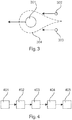
- FIG. 3 An example of a suitable beam shape for this purpose is in Fig. 3 shown.
- the main spot or main beam 301 is used to melt the material to be processed, and the two minor spots 302, 303 located laterally behind the main spot 301 serve to reduce the cooling gradient.
- the dashed line 304 indicates the area in which the material is liquid.
- the three laser spots move in the direction of the arrow to the left and come from the same laser source.
- Spatial light modulation can also be used to generate a beam profile, which is perceived as a line or spots 201, 202, 203, 204 arranged next to one another (cf. Fig. 2A ).
- the spots move, for example, perpendicular to their connecting line in the arrow direction down.
- optimal beam profiles can be provided and stored in the 3D printer or the welding device.
- the choice of the beam profile then takes place directly through the 3D printer or the welding device and thus remains independent of the so-called build processor. This saves considerable development effort on the build processor.
- Fig. 4 shows a flowchart of a method according to an embodiment of the invention.
- a laser beam is generated by a laser source.
- this laser beam is collimated and, in step 403, encounters a spatial light modulator that imposes spatial modulation on the laser beam to change the beam shape of the laser beam. For example, several separate laser beams can be generated from the one laser beam.
- the modified laser beam strikes the working plane. There is in the case of 3D printing a layer of the material to be processed or, in the case of the laser welding process, the weld to be produced.
- the Laser beam in the working plane moves to create a plane of the workpiece or to form the weld.
Abstract
3D-Drucker zur Herstellung eines dreidimensionalen Bauteils mittels eines selektiven Laser-Schmelzverfahrens mit einem Spatial-Light-Modulator, der eingerichtet ist, dem Laserstrahl eine räumliche Modulation aufzuprägen, so dass sich die Strahlform des auf die Arbeitsebene auftreffenden Laserstrahls einstellen lässt. Hierdurch kann der Temperaturgradient im Material abgeschwächt werden und/oder die belichtete Fläche vergrößert werden.3D printer for producing a three-dimensional component by means of a selective laser melting method with a spatial light modulator, which is designed to impart spatial modulation to the laser beam, so that the beam shape of the laser beam impinging on the working plane can be adjusted. As a result, the temperature gradient in the material can be attenuated and / or the exposed area can be increased.
Description
Die Erfindung betrifft den 3D-Druck. Insbesondere betrifft die Erfindung einen 3D-Drucker zur Herstellung eines dreidimensionalen Bauteils mittels eines selektiven Laser-Schmelzverfahrens, die Verwendung eines Spatial-Light-Modulators in einem 3D-Drucker zur Umformung eines Laserstrahls zur Herstellung eines dreidimensionalen Bauteils, ein Verfahren zur Herstellung eines dreidimensionalen Bauteils mittels eines selektiven Laser-Schmelzverfahrens oder eines Schweißverfahrens, ein Programmelement und ein computerlesbares Medium.The invention relates to 3D printing. In particular, the invention relates to a 3D printer for producing a three-dimensional component by means of a selective laser melting method, the use of a spatial light modulator in a 3D printer for forming a laser beam for producing a three-dimensional component, a method for producing a three-dimensional component by means of a selective laser melting process or a welding process, a program element and a computer-readable medium.
Das selektive Laserschmelzen (Englisch: Selective Laser Melting, Abkürzung SLM) ist ein generatives Fertigungsverfahren, das zur Gruppe der Strahlschmelzverfahren gehört. Beim selektiven Laserschmelzen wird der zu verarbeitende Werkstoff in Pulverform in einer dünnen Schicht auf einer Grundplatte aufgebracht. Der pulverförmige Werkstoff wird mittels Laserstrahlung lokal vollständig umgeschmolzen und bildet nach der Erstarrung eine feste Materialschicht. Anschließend wird die Grundplatte um den Betrag einer Schichtdicke abgesenkt und erneut Pulver aufgetragen. Dieser Zyklus wird so lange wiederholt, bis alle Schichten umgeschmolzen sind. Das fertige Bauteil wird vom überschüssigen Pulver gereinigt und nach Bedarf bearbeitet oder sofort verwendet.Selective Laser Melting (abbreviation SLM) is a generative manufacturing process that belongs to the group of beam melting processes. In selective laser melting, the material to be processed is applied in powder form in a thin layer on a base plate. The powdery material is completely remelted locally by means of laser radiation and forms a solid layer of material after solidification. Subsequently, the base plate is lowered by the amount of a layer thickness and applied powder again. This cycle is repeated until all layers have been remelted. The finished part is cleaned of excess powder and processed as needed or used immediately.
Die für den Aufbau des Bauteils typischen Schichtstärken bewegen sich für alle gängigen Materialien zwischen 20 und 100 µm.The layer thicknesses typical for the construction of the component are between 20 and 100 μm for all common materials.
Die durch selektives Laserschmelzen gefertigte Bauteile zeichnen sich durch große spezifische Dichten aus. Dies gewährleistet, dass die mechanischen Eigenschaften des generativ hergestellten Bauteils weitgehend denen des Grundwerkstoffs entsprechen.The components produced by selective laser melting are characterized by large specific densities. This ensures that the mechanical properties of the generatively produced component largely correspond to those of the base material.
Es ist eine Aufgabe der Erfindung, die Herstellung dreidimensionaler Bauteile zu verbessern.It is an object of the invention to improve the production of three-dimensional components.
Diese Aufgabe wird durch die Merkmale der unabhängigen Patentansprüche gelöst. Weiterbildungen der Erfindung ergeben sich aus den Unteransprüchen und der folgenden Beschreibung von Ausführungsformen.This object is solved by the features of the independent claims. Further developments of the invention will become apparent from the dependent claims and the following description of embodiments.
Ein erster Aspekt der Erfindung betrifft ein Fertigungssystem zur Herstellung eines dreidimensionalen Bauteils mittels eines selektiven Laser-Schmelzverfahrens. Das Fertigungssystem wird im Folgenden als 3D-Drucker bezeichnet.A first aspect of the invention relates to a manufacturing system for producing a three-dimensional component by means of a selective laser melting process. The manufacturing system is referred to below as a 3D printer.
Der 3D-Drucker weist eine oder mehrere Laserquellen auf, die eingerichtet sind zur Erzeugung eines oder mehrerer Laserstrahlen, die den "Druckvorgang" durchführen. Es ist eine Arbeitsebene vorgesehen, die eingerichtet ist zur Aufbringung einer Schicht des zu verarbeitenden Werkstoffs in Pulverform. Die Laserstrahlen werden auf die Arbeitsebene gelenkt, um den zu verarbeitenden Werkstoff in dieser Ebene an den gewünschten Stellen zu erhitzen, so dass das dreidimensionale Bauteil schichtweise hergestellt werden kann.The 3D printer has one or more laser sources configured to generate one or more laser beams that perform the "printing" operation. It is provided a working level, which is adapted for applying a layer of the material to be processed in powder form. The laser beams are directed to the working plane to the material to be processed in this plane to heat the desired locations, so that the three-dimensional component can be produced in layers.
Im Strahlengang eines jeden Lasers ist ein elektronisch ansteuerbares Umformmodul angeordnet, das eingerichtet ist, dem Laserstrahl eine räumliche Modulation aufzuprägen, so dass sich die Strahlform des auf die Arbeitsebene auftreffenden Laserstrahls einstellen lässt. Das elektronisch ansteuerbare Umformmodul ist ein Spatial-Light-Modulator, also ein räumlicher Modulator für Licht.In the beam path of each laser, an electronically controllable forming module is arranged, which is adapted to impart a spatial modulation to the laser beam, so that the beam shape of the impinging on the working plane laser beam can be adjusted. The electronically controllable forming module is a Spatial Light modulator, so a spatial modulator for light.
Hierbei handelt es sich um ein Bauteil, welches dem Laserlicht eine räumliche, elektronisch einstellbare Modulation aufprägt. Neben der Modulation der Intensität des Laserstrahls kann das Umformmodul auch ausgeführt sein, die Phase (zusätzlich oder alternativ zur Intensität) des Laserstrahls zu modulieren.This is a component which imparts a spatial, electronically adjustable modulation to the laser light. In addition to the modulation of the intensity of the laser beam, the forming module can also be designed to modulate the phase (in addition to or as an alternative to the intensity) of the laser beam.
Gemäß einer Ausführungsform der Erfindung weist der Laserstrahl bevor er fokussiert wird eine Leistungsdichte von mehr als 200 W/cm2 auf, beispielsweise mehr als 300 W/cm2. In der Arbeitsebene (also dort, wo der Strahl fokussiert ist) weist der Strahl eine Strahlintensität von weit mehr als 10E+05 bis 10E+06 W/cm2 auf. Bevor der Strahl fokussiert wird, weist er im kollimierten und unfokussierten Zustand - je nach Auslegung der optischen Komponenten - einen Durchmesser von 10 bis 20 mm auf. Bei Verwendung einer Laserleistung von 200 bis 500 W resultieren daraus maximale Leistungsdichten von 200 W/cm2 und mehr.According to one embodiment of the invention, the laser beam before being focused has a power density of more than 200 W / cm 2 , for example more than 300 W / cm 2 . In the working plane (ie where the beam is focused), the beam has a beam intensity of much more than 10E + 05 to 10E + 06 W / cm 2 . Before the beam is focused, it has a diameter of 10 to 20 mm in the collimated and unfocused state, depending on the design of the optical components. Using a laser power of 200 to 500 W results in maximum power densities of 200 W / cm 2 and more.
Da der Spatial-Light Modulator beispielsweise in jenem Teil des Strahlengangs zur Anwendung kommt, wo der Strahl den besagten Durchmesser von 10 bis 20 mm aufweist, kann dieses Modul für die laserbasierte 3D-Druckanwendung verwendet werden, da die Zerstörschwelle eines Spatial-Light Modulators in etwa bei 200 W/cm2 oder darüber liegt.For example, since the spatial light modulator is used in that part of the beam path where the beam has the said diameter of 10 to 20 mm, this module can be used for the laser-based 3D printing application since the damage threshold of a spatial light modulator in FIG is about 200 W / cm 2 or above.
Gemäß einer weiteren Ausführungsform der Erfindung ist der 3D-Drucker eingerichtet zum Erzeugen der Strahlform des auf die Arbeitsebene auftreffenden Laserstrahls in Form einer Linie. Oft wird bei dem SLM-Prozess mit einem Laser gearbeitet, bei dessen Anwendung in der Prozessebene (=Arbeitseben) ein nahezu kreisförmiger Laserspot entsteht. Mittels des Spatial-Light Modulators eröffnet sich nun die Möglichkeit, den Laserspot in der Arbeitseben so zu "formen", dass daraus eine linienförmige Verteilung der Intensität entsteht. Das menschliche Auge würde evtl. eine Linie wahrnehmen. Verwendet man nun besonders leistungsstarke Laser, kann man innerhalb der Linie eine Intensität erzeugen, die ausreichend ist, um das Material aufzuschmelzen. Das bedeutet, dass sich der Prozess erheblich effizienter gestalten lässt, da bei Verwendung einer "Linienquelle" gegenüber der Verwendung einer Punktquelle deutlich schneller Fläche/Zeit belichtet werden kann.According to a further embodiment of the invention, the 3D printer is designed to generate the beam shape of the laser beam impinging on the working plane in the form of a line. Often, the SLM process uses a laser that, when used in the process level (= working plane), produces a nearly circular laser spot. The Spatial Light Modulator now opens up the possibility of "shaping" the laser spot in the working plane so that a linear distribution of the intensity results. The human eye would possibly perceive a line. Using high performance lasers, you can create an intensity within the line that is sufficient to melt the material. This means that the process can be made considerably more efficient, since the use of a "line source" can expose area / time much faster than using a point source.
Alternativ oder zusätzlich kann er eingerichtet sein, die Strahlform des auf die Arbeitsebene auftreffenden Laserstrahls in Form mehrerer nebeneinander angeordneter Laserspots zu erzeugen.Alternatively or additionally, it can be set up to generate the beam shape of the laser beam impinging on the working plane in the form of a plurality of laser spots arranged next to one another.
Auch kann er eingerichtet sein, die Strahlform in Form von drei Laserspots zu erzeugen, wobei zwei der Laserspots einen geringeren Durchmesser aufweisen können als der dritte Laserspot und die Mittelpunkte der drei Spots ein Dreieck ausbilden, so dass über die zwei kleineren Spots der Temperaturgradient im zu verarbeitenden Werkstoff gesteuert werden kann, um die Auftrittswahrscheinlichkeit von Heißrissen zu senken.It can also be set up to generate the beam shape in the form of three laser spots, wherein two of the laser spots can have a smaller diameter than the third laser spot and the centers of the three spots form a triangle, so that over the two smaller spots of the temperature gradient in processing material can be controlled to reduce the probability of occurrence of hot cracks.
Im Erstarrungsbereich des Schmelzbads, welches durch den Hauptspot erzeugt wird, können transversale Dehnungen auftreten, die ursächlich sind für longitudinal auftretende Heißrisse. Die beiden kleineren Spots, welche den Hauptspot mit einem zu definierenden Offset begleiten, dienen in erster Linie dazu, Wärme um den Erstarrungsbereich einzukoppeln, um die in Folge der induzierten Wärme einhergehende thermische Ausdehnung des Materials dafür zu nutzen, der transversalen Ausdehnung des Materials im Erstarrungsbereich entgegenzuwirken. Ein weiterer Aspekt der Erfindung betrifft die Verwendung eines Spatial-Light-Modulators in einem 3D-Drucker zur Umformung eines Laserstrahls zur Herstellung eines dreidimensionalen Bauteils.In the solidification zone of the molten bath, which is generated by the main spot, transverse strains can occur, which are the cause of longitudinally occurring hot cracks. The two smaller spots, which accompany the main spot with an offset to be defined, serve primarily to couple heat around the solidification area to those induced as a result of the induced heat accompanying thermal expansion of the material to counteract the transverse expansion of the material in the solidification range. Another aspect of the invention relates to the use of a spatial light modulator in a 3D printer for forming a laser beam for producing a three-dimensional component.
Ein weiterer Aspekt der Erfindung betrifft die Verwendung eines Spatial-Light-Modulators in einem Laserstrahlschweißgerät zur Umformung eines Laserstrahls zur Verschweißung zweier Bauteile miteinander.Another aspect of the invention relates to the use of a Spatial Light modulator in a laser beam welding apparatus for forming a laser beam for welding two components together.
Ein weiterer Aspekt der Erfindung betrifft ein Verfahren zur Herstellung eines dreidimensionalen Bauteils mittels eines selektiven Laser-Schmelzverfahrens oder eines Schweißverfahrens, bei dem ein Laserstrahl zum Erhitzen eines zu verarbeitenden Werkstoffs erzeugt wird und dem Laserstrahl eine räumliche Modulation durch ein elektronisch ansteuerbares Umformmodul, das im Strahlengang des Laserstrahls angeordnet ist, aufgeprägt wird. Hierdurch wird erreicht, dass die Strahlform des auf eine Arbeitsebene auftreffenden Laserstrahls elektronisch eingestellt wird. Bei dem elektronisch ansteuerbaren Umformmodul handelt es sich um einen Spatial-Light-Modulator.A further aspect of the invention relates to a method for producing a three-dimensional component by means of a selective laser melting method or a welding method in which a laser beam is generated for heating a material to be processed and the laser beam spatial modulation by an electronically controllable forming module in the beam path of the laser beam is arranged, is impressed. This ensures that the beam shape of the impinging on a working plane laser beam is electronically adjusted. The electronically controllable forming module is a spatial light modulator.
Ein weiterer Aspekt der Erfindung betrifft ein Programmelement, das, wenn es auf einem Prozessor eines 3D-Druckers oder einem Laserstrahlschweißgerät ausgeführt wird, den 3D-Drucker oder das Laserstrahlschweißgerät anleitet, die oben und im Folgenden beschriebenen Schritte durchzuführen.Another aspect of the invention relates to a program element that, when executed on a processor of a 3D printer or a laser beam welder, instructs the 3D printer or laser beam welder to perform the steps described above and below.
Ein weiterer Aspekt der Erfindung betrifft ein computerlesbares Medium, auf dem das oben beschriebene Programmelement gespeichert ist.A further aspect of the invention relates to a computer-readable medium on which the program element described above is stored.
Im Folgenden werden weitere Ausführungsformen der Erfindung näher beschrieben. Die Darstellungen in den Figuren sind schematisch und nicht maßstäblich.In the following, further embodiments of the invention will be described in more detail. The illustrations in the figures are schematic and not to scale.
-
Fig. 1 zeigt eine schematische Darstellung eines 3D-Druckers bzw. eines Laserstrahlschweißgeräts gemäß einer Ausführungsform der Erfindung.Fig. 1 shows a schematic representation of a 3D printer or a laser beam welding apparatus according to an embodiment of the invention. -
Fig. 2A bis 2D zeigen die Strahlformen eines auf die Arbeitsebene auftreffenden Laserstrahls gemäß mehrerer Ausführungsformen der Erfindung.Fig. 2A to 2D show the beam shapes of a laser beam impinging on the working plane according to several embodiments of the invention. -
Fig. 3 zeigt die Strahlform eines auf die Arbeitsebene auftreffenden Laserstrahls gemäß einer weiteren Ausführungsform der Erfindung.Fig. 3 shows the beam shape of an incident on the working plane laser beam according to another embodiment of the invention. -
Fig. 4 zeigt ein Flussdiagramm eines Verfahrens gemäß einer Ausführungsform der Erfindung.Fig. 4 shows a flowchart of a method according to an embodiment of the invention.
Derselbe oder ein ähnlicher Aufbau kann auch für ein Laserstrahlschweißgerät verwendet werden.The same or similar structure may be used for a laser beam welder.
Bei dem selektiven Laser-Schmelzverfahren wird in aller Regel mit einem oder mehreren Single-Mode-Lasern 101 gearbeitet werden, welche den Laserstrahl 105 erzeugen. Bei diesem Single-Mode-Laser schwingt nur eine transversale Mode an. Standardmäßig handelt es sich hierbei um die Gauß-Mode (TEMoo). Es können auch SLM-Systeme verwendet werden, die mit extrem leistungsstarken Lasern arbeiten. Hier ist die Verwendung eines Multi-Moden-Lasers nicht unüblich, so dass der Strahl ggf. Abweichungen zum idealen Gaußstrahl (TEMoo) aufweist.In the selective laser melting process, as a rule, one or more single-
Der kollimierte Laserstrahl 105 trifft auf einen im Strahlengang des Lasers angeordneten Spatial-Light-Modulator -Chip 103. Bei diesem Spatial-Light-Modulator Chip handelt es sich um ein Modul, auf dessen Ebene der Laserstrahl beispielsweise unter einem Winkel von 45° auftrifft.The collimated
Im Spatial-Light-Modulator 103 befindet sich beispielsweise eine C-MOS-Schaltung 113 mit einer Pixelelektrode 114. Oberhalb der Pixelelektrode befindet sich eine Flüssigkristallschicht 112, und darüber eine transparente Elektrode 111, die auf einem Glassubstrat 110 aufgebracht ist.In the spatial
Der Spatial-Light-Modulator 103 wird von dem Prozessor 107 gesteuert, so dass sich verschiedene Strahlformen erzeugen lassen. Ein Beispiel einer solchen Strahlform ist mit Bezugszeichen 120 bezeichnet.The spatial
Der umgeformte Laserstrahl wird über eine Optik 104 auf den entsprechenden Arbeitspunkt 106 in der Arbeitsebene 102 gelenkt, um den Werkstoff aufzuschmelzen.The reshaped laser beam is directed via an optic 104 to the
Hohe Abkühlgradienten sind ein Wesensmerkmal des SLM-Prozesses. Als Folge davon können hohe Dehnungen und Dehnraten im Material auftreten, die sich insbesondere bei heißrisssensitiven Materialien nachteilig auf die Qualität des Gefüges auswirken können. Durch den Gauß-Strahl, der vom Laser ausgeht, erfolgt die großflächige Belichtung von Pulverschichten verhältnismäßig langsam, was eine geringe Produktivität des Fertigungsprozesses zur Folge hat.High cooling gradients are an essential feature of the SLM process. As a result, high strains and strain rates can occur in the material, which can have a detrimental effect on the quality of the structure, especially in Heißrisssensitive materials. Due to the Gaussian beam emanating from the laser, the large-area exposure of powder layers is relatively slow, resulting in low productivity of the manufacturing process.
Zur Umformung des Laserstrahls wird Spatial-Light-Modulation eingesetzt. Das Modul 103 ist hierbei ausgeführt, dass es bei üblichen Leistungsdichten von 200 bis 300 W/cm2 oder darüber verwendet werden kann.Spatial light modulation is used to reshape the laser beam. The
Anstelle des Gauß-Strahls wird die Belichtung mittels des durch den Spatial-Light-Modulator 103 umgeformten Laserstrahls durchgeführt. Dadurch lassen sich nahezu beliebige Strahlformen (= Intensitätsverteilungen) realisieren. Je nach Anwendungsfall lassen sich damit im SLM-Prozess erhebliche Vorteile erzielen.Instead of the Gaussian beam, the exposure is carried out by means of the laser beam converted by the spatial-
So lassen sich beispielsweise Reduktionen der ansonsten sehr hohen Dehnungen und Dehnraten thermisch durch einen reduzierten Abkühlgradienten verwirklichen. Wird also nun ein Strahlprofil (Strahlform) erzeugt, welches ein Nachheizen des Schmelzbades sowie der wärmebeeinflussten Zone realisiert, können als Folge auch geringere Dehnungen und Dehnraten auftreten, so dass zugleich auch die Auftrittswahrscheinlichkeit von Heißrissen sinkt.Thus, for example, reductions of the otherwise very high strains and strain rates can be achieved thermally by a reduced cooling gradient. If, therefore, a beam profile (beam shape) is produced which realizes a reheating of the molten bath and of the heat-affected zone, as a consequence also lower strains and strain rates can occur, so that at the same time the probability of occurrence of hot cracks decreases.
Ein Beispiel für eine hierfür geeignete Strahlform ist in
Mittels Spatial-Light-Modulation kann auch ein Strahlprofil erzeugt werden, welches als Linie oder nebeneinander angeordnete Spots 201, 202, 203, 204 wahrgenommen wird (vgl.
Der Einsatz der Spatial-Light-Modulation bietet sehr vielseitige Möglichkeiten der Strahlgestaltung und erlaubt damit die Umsetzung komplexer Strategien, die Temperaturgradienten während des Schichtaufbaus und der Erstarrung des Materials zu beeinflussen. Im Folgenden werden konkret Möglichkeiten der Strahlgestaltung aufgeführt.
- 1. Die Verwendung eines im Querschnitt ovalen Strahlprofils mit der in
Fig. 2B aufgeführten Intensitätsverteilung. Mit Hilfe dieses Strahlprofils ist ein geführtes Abkühlverhalten möglich. - 2. Die Verwendung eines Strahls mit mehreren Intensitätsmaxima in der betreffenden Arbeitsebene, wie dies beispielhaft in
Fig. 2C gezeigt ist. Diese Art Strahl bzw. Intensitätsverteilung ist ansonsten nur durch eine Komposition von zwei oder mehreren Strahlen möglich.
- 1. The use of a cross-sectionally oval beam profile with the in
Fig. 2B listed intensity distribution. With the help of this beam profile, a guided cooling behavior is possible. - 2. The use of a beam with multiple intensity maxima in the relevant working plane, as exemplified in
Fig. 2C is shown. This type of beam or intensity distribution is otherwise possible only by a composition of two or more beams.
Zudem besteht auch die Möglichkeit, den SLM-Prozess wesentlich produktiver zu gestalten, da man sehr hohe Laserleistungen als Linienprofil in das Material einkoppeln kann. Im Folgenden werden konkret Möglichkeiten der Strahlgestaltung aufgeführt.
- 1. Verwendung eines im Querschnitt runden oder rechteckigen Top-Hat bzw. Flat-Top-Profils
Fig. 2D . Daraus resultiert ein gleichmäßigerer Eintrag der Laserenergie ins Material und ermöglicht die Einkopplung höher Laserleistungen pro Fläche, woraus sich schlussendlich ein produktiverer Prozess ableiten lässt. - 2. Die Verwendung von in Reihe geschalteten Profilen, so dass gleich mehrere nebeneinanderliegende Schmelzbäder erzeugt werden
Fig. 2A .
- 1. Use of a cross-sectionally round or rectangular top hat or flat top profile
Fig. 2D , This results in a more uniform entry of the laser energy into the material and enables the coupling of higher laser powers per surface, which ultimately leads to a more productive process. - 2. The use of in-line profiles, so that several adjacent adjacent melt baths are generated
Fig. 2A ,
Für bestimmte Materialien können optimale Strahlprofile vorgesehen und im 3D-Drucker bzw. dem Schweißgerät gespeichert sein. Die Wahl des Strahlprofils erfolgt dann unmittelbar durch den 3D-Drucker bzw. das Schweißgerät und bleibt damit unabhängig vom sogenannten Build-Prozessor. Dadurch erspart man sich erhebliche Entwicklungsaufwände beim Build-Prozessor.For certain materials, optimal beam profiles can be provided and stored in the 3D printer or the welding device. The choice of the beam profile then takes place directly through the 3D printer or the welding device and thus remains independent of the so-called build processor. This saves considerable development effort on the build processor.
Beim Laserstrahlschweißen und SLM hat sich herausgestellt, dass bei niedrigeren Geschwindigkeiten des Laserspots bestimmte Entmischungen im Erstarrungsbereich der Schweißnahtmitte auftreten können. Es entstehen demnach Korngrenzen, die zum Zeitpunkt ihrer Entstehung noch mit einem flüssigen Film benetzt sind und gleichzeitig aufgrund der vorhandenen Abkühlung mit ungünstigen Dehnungen überlagert werden können. Diese Dehnungen zerren an der Korngrenze und führen im ungünstigsten Fall zu einer Öffnung derselben, was dann im Allgemeinen als Heißriss wahrgenommen wird.In laser beam welding and SLM, it has been found that at lower speeds of the laser spot certain segregations may occur in the solidification region of the weld center. This results in grain boundaries that are wetted with a liquid film at the time of their formation and can be superimposed at the same time due to the existing cooling with unfavorable strains. These strains tear at the grain boundary and, in the worst case, result in an opening thereof, which is then generally perceived as a hot crack.
Um dieser Heißrissneigung entgegenzuwirken, wird seitlich der Nahtmitte Wärme mittels weiterer Laserspots 302, 303 induziert (vgl.
Ergänzend sei darauf hingewiesen, dass "umfassend" und "aufweisend" keine anderen Elemente oder Schritte ausschließt und die unbestimmten Artikel "eine" oder "ein" keine Vielzahl ausschließen. Ferner sei daraufhingewiesen, dass Merkmale oder Schritte, die mit Verweis auf eines der obigen Ausführungsbeispiele beschrieben worden sind, auch in Kombination mit anderen Merkmalen oder Schritten anderer oben beschriebener Ausführungsbeispiele verwendet werden können. Bezugszeichen in den Ansprüchen sind nicht als Einschränkungen anzusehen.In addition, it should be noted that "comprising" and "having" does not exclude other elements or steps, and the indefinite articles "a" or "an" exclude no plurality. It should also be appreciated that features or steps described with reference to any of the above embodiments may also be used in combination with other features or steps of other embodiments described above. Reference signs in the claims are not to be considered as limitations.
Claims (10)
Priority Applications (1)
| Application Number | Priority Date | Filing Date | Title |
|---|---|---|---|
| EP18154428.9A EP3520927B1 (en) | 2018-01-31 | 2018-01-31 | 3d printer comprising an electronically controllable moulding module |
Applications Claiming Priority (1)
| Application Number | Priority Date | Filing Date | Title |
|---|---|---|---|
| EP18154428.9A EP3520927B1 (en) | 2018-01-31 | 2018-01-31 | 3d printer comprising an electronically controllable moulding module |
Publications (2)
| Publication Number | Publication Date |
|---|---|
| EP3520927A1 true EP3520927A1 (en) | 2019-08-07 |
| EP3520927B1 EP3520927B1 (en) | 2020-07-29 |
Family
ID=61132162
Family Applications (1)
| Application Number | Title | Priority Date | Filing Date |
|---|---|---|---|
| EP18154428.9A Active EP3520927B1 (en) | 2018-01-31 | 2018-01-31 | 3d printer comprising an electronically controllable moulding module |
Country Status (1)
| Country | Link |
|---|---|
| EP (1) | EP3520927B1 (en) |
Citations (7)
| Publication number | Priority date | Publication date | Assignee | Title |
|---|---|---|---|---|
| US20030052105A1 (en) * | 2001-09-10 | 2003-03-20 | Fuji Photo Film Co., Ltd. | Laser sintering apparatus |
| JP2003094185A (en) * | 2001-09-25 | 2003-04-02 | Nippon Steel Corp | Apparatus and method for lap laser-beam welding for galvanized steel sheet |
| US20160243649A1 (en) * | 2014-07-10 | 2016-08-25 | Guangzhou Institute of Advanced Technology, Chinise Academy of Sciences | Optical system for 3d printing and control method thereof |
| WO2017015241A1 (en) * | 2015-07-18 | 2017-01-26 | Vulcanforms Inc. | Additive manufacturing by spatially controlled material fusion |
| US9636775B2 (en) * | 2014-12-24 | 2017-05-02 | Industrial Technology Research Institute | Composite beam generator and powder melting or sintering method using the same |
| EP3219412A1 (en) * | 2014-11-14 | 2017-09-20 | Nikon Corporation | Shaping device and a shaping method |
| DE102016213420A1 (en) * | 2016-07-22 | 2018-01-25 | Robert Bosch Gmbh | Method and device for the generative production of a component |
Family Cites Families (1)
| Publication number | Priority date | Publication date | Assignee | Title |
|---|---|---|---|---|
| CA2957719A1 (en) * | 2014-08-13 | 2016-02-18 | Ipg Photonics Corporation | Multibeam fiber laser system |
-
2018
- 2018-01-31 EP EP18154428.9A patent/EP3520927B1/en active Active
Patent Citations (7)
| Publication number | Priority date | Publication date | Assignee | Title |
|---|---|---|---|---|
| US20030052105A1 (en) * | 2001-09-10 | 2003-03-20 | Fuji Photo Film Co., Ltd. | Laser sintering apparatus |
| JP2003094185A (en) * | 2001-09-25 | 2003-04-02 | Nippon Steel Corp | Apparatus and method for lap laser-beam welding for galvanized steel sheet |
| US20160243649A1 (en) * | 2014-07-10 | 2016-08-25 | Guangzhou Institute of Advanced Technology, Chinise Academy of Sciences | Optical system for 3d printing and control method thereof |
| EP3219412A1 (en) * | 2014-11-14 | 2017-09-20 | Nikon Corporation | Shaping device and a shaping method |
| US9636775B2 (en) * | 2014-12-24 | 2017-05-02 | Industrial Technology Research Institute | Composite beam generator and powder melting or sintering method using the same |
| WO2017015241A1 (en) * | 2015-07-18 | 2017-01-26 | Vulcanforms Inc. | Additive manufacturing by spatially controlled material fusion |
| DE102016213420A1 (en) * | 2016-07-22 | 2018-01-25 | Robert Bosch Gmbh | Method and device for the generative production of a component |
Non-Patent Citations (1)
| Title |
|---|
| POHL R ET AL: "Solid-phase laser-induced forward transfer of variable shapes using a liquid-crystal spatial light modulator", APPLIED PHYSICS A MATERIALS SCIENCE & PROCESSING, SPRINGER BERLIN HEIDELBERG, BERLIN/HEIDELBERG, vol. 120, no. 2, 12 May 2015 (2015-05-12), pages 427 - 434, XP035516347, ISSN: 0947-8396, [retrieved on 20150512], DOI: 10.1007/S00339-015-9212-2 * |
Also Published As
| Publication number | Publication date |
|---|---|
| EP3520927B1 (en) | 2020-07-29 |
Similar Documents
| Publication | Publication Date | Title |
|---|---|---|
| EP3221727B1 (en) | System for asymmetric optical beam shaping | |
| EP2335848B1 (en) | Optical irradiation unit for an assembly for producing workpieces by means of irradiating powder layers with laser radiation | |
| DE102006053898B4 (en) | Laser processing device and laser processing method | |
| EP3221739A1 (en) | Diffractive optical beam-shaping element | |
| WO2016128430A1 (en) | Irradiation apparatus, processing machine and method for creating a layer or a section of a layer of a three-dimensional component | |
| DE102007061549B4 (en) | Method for changing the beam diameter of a laser beam in a working plane and arrangement designed for this purpose | |
| DE102019217577A1 (en) | Process for laser processing of a workpiece, processing optics and laser processing device | |
| DE112014001676T5 (en) | LASER PROCESSING DEVICE AND LASER PROCESSING METHOD | |
| DE102006042280A1 (en) | Transparent material scribing comprises using single scan of focused beam of ultrashort laser pulses to simultaneously create surface groove in material and modified region(s) within bulk of material | |
| DE112014001688T5 (en) | Laser processing device and laser processing method | |
| DE112014001710T5 (en) | Laser processing device and laser processing method | |
| DE102014201715A1 (en) | Method and device for spot welding of workpieces by means of laser pulses with green wavelength | |
| DE102014203025A1 (en) | Method for laser beam welding and welding head | |
| WO2018219710A1 (en) | Method for the deep welding of a workpiece, with distribution of the laser power over a number of focal points | |
| EP3274121A1 (en) | Laser beam joining method and laser machining optics | |
| DE102010007323A1 (en) | Method for determining the cutting result of a laser cutting process | |
| DE112014001653T5 (en) | Laser processing device and laser processing method | |
| DE212013000142U1 (en) | System for edge forming and plating operations | |
| DE102013011675A1 (en) | Method for additive component production with reduced thermal gradients | |
| DE102019125103A1 (en) | Processing device for laser processing of a workpiece, method for laser processing of a workpiece | |
| DE102016213420A1 (en) | Method and device for the generative production of a component | |
| EP3346314B1 (en) | Device and method for forming a laser beam by means of a programmable beam former | |
| WO2020254639A1 (en) | Method and device for processing a workpiece with a processing beam composed of at least two beam profiles | |
| DE19751195C1 (en) | Method and device for welding by means of laser radiation | |
| EP3520927B1 (en) | 3d printer comprising an electronically controllable moulding module |
Legal Events
| Date | Code | Title | Description |
|---|---|---|---|
| PUAI | Public reference made under article 153(3) epc to a published international application that has entered the european phase |
Free format text: ORIGINAL CODE: 0009012 |
|
| STAA | Information on the status of an ep patent application or granted ep patent |
Free format text: STATUS: REQUEST FOR EXAMINATION WAS MADE |
|
| 17P | Request for examination filed |
Effective date: 20190124 |
|
| AK | Designated contracting states |
Kind code of ref document: A1 Designated state(s): AL AT BE BG CH CY CZ DE DK EE ES FI FR GB GR HR HU IE IS IT LI LT LU LV MC MK MT NL NO PL PT RO RS SE SI SK SM TR |
|
| AX | Request for extension of the european patent |
Extension state: BA ME |
|
| STAA | Information on the status of an ep patent application or granted ep patent |
Free format text: STATUS: EXAMINATION IS IN PROGRESS |
|
| 17Q | First examination report despatched |
Effective date: 20190923 |
|
| RIC1 | Information provided on ipc code assigned before grant |
Ipc: B22F 7/06 20060101ALI20200109BHEP Ipc: B29C 64/153 20170101ALI20200109BHEP Ipc: B22F 3/105 20060101AFI20200109BHEP Ipc: B22F 7/08 20060101ALI20200109BHEP Ipc: B33Y 10/00 20150101ALI20200109BHEP |
|
| GRAP | Despatch of communication of intention to grant a patent |
Free format text: ORIGINAL CODE: EPIDOSNIGR1 |
|
| STAA | Information on the status of an ep patent application or granted ep patent |
Free format text: STATUS: GRANT OF PATENT IS INTENDED |
|
| INTG | Intention to grant announced |
Effective date: 20200218 |
|
| GRAS | Grant fee paid |
Free format text: ORIGINAL CODE: EPIDOSNIGR3 |
|
| GRAA | (expected) grant |
Free format text: ORIGINAL CODE: 0009210 |
|
| STAA | Information on the status of an ep patent application or granted ep patent |
Free format text: STATUS: THE PATENT HAS BEEN GRANTED |
|
| AK | Designated contracting states |
Kind code of ref document: B1 Designated state(s): AL AT BE BG CH CY CZ DE DK EE ES FI FR GB GR HR HU IE IS IT LI LT LU LV MC MK MT NL NO PL PT RO RS SE SI SK SM TR |
|
| REG | Reference to a national code |
Ref country code: CH Ref legal event code: EP |
|
| REG | Reference to a national code |
Ref country code: AT Ref legal event code: REF Ref document number: 1295208 Country of ref document: AT Kind code of ref document: T Effective date: 20200815 |
|
| REG | Reference to a national code |
Ref country code: IE Ref legal event code: FG4D Free format text: LANGUAGE OF EP DOCUMENT: GERMAN |
|
| REG | Reference to a national code |
Ref country code: DE Ref legal event code: R096 Ref document number: 502018001971 Country of ref document: DE |
|
| REG | Reference to a national code |
Ref country code: CH Ref legal event code: NV Representative=s name: ING. MARCO ZARDI C/O M. ZARDI AND CO. S.A., CH |
|
| REG | Reference to a national code |
Ref country code: LT Ref legal event code: MG4D |
|
| REG | Reference to a national code |
Ref country code: NL Ref legal event code: MP Effective date: 20200729 |
|
| PG25 | Lapsed in a contracting state [announced via postgrant information from national office to epo] |
Ref country code: BG Free format text: LAPSE BECAUSE OF FAILURE TO SUBMIT A TRANSLATION OF THE DESCRIPTION OR TO PAY THE FEE WITHIN THE PRESCRIBED TIME-LIMIT Effective date: 20201029 Ref country code: NO Free format text: LAPSE BECAUSE OF FAILURE TO SUBMIT A TRANSLATION OF THE DESCRIPTION OR TO PAY THE FEE WITHIN THE PRESCRIBED TIME-LIMIT Effective date: 20201029 Ref country code: GR Free format text: LAPSE BECAUSE OF FAILURE TO SUBMIT A TRANSLATION OF THE DESCRIPTION OR TO PAY THE FEE WITHIN THE PRESCRIBED TIME-LIMIT Effective date: 20201030 Ref country code: LT Free format text: LAPSE BECAUSE OF FAILURE TO SUBMIT A TRANSLATION OF THE DESCRIPTION OR TO PAY THE FEE WITHIN THE PRESCRIBED TIME-LIMIT Effective date: 20200729 Ref country code: HR Free format text: LAPSE BECAUSE OF FAILURE TO SUBMIT A TRANSLATION OF THE DESCRIPTION OR TO PAY THE FEE WITHIN THE PRESCRIBED TIME-LIMIT Effective date: 20200729 Ref country code: PT Free format text: LAPSE BECAUSE OF FAILURE TO SUBMIT A TRANSLATION OF THE DESCRIPTION OR TO PAY THE FEE WITHIN THE PRESCRIBED TIME-LIMIT Effective date: 20201130 Ref country code: SE Free format text: LAPSE BECAUSE OF FAILURE TO SUBMIT A TRANSLATION OF THE DESCRIPTION OR TO PAY THE FEE WITHIN THE PRESCRIBED TIME-LIMIT Effective date: 20200729 Ref country code: FI Free format text: LAPSE BECAUSE OF FAILURE TO SUBMIT A TRANSLATION OF THE DESCRIPTION OR TO PAY THE FEE WITHIN THE PRESCRIBED TIME-LIMIT Effective date: 20200729 Ref country code: ES Free format text: LAPSE BECAUSE OF FAILURE TO SUBMIT A TRANSLATION OF THE DESCRIPTION OR TO PAY THE FEE WITHIN THE PRESCRIBED TIME-LIMIT Effective date: 20200729 |
|
| PG25 | Lapsed in a contracting state [announced via postgrant information from national office to epo] |
Ref country code: IS Free format text: LAPSE BECAUSE OF FAILURE TO SUBMIT A TRANSLATION OF THE DESCRIPTION OR TO PAY THE FEE WITHIN THE PRESCRIBED TIME-LIMIT Effective date: 20201129 Ref country code: PL Free format text: LAPSE BECAUSE OF FAILURE TO SUBMIT A TRANSLATION OF THE DESCRIPTION OR TO PAY THE FEE WITHIN THE PRESCRIBED TIME-LIMIT Effective date: 20200729 Ref country code: RS Free format text: LAPSE BECAUSE OF FAILURE TO SUBMIT A TRANSLATION OF THE DESCRIPTION OR TO PAY THE FEE WITHIN THE PRESCRIBED TIME-LIMIT Effective date: 20200729 Ref country code: LV Free format text: LAPSE BECAUSE OF FAILURE TO SUBMIT A TRANSLATION OF THE DESCRIPTION OR TO PAY THE FEE WITHIN THE PRESCRIBED TIME-LIMIT Effective date: 20200729 |
|
| PG25 | Lapsed in a contracting state [announced via postgrant information from national office to epo] |
Ref country code: NL Free format text: LAPSE BECAUSE OF FAILURE TO SUBMIT A TRANSLATION OF THE DESCRIPTION OR TO PAY THE FEE WITHIN THE PRESCRIBED TIME-LIMIT Effective date: 20200729 |
|
| PG25 | Lapsed in a contracting state [announced via postgrant information from national office to epo] |
Ref country code: SM Free format text: LAPSE BECAUSE OF FAILURE TO SUBMIT A TRANSLATION OF THE DESCRIPTION OR TO PAY THE FEE WITHIN THE PRESCRIBED TIME-LIMIT Effective date: 20200729 Ref country code: RO Free format text: LAPSE BECAUSE OF FAILURE TO SUBMIT A TRANSLATION OF THE DESCRIPTION OR TO PAY THE FEE WITHIN THE PRESCRIBED TIME-LIMIT Effective date: 20200729 Ref country code: DK Free format text: LAPSE BECAUSE OF FAILURE TO SUBMIT A TRANSLATION OF THE DESCRIPTION OR TO PAY THE FEE WITHIN THE PRESCRIBED TIME-LIMIT Effective date: 20200729 Ref country code: CZ Free format text: LAPSE BECAUSE OF FAILURE TO SUBMIT A TRANSLATION OF THE DESCRIPTION OR TO PAY THE FEE WITHIN THE PRESCRIBED TIME-LIMIT Effective date: 20200729 Ref country code: EE Free format text: LAPSE BECAUSE OF FAILURE TO SUBMIT A TRANSLATION OF THE DESCRIPTION OR TO PAY THE FEE WITHIN THE PRESCRIBED TIME-LIMIT Effective date: 20200729 Ref country code: IT Free format text: LAPSE BECAUSE OF FAILURE TO SUBMIT A TRANSLATION OF THE DESCRIPTION OR TO PAY THE FEE WITHIN THE PRESCRIBED TIME-LIMIT Effective date: 20200729 |
|
| REG | Reference to a national code |
Ref country code: DE Ref legal event code: R097 Ref document number: 502018001971 Country of ref document: DE |
|
| PG25 | Lapsed in a contracting state [announced via postgrant information from national office to epo] |
Ref country code: AL Free format text: LAPSE BECAUSE OF FAILURE TO SUBMIT A TRANSLATION OF THE DESCRIPTION OR TO PAY THE FEE WITHIN THE PRESCRIBED TIME-LIMIT Effective date: 20200729 |
|
| PLBE | No opposition filed within time limit |
Free format text: ORIGINAL CODE: 0009261 |
|
| STAA | Information on the status of an ep patent application or granted ep patent |
Free format text: STATUS: NO OPPOSITION FILED WITHIN TIME LIMIT |
|
| PG25 | Lapsed in a contracting state [announced via postgrant information from national office to epo] |
Ref country code: SK Free format text: LAPSE BECAUSE OF FAILURE TO SUBMIT A TRANSLATION OF THE DESCRIPTION OR TO PAY THE FEE WITHIN THE PRESCRIBED TIME-LIMIT Effective date: 20200729 |
|
| 26N | No opposition filed |
Effective date: 20210430 |
|
| PG25 | Lapsed in a contracting state [announced via postgrant information from national office to epo] |
Ref country code: SI Free format text: LAPSE BECAUSE OF FAILURE TO SUBMIT A TRANSLATION OF THE DESCRIPTION OR TO PAY THE FEE WITHIN THE PRESCRIBED TIME-LIMIT Effective date: 20200729 Ref country code: MC Free format text: LAPSE BECAUSE OF FAILURE TO SUBMIT A TRANSLATION OF THE DESCRIPTION OR TO PAY THE FEE WITHIN THE PRESCRIBED TIME-LIMIT Effective date: 20200729 |
|
| PG25 | Lapsed in a contracting state [announced via postgrant information from national office to epo] |
Ref country code: LU Free format text: LAPSE BECAUSE OF NON-PAYMENT OF DUE FEES Effective date: 20210131 |
|
| PG25 | Lapsed in a contracting state [announced via postgrant information from national office to epo] |
Ref country code: IE Free format text: LAPSE BECAUSE OF NON-PAYMENT OF DUE FEES Effective date: 20210131 |
|
| PGFP | Annual fee paid to national office [announced via postgrant information from national office to epo] |
Ref country code: FR Payment date: 20230123 Year of fee payment: 6 Ref country code: CH Payment date: 20230130 Year of fee payment: 6 |
|
| PGFP | Annual fee paid to national office [announced via postgrant information from national office to epo] |
Ref country code: GB Payment date: 20230124 Year of fee payment: 6 Ref country code: DE Payment date: 20230130 Year of fee payment: 6 Ref country code: BE Payment date: 20230123 Year of fee payment: 6 |
|
| P01 | Opt-out of the competence of the unified patent court (upc) registered |
Effective date: 20230504 |
|
| PG25 | Lapsed in a contracting state [announced via postgrant information from national office to epo] |
Ref country code: CY Free format text: LAPSE BECAUSE OF FAILURE TO SUBMIT A TRANSLATION OF THE DESCRIPTION OR TO PAY THE FEE WITHIN THE PRESCRIBED TIME-LIMIT Effective date: 20200729 |
|
| PG25 | Lapsed in a contracting state [announced via postgrant information from national office to epo] |
Ref country code: HU Free format text: LAPSE BECAUSE OF FAILURE TO SUBMIT A TRANSLATION OF THE DESCRIPTION OR TO PAY THE FEE WITHIN THE PRESCRIBED TIME-LIMIT; INVALID AB INITIO Effective date: 20180131 |
|
| REG | Reference to a national code |
Ref country code: AT Ref legal event code: MM01 Ref document number: 1295208 Country of ref document: AT Kind code of ref document: T Effective date: 20230131 |