EP3520925A1 - Procédé de fabrication de vilebrequin forgé - Google Patents
Procédé de fabrication de vilebrequin forgé Download PDFInfo
- Publication number
- EP3520925A1 EP3520925A1 EP17855722.9A EP17855722A EP3520925A1 EP 3520925 A1 EP3520925 A1 EP 3520925A1 EP 17855722 A EP17855722 A EP 17855722A EP 3520925 A1 EP3520925 A1 EP 3520925A1
- Authority
- EP
- European Patent Office
- Prior art keywords
- pin
- preform
- die
- journal
- region
- Prior art date
- Legal status (The legal status is an assumption and is not a legal conclusion. Google has not performed a legal analysis and makes no representation as to the accuracy of the status listed.)
- Withdrawn
Links
Images


Classifications
-
- B—PERFORMING OPERATIONS; TRANSPORTING
- B21—MECHANICAL METAL-WORKING WITHOUT ESSENTIALLY REMOVING MATERIAL; PUNCHING METAL
- B21J—FORGING; HAMMERING; PRESSING METAL; RIVETING; FORGE FURNACES
- B21J5/00—Methods for forging, hammering, or pressing; Special equipment or accessories therefor
- B21J5/02—Die forging; Trimming by making use of special dies ; Punching during forging
-
- B—PERFORMING OPERATIONS; TRANSPORTING
- B21—MECHANICAL METAL-WORKING WITHOUT ESSENTIALLY REMOVING MATERIAL; PUNCHING METAL
- B21J—FORGING; HAMMERING; PRESSING METAL; RIVETING; FORGE FURNACES
- B21J13/00—Details of machines for forging, pressing, or hammering
- B21J13/02—Dies or mountings therefor
- B21J13/025—Dies with parts moving along auxiliary lateral directions
-
- B—PERFORMING OPERATIONS; TRANSPORTING
- B21—MECHANICAL METAL-WORKING WITHOUT ESSENTIALLY REMOVING MATERIAL; PUNCHING METAL
- B21J—FORGING; HAMMERING; PRESSING METAL; RIVETING; FORGE FURNACES
- B21J5/00—Methods for forging, hammering, or pressing; Special equipment or accessories therefor
- B21J5/008—Incremental forging
-
- B—PERFORMING OPERATIONS; TRANSPORTING
- B21—MECHANICAL METAL-WORKING WITHOUT ESSENTIALLY REMOVING MATERIAL; PUNCHING METAL
- B21J—FORGING; HAMMERING; PRESSING METAL; RIVETING; FORGE FURNACES
- B21J5/00—Methods for forging, hammering, or pressing; Special equipment or accessories therefor
- B21J5/02—Die forging; Trimming by making use of special dies ; Punching during forging
- B21J5/025—Closed die forging
-
- B—PERFORMING OPERATIONS; TRANSPORTING
- B21—MECHANICAL METAL-WORKING WITHOUT ESSENTIALLY REMOVING MATERIAL; PUNCHING METAL
- B21K—MAKING FORGED OR PRESSED METAL PRODUCTS, e.g. HORSE-SHOES, RIVETS, BOLTS OR WHEELS
- B21K1/00—Making machine elements
- B21K1/06—Making machine elements axles or shafts
- B21K1/08—Making machine elements axles or shafts crankshafts
-
- F—MECHANICAL ENGINEERING; LIGHTING; HEATING; WEAPONS; BLASTING
- F16—ENGINEERING ELEMENTS AND UNITS; GENERAL MEASURES FOR PRODUCING AND MAINTAINING EFFECTIVE FUNCTIONING OF MACHINES OR INSTALLATIONS; THERMAL INSULATION IN GENERAL
- F16C—SHAFTS; FLEXIBLE SHAFTS; ELEMENTS OR CRANKSHAFT MECHANISMS; ROTARY BODIES OTHER THAN GEARING ELEMENTS; BEARINGS
- F16C3/00—Shafts; Axles; Cranks; Eccentrics
- F16C3/04—Crankshafts, eccentric-shafts; Cranks, eccentrics
- F16C3/06—Crankshafts
- F16C3/08—Crankshafts made in one piece
-
- F—MECHANICAL ENGINEERING; LIGHTING; HEATING; WEAPONS; BLASTING
- F16—ENGINEERING ELEMENTS AND UNITS; GENERAL MEASURES FOR PRODUCING AND MAINTAINING EFFECTIVE FUNCTIONING OF MACHINES OR INSTALLATIONS; THERMAL INSULATION IN GENERAL
- F16C—SHAFTS; FLEXIBLE SHAFTS; ELEMENTS OR CRANKSHAFT MECHANISMS; ROTARY BODIES OTHER THAN GEARING ELEMENTS; BEARINGS
- F16C2220/00—Shaping
- F16C2220/40—Shaping by deformation without removing material
- F16C2220/46—Shaping by deformation without removing material by forging
Definitions
- the present invention relates to a method for producing a crankshaft by hot forging.
- a crankshaft is essential in a reciprocating engine for an automobile, a motorcycle, an agricultural machine, a ship, or the like to transform reciprocating movement of a piston into rotational movement for deriving power.
- a crankshaft can be produced either by die forging or casting.
- a crankshaft produced by die forging hereinafter referred to as a "forged crankshaft" is often used.
- FIGS. 1A to 1C are schematic diagrams to illustrate an exemplary shape of a typical forged crankshaft.
- FIG. 1A is a general view
- FIG. 1B is an IB-IB sectional view
- FIG. 1C is a diagram to show phases of pins.
- the example shown in FIG. 1B representatively shows one crank arm A1, a counterweight W1 that is integral with the crank arm A1, and a pin P1 and a journal J1, which are connected to the crank arm A1.
- the forged crankshaft 11 shown in FIGS. 1A to 1C is a forged crankshaft of 3-cylinder 4-counterweight to be mounted on a 3-cylinder engine.
- the forged crankshaft 11 includes four journals J1 to J4, three pins P1 to P3, a front part Fr, a flange part Fl, and six crank arms (hereinafter also referred to as "arms") A1 to A6.
- the arms A1 to A6 connect the journals J1 to J4 with the pins P1 to P3, respectively.
- some arms of the six arms A1 to A6 integrally include counter weights
- weights W1 to W4 are weights W1 to W4, respectively.
- the first arm A1, second arm A2, fifth arm A5, and sixth arm A6 integrally include weights W1, W2, W3, and W4, respectively.
- the third arm A3 and fourth arm A4 do not include any weight and thus have an elongated circular shape.
- a front part Fr is provided at a front end in the axial direction of the forged crankshaft 11, and a flange part Fl is provided at a rear end thereof.
- the front part Fr is connected to the front most first journal J1, and the flange part Fl is connected to the rear most fourth journal J4.
- three pins P1 to P3 are disposed to be deviated from each other by 120° centering on the journal J. That is, the first, second, and third pins P1, P2, and P3 are respectively disposed at a first position L1, second position L2, and third position L3. Mutual phase angles of the first position L1, the second position L2, and the third position L3 are 120°.
- a width Bw of the weight W is more than a width Ba of the arm A. Therefore, the weight W largely projects from an arm center plane (plane including center axes of the pin P and the journal).
- a billet is used as the starting material.
- a section perpendicular to the longitudinal direction of the billet that is, a cross section thereof has circular or rectangular shape.
- the area of the cross section is constant over the entire length of the billet.
- cross section as used herein means a section perpendicular to the longitudinal direction of the billet or each preform to be described below, or the axial direction of a forged crankshaft.
- longitudinal section means a section in parallel with the longitudinal direction or the axial direction.
- the area of a cross section is simply referred to as a "cross sectional area”.
- a forged crankshaft is produced by performing a preforming process, a die forging process, and a flash-trimming process in that order. Moreover, as required, a coining process is performed after the flash-trimming process.
- the preforming process includes a roll forming process and a bend forging process.
- the die forging process includes a rough forging process and a finish forging process.
- FIGS. 2A to 2F are schematic diagrams to illustrate a conventional production process of a typical forged crankshaft.
- FIG. 2A shows a billet;
- FIG. 2B a rolled preform;
- FIG. 2C a bent preform;
- FIG. 2D a rough forged preform;
- FIG. 2E a finish forged preform;
- FIG. 2F a forged crankshaft. It is noted that FIGS. 2A to 2F show a series of processes when producing the forged crankshaft 11 shown in FIGS. 1A to 1C .
- a billet 12 having a predetermined length as shown in FIG. 2A is heated in a heating furnace and thereafter subjected to roll forming and bend forging in that order in the preforming process.
- the billet 12 is rolled by use of, for example, a grooved roll, thereby reducing the cross sectional area.
- the volume of the billet 12 is distributed in the axial direction to obtain a rolled preform 13 that is an intermediate starting material (see FIG. 2B ).
- the bend forging the rolled preform 13 is partly pressed in a direction perpendicular to the axial direction.
- the volume of the rolled preform 13 is distributed to obtain a bent preform 14 that is a further intermediate starting material (see FIG. 2C ).
- the bent preform 14 is subjected to forging by use of a vertical pair of dies to obtain a rough forged preform 15 (see FIG. 2D ).
- the resulting rough forged preform 15 has an approximate shape of the forged crankshaft (final product) formed thereon.
- the finish forging process the rough forged preform 15 is subjected to forging by use of a vertical pair of dies, to obtain a finish forged preform 16 (see FIG. 2E ).
- the resulting finish forged preform 16 has been formed into a shape corresponding to that of the forged crankshaft as the final product.
- each of the rough forged preform 15 and the finish forged preform 16 has pronounced flash B around its circumference.
- the finish forged preform 16 having flash is held by being sandwiched between a pair of dies, and in that state, the flash B is punched off by use of a tool die. As a result, the flash B is removed from the finish forged preform 16, and thereby a flash-free forged preform is obtained.
- the flash-free forged preform has an approximately same shape as that of the forged crankshaft 11 as shown in FIG. 2F .
- the flash-free forged preform In the coining process, principal parts of the flash-free forged preform are pressed slightly from upward and downward with dies so that the flash-free forged preform is reformed to have the same size and shape as those of the final product.
- the principal portions of the flash-free forged preform include, for example, shaft portions such as the journals J, the pins P, the front part Fr, and the flange part Fl, and further the arms A and the weights W.
- the forged crankshaft 11 is produced. It is noted that when producing a forged crankshaft of 3-cylinder 4-counterweight, a twisting process may be added after the flash-trimming process to adjust the layout angle (a phase angle of 120°) of the pin.
- FIGS. 2A to 2F can be applied to various forged crankshafts without being limited to the forged crankshaft of 3-cylinder 4-counterweight as shown in FIGS. 1A to 1C .
- a forged crankshaft of 3-cylinder 6-counterweight and a forged crankshaft to be mounted on a 4-cylinder engine, a series 6-cylinder engine, a V-type 6-cylinder engine, an 8-cylinder engine, or the like can be produced.
- the principal purpose of the preforming process is to distribute the volume of the billet. Therefore, the shape of the forged crankshaft is hardly formed on the preform that is obtained by the preforming process.
- material yield means a fraction (percentage) of the volume of the forged crankshaft (final product) to that of the billet.
- Patent Literature 1 discloses a preforming method using a pair of upper and lower dies. In the preforming method, when a bar-like workpiece is pressed by the upper and lower dies, a part of the workpiece is elongated, and concurrently another part in continuous with that part is off set with respect to the axis. Patent Literature 1 states that since elongation and bending can be performed at the same time, it is possible to decrease the facility cost.
- Patent Literature 2 uses a 4-pass high speed rolling facility instead of conventional 2-pass roll forming.
- the cross sectional area of a rolled preform is determined according to the distribution of cross sectional areas of the weight, the arm, and the journal of a forged crankshaft (final product).
- Patent Literature 2 states that this allows improvement of material yield.
- Patent Literature 3 states that the axially non-symmetric preform is obtained only by the above described preforming method, thus allowing immediate transition to die forging.
- a region to be a weight is referred to as a "weight-corresponding part”.
- a region to be an arm, which integrally includes a weight but the weight is excluded, is referred to as an "arm-corresponding part”.
- the weight-corresponding part and the arm-corresponding part are also collectively referred to as a "web-corresponding part”.
- Patent Literature 3 it is possible to perform, to some extent, decentering of a pin-corresponding part and distribution of the volume of billet without forming flash.
- special purpose facilities for rolling are required, and the method cannot be practiced conveniently.
- decentering and distribution of volume of the pin-corresponding part are insufficient so that flash is largely formed as formation of the pin proceeds in the following die forging.
- the method for producing a forged crankshaft is a method for producing a forged crankshaft, the forged crankshaft including: four journals each defining a rotation center; three pins each decentered with respect to the journals, the pins being respectively disposed at a first position, a second position, and a third position at a phase angle of 120°; a plurality of crank arms that connect the journals with the pins, respectively; and a plurality of counterweights integrally included in all or some of the crank arms.
- the method for producing a forged crankshaft includes: a first preforming process for obtaining a first preform from a workpiece made of a billet or stepped starting material; a second preforming process for obtaining a second preform from the first preform; a final preforming process for obtaining a final preform from the second preform; and a finish forging process for forming the final preform into a finishing dimension of the forged crankshaft by die forging.
- a first preforming process by using a pair of first dies, a region to be a pin and a region to be a journal of a workpiece are pressed from a direction perpendicular to an axial direction of the workpiece.
- a region to be a second pin and to be disposed at a second position of the flat parts is decentered so that the decentering amount of the region to be the second pin will be equal to or less than the decentering amount of finishing dimension.
- the first preform is pressed in a pressing direction, which is a direction perpendicular to the decentering direction of a region to be the second pin.
- a region to be a first pin and to be disposed at a first position and a region to be a third pin and to be disposed at a third position are decentered in opposite directions to each other.
- the decentering amounts of regions to be the first pin and the third pin become equal to or less than ( ⁇ 3)/2 of the decentering amount of the finishing dimension, and thicknesses of a region to be a counterweight, and a region to be a crank arm integrally including a counterweight become larger than the thickness of the finishing dimension.
- the second preform is pressed from a direction perpendicular to an axial direction of the second preform, and further a region to be a counterweight and a region to be a crank arm integrally including the counterweight are pressed from an axial direction of the second preform.
- the thicknesses of the region to be a counterweight, and the region to be a crank arm integrally including a counterweight are decreased to the thickness of finishing dimension while maintaining decentering amounts of regions to be first, second, and third pins.
- the method for producing a forged crankshaft according to an embodiment of the present invention makes it possible to obtain a second preform, in which distribution of volume in an axial direction is enhanced, without forming flash, by a first preforming process and a second preforming process.
- the second preform allows that the volume of a weight-corresponding part and the volume of an arm-corresponding part are appropriately distributed in a web-corresponding part. For that reason, even in the final preforming process, it is possible to obtain a final preform having a shape close to the shape of a forged crankshaft substantially without forming flash. Then, it is possible to form the shape of the forged crankshaft from the final preform by the finish forging process. This allows improvement of material yield.
- the method for producing a forged crankshaft is a method for producing a forged crankshaft including four journals, three pins, a plurality of crank arms, and a plurality of counterweights.
- the four journals define a rotational center.
- the three pins are decentered with respect to the journals, and are each disposed at a first, second, and third positions located at a phase angle of 120°.
- the plurality of crank arms connect the journals with the pins, respectively.
- the plurality of the counterweights are integrally included in all or some of the crank arms, respectively.
- the method for producing a forged crankshaft includes a first preforming process, a second preforming process, a final preforming process, and a finish forging process.
- the first preforming process obtains a first preform from a workpiece made from a billet or a stepped starting material.
- the second preforming process obtains a second preform from the first preform.
- the final preforming process obtains a final preform from the second preform.
- the finish forging process forms the final preform into finishing dimensions of the forged crankshaft by die forging.
- a region to be a pin and a region to be a journal of the workpiece are pressed from a direction perpendicular to the axial direction of the workpiece.
- a region to be a second pin and to be disposed at the second position is decentered.
- the decentering amount of the region to be the second pin is equal to or less than that of the finishing dimension.
- the first preform is pressed in a pressing direction, which is a direction perpendicular to the decentering direction of the region to be the second pin.
- a pressing direction which is a direction perpendicular to the decentering direction of the region to be the second pin.
- the region to be the first pin and to be disposed at the first position and the region to be the third pin and to be disposed at the third position are decentered in opposite directions to each other.
- the decentering amounts of the regions to be the first and third pins will be equal to or less than ( ⁇ 3)/2 of the decentering amount of the finishing dimension.
- the thicknesses of the region to be the counterweight and the region to be the crank arm integrally including the counterweight will be more than the thickness of the finishing dimension.
- the second preform is pressed from a direction perpendicular to the axial direction of the second preform, and further the region to be the counterweight and region to be the crank arm integrally including the counterweight are pressed from the axial direction of the second preform.
- the thicknesses of the region to be the counterweight and the region to be the crank arm integrally including the counterweight are decreased to the thickness of the finishing dimension.
- the cross sectional areas of the region to be the pin and the region to be the journal are less than a total cross section area of the region to be the counterweight and the region to be the crank arm integrally including the counterweight.
- a pair of first dies used in the first preforming process includes a pin-processing part that is to abut against the region to be the pin, and a journal-processing part that is to abut against the region to be the journal.
- the workpiece is pressed by the pin-processing part and the journal-processing part, thereby forming flat parts.
- a pair of second dies used in the second preforming process includes a web-processing part that is to abut against the region to be the counterweight and the region to be the crank arm integrally including the counterweight.
- the web-processing part includes, in either one of the pair of the second dies, an arm-processing part that is to abut against the region to be a crank arm and a weight-processing part that is to abut against the region to be a counterweight.
- the arm-processing part and the weight-processing part each have a generally concave shape, in which the arm-processing part is located on the concave bottom surface side and the weight-processing part is located on the concave opening side. An opening width of the weight-processing part increases as moving away from the concave bottom surface.
- the region to be the counterweight and the region to be the crank arm integrally including the counterweight are pushed into the bottom surface side of the concave web-processing part, thereby deforming the same.
- the production method of the present embodiment it is possible to obtain a second preform in which volume distribution in the axial direction is enhanced without forming flash by the first preforming process and the second preforming process. Moreover, in the second preform, the volume of the weight corresponding part (region to be the weight) and the volume of the arm corresponding part (region to be the arm integrally including the weight (weight is excluded)) are appropriately distributed in a web corresponding part (region to be the weight and the region to be the arm integrally including the weight). For that reason, even in the final preforming process, it is possible to obtain a final preform having a shape closer to that of the forged crankshaft substantially without forming flash. Thus, by the finish forging process, it is possible to create the shape of the forged crankshaft from the final preform. These allow to improve material yield.
- the weight-corresponding part and the arm-corresponding part are pressed from the opening side of the concave web-processing part to distribute volume.
- the pressing direction along a direction perpendicular to the axial direction of the second preform by the third dies may be the decentering direction of the region to be the second pin, or a direction perpendicular to the decentering direction of the region to be the second pin.
- a forged crankshaft to be addressed by the production method of the present embodiment includes four journals J that define a rotational center, three pins P that are decentered with respect to the journals J, and a plurality of arms A that each connect the journals J with the pins P, and a plurality of weights W that are integrally included in all or some of the arms A, respectively.
- the three pins P1, P2, and P3 are respectively disposed at a first position L1, second position L2, and third position L3.
- the pin to be disposed at the first position L1 is also referred to as a first pin P1.
- the pin to be disposed at the second position L2 is also referred to as a second pin P2.
- the pin to be disposed at the third position L3 is also referred to as a third pin P3.
- Mutual phase angles of the first position L1, the second position L2, and the third position L3 are 120°.
- the forged crankshaft of 3-cylinder 4-counterweight shown in FIGS. 1A to 1C is the target of production.
- the method for producing a forged crankshaft according to the present embodiment includes a first preforming process, a second preforming process, a final preforming process, and a finish forging process.
- a flash-trimming process may be added as a post process of the finish forging process.
- a coining process may be added after the flash-trimming process.
- the adjustment of the layout angle of the pins can be performed in the finish forging process.
- a twisting process may be added after the flash trimming process, and adjustment of the layout angle of the pins may be performed by the twisting process. A series of these processes are performed as a hot processing.
- FIGS. 3A to 3F are schematic diagrams to illustrate an exemplary manufacturing process of a forged crankshaft according to the present embodiment.
- FIG. 3A shows a billet
- FIG. 3B a first preform
- FIG. 3C a second preform
- FIG. 3D a final preform
- FIG. 3E a finished forged preform
- FIG. 3F a forged crankshaft.
- FIGS. 3A to 3F show a series of processes when producing a forged crankshaft 11 having the shape as shown in FIGS. 1A to 1C .
- FIGS. 3A to 3F show a series of processes when producing a forged crankshaft 11 having the shape as shown in FIGS. 1A to 1C .
- FIGS. 3A to 3F show a series of processes when producing a forged crankshaft 11 having the shape as shown in FIGS. 1A to 1C .
- FIGS. 3A to 3F show a series of processes when producing a forged crankshaft
- FIGS. 3B to 3D shows positions of regions to be the first, second, and third pins (hereinafter, also referred to as a "first pin-corresponding part”, “second pin-corresponding part”, and “third pin-corresponding part”) PA1, PA2, and PA3 with respect to the center of a region to be the journal (hereinafter, also referred to as a "journal-corresponding part”).
- the figures on the right hand side of FIGS. 3E and 3F show the positions of the first, second, and third pins P1, P2, and P3 with respect to the center of the journal.
- the first position L1 to the third position L3 of the pin of the forged crankshaft as a final product are shown by an imaginary line.
- the workpiece is pressed by using the first dies.
- the pressing direction in that situation is a direction perpendicular to the axial direction of the workpiece.
- a billet 22 is used as the workpiece.
- the three pin-corresponding parts and the four journal-corresponding parts of the billet 22 are crushed, thereby reducing the cross sectional areas of those regions. Accordingly, a plurality of flat parts 23a are formed in the billet 22.
- the flat parts 23a are formed at positions of the pin-corresponding parts and the journal-corresponding parts.
- the second pin-corresponding part PA2 is decentered along the pressing direction.
- a first preform 23 in which volume is distributed is obtained.
- the decentering amount of the second pin-corresponding part of the first preform 23 is equal to or less than that of the finishing dimension.
- the decentering amount of the finishing dimension means the decentering amount of the pin of the forged crankshaft.
- the first preform 23 is pressed by using a pair of second dies.
- the pressing direction in such occasion is a direction perpendicular to the decentering direction of the second pin-corresponding part PA2.
- a second preform 24 is obtained.
- the first pin-corresponding part PA1 and the third pin-corresponding part PA3 are decentered along the pressing direction.
- the decentering directions of the first pin-corresponding part PA1 and the third pin-corresponding part PA3 are opposite to each other. That is, in the second preform 24, the phase angle between the first pin-corresponding part PA1 and the second pin-corresponding part PA2 is 90°.
- the phase angle between the third pin-corresponding part PA3 and the second pin-corresponding part PA2 is 90°.
- the phase angle between the first pin-corresponding part PA1 and the third pin-corresponding part PA3 is 180°.
- the decentering amounts of the first and third pin-corresponding parts of the second preform 24 are equal to or less than ( ⁇ 3)/2 of the decentering amount of the finishing dimension.
- the thickness t1 (see FIG. 3C ) in the axial direction of the web-corresponding part is more than the thickness t0 (see FIG. 3F ) of the finishing dimension.
- the thickness t0 of the finishing dimension means the thicknesses in the axial direction of the arm and the weight of the forged crankshaft (final product).
- the second preform 24 is pressed from a direction perpendicular to the axial direction of the second preform 24 by using the third dies. Further, the web-corresponding part of the second preform 24 is pressed from the axial direction of the second preform 24. As a result, the thickness of the web-corresponding part is decreased to the thickness of the finishing dimension while maintaining the phase angles and the decentering amounts of the first, second, and third pin-corresponding parts PA1, PA2, and PA3. As a result, a final preform 25 in which an approximate shape of the forged crankshaft is formed is obtained.
- Patent Literature 4 WO2014/091730
- the die member for holding the pin-corresponding part will not move in such a way to cause the pin-corresponding part to be further decentered.
- An exemplary processing flow of the final preforming process will be described below.
- the final preform 25 is formed into the finishing dimension of the forged crankshaft by die forging.
- a pair of upper and lower dies is used.
- the final preform 25 is disposed on the lower die in a posture in which the first and third pin-corresponding parts PA1 and PA3 are aligned with each other in a horizontal plane.
- forging is performed by moving the upper die downward. That is, the pressing direction of forging is the decentering direction of the second pin-corresponding part PA2.
- flash B is formed and a finish forged preform 26 with flash is obtained.
- the finish forged preform 26 a shape in accordance with the forged crankshaft as the final product is formed. Since an approximate shape of the forged crankshaft is formed in the final preform 25, it is possible to limit the formation of flash B to a minimum in the finish forging process.
- the first pin-corresponding part PA1 is pushed in in the opposite direction to the decentering direction of the second pin-corresponding part PA2, to reach the first position L1.
- the third pin-corresponding part PA3 is also pushed in in the opposite direction to the decentering direction of the second pin-corresponding part PA2 to reach the third position L3.
- mutual phase angles of the first, second and third pins P1, P2, and P3 are 120°.
- the flash B is punched off by use of a tool die.
- the flash B is removed from the finish forged preform 26.
- a forged crankshaft 21 final product
- Patent Literature 4 proposes a forming apparatus that forms a starting material for finish forging from a rough starting material in which a rough shape of the forged crankshaft is formed.
- the rough starting material is obtained by repeatedly subjecting a round billet to reducing rolling, bend forging, or the like.
- the starting material for finish forging is subjected to finish forging and flash trimming in that order.
- a first preforming process and a second preforming process are adopted.
- the final preforming process of the present embodiment corresponds to the forming by the forming apparatus of Patent Literature 4. However, when this apparatus is used, the die member for holding the pin-corresponding part will not move in such a way to cause the pin-corresponding part to be further decentered.
- FIGS. 4A to 7B are schematic diagrams to show an exemplary processing flow of the first preforming process.
- FIG. 4A is a longitudinal sectional view to show a state when pressing is started
- FIG. 4B is a longitudinal sectional view to show a state when pressing is ended.
- FIGS. 5A and 5B are cross sectional views to show a region to be a pin and to be disposed at the second position (second pin-corresponding part).
- FIG. 5A shows a state when pressing is started
- FIG. 5B shows a state when pressing is ended.
- FIG. 5A is a VA-VA sectional view of FIG. 4A
- FIG. 5B is a VB-VB sectional view of FIG. 4B .
- FIGS. 6A and 6B are cross sectional views to show a region to be a journal (journal-corresponding part).
- FIG. 6A shows a state when pressing is started
- FIG. 6B shows a state when pressing is ended.
- FIG. 6A is a VIA-VIA sectional view of FIG. 4A
- FIG. 6B is a VIB-VIB sectional view of FIG. 4B .
- FIGS. 7A and 7B are cross sectional views to show a region to be a web (web-corresponding part).
- FIG. 7A shows a state when pressing is started
- FIG. 7B shows a state when pressing is ended.
- FIG. 7A is a VIIA-VIIA sectional view of FIG. 4A
- FIG. 7B is a VIIB-VIIB sectional view of FIG. 4B .
- FIGS. 4A to 7B show a billet 22 having a circular cross section, and first dies 30 consisting of a pair of upper and lower dies.
- the first dies 30 include a first upper die 31 and a first lower die 32.
- an axial position C of the journal-corresponding part is indicated by a black circle in FIGS. 5A to 7B .
- the first upper die 31, the first lower die 32, and the billet 22 when pressing is started are indicated together by a two-dot chain line.
- the pair of first dies 30 includes a pin-processing part that is to abut against the pin-corresponding part, and a journal-processing part that is to abut against the journal-corresponding part.
- the pin-processing part consists of, as indicated by a thick line in FIG. 5A , an upper-die pin-processing part 31b provided in the first upper die 31, and a lower-die pin-processing part 32b provided in the first lower die 32.
- the upper-die pin-processing part 31b has a concave shape and can accommodate the billet 22.
- the lower-die pin-processing part 32b of the first lower die 32 is provided in a front end surface of a convex part. It is noted that there is no limitation on which of the upper-die pin-processing part 31b and the lower-die pin-processing part 32b is formed into a concave shape. That is, the lower-die pin-processing part 32b may have a concave shape that can accommodate the billet.
- the pin-processing parts that are to abut against the first and third pin-corresponding parts are similar to the pin-processing part that is to abut against the second pin-corresponding part as shown in FIGS. 5A and 5B . However, in the pressing direction, the positions of the pin-processing parts that are to abut against the first and third pin-corresponding parts are different from the position of the pin-processing part that is to abut against the second pin-corresponding part (see FIGS. 4A and 4B ).
- the journal-processing part consists of, as shown by a thick line in FIG. 6A , an upper-die journal-processing part 31a provided in the first upper die 31, and a lower-die journal-processing part 32a provided in the first lower die 32.
- the upper-die journal-processing part 31a has a concave shape, and can accommodate the billet 22.
- the lower-die journal-processing part 32a is provided in a front end surface of a convex part. It is noted that there is no limitation on which of the upper-die journal-processing part 31a and the lower-die journal-processing part 32a is formed into a concave shape. That is, the lower-die journal-processing part 32a may have a concave shape that can accommodate the billet.
- the first upper die 31 is moved upward, and with the first upper die 31 and the first lower die 32 being separated, the billet 22 is disposed between the first upper die 31 and the first lower die 32.
- the pin-corresponding part of the billet 22 is accommodated in the concave upper-die pin-processing part 31b as shown in FIG. 5A .
- the journal-corresponding part is accommodated in the concave upper-die journal-processing part 31a.
- the position of the pin-processing part that is to abut against the second pin-corresponding part is, as shown in FIG. 4A , different from the position of the pin-processing part that is to abut against the first and third pin-corresponding parts. For this reason, the second pin-corresponding part is decentered along the pressing direction while being deformed. Then, the decentering amount of the second pin-corresponding part becomes equal to or less than the decentering amount of the finishing dimension. After pressing by the first dies 30 is ended, the first upper die 31 is moved upward, and the processed billet 22 (first preform 23) is taken out.
- the opening of the concave upper-die pin-processing part 31b is blocked by the lower-die pin-processing part 32b so that a closed section is formed by the upper-die pin-processing part and the lower-die pin-processing part (see FIGS. 5A and 5B ).
- the opening of the concave upper-die journal-processing part 31a is blocked by the lower-die journal-processing part 32a so that a closed section is formed by the upper-die journal-processing part and the lower-die journal-processing part (see FIGS. 6A and 6B ).
- no flash is formed between the first upper die 31 and the first lower die 32. Therefore, it is possible to improve material yield and enhance axial distribution of volume.
- formation of flash may be prevented by partially pressing the journal-corresponding part with the journal-processing part. Moreover, formation of flash may also be prevented by partially pressing the pin-corresponding part with the pin-processing part.
- the web-corresponding part may be partially pressed with the first dies (see FIGS. 7A and 7B ).
- the weightless-arm-corresponding part may be partially pressed with the first dies to adjust its shape (dimension).
- a width Bf in a direction perpendicular to the pressing direction is larger than a thickness ta in the pressing direction.
- the cross sectional shape of the flat part 23a has an elliptical shape or an elongated circular shape (see FIGS. 5B and 6B ).
- the dimensions of the width Bf and the thickness ta of the flat part 23a may differ in the journal-corresponding part and the pin-corresponding part.
- FIGS. 8A to 13B are schematic diagrams to show an exemplary processing flow of the second preforming process.
- FIG. 8A is a longitudinal sectional view to show a state when pressing is started
- FIG. 8B is a longitudinal sectional view to show a state when pressing is ended.
- FIGS. 9A and 9B are cross sectional views to show a region to be the third pin (third pin-corresponding part).
- FIG. 9A shows a state when the pressing is started
- FIG. 9B shows a state when pressing is ended. It is noted that the FIG. 9A is an IXA-IXA sectional view of FIG. 8A and FIG. 9B is an IXB-IXB sectional view of FIG. 8B .
- FIGS. 10A and 10B are cross sectional views to show a region to be the second pin (second pin-corresponding part).
- FIG. 10A shows a state when pressing is started
- FIG. 10B shows a state when pressing is ended. It is noted that the FIG. 10A is an XA-XA sectional view of FIG. 8A and FIG. 10B is an XB-XB sectional view of FIG. 8B .
- FIGS. 11A and 11B are cross sectional views to show a region to be the journal (journal-corresponding part).
- FIG. 11A shows a state when pressing is started
- FIG. 11B shows a state when pressing is ended. It is noted that the FIG. 11A is an XIA-XIA sectional view of FIG. 8A and FIG. 11B is an XIB-XIB sectional view of FIG. 8B .
- FIGS. 12A and 12B are cross sectional views to show a region to be the web (web-corresponding part).
- FIG. 12A shows a state when pressing is started
- FIG. 12B shows a state when pressing is ended. It is noted that the FIG. 12A is an XIIA-XIIA sectional view of FIG. 8A
- FIG. 12B is an XIIB-XIIB sectional view of FIG. 8B .
- FIGS. 13A and 13B are cross sectional views to show a region to be the weightless arm (weightless-arm-corresponding part).
- FIG. 13A shows a state when pressing is started
- FIG. 13B shows a state when pressing is ended. It is noted that the FIG. 13A is an XIIIA-XIIIA sectional view of FIG. 8A
- FIG. 13B is an XIIIB-XIIIB sectional view of FIG. 8B .
- FIGS. 8A to 13B show first preforms 23 obtained in the above described first preforming process, and second dies 40 consisting of a pair of upper and lower dies.
- the second dies 40 include a second upper die 41 and a second lower die 42.
- the axial position C of the journal-corresponding part is indicated by a black circle in FIGS. 9A to 13B .
- FIGS. 9B, 10B , 11B, 12B , and 13B each show the second upper die 41, the second lower die 42, and the first preform 23 when pressing is started, together by a two-dot chain line.
- the pair of second dies 40 includes pin-processing parts 41b, 42b, 41f, and 42f that are to abut against the pin-corresponding parts of the first preform 23, journal-processing parts 41a and 42a that are to abut against the journal-corresponding parts, and upper-die web-processing parts 41c and lower-die web-processing parts 42c that are to abut against the web-corresponding parts.
- the pin-processing part consists of upper-die pin-processing part 41b, 41f provided in the second upper die 41, and lower-die pin-processing part 42b, 42f provided in the second lower die 42 (see thick lined parts in FIGS. 9A and 10A ).
- the upper-die pin-processing part 41b, 41f has a concave shape and can accommodate the flat part of the first preform 23. It is noted that there is no limitation on which of the upper-die pin-processing part 41b, 41f and the lower-die pin-processing part 42b, 42f is formed into a concave shape. That is, the lower-die pin-processing part 42b, 42f may have a concave shape that can accommodate the billet.
- the upper-die pin-processing part 41b of the second upper die 41 has a concave shape that can accommodate a flat part of the first preform 23.
- the lower-die pin-processing part 42b of the second lower die 42 is provided in the front end surface of a convex part.
- the lower-die pin-processing part 42f of the second lower die 42 has a concave shape.
- the upper-die pin-processing part 41f of the second upper die 41 is provided in the front end surface of a convex part.
- the position of the pin-processing part that is to abut against the second pin-corresponding part shown in FIGS. 10A and 10B is different from the position of the pin-processing part that is to abut against the third pin-corresponding part shown in FIGS. 9A and 9B .
- the position of the pin-processing part that is to abut against the first pin-corresponding part is different from the position of the pin-processing part that is to abut against the third pin-corresponding part.
- the journal-processing part consists of, as shown by a thick line in FIG. 11A , an upper-die journal-processing part 41a provided in the second upper die 41, and a lower-die journal-processing part 42a provided in the second lower die 42.
- the upper-die journal-processing part 41a has a concave shape and can accommodate a flat part of the first preform 23.
- the lower-die journal-processing part 42a of the second lower die 42 is provided in a front end surface of a convex part. It is noted that there is no limitation on which of the upper-die journal-processing part 41a and the lower-die journal-processing part 42a is formed into a concave shape. That is, the lower-die journal-processing part 42a may have a concave shape that can accommodate a flat part of the first preform.
- the web-processing part consists of, as shown by a thick line in FIG. 12A , a upper-die web-processing part 41c provided in the second upper die 41, and a lower-die web-processing part 42c provided in the second lower die 42.
- the cross sectional shape of the web-processing part is, as shown by a thick line in FIG. 12A , such that one of the upper-die web-processing part 41c and the lower-die web-processing part 42c has a generally concave shape.
- the lower-die web-processing part 42c of the second lower die 42 has a generally concave shape
- the other upper-die web-processing part 41c of the second upper die 41 has a plane shape. It is noted that which of the upper-die web-processing part 41c or the lower-die web-processing part 42c is formed into a concave shape can be appropriately set according to the shape of the forged crankshaft.
- the concave web-processing part (the lower-die web-processing part 42c in FIB. 12A) has an arm-processing part 42d that is to abut against the region to be the arm (arm-corresponding part), and a weight-processing part 42e that is to abut against the region to be the weight (weight-corresponding part).
- the arm-processing part 42d is located on the bottom surface side of the concave lower-die web-processing part 42c
- the weight-processing part 42e is located on the opening side of the concave lower-die web-processing part 42c.
- an opening width Bw of the weight-processing part 42e becomes wider as moving away from the bottom surface of the concave lower-die web-processing part 42c.
- the weight-processing part 42e has an inclined side surface on each side.
- the arm-processing part 42d has parallel side surfaces with the opening width Bw being constant. It is noted that both side surfaces of the arm-processing part 42d do not need to be strictly parallel, permitting a slight inclination.
- the thickness t1 in the axial direction of the web-corresponding part is processed to be more than the thickness t0 of the finishing dimension (see FIGS. 3C and 3F ). For this reason, the lengths in the axial direction of the upper-die web-processing part 41c and the lower-die web-processing part 42c are more than the thickness of the finishing dimension of the web (weight, and arm integrally including the weight).
- the second upper die 41 is moved upward, and with the second upper die 41 and the second lower die 42 being separated, the first preform 23 is disposed between the second upper die 41 and the second lower die 42.
- the first preform 23 is disposed in a posture in which it is rotated around the axis by 90° from a state when the first preforming process is ended such that the width direction (longitudinal diameter direction in the case of an ellipse) of the flat part corresponds to the pressing direction.
- the pressing direction by the second dies 40 will be a direction perpendicular to the decentering direction of the second pin-corresponding part.
- the second upper die 41 is moved downward from this state. Then, as shown in FIGS. 9A, 10A , and 11A , the flat part of the first preform 23 is accommodated in a concave upper-die journal-processing part 41a, and the concave upper-die pin-processing part 41b and the lower-die pin-processing part 42f. In such occasion, as shown in FIG. 12A , the web-corresponding part will not come into contact with the bottom surface of the lower-die web-processing part 42c, and a major part of the web-corresponding part is disposed within the weight-processing part 42e of the lower-die web-processing part.
- a closed section is formed by the upper-die pin-processing part 41b and the lower-die pin-processing part 42b (see FIG. 9A ).
- a closed section is formed by the lower-die pin-processing part 42f and the upper-die pin-processing part 41f (see FIG. 10A ).
- a closed section is formed by the upper-die journal-processing part 41a and the lower-die journal-processing part 42a (see FIG. 11A ).
- the third pin-corresponding part is decentered along the pressing direction.
- the first pin-corresponding part is decentered along the pressing direction toward the opposite side of the third pin-corresponding part. Then, the decentering amounts of the first and third pin-corresponding parts become equal to or less than ( ⁇ 3)/2 of the decentering amount of the finishing dimension.
- the second pin-corresponding part is located in a direction perpendicular to the pressing direction, and will not be decentered. Therefore, the decentering amount of the second pin-corresponding part remains to be equal to or less than the decentering amount of the finishing dimension.
- FIG. 14 is a schematic diagram to show decentering amounts of the first pin-corresponding part and the third pin-corresponding part.
- FIG. 14 shows a forged crankshaft viewed from its axial direction.
- phase difference is 120° between a first position L1 at which the first pin of the forged crankshaft of a 3-cylinder engine is disposed, and a second position L2 at which the second pin is disposed.
- phase difference is 90° between the position PA1 of the first pin-corresponding part and the position PA2 of the second pin-corresponding part of the second preform obtained in the second preforming process. Therefore, the first pin-corresponding part is further decentered with respect to the axial position C of the journal-corresponding part by die forging after the final preforming process.
- the phase difference between the first position L1 and the second position L2 is made to be 120° in the forged crankshaft that is the final product.
- the decentering amount (finishing dimension) of the first pin is a distance DL between the center of the first position L1 and the axis C of the journal. Therefore, supposing a right-angled triangle consisting of the axial center C of the journal, the center of the position PA1 of the first pin-corresponding part, and the center of the first position L1, decentering amount DL1 of the first pin-corresponding part in the second preforming process is equal to or less than ( ⁇ 3)/2 of the decentering amount DL of the first pin.
- the decentering amount DL1 of the first pin-corresponding part in the second preforming process is more than ( ⁇ 3)/2 of the decentering amount DL of the first pin, it is difficult to cause the first pin-corresponding part to be decentered to the first position L1 in the following process. This is because the first pin-corresponding part must be decentered to the first position L1 along a direction that is not parallel with the pressing direction (left and right direction of FIG. 14 ).
- the decentering amount DL1 of the first pin-corresponding part is less than ( ⁇ 3)/2 of the decentering amount DL of the first pin, the decentering amount DL1 of the first pin-corresponding part is decentered to ( ⁇ 3)/2 of the decentering amount DL of the first pin in the following die forging process, or the like.
- the third pin-corresponding part Even for the second pin-corresponding part, when the decentering amount is less than that of the finishing dimension, the second pin-corresponding part is further decentered with respect to the axial position C of the journal-corresponding part in the die forging process after the final preforming process.
- the width of the web-corresponding part is narrowed on the concave bottom surface side (arm-corresponding part), and widened on the concave opening side (weight-corresponding part).
- the side surface 23b on the opening side of the web-corresponding part has an arc-shaped cross section.
- the second upper die 41 After pressing by the second dies 40 is ended, the second upper die 41 is moved upward, and the processed first preform (second preform 24) is taken out. In the second preform thus obtained, the thickness of the web-corresponding part is more than thickness of the finishing dimension.
- the second preforming process it is possible to cause the first and third pin-corresponding parts to be decentered respectively without forming flash. Moreover, by causing the material to flow from the pin-corresponding part to the web-corresponding part, it is made possible to distribute volume in the axial direction. As required, also causing the material to flow from the journal-corresponding part to the web-corresponding part will also make it possible to distribute the volume in the axial direction.
- the weightless-arm-corresponding part may be partially pressed by the second dies 40 (see FIGS. 13A and 13B ). Moreover, when it is desirable to cause the material to flow into the weightless-arm-corresponding part, the weightless-arm-corresponding part may not be pressed by the second dies 40.
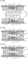
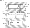
- FIGS. 15A to 15C are longitudinal sectional views to schematically show an exemplary processing flow of the final preforming process.
- FIG. 15A shows a state before pressing
- FIG. 15B a state when the upper die has reached the bottom dead center
- FIG. 15C a state when axial movement is ended.
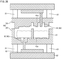
- FIG. 16 is a schematic diagram to show the posture of a second preform and a die clamping direction by upper and lower dies in the final preforming process, the diagram showing the second preform viewed from the axial direction. It is noted that in FIGS. 15A to 15C , although the actual second pin-corresponding part is located in the front or back of the first and third pin-corresponding parts, for convenience sake, the first to third pin-corresponding parts are shown on the same plane.
- FIGS. 15A to 15C show a second preform 24 obtained in the preceding second preforming process, third dies 51 consisting of a pair of upper and lower dies, an upper plate 52, and a lower plate 53.
- the third dies 51 include a third upper die 60 and a third lower die 70.
- the third upper die 60 is supported on the upper plate 52.
- the upper plate 52 moves up and down as a ram (not shown) of a press machine operates.
- the third lower die 70 is supported on the lower plate 53.
- the lower plate 53 is fixed onto a foundation (not shown) of the press machine.
- the third upper die 60 and the third lower die 70 are divided into a plurality of members.
- the members constituting the third upper die 60 and the third lower die 70 are disposed in a line along the axial direction of the second preform 24.
- the third upper die 60 and the third lower die 70 include their respective fixed pin die members 64, 74, a plurality of fixed journal die members 61, 71; a plurality of movable journal die members 62, 72, and a plurality of movable pin die members 63, 73.
- the fixed pin die members 64 and 74 are disposed at a position of the second pin-corresponding part at the middle of the second preform 24.
- the fixed pin die members 64 and 74 are not movable with respect to the upper plate 52 and the lower plate 53, respectively.
- the fixed journal die members 61 and 71 are disposed in the front and back in the axial direction of the fixed pin die members 64 and 74, respectively. That is, the fixed journal die members 61 and 71 are respectively disposed at positions of a weightless-arm-corresponding part connecting to the second pin-corresponding part of the second preform 24, the second and third journal-corresponding parts connecting to the weightless-arm corresponding part, and a web-corresponding part connecting to the journal-corresponding part.
- the fixed journal die members 61 and 71 are not movable with respect to the upper plate 52 and the lower plate 53.
- the movable pin die members 63 and 73 are respectively disposed at positions of the first and third pin-corresponding parts of the second preform 24.
- the movable pin die members 63 and 73 are movable in the axial direction of the second preform 24 and in a direction facing toward the fixed pin die members 64 and 74 (fixed journal die members 61 and 71) on the upper plate 52 and the lower plate 53, respectively.
- the movable pin die members 63 and 73 are not movable in directions other than the axial directions thereof with respect to the upper plate 52 and the lower plate 53.
- the movable journal die members 62 and 72 are respectively disposed at positions of the first and fourth journal-corresponding parts in the second preform 24, and web-corresponding parts connecting to the journal-corresponding parts. It is noted that the movable journal die members 62 and 72 on the fore side are also present at positions of the region to be the front part. The movable journal die members 62 and 72 on the aft side are also present respectively at a position of the region to be the flange part. The movable journal die members 62 and 72 are movable in the axial direction of the second preform 24 and in a direction facing toward the fixed pin die members 64 and 74 (fixed journal die members 61 and 71) on the upper plate 52 and the lower plate 53.
- die-engraved parts (see symbols 61a, 62a, 63a, 64a, 71a, 72a, 73a, and 74a in FIG. 15A ) are formed respectively.
- the die-engraved parts each have a shape reflecting approximate shape of the forged crankshaft (final product).
- the second preform 24 is disposed between the third upper die 60 and the third lower die 70.
- the second preform 24 is disposed in a posture in which the first and third pin-corresponding parts PA1 and PA3 are aligned in a vertical plane. That is, the second preform 24 is disposed in a posture in which the decentering direction of the second pin-corresponding part PA2 corresponds to a horizontal direction. From this state, the third upper die 60 is moved downward.
- the second preform 24 is pressed from a direction perpendicular to the axial direction of the second preform 24 (vertical direction) by the third upper die 60 and the third lower die 70 (see FIG. 15B ).
- the journal-corresponding part, the pin-corresponding part, and the weightless-arm-corresponding part of the second preform 24 are pressed thereby forming approximate shapes of the journal, the pin, and the weightless arm.
- the movable journal die members 62 and 72, and the movable pin die members 63 and 73 are moved in the axial direction of the second preform 24, and in a direction facing toward the fixed pin die members 64 and 74.
- This movement can be realized by, for example, a wedge mechanism or a hydraulic cylinder.
- the web-corresponding part of the second preform 24 is pressed in the axial direction of the second preform 24.
- the thickness of the web-corresponding part decreases to the thickness of the finishing dimension, and approximate shapes of the arm and the weight are formed.
- the pin-corresponding part will not move in the decentering direction. That is, the decentering amounts of the first and third pin-corresponding parts are kept to be equal to ( ⁇ 3)/2 of the decentering amount of the finishing dimension.
- the decentering amount of the second pin-corresponding part is kept to be equal to the decentering amount of the finishing dimension.
- the upper die 60 is moved upward, and the processed second preform 24 (final preform) is taken out.
- the above described first preforming process and the second preforming process make it possible to obtain a second preform without forming flash. As a result, it is possible to improve material yield.
- the production method of the present embodiment it is possible to enhance distribution of volume in the axial direction by the first preforming process and the second preforming process. That is, it is possible to reduce the cross sectional areas of the pin-corresponding part and the journal-corresponding part, and to increase the cross sectional area of the web-corresponding part.
- the second preforming process it is possible to make the width of the web-corresponding part narrowed at the arm-corresponding part, and widened at the weight-corresponding part. That is, it is possible to appropriately distribute volume in the web-corresponding part. For this reason, it is possible, in the following final preforming process, to suppress formation of flash and form an approximate shape of the forged crankshaft. Since the final preform in which an approximate shape of the forged crankshaft is formed is used, it is possible to limit the formation of flash to a minimum in the finish forging process as well. These allow improvement of material yield.
- the thickness of the weightless-arm-corresponding part may be more than that of the finishing dimension.
- the weightless-arm-corresponding part is pressed in the axial direction of the second preform. Therefore, the fixed journal die members 61 and 71 to be used in the final preforming process are changed to the movable journal die members.
- the second die including a web-processing part is used.
- the second preforming process will not be limited to such configuration.
- the material may be flown in from the pin-corresponding part and the journal-corresponding part without pressing the web-corresponding part.
- the volume distribution in the web-corresponding part by the second preforming process can be adjusted by appropriately changing the shape of the arm-processing part depending on the shape of the forged crankshaft (final product).
- the opening width of the arm-processing part may be changed, or an inclined surface may be provided in the arm-processing part. It is noted that providing an inclination surface in the arm-processing part makes it possible to smoothly take out the processed first preform (second preform) from the second dies after the end of pressing.
- the weight of the forged crankshaft (final product) has various shapes. For example, there is a case in which the weight significantly projects in the width direction, and the length of the pin in the decentering direction is small. In such a case, it is effective to change the shape of the weight-processing part in the second preforming process. Examples of changing the shape of the weight-processing part include adjustment of the angle of the inclination surface, and forming the weight-processing part into a curved surface. Moreover, volume may be distributed in the weight-corresponding part by pressing the web-corresponding part from the opening side of the concave web-processing part.
- FIGS. 17A and 17B are cross sectional views to show a case in which the region to be the web (web-corresponding part) is pressed from the opening side of the concave lower-die web-processing part.
- FIG. 17A shows a state before pressing
- FIG. 17B shows a state when pressing is ended.
- the depth of the concave lower-die web-processing part 42c is shallower compared with FIGS. 12A and 12B .
- the web-corresponding part is pushed into the bottom surface side of the concave lower-die web-processing part 42c, and is deformed along the concave lower-die web-processing part 42c.
- the depth of the concave lower-die web-processing part 42c is shallow, in the final stage of pressing by the second dies, the plane-shaped upper-die web-processing part 41c is pushed against the side surface on the opening side of the web-corresponding part.
- the web-corresponding part is pressed from the opening side of the concave lower-die web-processing part 42c so that the width is widened and the length in the decentering direction decreases. As a result, volume is distributed in the weight-corresponding part.
- Light pressing can be realized by, for example, pressing a part of the side surface 23b (see FIG. 12B ) on the opening side of the web-corresponding part. In this case, the material is released to a region that will not come into contact with the die, thus resulting in light pressing.
- the pin-corresponding part is pressed in a state in which a closed section is formed by the upper-die pin-processing part and the lower-die pin-processing part.
- the pin-corresponding part may be pressed without forming a closed section by the pin-processing part.
- FIGS. 18A and 18B are cross sectional views to show a case in which the pin-corresponding part is pressed by the pin-processing part without forming a closed section.
- FIG. 18A shows a state when pressing is started
- FIG. 18B shows a state when pressing is ended.
- the shapes of the upper-die pin-processing part 41b and the lower-die pin-processing part 42b shown in FIGS. 18A and 18B are different from the shapes of the upper-die pin-processing part 41b and the lower-die pin-processing part 42b shown in FIGS. 9A and 9B .
- the upper-die pin-processing part 41b of the second upper die 41 and the lower-die pin-processing part 42b of the second lower die 42 shown in FIGS. 18A and 18B are both concave shaped.
- the depth of the upper-die pin-processing part 41b of the second upper die 41 is more than that of the lower-die pin-processing part 42b of the second lower die 42.
- the upper-die pin-processing part 41b and the lower-die pin-processing part 42b do not abut against the pin-corresponding part around the die-parting plane. Moreover, as the pin-corresponding part is decentered, the material flows out in the axial direction, and the pin-corresponding part is reduced, thus decreasing the cross sectional area. Therefore, it is possible to cause the pin-corresponding part to be decentered and reduced without forming flash.
- the pin-corresponding part When it is desirable to enhance the distribution of volume in the second preforming process, it is preferable to press the pin-corresponding part with a closed section being formed by the first and second pin-processing parts. In view of preventing finning, it is preferable that the pin-corresponding part is partially pressed by the pin-processing part.
- the shape of the journal-processing part shown in FIG. 19 below may be utilized as the shape of the pin-processing part.
- journal-corresponding part is also pressed with a closed section being formed by the upper-die journal-processing part and the lower-die journal-processing part.
- the journal-corresponding part may be pressed without forming a closed section by the journal-processing part.
- the shape of the pin-processing part as shown in FIGS. 18A and 18B may be utilized as the shape of the journal-processing part.
- FIGS. 19A and 19B are cross sectional views to show a case in which the journal-corresponding part is pressed without forming a closed section by the journal-processing part.
- FIG. 19A shows a state when pressing is started
- FIG. 19B shows a state when pressing is ended.
- the shapes of the upper-die journal-processing part 41a and the lower-die journal-processing part 42a shown in FIGS. 19A and 19B are different from those of the upper-die journal-processing part 41a and the lower-die journal-processing part 42a shown in FIGS. 11A and 11B .
- the upper-die journal-processing part 41a of the second upper die 41 has a concave shape that can accommodate the whole of the flat part of the first preform 23 (see a thick line of FIG. 19A ).
- the lower-die journal-processing part 42a on the circular arc of the second lower die 42 is provided in the front end surface of a convex part (see a thick line of FIG. 19A ).
- the upper-die journal-processing part 41a and the lower-die journal-processing part 42a respectively include relief parts 41g and 42g at both ends in the width direction, and the relief parts 41g and 42g spread in the width direction.
- journal-corresponding part When it is desirable to enhance the distribution of volume in the second preforming process, it is preferable to press the journal-corresponding part with a closed section being formed by the upper-die journal-processing part and the lower-die journal-processing part. In view of preventing finning, it is preferable that the journal-corresponding part is partially pressed by the upper-die journal-processing part and the lower-die journal-processing part.
- the first dies 30 are used to form a closed section with the upper-die journal-processing part 31a and the lower-die journal-processing part 32a. Moreover, a closed section is formed with the upper-die pin-processing part 31b and the lower-die pin-processing part 32b. And in that state, the entire circumferences of the journal-corresponding part and the pin-corresponding part of the billet are pressed. This makes it possible to prevent formation of flash.
- the formation of flash may be prevented by partially pressing the journal-corresponding part with the journal-processing part.
- the formation of flash may be prevented by partially pressing the pin-corresponding part with the pin-processing part.
- FIGS. 20A and 20B are cross sectional views to show an exemplary processing flow to perform partial pressing by the journal-processing part in the first preforming process.
- FIG. 20A shows a state before pressing
- FIG. 20B shows a state when pressing is ended.
- the shapes of the upper-die journal-processing part 31a and the lower-die journal-processing part 32a shown in FIGS. 20A and 20B are different from the shapes of the upper-die journal-processing part 31a and the lower-die journal-processing part 32a shown in FIGS. 6A and 6B .
- both of the upper-die journal-processing part 31a and the lower-die journal-processing part 32a have a concave shape and the same depth.
- the pin-processing part of the first dies may adopt a similar configuration to that of the journal-processing part as shown in FIGS. 20A and 20B , and partially press the billet.
- the entire billet is pressed with a closed section being formed with the pin-processing part as shown in FIGS. 5A and 5B .
- the billet is partially pressed by the pin-processing part.
- the cross sectional area Sp2 (mm 2 ) of the pin-corresponding part of the second preform is 0.7 to 1.9 in its ratio (Sp2/Sp0) with respect to the cross sectional area Sp0 (mm 2 ) of the pin of the forged crankshaft (final product).
- the cross sectional area Sp1 (mm 2 ) of the pin-corresponding part of the first preform is preferably 0.9 to 1.9 in its ratio (Sp1/Sp0) with respect to the cross sectional area Sp0 (mm 2 ) of the pin of the forged crankshaft (final product).
- the amount (mm) by which the second pin-corresponding part is to be decentered by the first preforming process is preferably not less than 20% of the decentering amount of the finishing dimension (decentering amount of the pin-corresponding part of the forged crankshaft) E0 (mm). It is more preferably not less than 50% of, and most preferably 100% of, the decentering amount E0 of the finishing dimension. If the decentering amount Ea of the second pin-corresponding part is less than the decentering amount E0 of the finishing dimension, it is necessary to cause the second pin-corresponding part to be further decentered by the finish forging after the final preforming process. For that reason, a flaw may occur. In the above described embodiment, a case in which the decentering amount Ea of the second pin-corresponding part is the same as (100% of) the decentering amount E0 of the finishing dimension is shown.
- the amount by which the first and third pin-corresponding parts are decentered by the second preforming process that is, the decentering amount Eb (mm) of the first and third pin-corresponding parts of the second preform 24 and the final preform 25 are preferably equal to or less than ( ⁇ 3)/2 of the decentering amount E0 (mm) of the finishing dimension.
- the above described embodiment shows a case in which the decentering amount Eb of the first and third pin-corresponding parts is equal to ( ⁇ 3)/2 of the decentering amount E0 of the finishing dimension.
- the decentering amounts Eb of the first and third pin-corresponding parts of the final preform 25 is preferably not less than (1.0 - Dp/2/(( ⁇ 3)/2 ⁇ E0)) in its ratio (Eb/(( ⁇ 3)/2 ⁇ E0)) with respect to the decentering amount E0 of the finishing dimension.
- Dp means a diameter of the pin of the finishing dimension (diameter of the pin of a forged crankshaft).
- the cross sectional area Spb (mm 2 ) of the first and third pin-corresponding parts of the final preform 25 are preferably not less than 0.7 and not more than 1.5 in its ratio ((Spb)/Sp0) with respect to the cross sectional area Sp0 (mm 2 ) of the pin of forged crankshaft, and more preferably not less than 0.75 and not more than 1.1.
- the thickness t1 (mm) of the web-corresponding part of the second preform is not less than 1.1, and more preferably not less than 1.5 in its ratio (t1/t0) with respect to the finish dimension t0 (mm).
- the ratio (t1/t0) is more than 3.5, a bulge deformation area of material surface increases, and the dimensional accuracy of the outer periphery of the arm may deteriorate.
- the ratio (t1/t0) is preferably not more than 3.5.
- the cross sectional area Sw2 (mm 2 ) of the web-corresponding part of the second preform is preferably 0.3 to 0.9 in its ratio (Sw2/Sw0) with respect to the cross sectional area Sw0 (mm 2 ) of the web of the forged crankshaft (final product).
- the cross sectional area Sw1 (mm 2 ) of the web-corresponding part of the first preform is preferably 0.2 to 0.8 in its ratio (Sw1/Sw0) with respect to the cross sectional area Sw0 (mm 2 ) of the web of the forged crankshaft (final product).
- the cross sectional area Sw1 of the web-corresponding part is a total of the cross sectional area of the arm-corresponding part and the cross sectional area of the weight-corresponding part.
- the cross sectional area Sw0 of the web is a total of the cross sectional area of the weight and the cross sectional area of the arm that is integrally included in the weight.
- the cross sectional area Sj2 (mm 2 ) of the journal-corresponding part of the second preform is preferably 1.0 to 1.9 in its ratio (Sj2/Sj0) with respect to the cross sectional area Sj0 (mm 2 ) of the journal of the forged crankshaft (final product).
- the cross sectional area Sj1 (mm 2 ) of the journal-corresponding part of the first preform is preferably 1.2 to 1.9 in its ratio (Sj1/Sj0) with respect to the cross sectional area Sj0 (mm 2 ) of the forged crankshaft (final product).
- the workpiece is a billet 22
- the workpiece may be a stepped starting material.
- FIG. 21 is a schematic diagram to show an exemplary shape of a stepped starting material.
- the pin-corresponding part and the journal-corresponding part are reduced compared with the web-corresponding part. That is, the cross sectional areas of the pin-corresponding part and the journal-corresponding part are less than the cross sectional area of the web-corresponding part.
- the stepped starting material 27 is different from the first preform 23 shown in FIG. 3B in that none of the pin-corresponding parts is decentered.
- the stepped starting material 27 can be formed by using, for example, a reducer roll or a cross roll.
- the stepped starting material is pressed by a pair of first dies as described above.
- the pin-corresponding part is pressed by the pin-processing part to further decrease the cross sectional area of the pin-corresponding part, thus forming a flat part.
- the journal-corresponding part is pressed by the journal-processing part to further decrease the cross sectional area of the journal-corresponding part, thus forming a flat part.
- the second pin-corresponding part is decentered.
- FIGS. 22A to 22C are top views to schematically show the final preforming process in the production method of Embodiment 1.
- FIG. 22A shows a state before pressing
- FIG. 22B a state when the upper die has reached a bottom dead center
- FIG. 22C a state when axial movement is ended.
- FIG. 23 is a schematic diagram to show a posture of the second preform and the die clamping direction of the upper and lower dies in the final preforming process of Embodiment 1, the diagram showing the second preform viewed from the axial direction.
- the production method of Embodiment 1 is different in the form of the third dies used in the final preforming process compared with embodiments shown in FIGS. 3A to 21 .
- FIGS. 22A to 22C show a third lower die 70 of the third dies 51 consisting of the third upper die and the third lower die.
- FIG. 22A shows a profile of the second preform 24 by a dotted line.
- FIGS. 22B and 22C do not show flash.
- the second preform 24 is disposed on the third lower die 70 in a posture in which the first and third pin-corresponding parts PA1 and PA3 are aligned in a vertical plane. For that reason, if the third upper die 60 and the third lower die 70 are die-clamped by downward movement of the third upper die 60 as shown in FIG. 15B , the journal-corresponding part and the pin-corresponding part are pressed along the decentering direction of the first and third pin-corresponding parts PA1 and PA3.
- the second preform 24 is disposed on the third lower die 70 in a position in which the first and third pin-corresponding parts PA1 and PA3 are aligned in a horizontal plane. For that reason, if the third upper die and the third lower die 70 are die-clamped by the downward movement of the third upper die as shown in FIG. 22B , the journal-corresponding part and the pin-corresponding part are pressed from a direction perpendicular to the decentering direction of the first and third pin-corresponding parts PA1 and PA3 (decentering direction of the second pin-corresponding part PA2).
- the posture of the second preform 24 is such that the first and third pin-corresponding parts PA1 and PA3 are aligned in a horizontal plane.
- This posture is the same as that of the final preform in the following finish forging process. For that reason, the position of the flash to be formed in the final preforming process and the position of the flash to be formed in the finish forging process correspond to each other. Therefore, even if flash is formed in the final preforming process, the flash is joined to the flash to be formed in the finish forging process, and is removed in the next flash-trimming process.
- FIGS. 24A to 24C are schematic diagrams to illustrate an exemplary production process of a forged crankshaft of Embodiment 2.
- FIG. 24A shows a first preform
- FIG. 24B a second preform
- FIG. 24C a final preform
- FIGS. 25A to 25C are longitudinal sectional views to schematically show the final preforming process in the production method of Embodiment 2.
- FIG. 25A shows a state before pressing
- FIG. 25B a state when the upper die has reached a bottom dead center
- FIG. 25C a state when axial movement is ended.
- the production method of Embodiment 2 is, compared with the embodiment shown in FIGS.
- the second preform 24 in the final preforming process has such a posture as that the first and third pin-corresponding parts are aligned in a vertical plane.
- the decentering amount of the second pin-corresponding part PA2 of the second preform 24 is less than the decentering amount of the finishing dimension.
- the decentering amounts of the first and third pin-corresponding parts PA1 and PA3 are less than ( ⁇ 3)/2 of the decentering amount of the finishing dimension.
- the first preform 23 is formed such that the decentering amount of the second pin-corresponding part PA2 is such a decentering amount (see FIG. 24A ).
- the second preform 24 is formed such that the decentering amounts of the first and third pin-corresponding parts PA1 and PA3 are such decentering amounts.
- the pin-corresponding parts will not move in the decentering direction. For that reason, as shown in FIGS. 24C , 25B, and 25C , the decentering amount of the pin-corresponding parts of the final preform 25 is not different from the decentering amount of the pin-corresponding parts of the second preform 24. That is, the decentering amount of the second pin-corresponding part of the final preform 25 is less than the decentering amount of the finishing dimension.
- the decentering amount of the first and third pin-corresponding parts PA1 and PA3 are less than ( ⁇ 3)/2 of the decentering amount of the finishing dimension.
- the final preform 25 is disposed on the lower die in a posture in which the first and third pin-corresponding parts are aligned in a horizontal plane. Then, forging is performed by downward movement of the upper die. Therefore, in a stage when the final preform 25 is disposed on the lower die, the second pin-corresponding part of the final preform 25 is floated up from the engraved part for pin, which is formed in the lower die. This is because the decentering amount of the second pin-corresponding part of the final preform 25 is less than the decentering amount of the finishing dimension.
- the first and third pin-corresponding parts of the final preform 25 are deviated from the engraved part for pin formed in the lower die. This is because the decentering amounts of the first and third pin corresponding parts of the final preform 25 are less than ( ⁇ 3)/2 of the decentering amount of the finishing dimension. Even in such a state, the downwardly moving upper die comes into contact with the first and third pin-corresponding parts, and as a result of this, those pin-corresponding parts are pushed into the engraved part for pin of the lower die. Therefore, the first and third pins having the decentering amount of the finishing dimension are obtained.
- the second dies to be used in the final preforming process of Embodiment 2 the second dies having a configuration as that of Embodiment 1 may be adopted.
- FIGS. 26 and 27 are sectional views to show the second dies to be used in the second preforming process of Embodiment 3.
- the second preforming process of Embodiment 3 is different in the configuration of the second dies to be used in the second preforming process compared with the embodiment shown in FIGS. 3A to 21 .
- the first preform 23 is disposed on the second lower die 42 with the second upper die 41 and the second lower die 42 being separated.
- the first pin-corresponding part and the third pin-corresponding part are to be decentered.
- the lower-die pin-processing part 42h which processes the first pin-corresponding part of the first preform 23, projects further than the lower-die journal-processing part 42a. Therefore, when the first preform 23 is disposed on the second lower die 42, the first preform 23 will be inclined. If in this state, the second dies 40 press the first preform 23, the first preform 23 is likely to move in the axial direction since the first preform 23 is inclined.
- the position of the first preform 23, which is to be pressed by the second dies 40 will be deviated from a predetermined position. That is, a situation such as that the pin-processing part of the second dies 40 presses the web-corresponding part of the first preform 23 may occur. For that reason, under-filling or the like may occur in the second preform after pressing.
- the production apparatus of Embodiment 3 includes a fourth lower die 92 in place of the lower-die pin-processing part 42h.
- the fourth lower die 92 can move upward and downward independently from the second dies 40.
- the fourth lower die 92 is disposed at the same height as or at a lower point than the lower-die journal-processing part 42a is. That is, the fourth lower die 92 does not project further than the lower-die journal-processing part 42a. Therefore, even if the first preform 23 is disposed on the second lower die 42 before starting pressing, the first preform 23 is kept approximately horizontal.
- pressing of the first preform 23 by the fourth lower die 92 is started at the same time as the pressing of the first preform 23 by the lower-die journal-processing part 42a, or after starting the pressing of the first preform 23 by the lower-die journal-processing part 42a. Therefore, while the first pin-corresponding part is pressed, the journal-corresponding part of the first preform 23 is pressed by the upper-die journal-processing part 41a and the lower-die journal-processing part 42a. That is, the journal-corresponding part of the first preform 23 is restricted by the upper-die journal-processing part 41a and the lower-die journal-processing part 42a.
- the production apparatus of Embodiment 3 includes fourth dies 90 that consist of a fourth lower die 92 to press the first pin-corresponding part, and a fourth upper die 91 to press the third pin-corresponding part.
- the fourth dies 90 include a control mechanism for causing the pin-processing parts to be independently moved upward and downward.
- the control mechanism is, for example, a die cushion and a hydraulic cylinder.
- the control mechanism is a die cushion 81
- the second lower die 42 is supported by a bolster base 82 via the die cushion 81.
- the die cushion 81 has a cushioning function.
- the fourth lower die 92 is supported by the bolster base 82 via a pin base 83.
- the die cushion 81 is set such that the fourth lower die 92 comes into abutment against the pin-corresponding part of the first preform 23 concurrently, or after, the upper-die journal-processing part 41a and the lower-die journal-processing part 42a abut against the journal-corresponding part of the first preform 23.
- the pin-corresponding part of the first preform 23 will be pressed concurrently with the journal-corresponding part, or after the pressing of the journal-corresponding part is started.
- the hydraulic cylinder 84 can move the fourth lower die 92 upward and downward.
- the fourth lower die 92 is supported by the bolster base 82 via the hydraulic cylinder 84.
- the hydraulic cylinder is activated, and the fourth lower die 92 starts projecting from the second lower die 42.
- the hydraulic cylinder 84 is set such that the fourth lower die 92 abuts against the pin-corresponding parts of the first preform 23 concurrently, or after, the upper-die journal-processing part 41a and the lower-die journal-processing part 42a abut against the journal-corresponding part of the first preform 23.
- the pin-corresponding part of the first preform 23 will be pressed concurrently with the journal-corresponding part, or after the pressing of the journal-corresponding part is started.
- the timing that the fourth lower die 92 projects from the second lower die 42 is appropriately set. That is, the pin-corresponding part of the first preform 23 may be pressed concurrently with the pressing of the journal-corresponding part. The pin-corresponding part may be pressed within a period from the start to the end of pressing of the journal corresponding part. Also the pin-corresponding part may be pressed after the pressing of the journal-corresponding part is completed.
- the present invention can be effectively used for producing a forged crankshaft to be mounted on a 3-cylinder reciprocating engine.
Landscapes
- Engineering & Computer Science (AREA)
- Mechanical Engineering (AREA)
- General Engineering & Computer Science (AREA)
- Ocean & Marine Engineering (AREA)
- Forging (AREA)
- Shafts, Cranks, Connecting Bars, And Related Bearings (AREA)
Applications Claiming Priority (2)
| Application Number | Priority Date | Filing Date | Title |
|---|---|---|---|
| JP2016187835 | 2016-09-27 | ||
| PCT/JP2017/032996 WO2018061765A1 (fr) | 2016-09-27 | 2017-09-13 | Procédé de fabrication de vilebrequin forgé |
Publications (2)
| Publication Number | Publication Date |
|---|---|
| EP3520925A1 true EP3520925A1 (fr) | 2019-08-07 |
| EP3520925A4 EP3520925A4 (fr) | 2020-06-17 |
Family
ID=61762809
Family Applications (1)
| Application Number | Title | Priority Date | Filing Date |
|---|---|---|---|
| EP17855722.9A Withdrawn EP3520925A4 (fr) | 2016-09-27 | 2017-09-13 | Procédé de fabrication de vilebrequin forgé |
Country Status (7)
| Country | Link |
|---|---|
| US (1) | US20190224741A1 (fr) |
| EP (1) | EP3520925A4 (fr) |
| JP (1) | JP6669272B2 (fr) |
| CN (1) | CN109937098A (fr) |
| BR (1) | BR112019004723A2 (fr) |
| MX (1) | MX2019003301A (fr) |
| WO (1) | WO2018061765A1 (fr) |
Families Citing this family (4)
| Publication number | Priority date | Publication date | Assignee | Title |
|---|---|---|---|---|
| WO2019146511A1 (fr) * | 2018-01-25 | 2019-08-01 | 日本製鉄株式会社 | Procédé de fabrication de vilebrequin forgé |
| JP6958724B2 (ja) * | 2018-03-20 | 2021-11-02 | 日本製鉄株式会社 | 鍛造クランク軸の製造方法 |
| JP7485950B2 (ja) | 2020-10-07 | 2024-05-17 | 日本製鉄株式会社 | クランク軸の製造方法 |
| JP7472802B2 (ja) * | 2021-01-20 | 2024-04-23 | トヨタ自動車株式会社 | クランクシャフト |
Family Cites Families (5)
| Publication number | Priority date | Publication date | Assignee | Title |
|---|---|---|---|---|
| US1717513A (en) * | 1929-06-18 | larcher | ||
| JP2000094087A (ja) * | 1998-09-16 | 2000-04-04 | Sumitomo Metal Ind Ltd | クランク軸の製造技術 |
| BR112015013289A2 (pt) * | 2012-12-12 | 2017-07-11 | Nippon Steel & Sumitomo Metal Corp | aparelho para formar esboço para forjamento para eixo de manivela para motor de três cilindros e método para fabricar eixo de manivela forjado para motor de três cilindros com o uso do mesmo |
| JP5972957B2 (ja) * | 2014-12-02 | 2016-08-17 | 本田技研工業株式会社 | クランクシャフトの製造方法 |
| EP3272439B1 (fr) * | 2015-03-18 | 2020-03-11 | Nippon Steel Corporation | Procédé de fabrication de vilebrequin forgé |
-
2017
- 2017-09-13 US US16/329,621 patent/US20190224741A1/en not_active Abandoned
- 2017-09-13 JP JP2018542357A patent/JP6669272B2/ja active Active
- 2017-09-13 CN CN201780059104.1A patent/CN109937098A/zh active Pending
- 2017-09-13 EP EP17855722.9A patent/EP3520925A4/fr not_active Withdrawn
- 2017-09-13 WO PCT/JP2017/032996 patent/WO2018061765A1/fr unknown
- 2017-09-13 BR BR112019004723A patent/BR112019004723A2/pt not_active IP Right Cessation
- 2017-09-13 MX MX2019003301A patent/MX2019003301A/es unknown
Also Published As
| Publication number | Publication date |
|---|---|
| CN109937098A (zh) | 2019-06-25 |
| MX2019003301A (es) | 2019-05-22 |
| EP3520925A4 (fr) | 2020-06-17 |
| WO2018061765A1 (fr) | 2018-04-05 |
| JP6669272B2 (ja) | 2020-03-18 |
| JPWO2018061765A1 (ja) | 2019-06-24 |
| BR112019004723A2 (pt) | 2019-06-18 |
| US20190224741A1 (en) | 2019-07-25 |
Similar Documents
| Publication | Publication Date | Title |
|---|---|---|
| EP3275568B1 (fr) | Procédé de fabrication de vilebrequin forgé | |
| EP3517230A1 (fr) | Procédé de fabrication de vilebrequin forgé | |
| EP3520925A1 (fr) | Procédé de fabrication de vilebrequin forgé | |
| US10456828B2 (en) | Method for producing forged crankshaft | |
| US11045865B2 (en) | Method for producing forged crankshaft | |
| WO2019176508A1 (fr) | Procédé de production de vilebrequin forgé | |
| US11253910B2 (en) | Method for producing forged crankshaft | |
| US10799940B2 (en) | Method for producing forged crankshaft | |
| JP6795094B2 (ja) | 鍛造クランク軸の製造方法 | |
| WO2019146511A1 (fr) | Procédé de fabrication de vilebrequin forgé | |
| WO2019181366A1 (fr) | Procédé de fabrication d'un vilebrequin forgé | |
| US10828693B2 (en) | Apparatus for manufacturing forged crankshaft | |
| JP6935822B2 (ja) | 鍛造クランク軸の製造方法 | |
| JP6933048B2 (ja) | 鍛造クランク軸の製造方法 |
Legal Events
| Date | Code | Title | Description |
|---|---|---|---|
| STAA | Information on the status of an ep patent application or granted ep patent |
Free format text: STATUS: THE INTERNATIONAL PUBLICATION HAS BEEN MADE |
|
| PUAI | Public reference made under article 153(3) epc to a published international application that has entered the european phase |
Free format text: ORIGINAL CODE: 0009012 |
|
| STAA | Information on the status of an ep patent application or granted ep patent |
Free format text: STATUS: REQUEST FOR EXAMINATION WAS MADE |
|
| 17P | Request for examination filed |
Effective date: 20190424 |
|
| AK | Designated contracting states |
Kind code of ref document: A1 Designated state(s): AL AT BE BG CH CY CZ DE DK EE ES FI FR GB GR HR HU IE IS IT LI LT LU LV MC MK MT NL NO PL PT RO RS SE SI SK SM TR |
|
| AX | Request for extension of the european patent |
Extension state: BA ME |
|
| DAV | Request for validation of the european patent (deleted) | ||
| DAX | Request for extension of the european patent (deleted) | ||
| A4 | Supplementary search report drawn up and despatched |
Effective date: 20200519 |
|
| RIC1 | Information provided on ipc code assigned before grant |
Ipc: B21J 13/02 20060101ALI20200513BHEP Ipc: B21J 5/02 20060101ALI20200513BHEP Ipc: B21K 1/08 20060101AFI20200513BHEP Ipc: B21J 5/08 20060101ALI20200513BHEP Ipc: B21J 5/00 20060101ALI20200513BHEP Ipc: F16C 3/08 20060101ALI20200513BHEP |
|
| STAA | Information on the status of an ep patent application or granted ep patent |
Free format text: STATUS: THE APPLICATION IS DEEMED TO BE WITHDRAWN |
|
| 18D | Application deemed to be withdrawn |
Effective date: 20201219 |