EP3520525B1 - Vorrichtung und verfahren zur unterstützung der ultrabreiten bandbreite in new radio der fünften generation (5g) - Google Patents
Vorrichtung und verfahren zur unterstützung der ultrabreiten bandbreite in new radio der fünften generation (5g) Download PDFInfo
- Publication number
- EP3520525B1 EP3520525B1 EP17867454.5A EP17867454A EP3520525B1 EP 3520525 B1 EP3520525 B1 EP 3520525B1 EP 17867454 A EP17867454 A EP 17867454A EP 3520525 B1 EP3520525 B1 EP 3520525B1
- Authority
- EP
- European Patent Office
- Prior art keywords
- band
- bandwidth part
- terminal
- base station
- active
- Prior art date
- Legal status (The legal status is an assumption and is not a legal conclusion. Google has not performed a legal analysis and makes no representation as to the accuracy of the status listed.)
- Active
Links
- 238000000034 method Methods 0.000 title claims description 121
- 238000004891 communication Methods 0.000 claims description 27
- 125000004122 cyclic group Chemical group 0.000 claims description 5
- 238000005259 measurement Methods 0.000 description 144
- 238000010586 diagram Methods 0.000 description 48
- 230000005540 biological transmission Effects 0.000 description 46
- 230000011664 signaling Effects 0.000 description 35
- 238000011084 recovery Methods 0.000 description 33
- 230000006870 function Effects 0.000 description 26
- 238000012544 monitoring process Methods 0.000 description 25
- 230000008859 change Effects 0.000 description 24
- 230000008569 process Effects 0.000 description 23
- 230000004913 activation Effects 0.000 description 18
- 238000005516 engineering process Methods 0.000 description 18
- 230000009849 deactivation Effects 0.000 description 16
- 238000012545 processing Methods 0.000 description 12
- 230000008054 signal transmission Effects 0.000 description 11
- 230000004044 response Effects 0.000 description 10
- 238000000638 solvent extraction Methods 0.000 description 10
- 230000008093 supporting effect Effects 0.000 description 9
- 238000010295 mobile communication Methods 0.000 description 8
- 239000000470 constituent Substances 0.000 description 7
- 230000003213 activating effect Effects 0.000 description 6
- 238000004220 aggregation Methods 0.000 description 6
- 238000004590 computer program Methods 0.000 description 5
- 238000007726 management method Methods 0.000 description 5
- 238000013507 mapping Methods 0.000 description 5
- 238000005192 partition Methods 0.000 description 5
- 230000001960 triggered effect Effects 0.000 description 5
- 239000002699 waste material Substances 0.000 description 5
- 230000006978 adaptation Effects 0.000 description 4
- 230000002776 aggregation Effects 0.000 description 4
- 230000008901 benefit Effects 0.000 description 4
- 239000000872 buffer Substances 0.000 description 4
- 238000004364 calculation method Methods 0.000 description 4
- 230000000694 effects Effects 0.000 description 4
- 230000009471 action Effects 0.000 description 3
- 238000004458 analytical method Methods 0.000 description 3
- VJYFKVYYMZPMAB-UHFFFAOYSA-N ethoprophos Chemical compound CCCSP(=O)(OCC)SCCC VJYFKVYYMZPMAB-UHFFFAOYSA-N 0.000 description 3
- 230000007774 longterm Effects 0.000 description 3
- 238000013468 resource allocation Methods 0.000 description 3
- 230000015556 catabolic process Effects 0.000 description 2
- 238000012937 correction Methods 0.000 description 2
- 238000006731 degradation reaction Methods 0.000 description 2
- 230000003111 delayed effect Effects 0.000 description 2
- 230000006866 deterioration Effects 0.000 description 2
- 238000001914 filtration Methods 0.000 description 2
- 230000000977 initiatory effect Effects 0.000 description 2
- 230000007257 malfunction Effects 0.000 description 2
- 238000012986 modification Methods 0.000 description 2
- 230000004048 modification Effects 0.000 description 2
- 230000009467 reduction Effects 0.000 description 2
- 230000003068 static effect Effects 0.000 description 2
- 238000012546 transfer Methods 0.000 description 2
- 238000012935 Averaging Methods 0.000 description 1
- 101150071746 Pbsn gene Proteins 0.000 description 1
- 102000006463 Talin Human genes 0.000 description 1
- 108010083809 Talin Proteins 0.000 description 1
- 206010000210 abortion Diseases 0.000 description 1
- 231100000176 abortion Toxicity 0.000 description 1
- 230000004931 aggregating effect Effects 0.000 description 1
- 238000013459 approach Methods 0.000 description 1
- 238000003491 array Methods 0.000 description 1
- 230000006399 behavior Effects 0.000 description 1
- 239000000969 carrier Substances 0.000 description 1
- 230000000295 complement effect Effects 0.000 description 1
- 238000010276 construction Methods 0.000 description 1
- 239000013256 coordination polymer Substances 0.000 description 1
- 230000001419 dependent effect Effects 0.000 description 1
- 238000001514 detection method Methods 0.000 description 1
- 230000009977 dual effect Effects 0.000 description 1
- 230000036541 health Effects 0.000 description 1
- 230000001976 improved effect Effects 0.000 description 1
- 238000012423 maintenance Methods 0.000 description 1
- 238000004519 manufacturing process Methods 0.000 description 1
- 229910044991 metal oxide Inorganic materials 0.000 description 1
- 150000004706 metal oxides Chemical class 0.000 description 1
- 230000001151 other effect Effects 0.000 description 1
- 239000004065 semiconductor Substances 0.000 description 1
- 238000003860 storage Methods 0.000 description 1
Images


Classifications
-
- H—ELECTRICITY
- H04—ELECTRIC COMMUNICATION TECHNIQUE
- H04W—WIRELESS COMMUNICATION NETWORKS
- H04W72/00—Local resource management
- H04W72/20—Control channels or signalling for resource management
- H04W72/23—Control channels or signalling for resource management in the downlink direction of a wireless link, i.e. towards a terminal
-
- H—ELECTRICITY
- H04—ELECTRIC COMMUNICATION TECHNIQUE
- H04W—WIRELESS COMMUNICATION NETWORKS
- H04W72/00—Local resource management
- H04W72/04—Wireless resource allocation
- H04W72/044—Wireless resource allocation based on the type of the allocated resource
- H04W72/0453—Resources in frequency domain, e.g. a carrier in FDMA
-
- H—ELECTRICITY
- H04—ELECTRIC COMMUNICATION TECHNIQUE
- H04W—WIRELESS COMMUNICATION NETWORKS
- H04W48/00—Access restriction; Network selection; Access point selection
- H04W48/08—Access restriction or access information delivery, e.g. discovery data delivery
-
- H—ELECTRICITY
- H04—ELECTRIC COMMUNICATION TECHNIQUE
- H04L—TRANSMISSION OF DIGITAL INFORMATION, e.g. TELEGRAPHIC COMMUNICATION
- H04L5/00—Arrangements affording multiple use of the transmission path
- H04L5/003—Arrangements for allocating sub-channels of the transmission path
- H04L5/0044—Arrangements for allocating sub-channels of the transmission path allocation of payload
-
- H—ELECTRICITY
- H04—ELECTRIC COMMUNICATION TECHNIQUE
- H04L—TRANSMISSION OF DIGITAL INFORMATION, e.g. TELEGRAPHIC COMMUNICATION
- H04L5/00—Arrangements affording multiple use of the transmission path
- H04L5/003—Arrangements for allocating sub-channels of the transmission path
- H04L5/0053—Allocation of signaling, i.e. of overhead other than pilot signals
-
- H—ELECTRICITY
- H04—ELECTRIC COMMUNICATION TECHNIQUE
- H04L—TRANSMISSION OF DIGITAL INFORMATION, e.g. TELEGRAPHIC COMMUNICATION
- H04L5/00—Arrangements affording multiple use of the transmission path
- H04L5/0091—Signaling for the administration of the divided path
- H04L5/0092—Indication of how the channel is divided
-
- H—ELECTRICITY
- H04—ELECTRIC COMMUNICATION TECHNIQUE
- H04L—TRANSMISSION OF DIGITAL INFORMATION, e.g. TELEGRAPHIC COMMUNICATION
- H04L5/00—Arrangements affording multiple use of the transmission path
- H04L5/0091—Signaling for the administration of the divided path
- H04L5/0094—Indication of how sub-channels of the path are allocated
-
- H—ELECTRICITY
- H04—ELECTRIC COMMUNICATION TECHNIQUE
- H04W—WIRELESS COMMUNICATION NETWORKS
- H04W72/00—Local resource management
- H04W72/04—Wireless resource allocation
- H04W72/044—Wireless resource allocation based on the type of the allocated resource
- H04W72/0457—Variable allocation of band or rate
-
- H—ELECTRICITY
- H04—ELECTRIC COMMUNICATION TECHNIQUE
- H04W—WIRELESS COMMUNICATION NETWORKS
- H04W72/00—Local resource management
- H04W72/20—Control channels or signalling for resource management
-
- H—ELECTRICITY
- H04—ELECTRIC COMMUNICATION TECHNIQUE
- H04W—WIRELESS COMMUNICATION NETWORKS
- H04W72/00—Local resource management
- H04W72/20—Control channels or signalling for resource management
- H04W72/21—Control channels or signalling for resource management in the uplink direction of a wireless link, i.e. towards the network
-
- H—ELECTRICITY
- H04—ELECTRIC COMMUNICATION TECHNIQUE
- H04W—WIRELESS COMMUNICATION NETWORKS
- H04W72/00—Local resource management
- H04W72/20—Control channels or signalling for resource management
- H04W72/23—Control channels or signalling for resource management in the downlink direction of a wireless link, i.e. towards a terminal
- H04W72/231—Control channels or signalling for resource management in the downlink direction of a wireless link, i.e. towards a terminal the control data signalling from the layers above the physical layer, e.g. RRC or MAC-CE signalling
-
- H—ELECTRICITY
- H04—ELECTRIC COMMUNICATION TECHNIQUE
- H04W—WIRELESS COMMUNICATION NETWORKS
- H04W72/00—Local resource management
- H04W72/20—Control channels or signalling for resource management
- H04W72/23—Control channels or signalling for resource management in the downlink direction of a wireless link, i.e. towards a terminal
- H04W72/232—Control channels or signalling for resource management in the downlink direction of a wireless link, i.e. towards a terminal the control data signalling from the physical layer, e.g. DCI signalling
-
- H—ELECTRICITY
- H04—ELECTRIC COMMUNICATION TECHNIQUE
- H04L—TRANSMISSION OF DIGITAL INFORMATION, e.g. TELEGRAPHIC COMMUNICATION
- H04L27/00—Modulated-carrier systems
- H04L27/26—Systems using multi-frequency codes
- H04L27/2601—Multicarrier modulation systems
- H04L27/2602—Signal structure
-
- H—ELECTRICITY
- H04—ELECTRIC COMMUNICATION TECHNIQUE
- H04L—TRANSMISSION OF DIGITAL INFORMATION, e.g. TELEGRAPHIC COMMUNICATION
- H04L27/00—Modulated-carrier systems
- H04L27/26—Systems using multi-frequency codes
- H04L27/2601—Multicarrier modulation systems
- H04L27/2602—Signal structure
- H04L27/26025—Numerology, i.e. varying one or more of symbol duration, subcarrier spacing, Fourier transform size, sampling rate or down-clocking
-
- H—ELECTRICITY
- H04—ELECTRIC COMMUNICATION TECHNIQUE
- H04L—TRANSMISSION OF DIGITAL INFORMATION, e.g. TELEGRAPHIC COMMUNICATION
- H04L5/00—Arrangements affording multiple use of the transmission path
- H04L5/0001—Arrangements for dividing the transmission path
- H04L5/0003—Two-dimensional division
- H04L5/0005—Time-frequency
- H04L5/0007—Time-frequency the frequencies being orthogonal, e.g. OFDM(A), DMT
- H04L5/001—Time-frequency the frequencies being orthogonal, e.g. OFDM(A), DMT the frequencies being arranged in component carriers
-
- H—ELECTRICITY
- H04—ELECTRIC COMMUNICATION TECHNIQUE
- H04L—TRANSMISSION OF DIGITAL INFORMATION, e.g. TELEGRAPHIC COMMUNICATION
- H04L5/00—Arrangements affording multiple use of the transmission path
- H04L5/003—Arrangements for allocating sub-channels of the transmission path
- H04L5/0048—Allocation of pilot signals, i.e. of signals known to the receiver
- H04L5/005—Allocation of pilot signals, i.e. of signals known to the receiver of common pilots, i.e. pilots destined for multiple users or terminals
-
- H—ELECTRICITY
- H04—ELECTRIC COMMUNICATION TECHNIQUE
- H04L—TRANSMISSION OF DIGITAL INFORMATION, e.g. TELEGRAPHIC COMMUNICATION
- H04L5/00—Arrangements affording multiple use of the transmission path
- H04L5/0091—Signaling for the administration of the divided path
- H04L5/0096—Indication of changes in allocation
- H04L5/0098—Signalling of the activation or deactivation of component carriers, subcarriers or frequency bands
-
- Y—GENERAL TAGGING OF NEW TECHNOLOGICAL DEVELOPMENTS; GENERAL TAGGING OF CROSS-SECTIONAL TECHNOLOGIES SPANNING OVER SEVERAL SECTIONS OF THE IPC; TECHNICAL SUBJECTS COVERED BY FORMER USPC CROSS-REFERENCE ART COLLECTIONS [XRACs] AND DIGESTS
- Y02—TECHNOLOGIES OR APPLICATIONS FOR MITIGATION OR ADAPTATION AGAINST CLIMATE CHANGE
- Y02D—CLIMATE CHANGE MITIGATION TECHNOLOGIES IN INFORMATION AND COMMUNICATION TECHNOLOGIES [ICT], I.E. INFORMATION AND COMMUNICATION TECHNOLOGIES AIMING AT THE REDUCTION OF THEIR OWN ENERGY USE
- Y02D30/00—Reducing energy consumption in communication networks
- Y02D30/70—Reducing energy consumption in communication networks in wireless communication networks
Definitions
- the present disclosure relates to a physical layer (PHY) / medium access control (MAC) layer operation of a terminal and a base station in a mobile communication system. More specifically, the present disclosure relates to a method and an apparatus capable of efficiently using a bandwidth and flexibly and dynamically supporting a bandwidth change because signal transmission / reception may be achieved only in a limited bandwidth due to a limited operating bandwidth and power consumption of a terminal when a base station tries to transmit / receive an ultra-wide bandwidth signal to / from a single carrier.
- PHY physical layer
- MAC medium access control
- the 5G communication system or the pre-5G communication system is called a beyond 4G network communication system or a post long term evolution (LTE) system.
- LTE post long term evolution
- the 5G communication system is considered to be implemented in a very high frequency (mmWave) band (e.g., like 60 GHz band).
- the 5G communication system To relieve a path loss of a radio wave and increase a transfer distance of the radio wave in the very high frequency band, in the 5G communication system, beamforming, massive MIMO, full dimensional MIMO (FD-MIMO), array antenna, analog beam-forming, and large scale antenna technologies have been discussed. Further, to improve a network of the system, in the 5G communication system, technologies, such as an evolved small cell, an advanced small cell, a cloud radio access network (cloud RAN), an ultra-dense network, a device to device communication (D2D), a wireless backhaul, a moving network, cooperative communication, coordinated multi-points (CoMP), and reception interference cancellation have been developed.
- cloud RAN cloud radio access network
- D2D device to device communication
- CoMP coordinated multi-points
- hybrid FSK and QAM modulation FQAM
- SWSC sliding window superposition coding
- ACM advanced coding modulation
- FBMC filter bank multi carrier
- NOMA non orthogonal multiple access
- SCMA sparse code multiple access
- the Internet is evolved from a human-centered connection network through which a human being generates and consumes information to the internet of things (IoT) network that transmits / receives information between distributed components, such as things and processes the information.
- IoT internet of things
- IoE internet of everything
- technology elements such as a sensing technology, wired and wireless communication and network infrastructure, a service interface technology, and a security technology, have been required.
- technologies such as a sensor network, machine to machine (M2M), and machine type communication (MTC) for connecting between things have been researched.
- an intelligent internet technology (IT) service that creates a new value in human life by collecting and analyzing data generated in the connected things may be provided.
- the IoT may apply for fields, such as a smart home, a smart building, a smart city, a smart car or a connected car, a smart grid, health care, smart appliances, and an advanced healthcare service, by fusing and combining the existing information technology (IT) with various industries.
- the 5G communication technologies such as the sensor network, the M2M, and the MTC
- the 5G communication technologies have been implemented by techniques, such as the beamforming, the MIMO, and the array antenna.
- the application of the cloud radio access network (cloud RAN) as the big data processing technology described above may also be considered as an example of the fusing of the 5G communication technology with the IoT technology.
- the existing LTE system has adopted a multi-carrier scheme in which multiple component carriers (CCs), such as carrier aggregation (CA) and dual connectivity (DC) are bundled and operated to support a wideband. Aggregating up to 32 CCs may support a bandwidth of 640 MHz on a 20 MHz CC basis.
- CCs component carriers
- CA carrier aggregation
- DC dual connectivity
- a scheme, such as LTE CA is applied to support ultra-wide bandwidth, for example, 1 GHz in a 5G new radio (NR) system
- the number of combinations of CCs to be used by the terminal is increased exponentially, a size of a UE-capability report is increased, and the 5G NR system cannot but operate only within the limited number of combinations of CCs.
- the CA / DC shows higher flexibility in resource usage than single carrier. This is because an extension bandwidth may be changed by addition / release of a secondary cell (SCell), and the transmission / reception of resources to another CC may be scheduled by cross-carrier scheduling.
- SCell secondary cell
- HUAWEI ET AL "Support of flexible bandwidth", (3GPP DRAFT; R1-1608841, 3RD GENERATION PARTNERSHIP PROJECT (3GPP), MOBILE COMPETENCE CENTRE; 650, ROUTE DES LUCIOLES; F-06921, SOPHIA-ANTIPOLIS CEDEX; FRANCE, vol. RAN WG1, no. Portugal; 20161010-20161014 9 October 2016 , discloses the support of flexible bandwidth in NR, and mainly focusses on the analysis of bandwidth flexibility in NR from network and UE perspective respectively.
- US 2015/365209 A1 discloses a method for performing resource allocation in a wireless communication system, performed by a user equipment (UE), the method comprising receiving a configuration of an entire system bandwidth including a predefined system bandwidth and a carrier segment in which is allocated in not available region for the predefined system bandwidth; checking an indication to indicate whether the entire system bandwidth is available or not for the UE, and information for the entire system bandwidth in the configuration; and receiving a reference signal and a control signal at subframes determined based on the indication and the information.
- UE user equipment
- INTERDIGITAL COMMUNICATIONS "UE Support for Multiple Numerologies for NR", 3GPP DRAFT; R1-1610022, 3RD GENERATION PARTNERSHIP PROJECT (3GPP), MOBILE COMPETENCE CENTRE; 650, ROUTE DES LUCIOLES; F-06921 SOPHIA-ANTIPOLIS CEDEX; FRANCE, vol. RAN WG1, no. Portugal; 20161010-20161014 1 October 2016 (2016-10-01 ) discloses about the configuration of multiple numerologies on a carrier. It further discusses the effect of such support on UE behavior. It also discusses how based on a UE's need it may be required to transmit and/or receive multiple numerologies simultaneously.
- an aspect of the present disclosure is to provide a limited signal transmission / reception procedure of a base station and a terminal based on power consumption of the terminal in a single carrier and a controlling method capable of dynamically and flexibly using the whole bandwidth of a system.
- a terminal can perform the scheduling, the modulation and coding scheme (MCS), the channel state indication (CSI) report, the measurement, and the like within configured partial bands, and the reduction in scheduling and handover performance for the whole bandwidth may be minimized.
- MCS modulation and coding scheme
- CSI channel state indication
- constitutional parts shown in the embodiments of the present disclosure are independently shown so as to represent different characteristic functions. Thus, it does not mean that each constitutional part is constituted in a constitutional unit of separated hardware or one software.
- the respective constitutional parts are included by being arranged as each constitutional part and at least two constitutional parts of the respective constitutional parts may form one constitutional part or one constitutional part is divided into a plurality of constitutional parts to perform functions.
- An integrated embodiments and a separated embodiment of the respective constitutional parts are also included in the scope of the present disclosure unless departing from the nature of the present disclosure.
- constituents may not be indispensable constituents performing essential functions of the present disclosure but be selective constituents improving only performance thereof.
- the present disclosure may be implemented by including only the indispensable constitutional parts for implementing the essence of the present disclosure except the constituents used in improving performance.
- the structure including only the indispensable constituents except the selective constituents used in improving only performance is also included in the scope of the present disclosure.
- each block of processing flow charts and combinations of the flow charts may be performed by computer program instructions. Since these computer program instructions may be mounted in processors for a general computer, a special computer, or other programmable data processing apparatuses, these instructions executed by the processors for the computer or the other programmable data processing apparatuses create means performing functions described in block(s) of the flow charts. Since these computer program instructions may also be stored in a computer usable or computer readable memory of a computer or other programmable data processing apparatuses in order to implement the functions in a specific scheme, the computer program instructions stored in the computer usable or computer readable memory may also produce manufacturing articles including instruction means performing the functions described in block(s) of the flow charts.
- the instructions performing a series of operations on the computer or the other programmable data processing apparatuses to create processes executed by the computer to thereby execute the computer or the other programmable data processing apparatuses may also provide operations for performing the functions described in block(s) of the flow charts.
- the term '-unit' used in the present embodiment means software or hardware components, such as field programmable gate array (FPGA) and application-specific integrated circuit (ASIC) and the ' ⁇ unit' performs any roles.
- the ' ⁇ unit' may be configured to be in a storage medium that may be addressed and may also be configured to reproduce one or more processor.
- the ' ⁇ unit' includes components, such as software components, object oriented software components, class components, and task components and processors, functions, attributes, procedures, subroutines, segments of program code, drivers, firmware, microcode, circuit, data, database, data structures, tables, arrays, and variables.
- the functions provided in the components and the ' ⁇ units' may be combined with a smaller number of components and the ' ⁇ units' or may be further separated into additional components and ' ⁇ units'.
- the components and the ' ⁇ units' may also be implemented to reproduce one or more central processing units (CPUs) within a device or a security multimedia card.
- CPUs central processing units
- the present disclosure proposes a control and configuration method for ultra-wideband transmission / reception in a fifth generation (5G) mobile communication system.
- a method for scheduling, handover, and radio link failure (RLF) recovery in ultra-wide bandwidth may be considered.
- various services or slices
- eMBB enhanced Mobile Broadband
- URLLC ultra reliable and low latency communication
- eMTC enhanced machine type communication
- VoIP voice over internet protocol
- BE best effort
- LTE long term evolution
- various numerologies are expected to be supported in the 5G mobile communication system.
- This may specifically include subcarrier spacing, and the like, which may directly affect a transmission time interval (TTI).
- TTI transmission time interval
- various numerologies are expected to be supported in the 5G mobile communication system. This is one of the characteristics of the 5G mobile communication system which very differ from those of the currently standardized LTE which supports only one kind of TTI (for example, 1 ms). If the 5G mobile communication system supports a TTI (for example, 0.1 ms, and the like) which is much shorter than the 1 ms TTI of LTE, it is expected to be very helpful in supporting the URLLC, and the like, which requires a short latency.
- the numerology may be used as the term serving as the subcarrier spacing, a subframe length, a symbol / sequence length, cyclic prefix, and the like.
- the numerology may be a cause which makes terminals to have different bandwidths (BWs).
- the base station may be represented by various abbreviations, such as next generation (gNB), evolved node B (eNB), node B (NB), and base station (BS).
- the terminal may be represented by various abbreviations, such as UE, MS, STA, and the like.
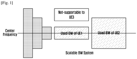
- FIG. 1 is a diagram illustrating a scalable bandwidth (BW) system of LTE according to various embodiments of the present disclosure.
- the LTE system introduces a concept of a scalable BW to support various BWs and may support terminals having various BWs (e.g., 5/10/20 MHz, and the like) having the same center frequency.
- the LTE base station may appropriately configure a control channel and transmit a control signal so that both of the UE 1 and UE 2 can receive the control signal.
- this method may limit resources available for a terminal supporting a relatively small bandwidth when the entire capable bandwidth of the base station is very large, that is, in an ultra-wide bandwidth. For example, if the UE 3 is operated at an edge of the used bandwidth of the base station, the UE 3 may not separately receive the control signal of the base station.
- the terminal has to be able to transmit and receive important control signals so that the terminal maintains the connection with the base station even in a bandwidth not supported by the existing scalable BW system.
- the important control signal may be transmitted through a primary cell (PCell) by a signaling radio bearer (SRB) in the case of the LTE.
- PCell primary cell
- SRB signaling radio bearer
- a control signal for scheduling and hybrid automatic repeat request (HARQ) procedure in the PCell itself and a secondary cell (SCell) may be transmitted / received.
- Both of the PCell and the SCell of the LTE may be viewed as one independent cell.
- separate medium access control (MAC) entity and link adaptation according thereto and HARQ entity are required for each cell.
- MAC medium access control
- link adaptation link adaptation according thereto and HARQ entity are required for each cell.
- functions of the PCell for connection / connection establishment / maintenance and data transmission / reception of the terminal should be basically provided.
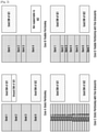
- FIG. 2 is a diagram illustrating various band partitioning schemes according to various embodiments of the present disclosure.
- the terminal enables transmission / reception at once only in some of the whole bandwidth because of limited implementation and complexity.
- the terminal In order for the terminal to be operated in a bandwidth larger than a maximum capable BW of the terminal, the terminal cannot but be operated by being temporally partitioned.
- the base station may configure the whole bandwidth by partitioning the whole bandwidth into several bands having an appropriate size and instruct the terminal to perform various MAC functions (e.g., scheduling, measurement, link adaptation, modulation and coding (MCS) scheme, HARQ, and the like) in a specific band.
- the terminal may determine and receive the structure of the control channel and the reference signal (RS).
- RS reference signal
- case A illustrates static partitioning.
- the base station may partition the whole bandwidth into a plurality of bands having the same size. For example, the whole bandwidth may be partitioned into four bands having the same size.
- the terminal 1 (UE 1) may support a bandwidth larger than band 1.
- the base station configures a band to be a fixed size, the terminal 1 may be operated with the base station even in some of the entire capable bandwidth, not in the entire capable bandwidth. For example, although the terminal 1 may be operated with the base station in the band 1, since the remaining bandwidths larger than the bandwidth of the band 1 in the capable bandwidth of the terminal 1 is smaller than that of the band 2, the terminal 1 cannot be operated with the base station in the remaining bandwidths.
- Case B illustrates flexible partitioning.
- the base station may partition the whole bandwidth into a plurality of bands having various sizes.
- the capable bandwidth of the terminal 1 is equal to that of the band 1, the terminal 1 may be operated with the base station in the entire capable bandwidth.
- the terminal 2 UE 2
- the maximum capable bandwidth is smaller than that of band 4 configured by the base station, the operation of the terminal 2 cannot be supported.
- the base station may partition the whole bandwidth by minimizing the unit of the band.
- the bandwidth to be used by the terminal may be represented by a bundle of small bands, it is possible to support terminals having various sizes of bandwidths.
- the terminal 1 may be operated with the base station through a bundle of bands 1 to 6, and the terminal 2 may communicate with the base station through a bundle of bands 13 to 16.
- Case C too many bands may increase a load during management. Therefore, as in Case D, a method of freely configuring a band size may be useful (flexible partitioning with fine granularity).
- the method is a method of partitioning a unit of a band into small pieces while varying the size of the band.
- Case B the terminal 2 cannot be supported, but in Case D, the terminal 2 may be operated with the base station through a bundle of bands 6 and 7.
- the base station in order to address the issue of the method in which the base station partitions the whole bandwidth into bands and configures the bands to be in terminals from the cases A to D, the base station configures bands having different sizes for each terminal.
- a method of representing a band configured in a terminal by a combination of sub-bands having the same size will be described.
- the independent scheduling, the link adaptation, the MCS, the HARQ procedure, or the like are not performed in the partitioned sub-band, like the existing CA, but from the viewpoint of the terminal, the method for performing one scheduling, the link adaptation, the MCS, the HARQ procedure, or the like in the configured band will be described.
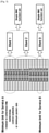
- FIG. 3 is a diagram of a band partitioning structure according to an embodiment of the present disclosure.
- a structure of a physical layer control channel should be designed to be scalable in one or a plurality of sub-bands in one band. This means that it is possible to support a terminal having a band that may be represented by at least a multiple of sub-bands in the band. However, a terminal having a band larger than a configured band does not have to be supported in the band.
- the size of the band which is a bundle of sub-bands, may be determined by at least one of channel characteristics, numerology, a control sub-band size, and a minimum packet size between the terminal and the base station.
- the terminal may perform one MAC function set (e.g., scheduling, MCS, HARQ, and the like) for one service.
- the band may mean some of the whole bandwidth, which may be referred to as a bandwidth part (BWP), some bandwidths, or the like.
- BWP bandwidth part
- the base station may configure a sub-band in a terminal by one method of system information (SI) or a radio resource control (RRC) connection establishment procedure.
- SI system information
- RRC radio resource control
- the sub-band configuration may be represented by a resource element (RE), that is, one resource unit consisting of a subcarrier spacing and a symbol, time of RE, and the number of frequency domains.
- the time domain can be represented by a symbol number
- the frequency domain can be represented by a subcarrier spacing number.
- the RE may vary according to a type of numerology. If the base station partitions the resource into a plurality of different numerology regions, the length of the symbol and the subcarrier spacing that configures up the RE in each region may be changed.
- one sub-band may be represented by k REs.
- the value k may be a value (pre) set to one value regardless of the numerology region.
- the base station may set values for each numerology region in the terminal by an additional SI or RRC message.
- the sub-band configuration may be represented by the number of physical resource blocks (PRB) and a frequency location (e.g., a position of a center frequency).
- PRB physical resource blocks
- the base station may configure an operating bandwidth of the terminal, that is, a band based on a sub-band for an IDLE mode terminal or a connected mode terminal.
- a band may be configured in the terminal by a sub-band index and the number of sub-bands.
- the band may have different sizes depending on the configuration.
- the band may be configured in the terminal by the SI or RRC message, together with the sub-band configuration or may be configured in the UE by the SI or RRC message separately from the sub-band configuration. Therefore, according to the embodiment of the present disclosure, the sub-band may be configured by SI and the band can be configured by the RRC message.
- the network may inform the terminal of numerology information to configure the band by the SI or RRC message.
- the terminal may accurately identify a structure of one band by combining the numerology information set for each band and the sub-band information for each numerology. If only one of the band and the sub-band is configured, in order to obtain information on the other, the terminal may obtain the information from the information on the configured band or sub-band according to a predetermined rule.
- each sub-band is a unit that is differentiated in terms of the network, but the band may be configured for each terminal, and the region may also overlap in terms of the network. Further, the position and number of control sub-bands may be set in the configured band.
- a control sub-band may be referred to as a control resource set, a control sub-resource, a control channel resource, or the like.
- the control sub-band indicates a resource for receiving DCI in a control channel that the terminal monitors.
- at least one common control sub-band and control sub-bands for each terminal may be configured for one band.
- a DL downlink (DL) assignment message and / or an UL (uplink) grant message for general scheduling for each terminal may be indicated as control sub-bands for each terminal. If other bands are not indicated in the DL assignment message and / or the UL grant message, the terminal may accept the DL assignment message and / or the UL grant message indicated by the control sub-bands for each terminal as a transmission / reception indication for the band in which the control sub-bands for each terminal is configured. For example, there may be a one-to-one relationship between the control sub-bands for each terminal and bands.
- the resource information for data transmission is indicated by a resource block (RB) unit.
- a start (or end) point of a first RB matches a start (or end) point of a band or may be a location which may be directly calculated from the band and sub-band configuration information.
- the base station may inform the terminal of resources allocated to the start points and the number of RBs.
- the base station needs to inform the terminal of band index information (band index, band ID, and the like) indicating the band in addition to the RB information.
- the base station may transmit the configuration information to the terminal, including the index information per-beam to configure one or more band in the terminal.
- the RB information is logically partitioned and the real physical resource may be mapped to a continuous or discontinuous resource RE.
- the band index information may be separately assigned to the DL band or the UL band, and may be assigned in common regardless of the DL / UL band.
- the base station may include the numerology information in the band setting information in order to instruct the terminal to configure the band.
- the terminal may calculate the RE structure from the numerology information, and may identify the control sub-band and the resource information for data transmission according to the calculated RE structure.
- the base station can separately set the numerology applied to the RE structure for constructing the sub-band in the terminal using the SI or RRC message.
- the RE structure for configuring the sub-band and the RE structure for configuring the band may be different.
- the DL band and the UL band may have different configuration information, such as the frequency location and the numerology, and are linked to the DL operation and the UL operation of the terminal, respectively, such that the DL band and the UL band may be configured separately.
- the terminal may perform an operation for the DL control and data reception from the information of the band configured in the DL band, and may perform an operation for the UL control and data transmission from the information of the band configured in the UL band.
- the base station may configure the band and the control sub-bands for the common / terminal in the terminal from the base station during the switching from the idle mode to the connected mode.
- the base station may configure the band information or the control sub-band connected to the band in the terminal through a random access response (RAR) or a message 4 (Msg4) (e.g., RRC connection complete) during a random access procedure.
- RAR random access response
- Msg4 message 4
- the terminal may determine the location of the sub-band and the band used in the connected mode based on at least one of a synchronization signal (SS) bandwidth, an idle mode bandwidth, and a physical random access channel (PRACH) bandwidth according to a predetermined rules.
- SS synchronization signal
- PRACH physical random access channel
- the terminal may transmit UE capability information to the network during a procedure of connecting to the network (e.g., random access or RRC (re)configuration).
- the UE capability information may include at least one of the following information: The number of radio frequencies (RFs), a maximum operating bandwidth of one RF, a maximum operating bandwidth of the terminal, RF retuning latency of the terminal at which the center frequency is maintained, and RF retuning latency of the terminal at which the center frequency is switched, a type of operable numerology, or the like.
- the base station may inform the terminal of the location and the range of the band (e.g., start, size or center frequency and bandwidth, and the like) by the multiple of the basic unit (e.g., RB or sub-band).
- the location and the range of the band are a part of one carrier in which the network system operates, and therefore may be set by a frequency offset and a bandwidth of a bandwidth respect to a center frequency of the entire carrier bandwidth according to the embodiment.
- the location and the range of the band according to the embodiment may be set by the frequency offset and the bandwidth of the band with respect to the center frequency at which a synchronization signal detected by the terminal is located.
- the center frequency of the carrier bandwidth that the terminal understands may be the center frequency of the synchronization signal detected by the terminal, or may be identical to the center frequency information of the carrier indicated by the SI connected to the synchronization signal detected by the terminal or the center frequency information of the carrier at which the terminal is instructed from the base station during the RRC connection establishment procedure.
- the terminal may understand the band range as a system bandwidth. Therefore, even if bands in different ranges are allocated, the terminal and the base station should be designed to be able to be received according to the same reception rule. For example, the reference signal RS or the location of the control channel that the base station transmits should be able to be transmitted and received based on the start and size of the band configured in the terminal. In addition, the CSI report or the location of the HARQ feedback that the terminal transmits should also be able to be transmitted and received based on the start and size of the band configured in the terminal. Meanwhile, when a plurality of bands are configured in the terminal, the base station may additionally configure, in the terminal, whether the HARQ process is shared in the plurality of bands or whether the HARQ process is separated for each band.
- the band that is basically monitored by the terminal is referred to as a primary band (p-band).
- a primary band In a resource area other than the p-band, the monitoring may not be performed in a resource area other than the p-band before a separate control / configuration is performed in the p-band.
- a secondary band (s-band) is selectively operated according to the configuration through the p-band, and the p-band and the s-band may be called a first RF band and a second RF band according to the embodiment.
- the p-band may be activated to an active state through an RRC message or an MAC CE among at least one configured band candidate.
- the s-band may be activated to an active state through the RRC message, the MAC CE, or the DCI among at least one configured band candidate.
- the base station may deactivate one or more bands from an active state to an inactive state by transmitting or a deactivation signal / message to the terminal through the RRC message, the MAC CE, or the DCI.
- an active band and the p-band may be interchangeably used in a similar meaning.
- the active band and the p-band may be different. For example, when the p-band is configured, the DL band and the UL band may be combined with each other.
- the p-band is a basic active band in one cell, but all active bands are not the p-band.
- the p-band may not be deactivated except for a separate band switch procedure.
- the frequency locations of the DL band and the UL band may be the same, so that the DL band and the UL band may be configured as a bundle.
- the p-band configuration may include at least one DL band and at least one UL band so that the base station may instruct the terminal. If the terminal reports the UE capability report including the RF information to the base station, the base station may set a p-band for each different RFs of the terminal.
- the base station may additionally set the p-band state together with one or more band configuration by the RRC message.
- the terminal may be configured to receive at least one of 1) RRC message, 2) MAC CE, 3) L2 common signaling, 4) L1 common signaling, and 5) UE dedicated signaling only in the p-band.
- the terminal may be configured to operate at least one of other functions, for example, 1) radio link monitoring (RLM), 2) discontinuous reception (DRX), 3) measurement, 4) synchronization, 5) paging, and 6) random access only in the p-band.
- the base station may configure the RLM, the measurement, and the DRX functions in the terminal so that the terminal may be operated not only in the p-band but also in the s-band.
- the terminal may operate the active band only in one band at a time, then the terminal instructs a band switch or cross-band scheduling to another s-band (e.g., band # 1) in the p-band (e.g., band # 0), the terminal needs to deactivate the p-band (band # 0) for a while and activate another s-band (band # 1).
- the operation of the terminal may be restricted in the switched s-band (band # 1) according to the configuration for each message or function described above.
- both the p-band and the s-band may be the active band, but the operations of the terminal for each band may be different.
- the terminal operation may be different when the RLM and the RLF function are applied only to the p-band and when the RLM and the RLF function are applied to both of the p-band and the s-band. If the RLM / RLF is applied only to the p-band, the terminal may not perform the RLM if it does not receive the signal of the base station when being operated by activating the s-band, or may not trigger the RLF event even if it performs the RLM. In this case, this may be replaced by a procedure of falling back from the s-band to the p-band, which will be described below.
- the terminal may trigger RLM and RLF events for the active band among all bands configured to be RLM / RLF.
- the RLM result in the s-band may be preset or reflected to RLM / RLF event determination for the serving cell according to the setting of the base station.
- the terminal may start a fallback timer that is separately set as it satisfies a condition for determining a reception error of a base station signal due to deterioration of channel quality in the s-band. If the condition that the base station signal is received again is satisfied, the terminal may stop, reset, or restart the fallback timer. If the error condition of base station signal reception continues to be satisfied and thus the fallback timer expires, the terminal may switch the RF to the p-band.
- the terminal may monitor the effective control channel according to the p-band or commonly set control channel location and DRX setting. If the condition for successfully receiving the feedback or UL signal of the terminal in the s-band is not satisfied for a predetermined time or until a timer expires, the base station may be operated to a control signal to the terminal in the effective control channel according to the DRX setting and the location of the control channel configured in the terminal in the p-band.
- the base station and the terminal may perform the p-band recovery operation as the performance of the terminal in the p-band is reduced, in which the p-band recovery and the fallback operation may be classified as the following Table 1.
- Table 1 p-band recovery fallback Band switch From old p-band to new p-band From s-band to p-band Time scale
- Tens of ms Several ms Problem determination condition Al least one of the existing RLF conditions Control channel inactivity
- the activation / deactivation MAC control element may be a new MAC CE for the band.
- the activation / deactivation MAC CE may reuse the MAC CE for the existing SCell.
- the network may activate and deactivate the configured SBands.
- the network activates and deactivates the SBand(s) by:
- the MAC entity shall for each NR-UNIT and for each configured SBand:
- the terminal may monitor only at least one of one or more configured bands according to the RF conditions, and may view one or more of them. Therefore, it may be advantageous in terms of scalability that the band indication of the base station is commonly applied to the terminals in different RF conditions. However, the base station should know other RF conditions of the terminal in advance through the capability report of the terminal. Otherwise, there is a possibility of malfunction if the base station cannot know whether Band # 1 is deactivated due to the RF restriction of the terminal when the base station issues an activation indication for Band #2 to any terminal in Band#1.
- a terminal operated in a single active band receives a band activation indication of a base station
- the previous band is deactivated while switched to the indicated band (i.e., activating the indicated band).
- the indicated band may be activated and maintain a band which is in use by being activated in advance.
- the base station should be able to set the maximum number of active bands of the terminal and to clearly indicate the deactivation of the bands.
- the terminal may be set in advance whether to operate the active band according to any of the following two methods or set by the base station / network.
- the operation may be identically applied to a case where a band switch / activation is performed in conjunction with a cross-band scheduling indication in addition to a separate band activation indication of the base station.
- the terminal may change the RF retuning time according to the relationship between the active band switch condition and the switching band.
- the base station may set in the terminal, for example, a time required to switch to another band with respect to one band (for example, p-band) based on the capability report by the RRC message. If the terminal does not comply with the setting, the terminal may perform a reject per band.
- the terminal When the base station instructs the terminal to perform the band activation by the DCI, the terminal 1) may monitor the fastest valid control channel in the band activated after the switching time axis on the band ID included in the DCI, based on the switching latency from the DCI receiving time (e.g., subframe / slot / minislot, and the like) preset by the RRC message to the switching complete or 2) monitor the fastest valid control channel after the time determined depending on a k value, by specifying in the DCI the switching latency k from the DCI receiving time (e.g., subframe / slot / minislot, and the like) to the switching complete, along with the band ID.
- the DCI receiving time e.g., subframe / slot / minislot, and the like
- the terminal may be operated by at least one of 1) monitoring the fastest control channel valid in the band activated after the switching latency from the HARQ acknowledgment (ACK) success time (e.g., subframe / slot, minislot, and the like) for the MAC CE reception to the switching complete based on the band ID included in the MAC CE, based on the switching time preset by the RRC message, 2) monitoring the fastest control channel valid in the band activated after the switching latency from the time (e.g., subframe / slot / minislot, and the like) when the indication drops to the PHY again by analyzing the MAC CE and allowing the MAC to determine the band switch based on the band ID included in the MAC CE, based on the switching latency preset by the RRC message, 3) monitor the fastest valid control channel in the band activated after the switching latency from the time when the MAC CE reception success time (e.g., subframe / slot / minislot, and the like)
- the base station can separately instruct the terminal to perform the band configuration and the CSI-RS configuration.
- the base station may instruct the terminal to report the measurement result according to at least one of the following methods.
- the terminal may measure the CSI-RS indicated by the base station and report the result according to the CSI-RS report setting interlocked with the CSI-RS resource.
- the base station can separately instruct the terminal to perform the band configuration and the CSI-RS configuration.
- the base station may instruct the terminal to report the measurement result according to at least one of the following methods. 1) The terminal may measure the CSI-RS indicated by the base station and report the result to the base station according to the CSI-RS report setting interlocked with the CSI-RS resource. 2) The base station transmits the band index to the terminal to indicate the band switch, and the terminal may report to the base station after measuring the CSI-RS currently included in the active band.
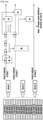
- FIG. 4a is a diagram illustrating an operating downlink data transmission / reception scheduling and uplink data transmission / reception scheduling according to an embodiment of the present disclosure
- FIG. 4b is a diagram illustrating downlink data scheduling scheme according to an embodiment of the present disclosure.
- the base station may control transmission / reception in a control channel or a data channel of the terminal through a control sub-band (c-sub-band) within the p-band configured in each terminal.
- the base station may instruct the terminal to transmit or receive a DL (downlink) data transmission / reception region or an uplink (UL) data transmission / reception area by self-band data scheduling or cross-band data scheduling.
- the base station may also instruct the terminal to change the location / size of the control sub-band in the same band by the self-band control scheduling.
- the base station may also instruct the terminal to change the location / size of an additional control sub-band in another band by the cross-band control scheduling. It is possible to further indicate the location (e.g., subframe, slot, minislot, symbol, and the like) of the time resource as well as the location of the frequency resource at the time indicating the location of the control sub-band in the same or another band.
- a preset latency value (e.g., 4 ms) or a separate latency value may be indicated to the UE through the control sub-band.
- a physical downlink shared channel (PDSCH) and a PDSCH for data transmission / reception in the same subframe may be indicated.
- PDSCH physical downlink shared channel
- a specific subframe (or a slot, a symbol, and the like) (subframe for downlink data transmission) may be required to be indicated separately.
- the base station may transmit the control signal and then indicate (delayed grant) the transmission / reception of the downlink resource after a preset latency, For example, if transmission of the PDSCH starts within a predetermined time (e.g., k symbols) after the transmission of the control signal on the PDCCH, the PDCCH and the PDSCH may exist in the same band. However, if the transmission of the PDSCH starts at a time larger than the predetermined time (e.g., k symbols) after the transmission of the control signal on the PDCCH, the PDCCH and the PDSCH may exist in different bands.
- a predetermined time e.g., k symbols
- the latency may be included in each control signal (e.g., DCI, MAC CE, or the like) or at least one latency value may be set in the terminal in advance for each s-band during a capability negotiation and connection establishment / reconfiguration procedure of the terminal.
- each control signal e.g., DCI, MAC CE, or the like
- at least one latency value may be set in the terminal in advance for each s-band during a capability negotiation and connection establishment / reconfiguration procedure of the terminal.
- the base station may transmit the latency to the terminal by each control signal based on the situation or transmits the indices for two more than latency values to the terminal by the control signal, such that the terminal is appropriately delayed and then perform the downlink reception operation. If the delay value is set to be 0 or is not set, the terminal may perform the operation of receiving the downlink data in the same TTI (or transmission time unit (TTU)).
- TTI transmission time unit
- the terminal may discard the downlink data reception of the base station when it is predicted that the band switch depending on the latency value will fail or fails. According to the configuration of the base station, the terminal may report to the base station the transport block (TB) discarding the data reception or the information on the discard (reception failure) of the terminal with the feedback information on the HARQ process ID.
- TB transport block
- the latency value may differ depending on whether the center frequency of the actual RF band of the terminal is switched. For example, in the case of a TDD terminal, the delay does not always occur for switching between the DL band and the UL band but may occur only when the center frequencies of the DL band and the UL band are switched.
- a location of another band or a location of a control sub-band within another band may be notified by the control sub-band within one band.
- the terminal may switch the RF to receive the control sub-band of another band (e.g., band 2) in one band (e.g., band 1) according to the instruction of the network, and receive the data reception or transmission information of the downlink or uplink data in the control sub-band of the band 2.
- the control sub-band within one band may inform the terminal of the location of the band including the control sub-band and / or the data region of another band not including the control sub-band.
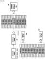
- FIG. 4b illustrates three types of band scheduling schemes in the case of the downlink.
- the terminal may configure the first band (Band # 1) and the second band (Band # 2) based on the RRC connection establishment or RRC reconfiguration procedure.
- the size of the first band is smaller than that of the second band, and the size of the second band is equal to the maximum operating bandwidth of the terminal.
- the size of the first band may be a size of four sub-bands (sub-band 7-10)
- the size of the second band may be the size of six sub-bands (sub-band 1-6)
- the maximum operation band of the terminal may equal to the size of six sub-bands.
- the terminal may monitor the control signal in the first band having a small size to reduce power consumption.
- the terminal may receive a DL control signal from a base station in an nth slot through a first band and receive the downlink control signal transmitted by the base station in the same first band as the control signal according to the indication of the control signal.
- the time resource location (e.g., start location and interval) of the data channel may be statically set for each terminal or may be dynamically indicated using the index in the slot or symbol unit by the downlink control signal.
- the scheme for indicating the self-band scheduling may inform the band index in the downlink control signal, a format of a specific control signal (e.g., when latency or resource start location information considering latency is not included in a control signal, or the like), or the like.
- the terminal may receive the downlink control signal from the base station in a (n + 1) th slot through the first band, and receive data transmitted from the base station in a (n + 2) th slot of the second band.
- the time resource location (e.g., start location and interval) of the data channel may be statically set for each terminal or may be dynamically indicated using the index in the slot or symbol unit by the downlink control signal.
- the length of the slot or the symbol may be calculated again based on the numerology information configured in the dedicated band.
- the terminal If the terminal is instructed to receive data after receiving the control signal at a shorter interval than the RF retuning latency previously reported by the mistake of the base station, the terminal 1) may inform the base station of cause information, such as the information that there is a problem in the cross-band scheduling or the information that there is the RF retuning information error by transmitting an RRC connection reconfiguration request, or 2) perform the p-band or active band switch / setup request to the base station through the RRC message or the MAC CE.
- cause information such as the information that there is a problem in the cross-band scheduling or the information that there is the RF retuning information error by transmitting an RRC connection reconfiguration request
- the terminal may inform the base station of cause information, such as the information that there is a problem in the cross-band scheduling or the information that there is the RF retuning information error by transmitting an RRC connection reconfiguration request, or 2) perform the p-band or active band switch / setup request to the base station through the RRC message
- the terminal may receive the downlink control signal from the base station in an n + 3th slot through the first band, and receive the downlink control signal of the second band according to the indication of the downlink control signal. Specifically, based on at least one information of the band index included in the downlink control signal and the downlink control channel resource location, the terminal may monitor the downlink control channel of the second band by switching a band. If the downlink control channel resource location is not separately indicated, the terminal may monitor the downlink control channel at the earliest point after the completion of the RF retuning according to the downlink control channel for each band configured by the RRC message and the resource information thereof.
- the base station may determine the time when the base station transmits the control signal to the terminal and the location of the downlink control signal to be monitored by the terminal, based on the RF retuning latency values for each terminal that is determined according to the information related to the RF retuning latency reported to the UE capability.
- the indication for the self-band scheduling operation and the cross-band scheduling operation or the band indication operation may simultaneously drop to the terminal in the downlink control channel.
- the terminal may always prioritize the self-band scheduling operation, or 2) prioritize the data transmission / reception operation determined as the high priority according to the priority (e.g., based on at least one of numerology, control signal format, traffic, service, band, PDU size, and delay requirement).
- the terminal may monitor the downlink control channel at the earliest time after the RF retuning latency after the data transmission / reception according to the self-band scheduling indication is completed.
- the base station is not allowed to indicate the scheduling operation that is not feasible within the retuning latency of the terminal.
- the base station may configure an asymmetric p-band having with different bands (e.g., location, size, and the like) in downlink and uplink for one terminal.
- the p-band needs to support both the downlink and the uplink to smoothly operate the main control functions. Therefore, even if different bands are allocated, the terminal may be understood as one p-band.
- the cross-band scheduling may be indicated by 1) one signal of the DCI / MAC CE signal for the cross-band scheduling or 2) two signals for the band switch / activation indication (e.g., DCI / MAC CE) and the self-band scheduling.
- the p-band is not changed by the cross-band scheduling, but it may be useful to transfer the p-band function if the function in the p-band is to be maintained during the band switch.
- the base station should set whether the p-band is switched in the terminal in advance by in the RRC message or include whether the p-band is switched in the DCI / MAC CE.
- the base station should set whether the p-band associated with the band switch / activation indication is switched in the terminal in advance by in the RRC message or include whether the p-band is switched in the DCI / MAC CE.
- a region to which the control signals of each band are transmitted may be designated as a specific sub-band.
- the control region may be allocated to a specific frequency region of the band.
- sub-band 1 may be the region in which the control signal is transmitted.
- the region where the control signals of each band are transmitted is not located at the specific sub-band, but may be located over the bandwidth of the band.
- the resource area to which the control signal is transmitted may not be allocated only to a specific frequency region but may be located over the whole bandwidth of the band for a specific time.
- the base station may set the terminal or define the operation according to the standard so that after the band switch of the terminal and the DL / UL data transmission / reception according to the cross-band scheduling, the operation is performed by at least one of 1) monitoring the control signal by returning the terminal to the band receiving the DL assignment or UL grant, that is, the scheduling indication, 2) monitoring the control signal by locating the terminal in the band that is the target of the scheduling indication, or 3) monitoring the control signal by switching the terminal to the band configured by the base station.
- the time when the monitoring bandwidth is applied according to the scheduling may be immediately after transmitting or receiving one DL / UL data transport block in the indicated band, or after the terminal determines that the condition satisfies the condition set by the base station.
- the conditions set by the base station may be at least one of a) the number of scheduling indications for the band, b) the complete time including the HARQ retransmission up to the N-th transmission / reception transport block, and c) the time (or corresponding timer, and the like) staying in the current monitoring bandwidth after the first cross-band scheduling indication, d) the time (or corresponding timer, and the like) during which the scheduling indication for the corresponding band was received on the successive PDCCH, e) the number of PDCCHs for which the scheduling indication for the current monitoring bandwidth is not received, f) the continuous time (or corresponding timer, and the like) of the PDCCH interval in which the scheduling indication for the current monitoring bandwidth is not received.
- the base station configures a band having a size smaller than a capable band of a terminal in the terminal as the p-band, and when a large amount of data is required to be transmitted and received, the cross-band scheduling may be indicated so as to transmit and receive a signal in a resource of a secondary band (s-band) resource set for a larger band.
- a secondary band s-band
- the terminal may be able to buffer the signal for the corresponding band only after a delay (for example, hundreds of us level). Therefore, it may be difficult to simultaneously transmit and receive a signal to the control channel and the data channel in the same subframe.
- the delay for RF / BB retuning is small (for example, several us level), such that the control channel and the data channel can be simultaneously transmitted / received in the same subframe.
- PRB physical resource block
- additional resource allocation for example, in DCI
- HARQ process is inevitably required. Therefore, a method of transmitting one transport block by bundling different PRBs of the p-band and the s-band may be considered. The method should be able to bundle and transmit one transport block even if different numerologies are applied in each band.
- the base station may use at least one of the following methods to instruct the terminal to perform band aggregation.
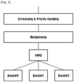
- FIG. 5 is a diagram illustrating a relationship between HARQ and a band according to an embodiment of the present disclosure.
- the terminal and / or the base station may perform a retransmission in another band for a transport block that fails to transmit in one band.
- the HARQ for the transmission failure in one band can be retransmitted in another band.
- the base station can perform the downlink data retransmission in the band 2.
- the scheduling and the priority handling may be made.
- the multiplexing may be performed when data to be transmitted exists in a band for transmitting the retransmission data.
- the base station can perform the retransmission in different bands according to the implementation by self- / cross-band scheduling. Such an operation can be performed according to the determination of the base station in the downlink, but it can be helpful in the determination of the base station on which band is suitable for retransmission based on the uplink signal of the terminal.
- the base station may periodically or dynamically allocate uplink resources for the signal transmission to the s-band of the terminal.
- the terminal may transmit the uplink signal in the transmission resource of the allocated s-band.
- the base station may instruct the operation of retransmitting the downlink data in the s-band based on the quality of the uplink signal of the terminal.
- a band ID of a candidate s-band which may be used for retransmission is transmitted to the base station along with the HARQ feedback signal of the UE, so that the base station may determine a retransmission operation based on the candidate band report of the terminal.
- the terminal first transmits a UL signal (for example, PRACH, SRS, and the like) through the UL resource allocated in a plurality of bands and the base station receives the UL signal and then determine the band in which the UL grant is indicate.
- a UL signal for example, PRACH, SRS, and the like
- the base station and the terminal may explicitly refer to a HARQ process ID in a specific band at the time of transmitting a control signal in the DCI or the UCI and a HARQ feedback message using a band ID in addition to the HARQ process ID. If it is indicated without the band ID, it is necessary to allocate a large number of HARQ process IDs in proportion to the number of bands or restrict the use of the same HARQ process ID between bands. However, considering operation, such as cross-band HARQ retransmission, restricting the HARQ process ID between bands makes it difficult to obtain additional performance.
- the physical uplink control channel (PUCCH) for the UCI transmission for the HARQ feedback of the terminal may be allocated as the RRC message through the p-band. According to the embodiment of the present disclosure, it may be operated at least one of 1) dynamically allocating the PUCCH to the s-band through the control sub-band of the p-band, or b) allocating the control sub-band belonging to the p-band is configured and the PUCCH to the same s-band through the control sub-band, according to the configuration of the base station.
- the terminal may piggyback and transmit the UCI when the resource is allocated to the PUSCH in the s-band.
- the terminal may continuously store the HARQ buffer stored for retransmission without flush.
- the terminal may flush the HARQ buffer only when the cell is released or deactivated.
- each band may be configured to a different HARQ control variable (for example, HARQ ACK/negative acknowledgment (NACK) timing, Round Trip Time, HARQ retransmission timer, and the like).
- the terminal may change the HARQ operation according to the HARQ control variable associated with the corresponding band for the HARQ operation indication including the band index.
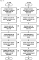
- FIG. 6 is a diagram illustrating a first operation of transmitting a common signal from a higher layer to a terminal according to an embodiment of the present disclosure
- FIG. 7 is a diagram illustrating a second operation of transmitting a common signal from a higher layer to a terminal according to an embodiment of the present disclosure
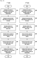
- FIG. 8 is a diagram illustrating a third operation of transmitting a common signal from a higher layer to a terminal according to an embodiment of the present disclosure
- FIG. 9 is a diagram illustrating a fourth operation of transmitting a common signal from a higher layer to a terminal according to an embodiment of the present disclosure
- FIG. 10 is a diagram illustrating control sub-band structures according to an embodiment of the present disclosure.
- the base station may be operated by setting in the terminal the fact that a SRB is transmitted to a primary control sub-band (PCS) in the p-band or a data resource set through the PCS.
- PCS primary control sub-band
- the base station and / or the terminal may transmit and receive a RRC message or a non-access stratum (NAS) message through the SRB.
- NAS non-access stratum
- a paging message is transmitted from a mobility management entity (MME) to a terminal through a NAS message.
- MME mobility management entity
- the base station may be operated by setting in the terminal the fact that a data radio bearer (DRB) is transmitted to a secondary control sub-band (SCS) in the p-band or a data resource set through the SCS.
- DRB data radio bearer
- SCS secondary control sub-band
- the PCS or the p-band may be operated so that the terminal is the same as the control resource or its bandwidth (i.e., access bandwidth) that is operated in common during the initial access procedure.
- the operation scenario may be different depending on the state of the terminal.
- the paging message may be received from a certain resource that may be obtained from a synchronization signal and a physical layer (PHY) broadcast channel (PBCH), or a paging message may be received from a paging resource received from SI.
- PHY physical layer
- a paging receiving procedure may be performed according to a paging operation and a paging resource set by the RRC message in the connected state. Meanwhile, the paging resource set in the connected state may be different from the access bandwidth.
- the paging message may be a paging message corresponding to another service / slice. Since the terminal may see only a part of the bands corresponding to the configured band of the whole system bands, the base station may have a burden to separately transmit a common signal dropping from the higher layer, for example, an SI message for different terminals for viewing different bands.
- the base station may copy SI information (common signal) 610 into three and transmit each of the three copied signals 620, 623, and 625 to three terminals (UE 1 / UE 2 / UE 3) through separate control channels (e.g., (c-sub-band 1, c-sub-band 5, and c-sub-band 12).
- the base station interprets the paging message and requires an effort to generate paging messages for each band 630, 633, and 635 for the terminals UE 1, UE 2, and UE 3 included in the bands 630, 633, and 635 and transmit the paging messages to the terminals UE 1, UE 2, and UE 3.
- the paging transmission opportunity may be determined according to a system frame number (SNF) and a subframe index.
- SNF system frame number
- the idle mode UE sets the paging transmission opportunity from the MME and monitors the downlink control channel (PDCCH) in the frame and the subframe corresponding to the set paging transmission opportunity even if passing through several base stations to receive the paging message as resources identified by a paging radio network temporary identifier (P-RNTI). More specifically, the terminal may set as a first paging opportunity a subframe (paging occasion) of how many frames (paging frame) are located based on system frame 0 and set a paging opportunity as being repeated for each DRX cycle represented in a frame unit.
- P-RNTI paging radio network temporary identifier
- the paging frame number and the paging occasion in the paging configuration may be set in the terminal by allowing the base station to directly transmit the value to the terminal, but in the case of the paging frame number, the terminal may perform the calculation based on other parameters (e.g., DRX cycle, the number of paging frames in the DRX cycle, the number of paging occasions in the DRX cycle, the terminal ID, and the like) or in the case of the paging occasion, may perform the calculation based on other variables (e.g., the number of paging frames in the DRX cycle, the number of paging occasions in the DRX cycle, the terminal ID, the number of subframes in the paging frame, etc.).
- other parameters e.g., DRX cycle, the number of paging frames in the DRX cycle, the number of paging occasions in the DRX cycle, the terminal ID, the number of subframes in the paging frame, etc.
- One Paging Frame is one Radio Frame, which may contain one or multiple Paging Occasion(s).
- PF Paging Frame
- the UE needs only to monitor one PO per DRX cycle.
- PBM Paging Narrowband
- i_s floor(UE_ID/N) mod Ns
- PNB floor(UE_ID/(N ⁇ Ns)) mod Nn
- the DRX cycle includes a value set by the NAS for each terminal and a common setting value of the base station, and the smaller of the value and the common setting value may be used if both are set.
- a plurality of common signaling resources may be set in one subframe (or slot), and therefore if the paging configuration method of the MME may identify the common signaling resource considering the common signaling resources, It is possible to prevent waste caused by copying common signaling resources to a plurality of common signaling resources.
- a band index and a common signaling resource index can be used equally.
- a common signaling resource index is used.
- an additional common signaling resource index may be configured when a common signaling resource is allocated to a specific band by the RRC message.
- the common band index may be calculated based on at least one of an existing system frame number, a subframe, DRX cycle information, or other information for obtaining such information in the paging configuration.
- the terminal ID may take modular arithmetic by the number (Ncs) of common signaling resources that the base station has set as SI to specify one of the common signaling resources.
- the terminal ID may be any value derived from an international mobile subscriber identity (IMSI) or an IMSI.
- the band / common signaling resource index may be calculated based on an output value of a function that uses a value of at least one of the DRX cycle, the number of paging frames in the DRX cycle, the number of paging occasions in the DRX cycle, the terminal ID, and the number of subframes in the paging frame, and the number of common band / common signaling resources as an input of a function.
- the terminal may receive the common band or the common signaling resource from the base station by the RRC message in the RRC connection state.
- the idle mode UE in which a terminal does not receive the common band or the common signaling resource from the base station that the terminal newly camps may first perform a random access procedure to receive the common signaling resource from the base station through the RRC message.
- the paging configuration of the MME is the same as the prior art, and only a band or a common signaling resource monitored by a terminal among a plurality of resources in a specific period may be allocated in one base station.
- the base station may calculate a maximum value Np (e.g., the number of frames x the number of common signaling resources in subframes) of the paging resource within a period set based on the information (e.g., at least one of UE ID, IMSI, or the like) of the terminal receiving the paging.
- the base station may determine an index for one resource according to an equation of (UE ID) mod Np.
- the base station / terminal may determine a resource to receive paging in the set period in such a manner to count the common signaling resources in the subframe using the index of the determined resource.
- a method for determining paging occasions for each terminal by using one equation for time axis information e.g., paging frame and paging subframe
- resources for each terminal by another equation for frequency axis information e.g., band index or common signaling resource index
- the paging operation described above may operate in a similar manner even when the terminal is in the inactive mode other than the IDLE mode.
- the above-described paging resource may be set as a plurality of paging resource areas identified for service / numerology / slice support.
- the paging reception operation may be performed in the corresponding paging resource area.
- the base station When the terminal is operated for a plurality of services / numerologies / slices, 1) the base station transmits paging signals for each of a plurality of paging resource areas to the terminal in an overlapping manner, or 2) the base station transmits only paging signal for one paging resource area to the terminal and simultaneously monitors the paging occasions of the plurality of paging resource areas, or 3) the base station may transmit the paging signal to the terminal in the paging resource area corresponding to one service / numerology / slice selected according to the set priority and the terminal may also monitor the paging occasion of the paging resource area. To support the operation, the base station may inform the terminal of the relationship between each paging resource area and service / numerology / slice through SI.
- a common band 730 is set so that all terminals can receive one common signal as in the existing LTE, and the base station may set an operation of setting when the terminal receives a common band 730 in the terminal in advance by the RRC message.
- the base station may be configured to operate the terminal according to at least one of a) allowing the terminal to receive the common band 730 at a specific time, or b) giving only the opportunity for the terminal to receive the common band 730 at a specific time and determining whether the terminal receives the common band 730 according to the state of the band in which the terminal is operating, or c) giving only the opportunity for the terminal to receive the common band 730 at a specific time, and allowing the terminal to receive the common band 730 only in the case where there is no operation indicated in a band in which the terminal is operating.
- at least two of the methods a), b) and c) may be separately set.
- a structure in which one control sub-band is shared by a plurality of bands 730, 733, and 735 is proposed.
- c-sub-band 4 may be shared by band 1 730 and band 2 733
- c-sub-band 10 may be shared by band 2 733 and band 3 735.
- the common signals to be copied / partitioned may be reduced to two signals 720 and 725.
- This scheme is not as efficient as the example of FIG. 7 , but can dynamically control the inter-band shared control sub-band to minimize inefficiency.
- the base station may copy SI information (common signal) 810 into three and transmit each of the two copied signals 820 and 825 to three terminals (UE 1 / UE 2 / UE 3) through separate control channels (e.g., (c-sub-band 1, c-sub-band 5, and c-sub-band 12).
- the base station interprets the paging message and requires an effort to generate paging messages for each band 830, 833, and 835 for the terminals UE 1, UE 2, and UE 3 included in the bands 830, 833, and 835 and transmit the paging messages to the terminals UE 1, UE 2, and UE 3.
- the base station may indicate whether to dynamically receive a common band 930 through bands (band 1, band 3) 940 and 945 configured in each terminal (e.g., UE 1 and UE 3) to the terminal
- the base station may set the location / size of the common band 930 and its control sub-band (e.g., c-sub-band 8, 9) in the terminal in advance by the RRC message.
- the base station may be operated according to at least one of a) a method for transmitting by a base station, a return (or switch) indication to the terminal in the common band 930, b) a method for setting it in a terminal to return the terminal to a dedicated band after a preset timer expires or setting it in the terminal by the base station, c) a method for setting it in the terminal in advance so that the terminal returns to the dedicated band after performing (e.g., receiving SI or paging) a targeted operation in the common band 930 or setting it in the terminal by the base station, or d) a method for receiving, by a terminal, a p-band change control signal in the common band 930 and setting a dedicated band as a p-band and moving the dedicated band.
- a method for transmitting by a base station, a return (or switch) indication to the terminal in the common band 930 b) a method for setting it in a terminal to return the terminal to a dedicated band after a preset
- control sub-band 1 may be allocated to band 1 1010
- control sub-band 5 may be assigned to band 2 1013
- control sub-band 13 may be assigned to band 3 1015.
- a sub-band for data transmission other than a control sub-band may be shared by a plurality of bands.
- band 1 1010 and band 2 1013 may share sub-bands 3 and 4 as sub-bands for data transmission.
- control bands may commonly be allocated to a plurality of bands (shared control sub-bands among bands).
- band 1 1020 and band 2 1023 may be shared by control sub-band 3.
- Band 2 1023 and band 3 1025 may share control sub-band 11.
- one common control band may be configured so that all terminals can receive one common signal.
- a common band 1030 including control sub-bands 8, 9 for all terminals may be configured.
- the terminal may perform the handover or the band recovery procedure according to the degradation in the signal strength / quality of the base station.
- the handover is a procedure for performing RRC connection reconfiguration to a target cell according to a determination of the serving base station in response to the degradation in the serving cell signal strength / quality.
- the band recovery proposed in an embodiment of the present disclosure is a procedure for resetting the p-band while maintaining the connection between the serving base station and the terminal.
- the terminal may be operated by either handover or band recovery depending on timers, parameters, and weights set as different values for each procedure. For example, in a sub 6 GHz licensed band, the handover may be important and in a band above 6 GHz, the band recovery may be important. In addition, in the unlicensed band where LBT (listen before talk) regulation is applied, the band recovery may be important. According to an embodiment of the present disclosure, the terminal may also change the weight according to the operation frequency, not by the configuration of the base station.
- the RLF for the serving base station may be determined according to whether a sum of the aggregated RLC packet retransmission frequencies before the recovery timer for the p-band expires exceeds the maximum retransmission frequency.
- the p-band recovery timer is activated after the failure for the p-band is determined. If the p-band recovery is not completed until the timer expires, the terminal may determine the RLF for the serving base station.
- the band recovery process is mainly applied to the p-band, but may also be applied to the common band or the s-band according to the embodiment. The following four band recovery procedures may be possible.
- FIG. 11 is a diagram illustrating a band recovery process according to an embodiment of the present disclosure
- FIG. 12 is a diagram illustrating a band recovery process according to an embodiment of the present disclosure
- FIG. 13 is a diagram illustrating a band recovery process according to an embodiment of the present disclosure
- FIG. 14 is a diagram illustrating a band recovery process according to an embodiment of the present disclosure.
- FIG. 11 illustrates flowcharts of operations of the base station (1st node) and the terminal (2nd node) according to a method in which the base station triggers a band recovery process.
- the base station may reconfigure another band as a P-band based on the measurement report.
- the base station may configure, to the terminal, a first band as a primary band for serving cell measurement in operation 1110, and configure a second band that is not configured as a primary band for serving cell measurement in operation 1120.
- the base station may receive measurement report for the first band and/or the second band from the terminal.
- the base station may determine whether to change the primary band with the second band based on the measurement report received from the terminal in operation 1130. Further, in operation 1150, the base station may perform configuration to the terminal to change the primary band with the second band as a new primary band according to the determination in operation 1140.
- the terminal may receive configuration for the first band as a primary band from the base station for serving cell measurement in operation 1160, and receive configuration for the second band that is not configured as a primary band for serving cell measurement in operation 1170.
- the terminal may transmit the measurement report for the first band and/or the second band to the base station.
- the terminal may receive the configuration from the base station to change the primary band with the second band as a new primary band according to the determination of the base station in operation 1140.
- the terminal changes the primary band with the second band as a new primary band according to the configuration of the base station, and may apply attributes and measurement operation applied to the previous primary band to the new primary band.
- FIG. 12 illustrates flowcharts of operations of the base station (1st node) and the terminal (2nd node) according to a method in which the terminal triggers a band recovery process according to an embodiment of the present disclosure.
- the terminal detecting low signal quality of the base station may inform the base station of a candidate band to which the terminal will move. At this time, the terminal may transmit, to the base station, information on the candidate band to which the terminal will move through an UL resource allocated in advance. Further, the base station may reconfigure the P-band based on the information received from the terminal.
- the base station may configure a first band as a primary band to the terminal for a purpose of serving cell measurement in operation 1210. Further, the base station may set an UL resource for problem report on the primary band to the second band that is not configured as the primary band in operation 1215.
- the terminal may determine whether a validity condition based on a channel state of the primary band (first band) is met, and determine whether a failure of the primary band occurs. If the channel of the primary band does not meet the validity condition, the terminal may transmit problem report thereon to the base station, and the base station may receive the report message in operation 1220. At this time, the base station may receive report on the second band in addition to the report on the primary band from the terminal.
- the base station may determine whether to change the primary band with the second band as a new primary band in operation 1225. At this time, the base station may determine whether to determine the second band as a new primary band by referring to at least one of a result of measurement on the second band and signal quality of the first band in which the problem occurs. Further, in operation 1230, the base station may perform configuration to the terminal to change the primary band with the second band as a new primary band according to the determination in operation 1225.
- the terminal may receive the configuration of the first band as a primary band for the purpose of serving cell measurement from the base station in operation 1240. Further, the terminal may receive setting an UL resource for problem report on the primary band to the second band that is not configured as the primary band from the base station in operation 1245. In operation 1250, the terminal may determine whether a validity condition based on a channel state of the primary band (first band) is met, and determine whether a failure of the primary band occurs. Further, if the channel of the primary band does not meet the validity condition, the terminal may transmit problem report thereon to the base station via the second band in operation 1255.
- the terminal may receive the configuration from the base station to change the primary band with the second band as a new primary band according to the determination of the base station in operation 1225.
- the terminal changes the primary band with the second band as a new primary band according to the configuration of the base station, and may apply attributes and measurement operation applied to the previous primary band to the new primary band.
- the base station/terminal triggers the band recovery process, and flowcharts of operations of the base station (1st node) and the terminal (2nd node) according to an UL-based band recovery process are illustrated.
- Both the base station and the terminal detect low signal quality, and accordingly, the base station may reconfigure a new band as a P-band according to probing signal transmission of the base station and signal transmission of the terminal in response thereto before a certain timer expires.
- the base station may configure a first band as a primary band to the terminal for a purpose of serving cell measurement in operation 1310. Further, the base station may set an SRS resource to the second and third bands that are not configured as the primary band in operation 1315. Further, the base station may set a resource for probing signal transmission of the base station for the primary band (first band).
- the second band may be one or more bands in view of the base station, and the third band may be at least one of a plurality of second bands that is determined by the terminal.
- the terminal may determine whether a validity condition based on a channel state of the primary band (first band) is met, and determine whether a failure of the primary band occurs.
- the base station may determine whether a validity condition based on a channel state of the first band is met based on the SRS signal of the terminal, and determine whether a failure of the primary band occurs. Further, if a channel of the primary band does not meet the validity condition, in operation 1325, the base station starts a first timer and may transmit a probing signal to the terminal via the second band until the first timer expires. When the probing signal is transmitted, the base station starts a second timer, and in operation 1330, the base station may wait to receive a response signal until the second timer expires.
- the base station may determine whether to change the primary band with the third band as a new primary band based on the response signal of the terminal for the probing signal transmitted via the second band.
- the response signal may be received via the third band.
- the base station may perform configuration to the terminal to change the primary band with the third band as a new primary band according to the determination in operation 1335.
- the terminal may receive the configuration of the first band as a primary band for the purpose of serving cell measurement from the base station in operation 1340. Further, the terminal may receive, from the base station, setting for an SRS resource of the terminal to the second and third bands that are not configured as the primary band in operation 1345. Further, the terminal may receive, from the base station, setting for a resource for probing signal transmission of the base station for the primary band (first band). In operation 1350, the terminal may determine whether a validity condition based on a channel state of the primary band (first band) is met, and determine whether a failure of the primary band occurs. Further, the terminal may transmit the SRS signal to the base station if a failure of the primary band occurs.
- the terminal starts a third timer and may wait to receive a probing signal of the base station via all the configured second bands until the third timer expires.
- the third timer may be the same as the first timer.
- the terminal receives the probing signal in operation 1355, the terminal starts a fourth timer therefor, and in operation 1360, the terminal may transmit a response signal to the base station via the third band.
- the fourth timer may be the same as the second timer.
- the terminal may receive the configuration from the base station to change the primary band with the third band as a new primary band according to the determination of the base station in operation 1335.
- the terminal changes the primary band with the third band as a new primary band according to the configuration of the base station, and may apply attributes and measurement operation applied to the previous primary band to the new primary band.
- the base station/terminal triggers a band recovery process, and flowcharts of operations of the base station (1st node) and the terminal (2nd node) according to a DL-based recovery method is illustrated.
- Both the base station and the terminal detect low signal quality, and accordingly, the base station may reconfigure a new band as a P-band according to a measurement report of the terminal before a certain timer expires.
- the base station may configure a first band as a primary band to the terminal for a purpose of serving cell measurement in operation 1410. Further, the base station may set an RS resource of the base station to a second band and a third band that are not configured as a primary band in operation 1415, and may set, to the terminal, a timer-based measurement report for the set RS resource.
- the second band may be one or more bands in view of the base station
- the third band may be at least one of a plurality of second bands that is determined by the terminal.
- the terminal may determine whether a validity condition based on a channel state of the primary band (first band) is met, and determine whether a failure of the primary band occurs.
- the base station may determine whether a validity condition based on a channel state of the first band is met based on the measurement report of the terminal, and determine whether a failure of the primary band occurs. If a channel of the primary band does not meet the validity condition, in operation 1425, the base station starts a first timer and a second timer and may transmit a reference signal (RS) to the terminal via the second band until the first timer expires. In operation 1430, the base station may wait to receive the measurement report until the second timer expires. The measurement report may be received via the third band.
- RS reference signal
- the base station may determine whether to change the primary band with the third band as a new primary band based on the measurement report of the terminal for the RS transmitted via the second band. Further, the base station may perform configuration to the terminal to change the primary band with the third band as a new primary band according to the determination in operation 1435.
- the terminal may receive the configuration of the first band as a primary band for the purpose of serving cell measurement from the base station in operation 1440. Further, the terminal may receive the setting of the RS resource of the base station to the second band and the third band that are not configured as a primary band in operation 1445, and may receive the setting of the timer-based measurement report for the set RS resource. In operation 1450, the terminal may determine whether a validity condition based on a channel state of the primary band (first band) is met, and determine whether a failure of the primary band occurs. Further, if the channel of the primary band does not meet the validity condition, the terminal may start a third timer and a fourth timer.
- the third timer is the same as the first timer, and the fourth timer may be the same as the second timer.
- the terminal may receive the RS of the base station via all configured second bands until the third timer expires.
- the terminal may transmit a measurement report thereon to the base station via the third band until the third timer expires in operation 1460
- the terminal may receive the configuration from the base station to change the primary band with the third band as a new primary band according to the determination in operation 1435.
- the terminal changes the primary band with the third band as a new primary band according to the configuration of the base station, and may apply attributes and measurement operation applied to the previous primary band to the new primary band. Meanwhile, in determining signal quality in a specific band, the following four options may be considered.
- a band recovery operation basically is a process of measuring channel quality for a plurality of bands and switching a P-band with other band according to a result of the measurement.
- the operation of measuring channel quality for each band and the band switch process may be separated and the band switch process may be performed by one of the following methods.
- a retain time of the switched band may be valid by meeting one of conditions of 1) until a next indication to switch is issued, 2) after a predetermined time k (e.g., symbol, slot, subframe, frame, or the like), and 3) after a predetermined time k (e.g., symbol, slot, subframe, frame, or the like) set by the base station by the RRC message. If the retain time expires, the terminal may return to the band state before the switching.
- a predetermined time k e.g., symbol, slot, subframe, frame, or the like
- the deactivation may be performed by a timer without a separate indication. For example, when the terminal monitors a downlink control channel of a specific band, if a signal from the base station is not received by the terminal via the band until a certain timer expires, the terminal may deactivate the band.
- FIG. 15 is a diagram illustrating a monitoring bandwidth of a terminal for a serving base station and a neighboring base station according to an embodiment of the present disclosure
- FIG. 16 is a diagram illustrating a monitoring bandwidth of a terminal for a serving base station and a neighboring base station according to an embodiment of the present disclosure
- FIG. 17 is a diagram illustrating a monitoring bandwidth of a terminal for a serving base station and a neighboring base station according to an embodiment of the present disclosure
- FIG. 18 is a diagram illustrating a monitoring bandwidth of a terminal for a serving base station and a neighboring base station according to an embodiment of the present disclosure.
- the terminal needs to always monitor a DL control channel even when receiving a data service of small capacity. Therefore, if a monitoring bandwidth is large, power consumption may be large even at the time of data service of small capacity.
- the terminal may receive a setting of a monitoring resource having a small size from the serving base station for purposes of reduction in power consumption and the like and receive the DL control channel through the resource.
- a band scheduling method for, such as operation is described. However, even when the terminal performs an operation of reception from the serving base station via a limited band (BW), in the case of connected mode terminal, the entire band may need to be monitored in order to perform a radio resource management (RRM) measurement operation of a neighboring cell. Meanwhile, the measurement for the serving base station may be performed by at least one of the following methods.
- a terminal 1510 may receive a control channel from a serving base station (gNB1) 1520 via a partial band 1530. Further, the terminal 1510 may be set to monitor a wide band 1540 for RRM measurement for a neighboring base station (gNB2) 1525, that is, in order to receive a synchronization signal (sync, PBCH) 1555 and a reference signal (RS) 1550. This may result in high power consumption of the terminal 1510.
- gNB1 serving base station
- gNB2 neighboring base station
- RS reference signal
- the serving base station 1520 may configure a dedicated RRM band 1620 for performing the RRM measurement for the neighboring base station 1525 to the terminal 1510.
- An active band 1610 operated in the serving base station 1520 may include the dedicated RRM band 1620.
- the terminal 1510 may perform the RRM measurement while not following measurement gap configuration, if not changing a center frequency.
- the serving base station 1520 may configure a dedicated RRM band 1720 for performing the RRM measurement for the neighboring base station 1525 to the terminal 1510. If the active band operated in the serving base station 1520 may not include the dedicated RRM band 1720, the terminal may perform measurement according to measurement gap configuration.
- the serving base station 1520 may configure to the terminal 1510 a dedicated RRM band for performing the RRM measurement for the neighboring base station 1525 and a reference band 1820 for synchronization.
- the terminal 1510 may include the reference band 1820 in the active band 1810 operated in the serving base station 1520, but if the center frequency needs to be changed, may first performing synchronization for the neighboring base station 1525 according to the measurement gap configuration.
- the terminal 1510 may include the dedicated band 1820 in the active band 1810 operated in the serving base station 1520, but if the center frequency is not changed, may measure an RS of the neighboring base station in the current active band regardless of the measurement gap configuration.
- the base station may configure a separate band to the terminal for RRM measurement for the neighboring base station.
- the terminal may receive configuration of a band for measurement from the serving base station or neighboring base station according to at least one the following methods.
- the base station may configure a band to the terminal by interworking with a band for scheduling for RRM measurement for the neighboring base station.
- the base station may inform the terminal of a band index together with resource setting for one or more CSI-RSs in RRM measurement configuration.
- the band index also has the numerology information, thus numerology for the CSI-RS resource may also follow the numerology information interworking with the indicated band.
- the serving base station may separately or integrally set resource areas for receiving a control channel of the serving base station and an RS of the neighboring base station to the terminal.
- the terminal may perform a control channel reception operation and a neighboring base station measurement operation by a time division multiplexing (TDM) scheme or frequency division multiplexing (FDM) scheme, separately.
- TDM time division multiplexing
- FDM frequency division multiplexing
- the serving base station may allocate a measurement gap to the terminal.
- the base station may be operated according to at least one of the followings: a) performing configuration so that the terminal necessarily receives a signal of the neighboring base station at a specific point in time, b) performing configuration so that the terminal merely has an opportunity the terminal to receive a signal of the neighboring base station at a specific point in time and determines whether to receive the signal of the neighboring base station based on an operation condition for the serving base station of the terminal, and c) performing configuration so that the terminal merely has an opportunity the terminal to receive a signal of the neighboring base station at a specific point in time and receives the signal of the neighboring base station only when there is no operation indicated for the serving base station.
- the terminal may reflect only a measurement result in a RRM BW as an input value of an L3 filter.
- the terminal may separate each measurement result for each BW when performing measurement both in a RRM BW and an active band BW. Further, the terminal may abandon the existing L3 filtering and make a new start if an RRM BW is reset, or an averaging value for the RRM BW is not received from L1 within a predetermined time.
- one or a plurality of BWs may be configured to the terminal according to determination of the base station, and if the plurality of RRM BWs are set, the terminal may be operated by selecting an RRM BW in which retuning latency is shortest according to a relationship with a band being operated.
- the terminal may be operated by preferentially selecting an RRM BW including an SS among the plurality of RRM BWs.
- the terminal may be operated by selecting an RRM BW based on priority for the plurality of RRM BWs that is set by the base station and a retuning latency constraint.
- the terminal may select an RRM BW with highest priority among RRM BWs in which retuning latency is shorter than time k (e.g., symbol, slot, subframe, frame, or the like) for switching to the RRM BW in the activated band or primary band.
- time k e.g., symbol, slot, subframe, frame, or the like
- the base station may set a frequency resource for performing RRM measurement to the terminal, and this will hereinafter be referred to as RRM BW. Further, the base station may configure one or more bands to the terminal for scheduling, or the like. If the RRM BW and a BW allocated to the band may be switched to each other without RF retuning, the terminal may perform the RRM measurement during signal transmission and reception with the base station. However, if the terminal may switch the RRM BW and the BW of the band only if the RF retuning is performed, the RRM measurement may be performed according to measurement gap configuration of the base station. A latency by the retuning may be determined by various factors, such as whether a center frequency of the operating RF band is changed, whether numerology needs to be changed for measurement, and the like.
- whether to apply the measurement gap may be optionally determined depending on a relationship of the RRM BW for the current P-band, active band, or a band being used for data transmission and reception. For example, if RF retuning for switching to the RRM BW is performed for one or more bands in which the terminal is currently operated among the plurality of bands or an RF retuning latency time is longer than a predetermined latency, the configured measurement gap may be activated.
- the terminal may prepare the RRM measurement in the measurement gap.
- the terminal may complete the RF retuning in advance to perform measurement for a measurement resource set in the RRM BW.
- the terminal may perform the RRM measurement in the measurement gap.
- the terminal may complete the RF retuning in advance to perform measurement for a measurement resource set in the RRM BW. If the RF retuning is performed and it is determined that the measurement gap reaches the end point in time within the time that is a combination of the RF latency and the minimum measurement time, the terminal does not perform the RRM measurement in the measurement gap.
- the base station may make inquiries about a cause thereof, and the terminal may report an index value including information on the cause in response to the request of the base station.
- the terminal may transmit a measurement gap reconfiguration request to the base station, and the base station may make determination based on a cause of the measurement gap reconfiguration request transmitted from the terminal and terminal capability information to reconfigure the measurement gap.
- FIG. 19 is a diagram illustrating a flexible BW system desired in a 5G communication system according to an embodiment of the present disclosure.
- the flexible BW system is configured by three BWs including an access BW, an idle mode BW, and a connected mode BW, and switching between them.
- the access BW means a minimum BW used by the terminal for performing an initial access process, such as cell selection, SI acquirement, random access, and the like.
- the access BW basically may be determined in advance according to a carrier frequency.
- the terminal may receive access BW information or information for acquiring access BW through the anchor base station.
- the access BW is configured of a sub-band and a band exemplified in an embodiment of the present disclosure, and the base station may configure the access BW to the terminal through SI or RRC message.
- a location of a basic downlink control channel may be set by the number of control sub-bands and symbols.
- a location of a basic downlink data channel may be set by a band corresponding to a control sub-band.
- a basic DL-SCH (downlink shared channel) of an L2 layer may be set.
- the base station may set a reference frequency location (e.g., carrier center frequency, or the like) for calculating the BW information together to the terminal.
- the idle mode BW means a BW set for performing a process, such as additional SI acquirement, paging, random access, and the like, by the terminal.
- the idle mode BW may be the same as the access BW, but a BW different from the access BE may be set as the idle mode BW to sufficiently improve utilization of broadband.
- SI is generally used, but in some cases, an RRC message may be used for the setting.
- the terminal may receive setting of the idle mode BW in advance from the base station in a connected state, or may acquire information for determining the idle mode BW (e.g., the number of bands of the base station, band/sub-band configuration, the number of common signaling resources, and the like).
- the connected mode BW means a BW set to the terminal for configuration of the control/data channel.
- the control sub-band and band information may be set through an RRC message.
- additional downlink control/data channel and DL-SCH may be set.
- the terminal may receive setting for the connected mode BW through the random access process. The terminal may be operated according to the control/data channel set to the connected mode BW by switching to the connected mode.
- a synchronization signal (SS) and a CSI-RS may be considered for the RRM measurement.
- the synchronization signal is transmitted and received in the access BW, and if cell-specific, the CSI-RS may be transmitted and received in the idle mode BW or the connected mode BW, and if UE-specific, the CSI-RS may be transmitted in the connected mode BW.
- the base station may operate the BW according to various situations for each terminal.
- the terminal may perform measurement by setting a synchronization signal in the access BW as a reference signal for the RRM measurement. Further, the terminal may be operated by assuming that the idle mode BW is the same as the access BW if there is no separate setting for the idle mode BW. For example, the idle mode operation, such as cell (re-)selection and the like may be performed according to a result of measurement for the SS.
- the terminal may receive setting of an idle mode BW that includes the access BW and is large than the access BW from the base station through the SI. Further, the terminal may receive setting of a cell-specific CSI-RS for the idle mode BW.
- the terminal may perform measurement for the cell-specific CSI-RS according to measurement configuration, and perform the idle mode operation, such as cell (re-)selection based on a result thereof.
- the terminal measures an SS for a base station that does not use the cell-specific CSI-RS, thus may be operated by reflecting an offset value for correcting an error between performance indices. According to some measurement configuration, the terminal may be operated based on a representative value for the SS and cell-specific CSI-RS measurement result.
- the terminal may receive setting of an idle mode BW that does not include the access BW from the base station through the SI. Further, the terminal may receive setting of a cell-specific CSI-RS for the idle mode BW. The terminal may perform measurement for the cell-specific CSI-RS according to measurement configuration, and perform the idle mode operation, such as cell (re-)selection based on a result thereof. The terminal measures an SS for a base station that does not use the cell-specific CSI-RS, thus may be operated by reflecting an offset value for correcting an error between performance indices.
- the neighboring base station transmits an SS in the access BW
- the terminal monitors an idle mode BW different from the access BW set by the serving base station
- the serving base station may configure a measurement gap or set a measurement resource so that an access BW of the neighboring base station is monitored by RF retuning to the terminal.
- the terminal may measure the SS of the neighboring base station in the configured measurement gap or the set measurement resource and reflect the offset value for error correction, thereby performing the idle mode operation, such as cell (re-)selection, and the like.
- the terminal may receive setting of a connected mode BW that includes the access BW or idle mode BW and is the same as or large than the access BW or idle mode BW from the base station through the RRC message. Further, the terminal may receive setting of a cell/UE-specific CSI-RS for the connected mode BW.
- the terminal may perform measurement for the cell/UE-specific CSI-RS according to measurement configuration, and perform the connected mode operation, such as RRM measurement and report, and the like based on a result thereof.
- the terminal may perform measurement in order of priority, that is, in order of an UE-specific CSI-RS, a cell-specific CSI-RS, and an SS.
- the terminal may report the measurement results for each kind of measured RS to the base station.
- the terminal may receive setting of a connected mode BW that does not include the access BW or idle mode BW or partially overlaps with the access BW or idle mode BW from the base station through the RRC message. Further, the terminal may receive setting of a cell/UE-specific CSI-RS for the connected mode BW.
- the terminal may perform measurement for the cell/UE-specific CSI-RS according to measurement configuration, and perform the connected mode operation, such as RRM measurement and report, and the like based on a result thereof.
- the terminal may report the measurement results for each kind of measured RS to the base station.
- the terminal measures an SS for a base station that does not use the cell/UE-specific CSI-RS, thus may be operated by reflecting an offset value for correcting an error between performance indices.
- the neighboring base station transmits an SS in the access BW
- the terminal monitors a connected mode BW different from the access/idle BW set by the serving base station
- the serving base station may configure a measurement gap or set a measurement resource so that an access/idle BW of the neighboring base station is monitored by RF retuning to the terminal.
- the terminal may measure the SS of the neighboring base station in the configured measurement gap or the set measurement resource and reflect the offset value for error correction, thereby performing the connected mode operation, such as RRM measurement and report, and the like.
- FIG. 20 is a diagram illustrating a configuration of a terminal according to an embodiment of the present disclosure.
- the terminal may include a transceiver 2010 performing signal transmission and reception with a network entity, such as other terminal and base station, and a controller 2020 controlling all operations of the terminal.
- a network entity such as other terminal and base station
- the controller 2020 and the transceiver 2010 are not necessarily implemented as separate apparatuses, but may be implemented as one component in a form like a single chip.
- the controller 2020 and the transceiver 2010 may be electrically connected to each other.
- the transceiver 2010 may include a transmitter 2013 and a receiver 2015. Further, the terminal may further include a memory 2030.
- the controller 2020 of the terminal controls the terminal to perform any one of the operations in the embodiments described above.
- the controller 2020 of the terminal may receive, from a base station, a first message including configuration information of at least one band, receive, from the base station, a second message for activating a band among the at least one band, and activate the band according to the second message.
- the controller 2020 may include a system decision unit 2023, a BW controller 2025, and a measurement unit 2027.
- the system decision unit 2023 may control the operation of the terminal according to the configuration of the base station described above, and the BW controller 2025 may determine and control an operating bandwidth of the terminal.
- the measurement unit 2027 may measure a reference signal from the base station and store the measurement result in the memory 2030. Meanwhile, the system decision unit 2023, the BW controller 2025, and the measurement unit 2027 are not necessarily implemented as separate modules, but may be implemented as one component in a form like a single chip.
- the transceiver 2010 of the terminal may transmit and receive a signal according to any one of the operations in the embodiments described above.
- the controller 2020 may be, for example, a circuit, an application-specific circuit, or at least one processor. Further, the operations of the terminal may be implemented by providing a memory device (memory 2030) storing a corresponding program code in any component in the base station. For example, the controller 2020 may execute the operations described above by reading and executing the program code stored in the memory device by a processor, a central processing unit (CPU), or the like.
- a memory device memory 2030
- CPU central processing unit
- the configuration diagram of the terminal illustrated in FIG. 20 the exemplified diagram of the control/data signal transmission method, the exemplified diagram of the operating process of the terminal, and the configuration diagrams of the terminal apparatus are not intended to limit the scope of rights of the present disclosure.
- all components, entities, or operations of an operation illustrated in FIG. 20 are not to be interpreted as being an essential constituent element for implementing the present disclosure, and may be implemented without departing from the gist of the present disclosure.
- FIG. 21 is a diagram illustrating a configuration of a base station according to an embodiment of the present disclosure.
- the base station may include a transceiver 2110 performing signal transmission and reception with other network entity, such as a terminal and an MME, and a controller 2120 controlling all operations of the base station.
- all operations for supporting the synchronization described above may be understood as being performed by the controller 2120.
- the controller 2120 and the transceiver 2110 are not necessarily implemented as separate apparatuses, but may be implemented as one component in a form like a single chip. Further, the controller 2120 and the transceiver 2110 may be electrically connected to each other.
- the transceiver 2110 may include a transmitter 2113 and a receiver 2115. Further, the base station may further include a memory 2130.
- the controller 2120 of the base station controls the base station to perform any one of the operations in the embodiments described above.
- the controller 2120 of the base station may transmit, to a terminal, a first message including configuration information of at least one band, and transmit, to the terminal, a second message for activating a band among the at least one band.
- the transceiver 2110 of the base station may transmit and receive a signal according to any one of the operations in the embodiments described above.
- the controller 2110 may be, for example, a circuit, an application-specific circuit, or at least one processor. Further, the operations of the base station may be implemented by providing a memory device (memory 2130) storing a corresponding program code in any component in the base station. For example, the controller 2110 may execute the operations described above by reading and executing the program code stored in the memory device by a processor, a CPU, or the like.
- the operations of the base station or the terminal may be implemented by providing a memory device (memory 2130) storing a corresponding program code in any component in the base station or terminal apparatus.
- a memory device memory 2130
- the controller 2020 or 2120 of the base station or the terminal may execute the operations described above by reading and executing the program code stored in the memory device 2030 or 2130 by a processor or a CPU.
- the base station or the terminal apparatus may be operated by using a hardware circuit, for example, a complementary metal oxide semiconductor-based logic circuit, firmware, software and/or hardware, or a combination of firmware and/or software inserted in a machine-readable medium.
- a hardware circuit for example, a complementary metal oxide semiconductor-based logic circuit, firmware, software and/or hardware, or a combination of firmware and/or software inserted in a machine-readable medium.
- various electric structures and methods may be implemented using transistors, logic gates, and electric circuits, such as an application specific integrated circuit (ASIC).
- ASIC application specific integrated circuit
Landscapes
- Engineering & Computer Science (AREA)
- Signal Processing (AREA)
- Computer Networks & Wireless Communication (AREA)
- Computer Security & Cryptography (AREA)
- Mobile Radio Communication Systems (AREA)
Claims (15)
- Verfahren, welches von einem Endgerät in einem drahtlosen Kommunikationssystem ausgeführt wird, wobei das Verfahren Folgendes umfasst:Empfangen einer Radio Resource Control(RRC)-Nachricht, die Konfigurationsinformationen bezüglich mindestens eines Bandbreitenteils und eines Unterträgerabstands für jeden des mindestens einen Bandbreitenteils enthält, von einer Basisstation;Empfangen von Downlink-Steuerungsinformationen, DCI, die einen aktiven Bandbreitenteil des mindestens einen Bandbreitenteils anzeigen, von der Basisstation;Empfangen von Daten von der Basisstation basierend auf dem aktiven Bandbreitenteil;Starten eines Zeitgebers, der mit dem aktiven Bandbreitenteil assoziiert ist; undUmschalten von dem aktiven Bandbreitenteil auf einen Standardbandbreitenteil, falls der Zeitgeber abläuft.
- Verfahren nach Anspruch 1, wobei die RRC-Nachricht ferner Ressourceninformationen für jeden des mindestens einen Bandbreitenteils umfasst,wobei die Ressourceninformationen für jeden des mindestens einen Bandbreitenteils Informationen über den Frequenzbereichsstandort und die Bandbreite für jeden des mindestens einen Bandbreitenteils umfassen, undwobei die RRC-Nachricht ferner Informationen über ein zyklisches Präfix für jeden des mindestens einen Bandbreitenteils enthält.
- Verfahren nach Anspruch 1, wobei das Empfangen der DCI Folgendes umfasst:Identifizieren und Zugreifen auf einen anfänglichen Bandbreitenteil des mindestens einen Bandbreitenteils basierend auf der RRC-Nachricht;Empfangen der DCI, die den aktiven Bandbreitenteil des mindestens einen Bandbreitenteils anzeigen, von der Basisstation; undUmschalten von dem anfänglichen Bandbreitenteil auf den aktiven Bandbreitenteil gemäß den DCI, undwobei die RRC-Nachricht ferner Konfigurationsinformationen über den Standardbandbreitenteil enthält und der Zeitgeber gestartet wird, der mit dem aktiven Bandbreitenteil assoziiert ist, falls der anfängliche Bandbreitenteil auf den aktiven Bandbreitenteil umgeschaltet wird.
- Verfahren nach Anspruch 1,wobei die RRC-Nachricht ferner mindestens eine Bandbreitenteilkennung enthält, die dem mindestens einen Bandbreitenteil entspricht, undwobei der mindestens eine Bandbreitenteil mindestens einen Downlink-Bandbreitenteil und/oder mindestens einen Uplink-Bandbreitenteil umfasst.
- Verfahren, welches von einer Basisstation in einem drahtlosen Kommunikationssystem ausgeführt wird, wobei das Verfahren Folgendes umfasst:Übertragen einer Radio Resource Control(RRC)-Nachricht, die Konfigurationsinformationen bezüglich mindestens eines Bandbreitenteils und eines Unterträgerabstands für jeden des mindestens einen Bandbreitenteils enthält, an ein Endgerät;Übertragen von Downlink-Steuerungsinformationen, DCI, die einen aktiven Bandbreitenteil des mindestens einen Bandbreitenteils anzeigen, an das Endgerät; undÜbertragen von Daten an das Endgerät basierend auf dem aktiven Bandbreitenteil,wobei der aktive Bandbreitenteil auf einen Standardbandbreitenteil umgeschaltet wird, falls ein Zeitgeber abläuft, der mit dem aktiven Bandbreitenteil assoziiert ist.
- Verfahren nach Anspruch 5, wobei die RRC-Nachricht ferner Ressourceninformationen für jeden des mindestens einen Bandbreitenteils enthält,wobei die Ressourceninformationen für jeden des mindestens einen Bandbreitenteils Informationen über den Frequenzbereichsstandort und die Bandbreite für jeden des mindestens einen Bandbreitenteils umfassen, undwobei die RRC-Nachricht ferner Informationen über ein zyklisches Präfix für jeden des mindestens einen Bandbreitenteils enthält.
- Verfahren nach Anspruch 5, wobei ein anfänglicher Bandbreitenteil des mindestens einen Bandbreitenteils basierend auf der RRC-Nachricht identifiziert und darauf zugegriffen wird und der anfängliche Bandbreitenteil gemäß den DCI auf den aktiven Bandbreitenteil umgeschaltet wird, und
wobei die RRC-Nachricht ferner Konfigurationsinformationen über den Standardbandbreitenteil enthält und der Zeitgeber gestartet wird, der mit dem aktiven Bandbreitenteil assoziiert ist, falls der anfängliche Bandbreitenteil auf den aktiven Bandbreitenteil umgeschaltet wird. - Verfahren nach Anspruch 5,wobei die RRC-Nachricht ferner mindestens eine Bandbreitenteilkennung enthält, die dem mindestens einen Bandbreitenteil entspricht,wobei der mindestens eine Bandbreitenteil mindestens einen Downlink-Bandbreitenteil und/oder mindestens einen Uplink-Bandbreitenteil umfasst.
- Endgerät für ein drahtloses Kommunikationssystem, wobei das Endgerät Folgendes umfasst:einen Transceiver (2010); undeine Steuerung (2020), die konfiguriert ist zum:Empfangen einer Radio Resource Control(RRC)-Nachricht, die Konfigurationsinformationen bezüglich mindestens eines Bandbreitenteils und eines Unterträgerabstands für jeden des mindestens einen Bandbreitenteils enthält, von einer Basisstation über den Transceiver,Empfangen von Downlink-Steuerungsinformationen, DCI, die einen aktiven Bandbreitenteil des mindestens einen Bandbreitenteils anzeigen, von der Basisstation über den Transceiver,Empfangen von Daten von der Basisstation über den Transceiver basierend auf dem aktiven Bandbreitenteil,Starten eines Zeitgebers, der mit dem aktiven Bandbreitenteil assoziiert ist, undUmschalten von dem aktiven Bandbreitenteil auf einen Standardbandbreitenteil, falls der Zeitgeber abläuft.
- Endgerät nach Anspruch 9, wobei die RRC-Nachricht ferner Ressourceninformationen für jeden des mindestens einen Bandbreitenteils enthält,wobei die Ressourceninformationen für jeden des mindestens einen Bandbreitenteils Informationen über den Frequenzbereichsstandort und die Bandbreite für jeden des mindestens einen Bandbreitenteils umfassen, undwobei die RRC-Nachricht ferner Informationen über ein zyklisches Präfix für jeden des mindestens einen Bandbreitenteils enthält.
- Endgerät nach Anspruch 9, wobei die Steuerung ferner konfiguriert ist zum:Identifizieren und Zugreifen auf einen anfänglichen Bandbreitenteil des mindestens einen Bandbreitenteils basierend auf der RRC-Nachricht,Empfangen der DCI, die den aktiven Bandbreitenteil des mindestens einen Bandbreitenteils anzeigen, von der Basisstation über den Transceiver, undUmschalten von dem anfänglichen Bandbreitenteil auf den aktiven Bandbreitenteil gemäß den DCI, undwobei die RRC-Nachricht ferner Konfigurationsinformationen über den Standardbandbreitenteil enthält und der Zeitgeber gestartet wird, der mit dem aktiven Bandbreitenteil assoziiert ist, falls der anfängliche Bandbreitenteil auf den aktiven Bandbreitenteil umgeschaltet wird.
- Endgerät nach Anspruch 9,wobei die RRC-Nachricht ferner mindestens eine Bandbreitenteilkennung enthält, die dem mindestens einen Bandbreitenteil entspricht, undwobei der mindestens eine Bandbreitenteil mindestens einen Downlink-Bandbreitenteil und/oder mindestens einen Uplink-Bandbreitenteil umfasst.
- Basisstation für ein drahtloses Kommunikationssystem, wobei die Basisstation Folgendes umfasst:einen Transceiver (2110); undeine Steuerung (2120), die konfiguriert ist zum:Übertragen einer Radio Resource Control(RRC)-Nachricht, die Konfigurationsinformationen bezüglich mindestens eines Bandbreitenteils und eines Unterträgerabstands für jeden des mindestens einen Bandbreitenteils enthält, an ein Endgerät über den Transceiver, undÜbertragen von Downlink-Steuerungsinformationen, DCI, die einen aktiven Bandbreitenteil des mindestens einen Bandbreitenteils anzeigen, an das Endgerät über den Transceiver, undÜbertragen von Daten an das Endgerät über den Transceiver basierend auf dem aktiven Bandbreitenteil,wobei der aktive Bandbreitenteil auf einen Standardbandbreitenteil umgeschaltet wird, falls ein Zeitgeber abläuft, der mit dem aktiven Bandbreitenteil assoziiert ist.
- Basisstation nach Anspruch 13, wobei die RRC-Nachricht ferner Ressourceninformationen für jeden des mindestens einen Bandbreitenteils enthält,wobei die Ressourceninformationen für jeden des mindestens einen Bandbreitenteils Informationen über den Frequenzbereichsstandort und die Bandbreite für jeden des mindestens einen Bandbreitenteils umfassen,wobei die RRC-Nachricht ferner Informationen über ein zyklisches Präfix für jeden des mindestens einen Bandbreitenteils enthältwobei ein anfänglicher Bandbreitenteil des mindestens einen Bandbreitenteils basierend auf der RRC-Nachricht identifiziert und darauf zugegriffen wird und der anfängliche Bandbreitenteil gemäß den DCI auf den aktiven Bandbreitenteil umgeschaltet wird, undwobei die RRC-Nachricht ferner Konfigurationsinformationen über den Standardbandbreitenteil enthält, der Zeitgeber gestartet wird, der mit dem aktiven Bandbreitenteil assoziiert ist, falls der anfängliche Bandbreitenteil auf den aktiven Bandbreitenteil umgeschaltet wird.
- Basisstation nach Anspruch 13,wobei die RRC-Nachricht ferner mindestens eine Bandbreitenteilkennung enthält, die dem mindestens einen Bandbreitenteil entspricht, undwobei der mindestens eine Bandbreitenteil mindestens einen Downlink-Bandbreitenteil und/oder mindestens einen Uplink-Bandbreitenteil umfasst.
Priority Applications (1)
| Application Number | Priority Date | Filing Date | Title |
|---|---|---|---|
| EP22161919.0A EP4033691B1 (de) | 2016-11-03 | 2017-10-31 | Vorrichtung und verfahren zur unterstützung der ultrabreiten bandbreite in new radio der fünften generation (5g) |
Applications Claiming Priority (5)
| Application Number | Priority Date | Filing Date | Title |
|---|---|---|---|
| KR20160146078 | 2016-11-03 | ||
| KR1020170037164A KR20180049775A (ko) | 2016-11-03 | 2017-03-23 | 5G New Radio 초광대역 지원 방법 및 장치 |
| KR1020170076096A KR20180049782A (ko) | 2016-11-03 | 2017-06-15 | 5G New Radio 초광대역 지원 방법 및 장치 |
| KR1020170101930A KR20180049785A (ko) | 2016-11-03 | 2017-08-10 | 5G New Radio 초광대역 지원 방법 및 장치 |
| PCT/KR2017/012194 WO2018084544A1 (en) | 2016-11-03 | 2017-10-31 | Apparatus and method to support ultra-wide bandwidth in fifth generation (5g) new radio |
Related Child Applications (1)
| Application Number | Title | Priority Date | Filing Date |
|---|---|---|---|
| EP22161919.0A Division EP4033691B1 (de) | 2016-11-03 | 2017-10-31 | Vorrichtung und verfahren zur unterstützung der ultrabreiten bandbreite in new radio der fünften generation (5g) |
Publications (3)
| Publication Number | Publication Date |
|---|---|
| EP3520525A1 EP3520525A1 (de) | 2019-08-07 |
| EP3520525A4 EP3520525A4 (de) | 2019-10-02 |
| EP3520525B1 true EP3520525B1 (de) | 2022-03-16 |
Family
ID=62076918
Family Applications (2)
| Application Number | Title | Priority Date | Filing Date |
|---|---|---|---|
| EP17867454.5A Active EP3520525B1 (de) | 2016-11-03 | 2017-10-31 | Vorrichtung und verfahren zur unterstützung der ultrabreiten bandbreite in new radio der fünften generation (5g) |
| EP22161919.0A Active EP4033691B1 (de) | 2016-11-03 | 2017-10-31 | Vorrichtung und verfahren zur unterstützung der ultrabreiten bandbreite in new radio der fünften generation (5g) |
Family Applications After (1)
| Application Number | Title | Priority Date | Filing Date |
|---|---|---|---|
| EP22161919.0A Active EP4033691B1 (de) | 2016-11-03 | 2017-10-31 | Vorrichtung und verfahren zur unterstützung der ultrabreiten bandbreite in new radio der fünften generation (5g) |
Country Status (4)
| Country | Link |
|---|---|
| EP (2) | EP3520525B1 (de) |
| CN (1) | CN116709522A (de) |
| ES (1) | ES2911349T5 (de) |
| WO (1) | WO2018084544A1 (de) |
Families Citing this family (46)
| Publication number | Priority date | Publication date | Assignee | Title |
|---|---|---|---|---|
| US11950287B2 (en) | 2017-08-10 | 2024-04-02 | Comcast Cable Communications, Llc | Resource configuration of beam failure recovery request transmission |
| US10855359B2 (en) | 2017-08-10 | 2020-12-01 | Comcast Cable Communications, Llc | Priority of beam failure recovery request and uplink channels |
| US10887939B2 (en) | 2017-08-10 | 2021-01-05 | Comcast Cable Communications, Llc | Transmission power control for beam failure recovery requests |
| US11337265B2 (en) | 2017-08-10 | 2022-05-17 | Comcast Cable Communications, Llc | Beam failure recovery request transmission |
| US11277301B2 (en) | 2017-09-07 | 2022-03-15 | Comcast Cable Communications, Llc | Unified downlink control information for beam management |
| US11611468B2 (en) | 2017-09-28 | 2023-03-21 | Comcast Cable Communications, Llc | Beam management with DRX configuration |
| US11277862B2 (en) | 2017-10-26 | 2022-03-15 | Comcast Cable Communications, Llc | Activation and deactivation of configured grant |
| US11751204B2 (en) | 2017-10-27 | 2023-09-05 | Comcast Cable Communications, Llc | Group common DCI for wireless resources |
| US11159959B2 (en) | 2017-11-09 | 2021-10-26 | Comcast Cable Communications, Llc | CSI transmission with multiple bandwidth parts |
| US11190255B2 (en) | 2017-11-16 | 2021-11-30 | Beijing Xiaomi Mobile Software Co., Ltd. | Bandwidth part switching |
| US10660063B2 (en) | 2017-11-16 | 2020-05-19 | Comcast Cable Communications, Llc | Beam paging assistance |
| CA3024549A1 (en) | 2017-11-16 | 2019-05-16 | Comcast Cable Communications, Llc | Power control for bandwidth part switching |
| US11153060B2 (en) | 2017-12-29 | 2021-10-19 | Comcast Cable Communications, Llc | Selection of grant and CSI |
| CA3029227A1 (en) | 2018-01-04 | 2019-07-04 | Comcast Cable Communications, Llc | Methods and systems for information reporting |
| EP3509373B1 (de) | 2018-01-09 | 2023-03-08 | Comcast Cable Communications LLC | Strahlauswahl in der neuübertragung einer strahlausfallwiederherstellungsanfrage |
| US10681648B2 (en) | 2018-01-10 | 2020-06-09 | Comcast Cable Communications, Llc | Power control for channel state information |
| EP4117385A1 (de) | 2018-02-09 | 2023-01-11 | Comcast Cable Communications, LLC | Verfahren zur rückgewinnung eines strahlausfalls bei der trägeraggregation |
| EP3528398A1 (de) | 2018-02-15 | 2019-08-21 | Comcast Cable Communications LLC | Strahlausfallbericht |
| EP3547566B1 (de) | 2018-03-30 | 2023-07-05 | Comcast Cable Communications, LLC | Konfiguration für strahlausfallwiederherstellung |
| CA3038595A1 (en) | 2018-03-30 | 2019-09-30 | Comcast Cable Communications, Llc | Beam failure recovery procedures using bandwidth parts |
| CA3038779A1 (en) | 2018-04-02 | 2019-10-02 | Comcast Cable Communications, Llc | Beam failure recovery |
| EP3930237A1 (de) | 2018-05-10 | 2021-12-29 | Comcast Cable Communications, LLC | Priorisierung bei strahlausfallwiederherstellungsverfahren |
| CN110474735B (zh) | 2018-05-11 | 2021-03-23 | 华为技术有限公司 | 通信方法和通信装置 |
| EP3934150A1 (de) * | 2018-05-15 | 2022-01-05 | Comcast Cable Communications, LLC | Mehrere aktive bandbreitenteile |
| EP3570613A1 (de) | 2018-05-18 | 2019-11-20 | Comcast Cable Communications LLC | Trägerübergreifende planung mit mehreren aktiven bandbreitenteilen |
| US10750564B2 (en) | 2018-05-21 | 2020-08-18 | Comcast Cable Communications, Llc | Failure detection and recovery for multiple active resources |
| US10873976B2 (en) | 2018-05-21 | 2020-12-22 | Comcast Cable Communications, Llc | Random access procedures using multiple active bandwidth parts |
| CN110602725A (zh) * | 2018-06-13 | 2019-12-20 | 维沃移动通信有限公司 | 数据业务处理方法、网络侧设备、终端设备及存储介质 |
| CN110621044B (zh) | 2018-06-20 | 2021-06-11 | 维沃移动通信有限公司 | 调整带宽的方法、移动终端、网络侧设备和介质 |
| CN114142982A (zh) * | 2018-07-12 | 2022-03-04 | 维沃移动通信有限公司 | 调度参数的确定方法、配置方法、终端和网络侧设备 |
| CN110730508B (zh) * | 2018-07-16 | 2021-10-29 | 维沃移动通信有限公司 | 信号处理方法和设备 |
| US11895582B2 (en) | 2018-07-24 | 2024-02-06 | Ofinno, Llc | Power saving operations in a wireless communication system |
| CN112640536A (zh) | 2018-08-03 | 2021-04-09 | 欧芬诺有限责任公司 | 处于休眠状态的波束故障复原程序 |
| US11388755B2 (en) | 2018-08-03 | 2022-07-12 | Comcast Cable Communications, Llc | Uplink and downlink synchronization procedures |
| US11013003B2 (en) * | 2018-08-03 | 2021-05-18 | Qualcomm Incorporated | Configuring a user equipment to operate in a transmission/reception point (TRP) mode |
| US11224074B2 (en) * | 2018-08-08 | 2022-01-11 | Lenovo (Singapore) Pte. Ltd. | Bandwidth part configuration based on a clear channel assessment |
| EP3609285B1 (de) | 2018-08-09 | 2021-10-06 | Comcast Cable Communications, LLC | Ressourcenverwaltung für strahlausfallwiederherstellungsprozeduren |
| CN112840696A (zh) * | 2018-09-17 | 2021-05-25 | 苹果公司 | 具有带宽部分(bwp)的测量间隙(mg)配置的技术 |
| CA3056500A1 (en) | 2018-09-24 | 2020-03-24 | Comcast Cable Communications, Llc | Beam failure recovery procedures |
| US11343735B2 (en) | 2018-09-25 | 2022-05-24 | Comcast Cable Communications, Llc | Beam configuration for secondary cells |
| CA3056971A1 (en) | 2018-09-27 | 2020-03-27 | Comcast Cable Communications, Llc | Power control for retransmissions |
| WO2020061938A1 (en) * | 2018-09-27 | 2020-04-02 | Qualcomm Incorporated | Channel state information reporting |
| EP3871349A4 (de) * | 2018-10-23 | 2022-07-27 | Apple Inc. | Messlückenverstärkungen |
| WO2020102397A1 (en) * | 2018-11-16 | 2020-05-22 | Apple Inc. | Self-learning ue capability verification from partial reported capabilities |
| CN113615237A (zh) * | 2019-03-21 | 2021-11-05 | Oppo广东移动通信有限公司 | 无线链路监测方法、设备和存储介质 |
| CN116546634A (zh) * | 2019-04-02 | 2023-08-04 | 上海朗帛通信技术有限公司 | 一种被用于无线通信的节点中的方法和装置 |
Family Cites Families (2)
| Publication number | Priority date | Publication date | Assignee | Title |
|---|---|---|---|---|
| WO2014123335A1 (en) | 2013-02-05 | 2014-08-14 | Lg Electronics Inc. | Method and apparatus for performing resource allocation in wireless communication system |
| US11050503B2 (en) * | 2015-03-31 | 2021-06-29 | Huawei Technologies Co., Ltd. | System and method of waveform design for operation bandwidth extension |
-
2017
- 2017-10-31 ES ES17867454T patent/ES2911349T5/es active Active
- 2017-10-31 EP EP17867454.5A patent/EP3520525B1/de active Active
- 2017-10-31 CN CN202310675464.1A patent/CN116709522A/zh active Pending
- 2017-10-31 WO PCT/KR2017/012194 patent/WO2018084544A1/en unknown
- 2017-10-31 EP EP22161919.0A patent/EP4033691B1/de active Active
Non-Patent Citations (2)
| Title |
|---|
| ERICSSON: "Summary of e-mail discussions on downlink control signaling", vol. RAN WG1, no. Reno, NV, USA; 20161114 - 20161118, 13 November 2016 (2016-11-13), XP051190931, Retrieved from the Internet <URL:http://www.3gpp.org/ftp/tsg_ran/WG1_RL1/TSGR1_87/Docs/> [retrieved on 20161113] * |
| INTERDIGITAL COMMUNICATIONS: "UE Support for Multiple Numerologies for NR", vol. RAN WG1, no. Lisbon, Portugal; 20161010 - 20161014, 1 October 2016 (2016-10-01), XP051159845, Retrieved from the Internet <URL:http://www.3gpp.org/ftp/tsg_ran/WG1_RL1/TSGR1_86b/Docs/> [retrieved on 20161001] * |
Also Published As
| Publication number | Publication date |
|---|---|
| WO2018084544A1 (en) | 2018-05-11 |
| ES2911349T5 (de) | 2022-05-18 |
| CN116709522A (zh) | 2023-09-05 |
| EP3520525A4 (de) | 2019-10-02 |
| EP4033691A1 (de) | 2022-07-27 |
| EP4033691B1 (de) | 2024-05-08 |
| EP3520525A1 (de) | 2019-08-07 |
Similar Documents
| Publication | Publication Date | Title |
|---|---|---|
| US11877230B2 (en) | Apparatus and method to support ultra-wide bandwidth in fifth generation (5G) new radio | |
| EP3520525B1 (de) | Vorrichtung und verfahren zur unterstützung der ultrabreiten bandbreite in new radio der fünften generation (5g) | |
| US11381361B2 (en) | Utilization information of a distributed unit for a configured grant in a wireless network | |
| US20220294601A1 (en) | Methods for dynamic uplink/downlink configuration | |
| KR102620971B1 (ko) | 비면허 대역 채널에서 클리어 채널 평가에 근거한 신호 전송 방법 및 이동 통신 시스템 | |
| EP3281479B1 (de) | Verfahren zur durchführung von pdcch-überwachung in einer trägeraggregation mit mindestens einer scell, die in einem unlizenzierten spektrum operiert, und vorrichtung dafür | |
| US10931483B2 (en) | Device-to-device (D2D) communication management techniques | |
| CN109923919B (zh) | 在第五代(5g)新无线电中支持超宽带宽的装置和方法 | |
| KR102650864B1 (ko) | 5G New Radio 초광대역 지원 방법 및 장치 | |
| WO2019194021A1 (ja) | 通信システム、基地局および端末装置 | |
| CN112930694A (zh) | 用于执行车辆通信的方法和装置 | |
| CN112314030B (zh) | 设备对设备(d2d)通信管理技术 | |
| WO2023050132A1 (en) | Data collection enhancements for network slicing |
Legal Events
| Date | Code | Title | Description |
|---|---|---|---|
| STAA | Information on the status of an ep patent application or granted ep patent |
Free format text: STATUS: THE INTERNATIONAL PUBLICATION HAS BEEN MADE |
|
| PUAI | Public reference made under article 153(3) epc to a published international application that has entered the european phase |
Free format text: ORIGINAL CODE: 0009012 |
|
| STAA | Information on the status of an ep patent application or granted ep patent |
Free format text: STATUS: REQUEST FOR EXAMINATION WAS MADE |
|
| 17P | Request for examination filed |
Effective date: 20190502 |
|
| AK | Designated contracting states |
Kind code of ref document: A1 Designated state(s): AL AT BE BG CH CY CZ DE DK EE ES FI FR GB GR HR HU IE IS IT LI LT LU LV MC MK MT NL NO PL PT RO RS SE SI SK SM TR |
|
| AX | Request for extension of the european patent |
Extension state: BA ME |
|
| REG | Reference to a national code |
Ref country code: DE Ref legal event code: R079 Ref document number: 602017054788 Country of ref document: DE Free format text: PREVIOUS MAIN CLASS: H04W0072040000 Ipc: H04L0005000000 |
|
| A4 | Supplementary search report drawn up and despatched |
Effective date: 20190829 |
|
| RIC1 | Information provided on ipc code assigned before grant |
Ipc: H04W 48/08 20090101ALI20190823BHEP Ipc: H04L 27/26 20060101ALI20190823BHEP Ipc: H04L 5/00 20060101AFI20190823BHEP Ipc: H04W 72/12 20090101ALI20190823BHEP |
|
| DAV | Request for validation of the european patent (deleted) | ||
| DAX | Request for extension of the european patent (deleted) | ||
| STAA | Information on the status of an ep patent application or granted ep patent |
Free format text: STATUS: EXAMINATION IS IN PROGRESS |
|
| 17Q | First examination report despatched |
Effective date: 20200626 |
|
| STAA | Information on the status of an ep patent application or granted ep patent |
Free format text: STATUS: EXAMINATION IS IN PROGRESS |
|
| GRAP | Despatch of communication of intention to grant a patent |
Free format text: ORIGINAL CODE: EPIDOSNIGR1 |
|
| STAA | Information on the status of an ep patent application or granted ep patent |
Free format text: STATUS: GRANT OF PATENT IS INTENDED |
|
| INTG | Intention to grant announced |
Effective date: 20210419 |
|
| GRAJ | Information related to disapproval of communication of intention to grant by the applicant or resumption of examination proceedings by the epo deleted |
Free format text: ORIGINAL CODE: EPIDOSDIGR1 |
|
| STAA | Information on the status of an ep patent application or granted ep patent |
Free format text: STATUS: EXAMINATION IS IN PROGRESS |
|
| INTC | Intention to grant announced (deleted) | ||
| GRAP | Despatch of communication of intention to grant a patent |
Free format text: ORIGINAL CODE: EPIDOSNIGR1 |
|
| STAA | Information on the status of an ep patent application or granted ep patent |
Free format text: STATUS: GRANT OF PATENT IS INTENDED |
|
| INTG | Intention to grant announced |
Effective date: 20211123 |
|
| GRAS | Grant fee paid |
Free format text: ORIGINAL CODE: EPIDOSNIGR3 |
|
| GRAA | (expected) grant |
Free format text: ORIGINAL CODE: 0009210 |
|
| STAA | Information on the status of an ep patent application or granted ep patent |
Free format text: STATUS: THE PATENT HAS BEEN GRANTED |
|
| AK | Designated contracting states |
Kind code of ref document: B1 Designated state(s): AL AT BE BG CH CY CZ DE DK EE ES FI FR GB GR HR HU IE IS IT LI LT LU LV MC MK MT NL NO PL PT RO RS SE SI SK SM TR |
|
| REG | Reference to a national code |
Ref country code: GB Ref legal event code: FG4D |
|
| REG | Reference to a national code |
Ref country code: CH Ref legal event code: EP Ref country code: DE Ref legal event code: R096 Ref document number: 602017054788 Country of ref document: DE |
|
| REG | Reference to a national code |
Ref country code: IE Ref legal event code: FG4D |
|
| REG | Reference to a national code |
Ref country code: AT Ref legal event code: REF Ref document number: 1476636 Country of ref document: AT Kind code of ref document: T Effective date: 20220415 |
|
| REG | Reference to a national code |
Ref country code: NL Ref legal event code: FP |
|
| REG | Reference to a national code |
Ref country code: ES Ref legal event code: DC2A Ref document number: 2911349 Country of ref document: ES Kind code of ref document: T5 Effective date: 20220518 |
|
| REG | Reference to a national code |
Ref country code: LT Ref legal event code: MG9D |
|
| PG25 | Lapsed in a contracting state [announced via postgrant information from national office to epo] |
Ref country code: SE Free format text: LAPSE BECAUSE OF FAILURE TO SUBMIT A TRANSLATION OF THE DESCRIPTION OR TO PAY THE FEE WITHIN THE PRESCRIBED TIME-LIMIT Effective date: 20220316 Ref country code: RS Free format text: LAPSE BECAUSE OF FAILURE TO SUBMIT A TRANSLATION OF THE DESCRIPTION OR TO PAY THE FEE WITHIN THE PRESCRIBED TIME-LIMIT Effective date: 20220316 Ref country code: NO Free format text: LAPSE BECAUSE OF FAILURE TO SUBMIT A TRANSLATION OF THE DESCRIPTION OR TO PAY THE FEE WITHIN THE PRESCRIBED TIME-LIMIT Effective date: 20220616 Ref country code: LT Free format text: LAPSE BECAUSE OF FAILURE TO SUBMIT A TRANSLATION OF THE DESCRIPTION OR TO PAY THE FEE WITHIN THE PRESCRIBED TIME-LIMIT Effective date: 20220316 Ref country code: HR Free format text: LAPSE BECAUSE OF FAILURE TO SUBMIT A TRANSLATION OF THE DESCRIPTION OR TO PAY THE FEE WITHIN THE PRESCRIBED TIME-LIMIT Effective date: 20220316 Ref country code: BG Free format text: LAPSE BECAUSE OF FAILURE TO SUBMIT A TRANSLATION OF THE DESCRIPTION OR TO PAY THE FEE WITHIN THE PRESCRIBED TIME-LIMIT Effective date: 20220616 |
|
| REG | Reference to a national code |
Ref country code: AT Ref legal event code: MK05 Ref document number: 1476636 Country of ref document: AT Kind code of ref document: T Effective date: 20220316 |
|
| PG25 | Lapsed in a contracting state [announced via postgrant information from national office to epo] |
Ref country code: LV Free format text: LAPSE BECAUSE OF FAILURE TO SUBMIT A TRANSLATION OF THE DESCRIPTION OR TO PAY THE FEE WITHIN THE PRESCRIBED TIME-LIMIT Effective date: 20220316 Ref country code: GR Free format text: LAPSE BECAUSE OF FAILURE TO SUBMIT A TRANSLATION OF THE DESCRIPTION OR TO PAY THE FEE WITHIN THE PRESCRIBED TIME-LIMIT Effective date: 20220617 Ref country code: FI Free format text: LAPSE BECAUSE OF FAILURE TO SUBMIT A TRANSLATION OF THE DESCRIPTION OR TO PAY THE FEE WITHIN THE PRESCRIBED TIME-LIMIT Effective date: 20220316 |
|
| PG25 | Lapsed in a contracting state [announced via postgrant information from national office to epo] |
Ref country code: SM Free format text: LAPSE BECAUSE OF FAILURE TO SUBMIT A TRANSLATION OF THE DESCRIPTION OR TO PAY THE FEE WITHIN THE PRESCRIBED TIME-LIMIT Effective date: 20220316 Ref country code: SK Free format text: LAPSE BECAUSE OF FAILURE TO SUBMIT A TRANSLATION OF THE DESCRIPTION OR TO PAY THE FEE WITHIN THE PRESCRIBED TIME-LIMIT Effective date: 20220316 Ref country code: RO Free format text: LAPSE BECAUSE OF FAILURE TO SUBMIT A TRANSLATION OF THE DESCRIPTION OR TO PAY THE FEE WITHIN THE PRESCRIBED TIME-LIMIT Effective date: 20220316 Ref country code: PT Free format text: LAPSE BECAUSE OF FAILURE TO SUBMIT A TRANSLATION OF THE DESCRIPTION OR TO PAY THE FEE WITHIN THE PRESCRIBED TIME-LIMIT Effective date: 20220718 Ref country code: EE Free format text: LAPSE BECAUSE OF FAILURE TO SUBMIT A TRANSLATION OF THE DESCRIPTION OR TO PAY THE FEE WITHIN THE PRESCRIBED TIME-LIMIT Effective date: 20220316 Ref country code: CZ Free format text: LAPSE BECAUSE OF FAILURE TO SUBMIT A TRANSLATION OF THE DESCRIPTION OR TO PAY THE FEE WITHIN THE PRESCRIBED TIME-LIMIT Effective date: 20220316 Ref country code: AT Free format text: LAPSE BECAUSE OF FAILURE TO SUBMIT A TRANSLATION OF THE DESCRIPTION OR TO PAY THE FEE WITHIN THE PRESCRIBED TIME-LIMIT Effective date: 20220316 |
|
| PG25 | Lapsed in a contracting state [announced via postgrant information from national office to epo] |
Ref country code: PL Free format text: LAPSE BECAUSE OF FAILURE TO SUBMIT A TRANSLATION OF THE DESCRIPTION OR TO PAY THE FEE WITHIN THE PRESCRIBED TIME-LIMIT Effective date: 20220316 Ref country code: IS Free format text: LAPSE BECAUSE OF FAILURE TO SUBMIT A TRANSLATION OF THE DESCRIPTION OR TO PAY THE FEE WITHIN THE PRESCRIBED TIME-LIMIT Effective date: 20220716 Ref country code: AL Free format text: LAPSE BECAUSE OF FAILURE TO SUBMIT A TRANSLATION OF THE DESCRIPTION OR TO PAY THE FEE WITHIN THE PRESCRIBED TIME-LIMIT Effective date: 20220316 |
|
| REG | Reference to a national code |
Ref country code: DE Ref legal event code: R097 Ref document number: 602017054788 Country of ref document: DE |
|
| PLBE | No opposition filed within time limit |
Free format text: ORIGINAL CODE: 0009261 |
|
| STAA | Information on the status of an ep patent application or granted ep patent |
Free format text: STATUS: NO OPPOSITION FILED WITHIN TIME LIMIT |
|
| PG25 | Lapsed in a contracting state [announced via postgrant information from national office to epo] |
Ref country code: DK Free format text: LAPSE BECAUSE OF FAILURE TO SUBMIT A TRANSLATION OF THE DESCRIPTION OR TO PAY THE FEE WITHIN THE PRESCRIBED TIME-LIMIT Effective date: 20220316 |
|
| 26N | No opposition filed |
Effective date: 20221219 |
|
| PG25 | Lapsed in a contracting state [announced via postgrant information from national office to epo] |
Ref country code: SI Free format text: LAPSE BECAUSE OF FAILURE TO SUBMIT A TRANSLATION OF THE DESCRIPTION OR TO PAY THE FEE WITHIN THE PRESCRIBED TIME-LIMIT Effective date: 20220316 |
|
| PG25 | Lapsed in a contracting state [announced via postgrant information from national office to epo] |
Ref country code: MC Free format text: LAPSE BECAUSE OF FAILURE TO SUBMIT A TRANSLATION OF THE DESCRIPTION OR TO PAY THE FEE WITHIN THE PRESCRIBED TIME-LIMIT Effective date: 20220316 |
|
| REG | Reference to a national code |
Ref country code: CH Ref legal event code: PL |
|
| REG | Reference to a national code |
Ref country code: BE Ref legal event code: MM Effective date: 20221031 |
|
| PG25 | Lapsed in a contracting state [announced via postgrant information from national office to epo] |
Ref country code: LU Free format text: LAPSE BECAUSE OF NON-PAYMENT OF DUE FEES Effective date: 20221031 |
|
| PG25 | Lapsed in a contracting state [announced via postgrant information from national office to epo] |
Ref country code: LI Free format text: LAPSE BECAUSE OF NON-PAYMENT OF DUE FEES Effective date: 20221031 Ref country code: CH Free format text: LAPSE BECAUSE OF NON-PAYMENT OF DUE FEES Effective date: 20221031 |
|
| PG25 | Lapsed in a contracting state [announced via postgrant information from national office to epo] |
Ref country code: BE Free format text: LAPSE BECAUSE OF NON-PAYMENT OF DUE FEES Effective date: 20221031 |
|
| PG25 | Lapsed in a contracting state [announced via postgrant information from national office to epo] |
Ref country code: IE Free format text: LAPSE BECAUSE OF NON-PAYMENT OF DUE FEES Effective date: 20221031 |
|
| PGFP | Annual fee paid to national office [announced via postgrant information from national office to epo] |
Ref country code: NL Payment date: 20230921 Year of fee payment: 7 Ref country code: GB Payment date: 20230920 Year of fee payment: 7 |
|
| PGFP | Annual fee paid to national office [announced via postgrant information from national office to epo] |
Ref country code: FR Payment date: 20230922 Year of fee payment: 7 |
|
| PGFP | Annual fee paid to national office [announced via postgrant information from national office to epo] |
Ref country code: ES Payment date: 20231110 Year of fee payment: 7 |
|
| PGFP | Annual fee paid to national office [announced via postgrant information from national office to epo] |
Ref country code: IT Payment date: 20230922 Year of fee payment: 7 Ref country code: DE Payment date: 20230920 Year of fee payment: 7 |
|
| PG25 | Lapsed in a contracting state [announced via postgrant information from national office to epo] |
Ref country code: HU Free format text: LAPSE BECAUSE OF FAILURE TO SUBMIT A TRANSLATION OF THE DESCRIPTION OR TO PAY THE FEE WITHIN THE PRESCRIBED TIME-LIMIT; INVALID AB INITIO Effective date: 20171031 |
|
| PG25 | Lapsed in a contracting state [announced via postgrant information from national office to epo] |
Ref country code: CY Free format text: LAPSE BECAUSE OF FAILURE TO SUBMIT A TRANSLATION OF THE DESCRIPTION OR TO PAY THE FEE WITHIN THE PRESCRIBED TIME-LIMIT Effective date: 20220316 |