EP3520024B1 - Detektion und validierung von objekten aus sequentiellen bildern einer kamera mittels homographien - Google Patents
Detektion und validierung von objekten aus sequentiellen bildern einer kamera mittels homographien Download PDFInfo
- Publication number
- EP3520024B1 EP3520024B1 EP17794220.8A EP17794220A EP3520024B1 EP 3520024 B1 EP3520024 B1 EP 3520024B1 EP 17794220 A EP17794220 A EP 17794220A EP 3520024 B1 EP3520024 B1 EP 3520024B1
- Authority
- EP
- European Patent Office
- Prior art keywords
- image
- plane
- planes
- corresponding features
- homography
- Prior art date
- Legal status (The legal status is an assumption and is not a legal conclusion. Google has not performed a legal analysis and makes no representation as to the accuracy of the status listed.)
- Active
Links
Images


Classifications
-
- G—PHYSICS
- G06—COMPUTING OR CALCULATING; COUNTING
- G06V—IMAGE OR VIDEO RECOGNITION OR UNDERSTANDING
- G06V20/00—Scenes; Scene-specific elements
- G06V20/50—Context or environment of the image
- G06V20/56—Context or environment of the image exterior to a vehicle by using sensors mounted on the vehicle
- G06V20/58—Recognition of moving objects or obstacles, e.g. vehicles or pedestrians; Recognition of traffic objects, e.g. traffic signs, traffic lights or roads
-
- B—PERFORMING OPERATIONS; TRANSPORTING
- B60—VEHICLES IN GENERAL
- B60W—CONJOINT CONTROL OF VEHICLE SUB-UNITS OF DIFFERENT TYPE OR DIFFERENT FUNCTION; CONTROL SYSTEMS SPECIALLY ADAPTED FOR HYBRID VEHICLES; ROAD VEHICLE DRIVE CONTROL SYSTEMS FOR PURPOSES NOT RELATED TO THE CONTROL OF A PARTICULAR SUB-UNIT
- B60W50/00—Details of control systems for road vehicle drive control not related to the control of a particular sub-unit, e.g. process diagnostic or vehicle driver interfaces
- B60W50/08—Interaction between the driver and the control system
- B60W50/14—Means for informing the driver, warning the driver or prompting a driver intervention
-
- G—PHYSICS
- G06—COMPUTING OR CALCULATING; COUNTING
- G06V—IMAGE OR VIDEO RECOGNITION OR UNDERSTANDING
- G06V10/00—Arrangements for image or video recognition or understanding
- G06V10/40—Extraction of image or video features
-
- B—PERFORMING OPERATIONS; TRANSPORTING
- B60—VEHICLES IN GENERAL
- B60W—CONJOINT CONTROL OF VEHICLE SUB-UNITS OF DIFFERENT TYPE OR DIFFERENT FUNCTION; CONTROL SYSTEMS SPECIALLY ADAPTED FOR HYBRID VEHICLES; ROAD VEHICLE DRIVE CONTROL SYSTEMS FOR PURPOSES NOT RELATED TO THE CONTROL OF A PARTICULAR SUB-UNIT
- B60W2420/00—Indexing codes relating to the type of sensors based on the principle of their operation
- B60W2420/40—Photo, light or radio wave sensitive means, e.g. infrared sensors
- B60W2420/403—Image sensing, e.g. optical camera
-
- G—PHYSICS
- G06—COMPUTING OR CALCULATING; COUNTING
- G06T—IMAGE DATA PROCESSING OR GENERATION, IN GENERAL
- G06T2207/00—Indexing scheme for image analysis or image enhancement
- G06T2207/30—Subject of image; Context of image processing
- G06T2207/30248—Vehicle exterior or interior
- G06T2207/30252—Vehicle exterior; Vicinity of vehicle
- G06T2207/30261—Obstacle
Definitions
- the invention relates to a method for recognizing objects from images of a camera and can be used in particular in camera-based driver assistance systems.
- Classification-based systems can recognize vehicles or vehicle components that they have seen in their training data.
- new vehicle designs and changing structures can lead to a greatly reduced system performance and require generic approaches to object recognition.
- US 2014/0161323 A1 shows a method for generating dense three-dimensional structures in a street environment from images taken with a mono camera.
- EP 2 993 654 A1 shows a method for front collision warning (FCW) from camera images.
- FCW front collision warning
- US 2015/086080 A1 shows a driver assistance system with a camera and a detection of a vertical deviation in the road contour while driving.
- First, second and third images of the road are captured with the camera.
- a first homography is calculated that converts the first image of the road into the second image.
- a second homography is calculated that converts the second image of the road into the third image of the road.
- a concatenated homography is calculated by concatenating the first and second homography. The concatenated homography is used as an initial estimate to calculate a third To calculate homography that converts the first image of the road into the third image of the road.
- MIA Lourakis et al. show in Detecting Planes In An Uncalibrated Image Pair, Proceedings of the 13th British Machine Vision Conference, 2th-5th September 2002, Cambridge University, pages 57.1-57.10, XP055439691, Cambridge, DOI: 10.5244/C. 16.57 ISBN 978-1-901725-19-3 , a method for detecting planes from two images using results from projective geometry.
- the vehicle camera is designed to record the surroundings of a vehicle.
- the surroundings are in particular the surroundings in front of the vehicle.
- the vehicle camera can be integrated into a driver assistance device or connected to it, wherein the driver assistance device is designed in particular for object recognition from the image data provided by the vehicle camera device.
- the vehicle camera device is a camera to be arranged in the interior of the motor vehicle behind the windshield and directed in the direction of travel. Camera.
- the vehicle camera is preferably a monocular camera.
- individual images are taken with the vehicle camera at specific or known points in time, resulting in a sequence of images.
- Correspondence is the correspondence of a feature in a first image to the same feature in a second image. Corresponding features in two images can also be described as a flow vector that indicates how the feature has moved in the image.
- a feature can be an image section (or patch), a pixel, an edge or a corner.
- Step d) can be described as follows: Determination of several levels, in each of which a large number of neighboring corresponding features are or will be located.
- Step d) also includes the fact that a plurality of levels in space are specified and an assignment of adjacent corresponding features to each of the specified levels is made (see below).
- plan describes the following relationships: on the one hand, a criterion for the accumulation of neighboring corresponding features. This means that these are considered to belong together if they lie in a common plane in space and develop over time according to the movement of the plane.
- ground plane Such accumulated corresponding features are then referred to as the "ground plane" because they all lie in the plane that corresponds to the roadway plane.
- ground plane does not extend to infinity, but rather means a sub-area of the plane, namely the one in which actually corresponding features are arranged.
- step f) the wording "taking into account" means that the multiple levels determined in step d) are taken into account when detecting objects. This can be done, for example, by deriving a roadway hypothesis from a detected floor level and generating an object hypothesis for a raised object from a rear wall level or a side wall level.
- a free space detection can be carried out from a roadway hypothesis and object hypothesis(es) for raised objects, which indicates which free space in the area surrounding the vehicle is currently passable.
- One advantageous application of free space detection is, for example, determining the edge of the road that is not dependent on the detection of lane markings.
- detection of objects can, for example, mean the generation of object hypotheses or objects.
- a homography describes the correspondence of points on a plane between two camera positions or the correspondence of two points in two consecutive images from the vehicle camera. By calculating homographies for neighboring corresponding features, neighboring corresponding features can be assigned to a plane in space (see step d)).
- the corresponding features can be segmented based on the calculated homographies, i.e. assigned to different segments.
- objects can then be detected taking the segmented features into account.
- a method according to the invention comprises the step of assigning adjacent corresponding features to a floor plane, a rear wall plane or a side wall plane.
- a floor plane normal to the y-direction, a rear wall plane normal to the z-direction and a side wall plane normal to the x-direction can be specified.
- the homographies for the rear wall plane can be calculated according to equation (10) or for the floor plane according to equation (9) or for the side wall plane according to equation (11).
- a, b, c are constants
- x 0 , y 0 , x 1 , y 1 denote correspondences in the first image (index 0), taken at a time t-0
- t x , t y , t z are the components of the vector t/d.
- t describes the translation of the vehicle camera and d the distance to a plane (perpendicular to this plane), i.e. along the normal vector of this plane.
- the components t x , t y and t z are also referred to below as "inverse TTC”.
- TTC comes from 'time to collision' and is calculated in one spatial direction as the distance divided by the translation speed.
- the planes with identical orientation can be separated using the associated t x , t y , t z values.
- the planes with identical orientation can be separated using the associated t x , t y , t z values.
- two rear wall planes that are at different distances from the vehicle camera in the z direction are separated from each other by different t z values.
- an image can be divided into similar cells by a grid, and a homography can be calculated for each cell from the corresponding features determined therein. Cells with matching homography can then be clustered.
- a so-called backprojection error of individual corresponding features can advantageously be considered to determine a plane boundary.
- Corresponding features can be evaluated by the backprojection error.
- the backprojection error indicates the difference between the measured flow and the flow predicted from the calculated homography.
- the backprojection error of a plane describes the difference between a point x at time t-0 and the corresponding point mapped according to the homography of this plane at the previous time t-1 (see below: equation 4).
- the level boundary (or segment boundary or cluster boundary) within the first cell can be refined. In this way, different corresponding features of a cell can be assigned to different levels.
- the assignment of levels to adjacent corresponding features can be made essentially in the entire image of the Vehicle camera (e.g. in at least 80% of the image area, preferably at least 90%). Since the method according to the invention can be implemented very quickly, generic object detection or scene interpretation is possible for almost the entire image in real time.
- the camera control unit or the evaluation electronics can in particular be a microcontroller or processor, a digital signal processor (DSP), an ASIC (Application Specific Integrated Circuit), an FPGA (Field Programmable Gate Array) and the like, as well as software for carrying out the corresponding control or evaluation steps.
- DSP digital signal processor
- ASIC Application Specific Integrated Circuit
- FPGA Field Programmable Gate Array
- the present invention can thus be implemented in digital electronic circuits, computer hardware, firmware or software.
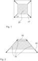
- a back plane is shown schematically, which at a first time t-1 occupies the hatched area (20, dotted line).
- the distance between the vehicle camera and the back plane has decreased, which leads to the deformation of the area (21, solid line) of the back plane in the image indicated by the arrows (d1).
- the area (20; 21) scales or enlarges as a result of the relative movement of the vehicle camera to the back plane.
- a ground plane is shown schematically, which at a first time t-1 occupies the hatched area (30, dotted line). This could be a section of a road surface on which the vehicle is driving.
- the area (in the image) changes at a subsequent time t, which leads to the deformation of the area (32) of the ground plane outlined by the arrows (d2).
- the lines marked 32 delimit the area of the ground plane.
- the "ground plane” is therefore understood here to mean a delimited area on the road surface.
- the edge area results, for example, from signatures (or edge points) on the road surface, which can be tracked in the image sequence.
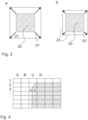
- Fig.3 illustrates the difference between a fast ( Fig. 3a : 20, 21; deformation d1) and a slowly moving ( Fig. 3b ) approaching rear wall plane (20, 23; deformation d3), if at time t-1 the rear wall plane (20) is in Fig. 3a the same Distance to the vehicle camera as the rear wall plane (20) in Fig. 3b .
- Fig.3 the difference between a close rear wall plane ( Fig. 3a : 20, 21; deformation d1) and a more distant rear wall plane (20, 23; deformation d3), which move with the same (relative) speed, then this would be in Fig. 3b object (20, 21) in real space is larger than the object in Fig. 3a represented object (20, 23).
- the vector x t 0 describes the 3D correspondence at time t-0 of the vector x t 1 at time t-1.
- a homography can be calculated image-based by knowing four point correspondences (cf. Tutorial: Multiple View Geometry, Hartley, R.
- Equation 3 shows that for an inverse TTC t / d not equal to zero, planes with different orientations n can be modeled and that planes with identical orientations n can be separated via their inverse TTC.
- H R ⁇ t ⁇ n ′ d
- a homography can theoretically be decomposed into the normal vector n, the rotation matrix R and the inverse TTC t / d . Unfortunately This decomposition is numerically extremely unstable and sensitive to measurement errors.
- Fig.4 shows a schematic of a division into cells (grid, grid/lines).
- the scene is divided into NxM initial cells and each point correspondence is assigned a unique ID.
- This ID initially indicates the affiliation to a cell. Later on, the ID can indicate the affiliation to a cluster or an object.
- An object (particularly a backplane) in the foreground is shown hatched.
- the background is shown in white. If a cell contains only one object (cells B3, D3), a homography will describe this cell very well. However, if a cell contains more than one object (cell C3), the homography will not describe either object well. If the point correspondences (black point or black cross or x) are assigned to the clusters (or segments) of the neighboring cells (B3 or D3) via their backprojection errors, the black point is assigned to the segment of cell B3 and the black cross to the segment of cell D3, since the homography for cell C3 describes neither the foreground nor the background well.
- the segment sizes can be adapted to the scene, for example by generating larger areas in the vicinity of the vehicle or in areas with a positive classification response.
- a dedicated back/ground and side plane homography is calculated, as shown in equations 5 to 10.
- x 0 c ⁇ a y 0 c ⁇ b ⁇ ⁇ x 1 0 x 1 x 0 0 ⁇ x 1 x 1 y 0 ⁇ t x t y t z or .
- x 0 c ⁇ a y 0 c ⁇ b ⁇ ⁇ 1 0 x 0 0 ⁇ 1 y 0 ⁇ t x t y t z .
- neighboring cells can be combined in a further step by calculating the backprojection errors ⁇ x t 0 i ⁇ H j x t 1 i or ⁇ x t 0 j ⁇ H i x t 1 j over support points (see below point 1. : RANSAC) of the neighboring segments j and i and their homographies. Two neighboring clusters are combined if ⁇ x t 0 i ⁇ H j x t 1 i smaller ⁇ x t 0 i ⁇ H i x t 1 i or, for example, the backprojection error normalized to the predicted flow length is below an adjustable threshold.
- two neighboring clusters can be combined if ⁇ x t 0 i ⁇ H j x t 1 i smaller ⁇ x t 0 i ⁇ H i x t 1 i and the two back projection errors ⁇ x t 0 i ⁇ H j x t 1 i and ⁇ x t 0 i ⁇ H i x t 1 i fall below a threshold normalized to the flow length.
- backprojection errors can be used as potentials in a graph and a global solution can be calculated. The compactness of the clusters can be determined using the edge potentials in the graph.
- the homographies are recalculated and the point correspondences are assigned to the clusters with the lowest backprojection error. If only directly adjacent clusters are considered, very compact objects can be generated. If the minimum error exceeds an adjustable threshold, new (cluster/object) IDs are assigned to the correspondences in order to be able to recognize partially occluded objects or objects with slightly different TTC. By setting the threshold, the resolution of (slightly) different objects can be adjusted.
- the backprojection errors can be biased to reduce costs for contiguous regions or to increase the costs of an ID change if point correspondences have had the same ID affiliation over a longer period of time.
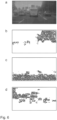
- Fig.5 shows an example of scene segmentation:
- Fig. 5a shows an image taken by a vehicle camera that is located inside the vehicle and records the area ahead through the windshield.
- a three-lane road (51) can be seen, e.g. a motorway. The lanes are separated by corresponding lane markings. Vehicles are driving in all three lanes. The vehicle driving ahead in its own lane (53) may obscure other vehicles driving ahead in its own lane.
- To the left of the three-lane road there is a raised structural barrier (52) to the oncoming lane.
- To the right of the three-lane road (51) there is a shoulder or hard shoulder, which is bordered to the right by a guardrail, behind which there is a wooded area.
- this scene can be segmented.
- Fig. 5b to 5d Cells (56) can be seen.
- Point correspondences (55) are shown in the cells.
- the assignment of a cell (56) to a segment is shown by the color of the cell frame or the point correspondences (55).
- Fig. 5b shows the red channel of the segmented image
- Fig. 5c the green channel
- Fig. 5d the blue channel.
- One segment which is green in the original, extends over the bottom five to six lines (in Fig. 5b and 5d shown in white and without a cell frame). This segment corresponds to the ground level, i.e. the surface of the road (51) on which your car is driving.
- the segmentation result shown was determined without prior knowledge of the scene in just three iteration steps. This shows the enormous speed and performance of an embodiment of the invention through temporal integration.
- Fig.6 shows a determination of the orientation of planes in the already Fig.5 described scene.
- Fig. 6a shows the surrounding situation for orientation according to Fig. 5a .
- All correspondences assigned to a side wall level show Fig. 6b .
- the correspondences on the left edge were assigned to a right side wall level, which is correct because that is where the right side of the structural boundary (52) to the opposite lane is located in the image.
- the correspondences in the right half of the image were assigned to left side wall levels, which is also correct because that is where the "left side" of the roadside buildings or plants is located in the image.
- Fig. 6c shows which correspondences are assigned to a ground plane, which is correct since the surface of the roadway (51) can be seen there in the image.
- Fig. 6d shows which correspondences are assigned to a rear wall plane. This is largely correct. From this determination alone, different rear wall planes cannot be sufficiently distinguished, eg those of the delivery truck (53) driving ahead in the same lane from the signs of the sign bridge (54) arranged above it in the image. However, this representation already provides important information about where raised objects occur in the vehicle's surroundings.
- the inverse TTC (t x , t y , t z ) can be used to detect dynamic objects.
- Fig. 7a shows the picture of the vehicle situation (identical to Fig. 6a ).
- the vehicle driving ahead in the same lane (73) is a delivery van.
- Fig. 7b shows correspondences that in turn correspond to the ground plane (violet in the original) and are the only ones with a red component.
- Fig. 7c shows correspondences that are assigned to moving objects. In the original, these are green when they are moving away from your own vehicle (i.e. driving faster) and turquoise when they are driving slower.
- Fig. 7d shows correspondences with a blue component, i.e. those that correspond to the ground plane (cf. Fig. 7b ), moving objects approaching your own vehicle (cf. Fig. 7c ) and those that correspond to static raised objects, these are only in Fig. 7d shown, such as forest areas to the left and right of the motorway and the sign bridges.
- Fig. 7c and 7d together, it can be seen that the vehicle in its own lane (73) is approaching. The same applies to the vehicle in front in the right lane (75). In contrast, the other vehicles (71, 72 and 74) are moving away.
- the area that corresponds to the sky in the image does not lead to any correspondences due to the lack of structure in the image (white in Fig. 7b to 7d ) .
- the segmentation is known at time t-1, it can be used both to predict the objects and to generate a dense flow field.
- Signature-based flow methods generate signatures and try to assign them clearly in successive frames.
- the signatures are usually calculated from a patch (image section or image area) of a defined size. However, if the size and shape of a patch change, a correspondence finding with a fixed template (pattern, pattern, for example an image section of a image of the image sequence that corresponds to an object - for example a vehicle template) is no longer possible. If you approach a back plane, for example, the size of a patch changes. Or if you move over a ground plane or parallel to a side plane, both the size and shape of a patch change, see Fig. 1 and 2 ). If the segmentation is present at time t-1, the homographies can be recalculated over already found flow vectors and used to predict the position and shape of already established correspondences from t-1 to t-0.
- the current frame at time t-0 can be transformed to time t-1 to compensate for scale and shape changes.
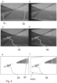
- Fig.8 illustrates such an approach.
- Fig. 8a shows an image of a different driving situation, which was recorded by the vehicle camera at a time t-1. It shows a motorway with three lanes in each direction. To the left of the three-lane road there is a guardrail (81) as a raised boundary to the oncoming lane. To the right of the road there is a noise barrier (82).
- Fig. 8b shows an image that was taken at the following time t and was transformed ("warped") via the homography of the guardrail in such a way that the changes in the image in the area of the guardrail that occur as a result of the movement of the vehicle and thus of the vehicle camera between the two recording times are compensated.
- the forward movement of the own vehicle leads to Fig. 8b that the nearest lane marking is closer to your own vehicle than in Fig. 8a
- the transformation leads to the trapezoidal displacement of the image, which in Fig. 8f is illustrated by a dashed line.
- Fig. 8c now shows corresponding features (85) which are in the area of the guard rail (81, cf. Fig. 8a ) as white dots.
- Fig. 8d shows where these corresponding features are to be expected in the next image (86), after this as to Fig. 8b has been transformed as described.
- the current image can be warped to the previous image for each segment in order to find existing correspondences that have changed in scale or shape or to establish new correspondences using congruent templates.
- the homography from the last frame can be used as an approximation to make the correspondence finding more robust against shape and scale changes.
Landscapes
- Engineering & Computer Science (AREA)
- Automation & Control Theory (AREA)
- Physics & Mathematics (AREA)
- General Physics & Mathematics (AREA)
- Multimedia (AREA)
- Theoretical Computer Science (AREA)
- Human Computer Interaction (AREA)
- Transportation (AREA)
- Mechanical Engineering (AREA)
- Image Analysis (AREA)
- Image Processing (AREA)
- Traffic Control Systems (AREA)
- Closed-Circuit Television Systems (AREA)
Applications Claiming Priority (2)
| Application Number | Priority Date | Filing Date | Title |
|---|---|---|---|
| DE102016218852.6A DE102016218852A1 (de) | 2016-09-29 | 2016-09-29 | Detektion von Objekten aus Bildern einer Kamera |
| PCT/DE2017/200102 WO2018059631A1 (de) | 2016-09-29 | 2017-09-28 | Detektion und validierung von objekten aus sequentiellen bildern einer kamera mittels homographien |
Publications (2)
| Publication Number | Publication Date |
|---|---|
| EP3520024A1 EP3520024A1 (de) | 2019-08-07 |
| EP3520024B1 true EP3520024B1 (de) | 2024-09-11 |
Family
ID=60262655
Family Applications (1)
| Application Number | Title | Priority Date | Filing Date |
|---|---|---|---|
| EP17794220.8A Active EP3520024B1 (de) | 2016-09-29 | 2017-09-28 | Detektion und validierung von objekten aus sequentiellen bildern einer kamera mittels homographien |
Country Status (7)
| Country | Link |
|---|---|
| US (1) | US10984263B2 (enExample) |
| EP (1) | EP3520024B1 (enExample) |
| JP (1) | JP7050763B2 (enExample) |
| KR (1) | KR102491527B1 (enExample) |
| CN (1) | CN109791607B (enExample) |
| DE (2) | DE102016218852A1 (enExample) |
| WO (1) | WO2018059631A1 (enExample) |
Families Citing this family (9)
| Publication number | Priority date | Publication date | Assignee | Title |
|---|---|---|---|---|
| DE102016218849A1 (de) | 2016-09-29 | 2018-03-29 | Conti Temic Microelectronic Gmbh | Detektion und Tracking von Objekten aus Bildern einer Kamera |
| DE102016218852A1 (de) * | 2016-09-29 | 2018-03-29 | Conti Temic Microelectronic Gmbh | Detektion von Objekten aus Bildern einer Kamera |
| DE102016218853A1 (de) | 2016-09-29 | 2018-03-29 | Conti Temic Microelectronic Gmbh | Detektion und Validierung von Objekten aus Bildern einer Kamera |
| US10706587B1 (en) * | 2018-09-25 | 2020-07-07 | Amazon Technologies, Inc. | Calibration of multiple cameras |
| CN111260719B (zh) * | 2020-01-09 | 2022-10-25 | 上海交通大学 | 一种基于神经网络算法的碰撞时间计算系统和方法 |
| CN113284197B (zh) * | 2021-07-22 | 2021-11-23 | 浙江华睿科技股份有限公司 | Agv的tof相机外参标定方法及装置、电子设备 |
| FR3155191A1 (fr) | 2023-11-13 | 2025-05-16 | Continental Autonomous Mobility Germany GmbH | Détection de segments |
| FR3155189A1 (fr) | 2023-11-13 | 2025-05-16 | Continental Autonomous Mobility Germany GmbH | Suivi anticipé d’objets latéraux |
| CN119705437B (zh) * | 2025-01-20 | 2025-10-03 | 重庆长安汽车股份有限公司 | 一种车辆前向碰撞预警方法、装置、设备及存储介质 |
Citations (1)
| Publication number | Priority date | Publication date | Assignee | Title |
|---|---|---|---|---|
| US20150086080A1 (en) * | 2012-12-04 | 2015-03-26 | Mobileye Vision Technologies Ltd. | Road vertical contour detection |
Family Cites Families (35)
| Publication number | Priority date | Publication date | Assignee | Title |
|---|---|---|---|---|
| JPH11353565A (ja) | 1998-06-09 | 1999-12-24 | Yazaki Corp | 車両用衝突警報方法及び装置 |
| JP3463858B2 (ja) | 1998-08-27 | 2003-11-05 | 矢崎総業株式会社 | 周辺監視装置及び方法 |
| US6618672B2 (en) | 1998-10-21 | 2003-09-09 | Yazaki Corporation | Vehicle-applied rear-and-side monitoring system |
| DE19926559A1 (de) | 1999-06-11 | 2000-12-21 | Daimler Chrysler Ag | Verfahren und Vorrichtung zur Detektion von Objekten im Umfeld eines Straßenfahrzeugs bis in große Entfernung |
| JP4118452B2 (ja) * | 1999-06-16 | 2008-07-16 | 本田技研工業株式会社 | 物体認識装置 |
| JP2002189075A (ja) * | 2000-12-20 | 2002-07-05 | Fujitsu Ten Ltd | 道路上方静止物検知方法 |
| JP3895238B2 (ja) * | 2002-08-28 | 2007-03-22 | 株式会社東芝 | 障害物検出装置及びその方法 |
| JP3987048B2 (ja) * | 2003-03-20 | 2007-10-03 | 本田技研工業株式会社 | 車両周辺監視装置 |
| DE10317044A1 (de) | 2003-04-11 | 2004-10-21 | Daimlerchrysler Ag | Freiraumüberwachung bei Kraftfahrzeugen |
| DE10351778A1 (de) | 2003-11-06 | 2005-06-09 | Daimlerchrysler Ag | Verfahren zur Korrespondenzanalyse in Bilddatensätzen |
| JP4328692B2 (ja) | 2004-08-11 | 2009-09-09 | 国立大学法人東京工業大学 | 物体検出装置 |
| DE102004046101B4 (de) | 2004-09-23 | 2007-01-18 | Daimlerchrysler Ag | Verfahren, Sicherheitsvorrichtung und Verwendung der Sicherheitsvorrichtung zur Früherkennung von Kraftfahrzeugkollisionen |
| US7130745B2 (en) | 2005-02-10 | 2006-10-31 | Toyota Technical Center Usa, Inc. | Vehicle collision warning system |
| JP4203512B2 (ja) * | 2006-06-16 | 2009-01-07 | 本田技研工業株式会社 | 車両周辺監視装置 |
| JP4166253B2 (ja) * | 2006-07-10 | 2008-10-15 | トヨタ自動車株式会社 | 物体検出装置、物体検出方法、および物体検出用プログラム |
| JP4267657B2 (ja) * | 2006-10-31 | 2009-05-27 | 本田技研工業株式会社 | 車両周辺監視装置 |
| WO2008065717A1 (fr) * | 2006-11-29 | 2008-06-05 | Fujitsu Limited | Système et procédé de détection de piéton |
| US8098889B2 (en) | 2007-01-18 | 2012-01-17 | Siemens Corporation | System and method for vehicle detection and tracking |
| JP5146446B2 (ja) * | 2007-03-22 | 2013-02-20 | 日本電気株式会社 | 移動体検知装置および移動体検知プログラムと移動体検知方法 |
| EP3594853A3 (en) * | 2007-05-03 | 2020-04-08 | Sony Deutschland GmbH | Method for detecting moving objects in a blind spot region of a vehicle and blind spot detection device |
| JP2009100342A (ja) | 2007-10-18 | 2009-05-07 | Sanyo Electric Co Ltd | カメラ校正装置及び方法、並びに、車両 |
| JP5410730B2 (ja) | 2008-10-09 | 2014-02-05 | 日立オートモティブシステムズ株式会社 | 自動車の外界認識装置 |
| DE102009028742A1 (de) | 2009-08-20 | 2011-02-24 | Robert Bosch Gmbh | Verfahren und Steuergerät zur Bestimmung einer Bewegungsinformation eines Objekts |
| US8232872B2 (en) | 2009-12-03 | 2012-07-31 | GM Global Technology Operations LLC | Cross traffic collision alert system |
| US9959595B2 (en) | 2010-09-21 | 2018-05-01 | Mobileye Vision Technologies Ltd. | Dense structure from motion |
| US9118816B2 (en) | 2011-12-06 | 2015-08-25 | Mobileye Vision Technologies Ltd. | Road vertical contour detection |
| US9251708B2 (en) | 2010-12-07 | 2016-02-02 | Mobileye Vision Technologies Ltd. | Forward collision warning trap and pedestrian advanced warning system |
| DE102011006564B4 (de) * | 2011-03-31 | 2025-08-28 | Robert Bosch Gmbh | Verfahren zur Auswertung eines von einer Kamera eines Fahrzeugs aufgenommenen Bildes und Bildaufbereitungsvorrichtung |
| EP2546804A1 (en) | 2011-07-10 | 2013-01-16 | Dürr Dental AG | Method and tomography apparatus for reconstruction of a 3D volume |
| JP5944781B2 (ja) * | 2012-07-31 | 2016-07-05 | 株式会社デンソーアイティーラボラトリ | 移動体認識システム、移動体認識プログラム、及び移動体認識方法 |
| CN112580456B (zh) | 2014-05-14 | 2025-09-02 | 御眼视觉技术有限公司 | 用于路缘检测和行人危险评估的系统和方法 |
| DE102015224796A1 (de) | 2015-12-10 | 2017-06-14 | Robert Bosch Gmbh | Verfahren und Steuergerät zum Erkennen einer möglichen Kollision eines unbemannten Luftfahrzeugs mit einem Objekt |
| DE102016218852A1 (de) * | 2016-09-29 | 2018-03-29 | Conti Temic Microelectronic Gmbh | Detektion von Objekten aus Bildern einer Kamera |
| DE102016218849A1 (de) | 2016-09-29 | 2018-03-29 | Conti Temic Microelectronic Gmbh | Detektion und Tracking von Objekten aus Bildern einer Kamera |
| DE102016218853A1 (de) | 2016-09-29 | 2018-03-29 | Conti Temic Microelectronic Gmbh | Detektion und Validierung von Objekten aus Bildern einer Kamera |
-
2016
- 2016-09-29 DE DE102016218852.6A patent/DE102016218852A1/de not_active Withdrawn
-
2017
- 2017-09-28 DE DE112017003466.3T patent/DE112017003466A5/de not_active Withdrawn
- 2017-09-28 CN CN201780060471.3A patent/CN109791607B/zh active Active
- 2017-09-28 WO PCT/DE2017/200102 patent/WO2018059631A1/de not_active Ceased
- 2017-09-28 US US16/323,826 patent/US10984263B2/en active Active
- 2017-09-28 JP JP2019513924A patent/JP7050763B2/ja active Active
- 2017-09-28 KR KR1020197005955A patent/KR102491527B1/ko active Active
- 2017-09-28 EP EP17794220.8A patent/EP3520024B1/de active Active
Patent Citations (1)
| Publication number | Priority date | Publication date | Assignee | Title |
|---|---|---|---|---|
| US20150086080A1 (en) * | 2012-12-04 | 2015-03-26 | Mobileye Vision Technologies Ltd. | Road vertical contour detection |
Non-Patent Citations (1)
| Title |
|---|
| M.I.A. LOURAKIS ET AL: "Detecting Planes In An Uncalibrated Image Pair", PROCEEDINGS OF THE 13TH BRITISH MACHINE VISION CONFERENCE : 2ND - 5TH SEPTEMBER 2002, CARDIFF UNIVERSITY, 1 January 2002 (2002-01-01), Cardiff, pages 57.1 - 57.10, XP055439691, ISBN: 978-1-901725-19-3, DOI: 10.5244/C.16.57 * |
Also Published As
| Publication number | Publication date |
|---|---|
| CN109791607A (zh) | 2019-05-21 |
| KR102491527B1 (ko) | 2023-01-20 |
| DE112017003466A5 (de) | 2019-03-21 |
| DE102016218852A1 (de) | 2018-03-29 |
| US10984263B2 (en) | 2021-04-20 |
| CN109791607B (zh) | 2024-06-04 |
| WO2018059631A1 (de) | 2018-04-05 |
| EP3520024A1 (de) | 2019-08-07 |
| JP7050763B2 (ja) | 2022-04-08 |
| KR20190059894A (ko) | 2019-05-31 |
| US20190180121A1 (en) | 2019-06-13 |
| JP2019530924A (ja) | 2019-10-24 |
Similar Documents
| Publication | Publication Date | Title |
|---|---|---|
| EP3520024B1 (de) | Detektion und validierung von objekten aus sequentiellen bildern einer kamera mittels homographien | |
| EP3520025B1 (de) | Detektion und validierung von objekten aus sequentiellen bildern einer kamera mittels homographien | |
| DE19636028C1 (de) | Verfahren zur Stereobild-Objektdetektion | |
| EP3520023B1 (de) | Detektion und validierung von objekten aus sequentiellen bildern einer kamera | |
| DE102009005553B4 (de) | Verfahren und Vorrichtung zur Erkennung der Umgebung eines Kraftfahrzeugs | |
| DE102014209137B4 (de) | Verfahren und Vorrichtung zur Kalibrierung eines Kamerasystems eines Kraftfahrzeugs | |
| DE69624980T2 (de) | Objektüberwachungsverfahren und -gerät mit zwei oder mehreren Kameras | |
| DE102019114622B4 (de) | Erfassung und planare darstellung dreidimensionaler fahrspuren in einer strassenszene | |
| DE102009009047A1 (de) | Verfahren zur Objektdetektion | |
| EP2116958B1 (de) | Verfahren und Vorrichtung zum Ermitteln des Fahrbahnverlaufs im Bereich vor einem Fahrzeug | |
| WO2013029722A2 (de) | Verfahren zur umgebungsrepräsentation | |
| DE102014112820A1 (de) | Fahrzeugaußenumgebungerkennungsvorrichtung | |
| EP2023265A1 (de) | Verfahren für eine Erkennung eines Gegenstandes | |
| DE112017007347T5 (de) | Objekterkennungsvorrichtung und fahrzeug | |
| DE102013113960A1 (de) | Fahrbahnoberflächenform-Ermittlungsvorrichtung | |
| DE102015115012A1 (de) | Verfahren zum Erzeugen einer Umgebungskarte einer Umgebung eines Kraftfahrzeugs anhand eines Bilds einer Kamera, Fahrerassistenzsystem sowie Kraftfahrzeug | |
| DE102019208216A1 (de) | Detektion, 3D-Rekonstruktion und Nachverfolgung von mehreren relativ zueinander bewegten starren Objekten | |
| DE102013012930A1 (de) | Verfahren zum Bestimmen eines aktuellen Abstands und/oder einer aktuellen Geschwindigkeit eines Zielobjekts anhand eines Referenzpunkts in einem Kamerabild, Kamerasystem und Kraftfahrzeug | |
| DE102018100909A1 (de) | Verfahren zum Rekonstruieren von Bildern einer Szene, die durch ein multifokales Kamerasystem aufgenommen werden | |
| DE102012023060A1 (de) | Verfahren zum Detektieren eines beweglichen Objekts mithilfe eines Histogramms anhand von Bildern einer Kamera und Kamerasystem für ein Kraftfahrzeug | |
| DE102012024878A1 (de) | Verfahren zum Detektieren eines Zielobjekts anhand eines Kamerabilds durch Clusterbildung aus mehreren benachbarten Bildzellen, Kameraeinrichtung und Kraftfahrzeug | |
| DE102015211871A1 (de) | Objekterkennungsvorrichtung | |
| DE102019209473A1 (de) | Verfahren und Vorrichtung zur schnellen Erfassung von sich wiederholenden Strukturen in dem Bild einer Straßenszene | |
| DE102015204529A1 (de) | Verfahren und Vorrichtung zur Objekterkennung in einem Fortbewegungsmittel | |
| WO2018059629A1 (de) | Detektion und validierung von objekten aus sequentiellen bildern einer kamera mittels homographien |
Legal Events
| Date | Code | Title | Description |
|---|---|---|---|
| STAA | Information on the status of an ep patent application or granted ep patent |
Free format text: STATUS: UNKNOWN |
|
| STAA | Information on the status of an ep patent application or granted ep patent |
Free format text: STATUS: THE INTERNATIONAL PUBLICATION HAS BEEN MADE |
|
| PUAI | Public reference made under article 153(3) epc to a published international application that has entered the european phase |
Free format text: ORIGINAL CODE: 0009012 |
|
| STAA | Information on the status of an ep patent application or granted ep patent |
Free format text: STATUS: REQUEST FOR EXAMINATION WAS MADE |
|
| 17P | Request for examination filed |
Effective date: 20190429 |
|
| AK | Designated contracting states |
Kind code of ref document: A1 Designated state(s): AL AT BE BG CH CY CZ DE DK EE ES FI FR GB GR HR HU IE IS IT LI LT LU LV MC MK MT NL NO PL PT RO RS SE SI SK SM TR |
|
| AX | Request for extension of the european patent |
Extension state: BA ME |
|
| DAV | Request for validation of the european patent (deleted) | ||
| DAX | Request for extension of the european patent (deleted) | ||
| RAP1 | Party data changed (applicant data changed or rights of an application transferred) |
Owner name: CONTI TEMIC MICROELECTRONIC GMBH |
|
| STAA | Information on the status of an ep patent application or granted ep patent |
Free format text: STATUS: EXAMINATION IS IN PROGRESS |
|
| 17Q | First examination report despatched |
Effective date: 20210309 |
|
| RAP1 | Party data changed (applicant data changed or rights of an application transferred) |
Owner name: CONTINENTAL AUTONOMOUS MOBILITY GERMANY GMBH |
|
| REG | Reference to a national code |
Ref country code: DE Free format text: PREVIOUS MAIN CLASS: G06K0009000000 Ipc: G06V0020580000 Ref country code: DE Ref legal event code: R079 Ref document number: 502017016431 Country of ref document: DE Free format text: PREVIOUS MAIN CLASS: G06K0009000000 Ipc: G06V0020580000 |
|
| GRAP | Despatch of communication of intention to grant a patent |
Free format text: ORIGINAL CODE: EPIDOSNIGR1 |
|
| STAA | Information on the status of an ep patent application or granted ep patent |
Free format text: STATUS: GRANT OF PATENT IS INTENDED |
|
| RIC1 | Information provided on ipc code assigned before grant |
Ipc: G06V 20/58 20220101AFI20240422BHEP |
|
| INTG | Intention to grant announced |
Effective date: 20240513 |
|
| GRAS | Grant fee paid |
Free format text: ORIGINAL CODE: EPIDOSNIGR3 |
|
| GRAA | (expected) grant |
Free format text: ORIGINAL CODE: 0009210 |
|
| STAA | Information on the status of an ep patent application or granted ep patent |
Free format text: STATUS: THE PATENT HAS BEEN GRANTED |
|
| AK | Designated contracting states |
Kind code of ref document: B1 Designated state(s): AL AT BE BG CH CY CZ DE DK EE ES FI FR GB GR HR HU IE IS IT LI LT LU LV MC MK MT NL NO PL PT RO RS SE SI SK SM TR |
|
| REG | Reference to a national code |
Ref country code: GB Ref legal event code: FG4D Free format text: NOT ENGLISH |
|
| REG | Reference to a national code |
Ref country code: CH Ref legal event code: EP |
|
| REG | Reference to a national code |
Ref country code: DE Ref legal event code: R096 Ref document number: 502017016431 Country of ref document: DE |
|
| REG | Reference to a national code |
Ref country code: IE Ref legal event code: FG4D Free format text: LANGUAGE OF EP DOCUMENT: GERMAN |
|
| REG | Reference to a national code |
Ref country code: LT Ref legal event code: MG9D |
|
| PG25 | Lapsed in a contracting state [announced via postgrant information from national office to epo] |
Ref country code: NO Free format text: LAPSE BECAUSE OF FAILURE TO SUBMIT A TRANSLATION OF THE DESCRIPTION OR TO PAY THE FEE WITHIN THE PRESCRIBED TIME-LIMIT Effective date: 20241211 |
|
| REG | Reference to a national code |
Ref country code: NL Ref legal event code: MP Effective date: 20240911 |
|
| PG25 | Lapsed in a contracting state [announced via postgrant information from national office to epo] |
Ref country code: GR Free format text: LAPSE BECAUSE OF FAILURE TO SUBMIT A TRANSLATION OF THE DESCRIPTION OR TO PAY THE FEE WITHIN THE PRESCRIBED TIME-LIMIT Effective date: 20241212 Ref country code: FI Free format text: LAPSE BECAUSE OF FAILURE TO SUBMIT A TRANSLATION OF THE DESCRIPTION OR TO PAY THE FEE WITHIN THE PRESCRIBED TIME-LIMIT Effective date: 20240911 |
|
| PG25 | Lapsed in a contracting state [announced via postgrant information from national office to epo] |
Ref country code: BG Free format text: LAPSE BECAUSE OF FAILURE TO SUBMIT A TRANSLATION OF THE DESCRIPTION OR TO PAY THE FEE WITHIN THE PRESCRIBED TIME-LIMIT Effective date: 20240911 |
|
| PG25 | Lapsed in a contracting state [announced via postgrant information from national office to epo] |
Ref country code: LV Free format text: LAPSE BECAUSE OF FAILURE TO SUBMIT A TRANSLATION OF THE DESCRIPTION OR TO PAY THE FEE WITHIN THE PRESCRIBED TIME-LIMIT Effective date: 20240911 |
|
| PG25 | Lapsed in a contracting state [announced via postgrant information from national office to epo] |
Ref country code: HR Free format text: LAPSE BECAUSE OF FAILURE TO SUBMIT A TRANSLATION OF THE DESCRIPTION OR TO PAY THE FEE WITHIN THE PRESCRIBED TIME-LIMIT Effective date: 20240911 |
|
| PG25 | Lapsed in a contracting state [announced via postgrant information from national office to epo] |
Ref country code: ES Free format text: LAPSE BECAUSE OF FAILURE TO SUBMIT A TRANSLATION OF THE DESCRIPTION OR TO PAY THE FEE WITHIN THE PRESCRIBED TIME-LIMIT Effective date: 20240911 Ref country code: RS Free format text: LAPSE BECAUSE OF FAILURE TO SUBMIT A TRANSLATION OF THE DESCRIPTION OR TO PAY THE FEE WITHIN THE PRESCRIBED TIME-LIMIT Effective date: 20241211 |
|
| PG25 | Lapsed in a contracting state [announced via postgrant information from national office to epo] |
Ref country code: RS Free format text: LAPSE BECAUSE OF FAILURE TO SUBMIT A TRANSLATION OF THE DESCRIPTION OR TO PAY THE FEE WITHIN THE PRESCRIBED TIME-LIMIT Effective date: 20241211 Ref country code: NO Free format text: LAPSE BECAUSE OF FAILURE TO SUBMIT A TRANSLATION OF THE DESCRIPTION OR TO PAY THE FEE WITHIN THE PRESCRIBED TIME-LIMIT Effective date: 20241211 Ref country code: LV Free format text: LAPSE BECAUSE OF FAILURE TO SUBMIT A TRANSLATION OF THE DESCRIPTION OR TO PAY THE FEE WITHIN THE PRESCRIBED TIME-LIMIT Effective date: 20240911 Ref country code: HR Free format text: LAPSE BECAUSE OF FAILURE TO SUBMIT A TRANSLATION OF THE DESCRIPTION OR TO PAY THE FEE WITHIN THE PRESCRIBED TIME-LIMIT Effective date: 20240911 Ref country code: GR Free format text: LAPSE BECAUSE OF FAILURE TO SUBMIT A TRANSLATION OF THE DESCRIPTION OR TO PAY THE FEE WITHIN THE PRESCRIBED TIME-LIMIT Effective date: 20241212 Ref country code: FI Free format text: LAPSE BECAUSE OF FAILURE TO SUBMIT A TRANSLATION OF THE DESCRIPTION OR TO PAY THE FEE WITHIN THE PRESCRIBED TIME-LIMIT Effective date: 20240911 Ref country code: ES Free format text: LAPSE BECAUSE OF FAILURE TO SUBMIT A TRANSLATION OF THE DESCRIPTION OR TO PAY THE FEE WITHIN THE PRESCRIBED TIME-LIMIT Effective date: 20240911 Ref country code: BG Free format text: LAPSE BECAUSE OF FAILURE TO SUBMIT A TRANSLATION OF THE DESCRIPTION OR TO PAY THE FEE WITHIN THE PRESCRIBED TIME-LIMIT Effective date: 20240911 |
|
| PG25 | Lapsed in a contracting state [announced via postgrant information from national office to epo] |
Ref country code: NL Free format text: LAPSE BECAUSE OF FAILURE TO SUBMIT A TRANSLATION OF THE DESCRIPTION OR TO PAY THE FEE WITHIN THE PRESCRIBED TIME-LIMIT Effective date: 20240911 |
|
| PG25 | Lapsed in a contracting state [announced via postgrant information from national office to epo] |
Ref country code: PT Free format text: LAPSE BECAUSE OF FAILURE TO SUBMIT A TRANSLATION OF THE DESCRIPTION OR TO PAY THE FEE WITHIN THE PRESCRIBED TIME-LIMIT Effective date: 20250113 Ref country code: IS Free format text: LAPSE BECAUSE OF FAILURE TO SUBMIT A TRANSLATION OF THE DESCRIPTION OR TO PAY THE FEE WITHIN THE PRESCRIBED TIME-LIMIT Effective date: 20250111 |
|
| PG25 | Lapsed in a contracting state [announced via postgrant information from national office to epo] |
Ref country code: RO Free format text: LAPSE BECAUSE OF FAILURE TO SUBMIT A TRANSLATION OF THE DESCRIPTION OR TO PAY THE FEE WITHIN THE PRESCRIBED TIME-LIMIT Effective date: 20240911 Ref country code: SM Free format text: LAPSE BECAUSE OF FAILURE TO SUBMIT A TRANSLATION OF THE DESCRIPTION OR TO PAY THE FEE WITHIN THE PRESCRIBED TIME-LIMIT Effective date: 20240911 |
|
| PG25 | Lapsed in a contracting state [announced via postgrant information from national office to epo] |
Ref country code: EE Free format text: LAPSE BECAUSE OF FAILURE TO SUBMIT A TRANSLATION OF THE DESCRIPTION OR TO PAY THE FEE WITHIN THE PRESCRIBED TIME-LIMIT Effective date: 20240911 |
|
| PG25 | Lapsed in a contracting state [announced via postgrant information from national office to epo] |
Ref country code: CZ Free format text: LAPSE BECAUSE OF FAILURE TO SUBMIT A TRANSLATION OF THE DESCRIPTION OR TO PAY THE FEE WITHIN THE PRESCRIBED TIME-LIMIT Effective date: 20240911 Ref country code: PL Free format text: LAPSE BECAUSE OF FAILURE TO SUBMIT A TRANSLATION OF THE DESCRIPTION OR TO PAY THE FEE WITHIN THE PRESCRIBED TIME-LIMIT Effective date: 20240911 |
|
| PG25 | Lapsed in a contracting state [announced via postgrant information from national office to epo] |
Ref country code: IT Free format text: LAPSE BECAUSE OF FAILURE TO SUBMIT A TRANSLATION OF THE DESCRIPTION OR TO PAY THE FEE WITHIN THE PRESCRIBED TIME-LIMIT Effective date: 20240911 Ref country code: SK Free format text: LAPSE BECAUSE OF FAILURE TO SUBMIT A TRANSLATION OF THE DESCRIPTION OR TO PAY THE FEE WITHIN THE PRESCRIBED TIME-LIMIT Effective date: 20240911 |
|
| REG | Reference to a national code |
Ref country code: CH Ref legal event code: PL |
|
| PG25 | Lapsed in a contracting state [announced via postgrant information from national office to epo] |
Ref country code: LU Free format text: LAPSE BECAUSE OF NON-PAYMENT OF DUE FEES Effective date: 20240928 |
|
| REG | Reference to a national code |
Ref country code: DE Ref legal event code: R097 Ref document number: 502017016431 Country of ref document: DE |
|
| PG25 | Lapsed in a contracting state [announced via postgrant information from national office to epo] |
Ref country code: MC Free format text: LAPSE BECAUSE OF FAILURE TO SUBMIT A TRANSLATION OF THE DESCRIPTION OR TO PAY THE FEE WITHIN THE PRESCRIBED TIME-LIMIT Effective date: 20240911 |
|
| PG25 | Lapsed in a contracting state [announced via postgrant information from national office to epo] |
Ref country code: DK Free format text: LAPSE BECAUSE OF FAILURE TO SUBMIT A TRANSLATION OF THE DESCRIPTION OR TO PAY THE FEE WITHIN THE PRESCRIBED TIME-LIMIT Effective date: 20240911 |
|
| REG | Reference to a national code |
Ref country code: BE Ref legal event code: MM Effective date: 20240930 |
|
| REG | Reference to a national code |
Ref country code: DE Ref legal event code: R081 Ref document number: 502017016431 Country of ref document: DE Owner name: AUMOVIO AUTONOMOUS MOBILITY GERMANY GMBH, DE Free format text: FORMER OWNER: CONTINENTAL AUTONOMOUS MOBILITY GERMANY GMBH, 85057 INGOLSTADT, DE |
|
| PG25 | Lapsed in a contracting state [announced via postgrant information from national office to epo] |
Ref country code: BE Free format text: LAPSE BECAUSE OF NON-PAYMENT OF DUE FEES Effective date: 20240930 |
|
| PLBE | No opposition filed within time limit |
Free format text: ORIGINAL CODE: 0009261 |
|
| STAA | Information on the status of an ep patent application or granted ep patent |
Free format text: STATUS: NO OPPOSITION FILED WITHIN TIME LIMIT |
|
| PG25 | Lapsed in a contracting state [announced via postgrant information from national office to epo] |
Ref country code: CH Free format text: LAPSE BECAUSE OF NON-PAYMENT OF DUE FEES Effective date: 20240930 |
|
| PG25 | Lapsed in a contracting state [announced via postgrant information from national office to epo] |
Ref country code: IE Free format text: LAPSE BECAUSE OF NON-PAYMENT OF DUE FEES Effective date: 20240928 |
|
| RAP4 | Party data changed (patent owner data changed or rights of a patent transferred) |
Owner name: AUMOVIO AUTONOMOUS MOBILITY GERMANY GMBH |
|
| 26N | No opposition filed |
Effective date: 20250612 |
|
| GBPC | Gb: european patent ceased through non-payment of renewal fee |
Effective date: 20241211 |
|
| PG25 | Lapsed in a contracting state [announced via postgrant information from national office to epo] |
Ref country code: SE Free format text: LAPSE BECAUSE OF FAILURE TO SUBMIT A TRANSLATION OF THE DESCRIPTION OR TO PAY THE FEE WITHIN THE PRESCRIBED TIME-LIMIT Effective date: 20240911 |
|
| PGFP | Annual fee paid to national office [announced via postgrant information from national office to epo] |
Ref country code: DE Payment date: 20250930 Year of fee payment: 9 |
|
| PG25 | Lapsed in a contracting state [announced via postgrant information from national office to epo] |
Ref country code: GB Free format text: LAPSE BECAUSE OF NON-PAYMENT OF DUE FEES Effective date: 20241211 |
|
| PGFP | Annual fee paid to national office [announced via postgrant information from national office to epo] |
Ref country code: FR Payment date: 20250922 Year of fee payment: 9 |
|
| REG | Reference to a national code |
Ref country code: AT Ref legal event code: MM01 Ref document number: 1723378 Country of ref document: AT Kind code of ref document: T Effective date: 20240928 |