EP3519908B1 - Hlk-aktuator mit heizvorrichtung - Google Patents
Hlk-aktuator mit heizvorrichtung Download PDFInfo
- Publication number
- EP3519908B1 EP3519908B1 EP17765391.2A EP17765391A EP3519908B1 EP 3519908 B1 EP3519908 B1 EP 3519908B1 EP 17765391 A EP17765391 A EP 17765391A EP 3519908 B1 EP3519908 B1 EP 3519908B1
- Authority
- EP
- European Patent Office
- Prior art keywords
- condensation
- controller
- hvac actuator
- heating apparatus
- humidity
- Prior art date
- Legal status (The legal status is an assumption and is not a legal conclusion. Google has not performed a legal analysis and makes no representation as to the accuracy of the status listed.)
- Active
Links
Images


Classifications
-
- F—MECHANICAL ENGINEERING; LIGHTING; HEATING; WEAPONS; BLASTING
- F24—HEATING; RANGES; VENTILATING
- F24F—AIR-CONDITIONING; AIR-HUMIDIFICATION; VENTILATION; USE OF AIR CURRENTS FOR SCREENING
- F24F13/00—Details common to, or for air-conditioning, air-humidification, ventilation or use of air currents for screening
- F24F13/22—Means for preventing condensation or evacuating condensate
-
- F—MECHANICAL ENGINEERING; LIGHTING; HEATING; WEAPONS; BLASTING
- F24—HEATING; RANGES; VENTILATING
- F24F—AIR-CONDITIONING; AIR-HUMIDIFICATION; VENTILATION; USE OF AIR CURRENTS FOR SCREENING
- F24F13/00—Details common to, or for air-conditioning, air-humidification, ventilation or use of air currents for screening
- F24F13/22—Means for preventing condensation or evacuating condensate
- F24F2013/221—Means for preventing condensation or evacuating condensate to avoid the formation of condensate, e.g. dew
-
- F—MECHANICAL ENGINEERING; LIGHTING; HEATING; WEAPONS; BLASTING
- F24—HEATING; RANGES; VENTILATING
- F24F—AIR-CONDITIONING; AIR-HUMIDIFICATION; VENTILATION; USE OF AIR CURRENTS FOR SCREENING
- F24F2140/00—Control inputs relating to system states
- F24F2140/30—Condensation of water from cooled air
-
- F—MECHANICAL ENGINEERING; LIGHTING; HEATING; WEAPONS; BLASTING
- F24—HEATING; RANGES; VENTILATING
- F24F—AIR-CONDITIONING; AIR-HUMIDIFICATION; VENTILATION; USE OF AIR CURRENTS FOR SCREENING
- F24F2221/00—Details or features not otherwise provided for
- F24F2221/34—Heater, e.g. gas burner, electric air heater
Definitions
- the present invention relates to an HVAC actuator and a method to operate an HVAC actuator, in particular, an HVAC actuator with a heating apparatus.
- HVAC actuators are used to control HVAC devices, such as dampers, blend doors or valves for example.
- Accurate control of the HVAC devices is important for ensuring thermal comfort as well as achieving energy efficiency. Accordingly, accurate control is in particular required for the HVAC actuators configured to drive and regulate mechanical HVAC devices.
- HVAC actuators often feature position or speed sensors for providing information about the position or speed of drive components of the HVAC actuator, such as the motor or the drive unit, which information is used to control, for example, the motion of an output shaft of the HVAC actuator.
- reliable control of the HVAC actuator is also important with regards to safety issues, when HVAC actuators are used for fire or smoke dampers, for example.
- the HVAC actuators are usually exposed to strongly varying environmental conditions of operation, such as varying temperature, air humidity and/or pressure.
- the varying environmental conditions can have serious impacts on the performance of the HVAC actuators, as the performance of bearings, motor resistance or frictional forces in general, for example, may significantly change with the environmental conditions.
- varying temperature in connection with air humidity can lead to condensation inside the housing of the HVAC actuator, negatively affecting the components of the HVAC actuator, both, in terms of accurate control and decreased durability, e.g. due to corrosion.
- a varying performance and behavior of HVAC actuator components can lead to a decrease in energy efficiency because of an increase in power consumption of actuator components.
- JP H 10 61809 A relates to heater and a thermostat to prevent the increase of temperature in a containing case to a value higher than a specified temperature and the occurrence of dew condensation through ON and OFF of energization to the heater through self-actuated control arranged in the containing.
- JP H 11 230 396 A relates to an air conditioning ball valve using an actuator.
- a PTC heater is fitted in a case at the air conditioning ball valve side near an output shaft.
- the PTC heater is electrified by a power source so as to generate the heat, the atmospheric temperature is heated to the predetermined temperature (40-50 deg.C) by a self-temperature- control mechanism.
- JP 2006 112501 A relates to an actuator for the valve drives an electric motor to open/close a valve element of the valve.
- a resistor connected with a power supply line to the electric motor is made contact with or made adjacent to a support plate supporting the electric motor, and heat generated from the resistor is released on the surface of the support plate to prevent moisture condensation.
- CN 202 421 923 U relates to a moistureproof terminal box heating device with a clotted-dew controller, comprising a temperature sensor, a clotted-dew sensor, a temperature controller, a humidity controller and a heater, wherein the temperature sensor and the clotted-dew sensor are respectively arranged in a terminal box, a heat energy output end of the heater is connected with the terminal box, and the temperature/humidity controllers control working conditions of the heater according to information fed back by the temperature/humidity sensors.
- an HVAC actuator comprising: a motor; a motor controller coupled to the motor; and a heating apparatus thermally coupled to the HVAC actuator, wherein the HVAC actuator further comprises a condensation controller coupled to the heating apparatus, the condensation controller being configured to monitor at least one condensation parameter, and to control the heating apparatus using the at least one condensation parameter, wherein the HVAC actuator further comprises a sensing device comprising a humidity sensor configured to detect humidity as a first condensation parameter, and a temperature sensor configured to detect temperature as a second condensation parameter, wherein the HVAC actuator further comprises a memory unit configured to store a set of condensation thresholds, wherein the condensation controller is configured to select a condensation threshold from the set of condensation thresholds using the temperature detected by the temperature sensor as the second condensation parameter, the condensation threshold indicating a critical humidity, and wherein the condensation controller is configured to compare the humidity detected by the humidity sensor as the first condensation parameter to the condensation threshold, and to control the heating apparatus using the first condensation parameter and the condensation threshold to avoid condensation inside the HVAC actuator.
- the HVAC actuator further comprises a condensation controller coupled to the heating apparatus,
- this object is further achieved by a method of operating an HVAC actuator comprising a motor, a motor controller coupled to the motor, and a heating apparatus thermally coupled to the HVAC actuator, the method comprising: monitoring, by a condensation controller of the HVAC actuator, of at least one condensation parameter including detecting humidity as a first condensation parameter and detecting temperature as a second condensation parameter by a humidity sensor respectively by a temperature sensor of a sensing device of the HVAC actuator; selecting, by the condensation controller using the temperature detected by the temperature sensor as the second condensation parameter, a condensation threshold indicating a critical humidity from a set of condensation thresholds stored in a memory unit of the HVAC actuator; comparing, by the condensation controller, the humidity detected by the humidity sensor as the first condensation parameter to the condensation threshold; and controlling the heating apparatus, by the condensation controller, using the first condensation parameter and the condensation threshold to avoid condensation inside the HVAC actuator.
- the object is achieved by an HVAC actuator, comprising: a motor; a motor controller coupled to the motor; and a heating apparatus thermally coupled to the HVAC actuator.
- the HVAC actuator further comprises a condensation controller coupled to the heating apparatus; the condensation controller being configured to monitor the condensation parameters, and to control the heating apparatus using the condensation parameters.
- the condensation parameters have an influence on condensation inside the housing of the HVAC actuator. Having the sensing device integrated in the HVAC actuator has the advantage that the HVAC actuator can determine condensation parameters by itself, without extensive additional add-ons or extensions. Further, by placing the sensing device in the vicinity of the HVAC actuator components, especially inside the housing of the HVAC actuator, the local ambient conditions affecting the HVAC actuator components in a relevant manner can be reliably determined. Because of the small size of available humidity sensors, their integration into HVAC actuators does not require significant and expensive modifications of the structure of the HVAC actuators.
- the humidity sensor is a capacitive humidity sensor.
- Capacitive humidity sensors are advantageous because of their precision, small size, as well as energy efficiency, such that integration into HVAC actuators may be easily achieved.
- the condensation controller is configured to compare the at least one condensation parameter with a condensation threshold, and to control the heating apparatus using the at least one condensation parameter and the condensation threshold.
- the condensation threshold may typically be related to the dew point inside the housing of the HVAC actuator.
- the defined condensation threshold may further be related to properties such as tolerance values of the HVAC actuator components.
- the HVAC actuator further comprises a memory unit configured to store condensation thresholds.
- the condensation controller is configured to select the condensation threshold using the condensation parameter. Using a particular monitored condensation parameter, the condensation controller selects a particular condensation threshold from a set of condensation thresholds stored in the memory unit; the selected condensation threshold corresponding to the particular, current condensation parameter that reflects the instantaneous environmental condition, such as the humidity. In an embodiment, the condensation controller is configured to control the heating apparatus by turning on the heating apparatus, turning off the heating apparatus, and/or increasing the heating power of the heating apparatus.
- the condensation controller is configured to generate the condensation threshold indicating a critical humidity.
- FIG. 1 shows a block diagram of an embodiment of an HVAC actuator 1.
- a heater 14 is arranged inside the HVAC actuator 1 and thermally coupled to a drive unit 11, a motor 12, and a motor controller 13; the thermal coupling is symbolized by double lines. Further thermal couplings to further (not illustrated) components of the HVAC actuator 1 are indicated by two additional double lines.
- the heater 14 may be a resistive or an inductive heater. Alternatively, the heater 14 may be implemented by exploiting the currents in the coils of the motor.
- the heater 14 may be coupled to a printed circuit board (PCB) arranged inside the HVAC actuator 1. Additionally, the heater 14 may feature a variable heating power.
- the HVAC actuator 1 may comprise additional heaters, thermally coupled to components of the HVAC actuator 1.
- the motor 12 is operatively coupled to the drive unit 11.
- the motor controller 13 is coupled to the motor 12.
- the heater 14 is coupled to a condensation controller 15, as indicated by the double arrow.
- the condensation controller 15 controls the heating apparatus 14, for example for turning the heater 14 on or off, or to increase or decrease the heating power.
- the condensation controller 15 and the motor controller 13 may be integrated in a central controller unit (not illustrated).
- the condensation controller 15 may comprise electronic circuitry with components such as for example (programmed) microprocessors, microcontrollers, ASICs or discrete electronic components.
- the condensation controller 15 is configured to monitor at least one condensation parameter and to control the heater 14 using the at least one condensation parameter.
- the condensation controller 15 is coupled to a memory unit 16, such that condensation thresholds stored in the memory unit 16 can be accessed by the condensation controller 15.
- the memory unit 16 may further store other data or signals such as, for example, detected condensation parameters or commands for the heater 14.
- the memory unit 16 may be integrated into the condensation controller 15. Alternatively, the memory unit 16 may be part of a memory of the motor controller 13.
- the condensation controller 15 is further coupled to a sensing device 17 from which the condensation controller 15 obtains (reads out) condensation parameters.
- the sensing device 17 comprises a humidity sensor 171 and a temperature sensor 172.
- the condensation parameters read from the sensing device 17 includes the humidity detected by the humidity sensor 171 and/or the temperature detected by the temperature sensor 172.
- the sensing device 17 comprises further sensors, as indicated by the dotted line in Figure 1 .
- the sensing device 17 may be read out by the condensation controller 15 continuously or periodically with a certain rate.
- the sensing device 17 may be periodically read out by the condensation controller 15 after each heating command sent to the heater 14 by the condensation controller 15. This has the advantage that the HVAC actuator 1 may be adjusted continuously to the environmental conditions, for avoiding the components to be negatively affected by condensation.
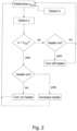
- FIG. 2 shows a flow diagram for operating the HVAC actuator 1 illustrated in Fig-ure 1 .
- a condensation threshold is defined.
- the condensation threshold is expressed by a critical humidity ⁇ crit which is determined by the condensation controller 15 using the temperature ⁇ detected by the temperature sensor 172.
- the critical humidity ⁇ crit is determined as follows: The condensation controller 15 accesses the memory unit 16 which has stored therein a set of critical humidity values ⁇ crit ( ⁇ ) which depend on the temperature ⁇ .
- the condensation controller 15 selects the critical humidity ⁇ crit corresponding to the detected temperature ⁇ .
- the critical humidity values ⁇ crit ( ⁇ ) are typically related to the dew point and to properties of the components of the HVAC actuator 1.
- the humidity ⁇ is detected using the humidity sensor 171.
- the condensation controller 15 compares the humidity ⁇ to the critical humidity ⁇ crit .
- the humidity ⁇ is in a range where condensation can have a detrimental effect to components of the HVAC actuator 1.
- the condensation controller 15 may comprise a comparator.
- the condensation controller 15 monitors whether the heater 14 is turned on or off.
- the condensation controller 15 may monitor the heating power of the heater 14.
- different commands such as turning on, turning off the heater 14 or increasing the heating power are triggered.
- the humidity ⁇ is smaller than the critical humidity ⁇ crit
- the heater 14 is turned off, if the heater 14 was turned on; or the heater 14 is left idle, if the heater 14 was already turned off.
- the heater 14 is turned on, if the heater 14 was turned off; or the heating power is increased, if the heater 14 was already turned on. After controlling the heater 14, operation returns to the step of determining the critical humidity ⁇ crit . After monitoring and controlling the heater 14, the environmental conditions, especially inside the housing of the HVAC actuator 1, have typically changed, such that the condensation controller 15 may start again with determining the condensation threshold and monitoring the at least one condensation parameter.
- Figure 3 shows a diagram with different ranges of heater controls as a function of the temperature ⁇ , the dew point and in dependence of the humidity ⁇ , based on the Magnus Formula. Sloped lines indicate the relative humidity, of which three exemplary values are labeled in Figure 3 .
- the temperature ⁇ indicates the dew point.
- the dew point inside the housing of the HVAC actuator may be determined.
- a condensation threshold may be defined. The defined condensation threshold may be such that the temperature ⁇ may be greater than the dew point by an amount for which condensation is safely avoided.
- the heater 14 is set to be always on, below a temperature ⁇ of 10°C. Above a temperature ⁇ of 30°C, the heater 14 is always set to be off. In between, the heater 14 is turned on, if the relative humidity exceeds a value of 65%.
- the critical humidity ⁇ crit for this temperature range is therefore 65%. In other embodiments, other ranges with other values of the critical humidity ⁇ crit may be defined. For example, below a temperature of 15°C, the heater 14 may be set to be turned on as soon as the relative humidity exceeds 45%. Above a temperature of 25°C, the heater 14 may be set to be turned on, as soon as the relative humidity exceeds 80%.
- the heater 14 may be turned on, if the relative humidity exceeds 60%.
- Diagrams such as the one shown in Figure 3 with ranges and values of condensation thresholds, may be stored in the memory unit 16 for example as tables or as functions and retrieved by the condensation controller 15.
- condensation controller 15 By using the condensation controller 15 according to the described method, a smart and reliable heating method for adapting to varying environmental conditions, especially for avoiding detrimental condensation inside the housing of the HVAC actuator 1, may be achieved.
- the method has the particular advantage that an avoidance of condensation may be achieved without requiring a user of the HVAC actuator 1 being active, i.e. without additional external intervention, for example for controlling the heater 14.
Landscapes
- Engineering & Computer Science (AREA)
- Chemical & Material Sciences (AREA)
- Combustion & Propulsion (AREA)
- Mechanical Engineering (AREA)
- General Engineering & Computer Science (AREA)
- Air Conditioning Control Device (AREA)
Claims (5)
- Ein HVAC-Aktor (1), umfassend:einen Motor (12);eine Motorsteuerung (13), die mit dem Motor (12) gekoppelt ist; undeine Heizvorrichtung (14), die thermisch gekoppelt ist mit dem HVAC-Aktor (1)wobei der HVAC-Aktor (1) ferner eine Kondensationssteuerung (15) umfasst, die mit der Heizvorrichtung (14) gekoppelt ist, wobei die Kondensationssteuerung (15) so konfiguriert ist, dass sie mindestens einen Kondensationsparameter überwacht und die Heizvorrichtung (14) unter Verwendung des mindestens einen Kondensationsparameters steuert,wobei der HVAC-Aktor (1) ferner eine Sensorvorrichtung (17) umfasst, die einen Feuchtigkeitssensor (171) umfasst, der konfiguriert ist, Feuchtigkeit als einen ersten Kondensationsparameter zu erfassen, und einen Temperatursensor (172) umfasst, der konfiguriert ist, Temperatur als einen zweiten Kondensationsparameter zu erfassen,wobei der HVAC-Aktor (1) ferner eine Speichereinheit (16) umfasst, die konfiguriert ist, einen Satz von Kondensationsschwellenwerten zu speichern,wobei die Kondensationssteuerung (15) so konfiguriert ist, dass sie einen Kondensationsschwellenwert aus dem Satz von Kondensationsschwellenwerten auswählt unter Verwendung der vom Temperatursensor (172) erfassten Temperatur als zweiten Kondensationsparameter, wobei der Kondensationsschwellenwert eine kritische Feuchtigkeit anzeigt, undwobei die Kondensationssteuerung (15) so konfiguriert ist, dass sie die von dem Feuchtigkeitssensor (171) erfasste Feuchtigkeit als ersten Kondensationsparameter mit dem Kondensationsschwellenwert vergleicht und die Heizvorrichtung (14) unter Verwendung des ersten Kondensationsparameters und des Kondensationsschwellenwerts steuert, um eine Kondensation im Inneren des HVAC-Aktors (1) zu vermeiden.
- HVAC-Aktor (1) gemäss Anspruch 1, wobei der Feuchtigkeitssensor (171) ein kapazitiver Feuchtigkeitssensor ist.
- HVAC-Aktor (1) gemäss einem der Ansprüche 1 oder 2, wobei die Kondensationssteuerung (15) so konfiguriert ist, dass sie die Heizvorrichtung (14) steuert, indem sie mindestens einen der folgenden Schritte ausführt: Einschalten der Heizvorrichtung (14), Ausschalten der Heizvorrichtung (14) und Erhöhen einer Heizleistung der Heizvorrichtung (14).
- Verfahren zum Betreiben eines HVAC-Aktors (1), der einen Motor (12), eine mit dem Motor (12) gekoppelte Motorsteuerung (13) und eine thermisch mit dem HVAC-Aktor (1) gekoppelte Heizvorrichtung (14) umfasst, das Verfahren umfassend:Überwachung mindestens eines Kondensationsparameters durch eine Kondensationssteuerung (15) des HVAC-Aktors (1), beinhaltend die Erfassung der Feuchtigkeit als einen ersten Kondensationsparameter und die Erfassung der Temperatur als einen zweiten Kondensationsparameter durch einen Feuchtigkeitssensor (171) respektive durch einen Temperatursensor (172) einer Sensorvorrichtung (17) des HVAC-Aktors (1);Auswahl eines Kondensationsschwellenwerts, der eine kritische Feuchtigkeit anzeigt, aus einem Satz von Kondensationsschwellenwerten, die in einer Speichereinheit (16) des HVAC-Aktors (1) gespeichert sind, durch die Kondensationssteuerung (15) unter Verwendung der von dem Temperatursensor (172) erfassten Temperatur als zweiten Kondensationsparameter;Vergleichen der von dem Feuchtigkeitssensor (171) erfassten Feuchtigkeit als ersten Kondensationsparameter mit dem Kondensationsschwellenwert durch die Kondensationssteuerung (15); undSteuerung der Heizvorrichtung (14) durch die Kondensationssteuerung (15) unter Verwendung des ersten Kondensationsparameters und des Kondensationsschwellenwertes, um eine Kondensation innerhalb des HVAC-Aktors (1) zu vermeiden.
- Verfahren gemäss Anspruch 4, wobei die Kondensationssteuerung (15) die Heizvorrichtung (14) steuert, indem sie mindestens einen der folgenden Schritte ausführt: Einschalten der Heizvorrichtung (14), Ausschalten der Heizvorrichtung (14) und Erhöhen einer Heizleistung der Heizvorrichtung (14).
Applications Claiming Priority (2)
| Application Number | Priority Date | Filing Date | Title |
|---|---|---|---|
| CH12922016 | 2016-09-30 | ||
| PCT/EP2017/072185 WO2018059883A1 (en) | 2016-09-30 | 2017-09-05 | Hvac actuator with heating apparatus |
Publications (2)
| Publication Number | Publication Date |
|---|---|
| EP3519908A1 EP3519908A1 (de) | 2019-08-07 |
| EP3519908B1 true EP3519908B1 (de) | 2025-05-07 |
Family
ID=57120969
Family Applications (1)
| Application Number | Title | Priority Date | Filing Date |
|---|---|---|---|
| EP17765391.2A Active EP3519908B1 (de) | 2016-09-30 | 2017-09-05 | Hlk-aktuator mit heizvorrichtung |
Country Status (4)
| Country | Link |
|---|---|
| US (1) | US11530838B2 (de) |
| EP (1) | EP3519908B1 (de) |
| CN (1) | CN110023869A (de) |
| WO (1) | WO2018059883A1 (de) |
Families Citing this family (2)
| Publication number | Priority date | Publication date | Assignee | Title |
|---|---|---|---|---|
| CN111102731B (zh) * | 2019-12-24 | 2021-05-04 | 珠海格力电器股份有限公司 | 一种防凝露控制方法、装置及空调设备 |
| CN113568445B (zh) * | 2021-07-21 | 2023-05-19 | 南京牧镭激光科技股份有限公司 | 一种三维扫描式测风激光雷达扫描头结露点控制装置及方法 |
Citations (1)
| Publication number | Priority date | Publication date | Assignee | Title |
|---|---|---|---|---|
| CN202421923U (zh) * | 2011-12-09 | 2012-09-05 | 台前县供电局 | 一种设有凝露控制器的端子箱防潮加热装置 |
Family Cites Families (18)
| Publication number | Priority date | Publication date | Assignee | Title |
|---|---|---|---|---|
| JPH0762550B2 (ja) * | 1986-12-26 | 1995-07-05 | 株式会社東芝 | 空気調和機 |
| JPH1061809A (ja) * | 1996-08-19 | 1998-03-06 | Shimadzu Corp | 電動バルブアクチュエータ |
| JPH11230396A (ja) * | 1998-02-13 | 1999-08-27 | Kitz Corp | アクチュエータ |
| US6470696B1 (en) * | 2001-09-18 | 2002-10-29 | Valerie Palfy | Devices and methods for sensing condensation conditions and for removing condensation from surfaces |
| JP4707990B2 (ja) * | 2004-10-14 | 2011-06-22 | 株式会社キッツ | バルブ用アクチュエータの制御方法 |
| US20140045419A1 (en) * | 2008-04-21 | 2014-02-13 | Joseph J. Bartmann | Window condensation control |
| EP2508055A4 (de) * | 2009-11-30 | 2017-05-03 | Emerson Network Power Energy Systems, North America, Inc. | Gehäuse für elektronische ausseneinheiten und entsprechende verfahren |
| US10473344B2 (en) * | 2011-03-10 | 2019-11-12 | Carrier Corporation | Electric re-heat dehumidification |
| US8783283B2 (en) * | 2012-01-31 | 2014-07-22 | Control Components, Inc. | Heating device for valve to prevent internal accumulation of condensate |
| US9410752B2 (en) * | 2012-08-17 | 2016-08-09 | Albert Reid Wallace | Hydronic building systems control |
| CN103235621B (zh) | 2013-04-28 | 2015-03-11 | 成都思晗科技有限公司 | 一种柜体用防凝露智能控制系统 |
| CN103398570B (zh) | 2013-07-19 | 2015-12-09 | 华为技术有限公司 | 设备除湿的方法、凝露检测装置和设备 |
| CN103441433B (zh) * | 2013-08-20 | 2016-06-01 | 长沙市蓝虹电气技术有限公司 | 柜体除湿装置、方法及其柜体监控系统和方法 |
| US20150064639A1 (en) * | 2013-09-05 | 2015-03-05 | Tempest Lighting, Inc. | Systems and methods for controlling the internal environment of an enclosure |
| WO2015079673A1 (ja) * | 2013-11-26 | 2015-06-04 | パナソニックIpマネジメント株式会社 | 給排型換気装置 |
| US10393395B1 (en) * | 2015-05-07 | 2019-08-27 | Aamzon Technologies, Inc. | Ice melting louver |
| CN104949434A (zh) | 2015-05-29 | 2015-09-30 | 青岛海尔科技有限公司 | 用于制冷设备透明门的除凝露方法及装置、制冷设备 |
| CN204942092U (zh) | 2015-08-11 | 2016-01-06 | 昆山俊润通风降温设备有限公司 | 排风风机 |
-
2017
- 2017-09-05 CN CN201780058029.7A patent/CN110023869A/zh active Pending
- 2017-09-05 EP EP17765391.2A patent/EP3519908B1/de active Active
- 2017-09-05 WO PCT/EP2017/072185 patent/WO2018059883A1/en not_active Ceased
- 2017-09-05 US US16/316,217 patent/US11530838B2/en active Active
Patent Citations (1)
| Publication number | Priority date | Publication date | Assignee | Title |
|---|---|---|---|---|
| CN202421923U (zh) * | 2011-12-09 | 2012-09-05 | 台前县供电局 | 一种设有凝露控制器的端子箱防潮加热装置 |
Also Published As
| Publication number | Publication date |
|---|---|
| EP3519908A1 (de) | 2019-08-07 |
| US11530838B2 (en) | 2022-12-20 |
| WO2018059883A1 (en) | 2018-04-05 |
| CN110023869A (zh) | 2019-07-16 |
| US20190309983A1 (en) | 2019-10-10 |
Similar Documents
| Publication | Publication Date | Title |
|---|---|---|
| US10001291B2 (en) | Two mode thermostat with set-back temperature and humidity set-point feature | |
| US10317862B2 (en) | Systems and methods for heat rise compensation | |
| CA2825386C (en) | Apparatus and method for control of a thermostat | |
| US7446494B2 (en) | HVAC actuator having torque compensation | |
| US4302663A (en) | Control system for a heater | |
| US20120230661A1 (en) | Apparatus and Method for Control of a Thermostat | |
| US8944099B2 (en) | Valve arrangement and method for operating a valve | |
| US7962250B2 (en) | Control method for cooling an industrial plant | |
| EP3519908B1 (de) | Hlk-aktuator mit heizvorrichtung | |
| US20190277525A1 (en) | Systems and methods for heat rise compensation | |
| US10961958B2 (en) | Humidity detection device | |
| CN107388416A (zh) | 空调室外机及其控制方法 | |
| EP3648544B1 (de) | Systeme und verfahren zur passiven erwärmung von temperaturempfindlichen elektronischen komponenten | |
| US20160258639A1 (en) | Energy harvesting damper control and method of operation | |
| CN101505026A (zh) | 对接连接器 | |
| US20110095621A1 (en) | Power Cord with Thermal Control | |
| CN1144554A (zh) | 控制电子设备内风扇电压的方法 | |
| US11809152B2 (en) | Electronic air pressure interlock switch | |
| CN104238591A (zh) | 通过温度模型对用电器的控制 | |
| CN113623841B (zh) | 空调控制方法和空调器 | |
| CN104375540B (zh) | 硬盘录像设备的内部温度控制方法 | |
| US20170184321A1 (en) | System and method for operating a variable speed compressor | |
| JP2014161471A (ja) | ミストサウナ装置 | |
| CN112969892A (zh) | 用于流量调节阀的自动调节式设定装置和用于自动调节式设定的方法 | |
| EP2226698A2 (de) | Thermostat für Haushaltsgeräte |
Legal Events
| Date | Code | Title | Description |
|---|---|---|---|
| STAA | Information on the status of an ep patent application or granted ep patent |
Free format text: STATUS: UNKNOWN |
|
| STAA | Information on the status of an ep patent application or granted ep patent |
Free format text: STATUS: THE INTERNATIONAL PUBLICATION HAS BEEN MADE |
|
| PUAI | Public reference made under article 153(3) epc to a published international application that has entered the european phase |
Free format text: ORIGINAL CODE: 0009012 |
|
| STAA | Information on the status of an ep patent application or granted ep patent |
Free format text: STATUS: REQUEST FOR EXAMINATION WAS MADE |
|
| 17P | Request for examination filed |
Effective date: 20190208 |
|
| AK | Designated contracting states |
Kind code of ref document: A1 Designated state(s): AL AT BE BG CH CY CZ DE DK EE ES FI FR GB GR HR HU IE IS IT LI LT LU LV MC MK MT NL NO PL PT RO RS SE SI SK SM TR |
|
| AX | Request for extension of the european patent |
Extension state: BA ME |
|
| DAV | Request for validation of the european patent (deleted) | ||
| DAX | Request for extension of the european patent (deleted) | ||
| STAA | Information on the status of an ep patent application or granted ep patent |
Free format text: STATUS: EXAMINATION IS IN PROGRESS |
|
| 17Q | First examination report despatched |
Effective date: 20220503 |
|
| GRAP | Despatch of communication of intention to grant a patent |
Free format text: ORIGINAL CODE: EPIDOSNIGR1 |
|
| STAA | Information on the status of an ep patent application or granted ep patent |
Free format text: STATUS: GRANT OF PATENT IS INTENDED |
|
| INTG | Intention to grant announced |
Effective date: 20241211 |
|
| GRAS | Grant fee paid |
Free format text: ORIGINAL CODE: EPIDOSNIGR3 |
|
| GRAA | (expected) grant |
Free format text: ORIGINAL CODE: 0009210 |
|
| STAA | Information on the status of an ep patent application or granted ep patent |
Free format text: STATUS: THE PATENT HAS BEEN GRANTED |
|
| AK | Designated contracting states |
Kind code of ref document: B1 Designated state(s): AL AT BE BG CH CY CZ DE DK EE ES FI FR GB GR HR HU IE IS IT LI LT LU LV MC MK MT NL NO PL PT RO RS SE SI SK SM TR |
|
| REG | Reference to a national code |
Ref country code: GB Ref legal event code: FG4D |
|
| REG | Reference to a national code |
Ref country code: CH Ref legal event code: EP |
|
| REG | Reference to a national code |
Ref country code: DE Ref legal event code: R096 Ref document number: 602017089342 Country of ref document: DE |
|
| P01 | Opt-out of the competence of the unified patent court (upc) registered |
Free format text: CASE NUMBER: APP_20278/2025 Effective date: 20250429 |
|
| REG | Reference to a national code |
Ref country code: IE Ref legal event code: FG4D |
|
| REG | Reference to a national code |
Ref country code: DE Ref legal event code: R082 Ref document number: 602017089342 Country of ref document: DE Representative=s name: RENTSCH LEGAL PARTNERS GMBH, DE |
|
| REG | Reference to a national code |
Ref country code: NL Ref legal event code: MP Effective date: 20250507 |
|
| REG | Reference to a national code |
Ref country code: CH Ref legal event code: U11 Free format text: ST27 STATUS EVENT CODE: U-0-0-U10-U11 (AS PROVIDED BY THE NATIONAL OFFICE) Effective date: 20251001 |
|
| PG25 | Lapsed in a contracting state [announced via postgrant information from national office to epo] |
Ref country code: PT Free format text: LAPSE BECAUSE OF FAILURE TO SUBMIT A TRANSLATION OF THE DESCRIPTION OR TO PAY THE FEE WITHIN THE PRESCRIBED TIME-LIMIT Effective date: 20250908 Ref country code: FI Free format text: LAPSE BECAUSE OF FAILURE TO SUBMIT A TRANSLATION OF THE DESCRIPTION OR TO PAY THE FEE WITHIN THE PRESCRIBED TIME-LIMIT Effective date: 20250507 Ref country code: ES Free format text: LAPSE BECAUSE OF FAILURE TO SUBMIT A TRANSLATION OF THE DESCRIPTION OR TO PAY THE FEE WITHIN THE PRESCRIBED TIME-LIMIT Effective date: 20250507 |
|
| PGFP | Annual fee paid to national office [announced via postgrant information from national office to epo] |
Ref country code: DE Payment date: 20250919 Year of fee payment: 9 |
|
| REG | Reference to a national code |
Ref country code: LT Ref legal event code: MG9D |
|
| PG25 | Lapsed in a contracting state [announced via postgrant information from national office to epo] |
Ref country code: NO Free format text: LAPSE BECAUSE OF FAILURE TO SUBMIT A TRANSLATION OF THE DESCRIPTION OR TO PAY THE FEE WITHIN THE PRESCRIBED TIME-LIMIT Effective date: 20250807 Ref country code: GR Free format text: LAPSE BECAUSE OF FAILURE TO SUBMIT A TRANSLATION OF THE DESCRIPTION OR TO PAY THE FEE WITHIN THE PRESCRIBED TIME-LIMIT Effective date: 20250808 |
|
| PG25 | Lapsed in a contracting state [announced via postgrant information from national office to epo] |
Ref country code: NL Free format text: LAPSE BECAUSE OF FAILURE TO SUBMIT A TRANSLATION OF THE DESCRIPTION OR TO PAY THE FEE WITHIN THE PRESCRIBED TIME-LIMIT Effective date: 20250507 Ref country code: PL Free format text: LAPSE BECAUSE OF FAILURE TO SUBMIT A TRANSLATION OF THE DESCRIPTION OR TO PAY THE FEE WITHIN THE PRESCRIBED TIME-LIMIT Effective date: 20250507 |
|
| REG | Reference to a national code |
Ref country code: AT Ref legal event code: MK05 Ref document number: 1793171 Country of ref document: AT Kind code of ref document: T Effective date: 20250507 |
|
| PG25 | Lapsed in a contracting state [announced via postgrant information from national office to epo] |
Ref country code: BG Free format text: LAPSE BECAUSE OF FAILURE TO SUBMIT A TRANSLATION OF THE DESCRIPTION OR TO PAY THE FEE WITHIN THE PRESCRIBED TIME-LIMIT Effective date: 20250507 |
|
| PG25 | Lapsed in a contracting state [announced via postgrant information from national office to epo] |
Ref country code: HR Free format text: LAPSE BECAUSE OF FAILURE TO SUBMIT A TRANSLATION OF THE DESCRIPTION OR TO PAY THE FEE WITHIN THE PRESCRIBED TIME-LIMIT Effective date: 20250507 |
|
| PG25 | Lapsed in a contracting state [announced via postgrant information from national office to epo] |
Ref country code: AT Free format text: LAPSE BECAUSE OF FAILURE TO SUBMIT A TRANSLATION OF THE DESCRIPTION OR TO PAY THE FEE WITHIN THE PRESCRIBED TIME-LIMIT Effective date: 20250507 |
|
| PG25 | Lapsed in a contracting state [announced via postgrant information from national office to epo] |
Ref country code: RS Free format text: LAPSE BECAUSE OF FAILURE TO SUBMIT A TRANSLATION OF THE DESCRIPTION OR TO PAY THE FEE WITHIN THE PRESCRIBED TIME-LIMIT Effective date: 20250807 |
|
| PG25 | Lapsed in a contracting state [announced via postgrant information from national office to epo] |
Ref country code: IS Free format text: LAPSE BECAUSE OF FAILURE TO SUBMIT A TRANSLATION OF THE DESCRIPTION OR TO PAY THE FEE WITHIN THE PRESCRIBED TIME-LIMIT Effective date: 20250907 |
|
| PG25 | Lapsed in a contracting state [announced via postgrant information from national office to epo] |
Ref country code: LV Free format text: LAPSE BECAUSE OF FAILURE TO SUBMIT A TRANSLATION OF THE DESCRIPTION OR TO PAY THE FEE WITHIN THE PRESCRIBED TIME-LIMIT Effective date: 20250507 |
|
| PG25 | Lapsed in a contracting state [announced via postgrant information from national office to epo] |
Ref country code: DK Free format text: LAPSE BECAUSE OF FAILURE TO SUBMIT A TRANSLATION OF THE DESCRIPTION OR TO PAY THE FEE WITHIN THE PRESCRIBED TIME-LIMIT Effective date: 20250507 Ref country code: SM Free format text: LAPSE BECAUSE OF FAILURE TO SUBMIT A TRANSLATION OF THE DESCRIPTION OR TO PAY THE FEE WITHIN THE PRESCRIBED TIME-LIMIT Effective date: 20250507 |
|
| PGFP | Annual fee paid to national office [announced via postgrant information from national office to epo] |
Ref country code: CH Payment date: 20251001 Year of fee payment: 9 |
|
| PG25 | Lapsed in a contracting state [announced via postgrant information from national office to epo] |
Ref country code: CZ Free format text: LAPSE BECAUSE OF FAILURE TO SUBMIT A TRANSLATION OF THE DESCRIPTION OR TO PAY THE FEE WITHIN THE PRESCRIBED TIME-LIMIT Effective date: 20250507 |
|
| PG25 | Lapsed in a contracting state [announced via postgrant information from national office to epo] |
Ref country code: EE Free format text: LAPSE BECAUSE OF FAILURE TO SUBMIT A TRANSLATION OF THE DESCRIPTION OR TO PAY THE FEE WITHIN THE PRESCRIBED TIME-LIMIT Effective date: 20250507 |
|
| PG25 | Lapsed in a contracting state [announced via postgrant information from national office to epo] |
Ref country code: SK Free format text: LAPSE BECAUSE OF FAILURE TO SUBMIT A TRANSLATION OF THE DESCRIPTION OR TO PAY THE FEE WITHIN THE PRESCRIBED TIME-LIMIT Effective date: 20250507 Ref country code: RO Free format text: LAPSE BECAUSE OF FAILURE TO SUBMIT A TRANSLATION OF THE DESCRIPTION OR TO PAY THE FEE WITHIN THE PRESCRIBED TIME-LIMIT Effective date: 20250507 |
|
| PG25 | Lapsed in a contracting state [announced via postgrant information from national office to epo] |
Ref country code: IT Free format text: LAPSE BECAUSE OF FAILURE TO SUBMIT A TRANSLATION OF THE DESCRIPTION OR TO PAY THE FEE WITHIN THE PRESCRIBED TIME-LIMIT Effective date: 20250507 |
|
| REG | Reference to a national code |
Ref country code: DE Ref legal event code: R097 Ref document number: 602017089342 Country of ref document: DE |
|
| PLBE | No opposition filed within time limit |
Free format text: ORIGINAL CODE: 0009261 |
|
| STAA | Information on the status of an ep patent application or granted ep patent |
Free format text: STATUS: NO OPPOSITION FILED WITHIN TIME LIMIT |
|
| REG | Reference to a national code |
Ref country code: CH Ref legal event code: L10 Free format text: ST27 STATUS EVENT CODE: U-0-0-L10-L00 (AS PROVIDED BY THE NATIONAL OFFICE) Effective date: 20260318 |
|
| 26N | No opposition filed |
Effective date: 20260210 |