EP3519294B1 - Hybrid propulsion system for multi-rotor rotary-wing aircraft, comprising improved dc/ac conversion means - Google Patents
Hybrid propulsion system for multi-rotor rotary-wing aircraft, comprising improved dc/ac conversion means Download PDFInfo
- Publication number
- EP3519294B1 EP3519294B1 EP17783943.8A EP17783943A EP3519294B1 EP 3519294 B1 EP3519294 B1 EP 3519294B1 EP 17783943 A EP17783943 A EP 17783943A EP 3519294 B1 EP3519294 B1 EP 3519294B1
- Authority
- EP
- European Patent Office
- Prior art keywords
- electric motors
- electric
- inverter
- group
- propulsion system
- Prior art date
- Legal status (The legal status is an assumption and is not a legal conclusion. Google has not performed a legal analysis and makes no representation as to the accuracy of the status listed.)
- Active
Links
- 238000006243 chemical reaction Methods 0.000 title claims description 32
- 238000002485 combustion reaction Methods 0.000 claims description 29
- 238000004146 energy storage Methods 0.000 claims description 8
- 238000000034 method Methods 0.000 claims description 5
- 230000008878 coupling Effects 0.000 claims description 4
- 238000010168 coupling process Methods 0.000 claims description 4
- 238000005859 coupling reaction Methods 0.000 claims description 4
- 238000004519 manufacturing process Methods 0.000 claims description 4
- 230000008901 benefit Effects 0.000 description 2
- 230000004907 flux Effects 0.000 description 2
- 238000011176 pooling Methods 0.000 description 2
- 230000001360 synchronised effect Effects 0.000 description 2
- 238000001914 filtration Methods 0.000 description 1
- 230000006698 induction Effects 0.000 description 1
- 230000008569 process Effects 0.000 description 1
- 230000009467 reduction Effects 0.000 description 1
- 230000001502 supplementing effect Effects 0.000 description 1
Images
Classifications
-
- B—PERFORMING OPERATIONS; TRANSPORTING
- B64—AIRCRAFT; AVIATION; COSMONAUTICS
- B64D—EQUIPMENT FOR FITTING IN OR TO AIRCRAFT; FLIGHT SUITS; PARACHUTES; ARRANGEMENTS OR MOUNTING OF POWER PLANTS OR PROPULSION TRANSMISSIONS IN AIRCRAFT
- B64D27/00—Arrangement or mounting of power plant in aircraft; Aircraft characterised thereby
- B64D27/02—Aircraft characterised by the type or position of power plant
- B64D27/24—Aircraft characterised by the type or position of power plant using steam, electricity, or spring force
-
- B—PERFORMING OPERATIONS; TRANSPORTING
- B64—AIRCRAFT; AVIATION; COSMONAUTICS
- B64U—UNMANNED AERIAL VEHICLES [UAV]; EQUIPMENT THEREFOR
- B64U50/00—Propulsion; Power supply
- B64U50/10—Propulsion
- B64U50/19—Propulsion using electrically powered motors
-
- B—PERFORMING OPERATIONS; TRANSPORTING
- B64—AIRCRAFT; AVIATION; COSMONAUTICS
- B64C—AEROPLANES; HELICOPTERS
- B64C27/00—Rotorcraft; Rotors peculiar thereto
- B64C27/04—Helicopters
- B64C27/08—Helicopters with two or more rotors
-
- B—PERFORMING OPERATIONS; TRANSPORTING
- B64—AIRCRAFT; AVIATION; COSMONAUTICS
- B64C—AEROPLANES; HELICOPTERS
- B64C27/00—Rotorcraft; Rotors peculiar thereto
- B64C27/04—Helicopters
- B64C27/12—Rotor drives
- B64C27/14—Direct drive between power plant and rotor hub
-
- B—PERFORMING OPERATIONS; TRANSPORTING
- B64—AIRCRAFT; AVIATION; COSMONAUTICS
- B64C—AEROPLANES; HELICOPTERS
- B64C27/00—Rotorcraft; Rotors peculiar thereto
- B64C27/04—Helicopters
- B64C27/12—Rotor drives
- B64C27/16—Drive of rotors by means, e.g. propellers, mounted on rotor blades
-
- B64D27/026—
-
- B—PERFORMING OPERATIONS; TRANSPORTING
- B64—AIRCRAFT; AVIATION; COSMONAUTICS
- B64U—UNMANNED AERIAL VEHICLES [UAV]; EQUIPMENT THEREFOR
- B64U10/00—Type of UAV
- B64U10/10—Rotorcrafts
- B64U10/13—Flying platforms
- B64U10/16—Flying platforms with five or more distinct rotor axes, e.g. octocopters
-
- B—PERFORMING OPERATIONS; TRANSPORTING
- B64—AIRCRAFT; AVIATION; COSMONAUTICS
- B64U—UNMANNED AERIAL VEHICLES [UAV]; EQUIPMENT THEREFOR
- B64U20/00—Constructional aspects of UAVs
- B64U20/80—Arrangement of on-board electronics, e.g. avionics systems or wiring
-
- B—PERFORMING OPERATIONS; TRANSPORTING
- B64—AIRCRAFT; AVIATION; COSMONAUTICS
- B64U—UNMANNED AERIAL VEHICLES [UAV]; EQUIPMENT THEREFOR
- B64U50/00—Propulsion; Power supply
- B64U50/10—Propulsion
- B64U50/12—Propulsion using turbine engines, e.g. turbojets or turbofans
-
- B—PERFORMING OPERATIONS; TRANSPORTING
- B64—AIRCRAFT; AVIATION; COSMONAUTICS
- B64D—EQUIPMENT FOR FITTING IN OR TO AIRCRAFT; FLIGHT SUITS; PARACHUTES; ARRANGEMENTS OR MOUNTING OF POWER PLANTS OR PROPULSION TRANSMISSIONS IN AIRCRAFT
- B64D41/00—Power installations for auxiliary purposes
- B64D2041/002—Mounting arrangements for auxiliary power units (APU's)
-
- B—PERFORMING OPERATIONS; TRANSPORTING
- B64—AIRCRAFT; AVIATION; COSMONAUTICS
- B64U—UNMANNED AERIAL VEHICLES [UAV]; EQUIPMENT THEREFOR
- B64U30/00—Means for producing lift; Empennages; Arrangements thereof
- B64U30/20—Rotors; Rotor supports
- B64U30/24—Coaxial rotors
-
- B—PERFORMING OPERATIONS; TRANSPORTING
- B64—AIRCRAFT; AVIATION; COSMONAUTICS
- B64U—UNMANNED AERIAL VEHICLES [UAV]; EQUIPMENT THEREFOR
- B64U50/00—Propulsion; Power supply
- B64U50/10—Propulsion
- B64U50/11—Propulsion using internal combustion piston engines
-
- Y—GENERAL TAGGING OF NEW TECHNOLOGICAL DEVELOPMENTS; GENERAL TAGGING OF CROSS-SECTIONAL TECHNOLOGIES SPANNING OVER SEVERAL SECTIONS OF THE IPC; TECHNICAL SUBJECTS COVERED BY FORMER USPC CROSS-REFERENCE ART COLLECTIONS [XRACs] AND DIGESTS
- Y02—TECHNOLOGIES OR APPLICATIONS FOR MITIGATION OR ADAPTATION AGAINST CLIMATE CHANGE
- Y02T—CLIMATE CHANGE MITIGATION TECHNOLOGIES RELATED TO TRANSPORTATION
- Y02T50/00—Aeronautics or air transport
- Y02T50/60—Efficient propulsion technologies, e.g. for aircraft
Definitions
- the present invention relates to a hybrid propulsion system intended for multirotor rotary wing aircraft, as well as to a method of manufacturing such a hybrid propulsion system.
- the conversion means comprise inverters respectively connected to the electric motors so as to supply the latter with alternating current.
- the document CN 105711826 A discloses a hybrid drone with an internal combustion engine coupled to an electric generator for supplying power to direct current electric motors driving propellers.
- the document FR 2 990 573 A1 discloses a system for controlling and supplying energy to the turbomachines of a rotorcraft, the system comprising alternating current motors, each motor having current conversion means with respectively an inverter.
- the object of the invention is in particular to provide a simple, economical and effective solution to this problem.
- the conversion means comprise a first inverter configured to supply the first electric motors in parallel.
- the general principle of the invention thus consists in pooling the power supply of several electric motors of a hybrid propulsion system of a rotary wing aircraft by means of the same inverter.
- the invention thus allows a reduction in mass compared to hybrid propulsion systems of known type, on the one hand, by reducing the number of inverters, and also by reducing the number and mass of EMC filters.
- the first electric motors supplied by the first inverter are two in number.
- the propellers coupled to the first electric motors are two coaxial contra-rotating propellers.
- the hybrid propulsion system comprises at least one other group of at least two other electric motors, and other propellers respectively coupled to these other electric motors
- the conversion means comprise, for the or each other group of other electric motors, another corresponding inverter configured to supply in parallel the other corresponding electric motors.
- the first electric motors and the other electric motors advantageously exhibit an intrinsic characteristic whose variance, calculated for the motors of any one of the first group and of the other or of each other group, is less than the variance of said intrinsic characteristic calculated for all the first electric motors and the other electric motors.
- the intrinsic characteristic (s) considered are preferably electrical or electromagnetic characteristics such as stator resistors, synchronous inductors, and fluxes of rotor origin.
- the hybrid propulsion system further comprises an energy storage unit connected to the electrical network in parallel to the electrical generator.
- the invention also relates to a multirotor rotary wing aircraft, comprising a hybrid propulsion system of the type described above.
- the first electric motors and the other electric motors are chosen so as to have an intrinsic characteristic of which the variance, calculated for the motors of any one of the first group and of the other or of each other group, is less to the variance of said intrinsic characteristic calculated for all of the first electric motors and of the other electric motors.
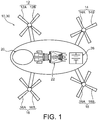
- the figure 1 illustrates a rotary wing aircraft 10, for example an octorotor aircraft, of the type comprising four pairs 12, 14, 16, 18 of counter-rotating propellers 12A, 12B, 14A, 14B, 16A, 16B, 18A, 18B.
- these propellers are respectively coupled to electric motors (not visible on the figure 1 ) which thus ensure the rotational drive of the propellers.
- These electric motors are themselves supplied with electric energy by an electric generator 20 driven by an internal combustion engine 22 such as a turbomachine.
- the connection between the electric generator 20 and the electric motors is operated in direct current, at a relatively high voltage, in order to improve the stability of the network and the power management.
- a rectifier converts the alternating current delivered by the electric generator 20 into direct current, while conversion means ensure the conversion of this direct current into alternating current intended for electric motors, as will appear more clearly in this article. following.
- the connection between the electric generator 20 and the direct current electric motors is in particular advantageous because the electric generator 20 operates at a constant speed and therefore makes it possible to have a stable direct voltage after conversion.
- an energy storage unit 26 is also provided for temporarily supplying the electric motors by supplementing or replacing the electric generator 20, in a manner known per se.
- the energy storage unit 26 is for example of the electrochemical type but can, as a variant, be of the electrostatic (capacitive) or mechanical type.
- the DC link mentioned above has in this case an additional advantage because such a link makes it possible to connect so simple the electric generator 20 and the energy storage unit 26, on the one hand, to the electric motors, on the other hand.
- the energy storage unit 26 can be connected to the rest of the system by means of a chopper, also called a DC-DC converter, making it possible in particular to ensure the correct recharging of the storage unit d. 'energy 26 and also to ensure redundancy of the electric chain in the event that the energy storage unit 26 should fail.
- a chopper also called a DC-DC converter
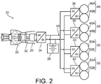
- the hybrid propulsion system 30 therefore comprises the internal combustion engine 22 and the electric generator 20.
- the latter typically comprises a rotor coupled to an output shaft 32, such as a shaft of a free or linked turbine, of the combustion engine. internal 22.
- An electrical output of the electrical generator 20 is connected to an input of the rectifier 34 to convert the AC alternating current supplied by the electrical generator 20 into DC direct current.
- An output of the rectifier 34 is connected in parallel, by means of an electrical network 44, to respective inputs of conversion means, namely a first inverter 36, a second inverter 38, a third inverter 40 and a fourth inverter 42, designed to reconvert the direct current DC into alternating current AC intended for the supply of the electric motors.
- the first inverter 36 has an output connected in parallel to a first group 46 of two first electric motors 46A, 46B, which the first inverter 36 thus supplies with AC alternating current.
- the other inverters 38, 40, 42 have respective outputs which are respectively connected in parallel to other groups 48, 50, 52 each comprising two other corresponding electric motors 48A, 48B, 50A, 50B, 52A, 52B .
- the hybrid propulsion system 30 thus comprises several groups each comprising two electric motors, and is configured so that the motors of the same group are supplied with electrical energy by the same corresponding inverter.
- the two electric motors 46A-52B of each group are respectively coupled to the two propellers of a corresponding pair 12-18 of counter-rotating propellers.
- the supply of electric motors by the same inverter makes it possible to reduce the mass of the hybrid propulsion system.
- the energy storage unit 26 is also connected in parallel to each of the inverters 36-42.
- the 46A-52B electric motors are all of the same type. However, to optimize the joint control and synchronization of the two motors of each group, the electric motors 46A-52B are distributed in the different groups 46-52 so as to present at least one intrinsic characteristic including the variance, calculated for the electric motors of any one of groups 46-52, or less than the variance of said intrinsic characteristic calculated for all of the electric motors 46A-52B. In other words, the electric motors are grouped according to the value of the aforementioned intrinsic characteristic in order to minimize the difference in value of this characteristic within each group.
- the intrinsic characteristic (s) considered are preferably electrical or electromagnetic characteristics such as stator resistors, synchronous inductors, and fluxes of rotor origin.
- the electric motors 46A-52B are polyphase asynchronous motors. These motors can be of different types such as induction motors or variable reluctance motors.
- the two electric motors in each group are of the multirotor single-stator type, which makes it possible to reduce the mass and the volume of the electric motors while helping to minimize the variance of the stator resistances of the electric motors within each group. .
- This makes it possible in particular to promote the equality of the respective electric currents within the two electric motors of the same group.
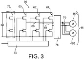
- the figure 3 illustrates an exemplary configuration of the first inverter 36 as well as the first two electric motors 46A, 46B.
- the other 38-42 inverters have a similar configuration.
- the first inverter 36 is a bridge inverter comprising three inverter arms 60, 62, 64 respectively delivering the three phases 66, 68, 70 of alternating current to each of the two first electric motors 46A, 46B.
- the first inverter 36 comprises a standby inverter arm 72 which is initially inoperative and which is intended to replace one of the three arms 60, 62, 64 in the event of failure of the latter.
- the first inverter 36 further comprises, in a conventional manner, a module 74 for controlling the inverter arms 60, 62, 64 and a module 76 for CEM filtering.
- the general principle of the invention consists in pooling the power supply to the electric motors of a hybrid propulsion system of a multirotor rotary-wing aircraft by means of inverters.
- the number of propellers may be greater than or less than 8. It may for example be equal to four in the case of an aircraft of the quadcopter type, sometimes referred to as a quadricopter.
- the propellers driven by the electric motors of the same group may not adopt a configuration of coaxial contra-rotating propellers.
- inverters can also vary, as can the type of these inverters.
- the number of electric motors supplied by the same inverter can be greater than two. It is however desirable for this number to remain relatively low in order to maintain sufficient redundancy of the propulsion units, such redundancy being desirable in order to guarantee the safety of the aircraft.
- the hybrid propulsion system therefore comprises at least one inverter and at least two electric motors supplied by this inverter.
Description
La présente invention concerne un système propulsif hybride destiné aux aéronefs à voilure tournante multirotor, ainsi qu'un procédé de fabrication d'un tel système propulsif hybride.The present invention relates to a hybrid propulsion system intended for multirotor rotary wing aircraft, as well as to a method of manufacturing such a hybrid propulsion system.
De l'état de la technique est connu un système propulsif hybride pour aéronef à voilure tournante multirotor comprenant :
- un moteur à combustion interne, et un générateur électrique accouplé au moteur à combustion interne de sorte qu'en fonctionnement, le moteur à combustion interne entraîne le générateur électrique,
- un redresseur relié au générateur électrique pour convertir un courant alternatif délivré par le générateur électrique en un courant continu, des moyens de conversion du courant continu en courant alternatif, et un réseau électrique reliant le redresseur aux moyens de conversion,
- des moteurs électriques reliés aux moyens de conversion de sorte qu'en fonctionnement, les moyens de conversion alimentent les premiers moteurs électriques en courant alternatif, et
- des hélices accouplées aux moteurs électriques de sorte qu'en fonctionnement, les moteurs électriques entraînent les hélices.
- an internal combustion engine, and an electric generator coupled to the internal combustion engine so that in operation, the internal combustion engine drives the electric generator,
- a rectifier connected to the electric generator to convert an alternating current delivered by the electric generator into a direct current, means for converting the direct current into alternating current, and an electrical network connecting the rectifier to the conversion means,
- electric motors connected to the conversion means so that, in operation, the conversion means supply the first electric motors with alternating current, and
- propellers coupled to electric motors so that in operation, the electric motors drive the propellers.
En particulier, les moyens de conversion comprennent des onduleurs respectivement reliés aux moteurs électriques de manière à alimenter ces derniers en courant alternatif.In particular, the conversion means comprise inverters respectively connected to the electric motors so as to supply the latter with alternating current.
Ces systèmes propulsifs présentent toutefois l'inconvénient d'être relativement lourds. Le document
L'invention a notamment pour but d'apporter une solution simple, économique et efficace à ce problème.The object of the invention is in particular to provide a simple, economical and effective solution to this problem.
Elle propose à cet effet un système propulsif hybride pour aéronef à voilure tournante, comprenant :
- un moteur à combustion interne et un générateur électrique accouplé au moteur à combustion interne de sorte qu'en fonctionnement, le moteur à combustion interne entraîne le générateur électrique,
- un redresseur relié au générateur électrique pour convertir un courant alternatif délivré par le générateur électrique en un courant continu, des moyens de conversion configurés pour convertir le courant continu en courant alternatif, et un réseau électrique reliant le redresseur aux moyens de conversion,
- au moins un premier groupe d'au moins deux premiers moteurs électriques reliés aux moyens de conversion de sorte qu'en fonctionnement, les moyens de conversion alimentent les premiers moteurs électriques en courant alternatif, et
- des hélices respectivement accouplées aux premiers moteurs électriques de sorte qu'en fonctionnement, les premiers moteurs électriques entraînent les hélices.
- an internal combustion engine and an electric generator coupled to the internal combustion engine so that in operation the internal combustion engine drives the electric generator,
- a rectifier connected to the electric generator to convert an alternating current delivered by the electric generator into a direct current, conversion means configured to convert the direct current into alternating current, and an electrical network connecting the rectifier to the conversion means,
- at least a first group of at least two first electric motors connected to the conversion means so that, in operation, the conversion means supply the first electric motors with alternating current, and
- propellers respectively coupled to the first electric motors so that in operation, the first electric motors drive the propellers.
Selon l'invention, les moyens de conversion comprennent un premier onduleur configuré pour alimenter en parallèle les premiers moteurs électriques.According to the invention, the conversion means comprise a first inverter configured to supply the first electric motors in parallel.
Le principe général de l'invention consiste ainsi à mutualiser l'alimentation de plusieurs moteurs électriques d'un système propulsif hybride d'aéronef à voilure tournante au moyen d'un même onduleur.The general principle of the invention thus consists in pooling the power supply of several electric motors of a hybrid propulsion system of a rotary wing aircraft by means of the same inverter.
L'invention permet ainsi une réduction de masse par rapport aux systèmes propulsifs hybrides de type connu, d'une part, par la réduction du nombre d'onduleurs, et également par la réduction du nombre et de la masse des filtres CEM.The invention thus allows a reduction in mass compared to hybrid propulsion systems of known type, on the one hand, by reducing the number of inverters, and also by reducing the number and mass of EMC filters.
De plus, l'alimentation de plusieurs moteurs électriques par un même onduleur permet d'optimiser la synchronisation de ces moteurs électriques. Ceci permet d'améliorer la portance du système propulsif hybride.In addition, the supply of several electric motors by the same inverter makes it possible to optimize the synchronization of these electric motors. This improves the lift of the hybrid propulsion system.
De préférence, les premiers moteurs électriques alimentés par le premier onduleur sont au nombre de deux.Preferably, the first electric motors supplied by the first inverter are two in number.
Dans certains modes de réalisation de l'invention, les hélices accouplées aux premiers moteurs électriques sont deux hélices contrarotatives coaxiales.In some embodiments of the invention, the propellers coupled to the first electric motors are two coaxial contra-rotating propellers.
Dans un mode de réalisation préféré de l'invention, le système propulsif hybride comprend au moins un autre groupe d'au moins deux autres moteurs électriques, et d'autres hélices respectivement accouplées à ces autres moteurs électriques, et les moyens de conversion comprennent, pour le ou chaque autre groupe d'autres moteurs électriques, un autre onduleur correspondant configuré pour alimenter en parallèle les autres moteurs électriques correspondants.In a preferred embodiment of the invention, the hybrid propulsion system comprises at least one other group of at least two other electric motors, and other propellers respectively coupled to these other electric motors, and the conversion means comprise, for the or each other group of other electric motors, another corresponding inverter configured to supply in parallel the other corresponding electric motors.
Dans ce cas, les premiers moteurs électriques et les autres moteurs électriques présentent avantageusement une caractéristique intrinsèque dont la variance, calculée pour les moteurs de l'un quelconque du premier groupe et de l'autre ou de chaque autre groupe, est inférieure à la variance de ladite caractéristique intrinsèque calculée pour l'ensemble des premiers moteurs électriques et des autres moteurs électriques.In this case, the first electric motors and the other electric motors advantageously exhibit an intrinsic characteristic whose variance, calculated for the motors of any one of the first group and of the other or of each other group, is less than the variance of said intrinsic characteristic calculated for all the first electric motors and the other electric motors.
La ou les caractéristiques intrinsèques considérées sont de préférence des caractéristiques électriques ou électromagnétiques telles que les résistances statoriques, les inductances synchrones, et les flux d'origine rotorique.The intrinsic characteristic (s) considered are preferably electrical or electromagnetic characteristics such as stator resistors, synchronous inductors, and fluxes of rotor origin.
De préférence, le système propulsif hybride comprend en outre une unité de stockage d'énergie reliée au réseau électrique en parallèle au générateur électrique.Preferably, the hybrid propulsion system further comprises an energy storage unit connected to the electrical network in parallel to the electrical generator.
L'invention concerne également un aéronef à voilure tournante multirotor, comprenant un système propulsif hybride du type décrit ci-dessus.The invention also relates to a multirotor rotary wing aircraft, comprising a hybrid propulsion system of the type described above.
L'invention concerne encore un procédé de fabrication d'un système propulsif hybride du type décrit ci-dessus, comprenant au moins les étapes consistant respectivement à :
- mettre à disposition une pluralité de moteurs électriques, des hélices, un moteur à combustion interne, un générateur électrique, un redresseur, un réseau électrique, et un premier onduleur;
- accoupler le générateur électrique au moteur à combustion interne ;
- relier le redresseur au générateur électrique ;
- relier le premier onduleur au redresseur au moyen du réseau électrique ;
- sélectionner, parmi la pluralité de moteurs électriques, un premier groupe d'au moins deux premiers moteurs électriques ;
- relier en parallèle les premiers moteurs électriques au premier onduleur ;
- accoupler une partie au moins des hélices aux premiers moteurs électriques.
- providing a plurality of electric motors, propellers, an internal combustion engine, an electric generator, a rectifier, a power grid, and a first inverter;
- coupling the electric generator to the internal combustion engine;
- connect the rectifier to the electric generator;
- connecting the first inverter to the rectifier by means of the electrical network;
- selecting, from among the plurality of electric motors, a first group of at least two first electric motors;
- connecting the first electric motors in parallel to the first inverter;
- couple at least part of the propellers to the first electric motors.
Dans le mode de réalisation préféré de l'invention, le procédé comprend en outre les étapes consistant respectivement à :
- sélectionner, parmi la pluralité de moteurs électriques, au moins un autre groupe d'au moins deux autres moteurs électriques ;
- mettre à disposition, pour le ou chaque autre groupe d'autres moteurs électriques, un autre onduleur correspondant ;
- relier en parallèle les autres moteurs électriques du ou de chaque autre groupe à l'autre onduleur correspondant.
- selecting, from the plurality of electric motors, at least one other group of at least two other electric motors;
- providing, for the or each other group of other electric motors, another corresponding inverter;
- connect the other electric motors of the or each other group in parallel to the other corresponding inverter.
De préférence, les premiers moteurs électriques et les autres moteurs électriques sont choisis de manière à présenter une caractéristique intrinsèque dont la variance, calculée pour les moteurs de l'un quelconque du premier groupe et de l'autre ou de chaque autre groupe, est inférieure à la variance de ladite caractéristique intrinsèque calculée pour l'ensemble des premiers moteurs électriques et des autres moteurs électriques.Preferably, the first electric motors and the other electric motors are chosen so as to have an intrinsic characteristic of which the variance, calculated for the motors of any one of the first group and of the other or of each other group, is less to the variance of said intrinsic characteristic calculated for all of the first electric motors and of the other electric motors.
L'invention sera mieux comprise, et d'autres détails, avantages et caractéristiques de celle-ci apparaîtront à la lecture de la description suivante faite à titre d'exemple non limitatif et en référence aux dessins annexés dans lesquels :
- la
figure 1 est une vue schématique de dessus d'un aéronef à voilure tournante multirotor selon un mode de réalisation préféré de l'invention ; - la
figure 2 est une vue schématique partielle d'un système propulsif hybride équipant l'aéronef de lafigure 1 ; - la
figure 3 est une vue schématique d'une partie du système propulsif hybride de lafigure 2 , illustrant en particulier un onduleur et deux moteurs électriques appartenant à ce système.
- the
figure 1 is a schematic top view of a multirotor rotary wing aircraft according to a preferred embodiment of the invention; - the
figure 2 is a partial schematic view of a hybrid propulsion system fitted to the aircraft of thefigure 1 ; - the
figure 3 is a schematic view of part of the hybrid propulsion system of thefigure 2 , illustrating in particular an inverter and two electric motors belonging to this system.
La
D'une manière générale, ces hélices sont respectivement accouplées à des moteurs électriques (non visibles sur la
Préférentiellement, une unité de stockage d'énergie 26 est également prévue pour alimenter temporairement les moteurs électriques en complétant ou en se substituant au générateur électrique 20, d'une manière connue en soi. L'unité de stockage d'énergie 26 est par exemple de type électrochimique mais peut, en variante, être de type électrostatique (capacitif) ou mécanique.Preferably, an
La liaison en courant continu mentionnée ci-dessus présente dans ce cas un avantage supplémentaire du fait qu'une telle liaison permet de relier de manière simple le générateur électrique 20 et l'unité de stockage d'énergie 26, d'une part, aux moteurs électriques, d'autre part.The DC link mentioned above has in this case an additional advantage because such a link makes it possible to connect so simple the
En variante, l'unité de stockage d'énergie 26 peut être reliée au reste du système par l'intermédiaire d'un hacheur, également dénommé convertisseur continu-continu, permettant notamment d'assurer la bonne recharge de l'unité de stockage d'énergie 26 et également d'assurer une redondance de la chaine électrique dans le cas où l'unité de stockage d'énergie 26 venait à être défaillante.As a variant, the
L'ensemble de ces éléments forme un système propulsif hybride 30, qui va maintenant être décrit plus en détail en référence à la
Le système propulsif hybride 30 comprend donc le moteur à combustion interne 22 et le générateur électrique 20. Ce dernier comporte typiquement un rotor accouplé à un arbre de sortie 32, tel qu'un arbre d'une turbine libre ou liée, du moteur à combustion interne 22.The
Une sortie électrique du générateur électrique 20 est reliée à une entrée du redresseur 34 pour convertir le courant alternatif AC fourni par le générateur électrique 20 en courant continu DC.An electrical output of the
Une sortie du redresseur 34 est reliée en parallèle, au moyen d'un réseau électrique 44, à des entrées respectives de moyens de conversion, à savoir un premier onduleur 36, un deuxième onduleur 38, un troisième onduleur 40 et un quatrième onduleur 42, prévus pour reconvertir le courant continu DC en courant alternatif AC destiné à l'alimentation des moteurs électriques.An output of the
Plus précisément, le premier onduleur 36 présente une sortie reliée en parallèle à un premier groupe 46 de deux premiers moteurs électriques 46A, 46B, que le premier onduleur 36 alimente ainsi en courant alternatif AC.More precisely, the
De manière analogue, les autres onduleurs 38, 40, 42 présentent des sorties respectives qui sont respectivement reliées en parallèle à d'autres groupes 48, 50, 52 comprenant chacun deux autres moteurs électriques correspondants 48A, 48B, 50A, 50B, 52A, 52B.Similarly, the
Le système propulsif hybride 30 comporte ainsi plusieurs groupes comprenant chacun deux moteurs électriques, et est configuré de sorte que les moteurs d'un même groupe soient alimentés en énergie électrique par un même onduleur correspondant.The
Les deux moteurs électriques 46A-52B de chaque groupe sont respectivement accouplés aux deux hélices d'une paire correspondante 12-18 d'hélices contrarotatives.The two
L'alimentation de moteurs électriques par un même onduleur permet de réduire la masse du système propulsif hybride.The supply of electric motors by the same inverter makes it possible to reduce the mass of the hybrid propulsion system.
De plus, une telle configuration permet une bonne synchronisation de ces moteurs, et donc des hélices entraînées par ces derniers. Ceci permet d'améliorer la portance du système propulsif hybride, particulièrement dans le cas d'un système à hélices contrarotatives tel que le système illustré sur les figures.In addition, such a configuration allows good synchronization of these motors, and therefore of the propellers driven by them. This makes it possible to improve the lift of the hybrid propulsion system, particularly in the case of a system with contra-rotating propellers such as the system illustrated in the figures.
Par ailleurs, l'unité de stockage d'énergie 26 est également reliée en parallèle à chacun des onduleurs 36-42.Furthermore, the
Les moteurs électriques 46A-52B sont tous de même type. Toutefois, pour optimiser la commande conjointe et la synchronisation des deux moteurs de chaque groupe, les moteurs électriques 46A-52B sont répartis dans les différents groupes 46-52 de manière à présenter au moins une caractéristique intrinsèque dont la variance, calculée pour les moteurs électriques de l'un quelconque des groupes 46-52, soit inférieure à la variance de ladite caractéristique intrinsèque calculée pour l'ensemble des moteurs électriques 46A-52B. Autrement dit, les moteurs électriques sont regroupés selon la valeur de la caractéristique intrinsèque précitée pour minimiser l'écart de valeur de cette caractéristique au sein de chaque groupe.The 46A-52B electric motors are all of the same type. However, to optimize the joint control and synchronization of the two motors of each group, the
La ou les caractéristiques intrinsèques considérées sont de préférence des caractéristiques électriques ou électromagnétiques telles que les résistances statoriques, les inductances synchrones, et les flux d'origine rotorique.The intrinsic characteristic (s) considered are preferably electrical or electromagnetic characteristics such as stator resistors, synchronous inductors, and fluxes of rotor origin.
Dans le mode de réalisation préféré de l'invention, les moteurs électriques 46A-52B sont des moteurs asynchrones polyphasés. Ces moteurs peuvent être de différents types tels que des moteurs à induction ou des moteurs à reluctance variable.In the preferred embodiment of the invention, the
À titre préférentiel, les deux moteurs électriques de chaque groupe sont du type mono-stator multirotor, ce qui permet de réduire la masse et le volume des moteurs électriques tout en aidant à minimiser la variance des résistances statoriques des moteurs électriques au sein de chaque groupe. Cela permet en particulier de favoriser l'égalité des courants électriques respectifs au sein des deux moteurs électriques d'un même groupe.Preferably, the two electric motors in each group are of the multirotor single-stator type, which makes it possible to reduce the mass and the volume of the electric motors while helping to minimize the variance of the stator resistances of the electric motors within each group. . This makes it possible in particular to promote the equality of the respective electric currents within the two electric motors of the same group.
La
Comme le montre la
Le système propulsif hybride 30 peut être fabriqué au moyen d'un procédé comprenant les étapes consistant à :
- mettre à disposition les moteurs électriques 46A-52B, les hélices 12A-18B, le moteur à
combustion interne 22, le générateur électrique 20,le redresseur 34, le réseau électrique 44, et les moyens de conversion constitués du premier onduleur 36, du deuxième onduleur 38, du troisième onduleur 40 et du quatrième onduleur 42 ; - accoupler le générateur électrique 20 au moteur à
combustion interne 22 ; - relier le redresseur 34 au générateur électrique 20 ;
- relier chacun des onduleurs 36-42
au redresseur 34 au moyen du réseau électrique 44 ; - répartir les moteurs électriques 46A-52B en groupes de deux moteurs, de sorte que la variance d'au moins une caractéristique intrinsèque des moteurs électriques calculée pour les moteurs de l'un quelconque des groupes 46-52, soit inférieure à la variance de ladite caractéristique intrinsèque calculée pour l'ensemble des moteurs électriques 46A-52B ;
- relier en parallèle les moteurs électriques de chaque groupe à un onduleur 36-42 correspondant ;
- accoupler les hélices respectivement aux moteurs électriques 46A-52B.
- provide the
electric motors 46A-52B, thepropellers 12A-18B, theinternal combustion engine 22, theelectric generator 20, therectifier 34, theelectric network 44, and the conversion means consisting of thefirst inverter 36, thesecond inverter 38, thethird inverter 40 and thefourth inverter 42; - coupling the
electric generator 20 to theinternal combustion engine 22; - connecting the
rectifier 34 to theelectric generator 20; - connecting each of the inverters 36-42 to the
rectifier 34 by means of theelectrical network 44; - divide the
electric motors 46A-52B into groups of two motors so that the variance of at least one intrinsic characteristic of the electric motors calculated for the motors of any of the groups 46-52 is less than the variance of said intrinsic characteristic calculated for all of theelectric motors 46A-52B; - connecting the electric motors of each group in parallel to a corresponding inverter 36-42;
- couple the propellers respectively to the
electric motors 46A-52B.
Comme expliqué ci-dessus, le principe général de l'invention consiste à mutualiser l'alimentation de moteurs électriques d'un système propulsif hybride d'aéronef à voilure tournante multirotor au moyen d'onduleurs.As explained above, the general principle of the invention consists in pooling the power supply to the electric motors of a hybrid propulsion system of a multirotor rotary-wing aircraft by means of inverters.
Ce principe général peut être appliqué à diverses configurations de systèmes propulsifs hybrides, sans sortir du cadre de la présente invention.This general principle can be applied to various configurations of hybrid propulsion systems, without departing from the scope of the present invention.
Ainsi, le nombre d'hélices peut être supérieur ou inférieur à 8. Il peut par exemple être égal à quatre dans le cas d'un aéronef de type quadrirotor, parfois dénommé quadricoptère. De plus, les hélices entraînées par les moteurs électriques d'un même groupe peuvent ne pas adopter une configuration d'hélices contrarotatives coaxiales.Thus, the number of propellers may be greater than or less than 8. It may for example be equal to four in the case of an aircraft of the quadcopter type, sometimes referred to as a quadricopter. In addition, the propellers driven by the electric motors of the same group may not adopt a configuration of coaxial contra-rotating propellers.
Le nombre d'onduleurs peut également varier, de même que le type de ces onduleurs.The number of inverters can also vary, as can the type of these inverters.
De plus, le nombre de moteurs électriques alimentés par un même onduleur peut être supérieur à deux. Il est cependant souhaitable que ce nombre reste relativement bas pour conserver une redondance suffisante des organes propulsifs, une telle redondance étant souhaitable pour garantir la sécurité de l'aéronef.In addition, the number of electric motors supplied by the same inverter can be greater than two. It is however desirable for this number to remain relatively low in order to maintain sufficient redundancy of the propulsion units, such redundancy being desirable in order to guarantee the safety of the aircraft.
Sous son aspect le plus général, le système propulsif hybride selon l'invention comporte donc au moins un onduleur et au moins deux moteurs électriques alimentés par cet onduleur.In its most general aspect, the hybrid propulsion system according to the invention therefore comprises at least one inverter and at least two electric motors supplied by this inverter.
Claims (10)
- A hybrid propulsion system (30) for a multi-rotor rotary wing aircraft (10), comprising:- an internal combustion engine (22) and an electric generator (20) coupled to the internal combustion engine such that in use, the internal combustion engine drives the electric generator,- a rectifier (34) connected to the electric generator to convert an alternating current delivered by the electric generator into a direct current, conversion means configured to convert the direct current into alternating current, and an electric network (44) connecting the rectifier to the conversion means,- at least one first group (46) of at least two first electric motors (46A, 46B) connected to the conversion means such that in use, the conversion means supply the first electric motors with alternating current,- propellers (12A, 12B) respectively coupled to the first electric motors such that in use, the first electric motors drive the propellers, characterised in that the conversion means comprise a first inverter (36) configured to supply the first electric motors in parallel.
- The hybrid propulsion system according to claim 1, wherein the first electric motors (46A, 46B) supplied by the first inverter (36) are two in number.
- The hybrid propulsion system according to claim 2, wherein the propellers (12A, 12B) coupled to the first electric motors (46A, 46B) are two coaxial contra-rotating propellers.
- The hybrid propulsion system according to any of claims 1 to 3, comprising at least one other group (48, 50, 52) of at least two other electric motors (48A, 48B, 50A, 50B, 52A, 52B), and other propellers (14A, 14B, 16A, 16B, 18A, 18B) respectively coupled to these other electric motors, and wherein the conversion means comprise, for the or each other group of other electric motors, another corresponding inverter (38, 40, 42) configured to supply the other corresponding electric motors in parallel.
- The hybrid propulsion system according to claim 4, wherein the first electric motors (46A, 46B) and the other electric motors (48A, 48B, 50A, 50B, 52A, 52B) have an intrinsic characteristic the variance of which, calculated for the motors of any of the first group (46) and the other or each other group (48, 50, 52), is lower than the variance of said intrinsic characteristic calculated for all the first electric motors and the other electric motors.
- The hybrid propulsion system according to any of claims 1 to 5, further comprising an energy storage unit (26) connected to the electric network (44) in parallel with the electric generator (20).
- A multi-rotor rotary wing aircraft (10), comprising a hybrid propulsion system (30) according to any of claims 1 to 6.
- A method for manufacturing a hybrid propulsion system (30) according to any of claims 1 to 6, comprising at least the respective steps of:- providing a plurality of electric motors, propellers, an internal combustion engine (22), an electric generator (20), a rectifier (34), an electric network (44), and a first inverter (36);- coupling the electric generator (20) to the internal combustion engine (22);- connecting the rectifier (34) to the electric generator (20);- connecting the first inverter (36) to the rectifier (34) by means of the electric network (44);- selecting, among the plurality of electric motors, a first group (46) of at least two first electric motors (46A, 46B);- connecting the first electric motors (46A, 46B) in parallel with the first inverter (36);- coupling at least part of the propellers (12A, 12B) to the first electric motors (46A, 46B).
- The method according to claim 8 for manufacturing a hybrid propulsion system (30) according to claim 5, further comprising the respective steps of:- selecting, among the plurality of electric motors, at least one other group (48, 50, 52) of at least two other electric motors (48A, 48B, 50A, 50B, 52A, 52B);- providing, for the or each other group of other electric motors, another corresponding inverter (38, 40, 42);- connecting the other electric motors of the or each other group in parallel with the corresponding other inverter.
- The method according to claim 9, wherein the first electric motors (46A, 46B) and the other electric motors (48A, 48B, 50A, 50B, 52A, 52B) are chosen so as to have an intrinsic characteristic the variance of which, calculated for the motors of any of the first group (46) and the other or each other group (48, 50, 52), is lower than the variance of said intrinsic characteristic calculated for all the first electric motors and the other electric motors.
Applications Claiming Priority (2)
| Application Number | Priority Date | Filing Date | Title |
|---|---|---|---|
| FR1659366A FR3056555B1 (en) | 2016-09-29 | 2016-09-29 | HYBRID PROPULSIVE SYSTEM FOR MULTIROTOR ROTARY FLYWELL AIRCRAFT COMPRISING IMPROVED DC / AC CONVERSION MEANS |
| PCT/FR2017/052595 WO2018060591A1 (en) | 2016-09-29 | 2017-09-27 | Hybrid propulsion system for multi-rotor rotary-wing aircraft, comprising improved dc/ac conversion means |
Publications (2)
| Publication Number | Publication Date |
|---|---|
| EP3519294A1 EP3519294A1 (en) | 2019-08-07 |
| EP3519294B1 true EP3519294B1 (en) | 2020-11-11 |
Family
ID=57396704
Family Applications (1)
| Application Number | Title | Priority Date | Filing Date |
|---|---|---|---|
| EP17783943.8A Active EP3519294B1 (en) | 2016-09-29 | 2017-09-27 | Hybrid propulsion system for multi-rotor rotary-wing aircraft, comprising improved dc/ac conversion means |
Country Status (9)
| Country | Link |
|---|---|
| US (1) | US11608184B2 (en) |
| EP (1) | EP3519294B1 (en) |
| JP (1) | JP2019534821A (en) |
| KR (1) | KR20190055189A (en) |
| CN (1) | CN109789923B (en) |
| CA (1) | CA3038299A1 (en) |
| FR (1) | FR3056555B1 (en) |
| RU (1) | RU2745465C2 (en) |
| WO (1) | WO2018060591A1 (en) |
Cited By (1)
| Publication number | Priority date | Publication date | Assignee | Title |
|---|---|---|---|---|
| WO2023131755A1 (en) | 2022-01-07 | 2023-07-13 | Safran Helicopter Engines | Dc-to-dc converter for an electrical aircraft propulsion system |
Families Citing this family (28)
| Publication number | Priority date | Publication date | Assignee | Title |
|---|---|---|---|---|
| FR3056555B1 (en) * | 2016-09-29 | 2018-12-07 | Safran Helicopter Engines | HYBRID PROPULSIVE SYSTEM FOR MULTIROTOR ROTARY FLYWELL AIRCRAFT COMPRISING IMPROVED DC / AC CONVERSION MEANS |
| FR3057120B1 (en) * | 2016-10-03 | 2023-03-17 | Safran Helicopter Engines | ELECTRIC MACHINE FOR AIRCRAFT TURBOPROPELLER |
| GB201802611D0 (en) * | 2018-02-17 | 2018-04-04 | Panelplane Ltd | Teleporter |
| US10906637B2 (en) * | 2018-05-17 | 2021-02-02 | Textron Innovations Inc. | Assisted landing systems for rotorcraft |
| FR3087756B1 (en) | 2018-10-29 | 2022-04-01 | Safran Helicopter Engines | HYBRID POWER SUPPLY SYSTEM FOR AIRCRAFT |
| US11159024B2 (en) | 2018-11-08 | 2021-10-26 | Rolls-Royce North American Technologies, Inc. | Electrical architecture for hybrid propulsion |
| US10759540B2 (en) | 2018-11-08 | 2020-09-01 | Rolls-Royce North American Technologies, Inc. | Hybrid propulsion systems |
| US11225881B2 (en) | 2018-11-08 | 2022-01-18 | Rolls-Royce North American Technologies, Inc. | Hybrid propulsion systems |
| US11370554B2 (en) * | 2018-11-08 | 2022-06-28 | Rolls-Royce North American Technologies, Inc. | Hybrid propulsion systems |
| FR3092317B1 (en) | 2019-02-01 | 2021-01-08 | Safran Electrical & Power | AIRCRAFT PROPULSION SYSTEM |
| FR3093080B1 (en) * | 2019-02-26 | 2021-03-05 | Safran Helicopter Engines | HYBRID-ELECTRIC PROPULSIVE ARCHITECTURE AND ELECTRICAL ENERGY DISSIPATION PROCESS IN SUCH ARCHITECTURE |
| FR3094697B1 (en) * | 2019-04-02 | 2021-03-19 | Safran Helicopter Engines | HYBRID PROPULSIVE INSTALLATION FOR AN AIRCRAFT |
| FR3095191B1 (en) | 2019-04-16 | 2021-04-23 | Safran Helicopter Engines | HYBRID PROPULSION SYSTEM AND PROCESS FOR CONTROL OF SUCH A SYSTEM |
| FR3095415B1 (en) | 2019-04-26 | 2022-07-22 | Safran Helicopter Engines | PROPULSION SYSTEM FOR MULTI-ROTOR AIRCRAFT WITH NETWORK OF RECONFIGURABLE ELECTRICAL ENERGY STORAGE UNITS |
| FR3095806B1 (en) | 2019-05-06 | 2021-08-20 | Safran Helicopter Engines | Hybrid propulsion system for vertical take-off and landing aircraft |
| FR3098497B1 (en) * | 2019-07-09 | 2021-07-09 | Safran Helicopter Engines | Hybrid propulsion chain for aircraft comprising an auxiliary mechanical drive system |
| FR3099134B1 (en) | 2019-07-25 | 2021-10-15 | Airbus Helicopters | Power supply method for an electrical network and electrical architecture |
| RU2727287C1 (en) * | 2019-10-23 | 2020-07-21 | Российская Федерация, от имени которой выступает Министерство промышленности и торговли Российской Федерации (Минпромторг России) | Hybrid power plant |
| EP3823070A1 (en) | 2019-11-12 | 2021-05-19 | AIRBUS HELICOPTERS DEUTSCHLAND GmbH | A hybrid energy storage system |
| ES2954854T3 (en) * | 2020-01-08 | 2023-11-27 | Swissdrones Operating Ag | air vehicle |
| US20210237615A1 (en) * | 2020-02-03 | 2021-08-05 | Wisk Aero Llc | Redundant power distribution circuits for electric vehicles |
| WO2021210062A1 (en) * | 2020-04-14 | 2021-10-21 | 川崎重工業株式会社 | Multicopter and method for driving same |
| WO2021210063A1 (en) * | 2020-04-14 | 2021-10-21 | 川崎重工業株式会社 | Multicopter |
| WO2021210065A1 (en) * | 2020-04-14 | 2021-10-21 | 川崎重工業株式会社 | Multicopter |
| WO2021220491A1 (en) * | 2020-04-30 | 2021-11-04 | ヤマハ発動機株式会社 | Flight vehicle engine generator unit, and flight vehicle |
| WO2021220490A1 (en) * | 2020-04-30 | 2021-11-04 | ヤマハ発動機株式会社 | Engine generator unit for flying object, and flying object |
| JP7133745B2 (en) * | 2020-04-30 | 2022-09-08 | ヤマハ発動機株式会社 | Aircraft engine generator unit and aircraft |
| US11670942B2 (en) | 2021-09-23 | 2023-06-06 | General Electric Company | Electrically driven distributed propulsion system |
Family Cites Families (53)
| Publication number | Priority date | Publication date | Assignee | Title |
|---|---|---|---|---|
| US1754192A (en) * | 1925-09-28 | 1930-04-08 | John Dumans Van Vliet | Multipower-plant transmission for aircraft and the like |
| US2462201A (en) * | 1943-02-02 | 1949-02-22 | Westinghouse Electric Corp | Electrical airplane propulsion |
| US2604949A (en) * | 1945-10-04 | 1952-07-29 | Firestone Tire & Rubber Co | Helicopter control |
| US2499314A (en) * | 1947-09-12 | 1950-02-28 | United Aircraft Corp | Two-bladed tail rotor on common hinge |
| US2698147A (en) * | 1950-09-01 | 1954-12-28 | Paul E Hovgard | Aircraft with fixed wings and lifting rotor |
| US3332404A (en) * | 1965-02-15 | 1967-07-25 | Charles L Lovercheck | Dual engine |
| US3332643A (en) * | 1965-10-05 | 1967-07-25 | Piasecki Aircraft Corp | Control system for aircraft |
| US4554989A (en) * | 1983-01-20 | 1985-11-26 | Peter Gruich | Multimotor modular electric drive powertrain system for turbine powered vehicles |
| AUPP105297A0 (en) * | 1997-12-22 | 1998-01-15 | Kusic, Tom | Tandem rotor vertical take-off variable body aircraft |
| US6464459B2 (en) * | 1999-05-21 | 2002-10-15 | Avionic Instruments, Inc. | Lifting platform with energy recovery |
| US6382556B1 (en) * | 1999-12-20 | 2002-05-07 | Roger N. C. Pham | VTOL airplane with only one tiltable prop-rotor |
| AUPR345501A0 (en) * | 2001-03-01 | 2001-03-29 | Kusic, Tom | Tandem tilt rotor aircraft |
| US20030192303A1 (en) * | 2002-04-15 | 2003-10-16 | Paul Marius A. | Integrated bypass turbojet engines for aircraft and other vehicles |
| AUPS330502A0 (en) * | 2002-06-28 | 2002-07-25 | Kusic, Tom | Tandem powered power tilting aircraft - june 2002 |
| DE10301978A1 (en) * | 2003-01-20 | 2004-08-05 | Eurocopter Deutschland Gmbh | Device and method for transmitting and providing the energy of capacitive actuators |
| DE102004063205B3 (en) * | 2004-12-23 | 2006-05-04 | Julian Kuntz | Aircraft for transporting persons, has rotors/propellers with sheathings, which enable independent drive movement of aircraft on land according to function of wheel rims based on direct power transmission from aircraft to land |
| WO2006113877A2 (en) * | 2005-04-20 | 2006-10-26 | Lugg Richard H | Hybrid jet/electric vtol aircraft |
| US20070181742A1 (en) * | 2006-01-19 | 2007-08-09 | Silverlit Toys Manufactory, Ltd. | Flying object with tandem rotors |
| US20080184906A1 (en) * | 2007-02-07 | 2008-08-07 | Kejha Joseph B | Long range hybrid electric airplane |
| JP4946854B2 (en) * | 2007-06-25 | 2012-06-06 | マツダ株式会社 | Control device and control method for hybrid vehicle |
| US8058830B2 (en) * | 2007-07-30 | 2011-11-15 | GM Global Technology Operations LLC | Charging energy sources with a rectifier using double-ended inverter system |
| US20090230235A1 (en) * | 2008-03-11 | 2009-09-17 | Mcnulty Norbert Edward | Tambourine helicopter |
| US8646720B2 (en) * | 2010-05-10 | 2014-02-11 | Donald Orval Shaw | Modular flight vehicle with wings |
| US20100044499A1 (en) * | 2008-08-22 | 2010-02-25 | Draganfly Innovations Inc. | Six rotor helicopter |
| US20110001020A1 (en) * | 2009-07-02 | 2011-01-06 | Pavol Forgac | Quad tilt rotor aerial vehicle with stoppable rotors |
| DE102010021025B4 (en) * | 2010-05-19 | 2014-05-08 | Eads Deutschland Gmbh | Hybrid helicopter |
| DE102010021026A1 (en) * | 2010-05-19 | 2011-11-24 | Eads Deutschland Gmbh | Hybrid propulsion and power system for aircraft |
| FR2962407B1 (en) * | 2010-07-06 | 2013-05-17 | Hispano Suiza Sa | SUPPLYING ELECTRICAL EQUIPMENT OF AN AIRCRAFT |
| FR2962713A1 (en) * | 2010-07-13 | 2012-01-20 | Eurocopter France | METHOD AND AIRCRAFT PROVIDED WITH A BACK-UP ROTOR |
| FR2979614B1 (en) * | 2011-09-04 | 2013-09-20 | Eric Chantriaux | ELECTROMAGNETIC POWER TRANSMISSION FOR AN AIRCRAFT WITH A ROTARY OR FIXED SAIL. |
| FR2978728B1 (en) * | 2011-08-03 | 2014-07-04 | Eads Europ Aeronautic Defence | AIRCRAFT PROPULSION ARCHITECTURE INTEGRATING AN ENERGY RECOVERY SYSTEM |
| FR2979615B1 (en) * | 2011-09-04 | 2013-09-20 | Eric Chantriaux | AIRCRAFT EQUIPPED WITH AN ELECTROMOTEUR GROUP DISTRIBUTED TO FREE WHEELS. |
| FR2990573B1 (en) * | 2012-05-11 | 2015-11-20 | Hispano Suiza Sa | SYSTEM FOR CONTROLLING AND POWERING TURBOMACHINES OF A HELICOPTER |
| FR2992733B1 (en) * | 2012-06-28 | 2014-08-08 | Labinal | DEVICE AND METHOD FOR MONITORING AN ELECTRICAL NETWORK |
| US8844860B2 (en) * | 2012-07-06 | 2014-09-30 | Lapcad Engineering, Inc. | Foldable rise and stare vehicle |
| US8794566B2 (en) * | 2012-08-02 | 2014-08-05 | Neurosciences Research Foundation, Inc. | Vehicle capable of stabilizing a payload when in motion |
| US9586690B2 (en) * | 2013-03-14 | 2017-03-07 | Rolls-Royce Corporation | Hybrid turbo electric aero-propulsion system control |
| US9193451B2 (en) * | 2013-04-22 | 2015-11-24 | Ival O. Salyer | Aircraft using turbo-electric hybrid propulsion system for multi-mode operation |
| JP2015137092A (en) * | 2014-01-20 | 2015-07-30 | 憲太 安田 | Parallel hybrid multi-rotor aircraft |
| RU2550876C1 (en) * | 2014-01-21 | 2015-05-20 | Общество с ограниченной ответственностью "Научно-производственное предприятие "Резонанс" | Electric equipment system for track-laying vehicle |
| EP3543120B1 (en) * | 2014-03-13 | 2024-01-24 | Endurant Systems LLC | Battery augmentation for uav internal combustion engines |
| US20160059958A1 (en) * | 2014-08-19 | 2016-03-03 | Tau Emerald Rotors Inc. | Controlling Rotary Wing Aircraft |
| CN115946858A (en) * | 2014-08-29 | 2023-04-11 | 峰鸟航空科技公司 | System and method for implementing regional air transport network using hybrid electric aircraft |
| JP6730842B2 (en) * | 2015-05-05 | 2020-07-29 | ロールス−ロイス コーポレイション | Electric direct drive for aircraft propulsion and lift |
| US10284129B2 (en) * | 2015-09-16 | 2019-05-07 | Eaton Intelligent Power Limited | Three-phase variable reference pulse width modulation |
| AU2016366741B2 (en) * | 2015-12-09 | 2021-10-14 | Ideaforge Technology Pvt. Ltd. | Multi-rotor aerial vehicle with single arm failure redundancy |
| US10926874B2 (en) * | 2016-01-15 | 2021-02-23 | Aurora Flight Sciences Corporation | Hybrid propulsion vertical take-off and landing aircraft |
| CN205554582U (en) * | 2016-03-03 | 2016-09-07 | 上海奥科赛飞机有限公司 | Land, water and air three way rotor airborne vehicle |
| CN105711826A (en) * | 2016-03-31 | 2016-06-29 | 陈萌 | Tandem type oil-electric hybrid unmanned aerial vehicle |
| FR3056555B1 (en) * | 2016-09-29 | 2018-12-07 | Safran Helicopter Engines | HYBRID PROPULSIVE SYSTEM FOR MULTIROTOR ROTARY FLYWELL AIRCRAFT COMPRISING IMPROVED DC / AC CONVERSION MEANS |
| FR3057120B1 (en) * | 2016-10-03 | 2023-03-17 | Safran Helicopter Engines | ELECTRIC MACHINE FOR AIRCRAFT TURBOPROPELLER |
| WO2018076047A1 (en) * | 2016-10-24 | 2018-05-03 | Hybridskys Technology Pty Ltd | Hybrid aircraft |
| US9837952B1 (en) * | 2016-12-16 | 2017-12-05 | Hamilton Sundstrand Corporation | Reducing resonant effects of reactive loads in electric motor systems |
-
2016
- 2016-09-29 FR FR1659366A patent/FR3056555B1/en active Active
-
2017
- 2017-09-27 CN CN201780059691.4A patent/CN109789923B/en active Active
- 2017-09-27 JP JP2019517071A patent/JP2019534821A/en active Pending
- 2017-09-27 KR KR1020197011625A patent/KR20190055189A/en not_active Application Discontinuation
- 2017-09-27 US US16/336,537 patent/US11608184B2/en active Active
- 2017-09-27 CA CA3038299A patent/CA3038299A1/en not_active Abandoned
- 2017-09-27 RU RU2019112618A patent/RU2745465C2/en active
- 2017-09-27 WO PCT/FR2017/052595 patent/WO2018060591A1/en unknown
- 2017-09-27 EP EP17783943.8A patent/EP3519294B1/en active Active
Cited By (2)
| Publication number | Priority date | Publication date | Assignee | Title |
|---|---|---|---|---|
| WO2023131755A1 (en) | 2022-01-07 | 2023-07-13 | Safran Helicopter Engines | Dc-to-dc converter for an electrical aircraft propulsion system |
| FR3131812A1 (en) | 2022-01-07 | 2023-07-14 | Safran Helicopter Engines | DC/DC CONVERTER FOR AN AIRCRAFT PROPULSION ELECTRICAL NETWORK |
Also Published As
| Publication number | Publication date |
|---|---|
| RU2745465C2 (en) | 2021-03-25 |
| JP2019534821A (en) | 2019-12-05 |
| RU2019112618A (en) | 2020-10-29 |
| US11608184B2 (en) | 2023-03-21 |
| US20200115062A1 (en) | 2020-04-16 |
| CA3038299A1 (en) | 2018-04-05 |
| CN109789923B (en) | 2023-01-17 |
| CN109789923A (en) | 2019-05-21 |
| FR3056555A1 (en) | 2018-03-30 |
| WO2018060591A1 (en) | 2018-04-05 |
| KR20190055189A (en) | 2019-05-22 |
| RU2019112618A3 (en) | 2021-01-26 |
| FR3056555B1 (en) | 2018-12-07 |
| EP3519294A1 (en) | 2019-08-07 |
Similar Documents
| Publication | Publication Date | Title |
|---|---|---|
| EP3519294B1 (en) | Hybrid propulsion system for multi-rotor rotary-wing aircraft, comprising improved dc/ac conversion means | |
| EP2260560B1 (en) | Method for managing electrical network | |
| EP2494184B1 (en) | Starter-generator of a turbomachine and control method therefor | |
| CA2667270C (en) | System for generating, converting, distributing and electrically starting on board an aircraft | |
| CA2893436C (en) | Method for managing the electric power network of an aircraft | |
| EP2830938B1 (en) | Aircraft ground power supply system | |
| FR2897895A1 (en) | Transmission unit and starter-generator assembly for gas turbine, has synchronous generator and exciter placed on sides of pinion and with respective rotors mounted on shaft, and transmission unit and starter-generator placed in common case | |
| WO2006087379A1 (en) | Electric supply for an aircraft gas turbine engine equipment | |
| WO2013017789A2 (en) | Device for supplying an aircraft on the ground with electricity | |
| EP3931039A1 (en) | Hybrid/electric propulsion architecture and method for dissipating electrical energy in such an architecture | |
| EP4244467A1 (en) | Hybrid propulsion turbomachine and aircraft comprising such a turbomachine | |
| WO2015114252A1 (en) | Electrical conversion and distribution system for an aircraft | |
| EP3122627B1 (en) | Transmission assembly for an aircraft and a helicopter | |
| WO2019012010A1 (en) | Method for controlling a multiphase rotary electric machine and rotary electric machine using same | |
| EP3972901B1 (en) | Hybrid aircraft drive train with auxiliar mechanical drive | |
| EP3494047B1 (en) | Power supply network architecture | |
| FR3135843A1 (en) | Synchronous electric machine for aircraft, propulsion device, turbine engine and associated method | |
| WO2023281210A1 (en) | Electrical generation architecture for hybrid turbine engine | |
| WO2022112713A1 (en) | Pump actuating device, and associated pumping system, aircraft and fuel supply method |
Legal Events
| Date | Code | Title | Description |
|---|---|---|---|
| STAA | Information on the status of an ep patent application or granted ep patent |
Free format text: STATUS: UNKNOWN |
|
| STAA | Information on the status of an ep patent application or granted ep patent |
Free format text: STATUS: THE INTERNATIONAL PUBLICATION HAS BEEN MADE |
|
| PUAI | Public reference made under article 153(3) epc to a published international application that has entered the european phase |
Free format text: ORIGINAL CODE: 0009012 |
|
| STAA | Information on the status of an ep patent application or granted ep patent |
Free format text: STATUS: REQUEST FOR EXAMINATION WAS MADE |
|
| 17P | Request for examination filed |
Effective date: 20190401 |
|
| AK | Designated contracting states |
Kind code of ref document: A1 Designated state(s): AL AT BE BG CH CY CZ DE DK EE ES FI FR GB GR HR HU IE IS IT LI LT LU LV MC MK MT NL NO PL PT RO RS SE SI SK SM TR |
|
| AX | Request for extension of the european patent |
Extension state: BA ME |
|
| DAV | Request for validation of the european patent (deleted) | ||
| DAX | Request for extension of the european patent (deleted) | ||
| GRAP | Despatch of communication of intention to grant a patent |
Free format text: ORIGINAL CODE: EPIDOSNIGR1 |
|
| STAA | Information on the status of an ep patent application or granted ep patent |
Free format text: STATUS: GRANT OF PATENT IS INTENDED |
|
| RIC1 | Information provided on ipc code assigned before grant |
Ipc: B64C 27/08 20060101AFI20200512BHEP Ipc: B64D 27/02 20060101ALI20200512BHEP |
|
| INTG | Intention to grant announced |
Effective date: 20200602 |
|
| GRAS | Grant fee paid |
Free format text: ORIGINAL CODE: EPIDOSNIGR3 |
|
| GRAA | (expected) grant |
Free format text: ORIGINAL CODE: 0009210 |
|
| STAA | Information on the status of an ep patent application or granted ep patent |
Free format text: STATUS: THE PATENT HAS BEEN GRANTED |
|
| AK | Designated contracting states |
Kind code of ref document: B1 Designated state(s): AL AT BE BG CH CY CZ DE DK EE ES FI FR GB GR HR HU IE IS IT LI LT LU LV MC MK MT NL NO PL PT RO RS SE SI SK SM TR |
|
| REG | Reference to a national code |
Ref country code: GB Ref legal event code: FG4D Free format text: NOT ENGLISH |
|
| REG | Reference to a national code |
Ref country code: CH Ref legal event code: EP |
|
| REG | Reference to a national code |
Ref country code: AT Ref legal event code: REF Ref document number: 1333222 Country of ref document: AT Kind code of ref document: T Effective date: 20201115 |
|
| REG | Reference to a national code |
Ref country code: DE Ref legal event code: R096 Ref document number: 602017027466 Country of ref document: DE |
|
| REG | Reference to a national code |
Ref country code: IE Ref legal event code: FG4D Free format text: LANGUAGE OF EP DOCUMENT: FRENCH |
|
| REG | Reference to a national code |
Ref country code: NL Ref legal event code: MP Effective date: 20201111 |
|
| REG | Reference to a national code |
Ref country code: AT Ref legal event code: MK05 Ref document number: 1333222 Country of ref document: AT Kind code of ref document: T Effective date: 20201111 |
|
| PG25 | Lapsed in a contracting state [announced via postgrant information from national office to epo] |
Ref country code: NO Free format text: LAPSE BECAUSE OF FAILURE TO SUBMIT A TRANSLATION OF THE DESCRIPTION OR TO PAY THE FEE WITHIN THE PRESCRIBED TIME-LIMIT Effective date: 20210211 Ref country code: GR Free format text: LAPSE BECAUSE OF FAILURE TO SUBMIT A TRANSLATION OF THE DESCRIPTION OR TO PAY THE FEE WITHIN THE PRESCRIBED TIME-LIMIT Effective date: 20210212 Ref country code: FI Free format text: LAPSE BECAUSE OF FAILURE TO SUBMIT A TRANSLATION OF THE DESCRIPTION OR TO PAY THE FEE WITHIN THE PRESCRIBED TIME-LIMIT Effective date: 20201111 Ref country code: RS Free format text: LAPSE BECAUSE OF FAILURE TO SUBMIT A TRANSLATION OF THE DESCRIPTION OR TO PAY THE FEE WITHIN THE PRESCRIBED TIME-LIMIT Effective date: 20201111 Ref country code: PT Free format text: LAPSE BECAUSE OF FAILURE TO SUBMIT A TRANSLATION OF THE DESCRIPTION OR TO PAY THE FEE WITHIN THE PRESCRIBED TIME-LIMIT Effective date: 20210311 |
|
| PG25 | Lapsed in a contracting state [announced via postgrant information from national office to epo] |
Ref country code: AT Free format text: LAPSE BECAUSE OF FAILURE TO SUBMIT A TRANSLATION OF THE DESCRIPTION OR TO PAY THE FEE WITHIN THE PRESCRIBED TIME-LIMIT Effective date: 20201111 Ref country code: BG Free format text: LAPSE BECAUSE OF FAILURE TO SUBMIT A TRANSLATION OF THE DESCRIPTION OR TO PAY THE FEE WITHIN THE PRESCRIBED TIME-LIMIT Effective date: 20210211 Ref country code: SE Free format text: LAPSE BECAUSE OF FAILURE TO SUBMIT A TRANSLATION OF THE DESCRIPTION OR TO PAY THE FEE WITHIN THE PRESCRIBED TIME-LIMIT Effective date: 20201111 Ref country code: IS Free format text: LAPSE BECAUSE OF FAILURE TO SUBMIT A TRANSLATION OF THE DESCRIPTION OR TO PAY THE FEE WITHIN THE PRESCRIBED TIME-LIMIT Effective date: 20210311 Ref country code: LV Free format text: LAPSE BECAUSE OF FAILURE TO SUBMIT A TRANSLATION OF THE DESCRIPTION OR TO PAY THE FEE WITHIN THE PRESCRIBED TIME-LIMIT Effective date: 20201111 |
|
| REG | Reference to a national code |
Ref country code: LT Ref legal event code: MG9D |
|
| PG25 | Lapsed in a contracting state [announced via postgrant information from national office to epo] |
Ref country code: HR Free format text: LAPSE BECAUSE OF FAILURE TO SUBMIT A TRANSLATION OF THE DESCRIPTION OR TO PAY THE FEE WITHIN THE PRESCRIBED TIME-LIMIT Effective date: 20201111 |
|
| PG25 | Lapsed in a contracting state [announced via postgrant information from national office to epo] |
Ref country code: RO Free format text: LAPSE BECAUSE OF FAILURE TO SUBMIT A TRANSLATION OF THE DESCRIPTION OR TO PAY THE FEE WITHIN THE PRESCRIBED TIME-LIMIT Effective date: 20201111 Ref country code: SK Free format text: LAPSE BECAUSE OF FAILURE TO SUBMIT A TRANSLATION OF THE DESCRIPTION OR TO PAY THE FEE WITHIN THE PRESCRIBED TIME-LIMIT Effective date: 20201111 Ref country code: SM Free format text: LAPSE BECAUSE OF FAILURE TO SUBMIT A TRANSLATION OF THE DESCRIPTION OR TO PAY THE FEE WITHIN THE PRESCRIBED TIME-LIMIT Effective date: 20201111 Ref country code: EE Free format text: LAPSE BECAUSE OF FAILURE TO SUBMIT A TRANSLATION OF THE DESCRIPTION OR TO PAY THE FEE WITHIN THE PRESCRIBED TIME-LIMIT Effective date: 20201111 Ref country code: LT Free format text: LAPSE BECAUSE OF FAILURE TO SUBMIT A TRANSLATION OF THE DESCRIPTION OR TO PAY THE FEE WITHIN THE PRESCRIBED TIME-LIMIT Effective date: 20201111 |
|
| REG | Reference to a national code |
Ref country code: DE Ref legal event code: R097 Ref document number: 602017027466 Country of ref document: DE |
|
| PG25 | Lapsed in a contracting state [announced via postgrant information from national office to epo] |
Ref country code: DK Free format text: LAPSE BECAUSE OF FAILURE TO SUBMIT A TRANSLATION OF THE DESCRIPTION OR TO PAY THE FEE WITHIN THE PRESCRIBED TIME-LIMIT Effective date: 20201111 |
|
| PLBE | No opposition filed within time limit |
Free format text: ORIGINAL CODE: 0009261 |
|
| STAA | Information on the status of an ep patent application or granted ep patent |
Free format text: STATUS: NO OPPOSITION FILED WITHIN TIME LIMIT |
|
| 26N | No opposition filed |
Effective date: 20210812 |
|
| PG25 | Lapsed in a contracting state [announced via postgrant information from national office to epo] |
Ref country code: NL Free format text: LAPSE BECAUSE OF FAILURE TO SUBMIT A TRANSLATION OF THE DESCRIPTION OR TO PAY THE FEE WITHIN THE PRESCRIBED TIME-LIMIT Effective date: 20201111 Ref country code: AL Free format text: LAPSE BECAUSE OF FAILURE TO SUBMIT A TRANSLATION OF THE DESCRIPTION OR TO PAY THE FEE WITHIN THE PRESCRIBED TIME-LIMIT Effective date: 20201111 |
|
| PG25 | Lapsed in a contracting state [announced via postgrant information from national office to epo] |
Ref country code: SI Free format text: LAPSE BECAUSE OF FAILURE TO SUBMIT A TRANSLATION OF THE DESCRIPTION OR TO PAY THE FEE WITHIN THE PRESCRIBED TIME-LIMIT Effective date: 20201111 |
|
| PG25 | Lapsed in a contracting state [announced via postgrant information from national office to epo] |
Ref country code: ES Free format text: LAPSE BECAUSE OF FAILURE TO SUBMIT A TRANSLATION OF THE DESCRIPTION OR TO PAY THE FEE WITHIN THE PRESCRIBED TIME-LIMIT Effective date: 20201111 |
|
| REG | Reference to a national code |
Ref country code: CH Ref legal event code: PL |
|
| REG | Reference to a national code |
Ref country code: BE Ref legal event code: MM Effective date: 20210930 |
|
| PG25 | Lapsed in a contracting state [announced via postgrant information from national office to epo] |
Ref country code: IS Free format text: LAPSE BECAUSE OF FAILURE TO SUBMIT A TRANSLATION OF THE DESCRIPTION OR TO PAY THE FEE WITHIN THE PRESCRIBED TIME-LIMIT Effective date: 20210311 Ref country code: MC Free format text: LAPSE BECAUSE OF FAILURE TO SUBMIT A TRANSLATION OF THE DESCRIPTION OR TO PAY THE FEE WITHIN THE PRESCRIBED TIME-LIMIT Effective date: 20201111 |
|
| PG25 | Lapsed in a contracting state [announced via postgrant information from national office to epo] |
Ref country code: LU Free format text: LAPSE BECAUSE OF NON-PAYMENT OF DUE FEES Effective date: 20210927 Ref country code: IE Free format text: LAPSE BECAUSE OF NON-PAYMENT OF DUE FEES Effective date: 20210927 Ref country code: BE Free format text: LAPSE BECAUSE OF NON-PAYMENT OF DUE FEES Effective date: 20210930 |
|
| PG25 | Lapsed in a contracting state [announced via postgrant information from national office to epo] |
Ref country code: LI Free format text: LAPSE BECAUSE OF NON-PAYMENT OF DUE FEES Effective date: 20210930 Ref country code: CH Free format text: LAPSE BECAUSE OF NON-PAYMENT OF DUE FEES Effective date: 20210930 |
|
| PG25 | Lapsed in a contracting state [announced via postgrant information from national office to epo] |
Ref country code: CY Free format text: LAPSE BECAUSE OF FAILURE TO SUBMIT A TRANSLATION OF THE DESCRIPTION OR TO PAY THE FEE WITHIN THE PRESCRIBED TIME-LIMIT Effective date: 20201111 |
|
| PG25 | Lapsed in a contracting state [announced via postgrant information from national office to epo] |
Ref country code: HU Free format text: LAPSE BECAUSE OF FAILURE TO SUBMIT A TRANSLATION OF THE DESCRIPTION OR TO PAY THE FEE WITHIN THE PRESCRIBED TIME-LIMIT; INVALID AB INITIO Effective date: 20170927 |
|
| PGFP | Annual fee paid to national office [announced via postgrant information from national office to epo] |
Ref country code: IT Payment date: 20230822 Year of fee payment: 7 Ref country code: GB Payment date: 20230823 Year of fee payment: 7 Ref country code: CZ Payment date: 20230825 Year of fee payment: 7 |
|
| PGFP | Annual fee paid to national office [announced via postgrant information from national office to epo] |
Ref country code: PL Payment date: 20230824 Year of fee payment: 7 Ref country code: FR Payment date: 20230822 Year of fee payment: 7 Ref country code: DE Payment date: 20230822 Year of fee payment: 7 |