EP3519223B1 - Vehicle drive control system and vehicle - Google Patents
Vehicle drive control system and vehicle Download PDFInfo
- Publication number
- EP3519223B1 EP3519223B1 EP17781605.5A EP17781605A EP3519223B1 EP 3519223 B1 EP3519223 B1 EP 3519223B1 EP 17781605 A EP17781605 A EP 17781605A EP 3519223 B1 EP3519223 B1 EP 3519223B1
- Authority
- EP
- European Patent Office
- Prior art keywords
- vehicle
- torque output
- torque
- output command
- controller
- Prior art date
- Legal status (The legal status is an assumption and is not a legal conclusion. Google has not performed a legal analysis and makes no representation as to the accuracy of the status listed.)
- Active
Links
Images







Classifications
-
- B—PERFORMING OPERATIONS; TRANSPORTING
- B60—VEHICLES IN GENERAL
- B60K—ARRANGEMENT OR MOUNTING OF PROPULSION UNITS OR OF TRANSMISSIONS IN VEHICLES; ARRANGEMENT OR MOUNTING OF PLURAL DIVERSE PRIME-MOVERS IN VEHICLES; AUXILIARY DRIVES FOR VEHICLES; INSTRUMENTATION OR DASHBOARDS FOR VEHICLES; ARRANGEMENTS IN CONNECTION WITH COOLING, AIR INTAKE, GAS EXHAUST OR FUEL SUPPLY OF PROPULSION UNITS IN VEHICLES
- B60K1/00—Arrangement or mounting of electrical propulsion units
- B60K1/04—Arrangement or mounting of electrical propulsion units of the electric storage means for propulsion
-
- B—PERFORMING OPERATIONS; TRANSPORTING
- B60—VEHICLES IN GENERAL
- B60K—ARRANGEMENT OR MOUNTING OF PROPULSION UNITS OR OF TRANSMISSIONS IN VEHICLES; ARRANGEMENT OR MOUNTING OF PLURAL DIVERSE PRIME-MOVERS IN VEHICLES; AUXILIARY DRIVES FOR VEHICLES; INSTRUMENTATION OR DASHBOARDS FOR VEHICLES; ARRANGEMENTS IN CONNECTION WITH COOLING, AIR INTAKE, GAS EXHAUST OR FUEL SUPPLY OF PROPULSION UNITS IN VEHICLES
- B60K1/00—Arrangement or mounting of electrical propulsion units
-
- B—PERFORMING OPERATIONS; TRANSPORTING
- B60—VEHICLES IN GENERAL
- B60K—ARRANGEMENT OR MOUNTING OF PROPULSION UNITS OR OF TRANSMISSIONS IN VEHICLES; ARRANGEMENT OR MOUNTING OF PLURAL DIVERSE PRIME-MOVERS IN VEHICLES; AUXILIARY DRIVES FOR VEHICLES; INSTRUMENTATION OR DASHBOARDS FOR VEHICLES; ARRANGEMENTS IN CONNECTION WITH COOLING, AIR INTAKE, GAS EXHAUST OR FUEL SUPPLY OF PROPULSION UNITS IN VEHICLES
- B60K1/00—Arrangement or mounting of electrical propulsion units
- B60K1/02—Arrangement or mounting of electrical propulsion units comprising more than one electric motor
-
- B—PERFORMING OPERATIONS; TRANSPORTING
- B60—VEHICLES IN GENERAL
- B60K—ARRANGEMENT OR MOUNTING OF PROPULSION UNITS OR OF TRANSMISSIONS IN VEHICLES; ARRANGEMENT OR MOUNTING OF PLURAL DIVERSE PRIME-MOVERS IN VEHICLES; AUXILIARY DRIVES FOR VEHICLES; INSTRUMENTATION OR DASHBOARDS FOR VEHICLES; ARRANGEMENTS IN CONNECTION WITH COOLING, AIR INTAKE, GAS EXHAUST OR FUEL SUPPLY OF PROPULSION UNITS IN VEHICLES
- B60K17/00—Arrangement or mounting of transmissions in vehicles
- B60K17/34—Arrangement or mounting of transmissions in vehicles for driving both front and rear wheels, e.g. four wheel drive vehicles
- B60K17/354—Arrangement or mounting of transmissions in vehicles for driving both front and rear wheels, e.g. four wheel drive vehicles having separate mechanical assemblies for transmitting drive to the front or to the rear wheels or set of wheels
-
- B—PERFORMING OPERATIONS; TRANSPORTING
- B60—VEHICLES IN GENERAL
- B60K—ARRANGEMENT OR MOUNTING OF PROPULSION UNITS OR OF TRANSMISSIONS IN VEHICLES; ARRANGEMENT OR MOUNTING OF PLURAL DIVERSE PRIME-MOVERS IN VEHICLES; AUXILIARY DRIVES FOR VEHICLES; INSTRUMENTATION OR DASHBOARDS FOR VEHICLES; ARRANGEMENTS IN CONNECTION WITH COOLING, AIR INTAKE, GAS EXHAUST OR FUEL SUPPLY OF PROPULSION UNITS IN VEHICLES
- B60K17/00—Arrangement or mounting of transmissions in vehicles
- B60K17/34—Arrangement or mounting of transmissions in vehicles for driving both front and rear wheels, e.g. four wheel drive vehicles
- B60K17/356—Arrangement or mounting of transmissions in vehicles for driving both front and rear wheels, e.g. four wheel drive vehicles having fluid or electric motor, for driving one or more wheels
-
- B—PERFORMING OPERATIONS; TRANSPORTING
- B60—VEHICLES IN GENERAL
- B60L—PROPULSION OF ELECTRICALLY-PROPELLED VEHICLES; SUPPLYING ELECTRIC POWER FOR AUXILIARY EQUIPMENT OF ELECTRICALLY-PROPELLED VEHICLES; ELECTRODYNAMIC BRAKE SYSTEMS FOR VEHICLES IN GENERAL; MAGNETIC SUSPENSION OR LEVITATION FOR VEHICLES; MONITORING OPERATING VARIABLES OF ELECTRICALLY-PROPELLED VEHICLES; ELECTRIC SAFETY DEVICES FOR ELECTRICALLY-PROPELLED VEHICLES
- B60L58/00—Methods or circuit arrangements for monitoring or controlling batteries or fuel cells, specially adapted for electric vehicles
- B60L58/10—Methods or circuit arrangements for monitoring or controlling batteries or fuel cells, specially adapted for electric vehicles for monitoring or controlling batteries
- B60L58/18—Methods or circuit arrangements for monitoring or controlling batteries or fuel cells, specially adapted for electric vehicles for monitoring or controlling batteries of two or more battery modules
- B60L58/20—Methods or circuit arrangements for monitoring or controlling batteries or fuel cells, specially adapted for electric vehicles for monitoring or controlling batteries of two or more battery modules having different nominal voltages
-
- B—PERFORMING OPERATIONS; TRANSPORTING
- B60—VEHICLES IN GENERAL
- B60W—CONJOINT CONTROL OF VEHICLE SUB-UNITS OF DIFFERENT TYPE OR DIFFERENT FUNCTION; CONTROL SYSTEMS SPECIALLY ADAPTED FOR HYBRID VEHICLES; ROAD VEHICLE DRIVE CONTROL SYSTEMS FOR PURPOSES NOT RELATED TO THE CONTROL OF A PARTICULAR SUB-UNIT
- B60W10/00—Conjoint control of vehicle sub-units of different type or different function
- B60W10/04—Conjoint control of vehicle sub-units of different type or different function including control of propulsion units
- B60W10/08—Conjoint control of vehicle sub-units of different type or different function including control of propulsion units including control of electric propulsion units, e.g. motors or generators
-
- B—PERFORMING OPERATIONS; TRANSPORTING
- B60—VEHICLES IN GENERAL
- B60W—CONJOINT CONTROL OF VEHICLE SUB-UNITS OF DIFFERENT TYPE OR DIFFERENT FUNCTION; CONTROL SYSTEMS SPECIALLY ADAPTED FOR HYBRID VEHICLES; ROAD VEHICLE DRIVE CONTROL SYSTEMS FOR PURPOSES NOT RELATED TO THE CONTROL OF A PARTICULAR SUB-UNIT
- B60W10/00—Conjoint control of vehicle sub-units of different type or different function
- B60W10/24—Conjoint control of vehicle sub-units of different type or different function including control of energy storage means
- B60W10/26—Conjoint control of vehicle sub-units of different type or different function including control of energy storage means for electrical energy, e.g. batteries or capacitors
-
- B—PERFORMING OPERATIONS; TRANSPORTING
- B60—VEHICLES IN GENERAL
- B60W—CONJOINT CONTROL OF VEHICLE SUB-UNITS OF DIFFERENT TYPE OR DIFFERENT FUNCTION; CONTROL SYSTEMS SPECIALLY ADAPTED FOR HYBRID VEHICLES; ROAD VEHICLE DRIVE CONTROL SYSTEMS FOR PURPOSES NOT RELATED TO THE CONTROL OF A PARTICULAR SUB-UNIT
- B60W30/00—Purposes of road vehicle drive control systems not related to the control of a particular sub-unit, e.g. of systems using conjoint control of vehicle sub-units
- B60W30/18—Propelling the vehicle
-
- B—PERFORMING OPERATIONS; TRANSPORTING
- B60—VEHICLES IN GENERAL
- B60W—CONJOINT CONTROL OF VEHICLE SUB-UNITS OF DIFFERENT TYPE OR DIFFERENT FUNCTION; CONTROL SYSTEMS SPECIALLY ADAPTED FOR HYBRID VEHICLES; ROAD VEHICLE DRIVE CONTROL SYSTEMS FOR PURPOSES NOT RELATED TO THE CONTROL OF A PARTICULAR SUB-UNIT
- B60W30/00—Purposes of road vehicle drive control systems not related to the control of a particular sub-unit, e.g. of systems using conjoint control of vehicle sub-units
- B60W30/18—Propelling the vehicle
- B60W30/18009—Propelling the vehicle related to particular drive situations
- B60W30/18109—Braking
- B60W30/18127—Regenerative braking
-
- B—PERFORMING OPERATIONS; TRANSPORTING
- B60—VEHICLES IN GENERAL
- B60W—CONJOINT CONTROL OF VEHICLE SUB-UNITS OF DIFFERENT TYPE OR DIFFERENT FUNCTION; CONTROL SYSTEMS SPECIALLY ADAPTED FOR HYBRID VEHICLES; ROAD VEHICLE DRIVE CONTROL SYSTEMS FOR PURPOSES NOT RELATED TO THE CONTROL OF A PARTICULAR SUB-UNIT
- B60W30/00—Purposes of road vehicle drive control systems not related to the control of a particular sub-unit, e.g. of systems using conjoint control of vehicle sub-units
- B60W30/18—Propelling the vehicle
- B60W30/188—Controlling power parameters of the driveline, e.g. determining the required power
-
- B—PERFORMING OPERATIONS; TRANSPORTING
- B60—VEHICLES IN GENERAL
- B60W—CONJOINT CONTROL OF VEHICLE SUB-UNITS OF DIFFERENT TYPE OR DIFFERENT FUNCTION; CONTROL SYSTEMS SPECIALLY ADAPTED FOR HYBRID VEHICLES; ROAD VEHICLE DRIVE CONTROL SYSTEMS FOR PURPOSES NOT RELATED TO THE CONTROL OF A PARTICULAR SUB-UNIT
- B60W50/00—Details of control systems for road vehicle drive control not related to the control of a particular sub-unit, e.g. process diagnostic or vehicle driver interfaces
- B60W50/0098—Details of control systems ensuring comfort, safety or stability not otherwise provided for
-
- B—PERFORMING OPERATIONS; TRANSPORTING
- B60—VEHICLES IN GENERAL
- B60K—ARRANGEMENT OR MOUNTING OF PROPULSION UNITS OR OF TRANSMISSIONS IN VEHICLES; ARRANGEMENT OR MOUNTING OF PLURAL DIVERSE PRIME-MOVERS IN VEHICLES; AUXILIARY DRIVES FOR VEHICLES; INSTRUMENTATION OR DASHBOARDS FOR VEHICLES; ARRANGEMENTS IN CONNECTION WITH COOLING, AIR INTAKE, GAS EXHAUST OR FUEL SUPPLY OF PROPULSION UNITS IN VEHICLES
- B60K1/00—Arrangement or mounting of electrical propulsion units
- B60K2001/001—Arrangement or mounting of electrical propulsion units one motor mounted on a propulsion axle for rotating right and left wheels of this axle
-
- B—PERFORMING OPERATIONS; TRANSPORTING
- B60—VEHICLES IN GENERAL
- B60K—ARRANGEMENT OR MOUNTING OF PROPULSION UNITS OR OF TRANSMISSIONS IN VEHICLES; ARRANGEMENT OR MOUNTING OF PLURAL DIVERSE PRIME-MOVERS IN VEHICLES; AUXILIARY DRIVES FOR VEHICLES; INSTRUMENTATION OR DASHBOARDS FOR VEHICLES; ARRANGEMENTS IN CONNECTION WITH COOLING, AIR INTAKE, GAS EXHAUST OR FUEL SUPPLY OF PROPULSION UNITS IN VEHICLES
- B60K1/00—Arrangement or mounting of electrical propulsion units
- B60K1/04—Arrangement or mounting of electrical propulsion units of the electric storage means for propulsion
- B60K2001/0405—Arrangement or mounting of electrical propulsion units of the electric storage means for propulsion characterised by their position
- B60K2001/0422—Arrangement under the front seats
-
- B—PERFORMING OPERATIONS; TRANSPORTING
- B60—VEHICLES IN GENERAL
- B60K—ARRANGEMENT OR MOUNTING OF PROPULSION UNITS OR OF TRANSMISSIONS IN VEHICLES; ARRANGEMENT OR MOUNTING OF PLURAL DIVERSE PRIME-MOVERS IN VEHICLES; AUXILIARY DRIVES FOR VEHICLES; INSTRUMENTATION OR DASHBOARDS FOR VEHICLES; ARRANGEMENTS IN CONNECTION WITH COOLING, AIR INTAKE, GAS EXHAUST OR FUEL SUPPLY OF PROPULSION UNITS IN VEHICLES
- B60K1/00—Arrangement or mounting of electrical propulsion units
- B60K1/04—Arrangement or mounting of electrical propulsion units of the electric storage means for propulsion
- B60K2001/0405—Arrangement or mounting of electrical propulsion units of the electric storage means for propulsion characterised by their position
- B60K2001/0433—Arrangement under the rear seats
-
- B—PERFORMING OPERATIONS; TRANSPORTING
- B60—VEHICLES IN GENERAL
- B60L—PROPULSION OF ELECTRICALLY-PROPELLED VEHICLES; SUPPLYING ELECTRIC POWER FOR AUXILIARY EQUIPMENT OF ELECTRICALLY-PROPELLED VEHICLES; ELECTRODYNAMIC BRAKE SYSTEMS FOR VEHICLES IN GENERAL; MAGNETIC SUSPENSION OR LEVITATION FOR VEHICLES; MONITORING OPERATING VARIABLES OF ELECTRICALLY-PROPELLED VEHICLES; ELECTRIC SAFETY DEVICES FOR ELECTRICALLY-PROPELLED VEHICLES
- B60L2220/00—Electrical machine types; Structures or applications thereof
- B60L2220/40—Electrical machine applications
- B60L2220/42—Electrical machine applications with use of more than one motor
-
- B—PERFORMING OPERATIONS; TRANSPORTING
- B60—VEHICLES IN GENERAL
- B60L—PROPULSION OF ELECTRICALLY-PROPELLED VEHICLES; SUPPLYING ELECTRIC POWER FOR AUXILIARY EQUIPMENT OF ELECTRICALLY-PROPELLED VEHICLES; ELECTRODYNAMIC BRAKE SYSTEMS FOR VEHICLES IN GENERAL; MAGNETIC SUSPENSION OR LEVITATION FOR VEHICLES; MONITORING OPERATING VARIABLES OF ELECTRICALLY-PROPELLED VEHICLES; ELECTRIC SAFETY DEVICES FOR ELECTRICALLY-PROPELLED VEHICLES
- B60L2240/00—Control parameters of input or output; Target parameters
- B60L2240/40—Drive Train control parameters
- B60L2240/42—Drive Train control parameters related to electric machines
- B60L2240/421—Speed
-
- B—PERFORMING OPERATIONS; TRANSPORTING
- B60—VEHICLES IN GENERAL
- B60L—PROPULSION OF ELECTRICALLY-PROPELLED VEHICLES; SUPPLYING ELECTRIC POWER FOR AUXILIARY EQUIPMENT OF ELECTRICALLY-PROPELLED VEHICLES; ELECTRODYNAMIC BRAKE SYSTEMS FOR VEHICLES IN GENERAL; MAGNETIC SUSPENSION OR LEVITATION FOR VEHICLES; MONITORING OPERATING VARIABLES OF ELECTRICALLY-PROPELLED VEHICLES; ELECTRIC SAFETY DEVICES FOR ELECTRICALLY-PROPELLED VEHICLES
- B60L2240/00—Control parameters of input or output; Target parameters
- B60L2240/40—Drive Train control parameters
- B60L2240/42—Drive Train control parameters related to electric machines
- B60L2240/423—Torque
-
- B—PERFORMING OPERATIONS; TRANSPORTING
- B60—VEHICLES IN GENERAL
- B60W—CONJOINT CONTROL OF VEHICLE SUB-UNITS OF DIFFERENT TYPE OR DIFFERENT FUNCTION; CONTROL SYSTEMS SPECIALLY ADAPTED FOR HYBRID VEHICLES; ROAD VEHICLE DRIVE CONTROL SYSTEMS FOR PURPOSES NOT RELATED TO THE CONTROL OF A PARTICULAR SUB-UNIT
- B60W50/00—Details of control systems for road vehicle drive control not related to the control of a particular sub-unit, e.g. process diagnostic or vehicle driver interfaces
- B60W2050/0001—Details of the control system
- B60W2050/0043—Signal treatments, identification of variables or parameters, parameter estimation or state estimation
- B60W2050/0052—Filtering, filters
- B60W2050/0054—Cut-off filters, retarders, delaying means, dead zones, threshold values or cut-off frequency
- B60W2050/0056—Low-pass filters
-
- B—PERFORMING OPERATIONS; TRANSPORTING
- B60—VEHICLES IN GENERAL
- B60W—CONJOINT CONTROL OF VEHICLE SUB-UNITS OF DIFFERENT TYPE OR DIFFERENT FUNCTION; CONTROL SYSTEMS SPECIALLY ADAPTED FOR HYBRID VEHICLES; ROAD VEHICLE DRIVE CONTROL SYSTEMS FOR PURPOSES NOT RELATED TO THE CONTROL OF A PARTICULAR SUB-UNIT
- B60W2300/00—Indexing codes relating to the type of vehicle
- B60W2300/18—Four-wheel drive vehicles
- B60W2300/185—Off-road vehicles
-
- B—PERFORMING OPERATIONS; TRANSPORTING
- B60—VEHICLES IN GENERAL
- B60W—CONJOINT CONTROL OF VEHICLE SUB-UNITS OF DIFFERENT TYPE OR DIFFERENT FUNCTION; CONTROL SYSTEMS SPECIALLY ADAPTED FOR HYBRID VEHICLES; ROAD VEHICLE DRIVE CONTROL SYSTEMS FOR PURPOSES NOT RELATED TO THE CONTROL OF A PARTICULAR SUB-UNIT
- B60W2510/00—Input parameters relating to a particular sub-units
- B60W2510/08—Electric propulsion units
- B60W2510/083—Torque
-
- B—PERFORMING OPERATIONS; TRANSPORTING
- B60—VEHICLES IN GENERAL
- B60W—CONJOINT CONTROL OF VEHICLE SUB-UNITS OF DIFFERENT TYPE OR DIFFERENT FUNCTION; CONTROL SYSTEMS SPECIALLY ADAPTED FOR HYBRID VEHICLES; ROAD VEHICLE DRIVE CONTROL SYSTEMS FOR PURPOSES NOT RELATED TO THE CONTROL OF A PARTICULAR SUB-UNIT
- B60W2510/00—Input parameters relating to a particular sub-units
- B60W2510/18—Braking system
-
- B—PERFORMING OPERATIONS; TRANSPORTING
- B60—VEHICLES IN GENERAL
- B60W—CONJOINT CONTROL OF VEHICLE SUB-UNITS OF DIFFERENT TYPE OR DIFFERENT FUNCTION; CONTROL SYSTEMS SPECIALLY ADAPTED FOR HYBRID VEHICLES; ROAD VEHICLE DRIVE CONTROL SYSTEMS FOR PURPOSES NOT RELATED TO THE CONTROL OF A PARTICULAR SUB-UNIT
- B60W2510/00—Input parameters relating to a particular sub-units
- B60W2510/24—Energy storage means
- B60W2510/242—Energy storage means for electrical energy
- B60W2510/244—Charge state
-
- B—PERFORMING OPERATIONS; TRANSPORTING
- B60—VEHICLES IN GENERAL
- B60W—CONJOINT CONTROL OF VEHICLE SUB-UNITS OF DIFFERENT TYPE OR DIFFERENT FUNCTION; CONTROL SYSTEMS SPECIALLY ADAPTED FOR HYBRID VEHICLES; ROAD VEHICLE DRIVE CONTROL SYSTEMS FOR PURPOSES NOT RELATED TO THE CONTROL OF A PARTICULAR SUB-UNIT
- B60W2520/00—Input parameters relating to overall vehicle dynamics
- B60W2520/10—Longitudinal speed
-
- B—PERFORMING OPERATIONS; TRANSPORTING
- B60—VEHICLES IN GENERAL
- B60W—CONJOINT CONTROL OF VEHICLE SUB-UNITS OF DIFFERENT TYPE OR DIFFERENT FUNCTION; CONTROL SYSTEMS SPECIALLY ADAPTED FOR HYBRID VEHICLES; ROAD VEHICLE DRIVE CONTROL SYSTEMS FOR PURPOSES NOT RELATED TO THE CONTROL OF A PARTICULAR SUB-UNIT
- B60W2540/00—Input parameters relating to occupants
- B60W2540/10—Accelerator pedal position
-
- B—PERFORMING OPERATIONS; TRANSPORTING
- B60—VEHICLES IN GENERAL
- B60W—CONJOINT CONTROL OF VEHICLE SUB-UNITS OF DIFFERENT TYPE OR DIFFERENT FUNCTION; CONTROL SYSTEMS SPECIALLY ADAPTED FOR HYBRID VEHICLES; ROAD VEHICLE DRIVE CONTROL SYSTEMS FOR PURPOSES NOT RELATED TO THE CONTROL OF A PARTICULAR SUB-UNIT
- B60W2710/00—Output or target parameters relating to a particular sub-units
- B60W2710/08—Electric propulsion units
- B60W2710/083—Torque
-
- B—PERFORMING OPERATIONS; TRANSPORTING
- B60—VEHICLES IN GENERAL
- B60W—CONJOINT CONTROL OF VEHICLE SUB-UNITS OF DIFFERENT TYPE OR DIFFERENT FUNCTION; CONTROL SYSTEMS SPECIALLY ADAPTED FOR HYBRID VEHICLES; ROAD VEHICLE DRIVE CONTROL SYSTEMS FOR PURPOSES NOT RELATED TO THE CONTROL OF A PARTICULAR SUB-UNIT
- B60W2710/00—Output or target parameters relating to a particular sub-units
- B60W2710/24—Energy storage means
- B60W2710/242—Energy storage means for electrical energy
-
- B—PERFORMING OPERATIONS; TRANSPORTING
- B60—VEHICLES IN GENERAL
- B60W—CONJOINT CONTROL OF VEHICLE SUB-UNITS OF DIFFERENT TYPE OR DIFFERENT FUNCTION; CONTROL SYSTEMS SPECIALLY ADAPTED FOR HYBRID VEHICLES; ROAD VEHICLE DRIVE CONTROL SYSTEMS FOR PURPOSES NOT RELATED TO THE CONTROL OF A PARTICULAR SUB-UNIT
- B60W2720/00—Output or target parameters relating to overall vehicle dynamics
- B60W2720/40—Torque distribution
- B60W2720/403—Torque distribution between front and rear axle
-
- B—PERFORMING OPERATIONS; TRANSPORTING
- B60—VEHICLES IN GENERAL
- B60Y—INDEXING SCHEME RELATING TO ASPECTS CROSS-CUTTING VEHICLE TECHNOLOGY
- B60Y2200/00—Type of vehicle
- B60Y2200/20—Off-Road Vehicles
-
- Y—GENERAL TAGGING OF NEW TECHNOLOGICAL DEVELOPMENTS; GENERAL TAGGING OF CROSS-SECTIONAL TECHNOLOGIES SPANNING OVER SEVERAL SECTIONS OF THE IPC; TECHNICAL SUBJECTS COVERED BY FORMER USPC CROSS-REFERENCE ART COLLECTIONS [XRACs] AND DIGESTS
- Y02—TECHNOLOGIES OR APPLICATIONS FOR MITIGATION OR ADAPTATION AGAINST CLIMATE CHANGE
- Y02T—CLIMATE CHANGE MITIGATION TECHNOLOGIES RELATED TO TRANSPORTATION
- Y02T10/00—Road transport of goods or passengers
- Y02T10/60—Other road transportation technologies with climate change mitigation effect
- Y02T10/64—Electric machine technologies in electromobility
-
- Y—GENERAL TAGGING OF NEW TECHNOLOGICAL DEVELOPMENTS; GENERAL TAGGING OF CROSS-SECTIONAL TECHNOLOGIES SPANNING OVER SEVERAL SECTIONS OF THE IPC; TECHNICAL SUBJECTS COVERED BY FORMER USPC CROSS-REFERENCE ART COLLECTIONS [XRACs] AND DIGESTS
- Y02—TECHNOLOGIES OR APPLICATIONS FOR MITIGATION OR ADAPTATION AGAINST CLIMATE CHANGE
- Y02T—CLIMATE CHANGE MITIGATION TECHNOLOGIES RELATED TO TRANSPORTATION
- Y02T10/00—Road transport of goods or passengers
- Y02T10/60—Other road transportation technologies with climate change mitigation effect
- Y02T10/7072—Electromobility specific charging systems or methods for batteries, ultracapacitors, supercapacitors or double-layer capacitors
-
- Y—GENERAL TAGGING OF NEW TECHNOLOGICAL DEVELOPMENTS; GENERAL TAGGING OF CROSS-SECTIONAL TECHNOLOGIES SPANNING OVER SEVERAL SECTIONS OF THE IPC; TECHNICAL SUBJECTS COVERED BY FORMER USPC CROSS-REFERENCE ART COLLECTIONS [XRACs] AND DIGESTS
- Y02—TECHNOLOGIES OR APPLICATIONS FOR MITIGATION OR ADAPTATION AGAINST CLIMATE CHANGE
- Y02T—CLIMATE CHANGE MITIGATION TECHNOLOGIES RELATED TO TRANSPORTATION
- Y02T90/00—Enabling technologies or technologies with a potential or indirect contribution to GHG emissions mitigation
- Y02T90/10—Technologies relating to charging of electric vehicles
- Y02T90/14—Plug-in electric vehicles
Definitions
- the present invention provides a vehicle drive control system and a vehicle with two independent powertrains.
- the system may reduce or minimize electrical power losses and mechanical losses during operation of a vehicle.
- Frame 3 may be supported by at least one front ground engaging member 6F and at least one rear ground engaging member 6R, such as wheels 6.
- Directional operator actuatable input interfaces may include steering wheel 19 and operator actuatable torque input interfaces may include acceleration pedal 17 and brake pedal 18 (both shown in FIG. 1B ) to help control movement of vehicle 1.
- First power source 20 and second power source 40 provide power to front driveline 11 and rear driveline 9, respectively.
- first power source 20 exclusively provides power to one of the front driveline 11 and rear driveline 9 while second power source exclusively provides power to the other of the front driveline 11 and rear driveline 9.
- Exemplary power sources include batteries, capacitors, and other energy storage devices.
- first power source 20 is an electrical power source with electrical power provided by a first power storage system, exemplified as a first battery bank comprising a plurality of batteries, such as battery 22 (illustratively one of four batteries in FIG. 2A ).
- power storage system is not particularly limited and may include any power storage system capable of accumulating energy from a form that is more difficult to store to a form that is more conveniently or more economically storable.
- exemplary power storage systems include batteries (electrochemical cells), chemical cells (e.g., hydrogen fuel cells, hydrogen peroxide cells), capacitors, and superconducting magnetic energy storage (SMES) systems.
- FIG. 3C illustrates an exemplary embodiment where the optimized split control circuit 60 determines a front torque command torque command 95 and a rear torque command 97 based on torque input command 66, a vehicle speed 401, an engine load 402, an electric motor speed 403, a state of charge 404 of a rear battery bank being used as second power source 40, a state of charge 405 of a front battery bank being used as first power source 20, a drive mode input 406, and a brake input 407.
- the brake input 407 may be used by a filtering/splitting control circuit 90 of optimized split control circuit 60 to determine whether a braking command or a torque increase command should be given as front torque command 97 and rear torque command 95.
- FIG. 3D illustrates an exemplary processing sequence 55 of the optimized split control circuit 60 to determine split torque commands of a vehicle, such as vehicle 1.
- Split torque command processing sequence 55 may include receiving a torque input command 66 and a signal indicating a speed of a vehicle, such as the front electric motor speed 67 from front electric motor 14.
- the battery losses at a given torque and speed can be determined by calculating the power to be requested by the electric motor at the expected operating point of the electric motor and then based on that expected power draw, the expected battery loss.
- the look-up table for a first given requested torque and a first measured vehicle speed may provide a split of 60% front torque command/40% rear torque command which provides the lowest system losses for the first given requested torque and the first measured vehicle speed and for a second given requested torque and the first measure vehicle speed a split of 45% front torque command/55% rear torque command which provides the lowest system losses for the second given requested torque and the first measured vehicle speed.
- the split values can range from 0% to 100%, in some combinations, the split values could range from a torque split of the front torque being about 20% to about 80% of the total torque output command, about 40% to about 80% of the total torque output command, about 40% to about 60% of the total torque output command, or about 60% to about 80% of the total torque output command.
- the ideal split 68 is set at a constant value for all possible electric motor speeds and requested torque inputs. In one example, the constant value is about 54%.
- SOC correction shift 63 shifts the torque split point to prevent drain of one of the two battery systems 22 and 42 (see FIG. 2A ).
- SOC correction shift shifts the torque split point to intentionally drain batteries 22.
- batteries 22 are lithium-ion batteries and batteries 42 are lead-acid batteries, is that lithium-ion batteries are able to handle a larger in-rush of current than lead-acid batteries.
- batteries 22 are better suited to receive energy recovered through regenerative braking than batteries 42.
- batteries 22 should have a state-of-charge level to receive the recovered energy.
- optimized split control circuit 60 thus looks at the cost, additional energy loss, for shifting from the determined ideal split point 68.
- FIG. 5 illustrates a graph 500 including some exemplary cost to shift torque data from optimal according to one embodiment.
- the data in FIG. 5 corresponds to a speed of 3,000 rpm and a torque of 50 (Nm).
- the value of constant (C) may be determined by fitting a quadratic function to the illustrated data.
- the x-axis in FIG. 5 corresponds to the number of Watts to be shifted from the front drive system 23 to the rear drive system 25.
- the negative values correspond to power shifted from the front drive system 23 to the rear drive system 25 and the positive values correspond to power shifted to the front drive system 23 from the rear drive system 25.
- a first communication network (such as a control area network) 101 may connect the forward battery bank including one or more batteries 106 to controller 105 and a second communication network 111 may connect the rear battery bank including one or more batteries 116 to controller 105.
- controller 105 may output a first torque command over first communication network 101 and a second torque command over second communication network 102 in response to a torque request.
- Battery management system 100 may also comprise a front power system 102 (e.g., a 48 volt system). Front power system 102 may comprise charger 104, front battery bank including one or more batteries 106, and front electric motor 108. Similarly, battery management system 100 may comprise a rear power system 110. Rear power system 110 may comprise a rear electric motor 112, a charger 114, and rear battery bank including one or more batteries 116.
- a front power system 102 e.g., a 48 volt system
- Front power system 102 may comprise charger 104, front battery bank including one or more batteries 106, and front electric motor 108.
- battery management system 100 may comprise a rear power system 110.
- Rear power system 110 may comprise a rear electric motor 112, a charger 114, and rear battery bank including one or more batteries 116.
- battery management system may manage the front power system 102 and the rear power system 110.
- front power system 102 and rear power system 110 are each exemplified with a front battery 106 and a rear battery 116
- both the front power system 102 and the rear power system 110 may include a plurality of batteries in parallel or in series.
- battery management system may be configured to manage a plurality of independent battery banks in a vehicle.
- Controller 105 may be configured to receive a forward state of charge of forward battery bank including batteries 106 over a first communication network 101 and receive a rear state of charge of rear battery bank including batteries 116 over a second communication network 102.
Landscapes
- Engineering & Computer Science (AREA)
- Transportation (AREA)
- Mechanical Engineering (AREA)
- Combustion & Propulsion (AREA)
- Chemical & Material Sciences (AREA)
- Automation & Control Theory (AREA)
- Power Engineering (AREA)
- Human Computer Interaction (AREA)
- Sustainable Development (AREA)
- Sustainable Energy (AREA)
- Life Sciences & Earth Sciences (AREA)
- Electric Propulsion And Braking For Vehicles (AREA)
- Arrangement And Driving Of Transmission Devices (AREA)
Description
- This invention relates to vehicles. More specifically, this invention relates to a vehicle drive control system and a vehicle with two independent powertrains.
- Generally, vehicles, such as all-terrain vehicles ("ATVs") and utility vehicles ("UVs") are used to carry one or more passengers and cargo over a variety of terrain. Some ATVs and UVs may include side-by-side seating, in which a passenger may be seated next to the driver at the front of the vehicle. Side-by-side vehicles also may include a rear seating area to accommodate additional passengers in the vehicle. An upper frame assembly may be provided over the seating area(s) of the vehicle. Additionally, ATVs and UVs may have a powertrain to deliver power to ground-engaging members. Exemplary ground engaging members include tires, skis, or any other device for moving the vehicle across the ground. Powertrains may include various types of motors, such as combustion driven motors and/or electric motors.
WO 2011/151936 A relates to an electric vehicle comprising a first electric motor for transmitting braking/driving force to right and left wheels on the front wheel side via a first differential, a second electric motor for transmitting braking/driving force to right and left wheels on the rear wheel side via a second differential, and an electrical power storage device for supplying power to both the first and second electric motors.
DE 10 2008 020 555 A relates to a redundant drive system for a hybrid vehicle, in which for driven wheel assemblies at least two prime movers of different power conversion approaches are provided, one of which is an electric machine electrically connected to at least one energy storage. - The present invention provides a vehicle drive control system and a vehicle with two independent powertrains. The system may reduce or minimize electrical power losses and mechanical losses during operation of a vehicle.
- The invention is set forth in
claim 1. Dependent claims recite advantageous embodiments of the invention. - The first power storage system and/or the second power storage system are a battery bank. The battery cell type of the first battery bank may have a different chemical composition from the second battery bank. For example, the battery cell type of the first battery bank may lithium-ion and the battery cell type of the second battery bank may be lead-acid.
- The vehicle may also include a front brake operatively coupled to the first power source, wherein the front brake is configured to charge the first power source with energy produced through regenerative braking.
- The controller may determine the first output of the first drive system and the second output of the second drive system based on at least one of a total torque command or a speed of the vehicle. Also, the controller may determine the first output of the first drive system and the second output of the second drive system based on a state of charge of at least one of the first power source or the second power source. Additionally, the controller may determine the first output of the first drive system and the second output of the second drive system based on a braking command. Furthermore, the controller may determine the first output of the first drive system and the second output of the second drive system based on an electrical capacity of the first drive system.
- The controller is configured to receive an indication of a state of charge of the first battery bank of the first drive system and an indication of a state of charge of the second battery bank of the second drive system and to alter at least one of the first torque output command or the second torque output command based on a charge difference between the state of charge of the first battery bank and the state of charge of the second battery bank being greater than a predetermined threshold. The predetermined threshold may be a percent charge difference, which may be greater than about 10%, greater than about 7.5%, or greater than about 5%.
- The controller may be configured to receive the torque input command from at least one of an accelerator pedal or a brake pedal. The controller may also have a low-pass filter configured to alter at least one of the first torque output command or the second torque output command. The first torque output command may be from 0% to 100% of a total torque command or may be between about 20% to about 80% of a total torque output command comprising the first torque output command and the second torque output command, may be between about 20% to about 60% of the total torque output command, may be between about 40% to about 80% of the total torque output command, may be between about 40% to about 60% of the total torque output command may be between about 50% to about 60% of the total torque output command, or may be about 54% of the total torque output command.
- The first torque output command and the second torque output command may be determined to minimize the loss of power between the first power storage system, the second power storage system, and a travel surface. For example, a vehicle having the vehicle drive control system may include a front driveline operatively coupled to the first battery bank and the second drive system of the vehicle may include a rear driveline operatively coupled to the second battery bank. The controller may in electrical communication with the first drive system and the second drive system, and the front driveline and the first battery bank may be independent of the rear driveline and the second battery bank. Thus, the controller may be configured to minimize the electrical power loss and the mechanical power loss.
- The above mentioned and other features and objects of this invention and the manner of attaining them, will become more apparent and the disclosure itself will be better understood by reference to the following description taken in conjunction with the accompanying drawings, wherein:
-
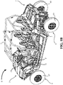
FIG. 1A illustrates a first perspective view of an exemplary vehicle of the present invention; -
FIG. 1B illustrates another perspective view of the exemplary vehicle ofFIG. 1A ; -
FIG. 1C illustrates yet another perspective view of the exemplary vehicle ofFIG. 1A ; -
FIG. 2A illustrates an exemplary vehicle of the present invention -
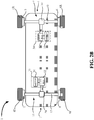
FIG. 2B illustrate an exemplary vehicle of the present invention -
FIG. 3A illustrates an operation of a drive control system of the present invention -
FIG. 3B illustrates an operation of a drive control system based on movement characteristics of a vehicle and operator input commands; -
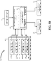
FIG. 3C illustrates an operation of a drive control system based on movement characteristics of a vehicle and operator input commands such as vehicle speed, engine load, electric motor speed, states of charge, drive mode, and braking input; -
FIG. 3D illustrates an exemplary processing sequence of a drive control system of vehicle of the present invention -
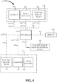
FIG. 4 illustrates an exemplary electrical system suitable for use with the present invention; and -
FIG. 5 illustrates an exemplary graph of the cost to shift power from the ideal split according to an embodiment of the invention. - Corresponding reference characters indicate corresponding parts throughout the several views. Although the drawings represent embodiments of the present invention, the drawings are not necessarily to scale and certain features may be exaggerated in order to better illustrate and explain the present invention. The exemplification set out herein illustrates exemplary embodiments of invention in various forms, and such exemplifications are not to be construed as limiting the scope protection which is defined by the claims.
- The embodiments disclosed below are not intended to be exhaustive or limit the invention to the precise form disclosed in the following detailed description. Rather, the embodiments are chosen and described so that others skilled in the art may utilize their teachings.
-
FIGS. 1A and1B illustrate various perspective views ofvehicle 1 having afront portion 2 and arear portion 4.Vehicle 1 may include side-by side seating as shown with driver's-seat 5 andfront passenger seat 7 and also with rear passenger seats 13 supported by chassis orframe 3 and protected by aroll cage 21. The frame is not particularly limited and may be any conventional frame or any frame developed hereafter capable for packaging and mounting purposes. For example, suitable frames include chassis capable of handling two independent drivetrains and, in some embodiments, in substantially similar ways. -
Frame 3 may be supported by at least one frontground engaging member 6F and at least one rearground engaging member 6R, such aswheels 6. Directional operator actuatable input interfaces may includesteering wheel 19 and operator actuatable torque input interfaces may includeacceleration pedal 17 and brake pedal 18 (both shown inFIG. 1B ) to help control movement ofvehicle 1. -
FIG. 1C illustrates a top-view ofvehicle 1 to further illustrate an exemplary position of various components withinvehicle 1 supported byframe 3.Front driveline 11 may be located forward of first power source 20 (exemplified as being below driver's-seat 5 and front passenger seat 7) whilerear driveline 9 may be located aft of rear power source 40 (exemplified as being below rear passenger seats 13).Front driveline 11 may be in mechanical communication with the forwardground engaging member 6F through drive shafts or other mechanical connections to power movement ofvehicle 1 relative to the ground whilerear driveline 9 may be in mechanical communication with rearground engaging member 6R through drive shafts or other mechanical connections to power movement ofvehicle 1 relative to the ground. -
FIG. 2A illustrates components of an operational control system ofexemplary vehicle 1.Vehicle 1 may include afirst drive system 23 supported by theframe 3.First drive system 23 illustratively includes afirst power source 20 and afront driveline 11 operatively coupled tofirst power source 20 and at least one front ground engaging member (illustrated aswheels 6F).Front driveline 11 communicates power fromfirst power source 20 to at least one frontground engaging member 6F. - Similarly,
second drive system 25 may include asecond power source 40 supported by theframe 3 and arear driveline 9 operatively coupled tosecond power source 40 and at least one rearground engaging member 6R.Rear driveline 9 communicates power fromsecond power source 40 to at least one rearground engaging member 6R. -
Vehicle 1 may also comprise at least one controller (exemplified as controller 15) operatively coupled tofirst drive system 23 andsecond drive system 25.Controller 15 may receive a torque request input from an operator actuatable torque interface adapted to be actuatable by an operator of the vehicle (e.g., fromaccelerator 17 and/or brake 18 shown inFIG. 1B ). The torque request input may provide an indication of a requested torque to the at least onecontroller 15.Controller 15 may be configured to - based on a requested torque - command a first output offirst drive system 23 for the at least one frontground engaging member 6F and a second output ofsecond drive system 25 for the at least one rearground engaging member 6R. -
Front driveline 11 is operatively coupled tofirst power source 20.Rear driveline 9 operatively coupled tosecond power source 40. Controller 15 (e.g., a vehicular control unit or VCU) may be in electrical communication withfront driveline 11,first power source 20,rear driveline 9, andsecond power source 40. For example, as illustrated inFIG. 2A ,controller 15 may be in electrical communication withfirst power source 20 via first power source-controller connection 26. Similarly,controller 15 may be in electrical communication withsecond power source 40 via second power source-controller connection 46.Controller 15 may be configured to controlfront driveline 11 andrear driveline 9 using only power fromfirst power source 20 andsecond power source 40, respectively. -
First power source 20 andsecond power source 40 provide power tofront driveline 11 andrear driveline 9, respectively. In one embodiment,first power source 20 exclusively provides power to one of thefront driveline 11 andrear driveline 9 while second power source exclusively provides power to the other of thefront driveline 11 andrear driveline 9. Exemplary power sources include batteries, capacitors, and other energy storage devices. For example in various embodiments,first power source 20 is an electrical power source with electrical power provided by a first power storage system, exemplified as a first battery bank comprising a plurality of batteries, such as battery 22 (illustratively one of four batteries inFIG. 2A ). Similarly,second power source 40 is an electrical power source with electrical power provided by a second power storage system, exemplified as a second battery bank comprising a plurality of batteries, such as rear battery 42 (illustratively one of four batteries inFIG. 2A ). In various embodiments, a battery cell type of the first battery bank is distinct from the second battery bank. In other words,first battery 22 andsecond battery 42 utilize different structures for storing charge, such as different battery chemistries. Exemplary battery chemistries include lithium-ion, nickel metal hydride, lead- acid, and other suitable chemistries. - As used herein, the term "power storage system" is not particularly limited and may include any power storage system capable of accumulating energy from a form that is more difficult to store to a form that is more conveniently or more economically storable. Exemplary power storage systems include batteries (electrochemical cells), chemical cells (e.g., hydrogen fuel cells, hydrogen peroxide cells), capacitors, and superconducting magnetic energy storage (SMES) systems.
- As used herein, the term "battery" or "battery bank" is not limited to a particular type and may include any suitable type of electrochemical cells. Exemplary suitable electrochemical cells may include cells with varying chemical processes and designs, including galvanic cells, electrolytic cells, fuel cells, flow cells, supercapacitors and voltaic piles. For example, suitable batteries may include lead-acid batteries and lithium-ion batteries.
- For example, in various embodiments, the battery cell type of the first battery bank is lithium-ion batteries and the battery type of the second battery bank is lead-acid batteries. In various aspects, the varying of the chemistries of the first battery bank and the second battery bank allows for
vehicle 1 to have the advantages of multiple battery types. For instance, by having multiplebattery types vehicle 1 may allow for more precise control and regenerative charging of the vehicle's power source, while maintaining sufficient torque output and minimizing total battery bank financial costs. - Referring to
FIG. 2A ,vehicle 1 illustratesbrakes 8 associated withwheels 6. In various embodiments, at least a portion ofbrakes 8 are configured to recover energy from a braking ofvehicle 1 and to electrically provide the recovered energy tofirst power source 20 viaregenerative braking connection 27. Further or alternatively,vehicle 1 may include electric motors, illustratively frontelectric motor 14 and rearelectric motor 16, which may be configured to recover energy during a slowing ofvehicle 1. - The control strategies disclosed herein may be used with electric motors and may combine four functions to help provide torque to drivetrains and help recover energy through regenerative braking or recuperation. The four functions include providing energy to recharge at least one of
first power source 20 andsecond power source 40 during braking, imparting torque to at least one offront driveline 11 andrear driveline 9, allow at least one offront driveline 11 andrear driveline 9 to coast, and reduce jolting during acceleration. One suitable electric motor is the 48 V boost recuperation machine commercially available from the Robert Bosch GMBH, a registered German corporation located atPostfach 30 02, 40 70442 Stuttgart, Germany. Frontelectric motor 14 is shown being coupled topower source 20 throughelectrical connection 24 and may provide recovered energy from braking topower source 20 through frontelectrical connection 24. - Thus, in some embodiments, front
electric motor 14 may provide a source of regenerative braking forfirst power source 20. In various embodiments, some advantages, amongst others, of using an electric motor may include reduced weight and complexity of the various drivelines. For example, in some embodiments, frontelectric motor 14 may be air cooled and, thus, no additional cooling system is required. -
FIG. 2B illustratesvehicle 1 withforward powertrain 30.Powertrain 30 may compriseforward motor 34 in mechanical communication withforward gear box 32 and forward differential 38.Rear powertrain 31 may includerear motor 35 in mechanical communication withrear gear box 33, which may be in mechanical communication withdifferential 39. In one embodiment, both offorward motor 34 andrear motor 35 are electric motors, such aselectric motors first power source 20 andsecond power source 40, respectively. - In various embodiments, the regenerative braking may be controlled by
controller 15. As explained herein,controller 15 controls the operation ofvehicle 1 and performs various tasks. Embodiments ofcontroller 15 may be implemented in hardware, software, firmware, and/or a combination thereof. Further,controller 15 may include any suitable processing device or devices operative to execute the software/firmware stored in memory (not shown). For example,controller 15 may include one or more programmable processors (e.g., central processing unit (CPU) devices), application-specific integrated circuits (ASICs), field-programmable gate arrays (FPGAs), digital signal processors (DSPs), hardwired logic, or combinations thereof. Programming code according to the embodiments can be implemented in any viable programming language such as C, C++, XTML, JAVA or any other viable high-level programming language, or a combination of a high-level programming language and a lower level programming language. - In some embodiments,
controller 15 determines an optimized forward torque forfront drivetrain 11 and/or an optimized rear torque forrear drivetrain 9 based on at least one of a total torque command or a speed of the vehicle. In some embodiments,controller 15 determines at least one of the optimized forward torque or the optimized rear torque based on a state of charge of at least one of the first power source or the second power source. Further, in some embodiments,controller 15 may determine at least one of the forward torque or the rear torque based on a braking command. As used herein the term "optimized" relates to an improvement, but not necessarily the highest degree of improvement. - Similarly, in some embodiments, the
controller 15 include a low-pass filter to filter out small variations in the applied torque to thefront drivetrain 11 and therear drivetrain 9. In some aspects, the use of a low-pass filter may prevent jolting and/or torque spikes. Furthermore, in some embodiments, the use of a low-pass filter may also improve the user control of the vehicle. -
FIG. 3A shows an operation of adrive control system 50. Drivecontrol system 50 receives a torqueinput request command 66 and at least onevehicle characteristic 400. Thedrive control system 50 may then determine an optimized torque withcontroller 15, illustrated as optimizedsplit control circuit 60 ofcontroller 15. The total torque requested in torqueinput request command 66 may then be split between a firsttorque output command 97 to a first power system, such asfirst drive system 23, to provide a first torque output, and a secondtorque output command 95 to a second power system, such assecond drive system 25, to provide a second torque output. - In one embodiment, at least one vehicle operating characteristic 400 may be selected from a vehicle movement characteristic, a vehicle load characteristic or an operator input command and used with the
torque input command 66 to determine afront torque command 97 and arear torque command 95 by the optimizedsplit control circuit 60. Exemplary vehicle movement characteristics include vehicle speed, electric motor speed, state of charge of battery system, and other suitable characteristics. Exemplary vehicle load characteristics include vehicle weight, electric motor operating ranges, and other suitable characteristics. Exemplary operator input commands include changes in the position of theaccelerator pedal 17, changes in the position ofbrake pedal 18, drive mode input position, drivetrain/gear selection input, traction control selection input, and other suitable characteristics.FIG. 3B shows an exemplary embodiment where a movement characteristic 410, a vehicle load characteristic 411 and multiple operator input commands 420 are provided to the optimizedsplit control circuit 60 along withtorque input command 66 to determine afront torque command 97 and arear torque command 95. -
FIG. 3C illustrates an exemplary embodiment where the optimizedsplit control circuit 60 determines a front torquecommand torque command 95 and arear torque command 97 based ontorque input command 66, avehicle speed 401, anengine load 402, an electric motor speed 403, a state ofcharge 404 of a rear battery bank being used assecond power source 40, a state ofcharge 405 of a front battery bank being used asfirst power source 20, adrive mode input 406, and abrake input 407. Thebrake input 407 may be used by a filtering/splitting control circuit 90 of optimizedsplit control circuit 60 to determine whether a braking command or a torque increase command should be given asfront torque command 97 andrear torque command 95. -
FIG. 3D illustrates anexemplary processing sequence 55 of the optimizedsplit control circuit 60 to determine split torque commands of a vehicle, such asvehicle 1. Split torquecommand processing sequence 55 may include receiving atorque input command 66 and a signal indicating a speed of a vehicle, such as the front electric motor speed 67 from frontelectric motor 14. - Optimized
split control circuit 60 determines anideal split 68 of a requested torque into a front torque output command and a rear torque output command based on atotal torque command 66 and an electric motor speed 67. The front torque output command is for thefront drive system 23 and the rear torque output command is for therear drive system 25. In some embodiments, the ideal split is determined based on the minimization of the total losses for the entire vehicle driving system at a given operating condition (e.g., speed of the vehicle). This determination may include both the electric motor losses and the battery losses for both the front and rearelectric motors vehicle 1 at a given total torque demand. Thus, the total system loss at a given torque may be provided as the sum of the (i) front electric motor losses, (ii) the rear electric motor losses, (iii) the front battery losses, (iv) the rear battery losses, and (v) losses associated with any mechanical linkages to the ground engaging members at the given torque. - Because electric motor losses at a given torque and speed can be analyzed and measured, their losses may be determined using an efficiency map of the motor. The battery losses at a given torque and speed can be determined by calculating the power to be requested by the electric motor at the expected operating point of the electric motor and then based on that expected power draw, the expected battery loss. In one example, the battery may be modeled as an ideal voltage source in series with an internal resister. Using this model, the following equation may be used to determine or approximate the battery loss:

- Using the aforementioned equation and an efficiency map, a look-up table may be created for all possible electric motor speed and requested torque combinations. For each requested torque input and measure vehicle speed (electric motor speed), the look-up table may provide the (i) front electric motor losses, (ii) the rear electric motor losses, (iii) the front battery losses, and (iv) the rear battery losses from which the ideal split may be determined. For example, optimized
split control circuit 60 may sum the retrieved losses and select the split that provides the minimum loss. Alternatively, the look-up table may provide for each requested torque input and measured vehicle speed (electric motor speed), the ideal split for the front torque output command and the rear torque output command. For example, the look-up table for a first given requested torque and a first measured vehicle speed may provide a split of 60% front torque command/40% rear torque command which provides the lowest system losses for the first given requested torque and the first measured vehicle speed and for a second given requested torque and the first measure vehicle speed a split of 45% front torque command/55% rear torque command which provides the lowest system losses for the second given requested torque and the first measured vehicle speed. While the split values can range from 0% to 100%, in some combinations, the split values could range from a torque split of the front torque being about 20% to about 80% of the total torque output command, about 40% to about 80% of the total torque output command, about 40% to about 60% of the total torque output command, or about 60% to about 80% of the total torque output command. In one example the ideal split 68 is set at a constant value for all possible electric motor speeds and requested torque inputs. In one example, the constant value is about 54%. - In the illustrated
processing sequence 55, the determined split value for the front torque output command and the rear torque output command determined byideal split 68 may be modified by theSOC correction shift 63. Based on a state of charge (SOC) of a first power source 62 (power source 20), a SOC of a second power source 64 (power source 40), the determined split value fromideal split 68, and a cost to shiftdetermination 65, optimized idealsplit control circuit 60 may make aSOC correction shift 63. - In one embodiment,
SOC correction shift 63 shifts the torque split point to prevent drain of one of the twobattery systems 22 and 42 (seeFIG. 2A ). In one embodiment, SOC correction shift shifts the torque split point to intentionally drainbatteries 22. One reason for this, whenbatteries 22 are lithium-ion batteries andbatteries 42 are lead-acid batteries, is that lithium-ion batteries are able to handle a larger in-rush of current than lead-acid batteries. Thus,batteries 22 are better suited to receive energy recovered through regenerative braking thanbatteries 42. In order to maximize the ability to use recovered energy for recharging the batteries ofvehicle 1,batteries 22 should have a state-of-charge level to receive the recovered energy. However, shifting away from the ideal split results is additional energy losses. Optimizedsplit control circuit 60 thus looks at the cost, additional energy loss, for shifting from the determinedideal split point 68. - The cost to shift
determination 63, in one embodiment, is the cost or power loss to shift torque split point from the ideal split based on the current operating conditions. Similar to the ideal split determination, determination of the cost to shift may be accomplished by calculating the power loss (e.g., electrical watts) above the power losses at the ideal split for every potential operating point. - The extra electrical watts lost above the ideal split at the operating point per watt shifted was found to roughly fit a curve having the following equation: y = C ∗ x 2, where C is a constant at a given speed and torque load.
FIG. 5 illustrates agraph 500 including some exemplary cost to shift torque data from optimal according to one embodiment. The data inFIG. 5 corresponds to a speed of 3,000 rpm and a torque of 50 (Nm). The value of constant (C) may be determined by fitting a quadratic function to the illustrated data. The x-axis inFIG. 5 corresponds to the number of Watts to be shifted from thefront drive system 23 to therear drive system 25. The negative values correspond to power shifted from thefront drive system 23 to therear drive system 25 and the positive values correspond to power shifted to thefront drive system 23 from therear drive system 25. - Assuming both
batteries 22 andbatteries 42 are not fully charged, optimizedsplit control circuit 60 may establish a set point to guide when changes from the ideal split are desired based on a difference inSOC 62 ofbatteries 42 andSOC 64 ofbatteries 22. In one embodiment, if the difference is below a first set point then no shifting from ideal is to occur. Further, if the difference is above the first set point then shifting should occur to better balance the charge betweenbatteries 22 andbatteries 42. Thus, in various embodiments,controller 15 may alter split between the first torque command and the second torque command based on a charge difference between theforward battery bank 22 and therear battery bank 42 being greater than a predetermined threshold. While the deviation decision may be binary, the predetermined threshold may be a percent charge difference. In various embodiments, the predetermined threshold may be when the percentage charge difference is greater than about 10%, greater than about 7.5%, or greater than about 5%. -
Controller 15 may determine the appropriate amount of torque to shift by combining the degree of difference there is in pack SOC values and the cost to shift determination. The decision to shift torque to rebalance SOC may determined by two set points: the lower set point (e.g., the point at which the control will start to do some shifting, for example, about 2% difference) and the higher set point (e.g., the point above which the control will attempt to shift all of the torque, for example, about a 5% difference). The constant value C found at each operating point provides an indication of the cost to shift at a given operating point. These two factors (SOC difference and C value) may be fed into a 2-input 1-output calibratable map, which may generate the percent of torque to shift from one powertrain to the other. The map may reflect the percentage of torque to shift away from the ideal split, thus, as the C value increases, the controller may be less willing to shift torque when the SOC value is between the two SOC set points. The axes the 2-input 1-output calibratable map may include the normalized difference in the SOC between two set points (x-axis), the C value (y-axis), and the dependent variable axis (z-axis). Exemplary dependent variable axis values include the percentage of torque to shift. -
Controller 15 next verifies that the determined split is within the performance limits of the systems ofvehicle 1 with aperformance correction 61. In one example,controller 15 determines the operating revolutions per minute of frontelectric motor 14 and rearelectric motor 16 to verify that the requested increase in output is within the operating range of frontelectric motor 14 and rearelectric motor 16. If so, then no change is made to the split value. If not, the split value is adjusted to maintain frontelectric motor 14 and rearelectric motor 16 within their respective operating ranges. - Split torque
command processing sequence 55 may also contain an electricalbraking architecture strategy 80, which may be configured to receive a brake command, determine an optimized braking torque split between thefront driveline 11 and therear driveline 9. In various embodiments, the braking torque split determination may be combined with the total torque demand and may be used as to make a brake/acceleration torque determination 98 that is part of the filtering/splitting architecture 90. In one example, brake/acceleration torque determination 98 may receive a split from optimizedsplit control circuit 60 that is 30% to frontelectric motor 14, but since the request is a braking request, brake/acceleration torque determination 98 may alter the split to be more to frontelectric motor 14 to recover additional energy from regenerative braking andcharge batteries 22. - In the filtering/
splitting architecture 90, the totaltorque input demand 66 and the braking torque splitdetermination 82 may be received. If the signal of a torque command and the speed of the vehicle (e.g., electric motor speed 67) match then the request may be an accelerating torque. If they do not match then the request may be a braking torque. In some embodiments, around a zero speed point, a transition zone may be implemented to prevent step changes in the split. Within this zone, a linear interpolation between the first section's split and the second section's split may be performed. The size of this zone may be determined by two calibratable labels. After the split is determined, the final torque requests is through low pass filters, one for each motor, immediately before being transmitted to the motors in order to provide acceptable noise, vibration, and harshness (NVH) characteristics. - In additions to systems, various embodiments of methods of managing a plurality of independent battery banks in a vehicle are disclosed herein. Such methods may include receiving, by a controller a forward state of charge of a forward battery bank over a first communication network (such as a control area network), receiving a rear state of charge of a rear battery bank over a second communication network, determining and in response to a torque request, a first torque command and a second torque command, outputting the first torque command over the first communication network, and outputting the second torque command over the second communication network. In various embodiments, the first communication network may be independent of the second communication network or they may form part of the same communication network. The communication network or communication networks may use control area network (CAN) protocol, which may be specified as International Standards Organization standard 11898. The communication network or bus may be a digital system that may use (or form) a single-wire, twisted pair wires, a two-wire connection, a three-wire connection, fiber optic connections or other suitable types of hardware and combinations thereof.
-
FIG. 4 illustrates the electrical architecture of a battery management system according to various embodiments of this disclosure.Battery management system 100 may include a forward battery bank that may include one or morefront batteries 106 and a rear battery bank that may include one or morerear batteries 116. In some embodiments, the voltage capacity of the front batteries and the rear batteries may differ and in other embodiments, the voltage capacity may be the same. In various embodiments, the front battery bank and the rear battery bank are electrically independent from each other. Thus, controller 105 (such as a vehicular control unit (VCU)) may independently and separately manage the front battery bank and the rear battery bank. For example, in some embodiments, a first communication network (such as a control area network) 101 may connect the forward battery bank including one ormore batteries 106 tocontroller 105 and a second communication network 111 may connect the rear battery bank including one ormore batteries 116 tocontroller 105. In various embodiments,controller 105 may output a first torque command overfirst communication network 101 and a second torque command oversecond communication network 102 in response to a torque request. -
Battery management system 100 may also comprise a front power system 102 (e.g., a 48 volt system).Front power system 102 may comprisecharger 104, front battery bank including one ormore batteries 106, and frontelectric motor 108. Similarly,battery management system 100 may comprise arear power system 110.Rear power system 110 may comprise a rearelectric motor 112, acharger 114, and rear battery bank including one ormore batteries 116. - In addition to being electrically connected to
front power system 102 andrear power system 110,controller 105 may be electrically connected to an electric power assisted steering (EPAS)system 120 overthird communication network 121. Also,first communication network 101 may also connect adisplay 103 to thecontroller 105.Display 103 may be provided on a dash ofvehicle 1 and positioned to be observable by an operator ofvehicle 1. - As shown in
FIG. 4 battery management system may manage thefront power system 102 and therear power system 110. Althoughfront power system 102 andrear power system 110 are each exemplified with afront battery 106 and arear battery 116, both thefront power system 102 and therear power system 110 may include a plurality of batteries in parallel or in series. This, battery management system may be configured to manage a plurality of independent battery banks in a vehicle.Controller 105 may be configured to receive a forward state of charge of forward batterybank including batteries 106 over afirst communication network 101 and receive a rear state of charge of rear batterybank including batteries 116 over asecond communication network 102. - Furthermore,
controller 105 may be configured to determine—in response to a torque request—a first torque command and a second torque command and output the first torque command over thefirst communication network 101 and output the second torque command over thesecond communication network 102. As shown inFIG. 4 , the two networks may be electrically independent of the other network, or in other words, the first communication network and the second communication network do not share or directly transfer electricity, but may both be controlled by thesame controller 105. -
FIG. 4 also illustrates vehicle drive control system for a vehicle having a first power system (front power system 102) and a second power system (rear power system 110).Controller 105 may also be configured to receive a torque input command, receive at least one vehicle characteristic, provide a first torque output command to the first power system (illustrated as front power system 102) to provide a first torque output (via front electric motor 108), and provide a second torque output command to the second power system (rear power system 110) to provide a second torque output (e.g., via rear electric motor 112). In one embodiment,controller 105 may operate in accordance with the discussions herein relative tocontroller 15 andprocessing sequence 55. - The drive control system may also comprise a
first connector 151 operably coupled to thecontroller 105 and adapted to be operably coupled to afirst communication network 101 connecting the first power system (illustrated as front power system 102) tocontroller 105. Similarly, asecond connector 152 may also be operably coupled to thecontroller 105 and adapted to be operably coupled to a second communication network 111 connecting the second power system (illustrated as rear power system 110) andcontroller 105.
Claims (15)
- A vehicle drive control system (50) for a vehicle (1) having a first drive system (23) including a first battery bank (22) and a second drive system (25) including a second battery bank (42), comprising:at least one controller (15) configured to:receive a torque input command,receive at least one vehicle characteristic,provide a first torque output command to the first drive system (23) to provide a first torque output,provide a second torque output command to the second drive system (25) to provide a second torque output;a first connector (151) operably coupled to the controller (15) and adapted to be operably coupled to a first communication network (101) connecting the first drive system (23) to the at least one controller (15); anda second connector (152) operably coupled to the controller (15) and adapted to be operably coupled to a second communication network (111) connecting the second drive system (25) and the at least one controller (15), characterised in that the at least one controller (15) is configured to:receive an indication of a state of charge of the first battery bank (22) of the first drive system (23) and an indication of a state of charge of the second battery bank (42) of the second drive system (25), andalter at least one of the first torque output command or the second torque output command based on a charge difference between the state of charge of the first battery bank (220 and the state of charge of the second battery bank (42) being greater than a predetermined threshold.
- The vehicle drive control system (50) of claim 1, wherein the predetermined threshold is a percent charge difference.
- The vehicle drive control system (50) of claim 2, wherein the predetermined threshold is greater than about 5%, preferably greater than about 7.5%, and more preferably greater than about 10%.
- The vehicle drive control system (50) of any of claims 1-3, wherein the controller (15) is configured to receive the torque input command from at least one of an accelerator pedal (17) or a brake pedal (18).
- The vehicle drive control system (50) of any of claims 1-4, wherein the at least one controller (15) comprises a low-pass filter configured to alter at least one of the first torque output command or the second torque output command.
- The vehicle drive control system (50) of any of claims 1-5, wherein the first torque output command is between about 20% to about 80% of a total torque output command comprising the first torque output command and the second torque output command.
- The vehicle drive control system (50) of any of claims 1-6, wherein the first torque output command is between about 20% to about 60% of the total torque output command.
- The vehicle drive control system (50) of any of claims 1-7, wherein the first torque output command is between about 40% to about 80% of the total torque output command.
- The vehicle drive control system (50) of any of claims 1-8, wherein the first torque output command is between about 40% to about 60%, preferably between about 50% to about 60% of the total torque output command
- The vehicle drive control system (50) of any of claims 1-9, wherein the first torque output command is about 54% of the total torque output command.
- The vehicle drive control system (50) of any of claims 1-10, wherein the first torque output command and the second torque output command are determined to minimize the loss of power between the first battery bank (22), the second battery bank (42), and a travel surface.
- A vehicle (1) comprising the vehicle drive control system (50) of any of claims 1-11.
- The vehicle (1) of claim 12, wherein the first drive system (23) of the vehicle (1) further includes a front driveline (11) operatively coupled to the first battery bank (22); the second drive system (25) of the vehicle (1) further includes a rear driveline (9) operatively coupled to the second battery bank (42); the at least one controller (15) is in electrical communication with the first drive system (23) and the second drive system (25); and the front driveline (11) and the first battery bank (22) are independent of the rear driveline (9) and the second battery bank (42).
- The vehicle (1) of claim 14, wherein the first battery bank (22) includes a plurality of lithium-ion batteries.
- The vehicle (1) of claim 13 or 14, wherein the second battery bank (42) includes a plurality of lead-acid batteries.
Applications Claiming Priority (2)
| Application Number | Priority Date | Filing Date | Title |
|---|---|---|---|
| US15/278,926 US10647324B2 (en) | 2016-09-28 | 2016-09-28 | Systems and methods for control of two independent powertrains in a vehicle |
| PCT/US2017/053883 WO2018064258A1 (en) | 2016-09-28 | 2017-09-28 | Systems and methods for control of two independent powertrains in a vehicle |
Publications (2)
| Publication Number | Publication Date |
|---|---|
| EP3519223A1 EP3519223A1 (en) | 2019-08-07 |
| EP3519223B1 true EP3519223B1 (en) | 2021-10-27 |
Family
ID=60051589
Family Applications (1)
| Application Number | Title | Priority Date | Filing Date |
|---|---|---|---|
| EP17781605.5A Active EP3519223B1 (en) | 2016-09-28 | 2017-09-28 | Vehicle drive control system and vehicle |
Country Status (8)
| Country | Link |
|---|---|
| US (1) | US10647324B2 (en) |
| EP (1) | EP3519223B1 (en) |
| CN (1) | CN109789758A (en) |
| AU (3) | AU2017335774B2 (en) |
| CA (1) | CA3038507C (en) |
| ES (1) | ES2905303T3 (en) |
| MX (1) | MX2019003051A (en) |
| WO (1) | WO2018064258A1 (en) |
Cited By (1)
| Publication number | Priority date | Publication date | Assignee | Title |
|---|---|---|---|---|
| EP4434784A1 (en) * | 2023-03-22 | 2024-09-25 | Polaris Industries Inc. | Electric all-terrain vehicle |
Families Citing this family (19)
| Publication number | Priority date | Publication date | Assignee | Title |
|---|---|---|---|---|
| US10647324B2 (en) | 2016-09-28 | 2020-05-12 | Polaris Industries Inc. | Systems and methods for control of two independent powertrains in a vehicle |
| FR3081392A1 (en) * | 2018-05-28 | 2019-11-29 | Valeo Equipements Electriques Moteur | HYDROGEN TRACTION ARCHITECTURE FOR MOTOR VEHICLE |
| JP7003863B2 (en) * | 2018-07-20 | 2022-02-04 | トヨタ自動車株式会社 | Vehicle controls, control methods and control programs |
| US11453309B2 (en) * | 2018-09-06 | 2022-09-27 | Artisan Vehicle Systems, Inc. | Electric power distribution system and method for electric mining machine |
| JP2020117148A (en) * | 2019-01-25 | 2020-08-06 | ヤマハ発動機株式会社 | Open cabin electric vehicle |
| EP3760471B1 (en) * | 2019-07-02 | 2024-11-13 | Polestar Performance AB | Dual battery system for electric vehicle |
| EP4007705A4 (en) * | 2019-08-01 | 2023-08-16 | System73 Limited | MULTI-MOTOR AND PROCESS COMMUTATION SYSTEM FOR OPTIMIZED PERFORMANCE |
| EP3771587B1 (en) * | 2019-08-01 | 2023-06-07 | Nokian Raskaat Renkaat Oy | All-terrain vehicle and control arrangement for the same |
| CN113715597B (en) * | 2020-05-21 | 2023-02-03 | 华为数字能源技术有限公司 | Powertrains and Vehicles |
| USD960807S1 (en) | 2021-01-08 | 2022-08-16 | Polaris Industries Inc. | Door for an off-road vehicle |
| US20220379872A1 (en) * | 2021-05-26 | 2022-12-01 | Ford Global Technologies, Llc | Electrified vehicle control with distribution of powertrain torque to secondary axle |
| WO2023044439A1 (en) * | 2021-09-17 | 2023-03-23 | Polaris Industries Inc. | Electric all-terrain vehicle |
| US12148962B2 (en) | 2021-12-01 | 2024-11-19 | Toyota Motor Engineering & Manufacturing North America, Inc. | Modular fuel cell system architecture and a control system for distributing power to the modules |
| US11987257B2 (en) | 2021-12-01 | 2024-05-21 | Toyota Motor Engineering & Manufacturing North America, Inc. | Drive system controls architecture for OEM interface and services |
| US12365295B2 (en) | 2021-12-01 | 2025-07-22 | Toyota Motor Engineering & Manufacturing North America, Inc. | Modular fuel cell system architecture and harness |
| WO2023230995A1 (en) * | 2022-06-02 | 2023-12-07 | 宁德时代新能源科技股份有限公司 | Battery regulation system, method and electric apparatus using same |
| US12612031B2 (en) * | 2023-12-01 | 2026-04-28 | Fca Us Llc | Optimal electric motor torque actuation in hybrid and electric propulsion systems at low torque requests |
| KR20250178874A (en) * | 2024-06-20 | 2025-12-29 | 현대자동차주식회사 | Method for controlling battery for an electric vehicle, controller, and electric vehicle |
| TWI897787B (en) * | 2024-12-31 | 2025-09-11 | 城市學校財團法人臺北城市科技大學 | Self-electrolyzed sustainable hydrogen energy brushless direct current motor |
Family Cites Families (25)
| Publication number | Priority date | Publication date | Assignee | Title |
|---|---|---|---|---|
| DE102004026237A1 (en) | 2004-02-11 | 2005-11-10 | Rheinmetall Landsysteme Gmbh | Vehicle with protection against the action of a landmine |
| CN101484328A (en) * | 2006-04-03 | 2009-07-15 | 布卢沃夫系统责任有限公司 | Vehicle power unit designed as retrofittable axle comprising motor, battery and suspension |
| EP2225118B1 (en) | 2007-12-12 | 2016-06-22 | Foss Maritime Company | Hybrid propulsion systems |
| DE102008019656A1 (en) | 2008-04-18 | 2009-10-22 | Krauss-Maffei Wegmann Gmbh & Co. Kg | Military motor vehicle |
| DE102008020555A1 (en) | 2008-04-22 | 2009-10-29 | Esw Gmbh | Redundant drive system for hybrid driven vehicle e.g. military all-terrain vehicle, has set of electrical machines alternatively separated from mechanical drive strand of internal combustion engine or wheel drive unit |
| US20110020221A1 (en) * | 2009-04-09 | 2011-01-27 | The Johns Hopkins University | Cancer stem cell expression patterns and compounds to target cancer stem cells |
| JP2011251579A (en) | 2010-05-31 | 2011-12-15 | Nobuyoshi Muto | Electric vehicle and program |
| US9027682B2 (en) * | 2013-02-01 | 2015-05-12 | Daniel James LAMBERT | Self charging electric vehicle |
| CN103386895B (en) * | 2013-07-26 | 2017-08-29 | 浙江吉利汽车研究院有限公司 | Four-drive electric car |
| CN203752866U (en) * | 2014-01-16 | 2014-08-06 | 浙江吉利控股集团有限公司 | Time-sharing four-wheel driving electric vehicle power system and electric vehicle |
| US10206584B2 (en) * | 2014-08-08 | 2019-02-19 | Medlumics S.L. | Optical coherence tomography probe for crossing coronary occlusions |
| JP6075355B2 (en) * | 2014-11-07 | 2017-02-08 | トヨタ自動車株式会社 | Automobile |
| KR20170072935A (en) * | 2014-12-16 | 2017-06-27 | 비와이디 컴퍼니 리미티드 | Electric vehicle, active safety control system of electric vehicle, and control method therefor |
| US9960458B2 (en) * | 2015-06-23 | 2018-05-01 | Quantumscape Corporation | Battery systems having multiple independently controlled sets of battery cells |
| KR20170008083A (en) * | 2015-07-13 | 2017-01-23 | 에스케이하이닉스 주식회사 | Refresh verification circuit, Semiconductor Apparatus and Semiconductor System |
| JP6298037B2 (en) * | 2015-12-24 | 2018-03-20 | トヨタ自動車株式会社 | Driving device control system |
| JP6414044B2 (en) * | 2015-12-25 | 2018-10-31 | トヨタ自動車株式会社 | Vehicle driving force control device |
| US10717361B2 (en) * | 2016-01-19 | 2020-07-21 | Kubota Corporation | Work vehicle and display device for the work vehicle |
| JP6380429B2 (en) * | 2016-03-02 | 2018-08-29 | トヨタ自動車株式会社 | Automobile |
| JP6439722B2 (en) * | 2016-03-08 | 2018-12-19 | トヨタ自動車株式会社 | Hybrid car |
| JP6681002B2 (en) * | 2016-03-30 | 2020-04-15 | 三菱自動車工業株式会社 | Power control device for hybrid vehicle |
| JP6418196B2 (en) * | 2016-04-15 | 2018-11-07 | トヨタ自動車株式会社 | Electric car |
| US9758040B1 (en) * | 2016-07-22 | 2017-09-12 | Textron Inc. | Prime mover RPM limiting control |
| JP6588406B2 (en) * | 2016-08-12 | 2019-10-09 | トヨタ自動車株式会社 | Hybrid car |
| US10647324B2 (en) | 2016-09-28 | 2020-05-12 | Polaris Industries Inc. | Systems and methods for control of two independent powertrains in a vehicle |
-
2016
- 2016-09-28 US US15/278,926 patent/US10647324B2/en active Active
-
2017
- 2017-09-28 CN CN201780057980.0A patent/CN109789758A/en active Pending
- 2017-09-28 ES ES17781605T patent/ES2905303T3/en active Active
- 2017-09-28 AU AU2017335774A patent/AU2017335774B2/en active Active
- 2017-09-28 MX MX2019003051A patent/MX2019003051A/en unknown
- 2017-09-28 EP EP17781605.5A patent/EP3519223B1/en active Active
- 2017-09-28 CA CA3038507A patent/CA3038507C/en active Active
- 2017-09-28 WO PCT/US2017/053883 patent/WO2018064258A1/en not_active Ceased
-
2020
- 2020-01-31 AU AU2020200714A patent/AU2020200714B2/en active Active
-
2021
- 2021-06-21 AU AU2021204163A patent/AU2021204163B2/en active Active
Cited By (1)
| Publication number | Priority date | Publication date | Assignee | Title |
|---|---|---|---|---|
| EP4434784A1 (en) * | 2023-03-22 | 2024-09-25 | Polaris Industries Inc. | Electric all-terrain vehicle |
Also Published As
| Publication number | Publication date |
|---|---|
| AU2020200714B2 (en) | 2021-07-15 |
| US10647324B2 (en) | 2020-05-12 |
| AU2021204163A1 (en) | 2021-07-15 |
| EP3519223A1 (en) | 2019-08-07 |
| CA3038507C (en) | 2021-12-28 |
| WO2018064258A1 (en) | 2018-04-05 |
| CN109789758A (en) | 2019-05-21 |
| ES2905303T3 (en) | 2022-04-07 |
| MX2019003051A (en) | 2019-07-18 |
| CA3038507A1 (en) | 2018-04-05 |
| US20180086343A1 (en) | 2018-03-29 |
| AU2017335774B2 (en) | 2019-10-31 |
| AU2021204163B2 (en) | 2023-02-23 |
| AU2020200714A1 (en) | 2020-02-20 |
| AU2017335774A1 (en) | 2019-05-02 |
Similar Documents
| Publication | Publication Date | Title |
|---|---|---|
| AU2021204163B2 (en) | Systems and methods for control of two independent powertrains in a vehicle | |
| US12187162B2 (en) | Electric vehicle propulsion system and propulsion system operating method | |
| CN111452670B (en) | Battery voltage switching system and control logic for a multi-battery electrically driven vehicle | |
| CN115071738B (en) | Intelligent vehicle and control logic for managing failures in a dual independent drive unit axle powertrain | |
| EP3153368B1 (en) | Method and apparatus for controlling hybrid electric vehicle | |
| CN105848946B (en) | Vehicle and vehicle control method | |
| US11407315B2 (en) | Method for determining a load distribution, control unit, powertrain and motor vehicle | |
| US11577612B2 (en) | System for adjusting regenerative torque according to state of charge of multiple batteries | |
| US20220379872A1 (en) | Electrified vehicle control with distribution of powertrain torque to secondary axle | |
| JP3901009B2 (en) | Electric car | |
| US12172641B2 (en) | Electrified vehicle configured to selectively increase energy recovery threshold and corresponding method | |
| US11654882B2 (en) | Device for controlling driving of an electric four-wheel drive vehicle at the time of shift | |
| JP4380040B2 (en) | Four-wheel drive electric vehicle and control method thereof | |
| JP2017038470A (en) | Electric automobile brake control apparatus | |
| JP6686384B2 (en) | Hybrid vehicle regenerative electric energy control system, hybrid vehicle, and regenerative electric energy control method for hybrid vehicle | |
| JP2002345105A (en) | Electric car | |
| JP6729161B2 (en) | Hybrid vehicle | |
| JP7578080B2 (en) | Electric vehicles | |
| US20250222917A1 (en) | System and method of towing controls for creating a hybrid vehicle from an electric vehicle and a conventional vehicle | |
| CN120462401A (en) | Axle Torque Grade Assist |
Legal Events
| Date | Code | Title | Description |
|---|---|---|---|
| STAA | Information on the status of an ep patent application or granted ep patent |
Free format text: STATUS: UNKNOWN |
|
| STAA | Information on the status of an ep patent application or granted ep patent |
Free format text: STATUS: THE INTERNATIONAL PUBLICATION HAS BEEN MADE |
|
| PUAI | Public reference made under article 153(3) epc to a published international application that has entered the european phase |
Free format text: ORIGINAL CODE: 0009012 |
|
| STAA | Information on the status of an ep patent application or granted ep patent |
Free format text: STATUS: REQUEST FOR EXAMINATION WAS MADE |
|
| 17P | Request for examination filed |
Effective date: 20190416 |
|
| AK | Designated contracting states |
Kind code of ref document: A1 Designated state(s): AL AT BE BG CH CY CZ DE DK EE ES FI FR GB GR HR HU IE IS IT LI LT LU LV MC MK MT NL NO PL PT RO RS SE SI SK SM TR |
|
| AX | Request for extension of the european patent |
Extension state: BA ME |
|
| DAV | Request for validation of the european patent (deleted) | ||
| DAX | Request for extension of the european patent (deleted) | ||
| RIN1 | Information on inventor provided before grant (corrected) |
Inventor name: ERASMUS, PETER J. Inventor name: BLAIR, KEVIN P. Inventor name: BUEHLER, DAVID F. Inventor name: CRAIN, STEPHEN G. Inventor name: HOFFET, MARKUS |
|
| GRAP | Despatch of communication of intention to grant a patent |
Free format text: ORIGINAL CODE: EPIDOSNIGR1 |
|
| STAA | Information on the status of an ep patent application or granted ep patent |
Free format text: STATUS: GRANT OF PATENT IS INTENDED |
|
| RIC1 | Information provided on ipc code assigned before grant |
Ipc: B60W 50/00 20060101ALI20210415BHEP Ipc: B60K 1/04 20190101ALI20210415BHEP Ipc: B60K 1/00 20060101ALI20210415BHEP Ipc: B60K 1/02 20060101AFI20210415BHEP |
|
| INTG | Intention to grant announced |
Effective date: 20210514 |
|
| GRAS | Grant fee paid |
Free format text: ORIGINAL CODE: EPIDOSNIGR3 |
|
| GRAA | (expected) grant |
Free format text: ORIGINAL CODE: 0009210 |
|
| STAA | Information on the status of an ep patent application or granted ep patent |
Free format text: STATUS: THE PATENT HAS BEEN GRANTED |
|
| AK | Designated contracting states |
Kind code of ref document: B1 Designated state(s): AL AT BE BG CH CY CZ DE DK EE ES FI FR GB GR HR HU IE IS IT LI LT LU LV MC MK MT NL NO PL PT RO RS SE SI SK SM TR |
|
| REG | Reference to a national code |
Ref country code: GB Ref legal event code: FG4D |
|
| REG | Reference to a national code |
Ref country code: CH Ref legal event code: EP |
|
| REG | Reference to a national code |
Ref country code: AT Ref legal event code: REF Ref document number: 1441479 Country of ref document: AT Kind code of ref document: T Effective date: 20211115 |
|
| REG | Reference to a national code |
Ref country code: DE Ref legal event code: R096 Ref document number: 602017048337 Country of ref document: DE |
|
| REG | Reference to a national code |
Ref country code: IE Ref legal event code: FG4D |
|
| REG | Reference to a national code |
Ref country code: FI Ref legal event code: FGE |
|
| REG | Reference to a national code |
Ref country code: SE Ref legal event code: TRGR |
|
| REG | Reference to a national code |
Ref country code: LT Ref legal event code: MG9D |
|
| REG | Reference to a national code |
Ref country code: NL Ref legal event code: MP Effective date: 20211027 |
|
| REG | Reference to a national code |
Ref country code: AT Ref legal event code: MK05 Ref document number: 1441479 Country of ref document: AT Kind code of ref document: T Effective date: 20211027 |
|
| REG | Reference to a national code |
Ref country code: ES Ref legal event code: FG2A Ref document number: 2905303 Country of ref document: ES Kind code of ref document: T3 Effective date: 20220407 |
|
| PG25 | Lapsed in a contracting state [announced via postgrant information from national office to epo] |
Ref country code: RS Free format text: LAPSE BECAUSE OF FAILURE TO SUBMIT A TRANSLATION OF THE DESCRIPTION OR TO PAY THE FEE WITHIN THE PRESCRIBED TIME-LIMIT Effective date: 20211027 Ref country code: LT Free format text: LAPSE BECAUSE OF FAILURE TO SUBMIT A TRANSLATION OF THE DESCRIPTION OR TO PAY THE FEE WITHIN THE PRESCRIBED TIME-LIMIT Effective date: 20211027 Ref country code: BG Free format text: LAPSE BECAUSE OF FAILURE TO SUBMIT A TRANSLATION OF THE DESCRIPTION OR TO PAY THE FEE WITHIN THE PRESCRIBED TIME-LIMIT Effective date: 20220127 Ref country code: AT Free format text: LAPSE BECAUSE OF FAILURE TO SUBMIT A TRANSLATION OF THE DESCRIPTION OR TO PAY THE FEE WITHIN THE PRESCRIBED TIME-LIMIT Effective date: 20211027 |
|
| PG25 | Lapsed in a contracting state [announced via postgrant information from national office to epo] |
Ref country code: IS Free format text: LAPSE BECAUSE OF FAILURE TO SUBMIT A TRANSLATION OF THE DESCRIPTION OR TO PAY THE FEE WITHIN THE PRESCRIBED TIME-LIMIT Effective date: 20220227 Ref country code: PT Free format text: LAPSE BECAUSE OF FAILURE TO SUBMIT A TRANSLATION OF THE DESCRIPTION OR TO PAY THE FEE WITHIN THE PRESCRIBED TIME-LIMIT Effective date: 20220228 Ref country code: PL Free format text: LAPSE BECAUSE OF FAILURE TO SUBMIT A TRANSLATION OF THE DESCRIPTION OR TO PAY THE FEE WITHIN THE PRESCRIBED TIME-LIMIT Effective date: 20211027 Ref country code: NO Free format text: LAPSE BECAUSE OF FAILURE TO SUBMIT A TRANSLATION OF THE DESCRIPTION OR TO PAY THE FEE WITHIN THE PRESCRIBED TIME-LIMIT Effective date: 20220127 Ref country code: NL Free format text: LAPSE BECAUSE OF FAILURE TO SUBMIT A TRANSLATION OF THE DESCRIPTION OR TO PAY THE FEE WITHIN THE PRESCRIBED TIME-LIMIT Effective date: 20211027 Ref country code: LV Free format text: LAPSE BECAUSE OF FAILURE TO SUBMIT A TRANSLATION OF THE DESCRIPTION OR TO PAY THE FEE WITHIN THE PRESCRIBED TIME-LIMIT Effective date: 20211027 Ref country code: HR Free format text: LAPSE BECAUSE OF FAILURE TO SUBMIT A TRANSLATION OF THE DESCRIPTION OR TO PAY THE FEE WITHIN THE PRESCRIBED TIME-LIMIT Effective date: 20211027 Ref country code: GR Free format text: LAPSE BECAUSE OF FAILURE TO SUBMIT A TRANSLATION OF THE DESCRIPTION OR TO PAY THE FEE WITHIN THE PRESCRIBED TIME-LIMIT Effective date: 20220128 |
|
| REG | Reference to a national code |
Ref country code: DE Ref legal event code: R097 Ref document number: 602017048337 Country of ref document: DE |
|
| PG25 | Lapsed in a contracting state [announced via postgrant information from national office to epo] |
Ref country code: SM Free format text: LAPSE BECAUSE OF FAILURE TO SUBMIT A TRANSLATION OF THE DESCRIPTION OR TO PAY THE FEE WITHIN THE PRESCRIBED TIME-LIMIT Effective date: 20211027 Ref country code: SK Free format text: LAPSE BECAUSE OF FAILURE TO SUBMIT A TRANSLATION OF THE DESCRIPTION OR TO PAY THE FEE WITHIN THE PRESCRIBED TIME-LIMIT Effective date: 20211027 Ref country code: RO Free format text: LAPSE BECAUSE OF FAILURE TO SUBMIT A TRANSLATION OF THE DESCRIPTION OR TO PAY THE FEE WITHIN THE PRESCRIBED TIME-LIMIT Effective date: 20211027 Ref country code: EE Free format text: LAPSE BECAUSE OF FAILURE TO SUBMIT A TRANSLATION OF THE DESCRIPTION OR TO PAY THE FEE WITHIN THE PRESCRIBED TIME-LIMIT Effective date: 20211027 Ref country code: DK Free format text: LAPSE BECAUSE OF FAILURE TO SUBMIT A TRANSLATION OF THE DESCRIPTION OR TO PAY THE FEE WITHIN THE PRESCRIBED TIME-LIMIT Effective date: 20211027 Ref country code: CZ Free format text: LAPSE BECAUSE OF FAILURE TO SUBMIT A TRANSLATION OF THE DESCRIPTION OR TO PAY THE FEE WITHIN THE PRESCRIBED TIME-LIMIT Effective date: 20211027 |
|
| PLBE | No opposition filed within time limit |
Free format text: ORIGINAL CODE: 0009261 |
|
| STAA | Information on the status of an ep patent application or granted ep patent |
Free format text: STATUS: NO OPPOSITION FILED WITHIN TIME LIMIT |
|
| 26N | No opposition filed |
Effective date: 20220728 |
|
| PG25 | Lapsed in a contracting state [announced via postgrant information from national office to epo] |
Ref country code: AL Free format text: LAPSE BECAUSE OF FAILURE TO SUBMIT A TRANSLATION OF THE DESCRIPTION OR TO PAY THE FEE WITHIN THE PRESCRIBED TIME-LIMIT Effective date: 20211027 |
|
| PG25 | Lapsed in a contracting state [announced via postgrant information from national office to epo] |
Ref country code: SI Free format text: LAPSE BECAUSE OF FAILURE TO SUBMIT A TRANSLATION OF THE DESCRIPTION OR TO PAY THE FEE WITHIN THE PRESCRIBED TIME-LIMIT Effective date: 20211027 |
|
| PG25 | Lapsed in a contracting state [announced via postgrant information from national office to epo] |
Ref country code: MC Free format text: LAPSE BECAUSE OF FAILURE TO SUBMIT A TRANSLATION OF THE DESCRIPTION OR TO PAY THE FEE WITHIN THE PRESCRIBED TIME-LIMIT Effective date: 20211027 |
|
| REG | Reference to a national code |
Ref country code: CH Ref legal event code: PL |
|
| REG | Reference to a national code |
Ref country code: BE Ref legal event code: MM Effective date: 20220930 |
|
| P01 | Opt-out of the competence of the unified patent court (upc) registered |
Effective date: 20230514 |
|
| PG25 | Lapsed in a contracting state [announced via postgrant information from national office to epo] |
Ref country code: LU Free format text: LAPSE BECAUSE OF NON-PAYMENT OF DUE FEES Effective date: 20220928 |
|
| PG25 | Lapsed in a contracting state [announced via postgrant information from national office to epo] |
Ref country code: LI Free format text: LAPSE BECAUSE OF NON-PAYMENT OF DUE FEES Effective date: 20220930 Ref country code: IE Free format text: LAPSE BECAUSE OF NON-PAYMENT OF DUE FEES Effective date: 20220928 Ref country code: CH Free format text: LAPSE BECAUSE OF NON-PAYMENT OF DUE FEES Effective date: 20220930 |
|
| PG25 | Lapsed in a contracting state [announced via postgrant information from national office to epo] |
Ref country code: BE Free format text: LAPSE BECAUSE OF NON-PAYMENT OF DUE FEES Effective date: 20220930 |
|
| PG25 | Lapsed in a contracting state [announced via postgrant information from national office to epo] |
Ref country code: HU Free format text: LAPSE BECAUSE OF FAILURE TO SUBMIT A TRANSLATION OF THE DESCRIPTION OR TO PAY THE FEE WITHIN THE PRESCRIBED TIME-LIMIT; INVALID AB INITIO Effective date: 20170928 |
|
| PG25 | Lapsed in a contracting state [announced via postgrant information from national office to epo] |
Ref country code: CY Free format text: LAPSE BECAUSE OF FAILURE TO SUBMIT A TRANSLATION OF THE DESCRIPTION OR TO PAY THE FEE WITHIN THE PRESCRIBED TIME-LIMIT Effective date: 20211027 |
|
| PG25 | Lapsed in a contracting state [announced via postgrant information from national office to epo] |
Ref country code: MK Free format text: LAPSE BECAUSE OF FAILURE TO SUBMIT A TRANSLATION OF THE DESCRIPTION OR TO PAY THE FEE WITHIN THE PRESCRIBED TIME-LIMIT Effective date: 20211027 |
|
| PG25 | Lapsed in a contracting state [announced via postgrant information from national office to epo] |
Ref country code: MT Free format text: LAPSE BECAUSE OF FAILURE TO SUBMIT A TRANSLATION OF THE DESCRIPTION OR TO PAY THE FEE WITHIN THE PRESCRIBED TIME-LIMIT Effective date: 20211027 |
|
| PGFP | Annual fee paid to national office [announced via postgrant information from national office to epo] |
Ref country code: FI Payment date: 20250820 Year of fee payment: 9 |
|
| PGFP | Annual fee paid to national office [announced via postgrant information from national office to epo] |
Ref country code: DE Payment date: 20250820 Year of fee payment: 9 |
|
| PGFP | Annual fee paid to national office [announced via postgrant information from national office to epo] |
Ref country code: IT Payment date: 20250820 Year of fee payment: 9 |
|
| PGFP | Annual fee paid to national office [announced via postgrant information from national office to epo] |
Ref country code: GB Payment date: 20250820 Year of fee payment: 9 |
|
| PGFP | Annual fee paid to national office [announced via postgrant information from national office to epo] |
Ref country code: FR Payment date: 20250821 Year of fee payment: 9 |
|
| PGFP | Annual fee paid to national office [announced via postgrant information from national office to epo] |
Ref country code: SE Payment date: 20250820 Year of fee payment: 9 |
|
| PG25 | Lapsed in a contracting state [announced via postgrant information from national office to epo] |
Ref country code: TR Free format text: LAPSE BECAUSE OF FAILURE TO SUBMIT A TRANSLATION OF THE DESCRIPTION OR TO PAY THE FEE WITHIN THE PRESCRIBED TIME-LIMIT Effective date: 20211027 |
|
| PGFP | Annual fee paid to national office [announced via postgrant information from national office to epo] |
Ref country code: ES Payment date: 20251001 Year of fee payment: 9 |