EP3519187B1 - Thermoplastic composite - Google Patents
Thermoplastic composite Download PDFInfo
- Publication number
- EP3519187B1 EP3519187B1 EP17780174.3A EP17780174A EP3519187B1 EP 3519187 B1 EP3519187 B1 EP 3519187B1 EP 17780174 A EP17780174 A EP 17780174A EP 3519187 B1 EP3519187 B1 EP 3519187B1
- Authority
- EP
- European Patent Office
- Prior art keywords
- composite
- filaments
- fluoropolymer
- tape
- layer
- Prior art date
- Legal status (The legal status is an assumption and is not a legal conclusion. Google has not performed a legal analysis and makes no representation as to the accuracy of the status listed.)
- Active
Links
Images

Classifications
-
- C—CHEMISTRY; METALLURGY
- C08—ORGANIC MACROMOLECULAR COMPOUNDS; THEIR PREPARATION OR CHEMICAL WORKING-UP; COMPOSITIONS BASED THEREON
- C08K—Use of inorganic or non-macromolecular organic substances as compounding ingredients
- C08K7/00—Use of ingredients characterised by shape
- C08K7/02—Fibres or whiskers
- C08K7/04—Fibres or whiskers inorganic
- C08K7/06—Elements
-
- F—MECHANICAL ENGINEERING; LIGHTING; HEATING; WEAPONS; BLASTING
- F16—ENGINEERING ELEMENTS AND UNITS; GENERAL MEASURES FOR PRODUCING AND MAINTAINING EFFECTIVE FUNCTIONING OF MACHINES OR INSTALLATIONS; THERMAL INSULATION IN GENERAL
- F16L—PIPES; JOINTS OR FITTINGS FOR PIPES; SUPPORTS FOR PIPES, CABLES OR PROTECTIVE TUBING; MEANS FOR THERMAL INSULATION IN GENERAL
- F16L11/00—Hoses, i.e. flexible pipes
- F16L11/04—Hoses, i.e. flexible pipes made of rubber or flexible plastics
- F16L11/08—Hoses, i.e. flexible pipes made of rubber or flexible plastics with reinforcements embedded in the wall
- F16L11/085—Hoses, i.e. flexible pipes made of rubber or flexible plastics with reinforcements embedded in the wall comprising one or more braided layers
- F16L11/087—Hoses, i.e. flexible pipes made of rubber or flexible plastics with reinforcements embedded in the wall comprising one or more braided layers three or more layers
-
- B—PERFORMING OPERATIONS; TRANSPORTING
- B29—WORKING OF PLASTICS; WORKING OF SUBSTANCES IN A PLASTIC STATE IN GENERAL
- B29C—SHAPING OR JOINING OF PLASTICS; SHAPING OF MATERIAL IN A PLASTIC STATE, NOT OTHERWISE PROVIDED FOR; AFTER-TREATMENT OF THE SHAPED PRODUCTS, e.g. REPAIRING
- B29C53/00—Shaping by bending, folding, twisting, straightening or flattening; Apparatus therefor
- B29C53/56—Winding and joining, e.g. winding spirally
- B29C53/58—Winding and joining, e.g. winding spirally helically
- B29C53/60—Winding and joining, e.g. winding spirally helically using internal forming surfaces, e.g. mandrels
-
- B—PERFORMING OPERATIONS; TRANSPORTING
- B29—WORKING OF PLASTICS; WORKING OF SUBSTANCES IN A PLASTIC STATE IN GENERAL
- B29D—PRODUCING PARTICULAR ARTICLES FROM PLASTICS OR FROM SUBSTANCES IN A PLASTIC STATE
- B29D23/00—Producing tubular articles
- B29D23/001—Pipes; Pipe joints
-
- B—PERFORMING OPERATIONS; TRANSPORTING
- B32—LAYERED PRODUCTS
- B32B—LAYERED PRODUCTS, i.e. PRODUCTS BUILT-UP OF STRATA OF FLAT OR NON-FLAT, e.g. CELLULAR OR HONEYCOMB, FORM
- B32B1/00—Layered products having a non-planar shape
- B32B1/08—Tubular products
-
- B—PERFORMING OPERATIONS; TRANSPORTING
- B32—LAYERED PRODUCTS
- B32B—LAYERED PRODUCTS, i.e. PRODUCTS BUILT-UP OF STRATA OF FLAT OR NON-FLAT, e.g. CELLULAR OR HONEYCOMB, FORM
- B32B15/00—Layered products comprising a layer of metal
- B32B15/02—Layer formed of wires, e.g. mesh
-
- B—PERFORMING OPERATIONS; TRANSPORTING
- B32—LAYERED PRODUCTS
- B32B—LAYERED PRODUCTS, i.e. PRODUCTS BUILT-UP OF STRATA OF FLAT OR NON-FLAT, e.g. CELLULAR OR HONEYCOMB, FORM
- B32B15/00—Layered products comprising a layer of metal
- B32B15/04—Layered products comprising a layer of metal comprising metal as the main or only constituent of a layer, which is next to another layer of the same or of a different material
- B32B15/043—Layered products comprising a layer of metal comprising metal as the main or only constituent of a layer, which is next to another layer of the same or of a different material of metal
-
- B—PERFORMING OPERATIONS; TRANSPORTING
- B32—LAYERED PRODUCTS
- B32B—LAYERED PRODUCTS, i.e. PRODUCTS BUILT-UP OF STRATA OF FLAT OR NON-FLAT, e.g. CELLULAR OR HONEYCOMB, FORM
- B32B15/00—Layered products comprising a layer of metal
- B32B15/04—Layered products comprising a layer of metal comprising metal as the main or only constituent of a layer, which is next to another layer of the same or of a different material
- B32B15/08—Layered products comprising a layer of metal comprising metal as the main or only constituent of a layer, which is next to another layer of the same or of a different material of synthetic resin
-
- B—PERFORMING OPERATIONS; TRANSPORTING
- B32—LAYERED PRODUCTS
- B32B—LAYERED PRODUCTS, i.e. PRODUCTS BUILT-UP OF STRATA OF FLAT OR NON-FLAT, e.g. CELLULAR OR HONEYCOMB, FORM
- B32B15/00—Layered products comprising a layer of metal
- B32B15/18—Layered products comprising a layer of metal comprising iron or steel
-
- B—PERFORMING OPERATIONS; TRANSPORTING
- B32—LAYERED PRODUCTS
- B32B—LAYERED PRODUCTS, i.e. PRODUCTS BUILT-UP OF STRATA OF FLAT OR NON-FLAT, e.g. CELLULAR OR HONEYCOMB, FORM
- B32B27/00—Layered products comprising a layer of synthetic resin
- B32B27/06—Layered products comprising a layer of synthetic resin as the main or only constituent of a layer, which is next to another layer of the same or of a different material
- B32B27/08—Layered products comprising a layer of synthetic resin as the main or only constituent of a layer, which is next to another layer of the same or of a different material of synthetic resin
-
- B—PERFORMING OPERATIONS; TRANSPORTING
- B32—LAYERED PRODUCTS
- B32B—LAYERED PRODUCTS, i.e. PRODUCTS BUILT-UP OF STRATA OF FLAT OR NON-FLAT, e.g. CELLULAR OR HONEYCOMB, FORM
- B32B27/00—Layered products comprising a layer of synthetic resin
- B32B27/12—Layered products comprising a layer of synthetic resin next to a fibrous or filamentary layer
-
- B—PERFORMING OPERATIONS; TRANSPORTING
- B32—LAYERED PRODUCTS
- B32B—LAYERED PRODUCTS, i.e. PRODUCTS BUILT-UP OF STRATA OF FLAT OR NON-FLAT, e.g. CELLULAR OR HONEYCOMB, FORM
- B32B27/00—Layered products comprising a layer of synthetic resin
- B32B27/18—Layered products comprising a layer of synthetic resin characterised by the use of special additives
-
- B—PERFORMING OPERATIONS; TRANSPORTING
- B32—LAYERED PRODUCTS
- B32B—LAYERED PRODUCTS, i.e. PRODUCTS BUILT-UP OF STRATA OF FLAT OR NON-FLAT, e.g. CELLULAR OR HONEYCOMB, FORM
- B32B27/00—Layered products comprising a layer of synthetic resin
- B32B27/28—Layered products comprising a layer of synthetic resin comprising synthetic resins not wholly covered by any one of the sub-groups B32B27/30 - B32B27/42
- B32B27/288—Layered products comprising a layer of synthetic resin comprising synthetic resins not wholly covered by any one of the sub-groups B32B27/30 - B32B27/42 comprising polyketones
-
- B—PERFORMING OPERATIONS; TRANSPORTING
- B32—LAYERED PRODUCTS
- B32B—LAYERED PRODUCTS, i.e. PRODUCTS BUILT-UP OF STRATA OF FLAT OR NON-FLAT, e.g. CELLULAR OR HONEYCOMB, FORM
- B32B27/00—Layered products comprising a layer of synthetic resin
- B32B27/30—Layered products comprising a layer of synthetic resin comprising vinyl (co)polymers; comprising acrylic (co)polymers
- B32B27/304—Layered products comprising a layer of synthetic resin comprising vinyl (co)polymers; comprising acrylic (co)polymers comprising vinyl halide (co)polymers, e.g. PVC, PVDC, PVF, PVDF
-
- B—PERFORMING OPERATIONS; TRANSPORTING
- B32—LAYERED PRODUCTS
- B32B—LAYERED PRODUCTS, i.e. PRODUCTS BUILT-UP OF STRATA OF FLAT OR NON-FLAT, e.g. CELLULAR OR HONEYCOMB, FORM
- B32B27/00—Layered products comprising a layer of synthetic resin
- B32B27/32—Layered products comprising a layer of synthetic resin comprising polyolefins
- B32B27/322—Layered products comprising a layer of synthetic resin comprising polyolefins comprising halogenated polyolefins, e.g. PTFE
-
- B—PERFORMING OPERATIONS; TRANSPORTING
- B32—LAYERED PRODUCTS
- B32B—LAYERED PRODUCTS, i.e. PRODUCTS BUILT-UP OF STRATA OF FLAT OR NON-FLAT, e.g. CELLULAR OR HONEYCOMB, FORM
- B32B27/00—Layered products comprising a layer of synthetic resin
- B32B27/34—Layered products comprising a layer of synthetic resin comprising polyamides
-
- B—PERFORMING OPERATIONS; TRANSPORTING
- B32—LAYERED PRODUCTS
- B32B—LAYERED PRODUCTS, i.e. PRODUCTS BUILT-UP OF STRATA OF FLAT OR NON-FLAT, e.g. CELLULAR OR HONEYCOMB, FORM
- B32B5/00—Layered products characterised by the non- homogeneity or physical structure, i.e. comprising a fibrous, filamentary, particulate or foam layer; Layered products characterised by having a layer differing constitutionally or physically in different parts
- B32B5/02—Layered products characterised by the non- homogeneity or physical structure, i.e. comprising a fibrous, filamentary, particulate or foam layer; Layered products characterised by having a layer differing constitutionally or physically in different parts characterised by structural features of a fibrous or filamentary layer
- B32B5/08—Layered products characterised by the non- homogeneity or physical structure, i.e. comprising a fibrous, filamentary, particulate or foam layer; Layered products characterised by having a layer differing constitutionally or physically in different parts characterised by structural features of a fibrous or filamentary layer the fibres or filaments of a layer being of different substances, e.g. conjugate fibres, mixture of different fibres
-
- B—PERFORMING OPERATIONS; TRANSPORTING
- B32—LAYERED PRODUCTS
- B32B—LAYERED PRODUCTS, i.e. PRODUCTS BUILT-UP OF STRATA OF FLAT OR NON-FLAT, e.g. CELLULAR OR HONEYCOMB, FORM
- B32B7/00—Layered products characterised by the relation between layers; Layered products characterised by the relative orientation of features between layers, or by the relative values of a measurable parameter between layers, i.e. products comprising layers having different physical, chemical or physicochemical properties; Layered products characterised by the interconnection of layers
- B32B7/04—Interconnection of layers
- B32B7/12—Interconnection of layers using interposed adhesives or interposed materials with bonding properties
-
- C—CHEMISTRY; METALLURGY
- C08—ORGANIC MACROMOLECULAR COMPOUNDS; THEIR PREPARATION OR CHEMICAL WORKING-UP; COMPOSITIONS BASED THEREON
- C08J—WORKING-UP; GENERAL PROCESSES OF COMPOUNDING; AFTER-TREATMENT NOT COVERED BY SUBCLASSES C08B, C08C, C08F, C08G or C08H
- C08J5/00—Manufacture of articles or shaped materials containing macromolecular substances
- C08J5/04—Reinforcing macromolecular compounds with loose or coherent fibrous material
- C08J5/0405—Reinforcing macromolecular compounds with loose or coherent fibrous material with inorganic fibres
- C08J5/042—Reinforcing macromolecular compounds with loose or coherent fibrous material with inorganic fibres with carbon fibres
-
- D—TEXTILES; PAPER
- D02—YARNS; MECHANICAL FINISHING OF YARNS OR ROPES; WARPING OR BEAMING
- D02G—CRIMPING OR CURLING FIBRES, FILAMENTS, THREADS, OR YARNS; YARNS OR THREADS
- D02G3/00—Yarns or threads, e.g. fancy yarns; Processes or apparatus for the production thereof, not otherwise provided for
- D02G3/02—Yarns or threads characterised by the material or by the materials from which they are made
- D02G3/16—Yarns or threads made from mineral substances
-
- D—TEXTILES; PAPER
- D02—YARNS; MECHANICAL FINISHING OF YARNS OR ROPES; WARPING OR BEAMING
- D02G—CRIMPING OR CURLING FIBRES, FILAMENTS, THREADS, OR YARNS; YARNS OR THREADS
- D02G3/00—Yarns or threads, e.g. fancy yarns; Processes or apparatus for the production thereof, not otherwise provided for
- D02G3/22—Yarns or threads characterised by constructional features, e.g. blending, filament/fibre
- D02G3/40—Yarns in which fibres are united by adhesives; Impregnated yarns or threads
- D02G3/402—Yarns in which fibres are united by adhesives; Impregnated yarns or threads the adhesive being one component of the yarn, i.e. thermoplastic yarn
-
- D—TEXTILES; PAPER
- D02—YARNS; MECHANICAL FINISHING OF YARNS OR ROPES; WARPING OR BEAMING
- D02G—CRIMPING OR CURLING FIBRES, FILAMENTS, THREADS, OR YARNS; YARNS OR THREADS
- D02G3/00—Yarns or threads, e.g. fancy yarns; Processes or apparatus for the production thereof, not otherwise provided for
- D02G3/44—Yarns or threads characterised by the purpose for which they are designed
- D02G3/447—Yarns or threads for specific use in general industrial applications, e.g. as filters or reinforcement
-
- F—MECHANICAL ENGINEERING; LIGHTING; HEATING; WEAPONS; BLASTING
- F16—ENGINEERING ELEMENTS AND UNITS; GENERAL MEASURES FOR PRODUCING AND MAINTAINING EFFECTIVE FUNCTIONING OF MACHINES OR INSTALLATIONS; THERMAL INSULATION IN GENERAL
- F16L—PIPES; JOINTS OR FITTINGS FOR PIPES; SUPPORTS FOR PIPES, CABLES OR PROTECTIVE TUBING; MEANS FOR THERMAL INSULATION IN GENERAL
- F16L11/00—Hoses, i.e. flexible pipes
- F16L11/04—Hoses, i.e. flexible pipes made of rubber or flexible plastics
- F16L11/12—Hoses, i.e. flexible pipes made of rubber or flexible plastics with arrangements for particular purposes, e.g. specially profiled, with protecting layer, heated, electrically conducting
-
- B—PERFORMING OPERATIONS; TRANSPORTING
- B32—LAYERED PRODUCTS
- B32B—LAYERED PRODUCTS, i.e. PRODUCTS BUILT-UP OF STRATA OF FLAT OR NON-FLAT, e.g. CELLULAR OR HONEYCOMB, FORM
- B32B2262/00—Composition or structural features of fibres which form a fibrous or filamentary layer or are present as additives
- B32B2262/02—Synthetic macromolecular fibres
- B32B2262/0223—Vinyl resin fibres
- B32B2262/0238—Vinyl halide, e.g. PVC, PVDC, PVF, PVDF
-
- B—PERFORMING OPERATIONS; TRANSPORTING
- B32—LAYERED PRODUCTS
- B32B—LAYERED PRODUCTS, i.e. PRODUCTS BUILT-UP OF STRATA OF FLAT OR NON-FLAT, e.g. CELLULAR OR HONEYCOMB, FORM
- B32B2262/00—Composition or structural features of fibres which form a fibrous or filamentary layer or are present as additives
- B32B2262/10—Inorganic fibres
- B32B2262/106—Carbon fibres, e.g. graphite fibres
-
- B—PERFORMING OPERATIONS; TRANSPORTING
- B32—LAYERED PRODUCTS
- B32B—LAYERED PRODUCTS, i.e. PRODUCTS BUILT-UP OF STRATA OF FLAT OR NON-FLAT, e.g. CELLULAR OR HONEYCOMB, FORM
- B32B2264/00—Composition or properties of particles which form a particulate layer or are present as additives
- B32B2264/10—Inorganic particles
- B32B2264/102—Oxide or hydroxide
-
- B—PERFORMING OPERATIONS; TRANSPORTING
- B32—LAYERED PRODUCTS
- B32B—LAYERED PRODUCTS, i.e. PRODUCTS BUILT-UP OF STRATA OF FLAT OR NON-FLAT, e.g. CELLULAR OR HONEYCOMB, FORM
- B32B2264/00—Composition or properties of particles which form a particulate layer or are present as additives
- B32B2264/10—Inorganic particles
- B32B2264/107—Ceramic
- B32B2264/108—Carbon, e.g. graphite particles
-
- B—PERFORMING OPERATIONS; TRANSPORTING
- B32—LAYERED PRODUCTS
- B32B—LAYERED PRODUCTS, i.e. PRODUCTS BUILT-UP OF STRATA OF FLAT OR NON-FLAT, e.g. CELLULAR OR HONEYCOMB, FORM
- B32B2270/00—Resin or rubber layer containing a blend of at least two different polymers
-
- B—PERFORMING OPERATIONS; TRANSPORTING
- B32—LAYERED PRODUCTS
- B32B—LAYERED PRODUCTS, i.e. PRODUCTS BUILT-UP OF STRATA OF FLAT OR NON-FLAT, e.g. CELLULAR OR HONEYCOMB, FORM
- B32B2307/00—Properties of the layers or laminate
- B32B2307/30—Properties of the layers or laminate having particular thermal properties
-
- B—PERFORMING OPERATIONS; TRANSPORTING
- B32—LAYERED PRODUCTS
- B32B—LAYERED PRODUCTS, i.e. PRODUCTS BUILT-UP OF STRATA OF FLAT OR NON-FLAT, e.g. CELLULAR OR HONEYCOMB, FORM
- B32B2307/00—Properties of the layers or laminate
- B32B2307/50—Properties of the layers or laminate having particular mechanical properties
- B32B2307/54—Yield strength; Tensile strength
-
- B—PERFORMING OPERATIONS; TRANSPORTING
- B32—LAYERED PRODUCTS
- B32B—LAYERED PRODUCTS, i.e. PRODUCTS BUILT-UP OF STRATA OF FLAT OR NON-FLAT, e.g. CELLULAR OR HONEYCOMB, FORM
- B32B2307/00—Properties of the layers or laminate
- B32B2307/50—Properties of the layers or laminate having particular mechanical properties
- B32B2307/546—Flexural strength; Flexion stiffness
-
- B—PERFORMING OPERATIONS; TRANSPORTING
- B32—LAYERED PRODUCTS
- B32B—LAYERED PRODUCTS, i.e. PRODUCTS BUILT-UP OF STRATA OF FLAT OR NON-FLAT, e.g. CELLULAR OR HONEYCOMB, FORM
- B32B2307/00—Properties of the layers or laminate
- B32B2307/50—Properties of the layers or laminate having particular mechanical properties
- B32B2307/554—Wear resistance
-
- B—PERFORMING OPERATIONS; TRANSPORTING
- B32—LAYERED PRODUCTS
- B32B—LAYERED PRODUCTS, i.e. PRODUCTS BUILT-UP OF STRATA OF FLAT OR NON-FLAT, e.g. CELLULAR OR HONEYCOMB, FORM
- B32B2307/00—Properties of the layers or laminate
- B32B2307/70—Other properties
- B32B2307/71—Resistive to light or to UV
-
- B—PERFORMING OPERATIONS; TRANSPORTING
- B32—LAYERED PRODUCTS
- B32B—LAYERED PRODUCTS, i.e. PRODUCTS BUILT-UP OF STRATA OF FLAT OR NON-FLAT, e.g. CELLULAR OR HONEYCOMB, FORM
- B32B2597/00—Tubular articles, e.g. hoses, pipes
-
- C—CHEMISTRY; METALLURGY
- C08—ORGANIC MACROMOLECULAR COMPOUNDS; THEIR PREPARATION OR CHEMICAL WORKING-UP; COMPOSITIONS BASED THEREON
- C08J—WORKING-UP; GENERAL PROCESSES OF COMPOUNDING; AFTER-TREATMENT NOT COVERED BY SUBCLASSES C08B, C08C, C08F, C08G or C08H
- C08J2327/00—Characterised by the use of homopolymers or copolymers of compounds having one or more unsaturated aliphatic radicals, each having only one carbon-to-carbon double bond, and at least one being terminated by a halogen; Derivatives of such polymers
- C08J2327/02—Characterised by the use of homopolymers or copolymers of compounds having one or more unsaturated aliphatic radicals, each having only one carbon-to-carbon double bond, and at least one being terminated by a halogen; Derivatives of such polymers not modified by chemical after-treatment
- C08J2327/12—Characterised by the use of homopolymers or copolymers of compounds having one or more unsaturated aliphatic radicals, each having only one carbon-to-carbon double bond, and at least one being terminated by a halogen; Derivatives of such polymers not modified by chemical after-treatment containing fluorine atoms
- C08J2327/16—Homopolymers or copolymers of vinylidene fluoride
-
- D—TEXTILES; PAPER
- D10—INDEXING SCHEME ASSOCIATED WITH SUBLASSES OF SECTION D, RELATING TO TEXTILES
- D10B—INDEXING SCHEME ASSOCIATED WITH SUBLASSES OF SECTION D, RELATING TO TEXTILES
- D10B2321/00—Fibres made from polymers obtained by reactions only involving carbon-to-carbon unsaturated bonds
- D10B2321/04—Fibres made from polymers obtained by reactions only involving carbon-to-carbon unsaturated bonds polymers of halogenated hydrocarbons
- D10B2321/042—Fibres made from polymers obtained by reactions only involving carbon-to-carbon unsaturated bonds polymers of halogenated hydrocarbons polymers of fluorinated hydrocarbons, e.g. polytetrafluoroethene [PTFE]
-
- D—TEXTILES; PAPER
- D10—INDEXING SCHEME ASSOCIATED WITH SUBLASSES OF SECTION D, RELATING TO TEXTILES
- D10B—INDEXING SCHEME ASSOCIATED WITH SUBLASSES OF SECTION D, RELATING TO TEXTILES
- D10B2331/00—Fibres made from polymers obtained otherwise than by reactions only involving carbon-to-carbon unsaturated bonds, e.g. polycondensation products
- D10B2331/02—Fibres made from polymers obtained otherwise than by reactions only involving carbon-to-carbon unsaturated bonds, e.g. polycondensation products polyamides
-
- D—TEXTILES; PAPER
- D10—INDEXING SCHEME ASSOCIATED WITH SUBLASSES OF SECTION D, RELATING TO TEXTILES
- D10B—INDEXING SCHEME ASSOCIATED WITH SUBLASSES OF SECTION D, RELATING TO TEXTILES
- D10B2331/00—Fibres made from polymers obtained otherwise than by reactions only involving carbon-to-carbon unsaturated bonds, e.g. polycondensation products
- D10B2331/06—Fibres made from polymers obtained otherwise than by reactions only involving carbon-to-carbon unsaturated bonds, e.g. polycondensation products polyethers
- D10B2331/061—Fibres made from polymers obtained otherwise than by reactions only involving carbon-to-carbon unsaturated bonds, e.g. polycondensation products polyethers polyetherketones, polyetheretherketones, e.g. PEEK
-
- F—MECHANICAL ENGINEERING; LIGHTING; HEATING; WEAPONS; BLASTING
- F16—ENGINEERING ELEMENTS AND UNITS; GENERAL MEASURES FOR PRODUCING AND MAINTAINING EFFECTIVE FUNCTIONING OF MACHINES OR INSTALLATIONS; THERMAL INSULATION IN GENERAL
- F16L—PIPES; JOINTS OR FITTINGS FOR PIPES; SUPPORTS FOR PIPES, CABLES OR PROTECTIVE TUBING; MEANS FOR THERMAL INSULATION IN GENERAL
- F16L11/00—Hoses, i.e. flexible pipes
- F16L11/04—Hoses, i.e. flexible pipes made of rubber or flexible plastics
- F16L11/08—Hoses, i.e. flexible pipes made of rubber or flexible plastics with reinforcements embedded in the wall
- F16L11/081—Hoses, i.e. flexible pipes made of rubber or flexible plastics with reinforcements embedded in the wall comprising one or more layers of a helically wound cord or wire
- F16L11/083—Hoses, i.e. flexible pipes made of rubber or flexible plastics with reinforcements embedded in the wall comprising one or more layers of a helically wound cord or wire three or more layers
Definitions
- the present invention relates to a thermoplastic composite and a method for forming such a composite.
- the present invention relates to a flexible pipe formed from the thermoplastic composite.
- the present invention also relates to a method of making a flexible pipe layer.
- Flexible pipe is utilised to transport production fluids, such as oil and/or gas and/or water, from one location to another.
- Flexible pipe is particularly useful for connecting a sub-sea location (which may be deep underwater) to a sea level location.
- Flexible pipe is generally formed as an assembly of a flexible pipe body and one or more end fittings.
- the pipe body is typically formed as a combination of layered materials that form a pressure-containing conduit.
- the pipe structure allows large deflections without causing bending stresses that impair the pipe's functionality over its lifetime.
- the pipe body is generally built up as a combined structure including metallic and polymer layers.
- Unbonded flexible pipe has been used for deep water (less than 3,300 feet (1,005.84 metres)) and ultra-deep water (greater than 3,300 feet) developments. It is the increasing demand for oil which is causing exploration to occur at greater and greater depths where environmental factors are more extreme. For example in such deep and ultra-deep water environments ocean floor temperature increases the risk of conveyed fluids cooling to a temperature that may lead to pipe blockage. Increased depths also increase the pressure associated with the environment in which the flexible pipe must operate.
- the pipe body includes one or more pressure armour layers.
- the primary load on such layers is formed from radial forces.
- Pressure armour layers often have a specific cross sectional profile to interlock so as to be able to maintain and absorb radial forces resulting from outer or inner pressure on the pipe.
- Cross sectional profiles of the wound wires that prevent the pipe from collapsing or bursting as a result of pressure are sometimes called pressure-resistant profiles.
- pressure armour layers are formed from helically wound wires forming hoop components, the radial forces from outer or inner pressure on the pipe cause the hoop components to expand or contract, putting a tensile load on the wires.
- One way to improve the load response and thus performance of armour layers is to manufacture the layers from thicker and stronger and thus more robust materials.
- manufacturing the wires from thicker material results in the strength increasing appropriately.
- the weight of the flexible pipe increases.
- the weight of the flexible pipe can become a limiting factor in using flexible pipe.
- manufacturing flexible pipe using thicker and thicker material increases material costs appreciably, which may also be a disadvantage.
- the present inventors have developed a material that can be used to form an armour layer around the pipe. Unlike conventional armour layers that are typically formed of wound, interlocking metal wires, the new material is based on a thermoplastic composite.
- Described herein is a method of making a flexible pipe layer, which method comprises commingling polymer filaments and carbon fibre filaments to form an intimate mixture, forming yarns of the commingled filaments, forming the yarns into a tape, and applying the tape to a pipe body to form a flexible pipe layer.
- thermoplastic composite comprising fluoropolymer filaments and carbon fibre filaments, wherein the fluoropolymer filaments and carbon fibre filaments are commingled to form an intimate mixture, and wherein the fluoropolymer has a melt flow index (230°C/2.16kg) in the range of 40 to 80 g/10min measured using ASTM D1238, ISO 1133.
- thermoplastic composite described above may be formed into a tape.
- a flexible pipe comprising at least one pipe layer formed or obtainable from a tape of a composite as described above.
- a flexible pipe comprising a pipe layer that comprises a first region formed from a thermoplastic composite comprising a polymer and carbon fibre, wherein carbon fibre is present in a first concentration, and a second region formed either from (i) a thermoplastic composite comprising a polymer and carbon fibre, wherein carbon fibre is present in a second concentration, or (ii) a polymer composition consisting essentially of polymer.
- thermoplastic composite as described herein, which comprises commingling polymer filaments and carbon fibre filaments to form an intimate mixture.
- the commingled polymer filaments and carbon fibre filaments may be formed into a yarn.
- Several yarns may be arranged adjacent to one another to form an assembly of yarns, which is then compressed to form a tape.
- the tape may be wound around a pipe body to form a tubular pipe layer.
- the tubular pipe layer may then be heated so as to melt the polymer filaments around the carbon fibre filaments to form a fluoropolymer matrix.
- the resulting structure may be a flexible pipe layer, for example, a pressure armour layer.
- the present inventors have found that, by commingling polymer filaments and carbon fibre filaments, an intimate mixture of polymer filaments and carbon fibre filaments can be produced. Furthermore, by selecting a polymer having a particular melt flow index, for example a fluoropolymer having a melt flow index (230°C/2.16kg) in the range of 40 to 80 g/10min, it is possible to achieve sufficient adhesion between the polymer and the carbon fibre. By improving both the dispersion of the carbon fibre throughout the polymer matrix and the adhesion between the carbon fibre and the polymer, the final mechanical properties of the resulting composite can be improved.
- a polymer having a particular melt flow index for example a fluoropolymer having a melt flow index (230°C/2.16kg) in the range of 40 to 80 g/10min
- the present invention therefore, allows a thermoplastic composite to be produced that can used to form a pressure armour layer that has sufficient mechanical strength to maintain and absorb the radial or axial forces on the flexible pipe.
- the composite is relatively light, for example, when compared to metal wires conventionally used to form armour layers, and specifically pressure armour layers in the prior art.
- the commingled filaments may be formed into a yarn.
- Several yarns may be arranged adjacent to one another to form an assembly of yarns, which is then compressed to form a tape.
- By arranging yarns having different carbon concentrations adjacent to one another it is possible to produce a tape having regions having different carbon fibre concentrations.
- Such a tape may be wound round a pipe body to form a tubular layer and then heated to soften or melt the polymer around the carbon fibre filaments. This allows a flexible pipe layer having regions containing different concentrations of carbon fibre as an integral structure.
- the commingling technique therefore, enables the mechanical properties of the pipe layer to be varied and controlled, through design, as desired.
- a composite armour layer in accordance with the current invention is therefore also a significant improvement in the technology of composite pipe design.
- the polymer is a fluoropolymer.
- Suitable fluoropolymers include perfluoroalkoxy alkanes (PFA), poly(ethene-co-tetrafluoroethene) (ETFE), polytetrafluoroethylene (PTFE), fluorinated ethylene propylene (FEP) and polyvinylidene fluoride (PVDF), or an alloy of at least two of these polymers.
- PFA perfluoroalkoxy alkanes
- ETFE poly(ethene-co-tetrafluoroethene)
- PTFE polytetrafluoroethylene
- FEP fluorinated ethylene propylene
- PVDF polyvinylidene fluoride
- the fluoropolymer is PVDF or an alloy comprising a PVDF. It will be recognised also by those skilled in the art that alternative polymers may also be used as directed in accordance with the present invention.
- non-fluoropolymer materials such as poly-ether-ether-ketone (PEEK) or polyamide (for instance PA-11 or PA-12) may also be used as the matrix material of the composite layer, designed and manufactured with varying properties through and along the layer.
- PEEK poly-ether-ether-ketone
- PA-11 or PA-12 polyamide
- a combination of at least one fluoropolymer and at least one non-fluoropolymer may be used.
- the polymer is a fluoropolymer which comprises a homopolymer.
- the homopolymer is a grade of PVDF.
- the fluoropolymer has a melt flow rate (230°C/2.16kg) in the range of 40 to 80 g/10min, preferably, 50 to 75 g/10min. In one embodiment, the fluoropolymer has a melt flow index of 60 to 70 g/10min. Melt flow rate is measured using ASTM D1238, ISO 1133.
- the fluoropolymer or fluoropolymer alloy may have a density in the range 1.5 - 2.1 g/cm 3 .
- PEEK may have a density of 1.1 - 1.5 g/cm 3 .
- the density of the polyamides may be in the range 0.9 - 1.5 g/cm 3 .
- the carbon fibre may have a tow size of 3000 to 12000.
- Suitable carbon fibre filaments are sold under the trademark Toray T700 or Mitsubishi Grafil 34 or HexTow AS4 or Tenax HTS 40.
- the thermoplastic composite comprises commingled polymer filaments and carbon fibre filaments.
- the polymer filaments may be fluoropolymer filaments.
- the polymer filaments may form 30 to 95 weight %, preferably 40 to 65 weight % of the total weight of the polymer filaments and carbon fibre filaments in the composite. In one embodiment, the polymer filaments form 45 to 60 weight %, preferably 50 to 55 weight % of the total weight of the polymer filaments and the carbon fibre filaments.
- the commingled filaments may be formed by agitating the fibres at filament level with a compressed gas(es), for example, compressed air. This may result in the formation of a single end roving of intimately mixed or commingled fibres.
- the commingling may be performed using a series of combs arranged to mix the fibres.
- the fibres may form a yarn.
- the yarn may be compressed or extruded (or pultruded) to form a tape of the thermoplastic composite.
- the tape may be wrapped around a pipe body to form a tubular layer.
- the tubular layer may then be heated to produce a flexible pipe layer, which may be used e.g. as a pressure armour layer in a flexible pipe.
- a flexible pipe layer is produced that has regions having different concentrations of carbon fibre. This may be useful if it is desirable to vary the mechanical properties of the pipe, for example, along its length or radius.
- the pipe may have one or more regions in which carbon fibre is absent.
- the pipe may have one or more regions in which the carbon fibre concentration is higher than in other regions of the pipe.
- a tape is produced which has regions having different concentrations of carbon fibre.
- such a tape may be produced by arranging a first region of yarns having a first concentration of carbon fibre adjacent to a second region of yarns having a second concentration of carbon fibre, and compressing or extruding or pultruding the yarns to form a tape, whereby the tape has a first region having a first concentration of carbon fibre, and a second region having a second concentration of carbon fibre.
- Such a tape may be wound around a pipe body to produce a tubular layer. When such a tubular layer is heated, the polymer may soften or melt to produce a flexible pipe layer.
- either the first region or second region of yarns may contain no carbon fibre. Accordingly, the resulting tape and the eventual flexible pipe layer may contain one or more regions that are devoid of carbon fibre.
- the tape comprising fibre yarns may be wound around a pipe body when only partially consolidated, subsequently the layer is consolidated using heat and applied pressure as necessary once arranged on the pipe body.
- the tape comprising fibre yarns may be wound around a pipe body before any consolidation is performed; all consolidation of the composite being applied, using heat and pressure as necessary, to the comingled fibres arranged on the pipe body.
- the flexible pipe layer formed using the thermoplastic composite of the present invention may be positioned adjacent (e.g. in contact with) a tubular polymer layer.
- the tubular polymer layer is present on the inside of the flexible pipe layer formed using the thermoplastic composite of the present invention.
- the tubular polymer layer may be an extruded thermoplastic barrier layer.
- the thermoplastic barrier layer may comprise, for example, a fluoropolymer or polyamide.
- fluoropolymer for the thermoplastic barrier layer is polyvinylidene fluoride.
- An example of a suitable polyamide is Nylon ® 11 (Arkema ® ).
- the thermoplastic barrier layer may be used as the pipe body around which a tape formed from the thermoplastic composite of the present invention is wound.
- a tubular polymer layer may comprise multiple sub-layers of one or more polymer types or alloys, provided the outer sub-layer onto which the thermoplastic composite layer is applied is compatible with or the same as the thermoplastic polymer of the composite layer.
- a tubular polymer layer may be of a material incompatible with the thermoplastic of the composite layer and require a tie-in layer between the two.
- That tie-in layer may comprise a different type of polymer, such as an epoxy material or may itself comprise a composite a matrix material with filler particles therein, as described in WO 2015/118356 .
- a tubular polymer layer may be positioned on the outside of the flexible pipe layer formed using the thermoplastic composite of the present invention.
- the tubular polymer layer may be extruded onto the outside of the flexible pipe layer formed using the thermoplastic composite of the present invention as an anti-wear layer.
- the tubular polymer layer may be a thermoplastic layer.
- the layer may be formed of a polyamide, for example, Nylon ® 11 (Arkema ® ).
- a tensile strength layer may be wrapped around the anti-wear layer.
- Suitable tensile strength layers may be formed of metal wires or a composite, for example, a composite according to the present invention, or a composite comprising carbon fibres in a thermoset polymer matrix.
- the thermoplastic composite may have an air bubble void content of less than 5% and preferably less than 2% by volume. This may be determined using standard density measurements and combining this with thermo-gravimetric analysis testing.
- An alternative method is to estimate the volume fraction of fibres using optical microscopy on a series of cross sections of the composites.
- ASTM D2734 is a further alternative method based on density measurement.
- the thermoplastic composite may contain additives. Suitable additives include may include maleic anhydride which may be added to the polymer matrix at various stages in the manufacturing process for the polymer filaments. Alternatively additives such as those to improve UV resistance or abrasion resistance or friction characteristics of the material may be added, for example carbon black, nano-clays, titanium oxide. Such additives may be added to the thermoplastic composite prior to forming a tape, or prior to heating the tape to form a tubular layer. Alternatively, such additives may be incorporated into the polymer filaments and may be present in the polymer filaments prior to commingling the polymer filaments with the carbon fibre filaments.
- additives include may include maleic anhydride which may be added to the polymer matrix at various stages in the manufacturing process for the polymer filaments. Alternatively additives such as those to improve UV resistance or abrasion resistance or friction characteristics of the material may be added, for example carbon black, nano-clays, titanium oxide. Such additives may be added to the thermoplastic composite prior to forming a
- a flexible pipe is an assembly of a portion of pipe body and one or more end fittings in each of which a respective end of the pipe body is terminated.
- Fig. 1 illustrates how pipe body 100 is formed in accordance with an embodiment of the present invention from a combination of layered materials that form a pressure-containing conduit. Although a number of particular layers are illustrated in Fig. 1 , it is to be understood that the present invention is broadly applicable to coaxial pipe body structures including two or more layers manufactured from a variety of possible materials.
- the pipe body may be formed from polymer layers, metallic layers, composite layers, or a combination of different materials. It is to be further noted that the layer thicknesses are shown for illustrative purposes only.
- a pipe body includes an optional innermost carcass layer 101.
- the carcass provides an interlocked construction that can be used as the innermost layer to prevent, totally or partially, collapse of an internal pressure sheath 102 due to pipe decompression, external pressure, and tensile armour pressure and mechanical crushing loads.
- the carcass layer is often a metallic layer, formed from stainless steel, for example.
- the carcass layer could also be formed from composite, polymer, or other material, or a combination of materials. It will be appreciated that certain embodiments of the present invention are applicable to 'smooth bore' operations (i.e. without a carcass layer) as well as such 'rough bore' applications (with a carcass layer).
- the internal pressure sheath 102 acts as a fluid retaining layer and comprises a polymer layer that ensures internal fluid integrity. It is to be understood that this layer may itself comprise a number of sub-layers. It will be appreciated that when the optional carcass layer is utilised the internal pressure sheath is often referred to by those skilled in the art as a barrier layer. In operation without such a carcass (so-called smooth bore operation) the internal pressure sheath may be referred to as a liner.
- a pressure armour layer 103 is a structural layer that increases the resistance of the flexible pipe to internal and external pressure and mechanical crushing loads. The layer also structurally supports the internal pressure sheath. In a preferred embodiment, the pressure armour layer 103 is formed from the thermoplastic composite described herein.
- the flexible pipe body also includes an optional first tensile armour layer 105 and optional second tensile armour layer 106.
- Each tensile armour layer is used to sustain tensile loads and internal pressure.
- the tensile armour layer is often formed from a plurality of (e.g. metallic) wires (to impart strength to the layer) that are located over an inner layer and are helically wound along the length of the pipe at a lay angle typically between about 10° to 55°.
- the tensile armour layers are often counter-wound in pairs.
- the tensile armour layers are often metallic layers, formed from carbon steel, for example.
- the tensile armour layers could also be formed from composite, polymer, or other material, or a combination of materials.
- the flexible pipe body shown also includes optional layers of tape 104 which help contain underlying layers and to some extent prevent abrasion between adjacent layers, or indeed as an outer surface of the flexible pipe in areas which may experience abrasion during service.
- the tape layer may be a polymer or composite or a combination of materials.
- the tape layer 104 may be formed of the thermoplastic composite described herein.
- the flexible pipe body also typically includes optional layers of insulation 107 and an outer sheath 108, which comprises a polymer layer used to protect the pipe against penetration of seawater and other external environments, corrosion, abrasion and mechanical damage.
- Each flexible pipe comprises at least one portion, sometimes referred to as a segment or section of pipe body 100 together with an end fitting located at at least one end of the flexible pipe.
- An end fitting provides a mechanical device which forms the transition between the flexible pipe body and a connector.
- the different pipe layers as shown, for example, in Fig. 1 are terminated in the end fitting in such a way as to transfer the load between the flexible pipe and the connector.
- Fig. 2 illustrates a riser assembly 200 suitable for transporting production fluid such as oil and/or gas and/or water from a sub-sea location 201 to a floating facility.
- the sub-sea location 201 includes a sub-sea flow line.
- the flexible flow line 205 comprises a flexible pipe, wholly or in part, resting on the sea floor 204 or buried below the sea floor and used in a static application.
- the floating facility may be provided by a platform and/or buoy or, as illustrated in Fig. 2 , a ship 200.
- the riser assembly 200 is provided as a flexible riser, that is to say a flexible pipe 203 connecting the ship to the sea floor installation.
- the flexible pipe may be in segments of flexible pipe body with connecting end fittings.
- Embodiments of the present invention may be used with any type of riser, such as a freely suspended (free, catenary riser), a riser restrained to some extent (buoys, chains), totally restrained riser or enclosed in a tube (I or J tubes).
- a freely suspended riser such as a freely suspended (free, catenary riser), a riser restrained to some extent (buoys, chains), totally restrained riser or enclosed in a tube (I or J tubes).
- Fig. 2 also illustrates how portions of flexible pipe can be utilised as a flow line 205 or jumper 206.
Landscapes
- Engineering & Computer Science (AREA)
- Mechanical Engineering (AREA)
- Chemical & Material Sciences (AREA)
- Textile Engineering (AREA)
- Polymers & Plastics (AREA)
- Health & Medical Sciences (AREA)
- Chemical Kinetics & Catalysis (AREA)
- Medicinal Chemistry (AREA)
- Organic Chemistry (AREA)
- General Engineering & Computer Science (AREA)
- Manufacturing & Machinery (AREA)
- Inorganic Chemistry (AREA)
- Materials Engineering (AREA)
- Rigid Pipes And Flexible Pipes (AREA)
- Laminated Bodies (AREA)
- Reinforced Plastic Materials (AREA)
- Moulding By Coating Moulds (AREA)
- Extrusion Moulding Of Plastics Or The Like (AREA)
Description
- The present invention relates to a thermoplastic composite and a method for forming such a composite. In particular, but not exclusively, the present invention relates to a flexible pipe formed from the thermoplastic composite. The present invention also relates to a method of making a flexible pipe layer.
- Traditionally flexible pipe is utilised to transport production fluids, such as oil and/or gas and/or water, from one location to another. Flexible pipe is particularly useful for connecting a sub-sea location (which may be deep underwater) to a sea level location. Flexible pipe is generally formed as an assembly of a flexible pipe body and one or more end fittings. The pipe body is typically formed as a combination of layered materials that form a pressure-containing conduit. The pipe structure allows large deflections without causing bending stresses that impair the pipe's functionality over its lifetime. The pipe body is generally built up as a combined structure including metallic and polymer layers.
- Unbonded flexible pipe has been used for deep water (less than 3,300 feet (1,005.84 metres)) and ultra-deep water (greater than 3,300 feet) developments. It is the increasing demand for oil which is causing exploration to occur at greater and greater depths where environmental factors are more extreme. For example in such deep and ultra-deep water environments ocean floor temperature increases the risk of conveyed fluids cooling to a temperature that may lead to pipe blockage. Increased depths also increase the pressure associated with the environment in which the flexible pipe must operate.
- In many known flexible pipe designs the pipe body includes one or more pressure armour layers. The primary load on such layers is formed from radial forces. Pressure armour layers often have a specific cross sectional profile to interlock so as to be able to maintain and absorb radial forces resulting from outer or inner pressure on the pipe. Cross sectional profiles of the wound wires that prevent the pipe from collapsing or bursting as a result of pressure are sometimes called pressure-resistant profiles. When pressure armour layers are formed from helically wound wires forming hoop components, the radial forces from outer or inner pressure on the pipe cause the hoop components to expand or contract, putting a tensile load on the wires.
- One way to improve the load response and thus performance of armour layers is to manufacture the layers from thicker and stronger and thus more robust materials. For example for pressure armour layers in which the layers are often formed from wound wires with adjacent windings in the layer interlocking, manufacturing the wires from thicker material results in the strength increasing appropriately. However, as more material is used, the weight of the flexible pipe increases. Ultimately the weight of the flexible pipe can become a limiting factor in using flexible pipe. Additionally manufacturing flexible pipe using thicker and thicker material increases material costs appreciably, which may also be a disadvantage.
- Kalman, M. D. et al., Progress in Durability Analysis of Composite Systems, Reifsnider & Cardon, Sept 14-17, 1997, 41-48 discloses flexible risers with composite armour for deep water oil and gas production.
- The present inventors have developed a material that can be used to form an armour layer around the pipe. Unlike conventional armour layers that are typically formed of wound, interlocking metal wires, the new material is based on a thermoplastic composite.
- Described herein is a method of making a flexible pipe layer, which method comprises commingling polymer filaments and carbon fibre filaments to form an intimate mixture, forming yarns of the commingled filaments, forming the yarns into a tape, and applying the tape to a pipe body to form a flexible pipe layer.
- According to an aspect of the present invention there is provided a thermoplastic composite comprising fluoropolymer filaments and carbon fibre filaments, wherein the fluoropolymer filaments and carbon fibre filaments are commingled to form an intimate mixture, and wherein the fluoropolymer has a melt flow index (230°C/2.16kg) in the range of 40 to 80 g/10min measured using ASTM D1238, ISO 1133.
- The thermoplastic composite described above may be formed into a tape.
- According to a further aspect of the present invention, there is also provided a flexible pipe comprising at least one pipe layer formed or obtainable from a tape of a composite as described above.
- Also described herein is a flexible pipe comprising a pipe layer that comprises a first region formed from a thermoplastic composite comprising a polymer and carbon fibre, wherein carbon fibre is present in a first concentration, and a second region formed either from (i) a thermoplastic composite comprising a polymer and carbon fibre, wherein carbon fibre is present in a second concentration, or (ii) a polymer composition consisting essentially of polymer.
- According to yet another aspect of the present invention, there is provided a method of making a thermoplastic composite as described herein, which comprises commingling polymer filaments and carbon fibre filaments to form an intimate mixture.
- The commingled polymer filaments and carbon fibre filaments may be formed into a yarn. Several yarns may be arranged adjacent to one another to form an assembly of yarns, which is then compressed to form a tape. The tape may be wound around a pipe body to form a tubular pipe layer. The tubular pipe layer may then be heated so as to melt the polymer filaments around the carbon fibre filaments to form a fluoropolymer matrix. The resulting structure may be a flexible pipe layer, for example, a pressure armour layer.
- The present inventors have found that, by commingling polymer filaments and carbon fibre filaments, an intimate mixture of polymer filaments and carbon fibre filaments can be produced. Furthermore, by selecting a polymer having a particular melt flow index, for example a fluoropolymer having a melt flow index (230°C/2.16kg) in the range of 40 to 80 g/10min, it is possible to achieve sufficient adhesion between the polymer and the carbon fibre. By improving both the dispersion of the carbon fibre throughout the polymer matrix and the adhesion between the carbon fibre and the polymer, the final mechanical properties of the resulting composite can be improved. The present invention, therefore, allows a thermoplastic composite to be produced that can used to form a pressure armour layer that has sufficient mechanical strength to maintain and absorb the radial or axial forces on the flexible pipe. At the same time, the composite is relatively light, for example, when compared to metal wires conventionally used to form armour layers, and specifically pressure armour layers in the prior art.
- As described above, the commingled filaments may be formed into a yarn. Several yarns may be arranged adjacent to one another to form an assembly of yarns, which is then compressed to form a tape. By arranging yarns having different carbon concentrations adjacent to one another, it is possible to produce a tape having regions having different carbon fibre concentrations. Such a tape may be wound round a pipe body to form a tubular layer and then heated to soften or melt the polymer around the carbon fibre filaments. This allows a flexible pipe layer having regions containing different concentrations of carbon fibre as an integral structure. The commingling technique, therefore, enables the mechanical properties of the pipe layer to be varied and controlled, through design, as desired. The design aspect is important as variations in the concentration of fibres in a composite may be inevitable using conventional techniques, however these variations in concentration are either or both un-intended or uncontrolled, and therefore cannot be relied upon for design purposes. A composite armour layer in accordance with the current invention is therefore also a significant improvement in the technology of composite pipe design.
- Any suitable polymer may be used to form the thermoplastic composite of the present invention. In one embodiment, the polymer is a fluoropolymer. Suitable fluoropolymers include perfluoroalkoxy alkanes (PFA), poly(ethene-co-tetrafluoroethene) (ETFE), polytetrafluoroethylene (PTFE), fluorinated ethylene propylene (FEP) and polyvinylidene fluoride (PVDF), or an alloy of at least two of these polymers. Preferably, the fluoropolymer is PVDF or an alloy comprising a PVDF. It will be recognised also by those skilled in the art that alternative polymers may also be used as directed in accordance with the present invention. For example, non-fluoropolymer materials such as poly-ether-ether-ketone (PEEK) or polyamide (for instance PA-11 or PA-12) may also be used as the matrix material of the composite layer, designed and manufactured with varying properties through and along the layer. In one embodiment, a combination of at least one fluoropolymer and at least one non-fluoropolymer may be used.
- Preferably, the polymer is a fluoropolymer which comprises a homopolymer. Preferably the homopolymer is a grade of PVDF.
- The fluoropolymer has a melt flow rate (230°C/2.16kg) in the range of 40 to 80 g/10min, preferably, 50 to 75 g/10min. In one embodiment, the fluoropolymer has a melt flow index of 60 to 70 g/10min. Melt flow rate is measured using ASTM D1238, ISO 1133.
- The fluoropolymer or fluoropolymer alloy may have a density in the range 1.5 - 2.1 g/cm3.
- Other polymer types will of course have different melt flow rates and densities appropriate for those materials. For example PEEK may have a density of 1.1 - 1.5 g/cm3. The density of the polyamides may be in the range 0.9 - 1.5 g/cm3.
- The carbon fibre may have a tow size of 3000 to 12000.
- Suitable carbon fibre filaments are sold under the trademark Toray T700 or Mitsubishi Grafil 34 or HexTow AS4 or Tenax HTS 40.
- The thermoplastic composite comprises commingled polymer filaments and carbon fibre filaments. The polymer filaments may be fluoropolymer filaments. The polymer filaments may form 30 to 95 weight %, preferably 40 to 65 weight % of the total weight of the polymer filaments and carbon fibre filaments in the composite. In one embodiment, the polymer filaments form 45 to 60 weight %, preferably 50 to 55 weight % of the total weight of the polymer filaments and the carbon fibre filaments.
- The commingled filaments may be formed by agitating the fibres at filament level with a compressed gas(es), for example, compressed air. This may result in the formation of a single end roving of intimately mixed or commingled fibres. Alternatively, the commingling may be performed using a series of combs arranged to mix the fibres.
- Once commingled, the fibres may form a yarn. The yarn may be compressed or extruded (or pultruded) to form a tape of the thermoplastic composite. The tape may be wrapped around a pipe body to form a tubular layer. The tubular layer may then be heated to produce a flexible pipe layer, which may be used e.g. as a pressure armour layer in a flexible pipe.
- In one embodiment, a flexible pipe layer is produced that has regions having different concentrations of carbon fibre. This may be useful if it is desirable to vary the mechanical properties of the pipe, for example, along its length or radius. For example, the pipe may have one or more regions in which carbon fibre is absent. Alternatively, the pipe may have one or more regions in which the carbon fibre concentration is higher than in other regions of the pipe.
- In one embodiment, a tape is produced which has regions having different concentrations of carbon fibre. For example, such a tape may be produced by arranging a first region of yarns having a first concentration of carbon fibre adjacent to a second region of yarns having a second concentration of carbon fibre, and compressing or extruding or pultruding the yarns to form a tape, whereby the tape has a first region having a first concentration of carbon fibre, and a second region having a second concentration of carbon fibre. Such a tape may be wound around a pipe body to produce a tubular layer. When such a tubular layer is heated, the polymer may soften or melt to produce a flexible pipe layer.
- In one embodiment, either the first region or second region of yarns may contain no carbon fibre. Accordingly, the resulting tape and the eventual flexible pipe layer may contain one or more regions that are devoid of carbon fibre.
- In one embodiment the tape comprising fibre yarns may be wound around a pipe body when only partially consolidated, subsequently the layer is consolidated using heat and applied pressure as necessary once arranged on the pipe body.
- In one embodiment the tape comprising fibre yarns may be wound around a pipe body before any consolidation is performed; all consolidation of the composite being applied, using heat and pressure as necessary, to the comingled fibres arranged on the pipe body.
- The flexible pipe layer formed using the thermoplastic composite of the present invention may be positioned adjacent (e.g. in contact with) a tubular polymer layer. In one embodiment, the tubular polymer layer is present on the inside of the flexible pipe layer formed using the thermoplastic composite of the present invention. The tubular polymer layer may be an extruded thermoplastic barrier layer. The thermoplastic barrier layer may comprise, for example, a fluoropolymer or polyamide. An example of fluoropolymer for the thermoplastic barrier layer is polyvinylidene fluoride. An example of a suitable polyamide is Nylon® 11 (Arkema®). The thermoplastic barrier layer may be used as the pipe body around which a tape formed from the thermoplastic composite of the present invention is wound.
- Additionally or alternatively, a tubular polymer layer may comprise multiple sub-layers of one or more polymer types or alloys, provided the outer sub-layer onto which the thermoplastic composite layer is applied is compatible with or the same as the thermoplastic polymer of the composite layer.
- Additionally or alternatively, a tubular polymer layer may be of a material incompatible with the thermoplastic of the composite layer and require a tie-in layer between the two. That tie-in layer may comprise a different type of polymer, such as an epoxy material or may itself comprise a composite a matrix material with filler particles therein, as described in
WO 2015/118356 . - Additionally or alternatively, a tubular polymer layer may be positioned on the outside of the flexible pipe layer formed using the thermoplastic composite of the present invention. For example, the tubular polymer layer may be extruded onto the outside of the flexible pipe layer formed using the thermoplastic composite of the present invention as an anti-wear layer. The tubular polymer layer may be a thermoplastic layer. The layer may be formed of a polyamide, for example, Nylon® 11 (Arkema®).
- A tensile strength layer may be wrapped around the anti-wear layer. Suitable tensile strength layers may be formed of metal wires or a composite, for example, a composite according to the present invention, or a composite comprising carbon fibres in a thermoset polymer matrix.
- The thermoplastic composite may have an air bubble void content of less than 5% and preferably less than 2% by volume. This may be determined using standard density measurements and combining this with thermo-gravimetric analysis testing. An alternative method is to estimate the volume fraction of fibres using optical microscopy on a series of cross sections of the composites. ASTM D2734 is a further alternative method based on density measurement.
- The thermoplastic composite may contain additives. Suitable additives include may include maleic anhydride which may be added to the polymer matrix at various stages in the manufacturing process for the polymer filaments. Alternatively additives such as those to improve UV resistance or abrasion resistance or friction characteristics of the material may be added, for example carbon black, nano-clays, titanium oxide. Such additives may be added to the thermoplastic composite prior to forming a tape, or prior to heating the tape to form a tubular layer. Alternatively, such additives may be incorporated into the polymer filaments and may be present in the polymer filaments prior to commingling the polymer filaments with the carbon fibre filaments.
- Embodiments of the invention are further described hereinafter with reference to the accompanying drawings, in which:
-
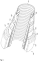
Fig. 1 illustrates a flexible pipe body; and -
Fig. 2 illustrates a riser, flowline and jumper. - In the drawings like reference numerals refer to like parts.
- Throughout this description, reference will be made to a flexible pipe. It will be understood that a flexible pipe is an assembly of a portion of pipe body and one or more end fittings in each of which a respective end of the pipe body is terminated.
Fig. 1 illustrates howpipe body 100 is formed in accordance with an embodiment of the present invention from a combination of layered materials that form a pressure-containing conduit. Although a number of particular layers are illustrated inFig. 1 , it is to be understood that the present invention is broadly applicable to coaxial pipe body structures including two or more layers manufactured from a variety of possible materials. For example, the pipe body may be formed from polymer layers, metallic layers, composite layers, or a combination of different materials. It is to be further noted that the layer thicknesses are shown for illustrative purposes only. - As illustrated in
Fig. 1 , a pipe body includes an optionalinnermost carcass layer 101. The carcass provides an interlocked construction that can be used as the innermost layer to prevent, totally or partially, collapse of aninternal pressure sheath 102 due to pipe decompression, external pressure, and tensile armour pressure and mechanical crushing loads. The carcass layer is often a metallic layer, formed from stainless steel, for example. The carcass layer could also be formed from composite, polymer, or other material, or a combination of materials. It will be appreciated that certain embodiments of the present invention are applicable to 'smooth bore' operations (i.e. without a carcass layer) as well as such 'rough bore' applications (with a carcass layer). - The
internal pressure sheath 102 acts as a fluid retaining layer and comprises a polymer layer that ensures internal fluid integrity. It is to be understood that this layer may itself comprise a number of sub-layers. It will be appreciated that when the optional carcass layer is utilised the internal pressure sheath is often referred to by those skilled in the art as a barrier layer. In operation without such a carcass (so-called smooth bore operation) the internal pressure sheath may be referred to as a liner. - A
pressure armour layer 103 is a structural layer that increases the resistance of the flexible pipe to internal and external pressure and mechanical crushing loads. The layer also structurally supports the internal pressure sheath. In a preferred embodiment, thepressure armour layer 103 is formed from the thermoplastic composite described herein. - The flexible pipe body also includes an optional first
tensile armour layer 105 and optional secondtensile armour layer 106. Each tensile armour layer is used to sustain tensile loads and internal pressure. The tensile armour layer is often formed from a plurality of (e.g. metallic) wires (to impart strength to the layer) that are located over an inner layer and are helically wound along the length of the pipe at a lay angle typically between about 10° to 55°. The tensile armour layers are often counter-wound in pairs. The tensile armour layers are often metallic layers, formed from carbon steel, for example. The tensile armour layers could also be formed from composite, polymer, or other material, or a combination of materials. - The flexible pipe body shown also includes optional layers of
tape 104 which help contain underlying layers and to some extent prevent abrasion between adjacent layers, or indeed as an outer surface of the flexible pipe in areas which may experience abrasion during service. The tape layer may be a polymer or composite or a combination of materials. Thetape layer 104 may be formed of the thermoplastic composite described herein. - The flexible pipe body also typically includes optional layers of insulation 107 and an
outer sheath 108, which comprises a polymer layer used to protect the pipe against penetration of seawater and other external environments, corrosion, abrasion and mechanical damage. - Each flexible pipe comprises at least one portion, sometimes referred to as a segment or section of
pipe body 100 together with an end fitting located at at least one end of the flexible pipe. An end fitting provides a mechanical device which forms the transition between the flexible pipe body and a connector. The different pipe layers as shown, for example, inFig. 1 are terminated in the end fitting in such a way as to transfer the load between the flexible pipe and the connector. -
Fig. 2 illustrates ariser assembly 200 suitable for transporting production fluid such as oil and/or gas and/or water from asub-sea location 201 to a floating facility. For example, inFig. 2 thesub-sea location 201 includes a sub-sea flow line. Theflexible flow line 205 comprises a flexible pipe, wholly or in part, resting on thesea floor 204 or buried below the sea floor and used in a static application. The floating facility may be provided by a platform and/or buoy or, as illustrated inFig. 2 , aship 200. Theriser assembly 200 is provided as a flexible riser, that is to say aflexible pipe 203 connecting the ship to the sea floor installation. The flexible pipe may be in segments of flexible pipe body with connecting end fittings. - It will be appreciated that there are different types of riser, as is well-known by those skilled in the art. Embodiments of the present invention may be used with any type of riser, such as a freely suspended (free, catenary riser), a riser restrained to some extent (buoys, chains), totally restrained riser or enclosed in a tube (I or J tubes).
-
Fig. 2 also illustrates how portions of flexible pipe can be utilised as aflow line 205 orjumper 206. - It will be clear to a person skilled in the art that features described in relation to any of the embodiments described above can be applicable interchangeably between the different embodiments. The embodiments described above are examples to illustrate various features of the invention.
- Throughout the description and claims of this specification, the words "comprise" and "contain" and variations of them mean "including but not limited to", and they are not intended to (and do not) exclude other moieties, additives, components, integers or steps. Throughout the description and claims of this specification, the singular encompasses the plural unless the context otherwise requires. In particular, where the indefinite article is used, the specification is to be understood as contemplating plurality as well as singularity, unless the context requires otherwise.
- Features, integers, characteristics, compounds, chemical moieties or groups described in conjunction with a particular aspect, embodiment or example of the invention are to be understood to be applicable to any other aspect, embodiment or example described herein unless incompatible therewith. All of the features disclosed in this specification (including any accompanying claims, abstract and drawings), and/or all of the steps of any method or process so disclosed, may be combined in any combination, except combinations where at least some of such features and/or steps are mutually exclusive. The invention is not restricted to the details of any foregoing embodiments. The invention extends to any novel one, or any novel combination, of the features disclosed in this specification (including any accompanying claims, abstract and drawings), or to any novel one, or any novel combination, of the steps of any method or process so disclosed.
Claims (16)
- A thermoplastic composite comprising fluoropolymer filaments and carbon fibre filaments, wherein the fluoropolymer filaments and carbon fibre filaments are commingled to form an intimate mixture, and wherein the fluoropolymer has a melt flow index (230∘C/2.16kg) in the range of 50 to 80 g/10min measured using ASTM D1238, ISO 1133; wherein the fluoropolymer preferably has a melt flow index (230°C/2.16kg) in the range of 60 to 70 g/10min.
- A composite as claimed in claim 1, wherein the carbon filaments have a tow size of 3000 to 12000.
- A composite as claimed in any one of claim 1 or 2, wherein the fluoropolymer is selected from at least one of perfluoroalkoxy alkanes (PFA), poly(ethene-co-tetrafluoroethene) (ETFE), polytetrafluoroethylene (PTFE), fluorinated ethylene propylene (FEP) and polyvinylidene fluoride (PVDF), wherein the fluoropolymer is preferably polyvinylidene fluoride (PVDF).
- A composite as claimed in any one of claims 1 to 3, wherein the fluoropolymer is present in an amount of 30 to 70 weight% of the total weight of the fluoropolymer and carbon fibre.
- A composite as claimed in any one of claims 1 to 4, which is in the form of a yarn of the composite, preferably in the form of a tape formed from a plurality of yarns of the composite.
- A composite as claimed in claim 5, wherein the tape comprises a first region formed from a plurality of yarns of the composite having a first concentration of carbon fibre, and a second region formed from a plurality of yarns of the composite having a second concentration of carbon fibre, wherein the first and second concentrations are different.
- A composite as claimed in claim 5 or 6, wherein the tape comprises a region formed from a plurality of yarns of the composite, and a different region formed from a plurality of yarns consisting essentially of the fluoropolymer filaments.
- A flexible pipe comprising at least one pipe layer formed from a tape of a composite as claimed in any one of claims 1 to 7.
- A pipe as claimed in claim 8, wherein the at least one pipe layer formed from a tape of the composite is a pressure armour layer, which is positioned adjacent to a tubular polymer layer, wherein the tubular polymer layer is preferably formed on the inside of the pressure armour layer as a fluid barrier layer.
- A pipe as claimed in any one of claims 8 and 9, wherein the pipe layer is obtainable by wrapping the tape around a pipe body to form a pipe layer, and heating the tape so that the fluoropolymer filaments melt around the carbon filaments to form a fluoropolymer matrix.
- A method of making a thermoplastic composite as claimed in any one of claims 1 to 7, which comprises commingling fluoropolymer filaments and carbon fibre filaments to form an intimate mixture.
- A method as claimed in claim 11, wherein the filaments are commingled using a compressed gas or a series of combs to form the intimate mixture of the filaments.
- A method as claimed in claim 11 or 12, which comprises forming yarns of the commingled filaments, and compressing or extruding the yarns to form a tape of the thermoplastic composite.
- A method as claimed in claim 13, which comprises:arranging a first region of yarns having a first concentration of carbon fibre adjacent to a second region of yarns having a second concentration of carbon fibre, andcompressing or extruding the yarns to form a tape, whereby the tape has a first region having a first concentration of carbon fibre, and a second region having a second concentration of carbon fibre.
- A method as claimed in claim 13, which comprisesarranging a first region of yarns that contain carbon fibre adjacent to a second region of yarns consisting essentially of fluoropolymer, andcompressing or extruding the yarns to form a tape, whereby the tape has a first region containing carbon fibre, and a second region consisting essentially of fluoropolymer.
- A method as claimed in any one of claims 13 to 15, which comprises wrapping the tape around a pipe body, and heating the wrapped tape so that the fluoropolymer filaments melt around the carbon filaments to form a fluoropolymer matrix, wherein the pipe body preferably comprises an extruded tubular polymer layer.
Priority Applications (1)
| Application Number | Priority Date | Filing Date | Title |
|---|---|---|---|
| EP21202990.4A EP3967493A1 (en) | 2016-09-30 | 2017-09-28 | Thermoplastic composite |
Applications Claiming Priority (2)
| Application Number | Priority Date | Filing Date | Title |
|---|---|---|---|
| GBGB1616706.6A GB201616706D0 (en) | 2016-09-30 | 2016-09-30 | Thermoplastic composite |
| PCT/GB2017/052918 WO2018060718A2 (en) | 2016-09-30 | 2017-09-28 | Thermoplastic composite |
Related Child Applications (2)
| Application Number | Title | Priority Date | Filing Date |
|---|---|---|---|
| EP21202990.4A Division-Into EP3967493A1 (en) | 2016-09-30 | 2017-09-28 | Thermoplastic composite |
| EP21202990.4A Division EP3967493A1 (en) | 2016-09-30 | 2017-09-28 | Thermoplastic composite |
Publications (2)
| Publication Number | Publication Date |
|---|---|
| EP3519187A2 EP3519187A2 (en) | 2019-08-07 |
| EP3519187B1 true EP3519187B1 (en) | 2022-02-23 |
Family
ID=57570952
Family Applications (2)
| Application Number | Title | Priority Date | Filing Date |
|---|---|---|---|
| EP21202990.4A Pending EP3967493A1 (en) | 2016-09-30 | 2017-09-28 | Thermoplastic composite |
| EP17780174.3A Active EP3519187B1 (en) | 2016-09-30 | 2017-09-28 | Thermoplastic composite |
Family Applications Before (1)
| Application Number | Title | Priority Date | Filing Date |
|---|---|---|---|
| EP21202990.4A Pending EP3967493A1 (en) | 2016-09-30 | 2017-09-28 | Thermoplastic composite |
Country Status (9)
| Country | Link |
|---|---|
| US (2) | US11529781B2 (en) |
| EP (2) | EP3967493A1 (en) |
| CN (3) | CN109789687A (en) |
| BR (3) | BR122020019421B1 (en) |
| DK (1) | DK3519187T3 (en) |
| ES (1) | ES2910175T3 (en) |
| GB (1) | GB201616706D0 (en) |
| MY (1) | MY193621A (en) |
| WO (1) | WO2018060718A2 (en) |
Families Citing this family (4)
| Publication number | Priority date | Publication date | Assignee | Title |
|---|---|---|---|---|
| GB2564708B (en) * | 2017-07-21 | 2020-02-12 | Magma Global Ltd | Void volume measurement for a composite pipe |
| GB201916362D0 (en) | 2019-11-11 | 2019-12-25 | Ge Oil & Gas Uk Ltd | Splicing method and apparatus |
| WO2021104914A1 (en) * | 2019-11-25 | 2021-06-03 | National Oilwell Varco Denmark I/S | An unbonded flexible pipe |
| US12331613B2 (en) | 2023-10-24 | 2025-06-17 | Halliburton Energy Services, Inc. | Composite downhole tools |
Family Cites Families (26)
| Publication number | Priority date | Publication date | Assignee | Title |
|---|---|---|---|---|
| JPS56160481A (en) * | 1980-05-16 | 1981-12-10 | Kureha Chemical Ind Co Ltd | Carbon fiber reinforced pipe made of polypropylene |
| US5069959A (en) * | 1988-06-20 | 1991-12-03 | E. I. Du Pont De Nemours And Company | Structural composites of fluoropolymers reinforced with continuous filament fibers |
| US4975321A (en) * | 1988-06-20 | 1990-12-04 | E. I. Du Pont De Nemours And Company | Structural composites of fluoropolymers reinforced with continuous filament fibers |
| JP3771360B2 (en) * | 1997-10-24 | 2006-04-26 | 新日本石油株式会社 | Tubular body made of fiber reinforced composite material |
| JPH11204114A (en) | 1998-01-20 | 1999-07-30 | Daikin Ind Ltd | Electrode material |
| US6132866A (en) | 1998-01-28 | 2000-10-17 | E. I. Du Pont De Nemours And Company | Yarn blend for friction applications |
| US20020079610A1 (en) * | 1998-11-24 | 2002-06-27 | Uy William Cheng | High melt spinning of fluoropolymer fibers |
| US6667097B2 (en) * | 1999-01-29 | 2003-12-23 | Edward William Tokarsky | High speed melt spinning of fluoropolymer fibers |
| US20040194444A1 (en) * | 2003-04-04 | 2004-10-07 | Vinod Yashavant Vinayak | Fluoropolymer yarn blends |
| JP2005220486A (en) | 2004-02-06 | 2005-08-18 | Toray Ind Inc | Fluorofiber interwoven fabrics and composite materials |
| US9334587B2 (en) * | 2005-02-11 | 2016-05-10 | W. L. Gore & Associates, Inc. | Fluoropolymer fiber composite bundle |
| JP2007031844A (en) | 2005-07-22 | 2007-02-08 | Toray Ind Inc | Photocatalyst carrying fabric |
| US8057887B2 (en) * | 2005-08-17 | 2011-11-15 | Rampart Fibers, LLC | Composite materials including high modulus polyolefin fibers |
| US20070048476A1 (en) * | 2005-08-31 | 2007-03-01 | Freudenberg-Nok General Partnership | Assemblies sealed with multilayer composite compression seals having a layer of dispersed fluoroelastomer in thermoplastic |
| US8048351B2 (en) * | 2006-08-14 | 2011-11-01 | Swagelok Company | Bio-pharmaceutical hose |
| GB201105067D0 (en) * | 2011-03-25 | 2011-05-11 | Wellstream Int Ltd | Flexible pipe body and method of producing same |
| GB201121876D0 (en) * | 2011-12-20 | 2012-02-01 | Wellstream Int Ltd | Flexible pipe body and method of producing same |
| FR2987883B1 (en) | 2012-03-06 | 2014-05-02 | Technip France | ARMOR ELEMENT FOR A FLEXIBLE LINE INTENDED TO BE PLACED IN A WATER EXTEND, FLEXIBLE LINE, METHOD AND METHOD THEREOF |
| WO2014078680A1 (en) | 2012-11-16 | 2014-05-22 | Kongsberg Actuation Systems Ii, Inc. | Method of forming a hose assembly |
| CN103075580B (en) * | 2013-01-22 | 2014-12-10 | 江苏奇一科技有限公司 | Continuous fiber reinforced thermoplastic composite high-pressure pipeline |
| GB201306665D0 (en) * | 2013-04-12 | 2013-05-29 | Wellstream Int Ltd | Elongate tape element and method |
| GB201306667D0 (en) * | 2013-04-12 | 2013-05-29 | Wellstream Int Ltd | A flexible pipe body and method of manufacture |
| JP6166577B2 (en) | 2013-04-16 | 2017-07-19 | 三井・デュポンフロロケミカル株式会社 | Fluororesin composition and molded product thereof |
| US20150011697A1 (en) * | 2013-07-03 | 2015-01-08 | E I Du Pont De Nemours And Company | Melt-processible vinyl fluoride interpolymers of low crystallinity |
| GB201402264D0 (en) * | 2014-02-10 | 2014-03-26 | Wellstream Int Ltd | Composite |
| GB2523204B (en) * | 2014-02-18 | 2018-02-07 | Sigma Prec Components Uk Limited | Fibre reinforced thermoplastic composite rigid pipe |
-
2016
- 2016-09-30 GB GBGB1616706.6A patent/GB201616706D0/en not_active Ceased
-
2017
- 2017-09-28 CN CN201780060852.1A patent/CN109789687A/en active Pending
- 2017-09-28 US US16/338,236 patent/US11529781B2/en active Active
- 2017-09-28 EP EP21202990.4A patent/EP3967493A1/en active Pending
- 2017-09-28 CN CN202410485775.6A patent/CN118361601A/en active Pending
- 2017-09-28 MY MYPI2019001642A patent/MY193621A/en unknown
- 2017-09-28 BR BR122020019421-9A patent/BR122020019421B1/en active IP Right Grant
- 2017-09-28 EP EP17780174.3A patent/EP3519187B1/en active Active
- 2017-09-28 DK DK17780174.3T patent/DK3519187T3/en active
- 2017-09-28 BR BR122020019417-0A patent/BR122020019417B1/en active IP Right Grant
- 2017-09-28 CN CN202410485846.2A patent/CN118361602A/en active Pending
- 2017-09-28 WO PCT/GB2017/052918 patent/WO2018060718A2/en not_active Ceased
- 2017-09-28 ES ES17780174T patent/ES2910175T3/en active Active
- 2017-09-28 BR BR112019006372-2A patent/BR112019006372B1/en active IP Right Grant
-
2022
- 2022-10-18 US US17/968,013 patent/US11958259B2/en active Active
Non-Patent Citations (1)
| Title |
|---|
| None * |
Also Published As
| Publication number | Publication date |
|---|---|
| WO2018060718A3 (en) | 2018-05-03 |
| BR122020019421B1 (en) | 2023-01-24 |
| BR122020019417B1 (en) | 2023-01-24 |
| DK3519187T3 (en) | 2022-04-04 |
| CN109789687A (en) | 2019-05-21 |
| MY193621A (en) | 2022-10-20 |
| ES2910175T3 (en) | 2022-05-11 |
| EP3967493A1 (en) | 2022-03-16 |
| BR112019006372B1 (en) | 2022-11-29 |
| CN118361601A (en) | 2024-07-19 |
| US20200031071A1 (en) | 2020-01-30 |
| EP3519187A2 (en) | 2019-08-07 |
| CN118361602A (en) | 2024-07-19 |
| US20230030995A1 (en) | 2023-02-02 |
| WO2018060718A2 (en) | 2018-04-05 |
| US11958259B2 (en) | 2024-04-16 |
| BR112019006372A2 (en) | 2019-08-20 |
| GB201616706D0 (en) | 2016-11-16 |
| US11529781B2 (en) | 2022-12-20 |
Similar Documents
| Publication | Publication Date | Title |
|---|---|---|
| US11958259B2 (en) | Thermoplastic composite | |
| EP3744499B1 (en) | Nonmetallic flexible pipe and manufacturing method thereof | |
| US9090019B2 (en) | Flexible pipe | |
| US11047512B2 (en) | Flexible pipe with layers of metal armour and layers of composite armour | |
| US10221971B2 (en) | Flexible pipe body and method of manufacture | |
| EP2724853B1 (en) | Flexible pipe body layer and method of producing same | |
| US11345111B2 (en) | Composite | |
| WO2018046886A1 (en) | Flexible pipe design and manufacture | |
| US9951893B2 (en) | Flexible pipe body and method of producing same |
Legal Events
| Date | Code | Title | Description |
|---|---|---|---|
| STAA | Information on the status of an ep patent application or granted ep patent |
Free format text: STATUS: UNKNOWN |
|
| STAA | Information on the status of an ep patent application or granted ep patent |
Free format text: STATUS: THE INTERNATIONAL PUBLICATION HAS BEEN MADE |
|
| PUAI | Public reference made under article 153(3) epc to a published international application that has entered the european phase |
Free format text: ORIGINAL CODE: 0009012 |
|
| STAA | Information on the status of an ep patent application or granted ep patent |
Free format text: STATUS: REQUEST FOR EXAMINATION WAS MADE |
|
| 17P | Request for examination filed |
Effective date: 20190327 |
|
| AK | Designated contracting states |
Kind code of ref document: A2 Designated state(s): AL AT BE BG CH CY CZ DE DK EE ES FI FR GB GR HR HU IE IS IT LI LT LU LV MC MK MT NL NO PL PT RO RS SE SI SK SM TR |
|
| AX | Request for extension of the european patent |
Extension state: BA ME |
|
| DAV | Request for validation of the european patent (deleted) | ||
| DAX | Request for extension of the european patent (deleted) | ||
| STAA | Information on the status of an ep patent application or granted ep patent |
Free format text: STATUS: EXAMINATION IS IN PROGRESS |
|
| 17Q | First examination report despatched |
Effective date: 20200319 |
|
| RAP1 | Party data changed (applicant data changed or rights of an application transferred) |
Owner name: BAKER HUGHES ENERGY TECHNOLOGY UK LIMITED |
|
| GRAP | Despatch of communication of intention to grant a patent |
Free format text: ORIGINAL CODE: EPIDOSNIGR1 |
|
| STAA | Information on the status of an ep patent application or granted ep patent |
Free format text: STATUS: GRANT OF PATENT IS INTENDED |
|
| INTG | Intention to grant announced |
Effective date: 20210720 |
|
| GRAS | Grant fee paid |
Free format text: ORIGINAL CODE: EPIDOSNIGR3 |
|
| RIN1 | Information on inventor provided before grant (corrected) |
Inventor name: FINCH, DAVID Inventor name: LATTO, JAMES Inventor name: JHA, VINEET Inventor name: DODDS, NEVILLE Inventor name: AL-ZUBAIDY, MAJEED |
|
| GRAA | (expected) grant |
Free format text: ORIGINAL CODE: 0009210 |
|
| STAA | Information on the status of an ep patent application or granted ep patent |
Free format text: STATUS: THE PATENT HAS BEEN GRANTED |
|
| AK | Designated contracting states |
Kind code of ref document: B1 Designated state(s): AL AT BE BG CH CY CZ DE DK EE ES FI FR GB GR HR HU IE IS IT LI LT LU LV MC MK MT NL NO PL PT RO RS SE SI SK SM TR |
|
| REG | Reference to a national code |
Ref country code: GB Ref legal event code: FG4D |
|
| REG | Reference to a national code |
Ref country code: CH Ref legal event code: EP |
|
| REG | Reference to a national code |
Ref country code: DE Ref legal event code: R096 Ref document number: 602017053738 Country of ref document: DE |
|
| REG | Reference to a national code |
Ref country code: AT Ref legal event code: REF Ref document number: 1470142 Country of ref document: AT Kind code of ref document: T Effective date: 20220315 |
|
| REG | Reference to a national code |
Ref country code: IE Ref legal event code: FG4D |
|
| REG | Reference to a national code |
Ref country code: DK Ref legal event code: T3 Effective date: 20220331 |
|
| REG | Reference to a national code |
Ref country code: NL Ref legal event code: FP |
|
| REG | Reference to a national code |
Ref country code: ES Ref legal event code: FG2A Ref document number: 2910175 Country of ref document: ES Kind code of ref document: T3 Effective date: 20220511 |
|
| REG | Reference to a national code |
Ref country code: LT Ref legal event code: MG9D |
|
| REG | Reference to a national code |
Ref country code: AT Ref legal event code: MK05 Ref document number: 1470142 Country of ref document: AT Kind code of ref document: T Effective date: 20220223 |
|
| PG25 | Lapsed in a contracting state [announced via postgrant information from national office to epo] |
Ref country code: SE Free format text: LAPSE BECAUSE OF FAILURE TO SUBMIT A TRANSLATION OF THE DESCRIPTION OR TO PAY THE FEE WITHIN THE PRESCRIBED TIME-LIMIT Effective date: 20220223 Ref country code: RS Free format text: LAPSE BECAUSE OF FAILURE TO SUBMIT A TRANSLATION OF THE DESCRIPTION OR TO PAY THE FEE WITHIN THE PRESCRIBED TIME-LIMIT Effective date: 20220223 Ref country code: PT Free format text: LAPSE BECAUSE OF FAILURE TO SUBMIT A TRANSLATION OF THE DESCRIPTION OR TO PAY THE FEE WITHIN THE PRESCRIBED TIME-LIMIT Effective date: 20220623 Ref country code: NO Free format text: LAPSE BECAUSE OF FAILURE TO SUBMIT A TRANSLATION OF THE DESCRIPTION OR TO PAY THE FEE WITHIN THE PRESCRIBED TIME-LIMIT Effective date: 20220523 Ref country code: LT Free format text: LAPSE BECAUSE OF FAILURE TO SUBMIT A TRANSLATION OF THE DESCRIPTION OR TO PAY THE FEE WITHIN THE PRESCRIBED TIME-LIMIT Effective date: 20220223 Ref country code: HR Free format text: LAPSE BECAUSE OF FAILURE TO SUBMIT A TRANSLATION OF THE DESCRIPTION OR TO PAY THE FEE WITHIN THE PRESCRIBED TIME-LIMIT Effective date: 20220223 Ref country code: BG Free format text: LAPSE BECAUSE OF FAILURE TO SUBMIT A TRANSLATION OF THE DESCRIPTION OR TO PAY THE FEE WITHIN THE PRESCRIBED TIME-LIMIT Effective date: 20220523 |
|
| PG25 | Lapsed in a contracting state [announced via postgrant information from national office to epo] |
Ref country code: PL Free format text: LAPSE BECAUSE OF FAILURE TO SUBMIT A TRANSLATION OF THE DESCRIPTION OR TO PAY THE FEE WITHIN THE PRESCRIBED TIME-LIMIT Effective date: 20220223 Ref country code: LV Free format text: LAPSE BECAUSE OF FAILURE TO SUBMIT A TRANSLATION OF THE DESCRIPTION OR TO PAY THE FEE WITHIN THE PRESCRIBED TIME-LIMIT Effective date: 20220223 Ref country code: GR Free format text: LAPSE BECAUSE OF FAILURE TO SUBMIT A TRANSLATION OF THE DESCRIPTION OR TO PAY THE FEE WITHIN THE PRESCRIBED TIME-LIMIT Effective date: 20220524 Ref country code: FI Free format text: LAPSE BECAUSE OF FAILURE TO SUBMIT A TRANSLATION OF THE DESCRIPTION OR TO PAY THE FEE WITHIN THE PRESCRIBED TIME-LIMIT Effective date: 20220223 Ref country code: AT Free format text: LAPSE BECAUSE OF FAILURE TO SUBMIT A TRANSLATION OF THE DESCRIPTION OR TO PAY THE FEE WITHIN THE PRESCRIBED TIME-LIMIT Effective date: 20220223 |
|
| PG25 | Lapsed in a contracting state [announced via postgrant information from national office to epo] |
Ref country code: IS Free format text: LAPSE BECAUSE OF FAILURE TO SUBMIT A TRANSLATION OF THE DESCRIPTION OR TO PAY THE FEE WITHIN THE PRESCRIBED TIME-LIMIT Effective date: 20220623 |
|
| PG25 | Lapsed in a contracting state [announced via postgrant information from national office to epo] |
Ref country code: SM Free format text: LAPSE BECAUSE OF FAILURE TO SUBMIT A TRANSLATION OF THE DESCRIPTION OR TO PAY THE FEE WITHIN THE PRESCRIBED TIME-LIMIT Effective date: 20220223 Ref country code: SK Free format text: LAPSE BECAUSE OF FAILURE TO SUBMIT A TRANSLATION OF THE DESCRIPTION OR TO PAY THE FEE WITHIN THE PRESCRIBED TIME-LIMIT Effective date: 20220223 Ref country code: RO Free format text: LAPSE BECAUSE OF FAILURE TO SUBMIT A TRANSLATION OF THE DESCRIPTION OR TO PAY THE FEE WITHIN THE PRESCRIBED TIME-LIMIT Effective date: 20220223 Ref country code: EE Free format text: LAPSE BECAUSE OF FAILURE TO SUBMIT A TRANSLATION OF THE DESCRIPTION OR TO PAY THE FEE WITHIN THE PRESCRIBED TIME-LIMIT Effective date: 20220223 Ref country code: CZ Free format text: LAPSE BECAUSE OF FAILURE TO SUBMIT A TRANSLATION OF THE DESCRIPTION OR TO PAY THE FEE WITHIN THE PRESCRIBED TIME-LIMIT Effective date: 20220223 |
|
| REG | Reference to a national code |
Ref country code: DE Ref legal event code: R097 Ref document number: 602017053738 Country of ref document: DE |
|
| PG25 | Lapsed in a contracting state [announced via postgrant information from national office to epo] |
Ref country code: AL Free format text: LAPSE BECAUSE OF FAILURE TO SUBMIT A TRANSLATION OF THE DESCRIPTION OR TO PAY THE FEE WITHIN THE PRESCRIBED TIME-LIMIT Effective date: 20220223 |
|
| PLBE | No opposition filed within time limit |
Free format text: ORIGINAL CODE: 0009261 |
|
| STAA | Information on the status of an ep patent application or granted ep patent |
Free format text: STATUS: NO OPPOSITION FILED WITHIN TIME LIMIT |
|
| PGFP | Annual fee paid to national office [announced via postgrant information from national office to epo] |
Ref country code: ES Payment date: 20221003 Year of fee payment: 6 |
|
| 26N | No opposition filed |
Effective date: 20221124 |
|
| PG25 | Lapsed in a contracting state [announced via postgrant information from national office to epo] |
Ref country code: SI Free format text: LAPSE BECAUSE OF FAILURE TO SUBMIT A TRANSLATION OF THE DESCRIPTION OR TO PAY THE FEE WITHIN THE PRESCRIBED TIME-LIMIT Effective date: 20220223 |
|
| PG25 | Lapsed in a contracting state [announced via postgrant information from national office to epo] |
Ref country code: MC Free format text: LAPSE BECAUSE OF FAILURE TO SUBMIT A TRANSLATION OF THE DESCRIPTION OR TO PAY THE FEE WITHIN THE PRESCRIBED TIME-LIMIT Effective date: 20220223 |
|
| REG | Reference to a national code |
Ref country code: CH Ref legal event code: PL |
|
| REG | Reference to a national code |
Ref country code: BE Ref legal event code: MM Effective date: 20220930 |
|
| PG25 | Lapsed in a contracting state [announced via postgrant information from national office to epo] |
Ref country code: LU Free format text: LAPSE BECAUSE OF NON-PAYMENT OF DUE FEES Effective date: 20220928 |
|
| P01 | Opt-out of the competence of the unified patent court (upc) registered |
Effective date: 20230526 |
|
| PG25 | Lapsed in a contracting state [announced via postgrant information from national office to epo] |
Ref country code: LI Free format text: LAPSE BECAUSE OF NON-PAYMENT OF DUE FEES Effective date: 20220930 Ref country code: IT Free format text: LAPSE BECAUSE OF FAILURE TO SUBMIT A TRANSLATION OF THE DESCRIPTION OR TO PAY THE FEE WITHIN THE PRESCRIBED TIME-LIMIT Effective date: 20220223 Ref country code: IE Free format text: LAPSE BECAUSE OF NON-PAYMENT OF DUE FEES Effective date: 20220928 Ref country code: CH Free format text: LAPSE BECAUSE OF NON-PAYMENT OF DUE FEES Effective date: 20220930 |
|
| PG25 | Lapsed in a contracting state [announced via postgrant information from national office to epo] |
Ref country code: BE Free format text: LAPSE BECAUSE OF NON-PAYMENT OF DUE FEES Effective date: 20220930 |
|
| PG25 | Lapsed in a contracting state [announced via postgrant information from national office to epo] |
Ref country code: HU Free format text: LAPSE BECAUSE OF FAILURE TO SUBMIT A TRANSLATION OF THE DESCRIPTION OR TO PAY THE FEE WITHIN THE PRESCRIBED TIME-LIMIT; INVALID AB INITIO Effective date: 20170928 |
|
| PG25 | Lapsed in a contracting state [announced via postgrant information from national office to epo] |
Ref country code: CY Free format text: LAPSE BECAUSE OF FAILURE TO SUBMIT A TRANSLATION OF THE DESCRIPTION OR TO PAY THE FEE WITHIN THE PRESCRIBED TIME-LIMIT Effective date: 20220223 |
|
| PG25 | Lapsed in a contracting state [announced via postgrant information from national office to epo] |
Ref country code: MK Free format text: LAPSE BECAUSE OF FAILURE TO SUBMIT A TRANSLATION OF THE DESCRIPTION OR TO PAY THE FEE WITHIN THE PRESCRIBED TIME-LIMIT Effective date: 20220223 |
|
| PG25 | Lapsed in a contracting state [announced via postgrant information from national office to epo] |
Ref country code: TR Free format text: LAPSE BECAUSE OF FAILURE TO SUBMIT A TRANSLATION OF THE DESCRIPTION OR TO PAY THE FEE WITHIN THE PRESCRIBED TIME-LIMIT Effective date: 20220223 |
|
| PG25 | Lapsed in a contracting state [announced via postgrant information from national office to epo] |
Ref country code: MT Free format text: LAPSE BECAUSE OF FAILURE TO SUBMIT A TRANSLATION OF THE DESCRIPTION OR TO PAY THE FEE WITHIN THE PRESCRIBED TIME-LIMIT Effective date: 20220223 |
|
| REG | Reference to a national code |
Ref country code: ES Ref legal event code: FD2A Effective date: 20241031 |
|
| PG25 | Lapsed in a contracting state [announced via postgrant information from national office to epo] |
Ref country code: ES Free format text: LAPSE BECAUSE OF NON-PAYMENT OF DUE FEES Effective date: 20230929 |
|
| PG25 | Lapsed in a contracting state [announced via postgrant information from national office to epo] |
Ref country code: ES Free format text: LAPSE BECAUSE OF NON-PAYMENT OF DUE FEES Effective date: 20230929 |
|
| PGFP | Annual fee paid to national office [announced via postgrant information from national office to epo] |
Ref country code: NL Payment date: 20250820 Year of fee payment: 9 |
|
| PGFP | Annual fee paid to national office [announced via postgrant information from national office to epo] |
Ref country code: DK Payment date: 20250820 Year of fee payment: 9 Ref country code: DE Payment date: 20250820 Year of fee payment: 9 |
|
| PGFP | Annual fee paid to national office [announced via postgrant information from national office to epo] |
Ref country code: GB Payment date: 20250820 Year of fee payment: 9 |
|
| PGFP | Annual fee paid to national office [announced via postgrant information from national office to epo] |
Ref country code: FR Payment date: 20250820 Year of fee payment: 9 |