EP3518774B1 - Vorrichtungen zur intraluminalen bildgebung mit einer reduzierten anzahl von signalkanälen - Google Patents
Vorrichtungen zur intraluminalen bildgebung mit einer reduzierten anzahl von signalkanälen Download PDFInfo
- Publication number
- EP3518774B1 EP3518774B1 EP17777002.1A EP17777002A EP3518774B1 EP 3518774 B1 EP3518774 B1 EP 3518774B1 EP 17777002 A EP17777002 A EP 17777002A EP 3518774 B1 EP3518774 B1 EP 3518774B1
- Authority
- EP
- European Patent Office
- Prior art keywords
- imaging
- micro
- assembly
- former
- cable
- Prior art date
- Legal status (The legal status is an assumption and is not a legal conclusion. Google has not performed a legal analysis and makes no representation as to the accuracy of the status listed.)
- Active
Links
- 238000003384 imaging method Methods 0.000 title claims description 226
- 238000002604 ultrasonography Methods 0.000 claims description 30
- 238000000034 method Methods 0.000 description 28
- 238000012545 processing Methods 0.000 description 22
- 230000001934 delay Effects 0.000 description 11
- 238000010586 diagram Methods 0.000 description 10
- 238000012285 ultrasound imaging Methods 0.000 description 9
- 230000008901 benefit Effects 0.000 description 5
- 238000004519 manufacturing process Methods 0.000 description 5
- 239000000463 material Substances 0.000 description 5
- 238000002592 echocardiography Methods 0.000 description 4
- 230000007246 mechanism Effects 0.000 description 4
- 230000008569 process Effects 0.000 description 4
- 238000002679 ablation Methods 0.000 description 3
- 210000004351 coronary vessel Anatomy 0.000 description 3
- 206010003658 Atrial Fibrillation Diseases 0.000 description 2
- 210000003484 anatomy Anatomy 0.000 description 2
- 239000003990 capacitor Substances 0.000 description 2
- 230000001010 compromised effect Effects 0.000 description 2
- 230000003247 decreasing effect Effects 0.000 description 2
- 230000003111 delayed effect Effects 0.000 description 2
- 238000005516 engineering process Methods 0.000 description 2
- 238000003780 insertion Methods 0.000 description 2
- 230000037431 insertion Effects 0.000 description 2
- 210000005248 left atrial appendage Anatomy 0.000 description 2
- 230000004048 modification Effects 0.000 description 2
- 238000012986 modification Methods 0.000 description 2
- 230000008439 repair process Effects 0.000 description 2
- 238000012546 transfer Methods 0.000 description 2
- QZHBYNSSDLTCRG-LREBCSMRSA-N 5-bromo-n-(4,5-dihydro-1h-imidazol-2-yl)quinoxalin-6-amine;(2r,3r)-2,3-dihydroxybutanedioic acid Chemical compound OC(=O)[C@H](O)[C@@H](O)C(O)=O.C1=CC2=NC=CN=C2C(Br)=C1NC1=NCCN1 QZHBYNSSDLTCRG-LREBCSMRSA-N 0.000 description 1
- 230000003213 activating effect Effects 0.000 description 1
- 230000004913 activation Effects 0.000 description 1
- 239000000853 adhesive Substances 0.000 description 1
- 230000001070 adhesive effect Effects 0.000 description 1
- 230000004075 alteration Effects 0.000 description 1
- 230000033228 biological regulation Effects 0.000 description 1
- 210000004204 blood vessel Anatomy 0.000 description 1
- 210000000748 cardiovascular system Anatomy 0.000 description 1
- 230000008859 change Effects 0.000 description 1
- 238000005520 cutting process Methods 0.000 description 1
- 230000007423 decrease Effects 0.000 description 1
- 238000011161 development Methods 0.000 description 1
- 238000012377 drug delivery Methods 0.000 description 1
- 239000002961 echo contrast media Substances 0.000 description 1
- 230000000694 effects Effects 0.000 description 1
- 238000004146 energy storage Methods 0.000 description 1
- 210000003191 femoral vein Anatomy 0.000 description 1
- 230000006870 function Effects 0.000 description 1
- 210000004731 jugular vein Anatomy 0.000 description 1
- 239000004973 liquid crystal related substance Substances 0.000 description 1
- 230000013011 mating Effects 0.000 description 1
- 230000001737 promoting effect Effects 0.000 description 1
- 230000009467 reduction Effects 0.000 description 1
- 239000000523 sample Substances 0.000 description 1
- 238000006467 substitution reaction Methods 0.000 description 1
- 230000001225 therapeutic effect Effects 0.000 description 1
- 238000002560 therapeutic procedure Methods 0.000 description 1
- 230000002792 vascular Effects 0.000 description 1
Images


Classifications
-
- A—HUMAN NECESSITIES
- A61—MEDICAL OR VETERINARY SCIENCE; HYGIENE
- A61B—DIAGNOSIS; SURGERY; IDENTIFICATION
- A61B8/00—Diagnosis using ultrasonic, sonic or infrasonic waves
- A61B8/44—Constructional features of the ultrasonic, sonic or infrasonic diagnostic device
- A61B8/4444—Constructional features of the ultrasonic, sonic or infrasonic diagnostic device related to the probe
- A61B8/4461—Features of the scanning mechanism, e.g. for moving the transducer within the housing of the probe
-
- A—HUMAN NECESSITIES
- A61—MEDICAL OR VETERINARY SCIENCE; HYGIENE
- A61B—DIAGNOSIS; SURGERY; IDENTIFICATION
- A61B8/00—Diagnosis using ultrasonic, sonic or infrasonic waves
- A61B8/08—Detecting organic movements or changes, e.g. tumours, cysts, swellings
- A61B8/0883—Detecting organic movements or changes, e.g. tumours, cysts, swellings for diagnosis of the heart
-
- A—HUMAN NECESSITIES
- A61—MEDICAL OR VETERINARY SCIENCE; HYGIENE
- A61B—DIAGNOSIS; SURGERY; IDENTIFICATION
- A61B8/00—Diagnosis using ultrasonic, sonic or infrasonic waves
- A61B8/12—Diagnosis using ultrasonic, sonic or infrasonic waves in body cavities or body tracts, e.g. by using catheters
-
- A—HUMAN NECESSITIES
- A61—MEDICAL OR VETERINARY SCIENCE; HYGIENE
- A61B—DIAGNOSIS; SURGERY; IDENTIFICATION
- A61B8/00—Diagnosis using ultrasonic, sonic or infrasonic waves
- A61B8/44—Constructional features of the ultrasonic, sonic or infrasonic diagnostic device
- A61B8/4444—Constructional features of the ultrasonic, sonic or infrasonic diagnostic device related to the probe
- A61B8/445—Details of catheter construction
-
- A—HUMAN NECESSITIES
- A61—MEDICAL OR VETERINARY SCIENCE; HYGIENE
- A61B—DIAGNOSIS; SURGERY; IDENTIFICATION
- A61B8/00—Diagnosis using ultrasonic, sonic or infrasonic waves
- A61B8/44—Constructional features of the ultrasonic, sonic or infrasonic diagnostic device
- A61B8/4483—Constructional features of the ultrasonic, sonic or infrasonic diagnostic device characterised by features of the ultrasound transducer
- A61B8/4488—Constructional features of the ultrasonic, sonic or infrasonic diagnostic device characterised by features of the ultrasound transducer the transducer being a phased array
-
- A—HUMAN NECESSITIES
- A61—MEDICAL OR VETERINARY SCIENCE; HYGIENE
- A61B—DIAGNOSIS; SURGERY; IDENTIFICATION
- A61B8/00—Diagnosis using ultrasonic, sonic or infrasonic waves
- A61B8/46—Ultrasonic, sonic or infrasonic diagnostic devices with special arrangements for interfacing with the operator or the patient
- A61B8/461—Displaying means of special interest
- A61B8/466—Displaying means of special interest adapted to display 3D data
-
- A—HUMAN NECESSITIES
- A61—MEDICAL OR VETERINARY SCIENCE; HYGIENE
- A61B—DIAGNOSIS; SURGERY; IDENTIFICATION
- A61B8/00—Diagnosis using ultrasonic, sonic or infrasonic waves
- A61B8/56—Details of data transmission or power supply
-
- G—PHYSICS
- G01—MEASURING; TESTING
- G01S—RADIO DIRECTION-FINDING; RADIO NAVIGATION; DETERMINING DISTANCE OR VELOCITY BY USE OF RADIO WAVES; LOCATING OR PRESENCE-DETECTING BY USE OF THE REFLECTION OR RERADIATION OF RADIO WAVES; ANALOGOUS ARRANGEMENTS USING OTHER WAVES
- G01S15/00—Systems using the reflection or reradiation of acoustic waves, e.g. sonar systems
- G01S15/88—Sonar systems specially adapted for specific applications
- G01S15/89—Sonar systems specially adapted for specific applications for mapping or imaging
- G01S15/8906—Short-range imaging systems; Acoustic microscope systems using pulse-echo techniques
- G01S15/8909—Short-range imaging systems; Acoustic microscope systems using pulse-echo techniques using a static transducer configuration
- G01S15/8915—Short-range imaging systems; Acoustic microscope systems using pulse-echo techniques using a static transducer configuration using a transducer array
- G01S15/8925—Short-range imaging systems; Acoustic microscope systems using pulse-echo techniques using a static transducer configuration using a transducer array the array being a two-dimensional transducer configuration, i.e. matrix or orthogonal linear arrays
-
- G—PHYSICS
- G01—MEASURING; TESTING
- G01S—RADIO DIRECTION-FINDING; RADIO NAVIGATION; DETERMINING DISTANCE OR VELOCITY BY USE OF RADIO WAVES; LOCATING OR PRESENCE-DETECTING BY USE OF THE REFLECTION OR RERADIATION OF RADIO WAVES; ANALOGOUS ARRANGEMENTS USING OTHER WAVES
- G01S15/00—Systems using the reflection or reradiation of acoustic waves, e.g. sonar systems
- G01S15/88—Sonar systems specially adapted for specific applications
- G01S15/89—Sonar systems specially adapted for specific applications for mapping or imaging
- G01S15/8906—Short-range imaging systems; Acoustic microscope systems using pulse-echo techniques
- G01S15/8909—Short-range imaging systems; Acoustic microscope systems using pulse-echo techniques using a static transducer configuration
- G01S15/8915—Short-range imaging systems; Acoustic microscope systems using pulse-echo techniques using a static transducer configuration using a transducer array
- G01S15/8927—Short-range imaging systems; Acoustic microscope systems using pulse-echo techniques using a static transducer configuration using a transducer array using simultaneously or sequentially two or more subarrays or subapertures
Definitions
- the present disclosure relates generally to intraluminal imaging devices and, in particular, to array-based intraluminal imaging devices with a reduced number of signal lines.
- Diagnostic and therapeutic ultrasound catheters have been designed for use inside many areas of the human body.
- a common diagnostic ultrasound methods is intraluminal ultrasound imaging with intra-cardiac echocardiography (ICE) being a specific example of intraluminal imaging.
- ICE intra-cardiac echocardiography
- a single rotating transducer or an array of transducer elements is used to transmit ultrasound at the tips of the catheters.
- the same transducers are used to receive echoes from the tissue.
- a signal generated from the echoes is transferred to a console which allows for the processing, storing, display, or manipulation of the ultrasound-related data.
- Intraluminal imaging catheters such as ICE catheters are usually used to image heart and surrounding structures, for example, to guide and facilitate medical procedures, such as transseptal lumen punctures, left atrial appendage closures, atrial fibrillation ablation, and valve repairs.
- ICE catheters have distal ends which can be articulated by a steering mechanism located in a handle at the proximal end of the catheter.
- an intraluminal imaging catheter such as an ICE catheter may be inserted through the femoral or jugular vein when accessing the anatomy, and steered in the heart to acquire images necessary to the safety of the medical procedures.
- An ICE catheter typically includes imaging transducers for ultrasound imaging that generates and receives acoustic energy.
- the imaging core may include a lined array of transducer elements or transducer elements arranged in any suitable configuration.
- the imaging core is encased in an imaging assembly located at a furthest distal tip of the catheter.
- the imaging assembly is covered with acoustic adhesive materials.
- An electrical cable is soldered to the imaging core and extends through the core of the body of the catheter.
- the electrical cable may carry control core signals and echo signals to facilitate imaging of the heart anatomy.
- the assembly may provide rotational, 2-way, or 4-way steering mechanisms such that anterior, posterior, left, and/or right views of the heart anatomy may be imaged.
- ICE imaging transducers are well known (e.g. Siemens Acunav, St. Jude ViewFlex). These transducers are introduced to the interior of the heart via a blood vessel by means of a catheter. ICE transducers may use a phased array sensor comprising many small individual transducers, each with a separate wire connecting the catheter to the imaging console. Up to 128 wires may be needed, leading to high cost, difficult manufacturing, and compromised image quality.
- phased array ICE transducers large number of wires can be brought up the catheter from the ICE transducer to the imaging system.
- a typical ICE transducer might have 128 transducers and 128 wires individually coupled to the transducers. These wires can all fit inside a catheter with a typical outer diameter of about 3mm. The requirement to have so many wires in such a small diameter effectively precludes the use of coaxial cables for the wires as used in larger ultrasound imaging transducers. Without coaxial cables there is more crosstalk between signal channels and more interference from external noise sources, both of which will degrade the ultrasound image. Additionally, the wires can be individually connected to the elements of the transducer in a compact configuration to fit within the catheter tip. This difficult interconnect operation raises the cost of the transducer and is prone to errors and damage. Once assembled, the fine wires are prone to breaking due to flexure in normal use, decreasing the overall reliability of the transducer.
- ICE transducers create only 2D images while clinicians would like to have the possibility of 3D images.
- 3D ICE transducer currently available has only a small field of view and compromised image quality.
- Micro-beam-forming is a technology that is used in larger ultrasound imaging transducers (e.g. Philips xMatrix, Clearvue, and Lumify transducer lines) both to create 3D images and to reduce the number of wires required.
- WO 2015/150385 discloses an integrated circuit (IC) die a major surface delimited by at least one edge, said major surface carrying a plurality of electrically conductive contact plates extending from the major surface beyond the at least one edge such that each contact plate includes an exposed contact surface portion delimited by the at least one edge for mating with an electrically conductive further contact surface portion on at least one further edge of a body, said at least one further edge delimiting a cavity for receiving the IC die.
- An ultrasound probe including such an IC die is also disclosed.
- US6468216 discloses an ultrasonic imaging method and apparatus for imaging the coronary arteries of the heart.
- the vascular system is infused with an ultrasonic contrast agent.
- a volumetric region of the heart wall including a coronary artery is three dimensionally scanned.
- a projection image of the volumetric region is produced from the scanning, providing a two dimensional contrast image of the coronary artery with the appearance of an angiogram.
- US 2016/136686 discloses an integrated circuit arrangement comprising: a plurality of CMUT cells arranged in a hexagonal array, wherein the hexagonal array comprises a plurality of alternating even and odd columns of CMUT cells being parallel to a column direction (y), wherein the odd columns are arranged offset to the even columns by one-half of a dimension of a CMUT cell in said column direction (y).
- the IC arrangement also comprises an application-specific integrated circuit (ASIC) comprising a plurality of transmit-receive (TR) cells, wherein each CMUT cell overlays a respective TR cell in a one-to-one correspondence, wherein the ASIC further comprises an offset regulator for providing different beamforming delays to even and odd columns of the hexagonal array of CMUT cells to account for the offset in the column direction (y).
- ASIC application-specific integrated circuit
- the present disclosure solves that challenge by providing an ultrasound assembly that includes an integrated circuit (IC) with a small number of channels.
- the integrated circuit is configured to perform beam-forming processes, but is designed so that the number of wires required is less than for typical micro-beam-formed transducers.
- the reduction in wire count enables 3D imaging, use of coaxial cable, higher manufacturing yield, reduced materials cost, and simpler, more easily manufactured electrical interconnect.
- the micro-beam-forming connections to the ultrasonic elements are simplified, e.g. by flip-chip mounting of the elements directly to the IC. This is advantageous for 2D imaging transducers and nearly essential for 3D imaging. Also, the number of wires required is reduced. Signal processing gains, especially for 3D imaging come from having the micro-beam-former's transmitters and receivers directly attached to the transducer elements rather than at the end of a long cable.
- the IC requires digital control lines, electrical power, and a number of discrete capacitors for noise decoupling and energy storage for those power supplies. This creates a new interconnect problem to connect all of the signal wires, capacitors, and power supply lines to the IC.
- a combination of flexible and rigid printed circuits is typically used to connect to I/O pads along one or more edges of the IC.
- the entire assembly may fit inside of the catheter tip which typically has a diameter of only 3mm compared to the 2-5 cm diameter of the larger transducers.
- Embodiments of the present disclosure provide an imaging assembly for an intraluminal imaging device.
- the imaging assembly includes an imaging array positioned at a distal portion of the intraluminal imaging device.
- the imaging array has a plurality of imaging elements arranged into subarrays.
- the imaging assembly also includes a micro-beam-former integrated circuit (IC) coupled to the imaging array at the distal portion of the intraluminal imaging device.
- the micro-beam-former IC includes a plurality of microchannels that may separately beam-form signals received from imaging elements of at least two subarrays.
- the imaging assembly further includes two or more signal lines that are coupled to the micro beam-former IC. Each signal line corresponds to a subarray and may receive the beam-formed signals specific to corresponding subarray.
- the array of imaging elements is an array of ultrasound imaging transducers that are directly flip-chip mounted to the micro-beam-former IC.
- the transmitters and receivers of the imaging transducers are implemented on the miro-beam-former IC 304 and thus are directly attached to the transducers.
- a method of intraluminal imaging includes receiving ultrasound signals at an array of imaging elements positioned within a distal portion of an intraluminal imaging device.
- the method includes beam-forming the ultrasound signals received by a first plurality of imaging elements of a first subarray of the array of imaging elements to define a first beam-formed signal.
- the method also includes beam-forming the ultrasound signals received by a second plurality of imaging elements of a second subarray of the array of imaging elements to define a second beam-formed signal.
- the beam-forming can be performed with a micro-beam-former integrated circuit (IC) that is coupled to the array of imaging elements.
- the method includes transmitting the first beam-formed signal over a first signal line of a cable of the intraluminal imaging device and also transmitting the second beam-formed signal over a second signal line of the cable of the intraluminal imaging device.
- IC micro-beam-former integrated circuit
- the method further comprises generating 2D and 3D images from the transmitted signals by the intraluminal imaging device.
- the micro-beam-former IC includes multiple microchannel delay lines, and the method further includes beam forming the first subarray and the second subarray of the array of imaging elements using the microchannel delay lines.
- Embodiments of the present disclosure provide a transducer array for an imaging device.
- the transducer array includes a plurality of imaging elements and a beam-former.
- the beam-former may include a plurality of microchannels each having a delay.
- the microchannel delays may align signals from the plurality of imaging elements.
- the transducer array may also include a signal line that may receive and transmit the aligned signals to the imaging system.
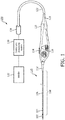
- Fig. 1 is a schematic diagram of an intraluminal imaging system 100 according to embodiments of the present disclosure.
- the system 100 may include an intraluminal imaging device 110, a connector 124, a control and processing system 130, for example, a console and a computer, and a monitor 132.
- the intraluminal imaging device 110 includes an imaging assembly 102 at the tip of a flexible elongate member 108, and a handle 120.
- the flexible elongate member 108 includes a distal portion 104 and a proximal portion 106.
- the distal end of the distal portion 104 is attached to the imaging assembly 102.
- the proximal end of the proximal portion 106 is attached to the handle 120, for example, by a resilient strain reliever 112.
- the handle 120 may be used for manipulation of the intraluminal imaging device 110 and manual control of the intraluminal imaging device 110.
- the imaging assembly 102 can include an imaging core with ultrasound transducer elements and associated circuitry.
- the handle 120 can include actuators 116, a clutch 114, and other steering control components for steering the intraluminal imaging device 110.
- the steering may include deflecting the imaging assembly 102 and the distal portion 104, as described in greater details herein.
- the handle 120 is connected to the connector 124 via another strain reliever 118 and a connection cable 122.
- the connector 124 may be configured to provide suitable configurations for interconnecting the control and processing system 130 and the monitor 132 to the imaging assembly 102.
- the control and processing system 130 may be used for processing, storing, analyzing, and manipulating data, and the monitor 132 may be used for displaying obtained signals generated by the imaging assembly 102.
- the control and processing system 130 can include one or more processors, memory, one or more input devices, such as keyboards and any suitable command control interface device.
- the control and processing system 130 can be operable to facilitate the features of the intraluminal imaging system 100 described herein.
- a processor can execute computer readable instructions stored on the non-transitory tangible computer readable medium.
- the monitor 132 can be any suitable display device, such as liquid-crystal display (LCD) panel or the like.
- a physician or a clinician may advance the flexible elongate member 108 into a vessel within a heart anatomy.
- the physician or clinician can steer the flexible elongate member 108 to a position near the area of interest to be imaged.
- one actuator 116 may deflect the imaging assembly 102 and the distal portion 104 in a left-right plane and the other actuator 116 may deflect the imaging assembly 102 and the distal portion 104 in an anterior-posterior plane, as discussed in greater details herein.
- the clutch 114 provides a locking mechanism to lock the positions of the actuators 116 and in effect lock the deflection of the flexible elongate member while imaging the area of interest.
- the imaging process may include activating the ultrasound transducer elements on the imaging assembly 102 to produce ultrasonic energy. A portion of the ultrasonic energy is reflected by the area of interest and the surrounding anatomy, and the ultrasound echo signals are received by the ultrasound transducer elements.
- the connector 124 transfers the received echo signals to the control and processing system 130 where the ultrasound image is reconstructed and displayed on the monitor 132.
- the control processing system 130 can control the activation of the ultrasound transducer elements and the reception of the echo signals.
- the control and processing system 130 and the monitor 132 may be part of a same system.
- the system 100 may be utilized in a variety of applications such as transseptal punctures, left atrial appendage closures, atrial fibrillation ablation, and valve repairs and can be used to image vessels and structures within a living body.
- the system 100 is described in the context of intraluminal imaging procedures, the system 100 is suitable for use with any catheterization procedure, e.g., ICE.
- the imaging assembly 102 may include any suitable physiological sensor or component for diagnostic, treatment, and/or therapy.
- the imaging assembly can include an imaging component, an ablation component, a cutting component, a morcellation component, a pressure-sensing component, a flow-sensing component, a temperature-sensing component, and/or combinations thereof.
- the intraluminal imaging device 110 includes a flexible elongate member108 that can be positioned within a vessel.
- the flexible elongate member 108 may have a distal portion 104 and a proximal portion 106.
- the intraluminal imaging device 110 includes an imaging assembly 102 that is mounted within the distal portion 104 of the flexible elongate member 108.
- the intraluminal imaging system 100 is used for generating 2D and 3D images. In some examples, the intraluminal imaging system 100 is used for generating X-plane images at two different viewing directions perpendicular to each other.
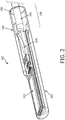
- Fig. 2 is a perspective view of the imaging assembly 102 described above with respect to Fig.1 .
- the imaging assembly 102 may include the imaging core 262 that is positioned within a tip member 200.
- the imaging core 262 is coupled to an electrical cable 266 via an electrical interconnection 264.
- the electrical cable 266 extends through the alignment portion 244 and the interface portion 246 of the inner cavity 250.
- the electrical cable 266 can further extend through the flexible elongate member 108 as shown in Fig. 1 .
- the configuration and structure of the tip member 200 described above provide several benefits.
- the benefits include providing safe and easy delivery of the catheter, providing improved tensile strength for steering and navigation, providing consistent alignment, and providing improved image quality.
- the outer geometry of the tip member 200 is configured to provide smooth surfaces and smooth edges with small radii.
- the smooth edges reduce friction when the tip member 200 traverses a vessel during insertion.
- the smooth surfaces prevent tears and/or damages to tissue structures during the insertion.
- the smooth edges and smooth surfaces can facilitate crossing of a septum or other anatomical feature during a catheterization procedure.
- the material type and the wall thickness of the tip member 200 are selected to minimize acoustic distortion, attenuation, and/or reflection.
- the internal geometry of the tip member 200 is configured to facilitate alignment during manufacturing.
- the tip member 200 can also include other features, for example, a guidewire lumen, one or more holes, or other geometry to accommodate additional devices or features such as pressure sensors, drug delivery mechanisms, and/or any suitable interventional features.
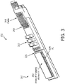
- Fig. 3 is a top view of the imaging assembly 102 according to embodiments of the present disclosure.
- the imaging assembly 102 may include the imaging core 262 having an array of imaging elements 302 and micro-beam-former IC 304 that can be coupled to the array of imaging elements 302.
- the imaging assembly 102 also shows the electrical cable 266 coupled to the electrical interconnection 264.
- the electrical cable 266 is further coupled through an interposer 310 to the micro-beam-former IC 304.
- the interposer 310 is connected to the micro-beam-former IC 304 through wire bonding 320.
- the array of imaging elements 302 is an array of ultrasound imaging transducers that are directly flip-chip mounted to the micro-beam-former IC 304.
- the transmitters and receivers of the ultrasound imaging transducers are on the micro-beam-former IC 304 and are directly attached to the transducers.
- a mass termination of the acoustic elements are done at the micro-beam-former IC 304.
- the imaging assembly 102 includes an array of imaging elements 302 in the form of an array of more than 800 imaging elements and the electrical cable 266 includes a total of 12 signal lines or less. In some examples, the electrical cable 266 includes a total of 30 lines or less that includes the signal lines, power lines, and control lines.
- an array of imaging elements for example a 1D or 2D array, may include between 32 to 1000 imaging elements.
- the array can include 32, 64, 128, 256, 512, 640, 768, or any other suitable number of imaging elements.
- a 1D array may have 32 imaging elements.
- a 2D array may have 32, 64, or more imaging elements.
- the number of signal lines are between 10 and 20, for example, 12 signal lines, 16 signal lines, or any other suitable number of signal lines.
- AID array can be configured to generate 2D images.
- a 2D array can be configured to generate 2D and/or 3D images.
- the imaging assembly 102 include an ultrasound transducer array with fewer than 30 wires connecting to the control and imaging system 130.
- the 30 wires or less include 6-12 signal lines, preferably include 8 signal lines.
- the transducer array is capable of 2D and 3D imaging. Additional aspects of the intraluminal imaging system includes a micro-beam-forming IC 304 with enough signal processing power to reduce the number of required ultrasound signal lines to a fraction of the total wires that include power and control lines.
- the electrical cable 266 of the imaging assembly 102 is directly coupled to the micro-beam-former IC 304 of the imaging assembly 102.
- the micro-beam-forming IC 304 lies directly underneath the array of acoustic elements 302 and is electrically connected to them.
- the array acoustic elements 302 may be piezoelectric or micromachined ultrasonic transducer (MUT) elements.
- piezoelectric elements are attached to the IC 304 by flip-chip mounting of an assembly of acoustic layers that include sawing into individual elements.
- MUT elements may be flip-chip mounted as a unit or grown directly on top of the micro-beam-forming IC 304.
- the cable bundle may be terminated directly to the micro-beam-forming IC 304, or may be terminated to an interposer 310 of suitable material such as a rigid or flexible printed circuit assembly.
- the interposer 310 may then be connected to the micro-beam-forming IC 304 via any suitable means such as wire bondings 320.
- Fig. 4 is a schematic diagram 400 illustrating the beam-forming of an intraluminal imaging device according to embodiments of the present disclosure.
- the diagram 400 includes the imaging assembly 102 that includes the array of imaging elements 302 and micro-beam-former IC 304.
- the micro-beam-former IC 304 can be coupled to the array of imaging elements 302 at the distal portion of an intraluminal imaging device (e.g., intraluminal imaging device 110).
- the array of imaging elements 302 is divided into one or more subarrays of imaging elements 420.
- the array of imaging elements 302 are divided into 9 subarrays of imaging elements 420 that each has 16 imaging elements arranged as 4 by 4.
- the imaging assembly 102 also has the micro-beam-former IC 304 that includes a plurality of microchannels 430 that each can separately beam-form the signals received from imaging elements of a corresponding subarray 420.
- the microchannels 430 each comprise a delay for alignment of the signals received from the imaging elements of a subarray 420.
- the microchannels delay lines 430 of each subarray of imaging elements 420 are separately coupled to one coaxial cable 410 such that the received signals of each subarray of imaging elements 420 are transferred through a separate channel, e.g., coaxial cable 410, to the control and processing system 130.
- the imaging assembly 102 includes an array of imaging elements 302.
- the array of imaging elements 302 can include two or more subarrays of imaging elements 420 of imaging elements.
- the imaging assembly 102 includes a micro-beam-former integrated circuit (IC) 304 coupled to the array of imaging elements.
- IC micro-beam-former integrated circuit
- the micro-beam-former integrated circuit (IC) 304 can control the array of imaging elements 302 and can perform beam forming for a plurality of imaging elements of each subarrays of imaging elements 420 of the array of imaging elements 302.
- the imaging assembly 102 includes a cable 266 that includes two or more signal lines that are coupled to the micro-beam-former IC 304.
- Each of signal lines is associated with one of the subarrays of imaging elements 420 of the array of imaging elements 302 to transfer beam formed imaging signals of the associated subarray.
- each signal line corresponds to a particular subarray 420 and is configured to receive the beam-formed signals specific to the corresponding subarray.
- the electrical cable 266 further includes one or more power lines for feeding power to the micro-beam-former IC 304 and one or more control lines for communicating control signals to the micro-beam-former IC 304.
- imaging assembly 102 includes an array of imaging elements 302 in the form of an array of more than 800 imaging elements such that the array of imaging elements is divided into no more than 12 subarrays of imaging elements 420 and the cable 410 includes no more than 12 signal lines, each signal line associated with one subarray of imaging elements 420.
- the array of imaging elements 302 is a two dimensional array. In some examples, the array of imaging elements 302 is symmetric such that it has equal number of rows of imaging elements and columns of imaging elements. In some other examples, the array of imaging elements 302 is asymmetric such that it has different number of rows of imaging elements and columns of imaging elements.
- the micro-beam-former IC 304 includes multiple microchannel delay lines 430.
- the microchannel delay lines 430 are used to perform the beam forming for the plurality of imaging elements of each of the two or more subarrays of imaging elements 420.
- the multiple microchannel delay lines 430 include at least one of a charge coupled device, an analog random access memory, or a tapped analog delay line.
- the first beam-formed signals and the second beam-formed signals are transmitted via a connection cable to a control and processing system 130 of Figs. 1 and 4 .
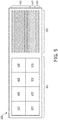
- Fig. 5 is a schematic diagram illustrating aspects of an intraluminal imaging device according to embodiments of the present disclosure.
- the diagram 500 is consistent with imaging assemble 102 of Figs. 1-4 that includes the array of imaging elements 302 and micro-beam-former IC 304. As shown, the array of imaging elements 302 is divided into subarrays of imaging elements 420. For example, the array of imaging elements 302 is divided into 8 subarrays of imaging elements 420.
- the imaging assembly 500 also shows the cable 530 which is consistent with the cables 410 and 266 in Figs. 3 and 4 and includes 8 signal lines 505, two control lines 510 and 2 power lines 520.
- each signal line is associated with on subarry of imaging elements 420 such that the received signals of each subarray of imaging elements 420 are transferred through a separate signal lines 505 that can be consistent with the coaxial cable 410 of Fig. 4 to the control and processing system 130.
- the power lines 520 /control lines 510 can be coupled to one or more subarray of imaging elements 420 and can provide power/control one or more subarray of imaging elements 420.
- the overall aperture is divided into subarrays of imaging elements 420 each of which is independently beam-formed.
- a 2D array of imaging elements 302 is shown which can also be used for 3D imaging.
- the essential element in the micro-beam-former IC 304 is the delay in each microchannel 430. The delay is used to time-align the echoes received by each element in the subarray of imaging elements 420 so that the signals add constructively in the desired beam direction, but destructively in other directions.
- the delay may be of any convenient sort of controlled variable delay, such as charge coupled devices (CCD's), analog RAM, tapped analog delay lines, etc.
- the area of a subarray of imaging elements 420 is proportional to the square of its dimension, so the maximum subarray area A is proportional to the square of the available delay: A ⁇ ⁇ 2
- each subarray of imaging elements 420 feeds one signal line through a single wire, thus, the number N of ultrasound signal wires required in the cable is inversely proportional to the square of the available delay: N ⁇ 1 ⁇ 2
- the delay elements in use consist of a number of repeated elements, and the number of these elements determines the maximum available delay. Since the acoustic array is flip-chip mounted to the micro-beam-former IC 304, all of the processing, including the delay, for any given element can reside in the area occupied by that one element.
- an ultrasound imaging catheter 2D array may have 1000 or more elements, so the number of ultrasound signal wires required would be in the range of 30 to 50, and 15 to 20 power and control lines might also be needed. This number of wires is typical in existing 1D ultrasound imaging catheters that use unshielded single wires rather than coaxial, and are individually attached to the acoustic elements.
- the use of single wires rather than coax degrades the image due to noise susceptibility and crosstalk between the unshielded wires.
- the connections typically can be made to one narrow end of 2.5 mm, and so are limited to about 30 at most, including all of the ultrasonic signal lines, power lines, and control lines.
- newer IC processing equipment is now available which can approximately double the available amount of delay for the imaging signals, e.g., transducer signals.
- the number of ultrasound signal wires could be reduced by about a factor of 4, to e.g., between 8 and 12.
- the total number of wires required is then in the range of 20 to 30, which is in the range of what that can be connected to the micro-beam-former IC 304, and allows the use of coaxial cables.
- the reduced wire count has a number of advantages that include: having fewer interconnects in the flexible elongate member 108 tip, e.g., the catheter tip, decreases manufacturing cost and increases yield, and larger subarrays can track the depth of the received focal point in time.
- a possibly digital second beam-forming stage can be used that would further reduce the channel count.
- cable count can further be reduced by implementing on-chip power regulation, sharing functions of wires, and using programmable autonomous IC controllers to reduce the number of power lines and control lines.
- Fig. 6 provides a flow diagram illustrating a method 600 of intraluminal imaging of a vessel.
- the method 600 includes a number of enumerated steps, but embodiments of the method 600 may include additional steps before, after, and in between the enumerated steps. In some embodiments, one or more of the enumerated steps may be omitted, performed in a different order, or performed concurrently.
- the method 600 can be performed with reference to Figs. 1 , 2 , 3 , and 4 .
- ultrasound signals are received at an array of imaging elements, e.g., the array of imaging elements 302.
- the array of imaging elements 302 can be positioned within the distal portion 104 of an intraluminal imaging device 110.
- a micro-beam-former IC 304 is directly coupled to the array of imaging elements 302 and transmits and receives imaging signals, e.g., ultrasound signals.
- the ultrasound signals received by the first subarray of the array of imaging elements 302 are beam-formed.
- the beam-forming can be performed with reference to Figs. 3 and 4 .
- the micro-beam-former IC 304 is coupled, e.g., from beneath, to the array of imaging elements 302.
- the micro-beam-former IC 304 can command the array of imaging elements 302 and can transmit and receive signals, e.g., ultrasound signals.
- the array of imaging elements 302 are divided into a plurality of subarrays of imaging elements 420 including the first subarray.
- the micro-beam-former IC 304 can also include a plurality microchannels delay lines 430.
- the micro-beam-former IC 304 can supply the required delays for beam-forming from one of the microchannels delay lines 430 to the first subarray to provide beam-forming for the first subarray such that the beam-forming is provided by applying the required delays to the signals of each of the plurality of the imaging elements of the first subarray.
- the beam-forming is performed during both transmitting and receiving. In some other examples, the beam-forming is performed during the receiving.
- the ultrasound signals received by the plurality of imaging elements of the first subarray of the array of imaging elements are beam-formed by applying the required delays to construct a first beam-formed signal.
- the ultrasound signals received by the second subarray of the array of imaging elements 302 are beam-formed.
- the beam-forming can be performed with reference to Figs. 3 and 4 .
- the micro-beam-former IC 304 can supply the required delays for beam-forming from one of the microchannels delay lines 430 to the second subarray to provide beam-forming for the second subarray such that the beam-forming is provided by applying the required delays to the signals of each of the plurality of the imaging elements of the second subarray.
- the ultrasound signals received by the plurality of imaging elements of the second subarray of the array of imaging elements are beam-formed by applying the required delays to construct a second beam-formed signal.
- the first beam-formed signal is transmitted over a first signal line of a cable of the intraluminal imaging device.
- This step can be performed with reference to Fig. 4 .
- the beam-formed signal is constructed by applying the required beam-forming delays provided by a microchannels delay line 430 of the micro-beam-former IC 304 to the received signals of the first subarray of imaging elements 420 and then transmitting a collection of the received and delayed signals of the first subarray of imaging elements 420 through the cable, e.g., coaxial cable 410 to the control and processing system 130.
- the second beam-formed signal is transmitted over a second signal line of a cable of the intraluminal imaging device.
- the beam-formed signal is constructed by applying the required beam-forming delays provided by a microchannels delay line 430 of the micro-beam-former IC 304 to the received signals of the second subarray of imaging elements 420 and then transmitting a collection of the received and delayed signals of the second subarray 420 through a cable, e.g., a coaxial cable to the control and processing system 130.
- the control and processing system 130 receives a plurality of the beam-formed signals from a plurality of the subarrays and constructs 2D and 3D images.
- the largest number of connections to a typical micro-beam-former IC 304 are the analog channel lines which carry the micro-beam-formed received signals back to the imaging system, and possibly transmit signals from the system 100 to the micro-beam-former IC.
- large micro-beam-forming delays are produced on micro-beam-former IC 304 to reduce the number of analog channel lines compared to the existing micro-beam-former technology, thereby reducing the number of connections to the micro-beam-former IC 304 and the number of wires required to connect the imaging assembly 102 to the control and processing system 130.
- the reduced wire count has a number of advantages that include: reduced materials and assembly cost, reducing manufacturing cost and increasing yield, use of coaxial cables for transferring the signals and thus decreasing susceptibility to noise and crosstalk between channels that can degrade the image, ability to use larger wire size due to smaller number of wires and thus increasing reliability, providing 3D imaging capability, simplifying interconnect from the cable to the micro-beam-forming IC, and providing the potential for automating the interconnect processes.
Claims (13)
- Eine Bildgebungsbaugruppe (102) für ein intraluminales Bildgebungsgerät (110), die Folgendes umfasst:eine Bildgebungsanordnung, die am distalen Abschnitt des intraluminalen Bildgebungsgeräts angebracht ist und mehrere Bildgebungselemente (320) umfasst, die in mehreren Unteranordnungen (420) angeordnet sind;eine integrierte Mikrobeamformer-Schaltung, IC, (304), die am distalen Abschnitt des intraluminalen Bildgebungsgeräts angebracht ist und mehrere Mikrokanäle umfasst, die für die von den Bildgebungselementen von mindestens zwei Unteranordnungen der mehreren Unteranordnungen empfangenen Signale jeweils ein separates Beamforming durchführen, wobei es sich bei den Bildgebungselementen um Ultraschallwandler handelt, die an der Mikrobeamformer-IC angebracht sind; undmindestens zwei Signalleitungen (505), die mit der Mikrobeamformer-IC (304) verbunden sind, wobei die einzelnen Signalleitungen jeweils einer Unteranordnung der mindestens zwei Unteranordnungen entsprechen und die strahlgeformten Signale für die jeweiligen Unteranordnungen abrufen.
- Die Baugruppe (102) gemäß Anspruch 1, wobei sich die Mikrobeamformer-IC direkt unter der Bildgebungsanordnung befindet und elektrisch mit den Ultraschallwandlern verbunden ist.
- Die Baugruppe (102) gemäß Anspruch 1 oder 2, wobei die mindestens zwei Signalleitungen in ein Kabel (266) integriert sind, das von der Mikrobeamformer-IC (304) durch einen Ausrichtungsabschnitt 244 sowie einen Schnittstellenabschnitt 246 des inneren Hohlraums 250 sowie anschließend zudem durch ein flexibles längliches Element (108) des intraluminalen Bildgebungsgeräts (110) zum proximalen Abschnitt des intraluminalen Bildgebungsgeräts verläuft.
- Die Baugruppe (102) gemäß Anspruch 1, wobei die Mikrokanäle jeweils eine Verzögerung zum Ausrichten der von den Bildgebungselementen (320) der Unteranordnung empfangenen Signale umfassen.
- Die Baugruppe (102) gemäß Anspruch 1, die zudem ein Kabel (266) umfasst, das die mindestens zwei Signalleitungen umfasst, wobei das Kabel zudem mindestens eine Stromleitung zum Zuführen von Strom zur Mikrobeamformer-IC (304) umfasst.
- Die Baugruppe (102) gemäß Anspruch 5, wobei das Kabel (266) zudem mindestens eine Steuerungsleitung für das Übertragen von Steuerungssignalen an die Mikrobeamformer-IC (304) umfasst.
- Die Baugruppe (102) gemäß Anspruch 1, wobei das intraluminale Bildgebungsgerät (110) 2D- und 3D-Bilder erzeugt.
- Die Baugruppe (102) gemäß Anspruch 1, die zudem ein Kabel (266) umfasst, das die mindestens zwei Signalleitungen (505) umfasst, wobei die Bildgebungsbaugruppe eine Anordnung mit mehr als 512 Elementen umfasst, und wobei das Kabel insgesamt höchstens 16 Signalleitungen umfasst, und
wobei das Kabel optional insgesamt höchstens 30 Leitungen umfasst, zu denen die Signalleitungen, die Stromleitungen und die Steuerungsleitungen zählen. - Die Baugruppe (102) gemäß Anspruch 1, die zudem ein Kabel (266) umfasst, das die mindestens zwei Signalleitungen umfasst, wobei das Kabel (266) direkt mit der Mikrobeamformer-IC (304) verbunden ist.
- Die Baugruppe (102) gemäß Anspruch 1, die zudem ein Kabel (266) umfasst, das die mindestens zwei Signalleitungen umfasst, wobei das Kabel mit einem mit der Mikrobeamformer-IC (304) verbundenen Interposer (310) verbunden ist.
- Die Baugruppe (102) gemäß Anspruch 10, wobei der Interposer (310) verdrahtet mit der Mikrobeamformer-IC (304) verbunden ist.
- Die Baugruppe (102) gemäß Anspruch 1, wobei die Mikrobeamformer-IC (304) mehrere Mikrokanal-Verzögerungsleitungen umfasst, wobei die Mikrokanal-Verzögerungsleitungen verwendet werden, um das Beam-forming für die mehreren Bildgebungselemente (320) der einzelnen der mindestens zwei Unteranordnungen von Bildgebungselementen durchzuführen.
- Die Baugruppe (102) gemäß Anspruch 12, wobei die mehreren Mikrokanal-Verzögerungsleitungen mindestens ein Element aus einer Gruppe umfasst, die aus einem ladungsgekoppelten Gerät, einem analogen Direktzugriffsspeicher oder einer analogen Hauptverzögerungsleitung besteht.
Applications Claiming Priority (3)
| Application Number | Priority Date | Filing Date | Title |
|---|---|---|---|
| US201662403311P | 2016-10-03 | 2016-10-03 | |
| US201662437778P | 2016-12-22 | 2016-12-22 | |
| PCT/EP2017/074278 WO2018065254A1 (en) | 2016-10-03 | 2017-09-26 | Intraluminal imaging devices with a reduced number of signal channels |
Publications (2)
| Publication Number | Publication Date |
|---|---|
| EP3518774A1 EP3518774A1 (de) | 2019-08-07 |
| EP3518774B1 true EP3518774B1 (de) | 2021-09-01 |
Family
ID=59974424
Family Applications (1)
| Application Number | Title | Priority Date | Filing Date |
|---|---|---|---|
| EP17777002.1A Active EP3518774B1 (de) | 2016-10-03 | 2017-09-26 | Vorrichtungen zur intraluminalen bildgebung mit einer reduzierten anzahl von signalkanälen |
Country Status (4)
| Country | Link |
|---|---|
| US (1) | US11911217B2 (de) |
| EP (1) | EP3518774B1 (de) |
| JP (1) | JP7096237B2 (de) |
| WO (1) | WO2018065254A1 (de) |
Families Citing this family (1)
| Publication number | Priority date | Publication date | Assignee | Title |
|---|---|---|---|---|
| AU2019328805A1 (en) * | 2018-08-31 | 2021-04-22 | National University Of Ireland Galway | Ultrasound based three-dimensional lesion verification within a vasculature |
Family Cites Families (30)
| Publication number | Priority date | Publication date | Assignee | Title |
|---|---|---|---|---|
| US8241217B2 (en) * | 1995-06-29 | 2012-08-14 | Teratech Corporation | Portable ultrasound imaging data |
| US6669633B2 (en) * | 1999-06-22 | 2003-12-30 | Teratech Corporation | Unitary operator control for ultrasonic imaging graphical user interface |
| US6468216B1 (en) | 2000-08-24 | 2002-10-22 | Kininklijke Philips Electronics N.V. | Ultrasonic diagnostic imaging of the coronary arteries |
| US20050131299A1 (en) * | 2003-12-10 | 2005-06-16 | Brent Robinson | Differential partial beamforming |
| US20050131302A1 (en) * | 2003-12-16 | 2005-06-16 | Poland Mckee D. | Ultrasonic probe having a selector switch |
| US20050203410A1 (en) * | 2004-02-27 | 2005-09-15 | Ep Medsystems, Inc. | Methods and systems for ultrasound imaging of the heart from the pericardium |
| EP1737348A1 (de) * | 2004-04-14 | 2007-01-03 | Koninklijke Philips Electronics N.V. | Ultraschall-sonde mit weitem sichtfeld |
| JP4477631B2 (ja) * | 2004-06-11 | 2010-06-09 | オリンパス株式会社 | 超音波プローブ装置及び超音波診断装置 |
| EP1797456A1 (de) * | 2004-09-30 | 2007-06-20 | Koninklijke Philips Electronics N.V. | Mikrostrahlformungs-wandler-architektur |
| JP2007068918A (ja) * | 2005-09-09 | 2007-03-22 | Fujifilm Corp | 超音波プローブ、および超音波診断装置 |
| EP1952175B1 (de) * | 2005-11-02 | 2013-01-09 | Visualsonics, Inc. | Digitaler Sendebündelformer für ein Ultraschallgruppenstrahlersystem |
| WO2008054395A1 (en) * | 2006-11-03 | 2008-05-08 | Research Triangle Institute | Enhanced ultrasound imaging probes using flexure mode piezoelectric transducers |
| US20080146940A1 (en) * | 2006-12-14 | 2008-06-19 | Ep Medsystems, Inc. | External and Internal Ultrasound Imaging System |
| US8052607B2 (en) * | 2008-04-22 | 2011-11-08 | St. Jude Medical, Atrial Fibrillation Division, Inc. | Ultrasound imaging catheter with pivoting head |
| JP5433429B2 (ja) * | 2010-01-12 | 2014-03-05 | 株式会社東芝 | 超音波プローブ |
| JP5452319B2 (ja) * | 2010-03-31 | 2014-03-26 | 富士フイルム株式会社 | 超音波診断装置 |
| US20120095348A1 (en) * | 2010-10-19 | 2012-04-19 | Sonavation, Inc. | Three Dimensional Imaging Intra Cardiac Echocardiography (ICE) Catheter |
| KR20140004667A (ko) * | 2010-12-03 | 2014-01-13 | 리써치 트라이앵글 인스티튜트 | 초음파 장치 및 관련 케이블 어셈블리 |
| KR101303626B1 (ko) * | 2011-01-06 | 2013-09-11 | 서강대학교산학협력단 | 피사체를 진단하는 진단시스템, 피사체에 대한 진단영상을 제공하는 의료영상시스템 및 피사체에 대한 진단영상을 표시하는 방법 |
| NL2008459C2 (en) * | 2012-03-09 | 2013-09-10 | Oldelft B V | A method of manufacturing an ultrasound transducer for use in an ultrasound imaging device, and an ultrasound transducer and ultrasound probe manufactured according to the method. |
| WO2014080312A1 (en) * | 2012-11-20 | 2014-05-30 | Koninklijke Philips N.V. | Frameless ultrasound probes with heat dissipation |
| US20140180120A1 (en) * | 2012-12-21 | 2014-06-26 | Volcano Corporation | Ultrasound Imaging Catheters with Reciprocating Phased Array Transducers |
| CA2896516A1 (en) * | 2012-12-31 | 2014-07-03 | Volcano Corporation | Stepped banded connector for intravascular ultrasound devices |
| CN105339097B (zh) * | 2013-06-26 | 2018-07-10 | 皇家飞利浦有限公司 | 针对超声换能器阵列的集成电路布置 |
| WO2015048321A1 (en) * | 2013-09-25 | 2015-04-02 | Georgia Tech Research Corporation | Mri compatible 3-d intracardiac echography catheter and system |
| US10586753B2 (en) * | 2014-03-31 | 2020-03-10 | Koninklijke Philips N.V. | IC die, ultrasound probe, ultrasonic diagnostic system and method |
| KR20150118750A (ko) * | 2014-04-15 | 2015-10-23 | 삼성전자주식회사 | 초음파 영상 장치 |
| US10537309B2 (en) * | 2014-11-13 | 2020-01-21 | Duke University | Systems and methods for ultrasound motion display and analysis |
| US10864551B2 (en) * | 2014-12-15 | 2020-12-15 | Koninklijke Philips, N.V. | Compact ultrasound transducer with direct coax attachment |
| US20180064415A1 (en) * | 2016-09-07 | 2018-03-08 | Siemens Medical Solutions Usa, Inc. | Acoustic ablation assisted intra-cardiac echocardiography catheter |
-
2017
- 2017-09-26 JP JP2019517397A patent/JP7096237B2/ja active Active
- 2017-09-26 WO PCT/EP2017/074278 patent/WO2018065254A1/en active Application Filing
- 2017-09-26 EP EP17777002.1A patent/EP3518774B1/de active Active
- 2017-09-26 US US16/338,855 patent/US11911217B2/en active Active
Also Published As
| Publication number | Publication date |
|---|---|
| US11911217B2 (en) | 2024-02-27 |
| JP2019528975A (ja) | 2019-10-17 |
| WO2018065254A1 (en) | 2018-04-12 |
| US20200214670A1 (en) | 2020-07-09 |
| EP3518774A1 (de) | 2019-08-07 |
| JP7096237B2 (ja) | 2022-07-05 |
Similar Documents
| Publication | Publication Date | Title |
|---|---|---|
| US20080025145A1 (en) | Ultrasound Imaging Probe Featuring Wide Field of View | |
| EP3537984B1 (de) | Drahtlose intraluminale bildgebungsvorrichtung und zugehörige vorrichtungen, systeme und verfahren | |
| US20220409171A1 (en) | Intra-cardiac echocardiography inteposer | |
| US20230397904A1 (en) | Ultrasound imaging device with thermally conductive plate | |
| JP2023078378A (ja) | 管腔内超音波検査のための撮像面の制御及び表示、並びに関連するデバイス、システム及び方法 | |
| US20190247017A1 (en) | Inner member for intravascular imaging device and associated devices, systems, and methods | |
| EP3600699B1 (de) | Steuergerät für ringförmige integrierte schaltung für intraluminale ultraschallbildgebungsvorrichtung | |
| EP3518774B1 (de) | Vorrichtungen zur intraluminalen bildgebung mit einer reduzierten anzahl von signalkanälen | |
| US20200275909A1 (en) | Connectors for patient interface module and ultrasound imaging device | |
| JP7167011B2 (ja) | 非対称開口用のx平面撮像及び3d撮像 |
Legal Events
| Date | Code | Title | Description |
|---|---|---|---|
| STAA | Information on the status of an ep patent application or granted ep patent |
Free format text: STATUS: UNKNOWN |
|
| STAA | Information on the status of an ep patent application or granted ep patent |
Free format text: STATUS: THE INTERNATIONAL PUBLICATION HAS BEEN MADE |
|
| PUAI | Public reference made under article 153(3) epc to a published international application that has entered the european phase |
Free format text: ORIGINAL CODE: 0009012 |
|
| STAA | Information on the status of an ep patent application or granted ep patent |
Free format text: STATUS: REQUEST FOR EXAMINATION WAS MADE |
|
| 17P | Request for examination filed |
Effective date: 20190503 |
|
| AK | Designated contracting states |
Kind code of ref document: A1 Designated state(s): AL AT BE BG CH CY CZ DE DK EE ES FI FR GB GR HR HU IE IS IT LI LT LU LV MC MK MT NL NO PL PT RO RS SE SI SK SM TR |
|
| AX | Request for extension of the european patent |
Extension state: BA ME |
|
| DAV | Request for validation of the european patent (deleted) | ||
| DAX | Request for extension of the european patent (deleted) | ||
| STAA | Information on the status of an ep patent application or granted ep patent |
Free format text: STATUS: EXAMINATION IS IN PROGRESS |
|
| RAP1 | Party data changed (applicant data changed or rights of an application transferred) |
Owner name: KONINKLIJKE PHILIPS N.V. |
|
| 17Q | First examination report despatched |
Effective date: 20200318 |
|
| STAA | Information on the status of an ep patent application or granted ep patent |
Free format text: STATUS: EXAMINATION IS IN PROGRESS |
|
| GRAP | Despatch of communication of intention to grant a patent |
Free format text: ORIGINAL CODE: EPIDOSNIGR1 |
|
| STAA | Information on the status of an ep patent application or granted ep patent |
Free format text: STATUS: GRANT OF PATENT IS INTENDED |
|
| INTG | Intention to grant announced |
Effective date: 20210326 |
|
| RIN1 | Information on inventor provided before grant (corrected) |
Inventor name: DAVIES, STEPHEN, CHARLES Inventor name: SUDOL, WOJTEK Inventor name: SAVORD, BERNARD JOSEPH Inventor name: OSSMANN, WILLIAM |
|
| GRAS | Grant fee paid |
Free format text: ORIGINAL CODE: EPIDOSNIGR3 |
|
| GRAA | (expected) grant |
Free format text: ORIGINAL CODE: 0009210 |
|
| STAA | Information on the status of an ep patent application or granted ep patent |
Free format text: STATUS: THE PATENT HAS BEEN GRANTED |
|
| AK | Designated contracting states |
Kind code of ref document: B1 Designated state(s): AL AT BE BG CH CY CZ DE DK EE ES FI FR GB GR HR HU IE IS IT LI LT LU LV MC MK MT NL NO PL PT RO RS SE SI SK SM TR |
|
| REG | Reference to a national code |
Ref country code: GB Ref legal event code: FG4D |
|
| REG | Reference to a national code |
Ref country code: CH Ref legal event code: EP Ref country code: AT Ref legal event code: REF Ref document number: 1425355 Country of ref document: AT Kind code of ref document: T Effective date: 20210915 |
|
| REG | Reference to a national code |
Ref country code: DE Ref legal event code: R096 Ref document number: 602017045248 Country of ref document: DE |
|
| REG | Reference to a national code |
Ref country code: IE Ref legal event code: FG4D |
|
| REG | Reference to a national code |
Ref country code: LT Ref legal event code: MG9D |
|
| REG | Reference to a national code |
Ref country code: NL Ref legal event code: MP Effective date: 20210901 |
|
| PG25 | Lapsed in a contracting state [announced via postgrant information from national office to epo] |
Ref country code: SE Free format text: LAPSE BECAUSE OF FAILURE TO SUBMIT A TRANSLATION OF THE DESCRIPTION OR TO PAY THE FEE WITHIN THE PRESCRIBED TIME-LIMIT Effective date: 20210901 Ref country code: RS Free format text: LAPSE BECAUSE OF FAILURE TO SUBMIT A TRANSLATION OF THE DESCRIPTION OR TO PAY THE FEE WITHIN THE PRESCRIBED TIME-LIMIT Effective date: 20210901 Ref country code: HR Free format text: LAPSE BECAUSE OF FAILURE TO SUBMIT A TRANSLATION OF THE DESCRIPTION OR TO PAY THE FEE WITHIN THE PRESCRIBED TIME-LIMIT Effective date: 20210901 Ref country code: LT Free format text: LAPSE BECAUSE OF FAILURE TO SUBMIT A TRANSLATION OF THE DESCRIPTION OR TO PAY THE FEE WITHIN THE PRESCRIBED TIME-LIMIT Effective date: 20210901 Ref country code: BG Free format text: LAPSE BECAUSE OF FAILURE TO SUBMIT A TRANSLATION OF THE DESCRIPTION OR TO PAY THE FEE WITHIN THE PRESCRIBED TIME-LIMIT Effective date: 20211201 Ref country code: NO Free format text: LAPSE BECAUSE OF FAILURE TO SUBMIT A TRANSLATION OF THE DESCRIPTION OR TO PAY THE FEE WITHIN THE PRESCRIBED TIME-LIMIT Effective date: 20211201 Ref country code: ES Free format text: LAPSE BECAUSE OF FAILURE TO SUBMIT A TRANSLATION OF THE DESCRIPTION OR TO PAY THE FEE WITHIN THE PRESCRIBED TIME-LIMIT Effective date: 20210901 Ref country code: FI Free format text: LAPSE BECAUSE OF FAILURE TO SUBMIT A TRANSLATION OF THE DESCRIPTION OR TO PAY THE FEE WITHIN THE PRESCRIBED TIME-LIMIT Effective date: 20210901 |
|
| REG | Reference to a national code |
Ref country code: AT Ref legal event code: MK05 Ref document number: 1425355 Country of ref document: AT Kind code of ref document: T Effective date: 20210901 |
|
| PG25 | Lapsed in a contracting state [announced via postgrant information from national office to epo] |
Ref country code: PL Free format text: LAPSE BECAUSE OF FAILURE TO SUBMIT A TRANSLATION OF THE DESCRIPTION OR TO PAY THE FEE WITHIN THE PRESCRIBED TIME-LIMIT Effective date: 20210901 Ref country code: LV Free format text: LAPSE BECAUSE OF FAILURE TO SUBMIT A TRANSLATION OF THE DESCRIPTION OR TO PAY THE FEE WITHIN THE PRESCRIBED TIME-LIMIT Effective date: 20210901 Ref country code: GR Free format text: LAPSE BECAUSE OF FAILURE TO SUBMIT A TRANSLATION OF THE DESCRIPTION OR TO PAY THE FEE WITHIN THE PRESCRIBED TIME-LIMIT Effective date: 20211202 |
|
| PG25 | Lapsed in a contracting state [announced via postgrant information from national office to epo] |
Ref country code: AT Free format text: LAPSE BECAUSE OF FAILURE TO SUBMIT A TRANSLATION OF THE DESCRIPTION OR TO PAY THE FEE WITHIN THE PRESCRIBED TIME-LIMIT Effective date: 20210901 |
|
| REG | Reference to a national code |
Ref country code: CH Ref legal event code: PL |
|
| REG | Reference to a national code |
Ref country code: BE Ref legal event code: MM Effective date: 20210930 |
|
| PG25 | Lapsed in a contracting state [announced via postgrant information from national office to epo] |
Ref country code: IS Free format text: LAPSE BECAUSE OF FAILURE TO SUBMIT A TRANSLATION OF THE DESCRIPTION OR TO PAY THE FEE WITHIN THE PRESCRIBED TIME-LIMIT Effective date: 20220101 Ref country code: SM Free format text: LAPSE BECAUSE OF FAILURE TO SUBMIT A TRANSLATION OF THE DESCRIPTION OR TO PAY THE FEE WITHIN THE PRESCRIBED TIME-LIMIT Effective date: 20210901 Ref country code: SK Free format text: LAPSE BECAUSE OF FAILURE TO SUBMIT A TRANSLATION OF THE DESCRIPTION OR TO PAY THE FEE WITHIN THE PRESCRIBED TIME-LIMIT Effective date: 20210901 Ref country code: RO Free format text: LAPSE BECAUSE OF FAILURE TO SUBMIT A TRANSLATION OF THE DESCRIPTION OR TO PAY THE FEE WITHIN THE PRESCRIBED TIME-LIMIT Effective date: 20210901 Ref country code: PT Free format text: LAPSE BECAUSE OF FAILURE TO SUBMIT A TRANSLATION OF THE DESCRIPTION OR TO PAY THE FEE WITHIN THE PRESCRIBED TIME-LIMIT Effective date: 20220103 Ref country code: NL Free format text: LAPSE BECAUSE OF FAILURE TO SUBMIT A TRANSLATION OF THE DESCRIPTION OR TO PAY THE FEE WITHIN THE PRESCRIBED TIME-LIMIT Effective date: 20210901 Ref country code: EE Free format text: LAPSE BECAUSE OF FAILURE TO SUBMIT A TRANSLATION OF THE DESCRIPTION OR TO PAY THE FEE WITHIN THE PRESCRIBED TIME-LIMIT Effective date: 20210901 Ref country code: CZ Free format text: LAPSE BECAUSE OF FAILURE TO SUBMIT A TRANSLATION OF THE DESCRIPTION OR TO PAY THE FEE WITHIN THE PRESCRIBED TIME-LIMIT Effective date: 20210901 Ref country code: AL Free format text: LAPSE BECAUSE OF FAILURE TO SUBMIT A TRANSLATION OF THE DESCRIPTION OR TO PAY THE FEE WITHIN THE PRESCRIBED TIME-LIMIT Effective date: 20210901 |
|
| REG | Reference to a national code |
Ref country code: DE Ref legal event code: R097 Ref document number: 602017045248 Country of ref document: DE |
|
| PG25 | Lapsed in a contracting state [announced via postgrant information from national office to epo] |
Ref country code: MC Free format text: LAPSE BECAUSE OF FAILURE TO SUBMIT A TRANSLATION OF THE DESCRIPTION OR TO PAY THE FEE WITHIN THE PRESCRIBED TIME-LIMIT Effective date: 20210901 |
|
| PLBE | No opposition filed within time limit |
Free format text: ORIGINAL CODE: 0009261 |
|
| STAA | Information on the status of an ep patent application or granted ep patent |
Free format text: STATUS: NO OPPOSITION FILED WITHIN TIME LIMIT |
|
| PG25 | Lapsed in a contracting state [announced via postgrant information from national office to epo] |
Ref country code: LU Free format text: LAPSE BECAUSE OF NON-PAYMENT OF DUE FEES Effective date: 20210926 Ref country code: IT Free format text: LAPSE BECAUSE OF FAILURE TO SUBMIT A TRANSLATION OF THE DESCRIPTION OR TO PAY THE FEE WITHIN THE PRESCRIBED TIME-LIMIT Effective date: 20210901 Ref country code: IE Free format text: LAPSE BECAUSE OF NON-PAYMENT OF DUE FEES Effective date: 20210926 Ref country code: DK Free format text: LAPSE BECAUSE OF FAILURE TO SUBMIT A TRANSLATION OF THE DESCRIPTION OR TO PAY THE FEE WITHIN THE PRESCRIBED TIME-LIMIT Effective date: 20210901 Ref country code: BE Free format text: LAPSE BECAUSE OF NON-PAYMENT OF DUE FEES Effective date: 20210930 |
|
| 26N | No opposition filed |
Effective date: 20220602 |
|
| PG25 | Lapsed in a contracting state [announced via postgrant information from national office to epo] |
Ref country code: SI Free format text: LAPSE BECAUSE OF FAILURE TO SUBMIT A TRANSLATION OF THE DESCRIPTION OR TO PAY THE FEE WITHIN THE PRESCRIBED TIME-LIMIT Effective date: 20210901 Ref country code: LI Free format text: LAPSE BECAUSE OF NON-PAYMENT OF DUE FEES Effective date: 20210930 Ref country code: CH Free format text: LAPSE BECAUSE OF NON-PAYMENT OF DUE FEES Effective date: 20210930 |
|
| PG25 | Lapsed in a contracting state [announced via postgrant information from national office to epo] |
Ref country code: CY Free format text: LAPSE BECAUSE OF FAILURE TO SUBMIT A TRANSLATION OF THE DESCRIPTION OR TO PAY THE FEE WITHIN THE PRESCRIBED TIME-LIMIT Effective date: 20210901 |
|
| PG25 | Lapsed in a contracting state [announced via postgrant information from national office to epo] |
Ref country code: HU Free format text: LAPSE BECAUSE OF FAILURE TO SUBMIT A TRANSLATION OF THE DESCRIPTION OR TO PAY THE FEE WITHIN THE PRESCRIBED TIME-LIMIT; INVALID AB INITIO Effective date: 20170926 |
|
| PGFP | Annual fee paid to national office [announced via postgrant information from national office to epo] |
Ref country code: GB Payment date: 20230926 Year of fee payment: 7 |
|
| PGFP | Annual fee paid to national office [announced via postgrant information from national office to epo] |
Ref country code: FR Payment date: 20230926 Year of fee payment: 7 Ref country code: DE Payment date: 20230928 Year of fee payment: 7 |
|
| PG25 | Lapsed in a contracting state [announced via postgrant information from national office to epo] |
Ref country code: MK Free format text: LAPSE BECAUSE OF FAILURE TO SUBMIT A TRANSLATION OF THE DESCRIPTION OR TO PAY THE FEE WITHIN THE PRESCRIBED TIME-LIMIT Effective date: 20210901 |