EP3518512B1 - Portable communication devices with accessory functions and related methods - Google Patents
Portable communication devices with accessory functions and related methods Download PDFInfo
- Publication number
- EP3518512B1 EP3518512B1 EP19164368.3A EP19164368A EP3518512B1 EP 3518512 B1 EP3518512 B1 EP 3518512B1 EP 19164368 A EP19164368 A EP 19164368A EP 3518512 B1 EP3518512 B1 EP 3518512B1
- Authority
- EP
- European Patent Office
- Prior art keywords
- module
- portable communication
- communication device
- processor
- housing
- Prior art date
- Legal status (The legal status is an assumption and is not a legal conclusion. Google has not performed a legal analysis and makes no representation as to the accuracy of the status listed.)
- Active
Links
- 238000004891 communication Methods 0.000 title claims description 224
- 238000000034 method Methods 0.000 title claims description 20
- 230000006870 function Effects 0.000 title description 18
- 230000001413 cellular effect Effects 0.000 claims description 21
- 230000013011 mating Effects 0.000 claims description 7
- 238000012544 monitoring process Methods 0.000 claims description 2
- 230000007246 mechanism Effects 0.000 description 16
- 238000012545 processing Methods 0.000 description 4
- 238000001514 detection method Methods 0.000 description 3
- 230000008569 process Effects 0.000 description 3
- 230000005540 biological transmission Effects 0.000 description 2
- 230000008878 coupling Effects 0.000 description 2
- 238000010168 coupling process Methods 0.000 description 2
- 238000005859 coupling reaction Methods 0.000 description 2
- 230000001419 dependent effect Effects 0.000 description 2
- 230000000994 depressogenic effect Effects 0.000 description 2
- 238000010586 diagram Methods 0.000 description 2
- 239000000126 substance Substances 0.000 description 2
- 238000012546 transfer Methods 0.000 description 2
- 239000011800 void material Substances 0.000 description 2
- 230000000295 complement effect Effects 0.000 description 1
- 230000000593 degrading effect Effects 0.000 description 1
- 230000000694 effects Effects 0.000 description 1
- 230000007717 exclusion Effects 0.000 description 1
- 230000036541 health Effects 0.000 description 1
- 238000003780 insertion Methods 0.000 description 1
- 230000037431 insertion Effects 0.000 description 1
- 238000009434 installation Methods 0.000 description 1
- 239000004973 liquid crystal related substance Substances 0.000 description 1
- 238000010295 mobile communication Methods 0.000 description 1
- 238000004806 packaging method and process Methods 0.000 description 1
- 230000002093 peripheral effect Effects 0.000 description 1
- 230000004044 response Effects 0.000 description 1
- 238000013515 script Methods 0.000 description 1
- 239000007787 solid Substances 0.000 description 1
- 230000003068 static effect Effects 0.000 description 1
- 239000013589 supplement Substances 0.000 description 1
- 210000003813 thumb Anatomy 0.000 description 1
Images


Classifications
-
- H—ELECTRICITY
- H04—ELECTRIC COMMUNICATION TECHNIQUE
- H04M—TELEPHONIC COMMUNICATION
- H04M1/00—Substation equipment, e.g. for use by subscribers
- H04M1/02—Constructional features of telephone sets
- H04M1/0202—Portable telephone sets, e.g. cordless phones, mobile phones or bar type handsets
- H04M1/0254—Portable telephone sets, e.g. cordless phones, mobile phones or bar type handsets comprising one or a plurality of mechanically detachable modules
-
- H—ELECTRICITY
- H04—ELECTRIC COMMUNICATION TECHNIQUE
- H04M—TELEPHONIC COMMUNICATION
- H04M1/00—Substation equipment, e.g. for use by subscribers
- H04M1/02—Constructional features of telephone sets
- H04M1/0202—Portable telephone sets, e.g. cordless phones, mobile phones or bar type handsets
- H04M1/0249—Details of the mechanical connection between the housing parts or relating to the method of assembly
-
- G—PHYSICS
- G06—COMPUTING; CALCULATING OR COUNTING
- G06F—ELECTRIC DIGITAL DATA PROCESSING
- G06F13/00—Interconnection of, or transfer of information or other signals between, memories, input/output devices or central processing units
-
- G—PHYSICS
- G06—COMPUTING; CALCULATING OR COUNTING
- G06F—ELECTRIC DIGITAL DATA PROCESSING
- G06F13/00—Interconnection of, or transfer of information or other signals between, memories, input/output devices or central processing units
- G06F13/38—Information transfer, e.g. on bus
- G06F13/40—Bus structure
- G06F13/4063—Device-to-bus coupling
- G06F13/4068—Electrical coupling
-
- G—PHYSICS
- G06—COMPUTING; CALCULATING OR COUNTING
- G06F—ELECTRIC DIGITAL DATA PROCESSING
- G06F13/00—Interconnection of, or transfer of information or other signals between, memories, input/output devices or central processing units
- G06F13/38—Information transfer, e.g. on bus
- G06F13/40—Bus structure
- G06F13/4063—Device-to-bus coupling
- G06F13/409—Mechanical coupling
-
- G—PHYSICS
- G06—COMPUTING; CALCULATING OR COUNTING
- G06F—ELECTRIC DIGITAL DATA PROCESSING
- G06F13/00—Interconnection of, or transfer of information or other signals between, memories, input/output devices or central processing units
- G06F13/38—Information transfer, e.g. on bus
- G06F13/42—Bus transfer protocol, e.g. handshake; Synchronisation
- G06F13/4282—Bus transfer protocol, e.g. handshake; Synchronisation on a serial bus, e.g. I2C bus, SPI bus
- G06F13/4286—Bus transfer protocol, e.g. handshake; Synchronisation on a serial bus, e.g. I2C bus, SPI bus using a handshaking protocol, e.g. RS232C link
-
- G—PHYSICS
- G06—COMPUTING; CALCULATING OR COUNTING
- G06F—ELECTRIC DIGITAL DATA PROCESSING
- G06F13/00—Interconnection of, or transfer of information or other signals between, memories, input/output devices or central processing units
- G06F13/38—Information transfer, e.g. on bus
- G06F13/42—Bus transfer protocol, e.g. handshake; Synchronisation
- G06F13/4282—Bus transfer protocol, e.g. handshake; Synchronisation on a serial bus, e.g. I2C bus, SPI bus
- G06F13/4295—Bus transfer protocol, e.g. handshake; Synchronisation on a serial bus, e.g. I2C bus, SPI bus using an embedded synchronisation
-
- H—ELECTRICITY
- H02—GENERATION; CONVERSION OR DISTRIBUTION OF ELECTRIC POWER
- H02J—CIRCUIT ARRANGEMENTS OR SYSTEMS FOR SUPPLYING OR DISTRIBUTING ELECTRIC POWER; SYSTEMS FOR STORING ELECTRIC ENERGY
- H02J7/00—Circuit arrangements for charging or depolarising batteries or for supplying loads from batteries
- H02J7/34—Parallel operation in networks using both storage and other dc sources, e.g. providing buffering
- H02J7/342—The other DC source being a battery actively interacting with the first one, i.e. battery to battery charging
-
- H—ELECTRICITY
- H04—ELECTRIC COMMUNICATION TECHNIQUE
- H04B—TRANSMISSION
- H04B1/00—Details of transmission systems, not covered by a single one of groups H04B3/00 - H04B13/00; Details of transmission systems not characterised by the medium used for transmission
- H04B1/38—Transceivers, i.e. devices in which transmitter and receiver form a structural unit and in which at least one part is used for functions of transmitting and receiving
- H04B1/40—Circuits
-
- H—ELECTRICITY
- H04—ELECTRIC COMMUNICATION TECHNIQUE
- H04L—TRANSMISSION OF DIGITAL INFORMATION, e.g. TELEGRAPHIC COMMUNICATION
- H04L9/00—Cryptographic mechanisms or cryptographic arrangements for secret or secure communications; Network security protocols
- H04L9/08—Key distribution or management, e.g. generation, sharing or updating, of cryptographic keys or passwords
- H04L9/0861—Generation of secret information including derivation or calculation of cryptographic keys or passwords
- H04L9/0877—Generation of secret information including derivation or calculation of cryptographic keys or passwords using additional device, e.g. trusted platform module [TPM], smartcard, USB or hardware security module [HSM]
-
- H—ELECTRICITY
- H04—ELECTRIC COMMUNICATION TECHNIQUE
- H04M—TELEPHONIC COMMUNICATION
- H04M1/00—Substation equipment, e.g. for use by subscribers
- H04M1/02—Constructional features of telephone sets
-
- H—ELECTRICITY
- H04—ELECTRIC COMMUNICATION TECHNIQUE
- H04M—TELEPHONIC COMMUNICATION
- H04M1/00—Substation equipment, e.g. for use by subscribers
- H04M1/02—Constructional features of telephone sets
- H04M1/0202—Portable telephone sets, e.g. cordless phones, mobile phones or bar type handsets
- H04M1/026—Details of the structure or mounting of specific components
- H04M1/0262—Details of the structure or mounting of specific components for a battery compartment
-
- H—ELECTRICITY
- H04—ELECTRIC COMMUNICATION TECHNIQUE
- H04M—TELEPHONIC COMMUNICATION
- H04M1/00—Substation equipment, e.g. for use by subscribers
- H04M1/02—Constructional features of telephone sets
- H04M1/0202—Portable telephone sets, e.g. cordless phones, mobile phones or bar type handsets
- H04M1/026—Details of the structure or mounting of specific components
- H04M1/0274—Details of the structure or mounting of specific components for an electrical connector module
-
- H—ELECTRICITY
- H04—ELECTRIC COMMUNICATION TECHNIQUE
- H04M—TELEPHONIC COMMUNICATION
- H04M1/00—Substation equipment, e.g. for use by subscribers
- H04M1/02—Constructional features of telephone sets
- H04M1/04—Supports for telephone transmitters or receivers
-
- H—ELECTRICITY
- H04—ELECTRIC COMMUNICATION TECHNIQUE
- H04M—TELEPHONIC COMMUNICATION
- H04M1/00—Substation equipment, e.g. for use by subscribers
- H04M1/02—Constructional features of telephone sets
- H04M1/21—Combinations with auxiliary equipment, e.g. with clocks or memoranda pads
-
- H—ELECTRICITY
- H04—ELECTRIC COMMUNICATION TECHNIQUE
- H04M—TELEPHONIC COMMUNICATION
- H04M1/00—Substation equipment, e.g. for use by subscribers
- H04M1/72—Mobile telephones; Cordless telephones, i.e. devices for establishing wireless links to base stations without route selection
- H04M1/724—User interfaces specially adapted for cordless or mobile telephones
- H04M1/72448—User interfaces specially adapted for cordless or mobile telephones with means for adapting the functionality of the device according to specific conditions
- H04M1/7246—User interfaces specially adapted for cordless or mobile telephones with means for adapting the functionality of the device according to specific conditions by connection of exchangeable housing parts
Definitions
- the field of the disclosure relates generally to portable communication devices and related methods, and more particularly, to portable communication device with modules providing one or more accessory functions.
- portable and ultra-portable communication devices such as smartphones, cellular phones, personal digital assistants (PDAs), etc.
- PDAs personal digital assistants
- portable communication devices have grown in use and popularity among a variety of different types of users.
- more and more functionality has been incorporated into portable communication devices.
- the functionality included therein, as well as the demand for added functionality also increases.
- Manufacturers of portable communication devices have responded to the increased demand for functionality by incorporating some additional functionality and opening the relevant operating systems to permit third parties to develop additional functionality.
- the functionality of the portable communication devices increases through effort of manufacturers and/or third parties, the amount and/or type of data accessed, received by and/or transmitted from such devices has also increased.
- security policies are often implemented at the portable communication devices to limit exposure of data accessed by the portable communication device.
- European Patent Application Publication EP2230605 A1 in accordance with its abstract, describes various communication techniques for communication between a mobile computing device and an accessory.
- An accessory protocol that is generic to the mobile computing device can be used for some communication.
- An application executing at the mobile computing device can communicate with the accessory using an application communication protocol.
- the application communication protocol can be different from the accessory communication protocol.
- the application protocol may only be recognized by the application and the accessory.
- messages conforming to an application protocol can be communicated between the application and the accessory by packaging the messages inside a message conforming to the accessory communication protocol.
- a mobile communication device includes a touch screen device, and a multimedia module that moveably connects to the touch screen device.
- the multimedia module includes a first input or output mechanism provided at a first location of the multimedia module that is below the touch screen device. The first input or output mechanism is moveable from the first location to above a first end portion of the touch screen device.
- the multimedia module also includes a second input or output mechanism provided at a second location of the multimedia module that is below the touch screen device. The second input or output mechanism is moveable from the second location to above a second end portion of the touch screen device.
- German Utility Model DE 20009217 U1 in accordance with its description, describes a battery pack for mobile phones, in particular to a battery pack with removable mounting plate for SIM cards, on which at least two SIM cards are arranged.
- United States Patent Application Publication US2010/093401 A1 in accordance with its abstract, describes a wireless communicator including a housing, wireless communication functionality located within the housing, native user interface functionality cooperating with the wireless communication functionality and including user interface surfaces located on at least one outer facing surface of the housing, and pouching responsive electrical interconnection functionality responsive to pouching orientation of the housing in a pouch of an enhanced function device for automatically causing the wireless communication functionality to adapt to interoperation with parenting user interface functionality forming part of the enhanced function device at least partially instead of with the native user interface functionality.
- United States Patent Application Publication US2007/099593 A1 in accordance with its abstract, describes a portable communication device and system in accordance with the exemplary embodiment comprises interchangeable accessory modules allowing different accessory devices to be used with a portable communication device assembly.
- the accessory modules and the portable communication device assembly form portable communication devices when the accessory modules are secured to the portable communication device assembly.
- the accessory devices may include sensing devices, music players, displays, GPS receivers, user interfaces, cameras, memory devices, as well as others devices.
- the portable communication device manages and controls the interchangeable accessory modules by exchanging data and control signals through a connection interface.
- a portable communication device for use in supporting voice and/or data communication, said portable communication device comprising: a housing; a device battery (38) disposed within said housing; a processor disposed at least partially within said housing; and an interface connector disposed at said housing and coupled to said processor, said interface connector configured to couple to a module (100); the portable communication device further comprising a back panel removably coupled to said housing such that the module is coupleable to said portable communication device in place of said back panel when said back panel is uncoupled from said housing, said module configured to provide at least one accessory function, wherein said processor is configured to communicate, through said interface connector, via a plurality of communication protocols and to select at least one of the plurality of communication protocols based on the module coupled to said interface connector and wherein the processor is further configured to: determine if the module includes at least one battery, and when the at least one battery is included, present to the user a section to permit the user to select one of the device battery and the at least one battery of the module to power the portable communication device.
- a method for use in appending at least one accessory function to a portable communication device including a housing, a device battery disposed within said housing, a back panel removably coupleable to said housing, a processor and an interface connector, said method comprising: detecting the presence of a module coupled to the interface connector of the portable communication device, wherein the module is coupled to the housing of the portable communication device in place of said back panel; identifying, at the processor, the module; and selecting, at the processor, at least one of a plurality of communication protocols supported by the portable communication device to communicate through the interface connector with the module, based on the identity of the module; and determining if the module includes at least one battery, and presenting to the user a section to permit the user to select the at least one battery of the module to power the portable communication device when included, and monitoring a power level of the at least one battery.
- a portable communication device for use in supporting voice and/or data communication.
- the portable communication device includes a housing, an interface connector disposed at least partially within the housing, a processor disposed within the housing and coupled to the interface connector, and a module coupled to the housing and the interface connector.
- the module is configured to provide at least one accessory function.
- the processor is configured to communicate with the module according to a plurality of communication protocols through an interface connector.
- the processor is configured to identify the module and communicate with the module, based on the identity of the module, according to at least one of the plurality of communication protocols.
- the processor is further configured to control power through said interface connector to enable hot-swap of said module with another module.
- the portable communication device further includes a crypto processor coupled to the processor and configured to encrypt at least a portion of data accessed by the processor.
- the module comprises at least one of an additional display, a radio, a reader, an enhanced positioning hardware, an auxiliary processor, or an encryption module to provide the accessory function.
- the portable communication device further comprises a battery disposed within said housing, the module including a module battery, and the processor is configured to provide bi-directional charging between said battery and the module battery.
- the subject matter described herein relates generally to appending one or more accessory functions to a portable communication device by coupling a module to the portable communication device through an interface connector.
- Figs 1 and 2 illustrate an exemplary portable communication device 10.
- portable communication device 10 is provided for supporting voice communication with another device, such as another portable communication device.
- portable communication device 10 may include a variety of other functionalities, including network access, SMS messaging, hosting of one or more applications, data processing, encryption, and/or other functions, etc.
- portable communication device 10 is a smartphone, configured to communicate through one or more cellular networks.
- portable communication device 10 includes a housing 12 and multiple presentation devices 14 disposed at least partially within housing 12.
- Presentation device 14 outputs information such as, but not limited to, data related to operation of portable communication device 10, commands, requested data, messages, one or more input devices (such as, a virtual keyboard), and/or any other type of data to a user.
- presentation device 14 may include, for example, a liquid crystal display (LCD), a light-emitting diode (LED) display, a light-emitting diode (LED), a camera flash, an organic LED (OLED) display, and/or an "electronic ink" display.
- multiple presentation devices 14 may be included to present data to a user visually and/or audibly.
- presentation device 14 includes an audio output for use in voice communication.
- portable communication device 10 further includes multiple input devices 16 disposed at least partially within housing 12.
- Each input device 16 may be configured to receive selections, requests, commands, information, data, and/or any other type of inputs, according to one or more of the methods and/or processes described herein.
- Input devices 16 may include, for example, buttons, a keyboard, a microphone, a vibrator, a pointing device, a stylus, a touch sensitive panel (e.g., a touch pad or a touch screen), a gyroscope, an accelerometer, a digital compass, a position detector, a camera, a second camera, and/or an audio input interface.
- portable communication device 10 includes back panel 20, which is engaged to housing 12.
- Back panel 20 defines a cross-section substantially consistent with housing 12, thereby forming a substantially integral unit with housing 12 when coupled thereto.
- Back panel 20 is removable from the back side of portable communication device 10 to provide access to one or more aspects of portable communication device 10, including an interface connector discussed below.
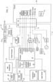
- Fig. 3 illustrates a block diagram of portable communication device 10.
- portable communication device 10 includes a memory 22 and a processor 24 coupled to memory 22 for executing programmed instructions.
- Processor 24 may include one or more processing units (e.g., in a multi-core configuration).
- Portable communication device 10 is programmable to perform one or more operations described herein by programming memory 22 and/or processor 24.
- processor 24 may be programmed by encoding an operation as executable instructions and providing the executable instructions in memory device 22.
- Processor 24 may include, but is not limited to, a general purpose central processing unit (CPU), a microcontroller, a reduced instruction set computer (RISC) processor, an open media application platform (OMAP), an application specific integrated circuit (ASIC), a programmable logic circuit (PLC), and/or any other circuit or processor capable of executing the functions described herein.
- the methods described herein may be encoded as executable instructions embodied in a computer-readable medium including, without limitation, a storage device and/or a memory device. Such instructions, when executed by processor 24, cause processor 24 to perform at least a portion of the functions described herein.
- the above examples are exemplary only, and thus are not intended to limit in any way the definition and/or meaning of the term processor.
- processor 24 includes a number of communication interfaces, such as universal serial bus (USB) interface, display serial interface (DSI), an HDQ interface (master/slave), a serial peripheral interface bus (SPI) interface, an I 2 C bus, a universal asynchronous receiver/transmitter (UART) interface, a micro-USB interface, an HDMI interface, and several general purpose input/outputs (GPlas).
- USB interface from processor 24 utilizes a USC physical layer circuit (PHY IC) controller 54 to provide a full USB interface to USB 1.0, 2.0, 3.0 or other versions of USB compliant modules.
- PHY IC physical layer circuit
- DSI interface is compliant with MIPI DSI 1.0 standard or other standards of display communication protocols. It should be appreciated that the number, the type and/or the standard of communication interfaces provided from processor 24 may be different in other portable communication device embodiments.
- Memory 22 is one or more devices that enable information such as executable instructions and/or other data to be stored and retrieved.
- Memory 22 may include one or more computer-readable media, such as, without limitation, dynamic random access memory (DRAM), static random access memory (SRAM), a solid state disk, and/or a hard disk.
- Memory 22 may be configured to store, without limitation, executable instructions, operating systems, applications, resources, installation scripts and/or any other type of data suitable for use with the methods and systems described herein.
- Non-transitory memory 22 Instructions for operating systems and applications are located in a functional form on non-transitory memory 22 for execution by processor 24 to perform one or more of the processes described herein.
- These instructions in the different embodiments may be embodied on different physical or tangible computer-readable media, such as memory 22 or another memory, such as a computer-readable media 26, which may include, without limitation, a flash drive, thumb drive, etc.
- instructions are located in a functional form on non-transitory computer-readable media 26, which may include, without limitation, smart-media (SM) memory, compact flash (CF) memory, secure digital (SD) memory, memory stick (MS) memory, multimedia card (MMC) memory, and micro-drive memory, etc.
- Computer-readable media 26 is selectively insertable and/or removable from portable communication device 10 to permit access and/or execution by processor 24. In some embodiments, computer-readable media 26 is not removable.
- portable communication device 10 includes an interface connector 28 coupled to processor 24.
- interface connector 28 provides a single, dedicated connector for providing communication between processor 24 and a module coupled to interface connector 28.
- a module 100 may access one or more of the communication interfaces provided by processor 24 to communicate with processor 24 through different communication protocols, such as, for example, USB, DSI, I 2 C, SPI, UART, etc.
- processor 24 provides HDQ (master/slave) interface for detection, interrogation, and authentication of the module. More specifically, in the exemplary embodiment, HDQ interface provides a single-wire protocol for communication between the HDQ master processor 24 and a HDQ slave device, such as module 100. Further, processor 24 provides a device power connection to module 100, which processor 24 utilizes to detect whether or not module 100 includes one or more batteries. Moreover, interface connector 28 provides access to multiple GPIOs from processor 24, which may be programmed by processor 24 to perform one or more processes depending on the type of module coupled thereto. For example, one of the GPIOs provides a detect connection, such that processor 24 is able to detect coupling of module 100 to interface connector 28.
- interface connector 28 provides numerous communication channels between processor 24 and a module coupled to interface connector 28 to support a variety of communication protocols, alone or simultaneously. As should be apparent, however, interface connector 28 may provide one or more different communication channels between processor 24 and various other modules in other portable communication device embodiments.
- portable communication device 10 includes a GPS component 30, which is configured to provide location data to processor 24.
- the location data permits processor 24 to determine the location of portable communication device 10 and/or provide functionality dependent on the location of portable communication device 10, such as, for example, navigation functionality.
- portable communication device 10 includes a crypto-processor 32, which is configured to encrypt at least a portion of data accessed by processor 24 for communication to/from portable communication device 10 and/or storage therein. Accordingly, some data may be segregated from other applications and/or operations of the portable communication device 10, and kept at a higher level of security than such applications/operations.
- GPS component 30 and crypto-processor 32 are disposed within housing 12, such that when back panel 20 is removed, GPS component 30 and crypto-processor 32 remain within housing 12 and coupled to processor 24.
- portable communication device 10 further includes a cellular controller 31 coupled to processor 24.
- Cellular controller 31 permits portable communication device 10 to communicate with a cellular network (not shown) to provide voice and/or data communication with the cellular network.
- portable communication device 10 includes two subscriber identity module (SIM) card sockets 33A and 33B coupled to cellular controller 31.
- SIM subscriber identity module
- portable communication device 10 is capable of receiving two SIM cards associated with two different cellular accounts, selectable by a user of portable communication device 10.
- portable communication device 10 is configured to access a personal cellular account and a business cellular account, allowing user to select therebetween to separate personal and business usage. It should be appreciated that a different number of SIM card sockets may be included in other embodiments.
- portable communication device 10 includes a USB controller 35 coupled to processor 24. As shown in Figure 3 , USB controller 35 is accessible through connector 37, which is separate from interface connector 28. In this manner, one or more different devices may communicate with portable communication device 10, but not coupled to housing 12 consistent with module 100. Similarly, in the exemplary embodiment, portable communication device 10 further includes a high-definition multimedia interface (HDMI) controller 2 coupled to processor 24 and accessible through a connector 41, separate from interface connector 28. In at least one embodiment, connectors 37 and/or 41 may provide micro-USB and/or micro-HDMI connections to portable communication device 10.
- HDMI high-definition multimedia interface
- portable communication device 10 may include one or more of a Bluetooth controller, a ZigBee controller, a Wi-Fi controller, etc. to provide one or more wireless communication channel separate from interface connector 28. While GPS component 30, crypto processor 32 and cellular controller 31 are provided at least partially in hardware, it should be further appreciated that one or more components integrated into portable communication device 10 may be provided through software and/or firmware associated with processor 24. In one example, processor 24 provides an air interface firewall, configured to analyze low-level air interface protocols of portable communication device 10 and permit or deny network transmissions based on approved network identities and characteristics.
- air interface protocol data from cellular controller 31 containing cellular network identities and characteristics is provided to processor 24 and analyzed by processor 24 to determine if portable communication device 10 should be permitted to conduct network transmissions via cellular networks identified by cellular controller 31.
- the level of analysis provided adds network security to portable communication device 10 by having processor 24 further authenticate the network connections of cellular controller 31 beyond using standard cellular network protocol authentication mechanisms of cellular controller 31 by themselves.
- other air interface components of portable communication device 10 such as, for example a Bluetooth controller, Wi-Fi controller, etc., may also be monitored by the air interface firewall.
- portable communication device embodiments may includes more or fewer components integrated with or external to processor 24 and usable separate from interface connector 28. Further, it should be appreciated that one or more components included in portable communication device 10 may interact with module 100 to provide a particular function. Still further, one or more components included in portable communication device 10 may be disabled, permitting processor 24 to utilize similar components within module 100.
- portable communication device 10 is configured to communicate with multiple different types of modules 100.
- Each different one of modules 100 generally provide accessory functionality to portable communication device 10, through addition of processing, memory, communication, and/or power functionality.
- portable communication device 10 may provide accessory functionality through multiple different communication channels.
- processor 24 and interface connector 28 provide several communication interfaces, from which module 100 is permitted to select. While exemplary module 100 utilizes each of the communication interfaces from processor 24, it should be appreciated that a module consistent with the present disclosure may utilize less than all communication interfaces available from processor 24.
- a Pico projector module 100 may utilize only a display interface and/or a USB interface, along with the detect and/or the HDQ interfaces.
- Modules 100 may be designed and/or provided to select among several communication protocols available from portable communication device 10. Accordingly, modules 100 may communicate with processor 24 according to a preferred communication protocol, such as USB, SPI, I 2 C, UART, etc., based on an efficient communication channel between module 100 and processor 24, and not based on conforming module 100 to a single communication protocol available for known devices. In this manner, portable communication device 10 provides a substantially universal embodiment, by inclusion of interface connector 28.
- a preferred communication protocol such as USB, SPI, I 2 C, UART, etc.
- module 100 may include, without limitation, additional displays (e.g., large touch screens, pico projectors, etc.), sensors (e.g., health, nuclear, chemical, biological, etc.), radios (e.g., cellular radio, satellite radio, military radio, etc.), external power sources (e.g., extended batteries, solar power, chemical power, biological power, etc.), readers (e.g., biometrics, barcodes, radio frequency identifications (RFIDs), smart cards, etc.), enhanced positioning hardware (e.g., enhanced GPS, inertial navigation systems, etc.), auxiliary processors/memory and an encryption module (e.g., used with crypto processor 32 or in place of crypto processor 32, etc.) to provide one or more accessory functions.
- additional displays e.g., large touch screens, pico projectors, etc.
- sensors e.g., health, nuclear, chemical, biological, etc.
- radios e.g., cellular radio, satellite radio, military radio, etc.
- external power sources
- processor 24 detects the presence of the module through a detection connection of interface connector 28, as illustrated in Fig. 3 .
- the detection connection may pull, for example, an input of processor 24 to a logically high or low state to indicate a module is coupled thereto.
- processor 24 may detect module 100 through use of one or more mechanical devices, such as a contact switch. When module 100 is detected, processor 24 interrogates module 100 for the module's identity to determine if module 100 is an approved module.
- the identity of module 100 includes a numerical and/or alpha-numerical code, indicating manufacturer of module 100, a type of module 100, the unique serial number for module 100, and communication interfaces utilized by module 100. It should be understood that different information may be conveyed by the identity of a module suitable to couple to portable communication device 10.
- portable communication device 10 may restrict the modules usable therewith, by permitting only vendor approved modules to be utilized with portable communication device 10.
- portable communication device 10 may include, stored in memory 22 and/or stored remotely and accessible by portable communication device 10 (e.g., via a wireless network, etc.), a list of identifies of modules approved for use with portable communication device 10. Based on the list of identifies and the identity of module 100, processor 24 is able to authenticate module 100. If module 100 is not approved, portable communication device 10 may halt and/or limit further communication with module 100.
- processor 24 is configured to communicate with module 100. More specifically, by knowing the identity of the module, processor 24 is able to determine one or more communication protocols usable with the module. In one example, upon identifying the module as enhanced sized touch screen display (as compared to touch screen 18), processor 24 enables DSI, SPI, I 2 C, GPIOs and/or power interfaces to enable module 100 to communicate therewith. In other examples, different modules 100 may dictate one or more different communication protocols, which are each supported by portable communication device 10.
- portable communication device 10 and module 100 communicate as necessary to permit processor 24 to utilize the accessory function provided by module 100.
- Communication channels therebetween are established by powering components associated with interface connector 28.
- processor 24 is configured to disable power associated with USB communication channel, when USB communication channel is not selected for communication with module 100. Such disabled power may include, for example, powering down USB controller 54 associated with the USB interface.
- processor 24 may selectively enable one type of communication protocol over another communication protocol, using a shared communication channel. Specifically, as shown in Fig. 3 , SPI communication and UART communication at least partially share a communication channel from processor 24. When module 100 is detected and one of these communication protocols is required, processor 24 alternately selects between SPI communication and UART communication as necessary to communicate with module 100.
- a switch 52 is provided and controlled by a GPIO of processor 24 to selectively provide one of the SPI and UART communication interfaces. Switch 52 is a single-pull-double-throw (SPDT) switch in this particular example.
- SPI and UART interfaces are suitable to be alternately provided because each provides the same logic level with the same number of inputs/outputs.
- other communication interfaces and/or protocols may share one or more communication channels between processor 24 and module 100, potentially dependent on the similarities among the communication interfaces and/or protocols.
- processor 24 determines if module 100 includes a module battery 102 through the device power connection.
- portable communication device 10 includes a battery 38 to power processor 24 and/or other components of portable communication device 10.
- Module battery 102 may be utilized to supplement power to portable communication device 10.
- processor 24 determines if module 100 includes module battery 102. If not, processor 24 controls switch 40 to provide power to and/or charge module 100.
- switch 40 includes a SPDT switch.
- processor 24 toggles switch 40 to power and/or charge portable communication device 10 from module battery 102. In this manner, the life of battery 38 and/or battery 102 may be extended, through bi-directional charging between batter 38 and battery 102. In other embodiments, processor 24 may continue to power portable communication device 10 from battery 38, even when module battery 102 is detected.
- processor 24 may provide a section for presentation to a user, such that the user is permitted to select one of batteries 38 and 102 to power portable communication device 10 through an input to input device 16. Additionally, or alternatively, the user may select a direction of charge to determine which of batteries 28 and 102 is charged from the other. In at least on embodiment, battery 38 may be charged from module battery 102 of module 100. Further, when portable communication device 10 is powered from module battery 102, processor 24 may utilize an eject sequence to ensure power is uninterrupted to portable communication device 10 when module 100 in removed. In such an embodiment, processor 24 may provide an eject sequence to presentation device 14 to solicit user inputs to engage battery 38, prior to ejecting module 100.
- processor 24 is configured to manage power at said interface connector to permit hot-swap of module 100. More specifically, in the exemplary embodiment, at least one of the GPIOs of processor 24 is coupled to a module insertion connection of interface connector 28 and configured as to provide an interrupt to processor 24, when module 100 is coupled to interface connector 28. In response, processor 24 interrogates module 100 via the HDQ interface to read the identification of module 100 and determine if module 100 is an approved module. If module 100 is approved, processor enables communication interface(s) and/or power at interface connector 28 to permit and/or initiate communication between portable communication device 10 and module 100.
- processor 24, through interface connector 28, provides a clock (CLK) connection 58 to module 100.
- CLK connection 58 may be used by module 100 to synchronize communication and/or data transfer between processor 24 and module 100.
- CLK connection 58 may be understood by module 100 to indicate the time and /or size of data to be transmitted to processor 24.
- processor 24 utilizes CLK connection 58 to determine what type of data it is receiving from module 100. It should be appreciated that portable communication device 10 and/or module 100 may include various other methods for synchronizing data transfer therebetween.
- CLK connection 58 includes a buffer 56 configured to enable or disable the CLK signal output to interface connector 28.
- module 100 may include a variety of different form-factors and couple to housing 12 in a variety of manners.
- module 100 is coupled to portable communication device 10 in place of back panel 20.
- the cross-section of module 100 is substantially consistent with the cross-section of housing 12, thereby providing module 100 within substantially the same form-factor as portable communication device 10 and forming a substantially integral unit with housing 12 when coupled thereto.
- Other configurations e.g., shapes, sizes, cross-sectional areas, etc.
- modules 100 may be included in other portable communication device embodiments.
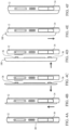
- Fig. 4 illustrates removal of back panel 20 and addition of module 100.
- latching mechanisms 34 on either side of housing 12 are depressed to disengage latching mechanisms 34 from back panel 20.
- Back panel 20 then is slid relative to housing 12 ( Fig. 4B ) to disengage mounting tabs 36 of back panel 20 from corresponding parts of housing 12 and latching mechanisms 34.
- back panel 20 is separated from housing 12 ( Fig. 4C ). Accordingly, the sequence from Fig. 4A to Fig, 4C provides a portable communication device 10 with the back panel 20 removed, as shown in Fig. 5 .
- module 100 In order to couple module 100 to housing 12, module 100 is disposed proximate to housing 12 ( Fig. 4D ) and brought into contact with housing 12 ( Fig. 4E ) to engage mounting tabs 26 with complementary structures of housing 12.
- mounting tabs 36 of module 100 When in contact with housing 12, as shown in Fig. 4E , mounting tabs 36 of module 100 are aligned with corresponding features of housing 12 and latching mechanisms 34.
- latching mechanisms 34 engage mounting tabs 36 to retain module 100 relative to housing 12 ( Fig. 4F ).
- module 100 and housing 12 are shown in Figs. 4A-F for purposes of illustration, it should be appreciated that various different types of engagement between module 100 and housing 12 may be utilized in other portable communication device embodiments.
- Fig. 5 illustrates portable communication device 10 with back panel 20 removed, but no module 100 added.
- interface connector 28 is accessible from the back side of housing 12. Accordingly, the sliding engagement of module 100 and housing 12, described with reference to Fig. 4 , provides engagement of interface connector 28 with a mating connector of module 100. In this manner, module 100 electrically couples with processor 24, as shown in Fig. 3 .
- interface connector 28 is structured to provide a high mating cycle connector, which permits modules 100 to be repeatedly coupled and decoupled from interface connector 28 without substantially degrading the connection therebetween.
- interface connector 28 includes pins tapered at its tip and provides right-angle actuation to mate complimentary module connector 29, as shown in Figs. 7-8 .
- interface connector 28 is through-hole mounted to a printed circuit board (PCB) (not shown) within housing 12.
- PCB printed circuit board
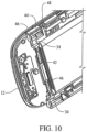
- portable communication device 10 includes latching mechanisms 34 disposed on opposite sides of housing 12.
- each latching mechanism 34 is biased toward an outer edge of housing 12, by a biasing member 42.
- biasing member 42 is a spring extending about a portion of latching mechanism 34.
- a mating connector of module 100 initially engages interface connector 28.
- a void 50 exists above interface connector 28, which permits complimentary module connector 29 of module 100 to be positioned proximate to interface connector 28 for sliding engagement therewith.
- biasing member 42 biases latching member 34 towards the outer edge of housing 12, thereby causing mounting tab 36 to come to rest in recess 46 of latching mechanism 34.
- interface connector 28 is fully engaged in the mating connector of module 100, to provide communication therebetween.
- protuberance 48 defining first surface 44 retains the mounting tab 36 (shown in Fig. 9 ) and prevents sliding movement of module 100 relative to housing 12.
- each latching mechanism 34 is depressed inward, against the force of biasing member 42 to permit mounting tabs 36 to slide past protuberance 48, along first surface 44 of protuberance 48.
- Module 100 may then be sufficiently slid, as shown in Fig. 4 , to disengage mounting tabs 36 and position the mating connector thereof within void 50, such that module 100 may be removed from housing 12 and interface connector 28.
- Other mounting tabs 36 of module 100 and/or housing 12 are structured to inhibit other relative movement between module 100 and housing 12.
- module 100 may be snap engaged with housing 12 to provide such a connection.
- technical effects of the methods, systems, and computer-readable media described herein include at least one of: (a) detecting the presence of a module coupled to the interface connector of the portable communication device, (b) identifying the module, and (c) selecting one of a plurality of communication protocols supported by the portable communication device to communicate through the interface connector with the module, based on the identity of the module.
- One or more aspects of the present disclosure transform a general-purpose computing device into a special-purpose computing device when configured to execute the instructions described herein.
Description
- The field of the disclosure relates generally to portable communication devices and related methods, and more particularly, to portable communication device with modules providing one or more accessory functions.
- Recently, portable and ultra-portable communication devices, such as smartphones, cellular phones, personal digital assistants (PDAs), etc., have grown in use and popularity among a variety of different types of users. As the market has progressed, more and more functionality has been incorporated into portable communication devices. More generally, as the number of different types of portable communication devices increases, the functionality included therein, as well as the demand for added functionality, also increases. Manufacturers of portable communication devices have responded to the increased demand for functionality by incorporating some additional functionality and opening the relevant operating systems to permit third parties to develop additional functionality.
As the functionality of the portable communication devices increases through effort of manufacturers and/or third parties, the amount and/or type of data accessed, received by and/or transmitted from such devices has also increased. With the increased access to data and the open operating systems provided by manufacturers, security policies are often implemented at the portable communication devices to limit exposure of data accessed by the portable communication device. - European Patent Application Publication
EP2230605 A1 , in accordance with its abstract, describes various communication techniques for communication between a mobile computing device and an accessory. An accessory protocol that is generic to the mobile computing device can be used for some communication. An application executing at the mobile computing device can communicate with the accessory using an application communication protocol. In some examples, the application communication protocol can be different from the accessory communication protocol. In other examples the application protocol may only be recognized by the application and the accessory. In some examples, messages conforming to an application protocol can be communicated between the application and the accessory by packaging the messages inside a message conforming to the accessory communication protocol. - United States Patent Application Publication
US 2010/277415 A1 , in accordance with its abstract, describes a mobile communication device includes a touch screen device, and a multimedia module that moveably connects to the touch screen device. The multimedia module includes a first input or output mechanism provided at a first location of the multimedia module that is below the touch screen device. The first input or output mechanism is moveable from the first location to above a first end portion of the touch screen device. The multimedia module also includes a second input or output mechanism provided at a second location of the multimedia module that is below the touch screen device. The second input or output mechanism is moveable from the second location to above a second end portion of the touch screen device. - German Utility Model
DE 20009217 U1 , in accordance with its description, describes a battery pack for mobile phones, in particular to a battery pack with removable mounting plate for SIM cards, on which at least two SIM cards are arranged.
United States Patent Application PublicationUS2010/093401 A1 , in accordance with its abstract, describes a wireless communicator including a housing, wireless communication functionality located within the housing, native user interface functionality cooperating with the wireless communication functionality and including user interface surfaces located on at least one outer facing surface of the housing, and pouching responsive electrical interconnection functionality responsive to pouching orientation of the housing in a pouch of an enhanced function device for automatically causing the wireless communication functionality to adapt to interoperation with parenting user interface functionality forming part of the enhanced function device at least partially instead of with the native user interface functionality. - United States Patent Application Publication
US2007/099593 A1 , in accordance with its abstract, describes a portable communication device and system in accordance with the exemplary embodiment comprises interchangeable accessory modules allowing different accessory devices to be used with a portable communication device assembly. The accessory modules and the portable communication device assembly form portable communication devices when the accessory modules are secured to the portable communication device assembly. The accessory devices may include sensing devices, music players, displays, GPS receivers, user interfaces, cameras, memory devices, as well as others devices. The portable communication device manages and controls the interchangeable accessory modules by exchanging data and control signals through a connection interface. - A portable communication device for use in supporting voice and/or data communication, said portable communication device comprising: a housing; a device battery (38) disposed within said housing; a processor disposed at least partially within said housing; and an interface connector disposed at said housing and coupled to said processor, said interface connector configured to couple to a module (100); the portable communication device further comprising a back panel removably coupled to said housing such that the module is coupleable to said portable communication device in place of said
back panel when said back panel is uncoupled from said housing, said module configured to provide at least one accessory function, wherein said processor is configured to communicate, through said interface connector, via a plurality of communication protocols and to select at least one of the plurality of communication protocols based on the module coupled to said interface connector and wherein the processor is further configured to: determine if the module includes at least one battery, and when the at least one battery is included, present to the user a section to permit the user to select one of the device battery and the at least one battery of the module to power the portable communication device. - A method for use in appending at least one accessory function to a portable communication device, the portable communication device including a housing, a device battery disposed within said housing, a back panel removably coupleable to said housing, a processor and an interface connector, said method comprising: detecting the presence of a module coupled to the interface connector of the portable communication device, wherein the module is coupled to the housing of the portable communication device in place of said back panel; identifying, at the processor, the module; and selecting, at the processor, at least one of a plurality of communication protocols supported by the portable communication device to communicate through the interface connector with the module, based on the identity of the module; and determining if the module includes at least one battery, and presenting to the user a section to permit the user to select the at least one battery of the module to power the portable communication device when included, and monitoring a power level of the at least one battery.
- In an example, a portable communication device for use in supporting voice and/or data communication is provided. The portable communication device includes a housing, an interface connector disposed at least partially within the housing, a processor disposed within the housing and coupled to the interface connector, and a module coupled to the housing and the interface connector. The module is configured to provide at least one accessory function. The processor is configured to communicate with the module according to a plurality of communication protocols through an interface connector. The processor is configured to identify the module and communicate with the module, based on the identity of the module, according to at least one of the plurality of communication protocols.
- Advantageously, the processor is further configured to control power through said interface connector to enable hot-swap of said module with another module.
- Advantageously, the portable communication device further includes a crypto processor coupled to the processor and configured to encrypt at least a portion of data accessed by the processor.
- Advantageously, the module comprises at least one of an additional display, a radio, a reader, an enhanced positioning hardware, an auxiliary processor, or an encryption module to provide the accessory function.
- Advantageously, the portable communication device further comprises a battery disposed within said housing, the module including a module battery, and the processor is configured to provide bi-directional charging between said battery and the module battery.
- The features, functions, and advantages that have been discussed can be achieved independently in various embodiments or may be combined in yet other embodiments, further details of which can be seen with reference to the following description and drawings.
-
-
Fig. 1 is a front perspective view of a portable communication device according to one example embodiment of the present disclosure. -
Fig. 2 is a back perspective view of the portable communication device ofFig. 1 . -
Fig. 3 is a block diagram of the portable communication device ofFig. 1 . -
Figs. 4A-F illustrate a sliding engagement of the portable communication device ofFig. 1 with a module. -
Fig. 5 is a back view of the portable communication device ofFig. 1 , with the back panel omitted. -
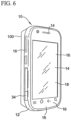
Fig. 6 is a perspective view of the portable communication device ofFig. 1 , with a module coupled thereto. -
Fig. 7 is a front perspective view of an exemplary interface connector. -
Fig. 8 is a back perspective view of the interface connector ofFig. 7 . -
Fig. 9 is a partially exploded view of the portable communication device ofFig. 1 . -
Fig. 10 is a sectional view of a partially disassembled back of the portable communication device ofFig. 1 . - The subject matter described herein relates generally to appending one or more accessory functions to a portable communication device by coupling a module to the portable communication device through an interface connector.
-
Figs 1 and 2 illustrate an exemplaryportable communication device 10. In the exemplary embodiment,portable communication device 10 is provided for supporting voice communication with another device, such as another portable communication device. Moreover,portable communication device 10 may include a variety of other functionalities, including network access, SMS messaging, hosting of one or more applications, data processing, encryption, and/or other functions, etc. In this exemplary embodiment,portable communication device 10 is a smartphone, configured to communicate through one or more cellular networks. - As shown,
portable communication device 10 includes ahousing 12 andmultiple presentation devices 14 disposed at least partially withinhousing 12.Presentation device 14 outputs information such as, but not limited to, data related to operation ofportable communication device 10, commands, requested data, messages, one or more input devices (such as, a virtual keyboard), and/or any other type of data to a user. In several examples,presentation device 14 may include, for example, a liquid crystal display (LCD), a light-emitting diode (LED) display, a light-emitting diode (LED), a camera flash, an organic LED (OLED) display, and/or an "electronic ink" display. In some embodiments,multiple presentation devices 14 may be included to present data to a user visually and/or audibly. In this exemplary embodiment,presentation device 14 includes an audio output for use in voice communication. - In the exemplary embodiment,
portable communication device 10 further includesmultiple input devices 16 disposed at least partially withinhousing 12. Eachinput device 16 may be configured to receive selections, requests, commands, information, data, and/or any other type of inputs, according to one or more of the methods and/or processes described herein.Input devices 16 may include, for example, buttons, a keyboard, a microphone, a vibrator, a pointing device, a stylus, a touch sensitive panel (e.g., a touch pad or a touch screen), a gyroscope, an accelerometer, a digital compass, a position detector, a camera, a second camera, and/or an audio input interface. In the exemplary embodiment, a single component, such as atouch screen 18, functions as bothpresentation device 14 andinput device 16. - In the exemplary embodiment,
portable communication device 10 includes backpanel 20, which is engaged tohousing 12.Back panel 20 defines a cross-section substantially consistent withhousing 12, thereby forming a substantially integral unit withhousing 12 when coupled thereto.Back panel 20 is removable from the back side ofportable communication device 10 to provide access to one or more aspects ofportable communication device 10, including an interface connector discussed below. -
Fig. 3 illustrates a block diagram ofportable communication device 10. In the exemplary embodiment,portable communication device 10 includes amemory 22 and aprocessor 24 coupled tomemory 22 for executing programmed instructions.Processor 24 may include one or more processing units (e.g., in a multi-core configuration).Portable communication device 10 is programmable to perform one or more operations described herein byprogramming memory 22 and/orprocessor 24. For example,processor 24 may be programmed by encoding an operation as executable instructions and providing the executable instructions inmemory device 22. -
Processor 24 may include, but is not limited to, a general purpose central processing unit (CPU), a microcontroller, a reduced instruction set computer (RISC) processor, an open media application platform (OMAP), an application specific integrated circuit (ASIC), a programmable logic circuit (PLC), and/or any other circuit or processor capable of executing the functions described herein. The methods described herein may be encoded as executable instructions embodied in a computer-readable medium including, without limitation, a storage device and/or a memory device. Such instructions, when executed byprocessor 24,cause processor 24 to perform at least a portion of the functions described herein. The above examples are exemplary only, and thus are not intended to limit in any way the definition and/or meaning of the term processor. - As shown,
processor 24 includes a number of communication interfaces, such as universal serial bus (USB) interface, display serial interface (DSI), an HDQ interface (master/slave), a serial peripheral interface bus (SPI) interface, an I2C bus, a universal asynchronous receiver/transmitter (UART) interface, a micro-USB interface, an HDMI interface, and several general purpose input/outputs (GPlas). In the exemplary embodiment, USB interface fromprocessor 24 utilizes a USC physical layer circuit (PHY IC)controller 54 to provide a full USB interface to USB 1.0, 2.0, 3.0 or other versions of USB compliant modules. Additionally, DSI interface is compliant with MIPI DSI 1.0 standard or other standards of display communication protocols. It should be appreciated that the number, the type and/or the standard of communication interfaces provided fromprocessor 24 may be different in other portable communication device embodiments. -
Memory 22, as described herein, is one or more devices that enable information such as executable instructions and/or other data to be stored and retrieved.Memory 22 may include one or more computer-readable media, such as, without limitation, dynamic random access memory (DRAM), static random access memory (SRAM), a solid state disk, and/or a hard disk.Memory 22 may be configured to store, without limitation, executable instructions, operating systems, applications, resources, installation scripts and/or any other type of data suitable for use with the methods and systems described herein. - Instructions for operating systems and applications are located in a functional form on
non-transitory memory 22 for execution byprocessor 24 to perform one or more of the processes described herein. These instructions in the different embodiments may be embodied on different physical or tangible computer-readable media, such asmemory 22 or another memory, such as a computer-readable media 26, which may include, without limitation, a flash drive, thumb drive, etc. Further, instructions are located in a functional form on non-transitory computer-readable media 26, which may include, without limitation, smart-media (SM) memory, compact flash (CF) memory, secure digital (SD) memory, memory stick (MS) memory, multimedia card (MMC) memory, and micro-drive memory, etc. Computer-readable media 26 is selectively insertable and/or removable fromportable communication device 10 to permit access and/or execution byprocessor 24. In some embodiments, computer-readable media 26 is not removable. - Further, as shown,
portable communication device 10 includes aninterface connector 28 coupled toprocessor 24. In the exemplary embodiment,interface connector 28 provides a single, dedicated connector for providing communication betweenprocessor 24 and a module coupled tointerface connector 28. Throughinterface connector 28, amodule 100 may access one or more of the communication interfaces provided byprocessor 24 to communicate withprocessor 24 through different communication protocols, such as, for example, USB, DSI, I2C, SPI, UART, etc. - Additionally, through
interface connector 28,processor 24 provides HDQ (master/slave) interface for detection, interrogation, and authentication of the module. More specifically, in the exemplary embodiment, HDQ interface provides a single-wire protocol for communication between theHDQ master processor 24 and a HDQ slave device, such asmodule 100. Further,processor 24 provides a device power connection tomodule 100, whichprocessor 24 utilizes to detect whether or notmodule 100 includes one or more batteries. Moreover,interface connector 28 provides access to multiple GPIOs fromprocessor 24, which may be programmed byprocessor 24 to perform one or more processes depending on the type of module coupled thereto. For example, one of the GPIOs provides a detect connection, such thatprocessor 24 is able to detect coupling ofmodule 100 to interfaceconnector 28. In the exemplary embodiment,interface connector 28 provides numerous communication channels betweenprocessor 24 and a module coupled tointerface connector 28 to support a variety of communication protocols, alone or simultaneously. As should be apparent, however,interface connector 28 may provide one or more different communication channels betweenprocessor 24 and various other modules in other portable communication device embodiments. - Referring again to
Fig. 3 ,portable communication device 10 includes aGPS component 30, which is configured to provide location data toprocessor 24. The location data permitsprocessor 24 to determine the location ofportable communication device 10 and/or provide functionality dependent on the location ofportable communication device 10, such as, for example, navigation functionality. Moreover,portable communication device 10 includes a crypto-processor 32, which is configured to encrypt at least a portion of data accessed byprocessor 24 for communication to/fromportable communication device 10 and/or storage therein. Accordingly, some data may be segregated from other applications and/or operations of theportable communication device 10, and kept at a higher level of security than such applications/operations. In this particular embodiment,GPS component 30 and crypto-processor 32 are disposed withinhousing 12, such that whenback panel 20 is removed,GPS component 30 and crypto-processor 32 remain withinhousing 12 and coupled toprocessor 24. - In the exemplary embodiment,
portable communication device 10 further includes acellular controller 31 coupled toprocessor 24.Cellular controller 31 permitsportable communication device 10 to communicate with a cellular network (not shown) to provide voice and/or data communication with the cellular network. In this example,portable communication device 10 includes two subscriber identity module (SIM)card sockets cellular controller 31. In this manner,portable communication device 10 is capable of receiving two SIM cards associated with two different cellular accounts, selectable by a user ofportable communication device 10. Specifically, in one example,portable communication device 10 is configured to access a personal cellular account and a business cellular account, allowing user to select therebetween to separate personal and business usage. It should be appreciated that a different number of SIM card sockets may be included in other embodiments. - Further,
portable communication device 10 includes aUSB controller 35 coupled toprocessor 24. As shown inFigure 3 ,USB controller 35 is accessible throughconnector 37, which is separate frominterface connector 28. In this manner, one or more different devices may communicate withportable communication device 10, but not coupled tohousing 12 consistent withmodule 100. Similarly, in the exemplary embodiment,portable communication device 10 further includes a high-definition multimedia interface (HDMI) controller 2 coupled toprocessor 24 and accessible through aconnector 41, separate frominterface connector 28. In at least one embodiment,connectors 37 and/or 41 may provide micro-USB and/or micro-HDMI connections toportable communication device 10. - Additionally, or alternatively,
portable communication device 10 may include one or more of a Bluetooth controller, a ZigBee controller, a Wi-Fi controller, etc. to provide one or more wireless communication channel separate frominterface connector 28. WhileGPS component 30,crypto processor 32 andcellular controller 31 are provided at least partially in hardware, it should be further appreciated that one or more components integrated intoportable communication device 10 may be provided through software and/or firmware associated withprocessor 24. In one example,processor 24 provides an air interface firewall, configured to analyze low-level air interface protocols ofportable communication device 10 and permit or deny network transmissions based on approved network identities and characteristics. In this example, air interface protocol data fromcellular controller 31 containing cellular network identities and characteristics is provided toprocessor 24 and analyzed byprocessor 24 to determine ifportable communication device 10 should be permitted to conduct network transmissions via cellular networks identified bycellular controller 31. In this example, the level of analysis provided adds network security toportable communication device 10 by havingprocessor 24 further authenticate the network connections ofcellular controller 31 beyond using standard cellular network protocol authentication mechanisms ofcellular controller 31 by themselves. It should be noted that other air interface components ofportable communication device 10, such as, for example a Bluetooth controller, Wi-Fi controller, etc., may also be monitored by the air interface firewall. - It should be appreciated that other portable communication device embodiments may includes more or fewer components integrated with or external to
processor 24 and usable separate frominterface connector 28. Further, it should be appreciated that one or more components included inportable communication device 10 may interact withmodule 100 to provide a particular function. Still further, one or more components included inportable communication device 10 may be disabled, permittingprocessor 24 to utilize similar components withinmodule 100. - In the exemplary embodiment, through
interface connector 28,portable communication device 10 is configured to communicate with multiple different types ofmodules 100. Each different one ofmodules 100 generally provide accessory functionality toportable communication device 10, through addition of processing, memory, communication, and/or power functionality. In the exemplary embodiment,portable communication device 10 may provide accessory functionality through multiple different communication channels. Specifically,processor 24 andinterface connector 28 provide several communication interfaces, from whichmodule 100 is permitted to select. Whileexemplary module 100 utilizes each of the communication interfaces fromprocessor 24, it should be appreciated that a module consistent with the present disclosure may utilize less than all communication interfaces available fromprocessor 24. For example, aPico projector module 100 may utilize only a display interface and/or a USB interface, along with the detect and/or the HDQ interfaces. -
Modules 100 may be designed and/or provided to select among several communication protocols available fromportable communication device 10. Accordingly,modules 100 may communicate withprocessor 24 according to a preferred communication protocol, such as USB, SPI, I2C, UART, etc., based on an efficient communication channel betweenmodule 100 andprocessor 24, and not based on conformingmodule 100 to a single communication protocol available for known devices. In this manner,portable communication device 10 provides a substantially universal embodiment, by inclusion ofinterface connector 28. - It should be appreciated that various different types of
modules 100 may be used with theportable communication device 10. For example,module 100 may include, without limitation, additional displays (e.g., large touch screens, pico projectors, etc.), sensors (e.g., health, nuclear, chemical, biological, etc.), radios (e.g., cellular radio, satellite radio, military radio, etc.), external power sources (e.g., extended batteries, solar power, chemical power, biological power, etc.), readers (e.g., biometrics, barcodes, radio frequency identifications (RFIDs), smart cards, etc.), enhanced positioning hardware (e.g., enhanced GPS, inertial navigation systems, etc.), auxiliary processors/memory and an encryption module (e.g., used withcrypto processor 32 or in place ofcrypto processor 32, etc.) to provide one or more accessory functions. It should be appreciated that the modules listed herein are exemplary and not intended to limit the type and/or accessory function(s) provided bymodule 100. - During operation, when a module is coupled to
portable communication device 10,processor 24 detects the presence of the module through a detection connection ofinterface connector 28, as illustrated inFig. 3 . The detection connection may pull, for example, an input ofprocessor 24 to a logically high or low state to indicate a module is coupled thereto. In at least one other embodiment,processor 24 may detectmodule 100 through use of one or more mechanical devices, such as a contact switch. Whenmodule 100 is detected,processor 24 interrogatesmodule 100 for the module's identity to determine ifmodule 100 is an approved module. Specifically, in the exemplary embodiment, the identity ofmodule 100 includes a numerical and/or alpha-numerical code, indicating manufacturer ofmodule 100, a type ofmodule 100, the unique serial number formodule 100, and communication interfaces utilized bymodule 100. It should be understood that different information may be conveyed by the identity of a module suitable to couple toportable communication device 10. - In the exemplary embodiments, various different types of modules along the lines of
module 100 may be used withportable communication device 10. In various embodiments,portable communication device 10 may restrict the modules usable therewith, by permitting only vendor approved modules to be utilized withportable communication device 10. As such,portable communication device 10 may include, stored inmemory 22 and/or stored remotely and accessible by portable communication device 10 (e.g., via a wireless network, etc.), a list of identifies of modules approved for use withportable communication device 10. Based on the list of identifies and the identity ofmodule 100,processor 24 is able to authenticatemodule 100. Ifmodule 100 is not approved,portable communication device 10 may halt and/or limit further communication withmodule 100. - Conversely, if
module 100 is approved,processor 24 is configured to communicate withmodule 100. More specifically, by knowing the identity of the module,processor 24 is able to determine one or more communication protocols usable with the module. In one example, upon identifying the module as enhanced sized touch screen display (as compared to touch screen 18),processor 24 enables DSI, SPI, I2C, GPIOs and/or power interfaces to enablemodule 100 to communicate therewith. In other examples,different modules 100 may dictate one or more different communication protocols, which are each supported byportable communication device 10. - Upon establishing one or more communication channels therebetween,
portable communication device 10 andmodule 100 communicate as necessary to permitprocessor 24 to utilize the accessory function provided bymodule 100. Communication channels therebetween are established by powering components associated withinterface connector 28. For example,processor 24 is configured to disable power associated with USB communication channel, when USB communication channel is not selected for communication withmodule 100. Such disabled power may include, for example, powering downUSB controller 54 associated with the USB interface. - Additionally,
processor 24 may selectively enable one type of communication protocol over another communication protocol, using a shared communication channel. Specifically, as shown inFig. 3 , SPI communication and UART communication at least partially share a communication channel fromprocessor 24. Whenmodule 100 is detected and one of these communication protocols is required,processor 24 alternately selects between SPI communication and UART communication as necessary to communicate withmodule 100. In the exemplary embodiment, aswitch 52 is provided and controlled by a GPIO ofprocessor 24 to selectively provide one of the SPI and UART communication interfaces.Switch 52 is a single-pull-double-throw (SPDT) switch in this particular example. In the exemplary embodiment, SPI and UART interfaces are suitable to be alternately provided because each provides the same logic level with the same number of inputs/outputs. In various embodiments, other communication interfaces and/or protocols may share one or more communication channels betweenprocessor 24 andmodule 100, potentially dependent on the similarities among the communication interfaces and/or protocols. - In the exemplary embodiment, when
module 100 is detected,processor 24 determines ifmodule 100 includes amodule battery 102 through the device power connection. In various embodiments,portable communication device 10 includes abattery 38 topower processor 24 and/or other components ofportable communication device 10.Module battery 102 may be utilized to supplement power toportable communication device 10. Specifically, in the exemplary embodiment, whenportable communication device 10 detectsmodule 100,processor 24 determines ifmodule 100 includesmodule battery 102. If not,processor 24 controls switch 40 to provide power to and/orcharge module 100. In this example, switch 40 includes a SPDT switch. In contrast, ifmodule battery 102 is detected,processor 24 toggles switch 40 to power and/or chargeportable communication device 10 frommodule battery 102. In this manner, the life ofbattery 38 and/orbattery 102 may be extended, through bi-directional charging betweenbatter 38 andbattery 102. In other embodiments,processor 24 may continue to powerportable communication device 10 frombattery 38, even whenmodule battery 102 is detected. - Further, when
module battery 102 is detected,processor 24 may provide a section for presentation to a user, such that the user is permitted to select one ofbatteries portable communication device 10 through an input to inputdevice 16. Additionally, or alternatively, the user may select a direction of charge to determine which ofbatteries battery 38 may be charged frommodule battery 102 ofmodule 100. Further, whenportable communication device 10 is powered frommodule battery 102,processor 24 may utilize an eject sequence to ensure power is uninterrupted toportable communication device 10 whenmodule 100 in removed. In such an embodiment,processor 24 may provide an eject sequence topresentation device 14 to solicit user inputs to engagebattery 38, prior to ejectingmodule 100. - Further,
processor 24 is configured to manage power at said interface connector to permit hot-swap ofmodule 100. More specifically, in the exemplary embodiment, at least one of the GPIOs ofprocessor 24 is coupled to a module insertion connection ofinterface connector 28 and configured as to provide an interrupt toprocessor 24, whenmodule 100 is coupled tointerface connector 28. In response,processor 24 interrogatesmodule 100 via the HDQ interface to read the identification ofmodule 100 and determine ifmodule 100 is an approved module. Ifmodule 100 is approved, processor enables communication interface(s) and/or power atinterface connector 28 to permit and/or initiate communication betweenportable communication device 10 andmodule 100. - Additionally, in the exemplary embodiment,
processor 24, throughinterface connector 28, provides a clock (CLK)connection 58 tomodule 100.CLK connection 58 may be used bymodule 100 to synchronize communication and/or data transfer betweenprocessor 24 andmodule 100. Specifically, for example,CLK connection 58 may be understood bymodule 100 to indicate the time and /or size of data to be transmitted toprocessor 24. Likewise,processor 24 utilizesCLK connection 58 to determine what type of data it is receiving frommodule 100. It should be appreciated thatportable communication device 10 and/ormodule 100 may include various other methods for synchronizing data transfer therebetween. In the exemplary embodiment,CLK connection 58 includes abuffer 56 configured to enable or disable the CLK signal output to interfaceconnector 28. - It should be understood that
module 100 may include a variety of different form-factors and couple tohousing 12 in a variety of manners. In the exemplary embodiment,module 100 is coupled toportable communication device 10 in place ofback panel 20. In this manner (as shown inFig. 6 ), the cross-section ofmodule 100 is substantially consistent with the cross-section ofhousing 12, thereby providingmodule 100 within substantially the same form-factor asportable communication device 10 and forming a substantially integral unit withhousing 12 when coupled thereto. Other configurations (e.g., shapes, sizes, cross-sectional areas, etc.) ofmodules 100 may be included in other portable communication device embodiments. -
Fig. 4 illustrates removal ofback panel 20 and addition ofmodule 100. Specifically, from the assembled portable communication device 10 (Fig. 4A ), latchingmechanisms 34 on either side ofhousing 12 are depressed to disengage latchingmechanisms 34 fromback panel 20.Back panel 20 then is slid relative to housing 12 (Fig. 4B ) to disengage mountingtabs 36 ofback panel 20 from corresponding parts ofhousing 12 and latchingmechanisms 34. Once disengaged, backpanel 20 is separated from housing 12 (Fig. 4C ). Accordingly, the sequence fromFig. 4A to Fig, 4C provides aportable communication device 10 with theback panel 20 removed, as shown inFig. 5 . - In order to couple
module 100 tohousing 12,module 100 is disposed proximate to housing 12 (Fig. 4D ) and brought into contact with housing 12 (Fig. 4E ) to engage mountingtabs 26 with complementary structures ofhousing 12. When in contact withhousing 12, as shown inFig. 4E , mountingtabs 36 ofmodule 100 are aligned with corresponding features ofhousing 12 and latchingmechanisms 34. Upon sliding movement ofmodule 100, relative tohousing 12, latchingmechanisms 34 engage mountingtabs 36 to retainmodule 100 relative to housing 12 (Fig. 4F ). - Further detail of the engagement between
housing 12 andmodule 100 is described below with reference toFigs. 6-7 . - Furthermore, while sliding engagement of
module 100 andhousing 12 is shown inFigs. 4A-F is provided for purposes of illustration, it should be appreciated that various different types of engagement betweenmodule 100 andhousing 12 may be utilized in other portable communication device embodiments. -
Fig. 5 illustratesportable communication device 10 withback panel 20 removed, but nomodule 100 added. As shown, in the exemplary embodiment,interface connector 28 is accessible from the back side ofhousing 12. Accordingly, the sliding engagement ofmodule 100 andhousing 12, described with reference toFig. 4 , provides engagement ofinterface connector 28 with a mating connector ofmodule 100. In this manner,module 100 electrically couples withprocessor 24, as shown inFig. 3 . In the exemplary embodiment,interface connector 28 is structured to provide a high mating cycle connector, which permitsmodules 100 to be repeatedly coupled and decoupled frominterface connector 28 without substantially degrading the connection therebetween. Specifically, for example,interface connector 28 includes pins tapered at its tip and provides right-angle actuation to matecomplimentary module connector 29, as shown inFigs. 7-8 . Further,interface connector 28 is through-hole mounted to a printed circuit board (PCB) (not shown) withinhousing 12. It should be appreciated that various types of connectors and/or manners of mounting may be employed to structureinterface connector 28 for a high mating life cycle. - With reference to
Figs. 1 and 2 ,portable communication device 10 includes latchingmechanisms 34 disposed on opposite sides ofhousing 12. Referring toFig. 10 , each latchingmechanism 34 is biased toward an outer edge ofhousing 12, by a biasingmember 42. In the exemplary embodiment, biasingmember 42 is a spring extending about a portion of latchingmechanism 34. - When
module 100 is slid relative tohousing 12, mountingtabs 36 move along afirst surface 44 of aprotuberance 48 of latchingmechanism 34. Simultaneously, a mating connector ofmodule 100 initially engagesinterface connector 28. As shown inFig. 5 , a void 50 exists aboveinterface connector 28, which permitscomplimentary module connector 29 ofmodule 100 to be positioned proximate tointerface connector 28 for sliding engagement therewith. Referring toFig. 10 , when the mountingtab 36 is pastfirst surface 44, biasingmember 42biases latching member 34 towards the outer edge ofhousing 12, thereby causing mountingtab 36 to come to rest inrecess 46 of latchingmechanism 34. At this point,interface connector 28 is fully engaged in the mating connector ofmodule 100, to provide communication therebetween. When disposed inrecess 46,protuberance 48 definingfirst surface 44 retains the mounting tab 36 (shown inFig. 9 ) and prevents sliding movement ofmodule 100 relative tohousing 12. - To remove
module 100, each latchingmechanism 34 is depressed inward, against the force of biasingmember 42 to permit mountingtabs 36 to slidepast protuberance 48, alongfirst surface 44 ofprotuberance 48.Module 100 may then be sufficiently slid, as shown inFig. 4 , to disengage mountingtabs 36 and position the mating connector thereof withinvoid 50, such thatmodule 100 may be removed fromhousing 12 andinterface connector 28. Other mountingtabs 36 ofmodule 100 and/orhousing 12 are structured to inhibit other relative movement betweenmodule 100 andhousing 12. As should be apparent, other manners of engaging and/or releasably engagingmodule 100 andhousing 12 to connectmodule 100 andinterface connector 28 may be employed without departing from the scope of the present disclosure. In at least one example embodiment,module 100 may be snap engaged withhousing 12 to provide such a connection. - In one embodiment, technical effects of the methods, systems, and computer-readable media described herein include at least one of: (a) detecting the presence of a module coupled to the interface connector of the portable communication device, (b) identifying the module, and (c) selecting one of a plurality of communication protocols supported by the portable communication device to communicate through the interface connector with the module, based on the identity of the module.
- One or more aspects of the present disclosure transform a general-purpose computing device into a special-purpose computing device when configured to execute the instructions described herein.
- As used herein, an element or step recited in the singular and proceeded with the word "a" or "an" should be understood as not excluding plural elements or steps unless such exclusion is explicitly recited. Furthermore, references to "one embodiment" or the "exemplary embodiment" are not intended to be interpreted as excluding the existence of additional embodiments that also incorporate the recited features.
- This written description uses examples to disclose various embodiments, which include the best mode, to enable any person skilled in the art to practice those embodiments, including making and using any devices or systems and performing any incorporated methods. The patentable scope is defined by the claims, and may include other examples that occur to those skilled in the art. Such other examples are intended to be within the scope of the claims if they have structural elements that do not differ from the literal language of the claims.
Claims (15)
- A portable communication device (10) for use in supporting voice and/or data communication, said portable communication device comprising:a housing (12);a device battery (38) disposed within said housing;a processor (24) disposed at least partially within said housing; andan interface connector (28) disposed at said housing and coupled to said processor, said interface connector configured to couple to a module (100); the portable communication device further comprising a back panel (20) removably coupled to said housing such that the module is coupleable to said portable communication device in place of said back panel when said back panel is uncoupled from said housing, said module configured to provide at least one accessory function,wherein said processor is configured to communicate, through said interface connector, via a plurality of communication protocols and to select at least one of the plurality of communication protocols based on the module coupled to said interface connector; and wherein the processor is further configured to:determine if the module includes at least one battery, andwhen the at least one battery is included, present to the user a section to permit the user to select one of the device battery and the at least one battery of the module to power the portable communication device.
- The portable communications device of claim 1, wherein the back panel being removably coupled to said housing is such that when the back panel is removed, said device battery remains within said housing.
- The portable communication device of claim 1 or claim 2, wherein when the portable communication device is being powered from the at least one battery of the module, the processor is configured to provide an eject sequence to solicit user inputs to engage the device battery prior to ejecting the module.
- The portable communication device of Claim 1, further comprising a cellular controller, at least two SIM card sockets coupled to said cellular controller, and an input device, each of said at least two SIM card sockets configured to couple to a SIM card associated with a user account, said input device configured to toggle between SIM cards coupled to said at least two SIM card sockets.
- The portable communication device of Claim 1, wherein said interface connector comprises at least two of a USB interface, an I2C interface, an SPI interface, a UART interface, or a display interface.
- The portable communication device of Claim 1, wherein said interface connector comprises a detect connection configured to permit said processor to detect the presence of the module.
- The portable communication device of Claim 1, wherein said processor is configured to authenticate the module, wherein said processor is configured to inhibit communication with an unapproved module wherein, optionally, said processor is further configured to select the at least one of the plurality of communication protocols substantially only for approved modules.
- The portable communication device of Claim 1, further comprising a crypto processor coupled to the processor, said crypto processor configured to provide cryptographic operation on a portion of data accessed by said processor.
- The portable communication device of Claim 1, wherein said housing is configured to slidably engage the module configured to provide at least one accessory function.
- The portable communication device of Claim 1, wherein said processor is configured to manage power at said interface connector to permit hot-swap of the module.
- The portable communication device of Claim 1, wherein said interface connector is structured to provide a high mating life cycle.
- A method for use in appending at least one accessory function to a portable communication device (10), the portable communication device including a housing (12), a device battery (38) disposed within said housing, a back panel (20) removably coupleable to said housing, a processor (24) and an interface connector (28), said method comprising:detecting the presence of a module (100) coupled to the interface connector of the portable communication device, wherein the module is coupled to the housing of the portable communication device in place of said back panel;identifying, at the processor, the module;selecting, at the processor, at least one of a plurality of communication protocols supported by the portable communication device to communicate through the interface connector with the module, based on the identity of the module; anddetermining if the module includes at least one battery, and presenting to the user a section to permit the user to select the at least one battery of the module to power the portable communication device when included, and monitoring a power level of the at least one battery.
- The method of Claim 12, wherein identifying the module includes determining if the module is an approved module for use with the portable communication device, based on the identity of the module, the method further comprising powering at least one communication channel between the module and the portable communication device to support the selected communication protocol.
- The method of claim 12, further comprising when the device is being powered from the at least one battery of the module, providing an eject sequence to solicit user inputs to engage the device battery prior to ejecting the module
- The method of Claim 12, wherein selecting at least one of a plurality of communication protocols includes selecting at least two of a plurality of communication protocols.
Applications Claiming Priority (3)
| Application Number | Priority Date | Filing Date | Title |
|---|---|---|---|
| US13/272,708 US8494585B2 (en) | 2011-10-13 | 2011-10-13 | Portable communication devices with accessory functions and related methods |
| PCT/US2012/054672 WO2013055479A1 (en) | 2011-10-13 | 2012-09-11 | Portable communication devices with accessory functions and related methods |
| EP12780562.0A EP2767077B1 (en) | 2011-10-13 | 2012-09-11 | Portable communication devices with accessory functions and related methods |
Related Parent Applications (1)
| Application Number | Title | Priority Date | Filing Date |
|---|---|---|---|
| EP12780562.0A Division EP2767077B1 (en) | 2011-10-13 | 2012-09-11 | Portable communication devices with accessory functions and related methods |
Publications (2)
| Publication Number | Publication Date |
|---|---|
| EP3518512A1 EP3518512A1 (en) | 2019-07-31 |
| EP3518512B1 true EP3518512B1 (en) | 2023-08-23 |
Family
ID=47116281
Family Applications (2)
| Application Number | Title | Priority Date | Filing Date |
|---|---|---|---|
| EP12780562.0A Active EP2767077B1 (en) | 2011-10-13 | 2012-09-11 | Portable communication devices with accessory functions and related methods |
| EP19164368.3A Active EP3518512B1 (en) | 2011-10-13 | 2012-09-11 | Portable communication devices with accessory functions and related methods |
Family Applications Before (1)
| Application Number | Title | Priority Date | Filing Date |
|---|---|---|---|
| EP12780562.0A Active EP2767077B1 (en) | 2011-10-13 | 2012-09-11 | Portable communication devices with accessory functions and related methods |
Country Status (13)
| Country | Link |
|---|---|
| US (9) | US8494585B2 (en) |
| EP (2) | EP2767077B1 (en) |
| JP (2) | JP6161617B2 (en) |
| KR (4) | KR102150834B1 (en) |
| CN (2) | CN103875231A (en) |
| AU (4) | AU2012321286B2 (en) |
| BR (1) | BR112014008919B1 (en) |
| CA (3) | CA2849321C (en) |
| ES (2) | ES2963327T3 (en) |
| IN (1) | IN2014DN01624A (en) |
| RU (6) | RU2729057C2 (en) |
| SG (5) | SG10201507624PA (en) |
| WO (1) | WO2013055479A1 (en) |
Families Citing this family (31)
| Publication number | Priority date | Publication date | Assignee | Title |
|---|---|---|---|---|
| US8494585B2 (en) | 2011-10-13 | 2013-07-23 | The Boeing Company | Portable communication devices with accessory functions and related methods |
| US20130303238A1 (en) * | 2012-05-10 | 2013-11-14 | Shao Hua Huang | Mini-Projector Apparatus for Combining with Portable Device |
| US9286496B2 (en) * | 2012-10-08 | 2016-03-15 | Hand Held Products, Inc. | Removable module for mobile communication terminal |
| DE102012224103A1 (en) * | 2012-12-20 | 2014-06-26 | Continental Teves Ag & Co. Ohg | Device for outputting a measurement signal indicating a physical measurand |
| US20140228074A1 (en) * | 2013-02-12 | 2014-08-14 | Sonim Technologies, Inc. | Embedded Accessory for Mobile Devices |
| BR302013003937S1 (en) * | 2013-02-23 | 2014-07-15 | Samsung Electronics Co Ltd | MOBILE TERMINAL APPLICATION |
| US20150019775A1 (en) * | 2013-03-14 | 2015-01-15 | Microchip Technology Incorporated | Single Wire Programming and Debugging Interface |
| USD740796S1 (en) * | 2013-08-20 | 2015-10-13 | Lg Electronics Inc. | Mobile phone |
| USD740776S1 (en) * | 2013-08-20 | 2015-10-13 | Lg Electronics Inc. | Mobile phone |
| US9497221B2 (en) | 2013-09-12 | 2016-11-15 | The Boeing Company | Mobile communication device and method of operating thereof |
| US9819661B2 (en) | 2013-09-12 | 2017-11-14 | The Boeing Company | Method of authorizing an operation to be performed on a targeted computing device |
| US10064240B2 (en) | 2013-09-12 | 2018-08-28 | The Boeing Company | Mobile communication device and method of operating thereof |
| JP6344913B2 (en) * | 2013-12-27 | 2018-06-20 | キヤノン株式会社 | Printing apparatus, image reading apparatus, and control method thereof |
| US9247572B2 (en) * | 2013-12-28 | 2016-01-26 | Intel Corporation | Intelligent wireless charging device |
| ES2798115T3 (en) * | 2014-06-20 | 2020-12-09 | Nagravision Sa | Physical interface module |
| US9818279B2 (en) | 2014-07-23 | 2017-11-14 | The Boeing Company | Blast sensor and mobile communication device |
| WO2016021743A1 (en) * | 2014-08-04 | 2016-02-11 | 에스피테크놀러지주식회사 | Communication terminal using common protocol and control method thereof |
| CN104243650B (en) * | 2014-09-16 | 2018-05-29 | 广东欧珀移动通信有限公司 | Subscriber identification module card hot plug detection method and device applied to mobile terminal |
| US9276628B1 (en) * | 2014-11-01 | 2016-03-01 | Ixys Corporation | Photovoltaic cell and E-ink display on the front side of a cell phone case |
| US10182296B2 (en) * | 2014-11-11 | 2019-01-15 | Invensense, Inc. | Secure audio sensor |
| US20170041449A1 (en) * | 2015-08-03 | 2017-02-09 | Motorola Mobility Llc | Modular Interconnection Via Native Interfaces |
| US10212658B2 (en) * | 2016-09-30 | 2019-02-19 | Kinetic Technologies | Systems and methods for managing communication between devices |
| CN106383479A (en) * | 2016-11-18 | 2017-02-08 | 广州极飞科技有限公司 | Smart cell communication interface compatible circuit, smart cell and unmanned aerial vehicle |
| US10757484B2 (en) | 2017-01-05 | 2020-08-25 | Kinetic Technologies | Systems and methods for pulse-based communication |
| US10366035B2 (en) * | 2017-03-29 | 2019-07-30 | Intel Corporation | Single wire communication board-to-board interconnect |
| EP3662562A4 (en) | 2017-08-04 | 2021-03-03 | Global Battery Solutions LLC | Battery monitor system and method |
| IT201900004865A1 (en) * | 2019-04-01 | 2020-10-01 | Rizieri Mele | ELECTRONIC COVERING FOR COMMUNICATION DEVICES |
| TWI721520B (en) * | 2019-08-07 | 2021-03-11 | 新唐科技股份有限公司 | Operation device |
| WO2022101963A1 (en) * | 2020-11-10 | 2022-05-19 | 日本たばこ産業株式会社 | System, accessory unit, device, control method, and program |
| JPWO2022101964A1 (en) * | 2020-11-10 | 2022-05-19 | ||
| CN114661645A (en) * | 2020-12-23 | 2022-06-24 | 成都鼎桥通信技术有限公司 | Data transmission channel establishing method and device and communication module |
Family Cites Families (113)
| Publication number | Priority date | Publication date | Assignee | Title |
|---|---|---|---|---|
| US5320554A (en) * | 1992-10-02 | 1994-06-14 | Compaq Computer Corp. | Attachment unit interface connector |
| US5548824A (en) * | 1993-08-25 | 1996-08-20 | Mitsubishi Denki Kabushiki Kaisha | Portable radio communication device housing having a battery storage unit |
| US5778304A (en) | 1994-03-10 | 1998-07-07 | Motorola, Inc. | Method for providing communication services based on geographic location |
| DE19807467A1 (en) | 1998-02-24 | 1999-08-26 | Schneider | Arrangement for multimedia data processing |
| JP2000316006A (en) | 1999-04-28 | 2000-11-14 | Nec Corp | Node having provision for bus manager function automatic changeover, mobile terminal and mobile terminal system |
| US6636750B1 (en) * | 1999-10-15 | 2003-10-21 | Motorola, Inc. | Speakerphone accessory for a portable telephone |
| JP2001320178A (en) * | 2000-05-02 | 2001-11-16 | Nec Yonezawa Ltd | Electronic device |
| JP4659175B2 (en) * | 2000-04-25 | 2011-03-30 | 富士通東芝モバイルコミュニケーションズ株式会社 | Mobile communication terminal |
| DE20009217U1 (en) | 2000-05-22 | 2000-08-24 | Lu Ping Chang | Battery pack for cell phones |
| KR100656646B1 (en) * | 2000-12-26 | 2006-12-12 | 엘지전자 주식회사 | Structure of separable mobile phone |
| JP2003032338A (en) * | 2001-07-13 | 2003-01-31 | Calsonic Kansei Corp | Bluetooth pack and bluetooth portable terminal |
| US7010121B2 (en) * | 2001-08-06 | 2006-03-07 | Siemens Communications, Inc. | Mobile telephone and method for its manufacture |
| AU2002340566A1 (en) | 2001-10-17 | 2003-04-28 | Infineon Technologies Ag | Method and device for guaranteeing a calculation in a cryptographic algorithm |
| US20030115447A1 (en) | 2001-12-18 | 2003-06-19 | Duc Pham | Network media access architecture and methods for secure storage |
| JP2003189361A (en) * | 2001-12-18 | 2003-07-04 | Toshiba Corp | Mobile communication terminal |
| US20040204096A1 (en) * | 2002-03-08 | 2004-10-14 | Koninklijke Philips Electronics N.V. | RF and BB subsystems interface |
| JP3901011B2 (en) * | 2002-05-20 | 2007-04-04 | ソニー・エリクソン・モバイルコミュニケーションズ株式会社 | Mobile phone and strobe module |
| US7809953B2 (en) | 2002-12-09 | 2010-10-05 | Research In Motion Limited | System and method of secure authentication information distribution |
| US6878016B2 (en) | 2002-12-12 | 2005-04-12 | Symbol Technologies, Inc. | High cycle connector contact system |
| US6874916B2 (en) | 2003-04-16 | 2005-04-05 | Wen-Chang Wu | Quickly detachable lamp assembled device |
| TW594544B (en) * | 2003-05-14 | 2004-06-21 | Benq Corp | Interface device for automatically determining peripherals and electronic device having such a function |
| JP2004364077A (en) * | 2003-06-06 | 2004-12-24 | Hitachi Ltd | Adapter for portable terminal, and portable terminal |
| DE10338032B4 (en) | 2003-08-19 | 2009-12-17 | Infineon Technologies Ag | Processor with electronic backups to store secret data |
| JP3892430B2 (en) * | 2003-09-18 | 2007-03-14 | ソフトバンクモバイル株式会社 | Auxiliary battery pack |
| US7574603B2 (en) | 2003-11-14 | 2009-08-11 | Microsoft Corporation | Method of negotiating security parameters and authenticating users interconnected to a network |
| US7305260B2 (en) * | 2004-01-30 | 2007-12-04 | Nokia Corporation | Function specific interchangeable cover piece for a mobile communication device |
| US20050177661A1 (en) | 2004-02-10 | 2005-08-11 | Loo Fok K. | Multimedia playback device with a USB controller |
| JP2005236933A (en) * | 2004-02-17 | 2005-09-02 | Masatoshi Sugai | Portable telephone set and electric torch for portable telephone set |
| US7380119B2 (en) | 2004-04-29 | 2008-05-27 | International Business Machines Corporation | Method and system for virtualization of trusted platform modules |
| US7565522B2 (en) | 2004-05-10 | 2009-07-21 | Intel Corporation | Methods and apparatus for integrity measurement of virtual machine monitor and operating system via secure launch |
| US20050286212A1 (en) * | 2004-06-29 | 2005-12-29 | Cyril Brignone | Appliance cover method and system |
| US7715559B2 (en) | 2004-08-26 | 2010-05-11 | Motorola, Inc. | Crypto-synchronization for secure communication |
| US20110255226A1 (en) | 2004-09-08 | 2011-10-20 | Belkin International, Inc. | Electrical Accessory and Method of Providing Same |
| US7865917B2 (en) | 2004-12-17 | 2011-01-04 | Martin E Hellman | Security enhanced tiered subscription broadcast system |
| US20060230439A1 (en) | 2005-03-30 | 2006-10-12 | Smith Ned M | Trusted platform module apparatus, systems, and methods |
| US8619971B2 (en) | 2005-04-01 | 2013-12-31 | Microsoft Corporation | Local secure service partitions for operating system security |
| RU2345507C2 (en) * | 2005-04-27 | 2009-01-27 | Эл Джи Электроникс Инк. | Mobile communication terminal using multifunctional pocket, and method of application thereof |
| US7643817B2 (en) | 2005-05-18 | 2010-01-05 | General Dynamics C4 Systems, Inc. | Method and apparatus for rapid secure session establishment on half-duplex AD-hoc group voice cellular network channels |
| US7747021B2 (en) | 2005-05-18 | 2010-06-29 | General Dynamics C4 Systems, Inc. | Method and apparatus for fast secure session establishment on half-duplex point-to-point voice cellular network channels |
| JP2006053930A (en) * | 2005-08-29 | 2006-02-23 | Fujitsu Ltd | Cellular telephone |
| US7728549B2 (en) * | 2005-10-21 | 2010-06-01 | Matthew Bartlett | Battery pack including an emergency back-up battery for use in mobile electronic devices |
| US20070099593A1 (en) * | 2005-11-02 | 2007-05-03 | Timothy Thome | Method for managing interchangeable accessory modules connected to a portable communication device |
| WO2007053329A1 (en) | 2005-11-02 | 2007-05-10 | Kyocera Wireless Corp. | Method for managing interchangeable accessory modules connected to a portable communication device |
| EP1814028A1 (en) | 2006-01-27 | 2007-08-01 | Siemens Aktiengesellschaft | Method for implementing applications on independent partitions with optimized operating systems |
| US7856653B2 (en) | 2006-03-29 | 2010-12-21 | International Business Machines Corporation | Method and apparatus to protect policy state information during the life-time of virtual machines |
| RU58828U1 (en) * | 2006-04-28 | 2006-11-27 | ООО "АвтоВизус" | UNIVERSAL VEHICLE TELECOMMUNICATION DEVICE |
| CN101444063B (en) | 2006-05-09 | 2013-02-06 | 交互数字技术公司 | Secure time functionality for a wireless device |
| TW200803416A (en) * | 2006-06-30 | 2008-01-01 | Inventec Corp | Portable electronic system |
| RU2406223C2 (en) * | 2006-07-19 | 2010-12-10 | Эл Джи Электроникс Инк. | Mobile telephone |
| KR100725522B1 (en) | 2006-09-01 | 2007-06-07 | 삼성전자주식회사 | Method for controlling partial lock in portable device having touch input unit |
| US8843222B2 (en) | 2007-01-08 | 2014-09-23 | Varia Holdings Llc | Selective locking of input controls for a portable media player |
| JP2008193232A (en) * | 2007-02-01 | 2008-08-21 | Willcom Inc | Wireless communication module capable of function expansion and mobile communication terminal |
| CN104052870B (en) * | 2007-02-13 | 2018-09-11 | 谷歌有限责任公司 | modular wireless communicator |
| US7863856B2 (en) * | 2008-01-11 | 2011-01-04 | Modu Ltd. | Bi-directional battery charging for coupled electronic devices |
| US20080244261A1 (en) | 2007-03-29 | 2008-10-02 | Wiseman Willard M | Separation of logical trusted platform modules within a single physical trusted platform module |
| US7792544B2 (en) | 2007-05-25 | 2010-09-07 | Motorola, Inc. | Method and apparatus for disabling the user interface of electronic devices |
| CN201063805Y (en) * | 2007-06-28 | 2008-05-21 | 中兴通讯股份有限公司 | Function expandable mobile phone terminal |
| JP5159417B2 (en) * | 2007-07-10 | 2013-03-06 | キヤノン株式会社 | Communication device |
| KR20090011314A (en) * | 2007-07-25 | 2009-02-02 | 삼성전자주식회사 | Mobile terminal and sim card displaying method thereof |
| US8060074B2 (en) | 2007-07-30 | 2011-11-15 | Mobile Iron, Inc. | Virtual instance architecture for mobile device management systems |
| US8060876B2 (en) | 2007-08-10 | 2011-11-15 | Intel Corporation | Methods and apparatus for creating an isolated partition for a virtual trusted platform module |
| US8032741B2 (en) | 2007-08-22 | 2011-10-04 | Intel Corporation | Method and apparatus for virtualization of a multi-context hardware trusted platform module (TPM) |
| TW200910202A (en) | 2007-08-30 | 2009-03-01 | Behavior Tech Computer Corp | Multimedia access device, multimedia display system comprising the multimedia access device, and multimedia data display method |
| US8130206B2 (en) | 2007-10-09 | 2012-03-06 | Nokia Corporation | Apparatus, method, computer program and user interface for enabling a touch sensitive display |
| CN101426038B (en) * | 2007-10-29 | 2011-06-08 | 深圳富泰宏精密工业有限公司 | Portable electronic device and accessory identification method |
| IL187043A0 (en) | 2007-10-30 | 2008-02-09 | Sandisk Il Ltd | Secure pipeline manager |
| US8220029B2 (en) | 2007-11-13 | 2012-07-10 | Samsung Electronics Co., Ltd. | Method and system for enforcing trusted computing policies in a hypervisor security module architecture |
| US8150452B2 (en) | 2007-11-16 | 2012-04-03 | Standard Microsystems Corporation | Providing a connection between a memory medium of a mobile device and an external device |
| US8259948B2 (en) | 2007-12-29 | 2012-09-04 | Intel Corporation | Virtual TPM key migration using hardware keys |
| US20090181735A1 (en) | 2008-01-02 | 2009-07-16 | Griffin Jr Paul P | Reception Boosting Accessory |
| US20100325628A1 (en) | 2008-02-25 | 2010-12-23 | Tomoyuki Haga | Information processing device |
| KR20090095909A (en) | 2008-03-06 | 2009-09-10 | 삼성전자주식회사 | Data storage device and data management method thereof |
| EP2269358A2 (en) | 2008-04-22 | 2011-01-05 | Barclays Capital Inc. | System and method for secure remote computer task automation |
| US8078223B2 (en) * | 2008-07-25 | 2011-12-13 | Lg Electronics Inc. | Mobile terminal having expansion module and method of controlling operation of the mobile terminal |
| KR101511271B1 (en) * | 2008-07-25 | 2015-04-10 | 엘지전자 주식회사 | Mobile terminal including expansion module and operation control method thereof |
| KR20100012233A (en) * | 2008-07-28 | 2010-02-08 | 에스케이 텔레콤주식회사 | Apparatus for additional function expansion of a mobile terminal |
| US8176214B2 (en) | 2008-10-31 | 2012-05-08 | Silicon Image, Inc. | Transmission of alternative content over standard device connectors |
| GB2466071B (en) | 2008-12-15 | 2013-11-13 | Hewlett Packard Development Co | Associating a signing key with a software component of a computing platform |
| FR2941584B1 (en) | 2009-01-27 | 2011-04-01 | St Nxp Wireless France | METHOD OF PROCESSING DATA STREAMS RECEIVED BY A WIRELESS COMMUNICATION APPARATUS AND REQUIRING AT LEAST PART OF CRYPTOGRAPHIC PROCESSING AND APPARATUS THEREOF |
| US8554924B2 (en) * | 2009-03-16 | 2013-10-08 | Apple Inc. | Connection to multiple accessories with multiple accessory-specific protocols |
| CN101853966B (en) * | 2009-03-31 | 2013-10-16 | 联芯科技有限公司 | USB charging method and device for handheld terminal |
| KR101537706B1 (en) | 2009-04-16 | 2015-07-20 | 엘지전자 주식회사 | Mobile terminal and control method thereof |
| US20100277415A1 (en) | 2009-04-30 | 2010-11-04 | Sony Ericsson Mobile Communications Ab | Multimedia module for a mobile communication device |
| US8224170B2 (en) | 2009-06-28 | 2012-07-17 | Kevin James King | Photographic control system, devices and method |
| US8626932B2 (en) * | 2009-09-01 | 2014-01-07 | Apple Inc. | Device-dependent selection between modes for asymmetric serial protocols |
| US8397306B1 (en) | 2009-09-23 | 2013-03-12 | Parallels IP Holdings GmbH | Security domain in virtual environment |
| US8244231B2 (en) | 2009-09-30 | 2012-08-14 | Research In Motion Limited | Method and apparatus for disambiguating an emergency call attempt during password entry for unlocking a mobile communication device |
| US8327059B2 (en) | 2009-09-30 | 2012-12-04 | Vmware, Inc. | System and method to enhance memory protection for programs in a virtual machine environment |
| JP2011097482A (en) * | 2009-10-30 | 2011-05-12 | Willcom Inc | Radio communication terminal device |
| KR20110049230A (en) | 2009-11-04 | 2011-05-12 | 삼성전자주식회사 | Muti-sim terminal having plural transmission-keys and method for operating thereof |
| RU91821U1 (en) * | 2009-12-11 | 2010-03-10 | Виталий Владимирович Бегарь | UNIVERSAL CASE FOR ELECTRONIC DEVICES |
| CN102117251A (en) * | 2009-12-31 | 2011-07-06 | 比亚迪股份有限公司 | Method for selecting application mode of universal serial bus (USB) equipment and USB equipment |
| US8634873B2 (en) | 2010-03-17 | 2014-01-21 | Microsoft Corporation | Mobile communication device having multiple, interchangeable second devices |
| US9239772B2 (en) * | 2010-06-11 | 2016-01-19 | Nokia Technologies Oy | Detecting true battery removal from a host device by comparing a voltage level on a communication line with a threshold voltage level |
| US8631185B2 (en) | 2010-09-15 | 2014-01-14 | Standard Microsystems Corporation | Method and system for transferring high-speed data within a portable device |
| US8689004B2 (en) | 2010-11-05 | 2014-04-01 | Microsoft Corporation | Pluggable claim providers |
| AU2011202836B2 (en) | 2010-12-21 | 2014-04-10 | Lg Electronics Inc. | Mobile terminal and method of controlling a mode screen display therein |
| CN102158599B (en) * | 2011-03-15 | 2013-09-04 | 上海艾为电子技术有限公司 | Wireless terminal and multi-SIM (subscriber identity module) card connecting device thereof |
| WO2012156586A2 (en) | 2011-05-18 | 2012-11-22 | Nokia Corporation | Secure boot with trusted computing group platform registers |
| CN102853966A (en) | 2011-06-30 | 2013-01-02 | 扬州市嘉禾仪表有限公司 | Pressure gauge damper |
| US9171139B2 (en) | 2011-08-05 | 2015-10-27 | Vmware, Inc. | Lock screens to access work environments on a personal mobile device |
| US20130036377A1 (en) | 2011-08-05 | 2013-02-07 | Nokia Corporation | Controlling responsiveness to user inputs |
| US8494585B2 (en) | 2011-10-13 | 2013-07-23 | The Boeing Company | Portable communication devices with accessory functions and related methods |
| WO2013061156A2 (en) | 2011-10-27 | 2013-05-02 | Cell Rox, Ltd. | Systems and method for implementing multiple personas on mobile technology platforms |
| CN103369456B (en) | 2012-03-29 | 2016-08-17 | 英华达(上海)科技有限公司 | Mobile phone antitheft system and method thereof |
| US9256506B1 (en) | 2012-06-04 | 2016-02-09 | Google Inc. | System and method for performing operations on target servers |
| US20140007087A1 (en) | 2012-06-29 | 2014-01-02 | Mark Scott-Nash | Virtual trusted platform module |
| US8983543B2 (en) | 2012-09-12 | 2015-03-17 | Li Li | Methods and apparatus for managing data within a secure element |
| US8874916B2 (en) | 2012-09-28 | 2014-10-28 | Intel Corporation | Introduction of discrete roots of trust |
| US9264413B2 (en) | 2012-12-06 | 2016-02-16 | Qualcomm Incorporated | Management of network devices utilizing an authorization token |
| US9503268B2 (en) | 2013-01-22 | 2016-11-22 | Amazon Technologies, Inc. | Securing results of privileged computing operations |
| WO2014137338A1 (en) | 2013-03-06 | 2014-09-12 | Intel Corporation | Roots-of-trust for measurement of virtual machines |
| US20150271307A1 (en) * | 2014-03-21 | 2015-09-24 | Motorola Mobility Llc | Modular Device and Methods Therefor |
-
2011
- 2011-10-13 US US13/272,708 patent/US8494585B2/en active Active
-
2012
- 2012-09-11 ES ES19164368T patent/ES2963327T3/en active Active
- 2012-09-11 CN CN201280050423.3A patent/CN103875231A/en active Pending
- 2012-09-11 CN CN201910109685.6A patent/CN109981840B/en active Active
- 2012-09-11 IN IN1624DEN2014 patent/IN2014DN01624A/en unknown
- 2012-09-11 KR KR1020207017065A patent/KR102150834B1/en active IP Right Grant
- 2012-09-11 JP JP2014535722A patent/JP6161617B2/en active Active
- 2012-09-11 KR KR1020147006211A patent/KR101961971B1/en active IP Right Grant
- 2012-09-11 RU RU2017112533A patent/RU2729057C2/en active
- 2012-09-11 BR BR112014008919-1A patent/BR112014008919B1/en active IP Right Grant
- 2012-09-11 RU RU2017112532A patent/RU2729610C2/en active
- 2012-09-11 CA CA2849321A patent/CA2849321C/en active Active
- 2012-09-11 SG SG10201507624PA patent/SG10201507624PA/en unknown
- 2012-09-11 CA CA3170984A patent/CA3170984A1/en active Pending
- 2012-09-11 RU RU2014118862A patent/RU2617412C2/en active
- 2012-09-11 SG SG10201906633TA patent/SG10201906633TA/en unknown
- 2012-09-11 EP EP12780562.0A patent/EP2767077B1/en active Active
- 2012-09-11 SG SG11201401204QA patent/SG11201401204QA/en unknown
- 2012-09-11 ES ES12780562T patent/ES2736300T3/en active Active
- 2012-09-11 RU RU2017112534A patent/RU2729596C2/en active
- 2012-09-11 KR KR1020197000392A patent/KR102027095B1/en active IP Right Grant
- 2012-09-11 CA CA2975229A patent/CA2975229C/en active Active
- 2012-09-11 RU RU2017112535A patent/RU2729044C2/en active
- 2012-09-11 SG SG10201507639QA patent/SG10201507639QA/en unknown
- 2012-09-11 RU RU2017112531A patent/RU2729205C2/en active
- 2012-09-11 KR KR1020197027539A patent/KR102127602B1/en active IP Right Grant
- 2012-09-11 WO PCT/US2012/054672 patent/WO2013055479A1/en active Application Filing
- 2012-09-11 AU AU2012321286A patent/AU2012321286B2/en active Active
- 2012-09-11 SG SG10201507636YA patent/SG10201507636YA/en unknown
- 2012-09-11 EP EP19164368.3A patent/EP3518512B1/en active Active
-
2013
- 2013-06-20 US US13/922,988 patent/US8838167B2/en active Active
-
2014
- 2014-08-12 US US14/457,489 patent/US9294599B2/en active Active
- 2014-08-12 US US14/457,814 patent/US9225813B2/en active Active
- 2014-08-12 US US14/457,735 patent/US9277037B2/en active Active
-
2016
- 2016-02-01 AU AU2016200624A patent/AU2016200624B2/en active Active
- 2016-02-01 AU AU2016200622A patent/AU2016200622B2/en active Active
- 2016-02-11 US US15/041,622 patent/US9641656B2/en active Active
- 2016-03-17 AU AU2016201694A patent/AU2016201694B2/en active Active
- 2016-09-22 US US15/273,346 patent/US9854075B2/en active Active
-
2017
- 2017-04-13 JP JP2017079627A patent/JP6549631B2/en active Active
- 2017-11-14 US US15/812,508 patent/US10284694B2/en active Active
-
2019
- 2019-04-18 US US16/388,642 patent/US10791205B2/en active Active
Also Published As
Similar Documents
| Publication | Publication Date | Title |
|---|---|---|
| US10791205B2 (en) | Portable communication devices with accessory functions and related methods |
Legal Events
| Date | Code | Title | Description |
|---|---|---|---|
| PUAI | Public reference made under article 153(3) epc to a published international application that has entered the european phase |
Free format text: ORIGINAL CODE: 0009012 |
|
| STAA | Information on the status of an ep patent application or granted ep patent |
Free format text: STATUS: THE APPLICATION HAS BEEN PUBLISHED |
|
| AC | Divisional application: reference to earlier application |
Ref document number: 2767077 Country of ref document: EP Kind code of ref document: P |
|
| AK | Designated contracting states |
Kind code of ref document: A1 Designated state(s): AL AT BE BG CH CY CZ DE DK EE ES FI FR GB GR HR HU IE IS IT LI LT LU LV MC MK MT NL NO PL PT RO RS SE SI SK SM TR |
|
| STAA | Information on the status of an ep patent application or granted ep patent |
Free format text: STATUS: REQUEST FOR EXAMINATION WAS MADE |
|
| 17P | Request for examination filed |
Effective date: 20200117 |
|
| RBV | Designated contracting states (corrected) |
Designated state(s): AL AT BE BG CH CY CZ DE DK EE ES FI FR GB GR HR HU IE IS IT LI LT LU LV MC MK MT NL NO PL PT RO RS SE SI SK SM TR |
|
| STAA | Information on the status of an ep patent application or granted ep patent |
Free format text: STATUS: EXAMINATION IS IN PROGRESS |
|
| 17Q | First examination report despatched |
Effective date: 20201210 |
|
| REG | Reference to a national code |
Ref country code: DE Ref legal event code: R079 Ref document number: 602012080007 Country of ref document: DE Free format text: PREVIOUS MAIN CLASS: H04M0001725000 Ipc: H04M0001724600 Ref country code: DE Ref legal event code: R079 Free format text: PREVIOUS MAIN CLASS: H04M0001725000 Ipc: H04M0001724600 |
|
| GRAP | Despatch of communication of intention to grant a patent |
Free format text: ORIGINAL CODE: EPIDOSNIGR1 |
|
| RIC1 | Information provided on ipc code assigned before grant |
Ipc: H04M 1/02 20060101ALI20230208BHEP Ipc: G06F 13/42 20060101ALI20230208BHEP Ipc: G06F 13/40 20060101ALI20230208BHEP Ipc: G06F 13/00 20060101ALI20230208BHEP Ipc: H04M 1/7246 20210101AFI20230208BHEP |
|
| STAA | Information on the status of an ep patent application or granted ep patent |
Free format text: STATUS: GRANT OF PATENT IS INTENDED |
|
| RAP3 | Party data changed (applicant data changed or rights of an application transferred) |
Owner name: THE BOEING COMPANY |
|
| INTG | Intention to grant announced |
Effective date: 20230316 |
|
| GRAS | Grant fee paid |
Free format text: ORIGINAL CODE: EPIDOSNIGR3 |
|
| P01 | Opt-out of the competence of the unified patent court (upc) registered |
Effective date: 20230612 |
|
| GRAA | (expected) grant |
Free format text: ORIGINAL CODE: 0009210 |
|
| STAA | Information on the status of an ep patent application or granted ep patent |
Free format text: STATUS: THE PATENT HAS BEEN GRANTED |
|
| AC | Divisional application: reference to earlier application |
Ref document number: 2767077 Country of ref document: EP Kind code of ref document: P |
|
| AK | Designated contracting states |
Kind code of ref document: B1 Designated state(s): AL AT BE BG CH CY CZ DE DK EE ES FI FR GB GR HR HU IE IS IT LI LT LU LV MC MK MT NL NO PL PT RO RS SE SI SK SM TR |
|
| REG | Reference to a national code |
Ref country code: GB Ref legal event code: FG4D |
|
| REG | Reference to a national code |
Ref country code: CH Ref legal event code: EP |
|
| REG | Reference to a national code |
Ref country code: DE Ref legal event code: R096 Ref document number: 602012080007 Country of ref document: DE |
|
| REG | Reference to a national code |
Ref country code: IE Ref legal event code: FG4D |
|
| PGFP | Annual fee paid to national office [announced via postgrant information from national office to epo] |
Ref country code: GB Payment date: 20230927 Year of fee payment: 12 |
|
| PGFP | Annual fee paid to national office [announced via postgrant information from national office to epo] |
Ref country code: FR Payment date: 20230925 Year of fee payment: 12 Ref country code: DE Payment date: 20230927 Year of fee payment: 12 |
|
| REG | Reference to a national code |
Ref country code: LT Ref legal event code: MG9D |
|
| REG | Reference to a national code |
Ref country code: NL Ref legal event code: MP Effective date: 20230823 |
|
| REG | Reference to a national code |
Ref country code: AT Ref legal event code: MK05 Ref document number: 1603915 Country of ref document: AT Kind code of ref document: T Effective date: 20230823 |
|
| PG25 | Lapsed in a contracting state [announced via postgrant information from national office to epo] |
Ref country code: GR Free format text: LAPSE BECAUSE OF FAILURE TO SUBMIT A TRANSLATION OF THE DESCRIPTION OR TO PAY THE FEE WITHIN THE PRESCRIBED TIME-LIMIT Effective date: 20231124 |
|
| PGFP | Annual fee paid to national office [announced via postgrant information from national office to epo] |
Ref country code: ES Payment date: 20231002 Year of fee payment: 12 |
|
| PG25 | Lapsed in a contracting state [announced via postgrant information from national office to epo] |
Ref country code: IS Free format text: LAPSE BECAUSE OF FAILURE TO SUBMIT A TRANSLATION OF THE DESCRIPTION OR TO PAY THE FEE WITHIN THE PRESCRIBED TIME-LIMIT Effective date: 20231223 |
|
| PG25 | Lapsed in a contracting state [announced via postgrant information from national office to epo] |
Ref country code: SE Free format text: LAPSE BECAUSE OF FAILURE TO SUBMIT A TRANSLATION OF THE DESCRIPTION OR TO PAY THE FEE WITHIN THE PRESCRIBED TIME-LIMIT Effective date: 20230823 Ref country code: RS Free format text: LAPSE BECAUSE OF FAILURE TO SUBMIT A TRANSLATION OF THE DESCRIPTION OR TO PAY THE FEE WITHIN THE PRESCRIBED TIME-LIMIT Effective date: 20230823 Ref country code: PT Free format text: LAPSE BECAUSE OF FAILURE TO SUBMIT A TRANSLATION OF THE DESCRIPTION OR TO PAY THE FEE WITHIN THE PRESCRIBED TIME-LIMIT Effective date: 20231226 Ref country code: NO Free format text: LAPSE BECAUSE OF FAILURE TO SUBMIT A TRANSLATION OF THE DESCRIPTION OR TO PAY THE FEE WITHIN THE PRESCRIBED TIME-LIMIT Effective date: 20231123 Ref country code: NL Free format text: LAPSE BECAUSE OF FAILURE TO SUBMIT A TRANSLATION OF THE DESCRIPTION OR TO PAY THE FEE WITHIN THE PRESCRIBED TIME-LIMIT Effective date: 20230823 Ref country code: LV Free format text: LAPSE BECAUSE OF FAILURE TO SUBMIT A TRANSLATION OF THE DESCRIPTION OR TO PAY THE FEE WITHIN THE PRESCRIBED TIME-LIMIT Effective date: 20230823 Ref country code: LT Free format text: LAPSE BECAUSE OF FAILURE TO SUBMIT A TRANSLATION OF THE DESCRIPTION OR TO PAY THE FEE WITHIN THE PRESCRIBED TIME-LIMIT Effective date: 20230823 Ref country code: IS Free format text: LAPSE BECAUSE OF FAILURE TO SUBMIT A TRANSLATION OF THE DESCRIPTION OR TO PAY THE FEE WITHIN THE PRESCRIBED TIME-LIMIT Effective date: 20231223 Ref country code: HR Free format text: LAPSE BECAUSE OF FAILURE TO SUBMIT A TRANSLATION OF THE DESCRIPTION OR TO PAY THE FEE WITHIN THE PRESCRIBED TIME-LIMIT Effective date: 20230823 Ref country code: GR Free format text: LAPSE BECAUSE OF FAILURE TO SUBMIT A TRANSLATION OF THE DESCRIPTION OR TO PAY THE FEE WITHIN THE PRESCRIBED TIME-LIMIT Effective date: 20231124 Ref country code: FI Free format text: LAPSE BECAUSE OF FAILURE TO SUBMIT A TRANSLATION OF THE DESCRIPTION OR TO PAY THE FEE WITHIN THE PRESCRIBED TIME-LIMIT Effective date: 20230823 Ref country code: AT Free format text: LAPSE BECAUSE OF FAILURE TO SUBMIT A TRANSLATION OF THE DESCRIPTION OR TO PAY THE FEE WITHIN THE PRESCRIBED TIME-LIMIT Effective date: 20230823 |
|
| PGFP | Annual fee paid to national office [announced via postgrant information from national office to epo] |
Ref country code: IT Payment date: 20231122 Year of fee payment: 12 |
|
| PG25 | Lapsed in a contracting state [announced via postgrant information from national office to epo] |
Ref country code: PL Free format text: LAPSE BECAUSE OF FAILURE TO SUBMIT A TRANSLATION OF THE DESCRIPTION OR TO PAY THE FEE WITHIN THE PRESCRIBED TIME-LIMIT Effective date: 20230823 |
|
| REG | Reference to a national code |
Ref country code: ES Ref legal event code: FG2A Ref document number: 2963327 Country of ref document: ES Kind code of ref document: T3 Effective date: 20240326 |