EP3518311B1 - Elliptischer batteriestab für elektronische zigarette - Google Patents
Elliptischer batteriestab für elektronische zigarette Download PDFInfo
- Publication number
- EP3518311B1 EP3518311B1 EP17860918.6A EP17860918A EP3518311B1 EP 3518311 B1 EP3518311 B1 EP 3518311B1 EP 17860918 A EP17860918 A EP 17860918A EP 3518311 B1 EP3518311 B1 EP 3518311B1
- Authority
- EP
- European Patent Office
- Prior art keywords
- housing
- oval
- electronic cigarette
- battery
- mounting frame
- Prior art date
- Legal status (The legal status is an assumption and is not a legal conclusion. Google has not performed a legal analysis and makes no representation as to the accuracy of the status listed.)
- Not-in-force
Links
Images



Classifications
-
- A—HUMAN NECESSITIES
- A24—TOBACCO; CIGARS; CIGARETTES; SIMULATED SMOKING DEVICES; SMOKERS' REQUISITES
- A24F—SMOKERS' REQUISITES; MATCH BOXES; SIMULATED SMOKING DEVICES
- A24F40/00—Electrically operated smoking devices; Component parts thereof; Manufacture thereof; Maintenance or testing thereof; Charging means specially adapted therefor
- A24F40/40—Constructional details, e.g. connection of cartridges and battery parts
-
- H—ELECTRICITY
- H01—ELECTRIC ELEMENTS
- H01M—PROCESSES OR MEANS, e.g. BATTERIES, FOR THE DIRECT CONVERSION OF CHEMICAL ENERGY INTO ELECTRICAL ENERGY
- H01M10/00—Secondary cells; Manufacture thereof
- H01M10/42—Methods or arrangements for servicing or maintenance of secondary cells or secondary half-cells
- H01M10/425—Structural combination with electronic components, e.g. electronic circuits integrated to the outside of the casing
-
- H—ELECTRICITY
- H01—ELECTRIC ELEMENTS
- H01M—PROCESSES OR MEANS, e.g. BATTERIES, FOR THE DIRECT CONVERSION OF CHEMICAL ENERGY INTO ELECTRICAL ENERGY
- H01M50/00—Constructional details or processes of manufacture of the non-active parts of electrochemical cells other than fuel cells, e.g. hybrid cells
- H01M50/20—Mountings; Secondary casings or frames; Racks, modules or packs; Suspension devices; Shock absorbers; Transport or carrying devices; Holders
- H01M50/204—Racks, modules or packs for multiple batteries or multiple cells
- H01M50/207—Racks, modules or packs for multiple batteries or multiple cells characterised by their shape
- H01M50/213—Racks, modules or packs for multiple batteries or multiple cells characterised by their shape adapted for cells having curved cross-section, e.g. round or elliptic
-
- H—ELECTRICITY
- H02—GENERATION; CONVERSION OR DISTRIBUTION OF ELECTRIC POWER
- H02J—ELECTRIC POWER NETWORKS; CIRCUIT ARRANGEMENTS OR SYSTEMS FOR SUPPLYING OR DISTRIBUTING ELECTRIC POWER; SYSTEMS FOR STORING ELECTRIC ENERGY
- H02J7/00—Circuit arrangements for charging or discharging batteries or for supplying loads from batteries
-
- A—HUMAN NECESSITIES
- A24—TOBACCO; CIGARS; CIGARETTES; SIMULATED SMOKING DEVICES; SMOKERS' REQUISITES
- A24F—SMOKERS' REQUISITES; MATCH BOXES; SIMULATED SMOKING DEVICES
- A24F40/00—Electrically operated smoking devices; Component parts thereof; Manufacture thereof; Maintenance or testing thereof; Charging means specially adapted therefor
- A24F40/50—Control or monitoring
-
- A—HUMAN NECESSITIES
- A24—TOBACCO; CIGARS; CIGARETTES; SIMULATED SMOKING DEVICES; SMOKERS' REQUISITES
- A24F—SMOKERS' REQUISITES; MATCH BOXES; SIMULATED SMOKING DEVICES
- A24F40/00—Electrically operated smoking devices; Component parts thereof; Manufacture thereof; Maintenance or testing thereof; Charging means specially adapted therefor
- A24F40/60—Devices with integrated user interfaces
-
- H—ELECTRICITY
- H01—ELECTRIC ELEMENTS
- H01M—PROCESSES OR MEANS, e.g. BATTERIES, FOR THE DIRECT CONVERSION OF CHEMICAL ENERGY INTO ELECTRICAL ENERGY
- H01M10/00—Secondary cells; Manufacture thereof
- H01M10/42—Methods or arrangements for servicing or maintenance of secondary cells or secondary half-cells
- H01M10/425—Structural combination with electronic components, e.g. electronic circuits integrated to the outside of the casing
- H01M2010/4271—Battery management systems including electronic circuits, e.g. control of current or voltage to keep battery in healthy state, cell balancing
-
- H—ELECTRICITY
- H01—ELECTRIC ELEMENTS
- H01M—PROCESSES OR MEANS, e.g. BATTERIES, FOR THE DIRECT CONVERSION OF CHEMICAL ENERGY INTO ELECTRICAL ENERGY
- H01M2220/00—Batteries for particular applications
- H01M2220/30—Batteries in portable systems, e.g. mobile phone, laptop
-
- Y—GENERAL TAGGING OF NEW TECHNOLOGICAL DEVELOPMENTS; GENERAL TAGGING OF CROSS-SECTIONAL TECHNOLOGIES SPANNING OVER SEVERAL SECTIONS OF THE IPC; TECHNICAL SUBJECTS COVERED BY FORMER USPC CROSS-REFERENCE ART COLLECTIONS [XRACs] AND DIGESTS
- Y02—TECHNOLOGIES OR APPLICATIONS FOR MITIGATION OR ADAPTATION AGAINST CLIMATE CHANGE
- Y02E—REDUCTION OF GREENHOUSE GAS [GHG] EMISSIONS, RELATED TO ENERGY GENERATION, TRANSMISSION OR DISTRIBUTION
- Y02E60/00—Enabling technologies; Technologies with a potential or indirect contribution to GHG emissions mitigation
- Y02E60/10—Energy storage using batteries
Definitions
- the present invention relates to the technical field of electronic cigarettes, more particularly to a battery stick for an oval-shaped electronic cigarette.
- the e-cigarette liquid of electronic cigarettes does not contain tobacco tar which is harmful to the human body, and thus the electronic cigarettes are widely used and gradually replace the tobacco cigarettes.
- Existing electronic cigarettes usually comprise a vaporizer and a battery stick, wherein the vaporizer is arranged with a liquid storage chamber for storing the e-cigarette liquid, and a vaporizing chamber, in which a heating unit for absorbing the e-cigarette liquid stored in the liquid storage chamber and heating and vaporizing it into vapor for the users is arranged, wherein the battery stick is arranged with components such as a battery and a control circuit board, so as to supply power for the heating unit of the vaporizer.
- existing battery sticks for the oval-shaped electronic cigarette usually have a small, long and narrow inner space which makes it difficult to arrange various components. They usually have a complicated connection relationship with the vaporizer, a complicated inner structure, and a complicated assembly process as well.
- the existing battery sticks for the oval-shaped electronic cigarette are unstable during using and have high cost during manufacturing.
- the present invention aims to provide a battery stick for an oval-shaped electronic cigarette, which has a simple and stable internal structure, realizes a simple and fast connection, allows for ease of manufacture and assembly, and reduces labor and material costs.
- a battery stick for the oval-shaped electronic cigarette comprises a rod shaped housing with oval-shaped cross section, and a battery, a control circuit board, and a power button which are accommodated in the housing, wherein the housing has an open end and a closed end, an engagement portion for fixed connection to a vaporizer is arranged on an inner wall of housing proximal to the open end, the housing is provided with a first button hole from which the power button can protrude, and a mounting frame is fitted inside the housing, wherein the mounting frame comprises a circuit section for mounting the control circuit board and a battery section for mounting the battery, the circuit section of the mounting frame being arranged at one side of the control circuit board with a frame side plate having a same curvature as the inner wall of the housing, an outer border of the mounting frame proximal to the open end of the housing is provided with positive and negative electrodes;
- the control circuit board is arranged with a press-type power switch, the power button is arranged on the
- an oval-shaped end panel may be arranged vertically at the wedge part, on the side proximal to the open end of the housing, wherein the end panel has a same cross section as the inner wall of the housing, the end panel is further provided with two electrode through holes, through which the positive and negative electrodes can pass, and the end panel tightly abuts against the outer border of the mounting frame.
- a snap fit structure may be provided between the frame side plate and the wedge part, to enable a fixed connection there-between.
- the snap fit structure may comprise a rectangle opening provided on the frame side plate, a tongue extending obliquely from the rectangle opening, and a snap-in hole which is provided on the wedge part and can be engaged with the tongue.
- the mounting frame may comprise four rectangle borders, in which two long borders are located at an outer wall of the battery section, have the same curvature as the inner wall of the housing and abut tightly against the inner wall of the housing, and two short borders, including an outer border and an inner border, are oval-shaped flat plates disposed at two inner ends of the housing, and a baffle plate having a cut-out is arranged between the circuit section and the battery section.
- two sides of the control circuit board may be retained and mounted on the long borders of the circuit section of the mounting frame, and other two sides of the control circuit board are stuck and mounted between the baffle plate and the outer border.
- the circuit section of the mounting frame may be arranged with a detachable cover plate having the same curvature as the inner wall of the housing at another side of the control circuit board, wherein the cover plate is provided with a second button hole from which the power button can protrude, wherein a protruding ring protruding upwards is arranged at a circumferential edge of the second button hole, and the protruding ring is mounted in the first button hole, wherein the power button is arranged at its bottom with a shoulder for preventing the power button from falling out from the second button hole.
- the engagement portion may comprise a male snap or a groove for connection with an outer wall of a connecting end of a vaporizer, and the male snap or the groove is arranged on the inner wall of the housing.
- the closed end of the housing may be provided with an USB through hole through which an USB charging connector can pass
- the inner border of the mounting frame proximal to the closed end of the housing is arranged with an interface circuit board, and the interface circuit board is arranged with an USB charging interface to which the USB charging connector can be plugged.
- the positive and negative electrodes may be elastic and stretchable electrodes.
- the present invention which provides an oval-shaped, long and narrow inner space, has a simple and compact internal structure, stable and reliable connection, realizes a simple and fast assembly, and greatly reduces labor costs during manufacturing. It also facilitates a simple and reliable connection with the vaporizer. It does not need metal joint structure and thus saves materials.
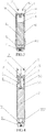
- a battery stick A for an oval-shaped electronic cigarette of the present invention can be connected with a vaporizer B of the electronic cigarette to constitute the electronic cigarette, and it serves to supply power for the vaporizer B of the electronic cigarette.
- the battery stick comprises a rod shaped housing 1 with oval-shaped cross section, a battery 2 accommodated in the housing 1, a control circuit board 3, and a power button 4, wherein the housing 1 has an open end and a closed end, such that the battery 2, the control circuit board 3 and the power button 4 can be loaded into the housing 1 via the open end of the housing 1, wherein a flat side wall of the housing 1 adjacent to the open end is provided with a first button hole 11 from which the power button 4 can protrude, an engagement portion 12 for fixed connection to the vaporizer B is arranged on an inner wall of the open end of housing 1.
- a mounting frame 5 is fitted inside the housing 1, wherein the mounting frame 5 comprises two sections, one of which is a circuit section 51 for fixedly mounting the control circuit board 3 and the other is a battery section 52 for fixedly mounting the battery 2.
- the circuit section 51 of the mounting frame 5 is arranged with a frame side plate 53 having the same curvature as the inner wall of the housing 1 at one side of the control circuit board 3. Since the frame side plate 53 has the same curvature as the inner wall of the housing 1, the mounting frame 5 can be fixedly arranged to abut against the inner wall of the housing 1 and prevented from loosing.
- a border of the mounting frame 5 proximal to the open end of the housing 1 is provided with two electrode mounting holes 60, and positive and negative electrodes 6 are disposed in the electrode mounting hole 60.
- the positive and negative electrodes 6 can be in contact with positive and negative electrodes (not shown in the drawings) of the vaporizer B, so as to allow the battery stick A to supply power for the vaporizer B.
- the mounting frame 5 comprises four rectangle borders, in which two long borders 54 are located at an outer wall of the battery section 52, have the same curvature as the inner wall of the housing 1 and abut tightly against the inner wall of the housing 1, and two short borders, including an outer border 551 and an inner border 552, are oval-shaped flat plates.
- a baffle plate 56 having a cut-out is arranged between the circuit section 51 and the battery section 52. The baffle plate 56 serves to retain the control circuit board 3 and fix the battery 2, and a wire connecting the battery with the circuit board can pass through the cut-out of the baffle plate 56.
- the control circuit board 3 can be configured to control the power supplied by means of the battery 2 of the battery stick and adjust the supply voltage and the supply current to facilitate stable operation.
- the control circuit board 3 is arranged with a press-type power switch 31.
- the power button 4 is arranged on the power switch 31 and is received in the first button hole 11. The user can press the power button 4 to perform an operation of the power switch 31.
- the circuit section 51 of the mounting frame 5 is arranged with a cover plate 8 having the same curvature as the inner wall of the housing 1 at another side of the control circuit board 3. Since the cover plate 8 has the same curvature as the inner wall of the housing 1, the cover plate 8 can abut tightly against the inner wall of the housing 1 and is prevented from loosing.
- the cover plate 8 is detachable, i.e., it is a type of removable cover plate.
- the cover plate 8 is provided with a second button hole 81 from which the power button 4 can protrude.
- a protruding ring 82 protruding upwards is arranged at a circumferential edge of the second button hole 81.
- the protruding ring 82 can be mounted in the first button hole 11, so as to fixedly mount the cover plate 8, and retain the power button 4 and prevent the power button 4 from loosing.
- the power button 4 is arranged on the power switch 31, and the cover plate 8 covers the control circuit board 3, with the power button 4 protruding from the second button hole 81.
- the power button 4 is arranged with a shoulder 41 at its bottom, and the shoulder 41 has an outer diameter greater than the diameter of the second button hole 81. Hence, the power button 4 can be retained inside the cover plate by the shoulder 41 and can be prevented from falling out from the second button hole 81.
- a wedge part 7 is arranged between the inner wall of the housing 1 and the frame side plate 53, and the wedge part 7 can be inserted via the open end of the housing 1.
- the wedge part 7 In the case that the wedge part 7 is inserted in place, it tightly presses the mounting frame 5 and the cover plate 8 against the inner wall of the housing 1, so as to secure the mounting frame 5 and the cover plate 8 and prevent the mounting frame 5 from loosing.
- An oval-shaped end panel 71 is arranged vertically at the wedge part 7, on the side proximal to the open end of the housing 1.
- the end panel 71 has a same cross section as the inner wall of the housing 1, such that the end panel 71 is retained by the inner wall of the housing 1 and its lateral movement is suppressed, and the mounting frame 5 is further secured.
- the end panel 71 is further provided with two electrode through holes 710, through which the positive and negative electrodes 6 can pass exactly.
- the wedge part 7 is inserted between the inner wall of the housing 1 and the frame side plate 53 in place, the end panel 71 abuts tightly against the outer border 551 of the mounting frame 5. Due to the wedge part 7, the present invention has simple assembly and reliable and firm connection.
- a snap fit structure 70 is provided between the frame side plate 53 and the wedge part 7, to enable a fixed connection there-between.
- the snap fit structure 70 may comprise a rectangle opening 701 provided on the frame side plate 53, a tongue 702 extending obliquely from the rectangle opening 701, and a snap-in hole 703 which is provided on the wedge part 7 and can be engaged with the tongue 702.
- the snap fit structure 70 may also be structures such as a structure of male snap and male snap, or a structure of male snap and snap-in hole.
- the engagement portion 12 may be a groove which is arranged on the inner wall of the housing 1 and can be connected with the outer wall of the connecting end of the vaporizer.
- the vaporizer B may be correspondingly arranged with a male snap which can be snap-fitted to the groove.
- a sliding groove 121 formed at an angle is further correspondingly arranged on the inner wall of the open end of housing 1 and is located outside the groove.
- the engagement portion 12 may also be a male snap, or other structure.
- the engagement portion 12 of the present invention has a simple and stable structure. It does not need metal screw joint structure which is usually required for the connection between the battery stick of conventional electronic cigarettes and the vaporizer and thus saves lots of metal materials.
- the closed end of the housing 1 is provided with an USB through hole 13 through which an USB charging connector (not shown in the drawings) can pass.
- the inner border 552 of the mounting frame 5 proximal to the closed end of the housing 1 is arranged with an interface circuit board 9.
- the interface circuit board 9 is arranged with an USB charging interface 91 to which the USB charging connector can be plugged.
- the USB charging interface 91 is a Micro-USB charging interface.
- the inner border 552 is arranged with a hook 553, and the interface circuit board 9 can be secured to the inner border 552 by the hook 553.
- the positive and negative electrodes 6 in the present invention may be elastic and stretchable electrodes.
- the positive and negative electrodes 6 which are elastic and stretchable can be in close contact with positive and negative electrodes (not shown in the drawings) of the vaporizer B so as to supply power.
- the battery 2, the circuit board 3, the power button 4, the positive and negative electrodes 6 and the cover plate 8 can be mounted on the mounting frame 5, and then the mounting frame 5 can be disposed in the housing 1. After that, the wedge part 7 can be inserted between the inner wall of the housing 1 and the mounting frame 5 to realize a fixed mounting. It realizes a simple and fast connection and greatly reduces labor costs during manufacturing.
Landscapes
- Chemical & Material Sciences (AREA)
- Chemical Kinetics & Catalysis (AREA)
- Electrochemistry (AREA)
- General Chemical & Material Sciences (AREA)
- Engineering & Computer Science (AREA)
- Microelectronics & Electronic Packaging (AREA)
- Manufacturing & Machinery (AREA)
- Power Engineering (AREA)
- Battery Mounting, Suspending (AREA)
Claims (10)
- Batteriestab (A) für die ovalförmige elektronische Zigarette, der mit einem Verdampfer (B) der elektronischen Zigarette verbunden werden kann, um die elektronische Zigarette zu bilden, und der dazu dient, Energie für den Verdampfer (B) der elektronischen Zigarette zu liefern, umfassend ein stabförmiges Gehäuse (1) mit einem ovalförmigen Querschnitt und eine Batterie (2), eine Steuerplatine (3) und eine An-Aus-Taste (4), die im Gehäuse (1) untergebracht sind, dadurch gekennzeichnet, dass das Gehäuse (1) ein offenes Ende und ein geschlossenes Ende aufweist, einen Eingriffsabschnitt (12) für eine feste Verbindung mit dem Verdampfer (B) an einer Innenwand des Gehäuses (1) in der Nähe des offenen Endes angeordnet ist, das Gehäuse (1) mit einem ersten Tastenloch (11) versehen ist, aus dem die An-Aus-Taste (4) vorstehen kann, und ein Montagerahmen (5) im Inneren des Gehäuses (1) angebracht ist, wobei der Montagerahmen (5) einen Schaltkreisabschnitt (51) zum Montieren der Steuerplatine (3) und einen Batterieabschnitt (52) zum Montieren der Batterie (2) umfasst, wobei der Schaltkreisabschnitt (51) des Montagerahmens (5) auf einer Seite der Steuerplatine (3) mit einer Rahmenseitenplatte (53) mit einer gleichen Krümmung wie die Innenwand des Gehäuses (1) angeordnet ist, ein äußerer Rand (551) des Montagerahmens (5) nahe dem offenen Ende des Gehäuses (1) mit positiven und negativen Elektroden (6) angeordnet ist; die Steuerplatine (3) mit einem Stromschalter vom Drucktyp (31) angeordnet ist, wobei die An-Aus-Taste (4) auf dem Stromschalter (31) angeordnet ist und im ersten Tastenloch (11) aufgenommen ist; ein Keilstück (7), das bemessen ist, über das offene Ende des Gehäuses (1) eingesetzt zu werden, zwischen der Innenwand des Gehäuses (1) und der Rahmenseitenplatte (53) angeordnet ist, um den Montagerahmen (5) zu sichern.
- Batteriestab (A) für die ovalförmige elektronische Zigarette nach Anspruch 1, dadurch gekennzeichnet, dass eine ovalförmige Endtafel (71) vertikal am Keilstück (7) auf der Seite nahe dem offenen Ende des Gehäuses (1) angeordnet ist, wobei die Endtafel (71) einen gleichen Querschnitt wie die Innenwand des Gehäuses (1) aufweist, die Endtafel (71) ferner mit zwei Elektrodendurchgangsbohrungen (710) versehen ist, durch die die positive und die negative Elektrode (6) treten können, und die Endtafel (71) eng an den äußeren Rand (551) des Montagerahmens (5) stößt.
- Batteriestab (A) für die ovalförmige elektronische Zigarette nach Anspruch 1, dadurch gekennzeichnet, dass eine Einschnappstruktur (70) zwischen der Rahmenseitenplatte (53) und dem Keilstück (7) vorgesehen ist, um eine feste Verbindung dazwischen zu ermöglichen.
- Batteriestab (A) für die ovalförmige elektronische Zigarette nach Anspruch 3, dadurch gekennzeichnet, dass die Einschnappstruktur (70) eine rechteckige Öffnung (701), die auf der Rahmenseitenplatte (53) vorgesehen ist, eine Zunge (702), die schräg von der rechteckigen Öffnung (701) verläuft, und ein Einschnapploch (703) umfasst, das auf dem Keilstück (7) vorgesehen ist und in das die Zunge (702) eingreifen kann.
- Batteriestab (A) für die ovalförmige elektronische Zigarette nach Anspruch 1, dadurch gekennzeichnet, dass der Montagerahmen (5) vier rechteckige Einfassungen (54; 551; 552) umfasst, in denen sich zwei lange Einfassungen (54) an einer Außenwand des Batterieabschnitts (52) befinden und mit einer Krümmung gebildet sind, sodass die zwei langen Einfassungen (54) eng an die Innenwand des Gehäuses (1) stoßen können, und zwei kurze Einfassungen (551; 552), einschließlich einer äußeren Einfassung (551) und einer inneren Einfassung (552), ovalförmige flache Platten (551; 552) sind, die an zwei inneren Enden des Gehäuses (1) angeordnet sind, und eine Leitplatte (56) mit einem Ausschnitt zwischen dem Schaltkreisabschnitt (51) und dem Batterieabschnitt (52) angeordnet ist.
- Batteriestab (A) für die ovalförmige elektronische Zigarette nach Anspruch 5, dadurch gekennzeichnet, dass zwei Seiten der Steuerplatine (3) an den langen Einfassungen (54) des Schaltkreisabschnitts (51) des Montagerahmens (5) gehalten und montiert sind und die anderen zwei Seiten der Steuerplatine (3) zwischen die Leitplatte (56) und die äußere Einfassung (551) gesteckt und montiert sind.
- Batteriestab (A) für die ovalförmige elektronische Zigarette nach Anspruch 1, dadurch gekennzeichnet, dass der Schaltkreisabschnitt (51) des Montagerahmens (5) auf einer anderen Seite der Steuerplatine (3) mit einer abnehmbaren Deckplatte (8) mit der gleichen Krümmung wie die Innenwand des Gehäuses (1) angeordnet ist, wobei die Deckplatte (8) mit einem zweiten Tastenloch (81) versehen ist, aus dem die An-Aus-Taste (4) vorstehen kann, wobei ein vorstehender Ring (82), der nach oben vorsteht, an einer Umfangskante des zweiten Tastenlochs (81) angeordnet ist und der vorstehende Ring (82) im ersten Tastenloch (11) montiert ist, wobei die An-Aus-Taste (4) an ihrem Boden mit einer Schulter (41) versehen ist, um zu verhindern, dass die An-Aus-Taste (4) aus dem zweiten Tastenloch (81) fällt.
- Batteriestab (A) für die ovalförmige elektronische Zigarette nach Anspruch 1, dadurch gekennzeichnet, dass der Eingriffsabschnitt (12) einen Steckschnapper oder eine Nut zum Verbinden mit einer Außenwand eines Verbindungsendes des Verdampfers (B) umfasst und der Steckschnapper oder die Nut auf der Innenwand des Gehäuses (1) angeordnet ist.
- Batteriestab (A) für die ovalförmige elektronische Zigarette nach Anspruch 1, dadurch gekennzeichnet, dass das geschlossene Ende des Gehäuses (1) mit einer USB-Durchgangsbohrung (13) versehen ist, durch die ein USB-Ladeverbinder treten kann, die innere Einfassung (552) des Montagerahmens (5) nahe dem geschlossenen Ende des Gehäuses (1) mit einer Schnittstellenplatine (9) versehen ist und die Schnittstellenplatine (9) mit einer USB-Ladeschnittstelle (91) versehen ist, in die der USB-Ladeverbindung gesteckt werden kann.
- Batteriestab (A) für die ovalförmige elektronische Zigarette nach Anspruch 1, dadurch gekennzeichnet, dass die positive und die negative Elektrode (6) elastische und dehnbare Elektroden (6) sind.
Priority Applications (1)
| Application Number | Priority Date | Filing Date | Title |
|---|---|---|---|
| PL17860918T PL3518311T3 (pl) | 2016-10-14 | 2017-09-08 | Eliptyczny wkład baterii do elektronicznego papierosa |
Applications Claiming Priority (2)
| Application Number | Priority Date | Filing Date | Title |
|---|---|---|---|
| CN201610900334.3A CN106343611B (zh) | 2016-10-14 | 2016-10-14 | 椭圆形电子烟的电池杆 |
| PCT/CN2017/101103 WO2018068602A1 (zh) | 2016-10-14 | 2017-09-08 | 椭圆形电子烟的电池杆 |
Publications (3)
| Publication Number | Publication Date |
|---|---|
| EP3518311A1 EP3518311A1 (de) | 2019-07-31 |
| EP3518311A4 EP3518311A4 (de) | 2019-11-06 |
| EP3518311B1 true EP3518311B1 (de) | 2020-10-07 |
Family
ID=57865763
Family Applications (1)
| Application Number | Title | Priority Date | Filing Date |
|---|---|---|---|
| EP17860918.6A Not-in-force EP3518311B1 (de) | 2016-10-14 | 2017-09-08 | Elliptischer batteriestab für elektronische zigarette |
Country Status (9)
| Country | Link |
|---|---|
| US (1) | US11129412B2 (de) |
| EP (1) | EP3518311B1 (de) |
| CN (1) | CN106343611B (de) |
| DK (1) | DK3518311T3 (de) |
| ES (1) | ES2836141T3 (de) |
| HU (1) | HUE052992T2 (de) |
| PL (1) | PL3518311T3 (de) |
| PT (1) | PT3518311T (de) |
| WO (1) | WO2018068602A1 (de) |
Families Citing this family (33)
| Publication number | Priority date | Publication date | Assignee | Title |
|---|---|---|---|---|
| CN106343611B (zh) * | 2016-10-14 | 2019-08-27 | 惠州市新泓威科技有限公司 | 椭圆形电子烟的电池杆 |
| CN108201179B (zh) * | 2018-04-02 | 2024-06-28 | 上海新型烟草制品研究院有限公司 | 用于气雾产生装置的电池组件及气雾产生装置 |
| CN110639103B (zh) * | 2018-06-27 | 2023-04-07 | 尤尔实验室有限公司 | 蒸发器装置 |
| US10888125B2 (en) | 2018-06-27 | 2021-01-12 | Juul Labs, Inc. | Vaporizer device with subassemblies |
| JP6582362B1 (ja) * | 2018-10-26 | 2019-10-02 | 日本たばこ産業株式会社 | 非燃焼式吸引器の電源ユニット及び非燃焼式吸引器 |
| CN111096486A (zh) * | 2018-10-26 | 2020-05-05 | 日本烟草产业株式会社 | 非燃烧式抽吸器的电源单元、主体单元及非燃烧式抽吸器 |
| CN111096487A (zh) * | 2018-10-26 | 2020-05-05 | 日本烟草产业株式会社 | 非燃烧式抽吸器的电源单元、主体单元及非燃烧式抽吸器 |
| CN111358058A (zh) * | 2018-12-26 | 2020-07-03 | 常州市派腾电子技术服务有限公司 | 电池壳及电子烟、装配方法 |
| CN111434257A (zh) * | 2018-12-26 | 2020-07-21 | 常州市派腾电子技术服务有限公司 | 电源装置及电子烟、装配方法 |
| JP6647435B1 (ja) | 2019-01-17 | 2020-02-14 | 日本たばこ産業株式会社 | エアロゾル吸引器用の電源ユニット |
| CN111466619A (zh) * | 2019-01-23 | 2020-07-31 | 湖南中烟工业有限责任公司 | 低温烟具 |
| GB201902220D0 (en) * | 2019-02-18 | 2019-04-03 | Nicoventures Trading Ltd | Aerosol provision systems |
| TW202037291A (zh) * | 2019-03-11 | 2020-10-16 | 英商尼可創業貿易有限公司 | 氣溶膠供給裝置 |
| EP3937686B1 (de) | 2019-03-11 | 2024-12-18 | Nicoventures Trading Limited | Aerosol erzeugende vorrichtung |
| USD930237S1 (en) * | 2019-04-14 | 2021-09-07 | 14Th Round Inc. | Mouthpiece |
| USD930896S1 (en) * | 2019-04-14 | 2021-09-14 | 14Th Round Inc. | Vaporization device |
| JP2022120203A (ja) * | 2019-04-19 | 2022-08-18 | 株式会社村田製作所 | 電池パック、非燃焼式吸引器、電子機器及び電動工具 |
| CN210169056U (zh) * | 2019-05-08 | 2020-03-24 | 深圳麦克韦尔科技有限公司 | 电子雾化装置及其雾化器和吸嘴单元 |
| CN110226779A (zh) * | 2019-06-27 | 2019-09-13 | 深圳雾芯科技有限公司 | 电子雾化器及电子雾化器装置 |
| CN110403254A (zh) * | 2019-08-26 | 2019-11-05 | 惠州市新泓威科技有限公司 | 电子烟的电池杆 |
| WO2021042288A1 (zh) * | 2019-09-04 | 2021-03-11 | 深圳市大疆创新科技有限公司 | 安装组件、壳体组件、电池及用电设备 |
| USD930234S1 (en) * | 2019-09-24 | 2021-09-07 | Shenzhen Smoore Technology Limited | Electronic atomizing device |
| CN110754691A (zh) * | 2019-11-04 | 2020-02-07 | 深圳雾芯科技有限公司 | 一种用于电子烟之固定构件及电子烟组件之固定方法 |
| EP4195386A4 (de) * | 2020-08-07 | 2024-12-18 | Eagle Industry Co., Ltd. | Elektronische vorrichtung |
| CN112490572B (zh) * | 2020-11-18 | 2025-11-18 | 深圳麦克韦尔科技有限公司 | 电子雾化装置及其供电组件和支架 |
| CN113142660A (zh) * | 2020-12-25 | 2021-07-23 | 深圳市斯科尔科技有限公司 | 供电装置及电子烟 |
| CN117098943A (zh) | 2021-03-29 | 2023-11-21 | 伊格尔工业股份有限公司 | 阀 |
| KR102579821B1 (ko) * | 2021-06-23 | 2023-09-15 | 주식회사 케이티앤지 | 에어로졸 생성 장치 |
| CN114094272B (zh) * | 2021-12-17 | 2024-08-27 | 珠海格力电器股份有限公司 | 一种电池仓和电器设备 |
| WO2023195770A1 (en) * | 2022-04-06 | 2023-10-12 | Kt&G Corporation | Aerosol generating device |
| CA215310S (en) * | 2022-04-30 | 2023-06-22 | Huizhou Babo Tech Co Ltd | Electronic cigarette |
| JP1739664S (ja) * | 2022-07-13 | 2023-03-22 | 電子タバコ | |
| CN116344903B (zh) * | 2023-04-04 | 2025-10-03 | 惠州市纬世新能源有限公司 | 一种用于加热不燃烧烟具的电池 |
Family Cites Families (16)
| Publication number | Priority date | Publication date | Assignee | Title |
|---|---|---|---|---|
| CN201468001U (zh) * | 2009-06-05 | 2010-05-19 | 谢舜尧 | 一种电子烟 |
| US20140041655A1 (en) * | 2012-08-11 | 2014-02-13 | Grenco Science, Inc | Portable Vaporizer |
| KR200466757Y1 (ko) * | 2012-11-01 | 2013-05-06 | (주)잔티아시아 | 다기능 제어수단을 갖는 스마트 전자담배 |
| CN203633501U (zh) * | 2013-07-15 | 2014-06-11 | 刘秋明 | 电子烟 |
| CN203353689U (zh) * | 2013-07-24 | 2013-12-25 | 刘秋明 | 电子烟 |
| CN203555163U (zh) * | 2013-08-12 | 2014-04-23 | 深圳市合元科技有限公司 | 电子烟用电池组件及电子烟 |
| CN103682203B (zh) * | 2013-11-29 | 2016-03-02 | 深圳市合元科技有限公司 | 电子烟用电池组件及其组装方法 |
| CN203762298U (zh) * | 2014-01-21 | 2014-08-13 | 深圳市合元科技有限公司 | 电子烟用供电装置及电子烟 |
| CN203873003U (zh) * | 2014-04-16 | 2014-10-15 | 林光榕 | 电子烟 |
| CN105024412B (zh) * | 2014-04-18 | 2018-03-06 | 深圳哈卡香料科技有限公司 | 具有开关显示功能的电源组件及电子烟 |
| CN203883521U (zh) * | 2014-05-15 | 2014-10-15 | 林光榕 | 电子烟磁吸式充电装置 |
| CN204045662U (zh) * | 2014-06-06 | 2014-12-24 | 黄金珍 | 一种电子烟电池 |
| CN203952447U (zh) * | 2014-06-25 | 2014-11-26 | 林光榕 | 电子烟 |
| CN104799434B (zh) * | 2015-03-30 | 2017-06-23 | 刘团芳 | 一种香烟烘烤器 |
| CN206165814U (zh) | 2016-10-14 | 2017-05-17 | 林光榕 | 椭圆形电子烟的电池杆 |
| CN106343611B (zh) * | 2016-10-14 | 2019-08-27 | 惠州市新泓威科技有限公司 | 椭圆形电子烟的电池杆 |
-
2016
- 2016-10-14 CN CN201610900334.3A patent/CN106343611B/zh active Active
-
2017
- 2017-09-08 WO PCT/CN2017/101103 patent/WO2018068602A1/zh not_active Ceased
- 2017-09-08 ES ES17860918T patent/ES2836141T3/es active Active
- 2017-09-08 HU HUE17860918A patent/HUE052992T2/hu unknown
- 2017-09-08 PT PT178609186T patent/PT3518311T/pt unknown
- 2017-09-08 EP EP17860918.6A patent/EP3518311B1/de not_active Not-in-force
- 2017-09-08 US US16/341,456 patent/US11129412B2/en active Active
- 2017-09-08 DK DK17860918.6T patent/DK3518311T3/da active
- 2017-09-08 PL PL17860918T patent/PL3518311T3/pl unknown
Non-Patent Citations (1)
| Title |
|---|
| None * |
Also Published As
| Publication number | Publication date |
|---|---|
| US11129412B2 (en) | 2021-09-28 |
| EP3518311A4 (de) | 2019-11-06 |
| EP3518311A1 (de) | 2019-07-31 |
| DK3518311T3 (da) | 2020-10-26 |
| US20190261690A1 (en) | 2019-08-29 |
| CN106343611B (zh) | 2019-08-27 |
| ES2836141T3 (es) | 2021-06-24 |
| CN106343611A (zh) | 2017-01-25 |
| HUE052992T2 (hu) | 2021-06-28 |
| PL3518311T3 (pl) | 2021-01-25 |
| WO2018068602A1 (zh) | 2018-04-19 |
| PT3518311T (pt) | 2020-11-30 |
Similar Documents
| Publication | Publication Date | Title |
|---|---|---|
| EP3518311B1 (de) | Elliptischer batteriestab für elektronische zigarette | |
| US11723404B2 (en) | Electronic cigarette vaporizer avoiding liquid leakage during using | |
| US9526273B2 (en) | Electronic cigarette | |
| EP3590365A1 (de) | Heizvorrichtung und elektronische zigarette damit | |
| JP3164408U (ja) | 電子タバコ用の充電器 | |
| US20160270445A1 (en) | Electronic cigarette | |
| US20150351455A1 (en) | Electronic cigarette and electronic cigarette device thereof | |
| US10165800B2 (en) | Battery device and electronic cigarette having the same | |
| HK1258059A1 (zh) | 电源组件、非燃烧型香味吸取器以及非燃烧型香味吸取系统 | |
| US11013272B2 (en) | Electronic cigarette | |
| KR101329162B1 (ko) | 전자담배 | |
| CN209314965U (zh) | 一种电池可更换的电子烟 | |
| CN203555163U (zh) | 电子烟用电池组件及电子烟 | |
| EP3881691B1 (de) | Zerstäubungsanordnung und elektronische zigarette damit | |
| CN212163635U (zh) | 耳机组件 | |
| JP3217944U (ja) | 電子タバコ用吸引補助装置 | |
| CN204407377U (zh) | 一种具有磁吸式后盖的电子烟电池 | |
| CN206165814U (zh) | 椭圆形电子烟的电池杆 | |
| CN209825208U (zh) | 加热非燃烧型烟弹及电子烟 | |
| CN215583169U (zh) | 一种内托支架及气溶胶发生装置 | |
| CN113811208A (zh) | 电连接器、供电电源、雾化器及电子烟 | |
| CN210642464U (zh) | 一种电子烟雾化器 | |
| CN210203315U (zh) | 电子烟 | |
| CN210538924U (zh) | 烟油雾化器、电子烟和电子烟组件 | |
| KR101550332B1 (ko) | 아날로그 작동식 전자담배 |
Legal Events
| Date | Code | Title | Description |
|---|---|---|---|
| STAA | Information on the status of an ep patent application or granted ep patent |
Free format text: STATUS: THE INTERNATIONAL PUBLICATION HAS BEEN MADE |
|
| PUAI | Public reference made under article 153(3) epc to a published international application that has entered the european phase |
Free format text: ORIGINAL CODE: 0009012 |
|
| STAA | Information on the status of an ep patent application or granted ep patent |
Free format text: STATUS: REQUEST FOR EXAMINATION WAS MADE |
|
| 17P | Request for examination filed |
Effective date: 20190423 |
|
| AK | Designated contracting states |
Kind code of ref document: A1 Designated state(s): AL AT BE BG CH CY CZ DE DK EE ES FI FR GB GR HR HU IE IS IT LI LT LU LV MC MK MT NL NO PL PT RO RS SE SI SK SM TR |
|
| AX | Request for extension of the european patent |
Extension state: BA ME |
|
| REG | Reference to a national code |
Ref country code: DE Ref legal event code: R079 Ref document number: 602017025226 Country of ref document: DE Free format text: PREVIOUS MAIN CLASS: H01M0002100000 Ipc: A24F0047000000 |
|
| A4 | Supplementary search report drawn up and despatched |
Effective date: 20191008 |
|
| RIC1 | Information provided on ipc code assigned before grant |
Ipc: A24F 47/00 20060101AFI20191001BHEP Ipc: H01M 2/10 20060101ALI20191001BHEP |
|
| DAV | Request for validation of the european patent (deleted) | ||
| DAX | Request for extension of the european patent (deleted) | ||
| GRAP | Despatch of communication of intention to grant a patent |
Free format text: ORIGINAL CODE: EPIDOSNIGR1 |
|
| STAA | Information on the status of an ep patent application or granted ep patent |
Free format text: STATUS: GRANT OF PATENT IS INTENDED |
|
| INTG | Intention to grant announced |
Effective date: 20200407 |
|
| GRAS | Grant fee paid |
Free format text: ORIGINAL CODE: EPIDOSNIGR3 |
|
| GRAA | (expected) grant |
Free format text: ORIGINAL CODE: 0009210 |
|
| STAA | Information on the status of an ep patent application or granted ep patent |
Free format text: STATUS: THE PATENT HAS BEEN GRANTED |
|
| AK | Designated contracting states |
Kind code of ref document: B1 Designated state(s): AL AT BE BG CH CY CZ DE DK EE ES FI FR GB GR HR HU IE IS IT LI LT LU LV MC MK MT NL NO PL PT RO RS SE SI SK SM TR |
|
| REG | Reference to a national code |
Ref country code: GB Ref legal event code: FG4D |
|
| REG | Reference to a national code |
Ref country code: CH Ref legal event code: EP Ref country code: AT Ref legal event code: REF Ref document number: 1320222 Country of ref document: AT Kind code of ref document: T Effective date: 20201015 |
|
| REG | Reference to a national code |
Ref country code: DK Ref legal event code: T3 Effective date: 20201021 |
|
| REG | Reference to a national code |
Ref country code: IE Ref legal event code: FG4D |
|
| REG | Reference to a national code |
Ref country code: DE Ref legal event code: R096 Ref document number: 602017025226 Country of ref document: DE |
|
| REG | Reference to a national code |
Ref country code: CH Ref legal event code: NV Representative=s name: MEYER AND KOLLEGEN, CH |
|
| REG | Reference to a national code |
Ref country code: PT Ref legal event code: SC4A Ref document number: 3518311 Country of ref document: PT Date of ref document: 20201130 Kind code of ref document: T Free format text: AVAILABILITY OF NATIONAL TRANSLATION Effective date: 20201124 |
|
| REG | Reference to a national code |
Ref country code: NL Ref legal event code: FP |
|
| REG | Reference to a national code |
Ref country code: GR Ref legal event code: EP Ref document number: 20210400011 Country of ref document: GR Effective date: 20210215 |
|
| PG25 | Lapsed in a contracting state [announced via postgrant information from national office to epo] |
Ref country code: NO Free format text: LAPSE BECAUSE OF FAILURE TO SUBMIT A TRANSLATION OF THE DESCRIPTION OR TO PAY THE FEE WITHIN THE PRESCRIBED TIME-LIMIT Effective date: 20210107 Ref country code: RS Free format text: LAPSE BECAUSE OF FAILURE TO SUBMIT A TRANSLATION OF THE DESCRIPTION OR TO PAY THE FEE WITHIN THE PRESCRIBED TIME-LIMIT Effective date: 20201007 Ref country code: FI Free format text: LAPSE BECAUSE OF FAILURE TO SUBMIT A TRANSLATION OF THE DESCRIPTION OR TO PAY THE FEE WITHIN THE PRESCRIBED TIME-LIMIT Effective date: 20201007 |
|
| REG | Reference to a national code |
Ref country code: LT Ref legal event code: MG4D |
|
| PG25 | Lapsed in a contracting state [announced via postgrant information from national office to epo] |
Ref country code: BG Free format text: LAPSE BECAUSE OF FAILURE TO SUBMIT A TRANSLATION OF THE DESCRIPTION OR TO PAY THE FEE WITHIN THE PRESCRIBED TIME-LIMIT Effective date: 20210107 Ref country code: LV Free format text: LAPSE BECAUSE OF FAILURE TO SUBMIT A TRANSLATION OF THE DESCRIPTION OR TO PAY THE FEE WITHIN THE PRESCRIBED TIME-LIMIT Effective date: 20201007 Ref country code: IS Free format text: LAPSE BECAUSE OF FAILURE TO SUBMIT A TRANSLATION OF THE DESCRIPTION OR TO PAY THE FEE WITHIN THE PRESCRIBED TIME-LIMIT Effective date: 20210207 Ref country code: SE Free format text: LAPSE BECAUSE OF FAILURE TO SUBMIT A TRANSLATION OF THE DESCRIPTION OR TO PAY THE FEE WITHIN THE PRESCRIBED TIME-LIMIT Effective date: 20201007 |
|
| REG | Reference to a national code |
Ref country code: ES Ref legal event code: FG2A Ref document number: 2836141 Country of ref document: ES Kind code of ref document: T3 Effective date: 20210624 |
|
| REG | Reference to a national code |
Ref country code: HU Ref legal event code: AG4A Ref document number: E052992 Country of ref document: HU |
|
| PG25 | Lapsed in a contracting state [announced via postgrant information from national office to epo] |
Ref country code: HR Free format text: LAPSE BECAUSE OF FAILURE TO SUBMIT A TRANSLATION OF THE DESCRIPTION OR TO PAY THE FEE WITHIN THE PRESCRIBED TIME-LIMIT Effective date: 20201007 |
|
| REG | Reference to a national code |
Ref country code: DE Ref legal event code: R097 Ref document number: 602017025226 Country of ref document: DE |
|
| PG25 | Lapsed in a contracting state [announced via postgrant information from national office to epo] |
Ref country code: LT Free format text: LAPSE BECAUSE OF FAILURE TO SUBMIT A TRANSLATION OF THE DESCRIPTION OR TO PAY THE FEE WITHIN THE PRESCRIBED TIME-LIMIT Effective date: 20201007 Ref country code: EE Free format text: LAPSE BECAUSE OF FAILURE TO SUBMIT A TRANSLATION OF THE DESCRIPTION OR TO PAY THE FEE WITHIN THE PRESCRIBED TIME-LIMIT Effective date: 20201007 Ref country code: SM Free format text: LAPSE BECAUSE OF FAILURE TO SUBMIT A TRANSLATION OF THE DESCRIPTION OR TO PAY THE FEE WITHIN THE PRESCRIBED TIME-LIMIT Effective date: 20201007 Ref country code: RO Free format text: LAPSE BECAUSE OF FAILURE TO SUBMIT A TRANSLATION OF THE DESCRIPTION OR TO PAY THE FEE WITHIN THE PRESCRIBED TIME-LIMIT Effective date: 20201007 Ref country code: SK Free format text: LAPSE BECAUSE OF FAILURE TO SUBMIT A TRANSLATION OF THE DESCRIPTION OR TO PAY THE FEE WITHIN THE PRESCRIBED TIME-LIMIT Effective date: 20201007 |
|
| PLBE | No opposition filed within time limit |
Free format text: ORIGINAL CODE: 0009261 |
|
| STAA | Information on the status of an ep patent application or granted ep patent |
Free format text: STATUS: NO OPPOSITION FILED WITHIN TIME LIMIT |
|
| 26N | No opposition filed |
Effective date: 20210708 |
|
| PG25 | Lapsed in a contracting state [announced via postgrant information from national office to epo] |
Ref country code: AL Free format text: LAPSE BECAUSE OF FAILURE TO SUBMIT A TRANSLATION OF THE DESCRIPTION OR TO PAY THE FEE WITHIN THE PRESCRIBED TIME-LIMIT Effective date: 20201007 |
|
| PGFP | Annual fee paid to national office [announced via postgrant information from national office to epo] |
Ref country code: IE Payment date: 20210927 Year of fee payment: 5 Ref country code: CH Payment date: 20210920 Year of fee payment: 5 Ref country code: CZ Payment date: 20210902 Year of fee payment: 5 Ref country code: NL Payment date: 20210916 Year of fee payment: 5 |
|
| PG25 | Lapsed in a contracting state [announced via postgrant information from national office to epo] |
Ref country code: SI Free format text: LAPSE BECAUSE OF FAILURE TO SUBMIT A TRANSLATION OF THE DESCRIPTION OR TO PAY THE FEE WITHIN THE PRESCRIBED TIME-LIMIT Effective date: 20201007 |
|
| PGFP | Annual fee paid to national office [announced via postgrant information from national office to epo] |
Ref country code: TR Payment date: 20210901 Year of fee payment: 5 Ref country code: DK Payment date: 20210927 Year of fee payment: 5 Ref country code: GR Payment date: 20210920 Year of fee payment: 5 Ref country code: PL Payment date: 20210902 Year of fee payment: 5 Ref country code: HU Payment date: 20210920 Year of fee payment: 5 Ref country code: BE Payment date: 20210927 Year of fee payment: 5 |
|
| PGFP | Annual fee paid to national office [announced via postgrant information from national office to epo] |
Ref country code: PT Payment date: 20210831 Year of fee payment: 5 |
|
| PGFP | Annual fee paid to national office [announced via postgrant information from national office to epo] |
Ref country code: ES Payment date: 20211005 Year of fee payment: 5 |
|
| REG | Reference to a national code |
Ref country code: AT Ref legal event code: UEP Ref document number: 1320222 Country of ref document: AT Kind code of ref document: T Effective date: 20201007 |
|
| PG25 | Lapsed in a contracting state [announced via postgrant information from national office to epo] |
Ref country code: IS Free format text: LAPSE BECAUSE OF FAILURE TO SUBMIT A TRANSLATION OF THE DESCRIPTION OR TO PAY THE FEE WITHIN THE PRESCRIBED TIME-LIMIT Effective date: 20210207 Ref country code: MC Free format text: LAPSE BECAUSE OF FAILURE TO SUBMIT A TRANSLATION OF THE DESCRIPTION OR TO PAY THE FEE WITHIN THE PRESCRIBED TIME-LIMIT Effective date: 20201007 |
|
| PG25 | Lapsed in a contracting state [announced via postgrant information from national office to epo] |
Ref country code: LU Free format text: LAPSE BECAUSE OF NON-PAYMENT OF DUE FEES Effective date: 20210908 |
|
| PGFP | Annual fee paid to national office [announced via postgrant information from national office to epo] |
Ref country code: FR Payment date: 20220930 Year of fee payment: 6 |
|
| PGFP | Annual fee paid to national office [announced via postgrant information from national office to epo] |
Ref country code: IT Payment date: 20220915 Year of fee payment: 6 Ref country code: GB Payment date: 20221027 Year of fee payment: 6 Ref country code: DE Payment date: 20221012 Year of fee payment: 6 |
|
| PG25 | Lapsed in a contracting state [announced via postgrant information from national office to epo] |
Ref country code: PT Free format text: LAPSE BECAUSE OF NON-PAYMENT OF DUE FEES Effective date: 20230308 Ref country code: CZ Free format text: LAPSE BECAUSE OF NON-PAYMENT OF DUE FEES Effective date: 20220908 |
|
| REG | Reference to a national code |
Ref country code: CH Ref legal event code: PL |
|
| REG | Reference to a national code |
Ref country code: DK Ref legal event code: EBP Effective date: 20220930 |
|
| REG | Reference to a national code |
Ref country code: NL Ref legal event code: MM Effective date: 20221001 |
|
| REG | Reference to a national code |
Ref country code: BE Ref legal event code: MM Effective date: 20220930 |
|
| PG25 | Lapsed in a contracting state [announced via postgrant information from national office to epo] |
Ref country code: CY Free format text: LAPSE BECAUSE OF FAILURE TO SUBMIT A TRANSLATION OF THE DESCRIPTION OR TO PAY THE FEE WITHIN THE PRESCRIBED TIME-LIMIT Effective date: 20201007 Ref country code: NL Free format text: LAPSE BECAUSE OF NON-PAYMENT OF DUE FEES Effective date: 20221001 |
|
| P01 | Opt-out of the competence of the unified patent court (upc) registered |
Effective date: 20230601 |
|
| PG25 | Lapsed in a contracting state [announced via postgrant information from national office to epo] |
Ref country code: LI Free format text: LAPSE BECAUSE OF NON-PAYMENT OF DUE FEES Effective date: 20220930 Ref country code: IE Free format text: LAPSE BECAUSE OF NON-PAYMENT OF DUE FEES Effective date: 20220908 Ref country code: HU Free format text: LAPSE BECAUSE OF NON-PAYMENT OF DUE FEES Effective date: 20220909 Ref country code: CH Free format text: LAPSE BECAUSE OF NON-PAYMENT OF DUE FEES Effective date: 20220930 |
|
| PG25 | Lapsed in a contracting state [announced via postgrant information from national office to epo] |
Ref country code: GR Free format text: LAPSE BECAUSE OF NON-PAYMENT OF DUE FEES Effective date: 20230406 |
|
| PG25 | Lapsed in a contracting state [announced via postgrant information from national office to epo] |
Ref country code: BE Free format text: LAPSE BECAUSE OF NON-PAYMENT OF DUE FEES Effective date: 20220930 |
|
| REG | Reference to a national code |
Ref country code: ES Ref legal event code: FD2A Effective date: 20231027 |
|
| PG25 | Lapsed in a contracting state [announced via postgrant information from national office to epo] |
Ref country code: DK Free format text: LAPSE BECAUSE OF NON-PAYMENT OF DUE FEES Effective date: 20220930 |
|
| REG | Reference to a national code |
Ref country code: AT Ref legal event code: MM01 Ref document number: 1320222 Country of ref document: AT Kind code of ref document: T Effective date: 20220908 |
|
| PG25 | Lapsed in a contracting state [announced via postgrant information from national office to epo] |
Ref country code: ES Free format text: LAPSE BECAUSE OF NON-PAYMENT OF DUE FEES Effective date: 20220909 |
|
| PG25 | Lapsed in a contracting state [announced via postgrant information from national office to epo] |
Ref country code: ES Free format text: LAPSE BECAUSE OF NON-PAYMENT OF DUE FEES Effective date: 20220909 Ref country code: AT Free format text: LAPSE BECAUSE OF NON-PAYMENT OF DUE FEES Effective date: 20220908 |
|
| REG | Reference to a national code |
Ref country code: DE Ref legal event code: R119 Ref document number: 602017025226 Country of ref document: DE |
|
| PG25 | Lapsed in a contracting state [announced via postgrant information from national office to epo] |
Ref country code: MK Free format text: LAPSE BECAUSE OF FAILURE TO SUBMIT A TRANSLATION OF THE DESCRIPTION OR TO PAY THE FEE WITHIN THE PRESCRIBED TIME-LIMIT Effective date: 20201007 |
|
| GBPC | Gb: european patent ceased through non-payment of renewal fee |
Effective date: 20230908 |
|
| PG25 | Lapsed in a contracting state [announced via postgrant information from national office to epo] |
Ref country code: PL Free format text: LAPSE BECAUSE OF NON-PAYMENT OF DUE FEES Effective date: 20220908 |
|
| PG25 | Lapsed in a contracting state [announced via postgrant information from national office to epo] |
Ref country code: GB Free format text: LAPSE BECAUSE OF NON-PAYMENT OF DUE FEES Effective date: 20230908 |
|
| PG25 | Lapsed in a contracting state [announced via postgrant information from national office to epo] |
Ref country code: GB Free format text: LAPSE BECAUSE OF NON-PAYMENT OF DUE FEES Effective date: 20230908 Ref country code: FR Free format text: LAPSE BECAUSE OF NON-PAYMENT OF DUE FEES Effective date: 20230930 Ref country code: DE Free format text: LAPSE BECAUSE OF NON-PAYMENT OF DUE FEES Effective date: 20240403 |
|
| PG25 | Lapsed in a contracting state [announced via postgrant information from national office to epo] |
Ref country code: TR Free format text: LAPSE BECAUSE OF NON-PAYMENT OF DUE FEES Effective date: 20220908 Ref country code: MT Free format text: LAPSE BECAUSE OF FAILURE TO SUBMIT A TRANSLATION OF THE DESCRIPTION OR TO PAY THE FEE WITHIN THE PRESCRIBED TIME-LIMIT Effective date: 20201007 |
|
| PG25 | Lapsed in a contracting state [announced via postgrant information from national office to epo] |
Ref country code: IT Free format text: LAPSE BECAUSE OF NON-PAYMENT OF DUE FEES Effective date: 20230908 |
|
| PG25 | Lapsed in a contracting state [announced via postgrant information from national office to epo] |
Ref country code: IT Free format text: LAPSE BECAUSE OF NON-PAYMENT OF DUE FEES Effective date: 20230908 |