EP3518021A1 - Translucent cover member for head-up display device and head-up display device - Google Patents
Translucent cover member for head-up display device and head-up display device Download PDFInfo
- Publication number
- EP3518021A1 EP3518021A1 EP17852888.1A EP17852888A EP3518021A1 EP 3518021 A1 EP3518021 A1 EP 3518021A1 EP 17852888 A EP17852888 A EP 17852888A EP 3518021 A1 EP3518021 A1 EP 3518021A1
- Authority
- EP
- European Patent Office
- Prior art keywords
- head
- display
- display device
- cover member
- translucent cover
- Prior art date
- Legal status (The legal status is an assumption and is not a legal conclusion. Google has not performed a legal analysis and makes no representation as to the accuracy of the status listed.)
- Granted
Links
Images

Classifications
-
- B—PERFORMING OPERATIONS; TRANSPORTING
- B32—LAYERED PRODUCTS
- B32B—LAYERED PRODUCTS, i.e. PRODUCTS BUILT-UP OF STRATA OF FLAT OR NON-FLAT, e.g. CELLULAR OR HONEYCOMB, FORM
- B32B17/00—Layered products essentially comprising sheet glass, or glass, slag, or like fibres
- B32B17/06—Layered products essentially comprising sheet glass, or glass, slag, or like fibres comprising glass as the main or only constituent of a layer, next to another layer of a specific material
- B32B17/10—Layered products essentially comprising sheet glass, or glass, slag, or like fibres comprising glass as the main or only constituent of a layer, next to another layer of a specific material of synthetic resin
- B32B17/10005—Layered products essentially comprising sheet glass, or glass, slag, or like fibres comprising glass as the main or only constituent of a layer, next to another layer of a specific material of synthetic resin laminated safety glass or glazing
- B32B17/10009—Layered products essentially comprising sheet glass, or glass, slag, or like fibres comprising glass as the main or only constituent of a layer, next to another layer of a specific material of synthetic resin laminated safety glass or glazing characterized by the number, the constitution or treatment of glass sheets
- B32B17/10036—Layered products essentially comprising sheet glass, or glass, slag, or like fibres comprising glass as the main or only constituent of a layer, next to another layer of a specific material of synthetic resin laminated safety glass or glazing characterized by the number, the constitution or treatment of glass sheets comprising two outer glass sheets
-
- B—PERFORMING OPERATIONS; TRANSPORTING
- B60—VEHICLES IN GENERAL
- B60K—ARRANGEMENT OR MOUNTING OF PROPULSION UNITS OR OF TRANSMISSIONS IN VEHICLES; ARRANGEMENT OR MOUNTING OF PLURAL DIVERSE PRIME-MOVERS IN VEHICLES; AUXILIARY DRIVES FOR VEHICLES; INSTRUMENTATION OR DASHBOARDS FOR VEHICLES; ARRANGEMENTS IN CONNECTION WITH COOLING, AIR INTAKE, GAS EXHAUST OR FUEL SUPPLY OF PROPULSION UNITS IN VEHICLES
- B60K35/00—Instruments specially adapted for vehicles; Arrangement of instruments in or on vehicles
- B60K35/20—Output arrangements, i.e. from vehicle to user, associated with vehicle functions or specially adapted therefor
- B60K35/21—Output arrangements, i.e. from vehicle to user, associated with vehicle functions or specially adapted therefor using visual output, e.g. blinking lights or matrix displays
- B60K35/23—Head-up displays [HUD]
-
- G—PHYSICS
- G02—OPTICS
- G02B—OPTICAL ELEMENTS, SYSTEMS OR APPARATUS
- G02B1/00—Optical elements characterised by the material of which they are made; Optical coatings for optical elements
- G02B1/10—Optical coatings produced by application to, or surface treatment of, optical elements
- G02B1/11—Anti-reflection coatings
- G02B1/118—Anti-reflection coatings having sub-optical wavelength surface structures designed to provide an enhanced transmittance, e.g. moth-eye structures
-
- G—PHYSICS
- G02—OPTICS
- G02B—OPTICAL ELEMENTS, SYSTEMS OR APPARATUS
- G02B27/00—Optical systems or apparatus not provided for by any of the groups G02B1/00 - G02B26/00, G02B30/00
- G02B27/0018—Optical systems or apparatus not provided for by any of the groups G02B1/00 - G02B26/00, G02B30/00 with means for preventing ghost images
-
- G—PHYSICS
- G02—OPTICS
- G02B—OPTICAL ELEMENTS, SYSTEMS OR APPARATUS
- G02B27/00—Optical systems or apparatus not provided for by any of the groups G02B1/00 - G02B26/00, G02B30/00
- G02B27/01—Head-up displays
-
- G—PHYSICS
- G02—OPTICS
- G02B—OPTICAL ELEMENTS, SYSTEMS OR APPARATUS
- G02B27/00—Optical systems or apparatus not provided for by any of the groups G02B1/00 - G02B26/00, G02B30/00
- G02B27/01—Head-up displays
- G02B27/0101—Head-up displays characterised by optical features
-
- G—PHYSICS
- G02—OPTICS
- G02B—OPTICAL ELEMENTS, SYSTEMS OR APPARATUS
- G02B27/00—Optical systems or apparatus not provided for by any of the groups G02B1/00 - G02B26/00, G02B30/00
- G02B27/01—Head-up displays
- G02B27/0179—Display position adjusting means not related to the information to be displayed
-
- B—PERFORMING OPERATIONS; TRANSPORTING
- B60—VEHICLES IN GENERAL
- B60K—ARRANGEMENT OR MOUNTING OF PROPULSION UNITS OR OF TRANSMISSIONS IN VEHICLES; ARRANGEMENT OR MOUNTING OF PLURAL DIVERSE PRIME-MOVERS IN VEHICLES; AUXILIARY DRIVES FOR VEHICLES; INSTRUMENTATION OR DASHBOARDS FOR VEHICLES; ARRANGEMENTS IN CONNECTION WITH COOLING, AIR INTAKE, GAS EXHAUST OR FUEL SUPPLY OF PROPULSION UNITS IN VEHICLES
- B60K35/00—Instruments specially adapted for vehicles; Arrangement of instruments in or on vehicles
- B60K35/20—Output arrangements, i.e. from vehicle to user, associated with vehicle functions or specially adapted therefor
- B60K35/21—Output arrangements, i.e. from vehicle to user, associated with vehicle functions or specially adapted therefor using visual output, e.g. blinking lights or matrix displays
- B60K35/23—Head-up displays [HUD]
- B60K35/231—Head-up displays [HUD] characterised by their arrangement or structure for integration into vehicles
-
- G—PHYSICS
- G02—OPTICS
- G02B—OPTICAL ELEMENTS, SYSTEMS OR APPARATUS
- G02B27/00—Optical systems or apparatus not provided for by any of the groups G02B1/00 - G02B26/00, G02B30/00
- G02B27/01—Head-up displays
- G02B27/0101—Head-up displays characterised by optical features
- G02B2027/0118—Head-up displays characterised by optical features comprising devices for improving the contrast of the display / brillance control visibility
- G02B2027/012—Head-up displays characterised by optical features comprising devices for improving the contrast of the display / brillance control visibility comprising devices for attenuating parasitic image effects
Definitions
- the present invention relates to a translucent cover member for a head-up display device and a head-up display device.
- a head-up display device that comprises a display that emits a display light, and an optical system comprising a concave mirror that guides the display light to a projection member such as a windshield, and the like.
- a viewer can receive the display light reflected on the projection member and view a virtual image corresponding the display light.
- This head-up display device comprises a housing that has an opening through which display light that has passed through the optical system passes, and that houses the display and the optical system and the like, and a translucent cover member that covers this opening and transmits the display light that has passed through the optical system, as described in Patent Literature 1, for example.
- Patent Literature 1 Japanese Patent Application Publication No. 2016-061978
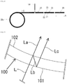
- a translucent cover member 100 comprises an incident surface 101 to which a display light L is incident, and an emission surface 102 from which the display light L is emitted, as shown in Fig. 9 .
- the display light L splits into an emitted light La that is to be emitted at the emission surface 102, and a reflected light Lb that is to be reflected at the emission surface 102.
- the reflected light Lb is reflected again at the incident surface 101, and this reflected light Lc travels toward a projection member so as to be parallel to the emitted light La.
- the virtual image may become a double image due to the emitted light La and the reflected light Lc that were split from the display light L reaching the viewer.
- the present invention has been made in view of the circumstance described above. Accordingly, it is an object of the present invention to provide a translucent cover member for a head-up display device and a head-up display device that suppress a virtual image from becoming a double image.
- a translucent cover member for a head-up display device is a translucent cover member for a head-up display device that covers an opening of a housing and transmits a display light, comprising a base material made of a translucent resin, and a moth eye layer that is formed on the display light incidence side of the base material and suppresses reflection of light.
- a head-up display device is a head-up display device comprising the translucent cover member for a head-up display, the housing having the opening, and a display that displays a virtual image by emitting the display light onto a projection member, in which the translucent cover member for a head-up display device has a display luminance reduction suppressing axis, and the display luminance reduction suppressing axis is set in a direction along a virtual image viewing direction.
- a virtual image is suppressed from becoming a double image.
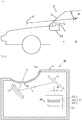
- a head-up display device 10 is arranged in a dashboard of a vehicle 2.
- the head-up display device 10 generates a display light L representing vehicle information, and emits the generated display light L toward a windshield 3 that is one example of a projection member.
- This display light L is reflected by the windshield 3 and reaches a viewer (for example, a driver of a vehicle) 4.
- the viewer 4 is able to see a virtual image V representing vehicle information formed in front of the windshield 3.
- the head-up display device 10 comprises a flat mirror 11, a concave mirror 12, a housing 13, a display 30, a transparent screen 15, and a translucent cover member 20, as shown in Fig. 2 .
- the housing 13 is made of light-blocking resin and is formed in a rectangular parallelepiped box shape. Various components of the head-up display device 10 are housed inside the housing 13. An opening 13a, which is a through-hole through which the display light L passes, is formed in the housing 13.
- the display 30 emits the display light L representing vehicle information.
- the display 30 comprises a backlight light source 31 that irradiates a light, and a liquid crystal panel 32 that receives the light from the backlight light source 31 and emits the display light L.
- the liquid crystal panel 32 comprises a liquid crystal layer 32a, a first polarizer 32b, and a second polarizer 32c.
- the first polarizer 32b, the liquid crystal layer 32a, and the second polarizer 32c are laminated in this order from the incidence side of the light from the backlight light source 31.
- the first polarizer 32b is positioned on the back side of the liquid crystal layer 32a, and emits only light in a vibration direction along its own transmission axis, of the light incident from the backlight light source 31, to the liquid crystal layer 32a side.
- the liquid crystal layer 32a is a layer within which liquid crystal is sealed, and causes the vibration direction of light to change on the basis of an instruction from a control unit, not shown.
- the liquid crystal layer 32a is positioned between the first polarizer 32b and a second polarizer 32c.
- the second polarizer 32c is positioned on the front side of the liquid crystal layer 32a, and emits, as the display light L, only light in a vibration direction along its own transmission axis, of the light from the liquid crystal layer 32a.
- the transmission axes of both polarizers 22b and 22c are set to a direction orthogonal to each other as viewed from the front of the display 30.
- the liquid crystal layer 32a causes the vibration direction of the light to align with the transmission axis of the second polarizer 32c by rotating the vibration direction of the light 90 degrees at a predetermined pixel of the liquid crystal panel 32.
- the light passes through the second polarizer 32c at the predetermined pixel.
- the liquid crystal layer 32a causes the vibration direction of the light to align with an absorption axis that is orthogonal to the transmission axis of the second polarizer 32c by not allowing the vibration direction of the light to rotate at a predetermined pixel of the liquid crystal panel 32.
- the light does not pass through the second polarizer 32c but is absorbed at the predetermined pixel.
- the display light L representing a display image can be caused to be emitted from the liquid crystal panel 32 by the transmission or absorption of a light M being controlled for each pixel of the liquid crystal panel 32.
- the transparent screen 15 receives the display light L from the display 30 and forms an image D, and emits the display light L representing this image D to the flat mirror 11.
- the flat mirror 11 reflects the display light L representing the image D from the transparent screen 15 toward the concave mirror 12.
- the concave mirror 12 reflects the display light L from the flat mirror 11 toward the windshield 3. This display light L passes through the translucent cover member 20 of the housing 13 and reaches the windshield 3.
- the translucent cover member 20 is provided so as to block the opening 13a of the housing 13, as shown in Fig. 2 .
- the translucent cover member 20 is formed in a curved plate shape in order to suppress outside light that has reached the translucent cover member 20 from being reflected toward the viewer 4.
- the translucent cover member 20 is flexible so as to be able to be wound around the outer circumference of a third winding shaft 28c that will be described later, as shown in Fig. 8 .
- a predetermined optical anisotropy occurs in the process of manufacturing the translucent cover member 20 by stretching the base material 21 and winding the base material 21 around winding shafts 28a to 28c. Therefore, depending on the orientation of the translucent cover member 20, the display luminance of the virtual image V decreases when the viewer 4 views the virtual image V through polarized sunglasses 8.
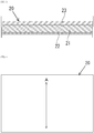
- the translucent cover member 20 is disposed at an orientation in which the display luminance of the virtual image V will not decrease when the viewer 4 views the virtual image V through polarized sunglasses 8. More specifically, the translucent cover member 20 has a display luminance reduction suppressing axis A, as shown in Fig. 4 .
- the translucent cover member 20 is disposed at the opening 13a of the housing 13 such that this display luminance reduction suppressing axis A is along a virtual image viewing direction B (see Fig. 1 ) that is a direction from which viewer 4 views the virtual image V formed in front of the windshield 3.
- the translucent cover member 20 is disposed at the opening 13a of the housing 13 such that a direction C in which the translucent cover member 20 is unwound from a state wound around the third winding shaft 28c is along the virtual image viewing direction B, as shown in Fig. 8 that will be referred to later.
- the translucent cover member 20 is disposed in the housing 13 such that a longitudinal stretching direction H when the base material 21 is stretched in the longitudinal direction is along the virtual image viewing direction B, as shown in Fig. 5 that will be referred to later.
- a decrease in the display luminance of the virtual image V is suppressed when the viewer 4 views the virtual image V through polarized sunglasses 8.
- the translucent cover member 20 comprises the base material 21, the moth eye layer 22, and the hard coat layer 23, as shown in Fig. 3 .
- the base material 21 is made of an optically transparent polycarbonate resin.
- Polycarbonate resin has higher flexibility than acrylic resin.
- the moth eye layer 22 is made of, for example, an ultraviolet curable resin having a fine uneven structure of nanometer size and has a reflection suppressing characteristic. This reflection suppressing characteristic suppresses the virtual image V from becoming a double image.
- the hard coat layer 23 protects the base material 21 from becoming scratched.
- the hard coat layer 23 is made of an optically transparent resin.
- the hard coat layer 23 is positioned on the display light L emission side of the base material 21, that is, on the front side of the base material 21.
- the base material 21 is manufactured, and this base material 21 is wound around the first winding shaft 28a.
- the longitudinal stretching direction H is along the longitudinal direction of the sheet material 21a
- the transverse stretching direction W is along the transverse direction of the sheet material 21a.
- the translucent cover member 20 is manufactured from the base material 21 by a manufacturing apparatus, as shown in Fig. 6 to Fig. 8 .
- This manufacturing apparatus comprises a first resin supply portion 51a and a first ultraviolet light emitting portion 55a, shown in Fig. 6 , a second resin supply portion 51b, a roll mold 52, a press roller 53, a peeling roller 54, and a second ultraviolet light emitting portion 55b, shown in Fig. 7 , and a cutter 58 shown in Fig. 8 .
- the second resin supply portion 51b, the roll mold 52, the press roller 53, and the peeling roller 54 form the moth eye layer 22 on the back surface of the base material 21. More specifically, the second resin supply portion 51b ejects an ultraviolet curable resin 22a onto the back surface of the intermediate product 26 that has been unwound from the second winding shaft 28b.
- the roll mold 52 has an uneven portion, not shown, for forming the uneven structure of the moth eye layer 22, on the outer peripheral surface of the roll mold 52.
- the press roller 53 is positioned between the second resin supply portion 51b and the roll mold 52, and causes the outer peripheral surface of the roll mold 52 to closely contact the resin 22a formed on the back surface of the base material 21, by applying tension to the base material 21.
- the cutter 58 forms the translucent cover member 20 into a desired size by cutting the translucent cover member 20 that has been unwound from the third winding shaft 28c. This completes the manufacture of the translucent cover member 20.
- the translucent cover member 20 comprises the base material 21, the moth eye layer 22, and the hard coat layer 23, but the hard coat layer 23 may be omitted.
- the base material 21 is made of polycarbonate resin, but the base material 21 may be made of another resin such as acrylic resin.
- the manufacturing method of the translucent cover member 20 in the embodiment described above can be modified as appropriate.
- the moth eye layer 22 may be affixed as a film to the back surface of the base material 21.
- the moth eye layer 22 and the hard coat layer 23 are made of ultraviolet curable resin, but the moth eye layer 22 and the hard coat layer 23 may be made of thermosetting resin.
- the moth eye layer 22 and the hard coat layer 23 may be fixed to the base material 21 via an adhesive.
- the head-up display device 10 in the embodiment described above is a head-up display device to be mounted in a vehicle, but is not limited to a head-up display device to be mounted in a vehicle, and may be a head-up display device to be mounted in a conveyance such as an aircraft or a watercraft. Also, the projection member is not limited to a windshield, and may be a dedicated combiner.
- the present invention is applicable to a head-up display device or the like to be mounted in a vehicle.
Landscapes
- Physics & Mathematics (AREA)
- General Physics & Mathematics (AREA)
- Optics & Photonics (AREA)
- Engineering & Computer Science (AREA)
- Chemical & Material Sciences (AREA)
- Combustion & Propulsion (AREA)
- Transportation (AREA)
- Mechanical Engineering (AREA)
- Instrument Panels (AREA)
- Microelectronics & Electronic Packaging (AREA)
Description
- The present invention relates to a translucent cover member for a head-up display device and a head-up display device.
- Conventionally, a head-up display device is known that comprises a display that emits a display light, and an optical system comprising a concave mirror that guides the display light to a projection member such as a windshield, and the like. A viewer can receive the display light reflected on the projection member and view a virtual image corresponding the display light. This head-up display device comprises a housing that has an opening through which display light that has passed through the optical system passes, and that houses the display and the optical system and the like, and a translucent cover member that covers this opening and transmits the display light that has passed through the optical system, as described in Patent Literature 1, for example.
- Patent Literature 1: Japanese Patent Application Publication No.
2016-061978 - In this head-up display device, a
translucent cover member 100 comprises anincident surface 101 to which a display light L is incident, and anemission surface 102 from which the display light L is emitted, as shown inFig. 9 . After the display light L is incident totranslucent cover member 100 from theincident surface 101, the display light L splits into an emitted light La that is to be emitted at theemission surface 102, and a reflected light Lb that is to be reflected at theemission surface 102. Then, the reflected light Lb is reflected again at theincident surface 101, and this reflected light Lc travels toward a projection member so as to be parallel to the emitted light La. In this way, it is possible that the virtual image may become a double image due to the emitted light La and the reflected light Lc that were split from the display light L reaching the viewer. - The present invention has been made in view of the circumstance described above. Accordingly, it is an object of the present invention to provide a translucent cover member for a head-up display device and a head-up display device that suppress a virtual image from becoming a double image.
- To achieve the above object, a translucent cover member for a head-up display device according to a first aspect of the present invention is a translucent cover member for a head-up display device that covers an opening of a housing and transmits a display light, comprising a base material made of a translucent resin, and a moth eye layer that is formed on the display light incidence side of the base material and suppresses reflection of light.
- To achieve the above object, a head-up display device according to a second aspect of the present invention is a head-up display device comprising the translucent cover member for a head-up display, the housing having the opening, and a display that displays a virtual image by emitting the display light onto a projection member, in which the translucent cover member for a head-up display device has a display luminance reduction suppressing axis, and the display luminance reduction suppressing axis is set in a direction along a virtual image viewing direction.
- According to the present invention, a virtual image is suppressed from becoming a double image.
-
-
Fig. 1 is a schematic diagram of a vehicle equipped with a head-up display device according to one embodiment of the present invention. -
Fig. 2 is a schematic view showing a configuration of a head-up display device according to one embodiment of the present invention. -
Fig. 3 is a sectional view of a translucent cover member according to one embodiment of the present invention. -
Fig. 4 is a front view of a translucent cover member according to one embodiment of the present invention. -
Fig. 5 is a schematic view of when a base material according to one embodiment of the present invention is manufactured. -
Fig. 6 is a schematic view of when a hard coat layer is laminated to a base material according to one embodiment of the present invention. -
Fig. 7 is a schematic view of when a moth eye layer is laminated to a base material according to one embodiment of the present invention. -
Fig. 8 is a schematic view of when an intermediate product in which a base material, a moth eye layer, and a hard coat layer according to one embodiment of the present invention have been laminated is cut. -
Fig. 9 is a sectional view of a translucent cover member according to background art. - One embodiment of a head-up display device comprising a translucent cover member for a head-up display device according to the present invention will be described with reference to the drawings.
- As shown in
Fig. 1 , a head-updisplay device 10 is arranged in a dashboard of avehicle 2. The head-updisplay device 10 generates a display light L representing vehicle information, and emits the generated display light L toward awindshield 3 that is one example of a projection member. This display light L is reflected by thewindshield 3 and reaches a viewer (for example, a driver of a vehicle) 4. As a result, the viewer 4 is able to see a virtual image V representing vehicle information formed in front of thewindshield 3. - The head-up
display device 10 comprises aflat mirror 11, aconcave mirror 12, ahousing 13, adisplay 30, atransparent screen 15, and atranslucent cover member 20, as shown inFig. 2 . - The
housing 13 is made of light-blocking resin and is formed in a rectangular parallelepiped box shape. Various components of the head-updisplay device 10 are housed inside thehousing 13. An opening 13a, which is a through-hole through which the display light L passes, is formed in thehousing 13. - The
display 30 emits the display light L representing vehicle information. Thedisplay 30 comprises abacklight light source 31 that irradiates a light, and aliquid crystal panel 32 that receives the light from thebacklight light source 31 and emits the display light L. Theliquid crystal panel 32 comprises aliquid crystal layer 32a, afirst polarizer 32b, and asecond polarizer 32c. Thefirst polarizer 32b, theliquid crystal layer 32a, and thesecond polarizer 32c are laminated in this order from the incidence side of the light from thebacklight light source 31. - The
first polarizer 32b is positioned on the back side of theliquid crystal layer 32a, and emits only light in a vibration direction along its own transmission axis, of the light incident from thebacklight light source 31, to theliquid crystal layer 32a side. - The
liquid crystal layer 32a is a layer within which liquid crystal is sealed, and causes the vibration direction of light to change on the basis of an instruction from a control unit, not shown. Theliquid crystal layer 32a is positioned between thefirst polarizer 32b and asecond polarizer 32c. - The
second polarizer 32c is positioned on the front side of theliquid crystal layer 32a, and emits, as the display light L, only light in a vibration direction along its own transmission axis, of the light from theliquid crystal layer 32a. For example, the transmission axes of both polarizers 22b and 22c are set to a direction orthogonal to each other as viewed from the front of thedisplay 30. In this case, theliquid crystal layer 32a causes the vibration direction of the light to align with the transmission axis of thesecond polarizer 32c by rotating the vibration direction of the light 90 degrees at a predetermined pixel of theliquid crystal panel 32. As a result, the light passes through thesecond polarizer 32c at the predetermined pixel. Also, theliquid crystal layer 32a causes the vibration direction of the light to align with an absorption axis that is orthogonal to the transmission axis of thesecond polarizer 32c by not allowing the vibration direction of the light to rotate at a predetermined pixel of theliquid crystal panel 32. As a result, the light does not pass through thesecond polarizer 32c but is absorbed at the predetermined pixel. In this way, the display light L representing a display image can be caused to be emitted from theliquid crystal panel 32 by the transmission or absorption of a light M being controlled for each pixel of theliquid crystal panel 32. - The
transparent screen 15 receives the display light L from thedisplay 30 and forms an image D, and emits the display light L representing this image D to theflat mirror 11. Theflat mirror 11 reflects the display light L representing the image D from thetransparent screen 15 toward theconcave mirror 12. Theconcave mirror 12 reflects the display light L from theflat mirror 11 toward thewindshield 3. This display light L passes through thetranslucent cover member 20 of thehousing 13 and reaches thewindshield 3. - The
translucent cover member 20 is provided so as to block the opening 13a of thehousing 13, as shown inFig. 2 . Thetranslucent cover member 20 is formed in a curved plate shape in order to suppress outside light that has reached thetranslucent cover member 20 from being reflected toward the viewer 4. Thetranslucent cover member 20 is flexible so as to be able to be wound around the outer circumference of a third windingshaft 28c that will be described later, as shown inFig. 8 . - Here, a predetermined optical anisotropy occurs in the process of manufacturing the
translucent cover member 20 by stretching thebase material 21 and winding thebase material 21 around windingshafts 28a to 28c. Therefore, depending on the orientation of thetranslucent cover member 20, the display luminance of the virtual image V decreases when the viewer 4 views the virtual image V through polarizedsunglasses 8. In this regard, in the present embodiment, thetranslucent cover member 20 is disposed at an orientation in which the display luminance of the virtual image V will not decrease when the viewer 4 views the virtual image V through polarizedsunglasses 8. More specifically, thetranslucent cover member 20 has a display luminance reduction suppressing axis A, as shown inFig. 4 . Thetranslucent cover member 20 is disposed at theopening 13a of thehousing 13 such that this display luminance reduction suppressing axis A is along a virtual image viewing direction B (seeFig. 1 ) that is a direction from which viewer 4 views the virtual image V formed in front of thewindshield 3. In other words, thetranslucent cover member 20 is disposed at theopening 13a of thehousing 13 such that a direction C in which thetranslucent cover member 20 is unwound from a state wound around the third windingshaft 28c is along the virtual image viewing direction B, as shown inFig. 8 that will be referred to later. Furthermore, in other words, thetranslucent cover member 20 is disposed in thehousing 13 such that a longitudinal stretching direction H when thebase material 21 is stretched in the longitudinal direction is along the virtual image viewing direction B, as shown inFig. 5 that will be referred to later. As a result, a decrease in the display luminance of the virtual image V is suppressed when the viewer 4 views the virtual image V throughpolarized sunglasses 8. - More specifically, the
translucent cover member 20 comprises thebase material 21, themoth eye layer 22, and thehard coat layer 23, as shown inFig. 3 . - The
base material 21 is made of an optically transparent polycarbonate resin. Polycarbonate resin has higher flexibility than acrylic resin. - The
moth eye layer 22 is made of, for example, an ultraviolet curable resin having a fine uneven structure of nanometer size and has a reflection suppressing characteristic. This reflection suppressing characteristic suppresses the virtual image V from becoming a double image. - The
hard coat layer 23 protects thebase material 21 from becoming scratched. Thehard coat layer 23 is made of an optically transparent resin. Thehard coat layer 23 is positioned on the display light L emission side of thebase material 21, that is, on the front side of thebase material 21. - As an example, the thickness of the
base material 21 is set at 390 µm, the thickness of themoth eye layer 22 is set at 4 µm, and the thickness of thehard coat layer 23 is set at 10 µm. - Next, a manufacturing method of the
translucent cover member 20 will be described. - First, a
sheet material 21a is formed by a molten polycarbonate resin, which is the raw material of thebase material 21, being stretched, as shown inFig. 5 . Thesheet material 21a has a rectangular shape. Thesheet material 21a is sequentially fed toward the first windingshaft 28a by a plurality ofrollers 29a to 29f in the longitudinal direction of thesheet material 21a. Thesheet material 21a is stretched by a molten two-axis stretching method that is well-known technology. More specifically, thesheet material 21a is stretched in the longitudinal stretching direction H between a pair ofrollers sheet material 21a is stretched in a transverse stretching direction W between a pair ofrollers base material 21 is manufactured, and thisbase material 21 is wound around the first windingshaft 28a. The longitudinal stretching direction H is along the longitudinal direction of thesheet material 21a, and the transverse stretching direction W is along the transverse direction of thesheet material 21a. - The
translucent cover member 20 is manufactured from thebase material 21 by a manufacturing apparatus, as shown inFig. 6 to Fig. 8 . This manufacturing apparatus comprises a firstresin supply portion 51a and a first ultravioletlight emitting portion 55a, shown inFig. 6 , a secondresin supply portion 51b, aroll mold 52, apress roller 53, a peelingroller 54, and a second ultravioletlight emitting portion 55b, shown inFig. 7 , and acutter 58 shown inFig. 8 . - As shown in
Fig. 6 , the firstresin supply portion 51a and the first ultravioletlight emitting portion 55a form thehard coat layer 23 on the front surface of thebase material 21. More specifically, the firstresin supply portion 51a ejects an ultravioletcurable resin 23a serving as the raw material of thehard coat layer 23 onto the front surface of thebase material 21 that has been unwound from the first windingshaft 28a. The first ultravioletlight emitting portion 55a irradiates ultraviolet light at the suppliedresin 23a, thereby curing theresin 23a. As a result, anintermediate product 26 comprising thehard coat layer 23 and thebase material 21 is manufactured. Theintermediate product 26 is wound around the outer circumference of the second windingshaft 28b. - As shown in
Fig. 7 , the secondresin supply portion 51b, theroll mold 52, thepress roller 53, and the peelingroller 54 form themoth eye layer 22 on the back surface of thebase material 21. More specifically, the secondresin supply portion 51b ejects an ultravioletcurable resin 22a onto the back surface of theintermediate product 26 that has been unwound from the second windingshaft 28b. Theroll mold 52 has an uneven portion, not shown, for forming the uneven structure of themoth eye layer 22, on the outer peripheral surface of theroll mold 52. Thepress roller 53 is positioned between the secondresin supply portion 51b and theroll mold 52, and causes the outer peripheral surface of theroll mold 52 to closely contact theresin 22a formed on the back surface of thebase material 21, by applying tension to thebase material 21. As a result, the uneven portion, not shown, that is described above, of theroll mold 52 is transferred to theresin 22a. The second ultravioletlight emitting portion 55b irradiates ultraviolet light at theresin 22a in which the uneven structure is formed, thereby curing theresin 22a. This curedresin 22a is themoth eye layer 22. As a result,translucent cover member 20 comprising themoth eye layer 22, thehard coat layer 23, and thebase material 21 is manufactured. The peelingroller 54 causes thetranslucent cover member 20 to peel away from theroll mold 52, by applying tension to thetranslucent cover member 20 from theroll mold 52. Also, thetranslucent cover member 20 is wound around the outer circumference of the cylindrical third windingshaft 28c. - As shown in
Fig. 8 , thecutter 58 forms thetranslucent cover member 20 into a desired size by cutting thetranslucent cover member 20 that has been unwound from the third windingshaft 28c. This completes the manufacture of thetranslucent cover member 20. - According to the embodiment described above, the following effects are obtained.
- (1) The
translucent cover member 20 covers theopening 13a of thehousing 13, and the display light L passes therethrough. Thetranslucent cover member 20 comprises thebase material 21 made of translucent resin, and themoth eye layer 22 that is formed on the display light L incidence side of thebase material 21 and suppresses the reflection of light.
According to this configuration, the display light L is suppressed by themoth eye layer 22 from being reflected. Therefore, the virtual image V is suppressed from becoming a double image.
Also, if a moth eye film is affixed to the back surface of a translucent cover member, wrinkles appear when the moth eye film is affixed or due to deterioration with aging, and as a result, the display quality of the virtual image deteriorates, which is problematic. With this in mind, in the embodiment described above, themoth eye layer 22 is not a moth eye film, but is made of ultraviolet curable resin. Therefore, this problem will not occur, so it is possible to suppress deterioration of the display quality of the virtual image. - (2) The
translucent cover member 20 further comprises thehard coat layer 23 that is formed on the display light L emission side of thebase material 21, and protects thebase material 21. Also, thebase material 21 is made of polycarbonate resin.
According to this configuration, thebase material 21 is made of polycarbonate resin that is more flexible than acrylic resin. Therefore, when manufacturing thetranslucent cover member 20, thehard coat layer 23 and themoth eye layer 22 can be formed while feeding thebase material 21 with the windingshafts 28a to 28c. As a result, the manufacturing efficiency of thetranslucent cover member 20 can be improved.
Also, thebase material 21 is made of polycarbonate resin that is softer than acrylic resin, but damage to thebase material 21 is suppressed by thehard coat layer 23 being formed. - (3) The head-up
display device 10 comprises thetranslucent cover member 20, thehousing 13 having theopening 13a, thedisplay 30 that emits the display light L, and theflat mirror 11 and theconcave mirror 12 that comprise the optical system that displays the virtual image V by guiding the display light L from thedisplay 30 to thewindshield 3. Thetranslucent cover member 20 has the display luminance reduction suppressing axis A, and this display luminance reduction suppressing axis A is set in a direction along the virtual image viewing direction B. According to this configuration, the display luminance of the virtual image V will not decrease, so deterioration of the display quality of the virtual image is suppressed. - (4) The
translucent cover member 20 is disposed in thehousing 13 such that the direction C in which thetranslucent cover member 20 is unwound from a state wound around the third windingshaft 28c is along the virtual image viewing direction B.
According to this configuration, it is possible to suppress a decrease in the display luminance of the virtual image V when the viewer 4 views the virtual image V throughpolarized sunglasses 8. As a result, deterioration of the display quality of the virtual image V is suppressed. - (5) The
translucent cover member 20 is disposed in thehousing 13 such that the longitudinal stretching direction H when thebase material 21 is stretched in the longitudinal direction by the molten two-axis stretching method is along the virtual image viewing direction B.
According to this configuration, it is possible to suppress a decrease in the display luminance of the virtual image V when the viewer 4 views the virtual image V throughpolarized sunglasses 8. As a result, deterioration of the display quality of the virtual image V is suppressed. - Note that the embodiment described above can be carried out in the following modes that have been appropriately modified.
- In the embodiment described above, the
translucent cover member 20 comprises thebase material 21, themoth eye layer 22, and thehard coat layer 23, but thehard coat layer 23 may be omitted. - In the embodiment described above, the
base material 21 is made of polycarbonate resin, but thebase material 21 may be made of another resin such as acrylic resin. - The manufacturing method of the
translucent cover member 20 in the embodiment described above can be modified as appropriate. For example, themoth eye layer 22 may be affixed as a film to the back surface of thebase material 21. Also, themoth eye layer 22 and thehard coat layer 23 are made of ultraviolet curable resin, but themoth eye layer 22 and thehard coat layer 23 may be made of thermosetting resin. Themoth eye layer 22 and thehard coat layer 23 may be fixed to thebase material 21 via an adhesive. - The head-up
display device 10 in the embodiment described above is a head-up display device to be mounted in a vehicle, but is not limited to a head-up display device to be mounted in a vehicle, and may be a head-up display device to be mounted in a conveyance such as an aircraft or a watercraft. Also, the projection member is not limited to a windshield, and may be a dedicated combiner. - The present invention is applicable to a head-up display device or the like to be mounted in a vehicle.
-
- 3
- Windshield
- 8
- Polarized sunglasses
- 10
- Head-up display device
- 11
- Flat mirror
- 12
- Curved mirror
- 13
- Housing
- 13a
- Opening
- 15
- Transparent screen
- 20
- Translucent cover member
- 21
- Base material
- 21a
- Sheet material
- 22
- Moth eye layer
- 23
- Hard coat layer
- 26
- Intermediate product
- 28a
- First winding shaft
- 28b
- Second winding shaft
- 28c
- Third winding shaft
- 29a to 29f
- Roller
- 30
- Display
- 31
- Backlight light source
- 32
- Liquid crystal panel
- 32a
- Liquid crystal layer
- 32b
- First polarizer
- 32c
- Second polarizer
- 51a
- First resin supply portion
- 51b
- Second resin supply portion
- 52
- Roll mold
- 53
- Press roller
- 54
- Peeling roller
- 55a
- First ultraviolet light emitting portion
- 55b
- Second ultraviolet light emitting portion
- 58
- Cutter
Claims (5)
- A translucent cover member for a head-up display device, which covers an opening of a housing and transmits a display light, comprising:a base material made of a translucent resin; anda moth eye layer that is formed on the display light incidence side of the base material and suppresses reflection of light.
- The translucent cover member for a head-up display device according to claim 1, comprising:a hard coat layer that is formed on the display light emission side of the base material and protects the base material,wherein the base material is made of a polycarbonate resin.
- A head-up display device provided with the translucent cover member for a head-up display device according to claim 1 or 2,
the housing having the opening,
and a display that displays a virtual image by emitting the display light onto a projection member, wherein
the translucent cover member for a head-up display device has a display luminance reduction suppressing axis, and the display luminance reduction suppressing axis is set in a direction along a virtual image viewing direction. - The head-up display device according to claim 3, wherein
the head-up display is mounted in a vehicle, and
the translucent cover member for a head-up display device is disposed in the housing such that a direction in which the translucent cover member for a head-up display device is unwound from a state wound around a winding shaft is along the virtual image viewing direction. - The head-up display device according to claim 3, wherein
the head-up display is mounted in a vehicle, and
the translucent cover member for a head-up display device is disposed in the housing such that a longitudinal stretching direction in which the base material is stretched in a longitudinal direction is along the virtual image viewing direction.
Applications Claiming Priority (2)
| Application Number | Priority Date | Filing Date | Title |
|---|---|---|---|
| JP2016183914 | 2016-09-21 | ||
| PCT/JP2017/032807 WO2018056111A1 (en) | 2016-09-21 | 2017-09-12 | Translucent cover member for head-up display device and head-up display device |
Publications (3)
| Publication Number | Publication Date |
|---|---|
| EP3518021A1 true EP3518021A1 (en) | 2019-07-31 |
| EP3518021A4 EP3518021A4 (en) | 2020-05-06 |
| EP3518021B1 EP3518021B1 (en) | 2021-06-09 |
Family
ID=61690973
Family Applications (1)
| Application Number | Title | Priority Date | Filing Date |
|---|---|---|---|
| EP17852888.1A Active EP3518021B1 (en) | 2016-09-21 | 2017-09-12 | Head-up display device |
Country Status (5)
| Country | Link |
|---|---|
| US (1) | US20190212553A1 (en) |
| EP (1) | EP3518021B1 (en) |
| JP (1) | JP6665943B2 (en) |
| CN (1) | CN109716205B (en) |
| WO (1) | WO2018056111A1 (en) |
Families Citing this family (5)
| Publication number | Priority date | Publication date | Assignee | Title |
|---|---|---|---|---|
| JP7483355B2 (en) * | 2019-11-27 | 2024-05-15 | 京セラ株式会社 | Head-up display, head-up display system and mobile body |
| US12296684B2 (en) * | 2020-09-22 | 2025-05-13 | Yazaki North America, Inc. | Head-up display unit for vehicle including flocking and methods for applying flocking onto same |
| JPWO2023120291A1 (en) * | 2021-12-21 | 2023-06-29 | ||
| JP7833783B2 (en) * | 2022-09-20 | 2026-03-23 | 東山フイルム株式会社 | Head-up display device and cover member for head-up display device |
| JP2025012233A (en) * | 2023-07-13 | 2025-01-24 | 矢崎総業株式会社 | Head-up display device |
Family Cites Families (14)
| Publication number | Priority date | Publication date | Assignee | Title |
|---|---|---|---|---|
| JPH0626435Y2 (en) * | 1987-04-03 | 1994-07-20 | 日産自動車株式会社 | Vehicle display |
| US5237455A (en) * | 1991-12-06 | 1993-08-17 | Delco Electronics Corporation | Optical combiner with integral support arm |
| JP2003222701A (en) * | 2002-01-29 | 2003-08-08 | Seiko Epson Corp | Optical component and method of manufacturing the same |
| JP2007069771A (en) * | 2005-09-07 | 2007-03-22 | Denso Corp | Head-up display device for vehicle |
| US7864431B2 (en) * | 2008-06-04 | 2011-01-04 | Centre Luxembourgeois De Recherches Pour Le Verre Et La Ceramique S.A. (C.R.V.C.) | Windshield for use with head-up display and/or method of making the same |
| EP2395496A4 (en) * | 2009-02-06 | 2012-09-19 | Sharp Kk | Display device |
| WO2012042793A1 (en) * | 2010-10-01 | 2012-04-05 | パナソニック株式会社 | See-through display device and vehicle having see-through display device mounted thereon |
| DE102011014145A1 (en) * | 2010-12-23 | 2012-06-28 | Continental Automotive Gmbh | Head-up display for a motor vehicle |
| JP6131766B2 (en) * | 2013-08-06 | 2017-05-24 | 株式会社デンソー | Head-up display device for vehicle |
| JP6247952B2 (en) * | 2014-02-13 | 2017-12-13 | 株式会社 オルタステクノロジー | Head-up display device |
| IL235642B (en) * | 2014-11-11 | 2021-08-31 | Lumus Ltd | Compact head-mounted display system protected by a hyperfine structure |
| JP6459440B2 (en) * | 2014-11-27 | 2019-01-30 | 日本精機株式会社 | Head-up display device |
| JP6507684B2 (en) * | 2015-02-05 | 2019-05-08 | 日本精機株式会社 | Display device |
| US10302937B2 (en) * | 2015-08-07 | 2019-05-28 | GM Global Technology Operations LLC | Head-up display system and device |
-
2017
- 2017-09-12 WO PCT/JP2017/032807 patent/WO2018056111A1/en not_active Ceased
- 2017-09-12 JP JP2018540982A patent/JP6665943B2/en active Active
- 2017-09-12 EP EP17852888.1A patent/EP3518021B1/en active Active
- 2017-09-12 CN CN201780057808.5A patent/CN109716205B/en active Active
- 2017-09-12 US US16/334,271 patent/US20190212553A1/en not_active Abandoned
Also Published As
| Publication number | Publication date |
|---|---|
| JPWO2018056111A1 (en) | 2019-08-08 |
| CN109716205A (en) | 2019-05-03 |
| WO2018056111A1 (en) | 2018-03-29 |
| EP3518021A4 (en) | 2020-05-06 |
| CN109716205B (en) | 2021-07-27 |
| EP3518021B1 (en) | 2021-06-09 |
| US20190212553A1 (en) | 2019-07-11 |
| JP6665943B2 (en) | 2020-03-13 |
Similar Documents
| Publication | Publication Date | Title |
|---|---|---|
| US20190212553A1 (en) | Translucent cover member for head-up display device and head-up display device | |
| CN101925846B (en) | Optical thin film laminate roll and its manufacturing method and system | |
| KR101538823B1 (en) | Manufacturing method of liquid crystal display device | |
| JP4525808B2 (en) | Stereoscopic image display device and manufacturing method thereof | |
| JP4591591B2 (en) | Stereoscopic image display device and manufacturing method thereof | |
| JP4582219B2 (en) | Stereoscopic image display device and manufacturing method thereof | |
| TWI551918B (en) | A manufacturing method of a liquid crystal display element, and a manufacturing system of a liquid crystal display device | |
| JP5815492B2 (en) | Optical film, polarizing plate, image display device, and 3D image display system | |
| JP2015021976A (en) | Optical film transfer body and method for producing optical film transfer body | |
| WO2011162271A1 (en) | Method and system for producing liquid crystal panel | |
| TWI599487B (en) | A method of manufacturing a laminated optical film, and a method of manufacturing a liquid crystal panel | |
| JP2010032675A (en) | Method for manufacturing stereoscopic image display, and stereoscopic image display | |
| JP2010032674A (en) | Stereoscopic image display apparatus and manufacturing method therefor | |
| JP2014059456A (en) | Transfer body for optical film, optical film, and image display device | |
| JP6008758B2 (en) | Intermediate product of optical film, optical film, image display device, and method of manufacturing optical film | |
| CN102264547A (en) | Multilayer film depicting colored two-dimensional images visible only through polarizing filters and process for making the film | |
| JP2017015845A (en) | Optical film, circularly polarizing plate, and organic electroluminescence display device | |
| WO2013186818A1 (en) | Display device and method for producing same | |
| JP6107236B2 (en) | Optical film manufacturing method, optical film, optical film substrate and image display device | |
| JP4977263B2 (en) | Liquid crystal panel manufacturing method and manufacturing system | |
| JP2015052693A (en) | Process for producing pattern retardation film and protective film | |
| JP2018141907A (en) | Liquid crystal display | |
| JP2016188961A (en) | Production method of optical film | |
| JP2015184436A (en) | Patterned retardation film, optical film, and image display device |
Legal Events
| Date | Code | Title | Description |
|---|---|---|---|
| STAA | Information on the status of an ep patent application or granted ep patent |
Free format text: STATUS: THE INTERNATIONAL PUBLICATION HAS BEEN MADE |
|
| PUAI | Public reference made under article 153(3) epc to a published international application that has entered the european phase |
Free format text: ORIGINAL CODE: 0009012 |
|
| STAA | Information on the status of an ep patent application or granted ep patent |
Free format text: STATUS: REQUEST FOR EXAMINATION WAS MADE |
|
| 17P | Request for examination filed |
Effective date: 20190311 |
|
| AK | Designated contracting states |
Kind code of ref document: A1 Designated state(s): AL AT BE BG CH CY CZ DE DK EE ES FI FR GB GR HR HU IE IS IT LI LT LU LV MC MK MT NL NO PL PT RO RS SE SI SK SM TR |
|
| AX | Request for extension of the european patent |
Extension state: BA ME |
|
| DAV | Request for validation of the european patent (deleted) | ||
| DAX | Request for extension of the european patent (deleted) | ||
| A4 | Supplementary search report drawn up and despatched |
Effective date: 20200402 |
|
| RIC1 | Information provided on ipc code assigned before grant |
Ipc: G02B 27/01 20060101AFI20200328BHEP Ipc: G02B 1/118 20150101ALI20200328BHEP Ipc: B32B 17/10 20060101ALI20200328BHEP Ipc: B60K 35/00 20060101ALI20200328BHEP |
|
| GRAP | Despatch of communication of intention to grant a patent |
Free format text: ORIGINAL CODE: EPIDOSNIGR1 |
|
| STAA | Information on the status of an ep patent application or granted ep patent |
Free format text: STATUS: GRANT OF PATENT IS INTENDED |
|
| INTG | Intention to grant announced |
Effective date: 20210209 |
|
| GRAS | Grant fee paid |
Free format text: ORIGINAL CODE: EPIDOSNIGR3 |
|
| GRAA | (expected) grant |
Free format text: ORIGINAL CODE: 0009210 |
|
| STAA | Information on the status of an ep patent application or granted ep patent |
Free format text: STATUS: THE PATENT HAS BEEN GRANTED |
|
| AK | Designated contracting states |
Kind code of ref document: B1 Designated state(s): AL AT BE BG CH CY CZ DE DK EE ES FI FR GB GR HR HU IE IS IT LI LT LU LV MC MK MT NL NO PL PT RO RS SE SI SK SM TR |
|
| REG | Reference to a national code |
Ref country code: GB Ref legal event code: FG4D |
|
| REG | Reference to a national code |
Ref country code: CH Ref legal event code: EP Ref country code: AT Ref legal event code: REF Ref document number: 1400985 Country of ref document: AT Kind code of ref document: T Effective date: 20210615 |
|
| REG | Reference to a national code |
Ref country code: DE Ref legal event code: R096 Ref document number: 602017040169 Country of ref document: DE |
|
| REG | Reference to a national code |
Ref country code: IE Ref legal event code: FG4D |
|
| REG | Reference to a national code |
Ref country code: LT Ref legal event code: MG9D |
|
| PG25 | Lapsed in a contracting state [announced via postgrant information from national office to epo] |
Ref country code: HR Free format text: LAPSE BECAUSE OF FAILURE TO SUBMIT A TRANSLATION OF THE DESCRIPTION OR TO PAY THE FEE WITHIN THE PRESCRIBED TIME-LIMIT Effective date: 20210609 Ref country code: BG Free format text: LAPSE BECAUSE OF FAILURE TO SUBMIT A TRANSLATION OF THE DESCRIPTION OR TO PAY THE FEE WITHIN THE PRESCRIBED TIME-LIMIT Effective date: 20210909 Ref country code: FI Free format text: LAPSE BECAUSE OF FAILURE TO SUBMIT A TRANSLATION OF THE DESCRIPTION OR TO PAY THE FEE WITHIN THE PRESCRIBED TIME-LIMIT Effective date: 20210609 Ref country code: LT Free format text: LAPSE BECAUSE OF FAILURE TO SUBMIT A TRANSLATION OF THE DESCRIPTION OR TO PAY THE FEE WITHIN THE PRESCRIBED TIME-LIMIT Effective date: 20210609 |
|
| REG | Reference to a national code |
Ref country code: AT Ref legal event code: MK05 Ref document number: 1400985 Country of ref document: AT Kind code of ref document: T Effective date: 20210609 |
|
| REG | Reference to a national code |
Ref country code: NL Ref legal event code: MP Effective date: 20210609 |
|
| PG25 | Lapsed in a contracting state [announced via postgrant information from national office to epo] |
Ref country code: NO Free format text: LAPSE BECAUSE OF FAILURE TO SUBMIT A TRANSLATION OF THE DESCRIPTION OR TO PAY THE FEE WITHIN THE PRESCRIBED TIME-LIMIT Effective date: 20210909 Ref country code: LV Free format text: LAPSE BECAUSE OF FAILURE TO SUBMIT A TRANSLATION OF THE DESCRIPTION OR TO PAY THE FEE WITHIN THE PRESCRIBED TIME-LIMIT Effective date: 20210609 Ref country code: SE Free format text: LAPSE BECAUSE OF FAILURE TO SUBMIT A TRANSLATION OF THE DESCRIPTION OR TO PAY THE FEE WITHIN THE PRESCRIBED TIME-LIMIT Effective date: 20210609 Ref country code: RS Free format text: LAPSE BECAUSE OF FAILURE TO SUBMIT A TRANSLATION OF THE DESCRIPTION OR TO PAY THE FEE WITHIN THE PRESCRIBED TIME-LIMIT Effective date: 20210609 Ref country code: GR Free format text: LAPSE BECAUSE OF FAILURE TO SUBMIT A TRANSLATION OF THE DESCRIPTION OR TO PAY THE FEE WITHIN THE PRESCRIBED TIME-LIMIT Effective date: 20210910 |
|
| PG25 | Lapsed in a contracting state [announced via postgrant information from national office to epo] |
Ref country code: CZ Free format text: LAPSE BECAUSE OF FAILURE TO SUBMIT A TRANSLATION OF THE DESCRIPTION OR TO PAY THE FEE WITHIN THE PRESCRIBED TIME-LIMIT Effective date: 20210609 Ref country code: AT Free format text: LAPSE BECAUSE OF FAILURE TO SUBMIT A TRANSLATION OF THE DESCRIPTION OR TO PAY THE FEE WITHIN THE PRESCRIBED TIME-LIMIT Effective date: 20210609 Ref country code: RO Free format text: LAPSE BECAUSE OF FAILURE TO SUBMIT A TRANSLATION OF THE DESCRIPTION OR TO PAY THE FEE WITHIN THE PRESCRIBED TIME-LIMIT Effective date: 20210609 Ref country code: PT Free format text: LAPSE BECAUSE OF FAILURE TO SUBMIT A TRANSLATION OF THE DESCRIPTION OR TO PAY THE FEE WITHIN THE PRESCRIBED TIME-LIMIT Effective date: 20211011 Ref country code: NL Free format text: LAPSE BECAUSE OF FAILURE TO SUBMIT A TRANSLATION OF THE DESCRIPTION OR TO PAY THE FEE WITHIN THE PRESCRIBED TIME-LIMIT Effective date: 20210609 Ref country code: EE Free format text: LAPSE BECAUSE OF FAILURE TO SUBMIT A TRANSLATION OF THE DESCRIPTION OR TO PAY THE FEE WITHIN THE PRESCRIBED TIME-LIMIT Effective date: 20210609 Ref country code: ES Free format text: LAPSE BECAUSE OF FAILURE TO SUBMIT A TRANSLATION OF THE DESCRIPTION OR TO PAY THE FEE WITHIN THE PRESCRIBED TIME-LIMIT Effective date: 20210609 Ref country code: SM Free format text: LAPSE BECAUSE OF FAILURE TO SUBMIT A TRANSLATION OF THE DESCRIPTION OR TO PAY THE FEE WITHIN THE PRESCRIBED TIME-LIMIT Effective date: 20210609 Ref country code: SK Free format text: LAPSE BECAUSE OF FAILURE TO SUBMIT A TRANSLATION OF THE DESCRIPTION OR TO PAY THE FEE WITHIN THE PRESCRIBED TIME-LIMIT Effective date: 20210609 |
|
| PG25 | Lapsed in a contracting state [announced via postgrant information from national office to epo] |
Ref country code: PL Free format text: LAPSE BECAUSE OF FAILURE TO SUBMIT A TRANSLATION OF THE DESCRIPTION OR TO PAY THE FEE WITHIN THE PRESCRIBED TIME-LIMIT Effective date: 20210609 |
|
| REG | Reference to a national code |
Ref country code: DE Ref legal event code: R097 Ref document number: 602017040169 Country of ref document: DE |
|
| PLBE | No opposition filed within time limit |
Free format text: ORIGINAL CODE: 0009261 |
|
| STAA | Information on the status of an ep patent application or granted ep patent |
Free format text: STATUS: NO OPPOSITION FILED WITHIN TIME LIMIT |
|
| PG25 | Lapsed in a contracting state [announced via postgrant information from national office to epo] |
Ref country code: DK Free format text: LAPSE BECAUSE OF FAILURE TO SUBMIT A TRANSLATION OF THE DESCRIPTION OR TO PAY THE FEE WITHIN THE PRESCRIBED TIME-LIMIT Effective date: 20210609 |
|
| REG | Reference to a national code |
Ref country code: CH Ref legal event code: PL |
|
| 26N | No opposition filed |
Effective date: 20220310 |
|
| REG | Reference to a national code |
Ref country code: BE Ref legal event code: MM Effective date: 20210930 |
|
| GBPC | Gb: european patent ceased through non-payment of renewal fee |
Effective date: 20210912 |
|
| PG25 | Lapsed in a contracting state [announced via postgrant information from national office to epo] |
Ref country code: MC Free format text: LAPSE BECAUSE OF FAILURE TO SUBMIT A TRANSLATION OF THE DESCRIPTION OR TO PAY THE FEE WITHIN THE PRESCRIBED TIME-LIMIT Effective date: 20210609 Ref country code: AL Free format text: LAPSE BECAUSE OF FAILURE TO SUBMIT A TRANSLATION OF THE DESCRIPTION OR TO PAY THE FEE WITHIN THE PRESCRIBED TIME-LIMIT Effective date: 20210609 |
|
| PG25 | Lapsed in a contracting state [announced via postgrant information from national office to epo] |
Ref country code: LU Free format text: LAPSE BECAUSE OF NON-PAYMENT OF DUE FEES Effective date: 20210912 Ref country code: IT Free format text: LAPSE BECAUSE OF FAILURE TO SUBMIT A TRANSLATION OF THE DESCRIPTION OR TO PAY THE FEE WITHIN THE PRESCRIBED TIME-LIMIT Effective date: 20210609 Ref country code: IE Free format text: LAPSE BECAUSE OF NON-PAYMENT OF DUE FEES Effective date: 20210912 Ref country code: GB Free format text: LAPSE BECAUSE OF NON-PAYMENT OF DUE FEES Effective date: 20210912 Ref country code: FR Free format text: LAPSE BECAUSE OF NON-PAYMENT OF DUE FEES Effective date: 20210930 Ref country code: BE Free format text: LAPSE BECAUSE OF NON-PAYMENT OF DUE FEES Effective date: 20210930 |
|
| PG25 | Lapsed in a contracting state [announced via postgrant information from national office to epo] |
Ref country code: LI Free format text: LAPSE BECAUSE OF NON-PAYMENT OF DUE FEES Effective date: 20210930 Ref country code: CH Free format text: LAPSE BECAUSE OF NON-PAYMENT OF DUE FEES Effective date: 20210930 |
|
| PG25 | Lapsed in a contracting state [announced via postgrant information from national office to epo] |
Ref country code: CY Free format text: LAPSE BECAUSE OF FAILURE TO SUBMIT A TRANSLATION OF THE DESCRIPTION OR TO PAY THE FEE WITHIN THE PRESCRIBED TIME-LIMIT Effective date: 20210609 |
|
| PG25 | Lapsed in a contracting state [announced via postgrant information from national office to epo] |
Ref country code: HU Free format text: LAPSE BECAUSE OF FAILURE TO SUBMIT A TRANSLATION OF THE DESCRIPTION OR TO PAY THE FEE WITHIN THE PRESCRIBED TIME-LIMIT; INVALID AB INITIO Effective date: 20170912 |
|
| PG25 | Lapsed in a contracting state [announced via postgrant information from national office to epo] |
Ref country code: MK Free format text: LAPSE BECAUSE OF FAILURE TO SUBMIT A TRANSLATION OF THE DESCRIPTION OR TO PAY THE FEE WITHIN THE PRESCRIBED TIME-LIMIT Effective date: 20210609 |
|
| PG25 | Lapsed in a contracting state [announced via postgrant information from national office to epo] |
Ref country code: TR Free format text: LAPSE BECAUSE OF FAILURE TO SUBMIT A TRANSLATION OF THE DESCRIPTION OR TO PAY THE FEE WITHIN THE PRESCRIBED TIME-LIMIT Effective date: 20210609 |
|
| PG25 | Lapsed in a contracting state [announced via postgrant information from national office to epo] |
Ref country code: MT Free format text: LAPSE BECAUSE OF FAILURE TO SUBMIT A TRANSLATION OF THE DESCRIPTION OR TO PAY THE FEE WITHIN THE PRESCRIBED TIME-LIMIT Effective date: 20210609 |
|
| PGFP | Annual fee paid to national office [announced via postgrant information from national office to epo] |
Ref country code: DE Payment date: 20250730 Year of fee payment: 9 |