EP3517928A2 - Striking device and natural frequency measuring device - Google Patents
Striking device and natural frequency measuring device Download PDFInfo
- Publication number
- EP3517928A2 EP3517928A2 EP18212070.9A EP18212070A EP3517928A2 EP 3517928 A2 EP3517928 A2 EP 3517928A2 EP 18212070 A EP18212070 A EP 18212070A EP 3517928 A2 EP3517928 A2 EP 3517928A2
- Authority
- EP
- European Patent Office
- Prior art keywords
- weight
- force detector
- striking device
- natural frequency
- spindle
- Prior art date
- Legal status (The legal status is an assumption and is not a legal conclusion. Google has not performed a legal analysis and makes no representation as to the accuracy of the status listed.)
- Granted
Links
Images


Classifications
-
- G—PHYSICS
- G01—MEASURING; TESTING
- G01N—INVESTIGATING OR ANALYSING MATERIALS BY DETERMINING THEIR CHEMICAL OR PHYSICAL PROPERTIES
- G01N3/00—Investigating strength properties of solid materials by application of mechanical stress
- G01N3/02—Details
- G01N3/04—Chucks
-
- G—PHYSICS
- G01—MEASURING; TESTING
- G01M—TESTING STATIC OR DYNAMIC BALANCE OF MACHINES OR STRUCTURES; TESTING OF STRUCTURES OR APPARATUS, NOT OTHERWISE PROVIDED FOR
- G01M7/00—Vibration-testing of structures; Shock-testing of structures
- G01M7/08—Shock-testing
-
- G—PHYSICS
- G01—MEASURING; TESTING
- G01N—INVESTIGATING OR ANALYSING MATERIALS BY DETERMINING THEIR CHEMICAL OR PHYSICAL PROPERTIES
- G01N29/00—Investigating or analysing materials by the use of ultrasonic, sonic or infrasonic waves; Visualisation of the interior of objects by transmitting ultrasonic or sonic waves through the object
- G01N29/04—Analysing solids
- G01N29/045—Analysing solids by imparting shocks to the workpiece and detecting the vibrations or the acoustic waves caused by the shocks
-
- G—PHYSICS
- G01—MEASURING; TESTING
- G01N—INVESTIGATING OR ANALYSING MATERIALS BY DETERMINING THEIR CHEMICAL OR PHYSICAL PROPERTIES
- G01N3/00—Investigating strength properties of solid materials by application of mechanical stress
- G01N3/08—Investigating strength properties of solid materials by application of mechanical stress by applying steady tensile or compressive forces
-
- G—PHYSICS
- G01—MEASURING; TESTING
- G01N—INVESTIGATING OR ANALYSING MATERIALS BY DETERMINING THEIR CHEMICAL OR PHYSICAL PROPERTIES
- G01N3/00—Investigating strength properties of solid materials by application of mechanical stress
- G01N3/08—Investigating strength properties of solid materials by application of mechanical stress by applying steady tensile or compressive forces
- G01N3/10—Investigating strength properties of solid materials by application of mechanical stress by applying steady tensile or compressive forces generated by pneumatic or hydraulic pressure
-
- G—PHYSICS
- G01—MEASURING; TESTING
- G01N—INVESTIGATING OR ANALYSING MATERIALS BY DETERMINING THEIR CHEMICAL OR PHYSICAL PROPERTIES
- G01N3/00—Investigating strength properties of solid materials by application of mechanical stress
- G01N3/30—Investigating strength properties of solid materials by application of mechanical stress by applying a single impulsive force, e.g. by falling weight
- G01N3/303—Investigating strength properties of solid materials by application of mechanical stress by applying a single impulsive force, e.g. by falling weight generated only by free-falling weight
-
- G—PHYSICS
- G01—MEASURING; TESTING
- G01N—INVESTIGATING OR ANALYSING MATERIALS BY DETERMINING THEIR CHEMICAL OR PHYSICAL PROPERTIES
- G01N2203/00—Investigating strength properties of solid materials by application of mechanical stress
- G01N2203/0001—Type of application of the stress
- G01N2203/001—Impulsive
-
- G—PHYSICS
- G01—MEASURING; TESTING
- G01N—INVESTIGATING OR ANALYSING MATERIALS BY DETERMINING THEIR CHEMICAL OR PHYSICAL PROPERTIES
- G01N2203/00—Investigating strength properties of solid materials by application of mechanical stress
- G01N2203/0014—Type of force applied
- G01N2203/0016—Tensile or compressive
- G01N2203/0017—Tensile
-
- G—PHYSICS
- G01—MEASURING; TESTING
- G01N—INVESTIGATING OR ANALYSING MATERIALS BY DETERMINING THEIR CHEMICAL OR PHYSICAL PROPERTIES
- G01N2203/00—Investigating strength properties of solid materials by application of mechanical stress
- G01N2203/003—Generation of the force
- G01N2203/0032—Generation of the force using mechanical means
- G01N2203/0039—Hammer or pendulum
-
- G—PHYSICS
- G01—MEASURING; TESTING
- G01N—INVESTIGATING OR ANALYSING MATERIALS BY DETERMINING THEIR CHEMICAL OR PHYSICAL PROPERTIES
- G01N2203/00—Investigating strength properties of solid materials by application of mechanical stress
- G01N2203/003—Generation of the force
- G01N2203/0042—Pneumatic or hydraulic means
- G01N2203/0044—Pneumatic means
-
- G—PHYSICS
- G01—MEASURING; TESTING
- G01N—INVESTIGATING OR ANALYSING MATERIALS BY DETERMINING THEIR CHEMICAL OR PHYSICAL PROPERTIES
- G01N2203/00—Investigating strength properties of solid materials by application of mechanical stress
- G01N2203/02—Details not specific for a particular testing method
- G01N2203/04—Chucks, fixtures, jaws, holders or anvils
- G01N2203/0482—Chucks, fixtures, jaws, holders or anvils comprising sensing means
-
- G—PHYSICS
- G01—MEASURING; TESTING
- G01N—INVESTIGATING OR ANALYSING MATERIALS BY DETERMINING THEIR CHEMICAL OR PHYSICAL PROPERTIES
- G01N2203/00—Investigating strength properties of solid materials by application of mechanical stress
- G01N2203/02—Details not specific for a particular testing method
- G01N2203/06—Indicating or recording means; Sensing means
- G01N2203/067—Parameter measured for estimating the property
- G01N2203/0688—Time or frequency
Definitions
- the present invention relates to a striking device that is used to measure a natural frequency of a system including a force detector used in a material testing machine such as a high-speed tensile testing machine, and to a natural frequency measuring device using the striking device.
- the high-speed tensile testing machine has a configuration in which a tensile test force is applied by causing a moving side gripper to move at a high speed in a state that two ends of a test piece are gripped by the moving-side gripper and a fixed-side gripper (see patent literature 1, Japanese Laid-Open No. 2006-10409 ).
- the natural frequency (natural vibration) of the force detector such as a load cell affects the test result. That is, when the natural frequency of the force detector is lower than the frequency generated in the test piece during the material test, resonance or vibration occurs easily during the test, and an inertial force thereof is superimposed on a measured value of the force measured by the force detector and causes a large error. Therefore, there are occasions that the natural frequency of the system including force detector such as the force detector and the gripper or the like is measured in advance before such a material test is conducted.
- the natural frequency is measured, a method is used in which the natural frequency is obtained in the following way, that is, the system including the force detector is struck by a hammer, or an impact is applied to the system including the force detector by dropping a steel ball (a falling ball method) to the system including the force detector, then an output of the force detector at this time is recorded and a FFT (Fast Fourier Transform) analysis or the like is performed on an output value.
- a FFT Fast Fourier Transform
- the present invention is accomplished to solve the above problems, and is directed to provide a striking device and a natural frequency measuring device capable of simply and accurately measuring a natural frequency of a system including a force detector.
- the invention recited in technical solution 1 is a striking device, which is used to measure a natural frequency of a system including a force detector used in a material testing machine.
- the striking device includes an arm capable of swinging around a spindle; a weight arranged in an end part of the arm on a side opposite to the spindle; and a weight fixing mechanism, fixing the weight at standby height position and causing the weight to fall down in an arc shape from the standby height position along with a swing of the arm by releasing the fixation at the standby height position.
- the system including force detector is struck by the weight toward a direction parallel to a load direction of a test force during a material test that is conducted by the material testing machine.
- the invention recited in technical solution 2 is the striking device recited in technical solution 1, in which the system including force detector includes the force detector and a gripper connected to the force detector, and the weight strikes the gripper.
- the invention recited in technical solution 3 is the striking device recited in technical solution 2, in which the spindle and the weight fixing mechanism are arranged to be capable of lifting up and down relative to a post erected in a vertical direction.
- the invention recited in technical solution 4 is the striking device recited in any one of technical solutions 1 to 3, in which the weight is configured by a magnetic body, and the weight fixing mechanism includes a magnet for fixing the weight at the standby height position by a magnetic force.
- the invention recited in technical solution 5 is a natural frequency measuring device which includes the striking device recited in any one of technical solutions 1 to 4; and an calculation part, calculating the natural frequency of the system including the force detector based on an output signal of the force detector when the system including force detector is struck by the weight.
- the weight is made to fall down in an arc shape along with the swing of the arm to strike the system including the force detector toward a direction parallel to a load direction of a test force during a material test.
- the striking position of the weight can be changed corresponding to sizes of the force detector and the gripper.
- the fixation of the weight and the release of the fixation can be easily conducted.
- FIG. 1 is a schematic view showing a main part of a high-speed tensile testing machine using a striking device of the present invention.
- a test piece 100 is provided to a high-speed tensile test in a state that the upper and lower ends of the test piece 100 are gripped by a moving-side gripper 11 and a fixed-side gripper 12.
- the moving-side gripper 11 is supported at a lower end part of a moving member 51 via a coupling member 45.
- the fixed-side gripper 12 is fixed to a table 14 via a load cell 13 which is used as a force detector of the present invention.
- the moving-member 51 which is connected to the moving-side gripper 11 via the coupling member 45 is disposed in a cavity formed within a piston 53 disposed above.
- a taper part 52 extending upward is formed in an upper end part of the moving member 51.
- a taper part 54 extending upward at a substantially same angle as the taper part 52 is formed in the lower end part of the cavity in the piston 53.
- the piston 53 is lifted up and down in a vertical direction by the drive of a hydraulic cylinder that is not illustrated. Therefore, when the piston 53 is lifted up at a high speed, after an approach zone before the taper part 52 in the moving member 51 and the taper part 54 in the piston 53 come into contact, the moving member 51 moves upward at a high initial speed along with the piston 53. In this way, a high-speed tensile load is applied to the test piece 100.
- a displacement gauge for measuring an extension of the test piece 100 during the high-speed tensile test includes a moving body 23 and a fixed body 21.
- the moving body 23 is configured by a pipe made of a conductor
- the fixed body 21 is configured by a coil.
- the displacement gauge has a configuration in which the change of an inductance of the fixed body 21 that is a coil caused by the movement of the moving body 23 is detected to calculate the extension of the test piece 100.
- a general strain gauge can also be used as the displacement gauge.
- the moving body 23 in the displacement gauge is coupled to the moving-side gripper 11 in a state of being supported by a supporting member 41.
- the fixed body 21 in the displacement gauge is supported by a supporting arm 16.
- the supporting arm 16 is configured to be capable of lifting up and down relative to a post 15 erected on the table 14, and to be fixed after adjusting a height position by actions of a positioning ring 17 and a fixing gripper 18.
- the moving member 51 When the piston 53 is lifted up at a high speed during the high-speed tensile test having the above configuration, the moving member 51 is lifted up at a high speed after passing through the approach zone of the piston 53. In this way, the high-speed tensile load is applied to the test piece 100 via the moving-side gripper 11. Then, the moving-side gripper 11 moves upward due to the extension of the test piece 100. Due to the movement of the moving-side gripper 11, an insertion amount of the coil used as the fixed body 21 into the pipe forming the moving body 23 in the displacement gauge is reduced, and the inductance changes. Then, the inductance is detected, and an amount of displacement of the displacement gauge, that is, the extension of the test piece 100 is calculated based on the change.
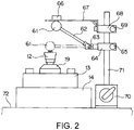
- FIG. 2 is a schematic view of the striking device of the present invention.
- FIG. 3 is an enlarged cross-sectional view showing a state that the fixed side gripper 12 is struck by a steel ball 61.
- the striking device of the present invention includes an arm 62 capable of swinging around a spindle 63, and a steel ball 61 used as a weight which is arranged in an end part of the arm 62 on the opposite side of the spindle 63.
- the spindle 63 is supported by a supporting part 64 which is capable of lifting up and down with respect to a post 71 erected on a magnet stand 70.
- the supporting part 64 that supports the spindle 63 can be fixed in a position at any height of the post 71 by operating a screw 65.
- the magnet stand 70 is placed on a base 72 in this figure, but the magnet stand 70 may also be placed on the table 14.
- a supporting part 68 that supports a supporting plate 67 is arranged in a position of the post 71 and above the supporting part 64.
- the supporting part 68 that supports the supporting plate 67 can be fixed in a position at any height of the post 71 by operating a screw 69.
- a permanent magnet 66 is placed above the supporting plate 67. As shown by a solid line in FIG. 2 , when the steel ball 61 is disposed at a height position which is in contact with the lower surface of the supporting plate 67, the permanent magnet 66 fixes the steel ball 61 by a magnetic force in a standby height position which is in contact with the lower surface of the supporting plate 67. Then, when the permanent magnet 66 is removed from the state shown in FIG.
- the steel ball 61 falls down in an arc shape from the standby height position shown by the solid line in FIG. 2 into a state shown by an imaginary line in FIG. 2 .
- the supporting plate 67 is made of non-magnetic material such as aluminum, stainless steel or plastic.
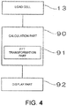
- FIG. 4 is a block diagram showing a control measurement system including a calculation part 90 which is used along with the striking device of the present invention.
- the control measurement system may be configured as a part of the high-speed tensile testing machine shown in FIG. 1 , or may be separately prepared for the measurement of natural frequency.
- the calculation part 90 is connected to the load cell 13 and a display part 92 which is configured by a liquid crystal display panel or the like.
- the calculation part 90 is provided with an FFT transformation part 91 for performing a fast Fourier transform on a signal transmitted from the load cell 13.
- the fast Fourier transform is performed on the signal from the load cell 13 in the FFT transformation part 91, and the natural frequency of the system including the load cell 13 and the fixed-side gripper 12 is calculated in the calculation part 90.
- the calculated natural frequency is displayed in the display part 92.
- the steel ball 61 collides with the two grip teeth 81 at the same time, but it is an ideal situation. Actually, it is considered that the steel ball 61 usually collides with one grip tooth 81. There is no particular problem in the striking function even in this case. Besides, according to the material of the test piece 82, the leading end thereof may project a little above the grip teeth 81, making the steel ball 61 collide with the leading end of the test piece 82.
- the position of the magnet stand 70 is adjusted and the height position of the supporting part 64 that supports the spindle 63 is adjusted, so that the lower surface of the steel ball 61 is in contact with the upper end of the fixed-side gripper 12 in a state that the arm 62 faces to a horizontal direction as shown by the imaginary line in FIG. 2 .
- the supporting part 68 that supports the supporting plate 67 is arranged at a position height position at which the steel ball 61 may be arranged in a position suitable for striking. Then, as shown by the solid line in FIG. 2 , by the action of the permanent magnet 66, the steel ball 61 is fixed in the standby height position that is in contact with the lower surface of the supporting plate 67.
- the permanent magnet 66 is removed from the upper surface of the supporting plate 67.
- the steel ball 61 fixed in the standby height position is released from the fixation in the standby height position, and falls down in an arc shape along with an oscillation of the arm 62 around the spindle 63.
- the steel ball 61 strikes the pair of grip teeth 81 in the fixed side gripper 12 toward a direction (the vertical direction in FIG. 2 ) parallel to the load direction of the test force during the material test that is conducted by the material testing machine shown in FIG. 1 .
- the strike is also performed coaxially with the load shaft.
- the vibration that is generated in the system including the load cell 13 and the fixed-side gripper 12 by the strike is measured by a force detecting function of the load cell 13. Then, the fast Fourier transform is performed, by the FFT transformation part 91 in the calculation part 90, on a detection signal of the vibration force detected by the load cell 13. In this way, the natural frequency of the system including the load cell 13 and the fixed-side gripper 12 is calculated. The calculated natural frequency is displayed in the display part 92.
- the load cell 13 is not only connected to the fixed-side gripper 12, but also in contact with the table 14.
- a detection part such as a strain gauge for detecting the force in the load cell 13 is stored in a strain generating part existing in a region 19 shown in FIG. 2 .
- the load cell 13 is divided into an upper part and a lower part by the strain generating part arranged inside. Because the strain generating part has the nature of spring, the vibration of the system including the fixed-side gripper 12 mainly occurs above the strain generating part. Therefore, the table 14 which is in contact with the load cell 13 does not affect the natural frequency of the system including the load cell 13 and the fixed side gripper 12.
- the striking device of the present invention by adjusting the arrangement of the magnet stand 70 that supports the post 71 and the height position of the supporting part 64 that supports the spindle 63, the same position of the fixed-side gripper 12 can be always struck by the steel ball 61. Besides, by adjusting the height position of the supporting part 68 that supports the supporting plate 67, the fixed side gripper 12 can be always struck with a fixed force by the steel ball 61. Therefore, a simple configuration is provided and the natural frequency of the system including the load cell 13 can be simply and accurately measured.
- an effect of the magnetic force to the steel ball 61 is eliminated and the steel ball 61 falls down in an arc shape by removing the permanent magnet 66 from the upper surface of the supporting plate 67, but a configuration may also be adopted in which an electromagnet is used instead of the permanent magnet 66 and an electromagnetic force of the electromagnet is turned on/off. Besides, a configuration may be adopted in which the steel ball 61 is supported by a mechanical holding mechanism.
- the present invention is applied in the high-speed tensile testing machine including an approach mechanism, but the approach mechanism is not always required according to a test speed.
- the vibration may cause problems even when a test is conducted at a maximum speed in a static tensile testing machine, and thus the present invention can also be applied in this case.
Landscapes
- Physics & Mathematics (AREA)
- General Physics & Mathematics (AREA)
- General Health & Medical Sciences (AREA)
- Chemical & Material Sciences (AREA)
- Analytical Chemistry (AREA)
- Biochemistry (AREA)
- Life Sciences & Earth Sciences (AREA)
- Health & Medical Sciences (AREA)
- Immunology (AREA)
- Pathology (AREA)
- Acoustics & Sound (AREA)
- Investigating Strength Of Materials By Application Of Mechanical Stress (AREA)
- Investigating Or Analyzing Materials By The Use Of Ultrasonic Waves (AREA)
Abstract
Description
- The present invention relates to a striking device that is used to measure a natural frequency of a system including a force detector used in a material testing machine such as a high-speed tensile testing machine, and to a natural frequency measuring device using the striking device.
- The high-speed tensile testing machine has a configuration in which a tensile test force is applied by causing a moving side gripper to move at a high speed in a state that two ends of a test piece are gripped by the moving-side gripper and a fixed-side gripper (see
patent literature 1, Japanese Laid-Open No.2006-10409 - When a material test, such as the above-mentioned high-speed tensile test, a charpy impact test or the like, is conducted in which a test force is applied to the test piece in a short time, the natural frequency (natural vibration) of the force detector such as a load cell affects the test result. That is, when the natural frequency of the force detector is lower than the frequency generated in the test piece during the material test, resonance or vibration occurs easily during the test, and an inertial force thereof is superimposed on a measured value of the force measured by the force detector and causes a large error. Therefore, there are occasions that the natural frequency of the system including force detector such as the force detector and the gripper or the like is measured in advance before such a material test is conducted.
- When the natural frequency is measured, a method is used in which the natural frequency is obtained in the following way, that is, the system including the force detector is struck by a hammer, or an impact is applied to the system including the force detector by dropping a steel ball (a falling ball method) to the system including the force detector, then an output of the force detector at this time is recorded and a FFT (Fast Fourier Transform) analysis or the like is performed on an output value.
- When a natural frequency is measured, a problem is generated that measurement data is not fixed due to the strength of a striking force or the deviation in striking points or the like when a strike is conducted by the hammer. Besides, even when a falling ball method is used, there is a problem that not only does the deviation in collision points cause errors, but measurement operation also becomes complicated because the steel ball rolls after colliding with the system including the force detector.
- The present invention is accomplished to solve the above problems, and is directed to provide a striking device and a natural frequency measuring device capable of simply and accurately measuring a natural frequency of a system including a force detector.
- The invention recited in
technical solution 1 is a striking device, which is used to measure a natural frequency of a system including a force detector used in a material testing machine. The striking device includes an arm capable of swinging around a spindle; a weight arranged in an end part of the arm on a side opposite to the spindle; and a weight fixing mechanism, fixing the weight at standby height position and causing the weight to fall down in an arc shape from the standby height position along with a swing of the arm by releasing the fixation at the standby height position. The system including force detector is struck by the weight toward a direction parallel to a load direction of a test force during a material test that is conducted by the material testing machine. - The invention recited in technical solution 2 is the striking device recited in
technical solution 1, in which the system including force detector includes the force detector and a gripper connected to the force detector, and the weight strikes the gripper. - The invention recited in
technical solution 3 is the striking device recited in technical solution 2, in which the spindle and the weight fixing mechanism are arranged to be capable of lifting up and down relative to a post erected in a vertical direction. - The invention recited in technical solution 4 is the striking device recited in any one of
technical solutions 1 to 3, in which the weight is configured by a magnetic body, and the weight fixing mechanism includes a magnet for fixing the weight at the standby height position by a magnetic force. - The invention recited in technical solution 5 is a natural frequency measuring device which includes the striking device recited in any one of
technical solutions 1 to 4; and an calculation part, calculating the natural frequency of the system including the force detector based on an output signal of the force detector when the system including force detector is struck by the weight. - According to the invention recited in
technical solutions 1 to 5, the weight is made to fall down in an arc shape along with the swing of the arm to strike the system including the force detector toward a direction parallel to a load direction of a test force during a material test. Thus, a simple configuration is provided and the natural frequency of the system including the force detector can be simply and accurately measured. - According to the invention recited in
technical solution 3, the striking position of the weight can be changed corresponding to sizes of the force detector and the gripper. - According to the invention recited in technical solution 4, the fixation of the weight and the release of the fixation can be easily conducted.
-
-
FIG. 1 is a schematic view showing a main part of a high-speed tensile testing machine using a striking device of the present invention. -
FIG. 2 is a schematic view of a striking device of the present invention. -
FIG.3 is an enlarged cross-sectional view showing a state that afixed side gripper 12 is struck by asteel ball 61. -
FIG.4 is a block diagram showing a control measurement system including acalculation part 90 which is used along with the striking device of the present invention. - An embodiment of the present invention is described below based on the drawings.
FIG. 1 is a schematic view showing a main part of a high-speed tensile testing machine using a striking device of the present invention. - In the high-speed tensile testing machine, a
test piece 100 is provided to a high-speed tensile test in a state that the upper and lower ends of thetest piece 100 are gripped by a moving-side gripper 11 and a fixed-side gripper 12. The moving-side gripper 11 is supported at a lower end part of a movingmember 51 via acoupling member 45. On the other hand, the fixed-side gripper 12 is fixed to a table 14 via aload cell 13 which is used as a force detector of the present invention. - The moving-
member 51 which is connected to the moving-side gripper 11 via thecoupling member 45 is disposed in a cavity formed within apiston 53 disposed above. Ataper part 52 extending upward is formed in an upper end part of the movingmember 51. On the other hand, ataper part 54 extending upward at a substantially same angle as thetaper part 52 is formed in the lower end part of the cavity in thepiston 53. Furthermore, thepiston 53 is lifted up and down in a vertical direction by the drive of a hydraulic cylinder that is not illustrated. Therefore, when thepiston 53 is lifted up at a high speed, after an approach zone before thetaper part 52 in the movingmember 51 and thetaper part 54 in thepiston 53 come into contact, the movingmember 51 moves upward at a high initial speed along with thepiston 53. In this way, a high-speed tensile load is applied to thetest piece 100. - A displacement gauge for measuring an extension of the
test piece 100 during the high-speed tensile test includes a movingbody 23 and a fixedbody 21. The movingbody 23 is configured by a pipe made of a conductor, and the fixedbody 21 is configured by a coil. Then, the displacement gauge has a configuration in which the change of an inductance of the fixedbody 21 that is a coil caused by the movement of the movingbody 23 is detected to calculate the extension of thetest piece 100. A general strain gauge can also be used as the displacement gauge. - Here, the moving
body 23 in the displacement gauge is coupled to the moving-side gripper 11 in a state of being supported by a supportingmember 41. Besides, the fixedbody 21 in the displacement gauge is supported by a supportingarm 16. The supportingarm 16 is configured to be capable of lifting up and down relative to apost 15 erected on the table 14, and to be fixed after adjusting a height position by actions of apositioning ring 17 and a fixinggripper 18. - When the
piston 53 is lifted up at a high speed during the high-speed tensile test having the above configuration, the movingmember 51 is lifted up at a high speed after passing through the approach zone of thepiston 53. In this way, the high-speed tensile load is applied to thetest piece 100 via the moving-side gripper 11. Then, the moving-side gripper 11 moves upward due to the extension of thetest piece 100. Due to the movement of the moving-side gripper 11, an insertion amount of the coil used as the fixedbody 21 into the pipe forming the movingbody 23 in the displacement gauge is reduced, and the inductance changes. Then, the inductance is detected, and an amount of displacement of the displacement gauge, that is, the extension of thetest piece 100 is calculated based on the change. - Next, the configuration of the striking device of the present invention is described.
FIG. 2 is a schematic view of the striking device of the present invention. Besides,FIG. 3 is an enlarged cross-sectional view showing a state that the fixedside gripper 12 is struck by asteel ball 61. - The striking device of the present invention includes an
arm 62 capable of swinging around aspindle 63, and asteel ball 61 used as a weight which is arranged in an end part of thearm 62 on the opposite side of thespindle 63. Thespindle 63 is supported by a supportingpart 64 which is capable of lifting up and down with respect to apost 71 erected on amagnet stand 70. The supportingpart 64 that supports thespindle 63 can be fixed in a position at any height of thepost 71 by operating ascrew 65. In addition, the magnet stand 70 is placed on a base 72 in this figure, but the magnet stand 70 may also be placed on the table 14. - A supporting
part 68 that supports a supportingplate 67 is arranged in a position of thepost 71 and above the supportingpart 64. The supportingpart 68 that supports the supportingplate 67 can be fixed in a position at any height of thepost 71 by operating a screw 69. In addition, apermanent magnet 66 is placed above the supportingplate 67. As shown by a solid line inFIG. 2 , when thesteel ball 61 is disposed at a height position which is in contact with the lower surface of the supportingplate 67, thepermanent magnet 66 fixes thesteel ball 61 by a magnetic force in a standby height position which is in contact with the lower surface of the supportingplate 67. Then, when thepermanent magnet 66 is removed from the state shown inFIG. 2 , thesteel ball 61 falls down in an arc shape from the standby height position shown by the solid line inFIG. 2 into a state shown by an imaginary line inFIG. 2 . In addition, the supportingplate 67 is made of non-magnetic material such as aluminum, stainless steel or plastic. -
FIG. 4 is a block diagram showing a control measurement system including acalculation part 90 which is used along with the striking device of the present invention. The control measurement system may be configured as a part of the high-speed tensile testing machine shown inFIG. 1 , or may be separately prepared for the measurement of natural frequency. - The
calculation part 90 is connected to theload cell 13 and adisplay part 92 which is configured by a liquid crystal display panel or the like. Thecalculation part 90 is provided with anFFT transformation part 91 for performing a fast Fourier transform on a signal transmitted from theload cell 13. The fast Fourier transform is performed on the signal from theload cell 13 in theFFT transformation part 91, and the natural frequency of the system including theload cell 13 and the fixed-side gripper 12 is calculated in thecalculation part 90. The calculated natural frequency is displayed in thedisplay part 92. - When the natural frequency of the system including the
load cell 13 serving as a force detector and the fixed-side gripper 12 is measured by the striking device having such a configuration, as shown inFIG. 3 , adummy test piece 82 is disposed on a supportingplate 83, and thedummy test piece 82 is gripped by a pair ofgrip teeth 81 in the fixed-side gripper 12. The reason for this is to cause thegripper 12 to vibrate integrally including thegrip teeth 81 or thetest piece 82, and to prevent a positional deviation from generating on the pair ofgrip teeth 81 when the pair ofgrip teeth 81 in the fixed-side gripper 12 described below collides with thesteel ball 61. In addition, inFIG. 3 , thesteel ball 61 collides with the twogrip teeth 81 at the same time, but it is an ideal situation. Actually, it is considered that thesteel ball 61 usually collides with onegrip tooth 81. There is no particular problem in the striking function even in this case. Besides, according to the material of thetest piece 82, the leading end thereof may project a little above thegrip teeth 81, making thesteel ball 61 collide with the leading end of thetest piece 82. - In this state, the position of the magnet stand 70 is adjusted and the height position of the supporting
part 64 that supports thespindle 63 is adjusted, so that the lower surface of thesteel ball 61 is in contact with the upper end of the fixed-side gripper 12 in a state that thearm 62 faces to a horizontal direction as shown by the imaginary line inFIG. 2 . Besides, the supportingpart 68 that supports the supportingplate 67 is arranged at a position height position at which thesteel ball 61 may be arranged in a position suitable for striking. Then, as shown by the solid line inFIG. 2 , by the action of thepermanent magnet 66, thesteel ball 61 is fixed in the standby height position that is in contact with the lower surface of the supportingplate 67. - In this state, the
permanent magnet 66 is removed from the upper surface of the supportingplate 67. In this way, thesteel ball 61 fixed in the standby height position is released from the fixation in the standby height position, and falls down in an arc shape along with an oscillation of thearm 62 around thespindle 63. Then, thesteel ball 61 strikes the pair ofgrip teeth 81 in the fixedside gripper 12 toward a direction (the vertical direction inFIG. 2 ) parallel to the load direction of the test force during the material test that is conducted by the material testing machine shown inFIG. 1 . Besides, the strike is also performed coaxially with the load shaft. - The vibration that is generated in the system including the
load cell 13 and the fixed-side gripper 12 by the strike is measured by a force detecting function of theload cell 13. Then, the fast Fourier transform is performed, by theFFT transformation part 91 in thecalculation part 90, on a detection signal of the vibration force detected by theload cell 13. In this way, the natural frequency of the system including theload cell 13 and the fixed-side gripper 12 is calculated. The calculated natural frequency is displayed in thedisplay part 92. - In addition, the
load cell 13 is not only connected to the fixed-side gripper 12, but also in contact with the table 14. However, a detection part such as a strain gauge for detecting the force in theload cell 13 is stored in a strain generating part existing in aregion 19 shown inFIG. 2 . Theload cell 13 is divided into an upper part and a lower part by the strain generating part arranged inside. Because the strain generating part has the nature of spring, the vibration of the system including the fixed-side gripper 12 mainly occurs above the strain generating part. Therefore, the table 14 which is in contact with theload cell 13 does not affect the natural frequency of the system including theload cell 13 and the fixedside gripper 12. - As described above, according to the striking device of the present invention, by adjusting the arrangement of the magnet stand 70 that supports the
post 71 and the height position of the supportingpart 64 that supports thespindle 63, the same position of the fixed-side gripper 12 can be always struck by thesteel ball 61. Besides, by adjusting the height position of the supportingpart 68 that supports the supportingplate 67, the fixedside gripper 12 can be always struck with a fixed force by thesteel ball 61. Therefore, a simple configuration is provided and the natural frequency of the system including theload cell 13 can be simply and accurately measured. - In addition, in the above-described embodiment, an effect of the magnetic force to the
steel ball 61 is eliminated and thesteel ball 61 falls down in an arc shape by removing thepermanent magnet 66 from the upper surface of the supportingplate 67, but a configuration may also be adopted in which an electromagnet is used instead of thepermanent magnet 66 and an electromagnetic force of the electromagnet is turned on/off. Besides, a configuration may be adopted in which thesteel ball 61 is supported by a mechanical holding mechanism. - Besides, in the above-described embodiment, the present invention is applied in the high-speed tensile testing machine including an approach mechanism, but the approach mechanism is not always required according to a test speed. For example, the vibration may cause problems even when a test is conducted at a maximum speed in a static tensile testing machine, and thus the present invention can also be applied in this case.
-
- 11
- moving-side gripper
- 12
- fixed-side gripper
- 13
- load cell
- 14
- table
- 51
- moving member
- 52
- taper part
- 53
- piston
- 54
- taper part
- 61
- steel ball
- 62
- arm
- 63
- spindle
- 64
- supporting part
- 66
- permanent magnet
- 67
- supporting plate
- 68
- supporting part
- 70
- magnet stand
- 71
- post
- 90
- calculation part
- 91
- FFT transformation part
- 92
- display part
- 100
- test piece
Claims (5)
- A striking device, measuring a natural frequency of a system comprising a force detector (13) used in a material testing machine, characterized in that the striking device comprises
an arm (62), capable of swinging around a spindle (63);
a weight (61), arranged in an end part of the arm (62) on a side opposite to the spindle (63); and
a weight fixing mechanism (64), fixing the weight at a standby height position and causing the weight (61) to fall down in an arc shape from the standby height position along with a swing of the arm (62) by releasing the fixation at the standby height position,
wherein the system comprising the force detector is struck by the weight (61) toward a direction parallel to a load direction of a test force during a material test that is conducted by the material testing machine. - The striking device according to claim 1, wherein
the system comprising the force detector comprises the force detector (13) and a gripper (12) connected to the force detector (13), and
the weight (61) strikes the gripper (12). - The striking device according to claim 2, wherein
the spindle (63) and the weight fixing mechanism (64) are arranged to be capable of lifting up and down relative to a post (71) erected in a vertical direction. - The striking device according to any one of claims 1 to 3, wherein
the weight (61) is configured by a magnetic body, and
the weight fixing mechanism (64) includes a magnet (66) for fixing the weight (61) at the standby height position by a magnetic force. - A natural frequency measuring device, comprising:the striking device, according to any one of claims 1 to 4; anda calculation part (90), calculating the natural frequency of the system comprising the force detector based on an output signal of the force detector (13) when the system comprising the force detector is struck by the weight (61).
Applications Claiming Priority (1)
| Application Number | Priority Date | Filing Date | Title |
|---|---|---|---|
| JP2018011638A JP7026901B2 (en) | 2018-01-26 | 2018-01-26 | Strike device and natural frequency measuring device |
Publications (3)
| Publication Number | Publication Date |
|---|---|
| EP3517928A2 true EP3517928A2 (en) | 2019-07-31 |
| EP3517928A3 EP3517928A3 (en) | 2019-08-07 |
| EP3517928B1 EP3517928B1 (en) | 2023-11-29 |
Family
ID=64899194
Family Applications (1)
| Application Number | Title | Priority Date | Filing Date |
|---|---|---|---|
| EP18212070.9A Active EP3517928B1 (en) | 2018-01-26 | 2018-12-12 | Natural frequency measuring device and method of measuring a natural frequency of a system |
Country Status (4)
| Country | Link |
|---|---|
| US (1) | US10969312B2 (en) |
| EP (1) | EP3517928B1 (en) |
| JP (1) | JP7026901B2 (en) |
| CN (1) | CN110082199A (en) |
Cited By (3)
| Publication number | Priority date | Publication date | Assignee | Title |
|---|---|---|---|---|
| CN112254807A (en) * | 2020-10-26 | 2021-01-22 | 北京中科泛华测控技术有限公司 | Engine blade natural frequency testing system |
| CN119198387A (en) * | 2024-11-14 | 2024-12-27 | 江苏助您智能机械科技有限公司 | A kind of automobile high pressure casting mold performance detection device and detection method |
| CN119935471A (en) * | 2025-04-03 | 2025-05-06 | 全南县优冠体育用品有限公司 | A soccer ball rebound rate measuring device |
Families Citing this family (5)
| Publication number | Priority date | Publication date | Assignee | Title |
|---|---|---|---|---|
| JP7306464B2 (en) * | 2019-09-13 | 2023-07-11 | 株式会社島津製作所 | TENSILE TESTER AND CONTROL METHOD FOR TENSILE TESTER |
| CN111366482B (en) * | 2020-03-27 | 2023-04-11 | 山西采薇集能科技有限公司 | Dynamic high-speed loading ejection device |
| CN113029491B (en) * | 2021-03-13 | 2023-09-01 | 质与实验室(深圳)有限公司 | A high-end manufacturing product quality inspection random hitting equipment |
| CN116952732B (en) * | 2023-07-11 | 2024-08-13 | 徐州市威固特种玻璃有限公司 | Glass production is with many testing arrangement |
| CN118329666B (en) * | 2024-06-13 | 2024-08-06 | 大庆湃瑞环保科技有限公司 | Building construction check out test set |
Citations (1)
| Publication number | Priority date | Publication date | Assignee | Title |
|---|---|---|---|---|
| JP2006010409A (en) | 2004-06-23 | 2006-01-12 | Shimadzu Corp | Extensometer |
Family Cites Families (23)
| Publication number | Priority date | Publication date | Assignee | Title |
|---|---|---|---|---|
| DE333410C (en) * | 1920-02-07 | 1921-02-23 | Louis Schopper Fa | Device for tensile strength testing by means of a hammer |
| US2418916A (en) * | 1943-07-01 | 1947-04-15 | Steel City Testing Machines In | Machine for testing hardness of metals and other materials |
| US4144740A (en) * | 1978-05-01 | 1979-03-20 | The B. F. Goodrich Company | Testing apparatus and method for measuring cutting, chipping and abrasion resistance |
| US6494076B1 (en) * | 1998-12-22 | 2002-12-17 | The Goodyear Tire & Rubber Company | Pendulum rolling resistant test |
| US6871525B2 (en) * | 2002-06-14 | 2005-03-29 | Riddell, Inc. | Method and apparatus for testing football helmets |
| JP4043866B2 (en) * | 2002-07-05 | 2008-02-06 | 横浜ゴム株式会社 | Method for measuring rigidity distribution of golf club head and golf club |
| JP3891287B2 (en) * | 2003-01-14 | 2007-03-14 | 株式会社島津製作所 | Load cell for load measurement and material testing machine |
| JP4033119B2 (en) * | 2003-12-10 | 2008-01-16 | 株式会社島津製作所 | Material testing method, material testing machine |
| CN100587463C (en) * | 2004-07-08 | 2010-02-03 | 日东电工株式会社 | Impact test device and impact test method |
| JP4619157B2 (en) * | 2004-07-08 | 2011-01-26 | 日東電工株式会社 | Impact test apparatus and impact test method |
| US20060094571A1 (en) * | 2004-09-07 | 2006-05-04 | Polidi Richard Z | Mechanical weightlifting machine |
| DE202006003466U1 (en) * | 2006-03-06 | 2006-05-04 | Schmidt, Werner | Test apparatus, for testing flexible or elastic walls of sports halls or similar constructions, uses drop weight hanging from frame-like pendulum |
| JP2008164463A (en) * | 2006-12-28 | 2008-07-17 | Shimadzu Corp | testing machine |
| US20080236347A1 (en) * | 2007-03-26 | 2008-10-02 | Kenneth Jack Spencer | Swinging circular saw with lateral movement |
| KR101202113B1 (en) * | 2007-11-27 | 2012-11-15 | 무겐 인코포레이티드 | Hit position detecting device, hit position detecting method, and method for manufacturing hit position detecting device |
| KR101295171B1 (en) * | 2011-12-21 | 2013-08-09 | 한국항공우주연구원 | Impact Tester |
| KR101301761B1 (en) * | 2013-02-18 | 2013-08-29 | 한국기계연구원 | Impact machine device using restoring force |
| ES2473666B1 (en) * | 2013-12-23 | 2015-04-13 | Fundación Centro Tecnologias Aeronauticas | PENDULUM DEVICE FOR LOW ENERGY IMPACT TEST |
| CN104941164A (en) * | 2014-03-28 | 2015-09-30 | 上海体育学院 | Pendulum bob capable of adjusting and testing impact strength |
| CN104155076B (en) * | 2014-07-07 | 2016-07-27 | 中国矿业大学 | A kind of working platform type ultromotivity hammer device and method |
| EP3045890A1 (en) * | 2015-01-16 | 2016-07-20 | Veterinärmedizinische Universität Wien | Device for determining the elastic properties of surfaces and floors and method for operating the device |
| ES1156261Y (en) * | 2016-04-12 | 2016-08-08 | Univ Zaragoza | DEVICE FOR THE NON-DESTRUCTIVE MEASURE OF PHYSICAL PROPERTIES ASSOCIATED WITH THE STATE OF CONSERVATION OF OBJECTS |
| CN106073928A (en) * | 2016-06-02 | 2016-11-09 | 复旦大学附属华山医院 | Free fall type animal contusion injuries beating device and striking method |
-
2018
- 2018-01-26 JP JP2018011638A patent/JP7026901B2/en active Active
- 2018-11-16 CN CN201811366115.7A patent/CN110082199A/en active Pending
- 2018-12-12 EP EP18212070.9A patent/EP3517928B1/en active Active
-
2019
- 2019-01-16 US US16/248,809 patent/US10969312B2/en active Active
Patent Citations (1)
| Publication number | Priority date | Publication date | Assignee | Title |
|---|---|---|---|---|
| JP2006010409A (en) | 2004-06-23 | 2006-01-12 | Shimadzu Corp | Extensometer |
Cited By (3)
| Publication number | Priority date | Publication date | Assignee | Title |
|---|---|---|---|---|
| CN112254807A (en) * | 2020-10-26 | 2021-01-22 | 北京中科泛华测控技术有限公司 | Engine blade natural frequency testing system |
| CN119198387A (en) * | 2024-11-14 | 2024-12-27 | 江苏助您智能机械科技有限公司 | A kind of automobile high pressure casting mold performance detection device and detection method |
| CN119935471A (en) * | 2025-04-03 | 2025-05-06 | 全南县优冠体育用品有限公司 | A soccer ball rebound rate measuring device |
Also Published As
| Publication number | Publication date |
|---|---|
| EP3517928B1 (en) | 2023-11-29 |
| US10969312B2 (en) | 2021-04-06 |
| CN110082199A (en) | 2019-08-02 |
| JP2019128314A (en) | 2019-08-01 |
| JP7026901B2 (en) | 2022-03-01 |
| EP3517928A3 (en) | 2019-08-07 |
| US20190234846A1 (en) | 2019-08-01 |
Similar Documents
| Publication | Publication Date | Title |
|---|---|---|
| US10969312B2 (en) | Striking device and natural frequency measuring device | |
| CN102252803B (en) | Dynamic force calibrating device by laser absolute method | |
| KR100903560B1 (en) | Impact tester | |
| CN109633497A (en) | A kind of electromagnet testing stand and detection platform | |
| JP6011486B2 (en) | Material testing machine | |
| CN106706207A (en) | Step force generating device for dynamic calibration of force sensor | |
| KR200452509Y1 (en) | Glass impact tester | |
| CN103115714B (en) | Full-automatic magnetic gauge stand magnetic detecting device | |
| WO2021046904A1 (en) | Weighing device and weighing system | |
| CN103323354A (en) | High-precision dynamic-loading fatigue test apparatus | |
| JP7321433B2 (en) | Test method and device for tightening conditions of screws | |
| JP6134929B2 (en) | Material property evaluation system | |
| CN203337100U (en) | Three dimensional displacement detection device of crystallizer vibration table | |
| JPH1194722A (en) | Method and apparatus for impact tensile test of sheet material | |
| US12590874B2 (en) | Tensile testing machine and method for controlling tensile testing machine | |
| US12332148B2 (en) | Device for measuring and protecting horizontal slide table displacement | |
| CN210464352U (en) | Doorframe supporting deformation detecting instrument | |
| US3285060A (en) | Pendulum impact tester | |
| KR20080018973A (en) | Electronic blow device for concrete nondestructive test | |
| JP4571333B2 (en) | Method of measuring the overturning moment in a vibration generator | |
| Jia et al. | Impact experiment analysis of MEMS ultra-high G piezoresistive shock accelerometer | |
| CN101718602B (en) | Detecting device of working magnetic force of magnetic stand | |
| CN114354428A (en) | A dynamic force sensor calibration method of instrumented impact testing machine based on double pulse method | |
| JP2013092390A (en) | Method and apparatus for measuring impact load | |
| CN223377102U (en) | Ball drop impact testing machine |
Legal Events
| Date | Code | Title | Description |
|---|---|---|---|
| PUAI | Public reference made under article 153(3) epc to a published international application that has entered the european phase |
Free format text: ORIGINAL CODE: 0009012 |
|
| STAA | Information on the status of an ep patent application or granted ep patent |
Free format text: STATUS: REQUEST FOR EXAMINATION WAS MADE |
|
| PUAL | Search report despatched |
Free format text: ORIGINAL CODE: 0009013 |
|
| 17P | Request for examination filed |
Effective date: 20181212 |
|
| AK | Designated contracting states |
Kind code of ref document: A2 Designated state(s): AL AT BE BG CH CY CZ DE DK EE ES FI FR GB GR HR HU IE IS IT LI LT LU LV MC MK MT NL NO PL PT RO RS SE SI SK SM TR |
|
| AX | Request for extension of the european patent |
Extension state: BA ME |
|
| AK | Designated contracting states |
Kind code of ref document: A3 Designated state(s): AL AT BE BG CH CY CZ DE DK EE ES FI FR GB GR HR HU IE IS IT LI LT LU LV MC MK MT NL NO PL PT RO RS SE SI SK SM TR |
|
| AX | Request for extension of the european patent |
Extension state: BA ME |
|
| RIC1 | Information provided on ipc code assigned before grant |
Ipc: G01N 3/10 20060101ALI20190628BHEP Ipc: G01N 3/303 20060101ALI20190628BHEP Ipc: G01N 3/307 20060101ALI20190628BHEP Ipc: G01M 7/08 20060101ALI20190628BHEP Ipc: G01N 3/14 20060101AFI20190628BHEP |
|
| RAP1 | Party data changed (applicant data changed or rights of an application transferred) |
Owner name: SHIMADZU CORPORATION |
|
| RIN1 | Information on inventor provided before grant (corrected) |
Inventor name: TAKII, TADAOKI Inventor name: NISHIMURA, MASAKI Inventor name: KASAI, NORIFUMI Inventor name: TANIGUCHI, SATOSHI Inventor name: KIMURA, MITUSHIKO |
|
| RAP1 | Party data changed (applicant data changed or rights of an application transferred) |
Owner name: CITY OF NAGOYA Owner name: SHIMADZU CORPORATION Owner name: AKITA PREFECTURE Owner name: OSAKA RESEARCH INSTITUTE OF INDUSTRIAL SCIENCE AND TECHNOLOGY |
|
| STAA | Information on the status of an ep patent application or granted ep patent |
Free format text: STATUS: EXAMINATION IS IN PROGRESS |
|
| 17Q | First examination report despatched |
Effective date: 20210609 |
|
| GRAP | Despatch of communication of intention to grant a patent |
Free format text: ORIGINAL CODE: EPIDOSNIGR1 |
|
| STAA | Information on the status of an ep patent application or granted ep patent |
Free format text: STATUS: GRANT OF PATENT IS INTENDED |
|
| INTG | Intention to grant announced |
Effective date: 20230721 |
|
| RIN1 | Information on inventor provided before grant (corrected) |
Inventor name: KASAI, NORIFUMI Inventor name: KIMURA, MITUSHIKO Inventor name: TANIGUCHI, SATOSHI Inventor name: NISHIMURA, MASAKI Inventor name: TAKII, TADAOKI |
|
| GRAS | Grant fee paid |
Free format text: ORIGINAL CODE: EPIDOSNIGR3 |
|
| GRAA | (expected) grant |
Free format text: ORIGINAL CODE: 0009210 |
|
| STAA | Information on the status of an ep patent application or granted ep patent |
Free format text: STATUS: THE PATENT HAS BEEN GRANTED |
|
| AK | Designated contracting states |
Kind code of ref document: B1 Designated state(s): AL AT BE BG CH CY CZ DE DK EE ES FI FR GB GR HR HU IE IS IT LI LT LU LV MC MK MT NL NO PL PT RO RS SE SI SK SM TR |
|
| REG | Reference to a national code |
Ref country code: GB Ref legal event code: FG4D |
|
| RIN1 | Information on inventor provided before grant (corrected) |
Inventor name: KASAI, NORIFUMI Inventor name: KIMURA, MITSUHIKO Inventor name: TANIGUCHI, SATOSHI Inventor name: NISHIMURA, MASAKI Inventor name: TAKII, TADAOKI |
|
| REG | Reference to a national code |
Ref country code: CH Ref legal event code: EP |
|
| REG | Reference to a national code |
Ref country code: DE Ref legal event code: R096 Ref document number: 602018061755 Country of ref document: DE |
|
| REG | Reference to a national code |
Ref country code: IE Ref legal event code: FG4D |
|
| REG | Reference to a national code |
Ref country code: LT Ref legal event code: MG9D |
|
| REG | Reference to a national code |
Ref country code: NL Ref legal event code: MP Effective date: 20231129 |
|
| PG25 | Lapsed in a contracting state [announced via postgrant information from national office to epo] |
Ref country code: GR Free format text: LAPSE BECAUSE OF FAILURE TO SUBMIT A TRANSLATION OF THE DESCRIPTION OR TO PAY THE FEE WITHIN THE PRESCRIBED TIME-LIMIT Effective date: 20240301 |
|
| PG25 | Lapsed in a contracting state [announced via postgrant information from national office to epo] |
Ref country code: IS Free format text: LAPSE BECAUSE OF FAILURE TO SUBMIT A TRANSLATION OF THE DESCRIPTION OR TO PAY THE FEE WITHIN THE PRESCRIBED TIME-LIMIT Effective date: 20240329 |
|
| PG25 | Lapsed in a contracting state [announced via postgrant information from national office to epo] |
Ref country code: LT Free format text: LAPSE BECAUSE OF FAILURE TO SUBMIT A TRANSLATION OF THE DESCRIPTION OR TO PAY THE FEE WITHIN THE PRESCRIBED TIME-LIMIT Effective date: 20231129 |
|
| PG25 | Lapsed in a contracting state [announced via postgrant information from national office to epo] |
Ref country code: ES Free format text: LAPSE BECAUSE OF FAILURE TO SUBMIT A TRANSLATION OF THE DESCRIPTION OR TO PAY THE FEE WITHIN THE PRESCRIBED TIME-LIMIT Effective date: 20231129 |
|
| PG25 | Lapsed in a contracting state [announced via postgrant information from national office to epo] |
Ref country code: LT Free format text: LAPSE BECAUSE OF FAILURE TO SUBMIT A TRANSLATION OF THE DESCRIPTION OR TO PAY THE FEE WITHIN THE PRESCRIBED TIME-LIMIT Effective date: 20231129 Ref country code: IS Free format text: LAPSE BECAUSE OF FAILURE TO SUBMIT A TRANSLATION OF THE DESCRIPTION OR TO PAY THE FEE WITHIN THE PRESCRIBED TIME-LIMIT Effective date: 20240329 Ref country code: GR Free format text: LAPSE BECAUSE OF FAILURE TO SUBMIT A TRANSLATION OF THE DESCRIPTION OR TO PAY THE FEE WITHIN THE PRESCRIBED TIME-LIMIT Effective date: 20240301 Ref country code: ES Free format text: LAPSE BECAUSE OF FAILURE TO SUBMIT A TRANSLATION OF THE DESCRIPTION OR TO PAY THE FEE WITHIN THE PRESCRIBED TIME-LIMIT Effective date: 20231129 Ref country code: BG Free format text: LAPSE BECAUSE OF FAILURE TO SUBMIT A TRANSLATION OF THE DESCRIPTION OR TO PAY THE FEE WITHIN THE PRESCRIBED TIME-LIMIT Effective date: 20240229 |
|
| REG | Reference to a national code |
Ref country code: AT Ref legal event code: MK05 Ref document number: 1636595 Country of ref document: AT Kind code of ref document: T Effective date: 20231129 |
|
| PG25 | Lapsed in a contracting state [announced via postgrant information from national office to epo] |
Ref country code: NL Free format text: LAPSE BECAUSE OF FAILURE TO SUBMIT A TRANSLATION OF THE DESCRIPTION OR TO PAY THE FEE WITHIN THE PRESCRIBED TIME-LIMIT Effective date: 20231129 |
|
| PG25 | Lapsed in a contracting state [announced via postgrant information from national office to epo] |
Ref country code: SE Free format text: LAPSE BECAUSE OF FAILURE TO SUBMIT A TRANSLATION OF THE DESCRIPTION OR TO PAY THE FEE WITHIN THE PRESCRIBED TIME-LIMIT Effective date: 20231129 Ref country code: RS Free format text: LAPSE BECAUSE OF FAILURE TO SUBMIT A TRANSLATION OF THE DESCRIPTION OR TO PAY THE FEE WITHIN THE PRESCRIBED TIME-LIMIT Effective date: 20231129 Ref country code: PL Free format text: LAPSE BECAUSE OF FAILURE TO SUBMIT A TRANSLATION OF THE DESCRIPTION OR TO PAY THE FEE WITHIN THE PRESCRIBED TIME-LIMIT Effective date: 20231129 Ref country code: NO Free format text: LAPSE BECAUSE OF FAILURE TO SUBMIT A TRANSLATION OF THE DESCRIPTION OR TO PAY THE FEE WITHIN THE PRESCRIBED TIME-LIMIT Effective date: 20240229 Ref country code: NL Free format text: LAPSE BECAUSE OF FAILURE TO SUBMIT A TRANSLATION OF THE DESCRIPTION OR TO PAY THE FEE WITHIN THE PRESCRIBED TIME-LIMIT Effective date: 20231129 Ref country code: LV Free format text: LAPSE BECAUSE OF FAILURE TO SUBMIT A TRANSLATION OF THE DESCRIPTION OR TO PAY THE FEE WITHIN THE PRESCRIBED TIME-LIMIT Effective date: 20231129 Ref country code: HR Free format text: LAPSE BECAUSE OF FAILURE TO SUBMIT A TRANSLATION OF THE DESCRIPTION OR TO PAY THE FEE WITHIN THE PRESCRIBED TIME-LIMIT Effective date: 20231129 |
|
| PG25 | Lapsed in a contracting state [announced via postgrant information from national office to epo] |
Ref country code: DK Free format text: LAPSE BECAUSE OF FAILURE TO SUBMIT A TRANSLATION OF THE DESCRIPTION OR TO PAY THE FEE WITHIN THE PRESCRIBED TIME-LIMIT Effective date: 20231129 |
|
| PG25 | Lapsed in a contracting state [announced via postgrant information from national office to epo] |
Ref country code: CZ Free format text: LAPSE BECAUSE OF FAILURE TO SUBMIT A TRANSLATION OF THE DESCRIPTION OR TO PAY THE FEE WITHIN THE PRESCRIBED TIME-LIMIT Effective date: 20231129 Ref country code: AT Free format text: LAPSE BECAUSE OF FAILURE TO SUBMIT A TRANSLATION OF THE DESCRIPTION OR TO PAY THE FEE WITHIN THE PRESCRIBED TIME-LIMIT Effective date: 20231129 |
|
| PG25 | Lapsed in a contracting state [announced via postgrant information from national office to epo] |
Ref country code: SK Free format text: LAPSE BECAUSE OF FAILURE TO SUBMIT A TRANSLATION OF THE DESCRIPTION OR TO PAY THE FEE WITHIN THE PRESCRIBED TIME-LIMIT Effective date: 20231129 |
|
| PG25 | Lapsed in a contracting state [announced via postgrant information from national office to epo] |
Ref country code: SM Free format text: LAPSE BECAUSE OF FAILURE TO SUBMIT A TRANSLATION OF THE DESCRIPTION OR TO PAY THE FEE WITHIN THE PRESCRIBED TIME-LIMIT Effective date: 20231129 Ref country code: SK Free format text: LAPSE BECAUSE OF FAILURE TO SUBMIT A TRANSLATION OF THE DESCRIPTION OR TO PAY THE FEE WITHIN THE PRESCRIBED TIME-LIMIT Effective date: 20231129 Ref country code: RO Free format text: LAPSE BECAUSE OF FAILURE TO SUBMIT A TRANSLATION OF THE DESCRIPTION OR TO PAY THE FEE WITHIN THE PRESCRIBED TIME-LIMIT Effective date: 20231129 Ref country code: IT Free format text: LAPSE BECAUSE OF FAILURE TO SUBMIT A TRANSLATION OF THE DESCRIPTION OR TO PAY THE FEE WITHIN THE PRESCRIBED TIME-LIMIT Effective date: 20231129 Ref country code: EE Free format text: LAPSE BECAUSE OF FAILURE TO SUBMIT A TRANSLATION OF THE DESCRIPTION OR TO PAY THE FEE WITHIN THE PRESCRIBED TIME-LIMIT Effective date: 20231129 Ref country code: DK Free format text: LAPSE BECAUSE OF FAILURE TO SUBMIT A TRANSLATION OF THE DESCRIPTION OR TO PAY THE FEE WITHIN THE PRESCRIBED TIME-LIMIT Effective date: 20231129 Ref country code: CZ Free format text: LAPSE BECAUSE OF FAILURE TO SUBMIT A TRANSLATION OF THE DESCRIPTION OR TO PAY THE FEE WITHIN THE PRESCRIBED TIME-LIMIT Effective date: 20231129 Ref country code: AT Free format text: LAPSE BECAUSE OF FAILURE TO SUBMIT A TRANSLATION OF THE DESCRIPTION OR TO PAY THE FEE WITHIN THE PRESCRIBED TIME-LIMIT Effective date: 20231129 |
|
| REG | Reference to a national code |
Ref country code: CH Ref legal event code: PL |
|
| PG25 | Lapsed in a contracting state [announced via postgrant information from national office to epo] |
Ref country code: PT Free format text: LAPSE BECAUSE OF FAILURE TO SUBMIT A TRANSLATION OF THE DESCRIPTION OR TO PAY THE FEE WITHIN THE PRESCRIBED TIME-LIMIT Effective date: 20240401 |
|
| PG25 | Lapsed in a contracting state [announced via postgrant information from national office to epo] |
Ref country code: LU Free format text: LAPSE BECAUSE OF NON-PAYMENT OF DUE FEES Effective date: 20231212 |
|
| PG25 | Lapsed in a contracting state [announced via postgrant information from national office to epo] |
Ref country code: MC Free format text: LAPSE BECAUSE OF FAILURE TO SUBMIT A TRANSLATION OF THE DESCRIPTION OR TO PAY THE FEE WITHIN THE PRESCRIBED TIME-LIMIT Effective date: 20231129 |
|
| REG | Reference to a national code |
Ref country code: BE Ref legal event code: MM Effective date: 20231231 |
|
| PG25 | Lapsed in a contracting state [announced via postgrant information from national office to epo] |
Ref country code: PT Free format text: LAPSE BECAUSE OF FAILURE TO SUBMIT A TRANSLATION OF THE DESCRIPTION OR TO PAY THE FEE WITHIN THE PRESCRIBED TIME-LIMIT Effective date: 20240401 Ref country code: MC Free format text: LAPSE BECAUSE OF FAILURE TO SUBMIT A TRANSLATION OF THE DESCRIPTION OR TO PAY THE FEE WITHIN THE PRESCRIBED TIME-LIMIT Effective date: 20231129 Ref country code: LU Free format text: LAPSE BECAUSE OF NON-PAYMENT OF DUE FEES Effective date: 20231212 |
|
| REG | Reference to a national code |
Ref country code: DE Ref legal event code: R097 Ref document number: 602018061755 Country of ref document: DE |
|
| PLBE | No opposition filed within time limit |
Free format text: ORIGINAL CODE: 0009261 |
|
| STAA | Information on the status of an ep patent application or granted ep patent |
Free format text: STATUS: NO OPPOSITION FILED WITHIN TIME LIMIT |
|
| REG | Reference to a national code |
Ref country code: IE Ref legal event code: MM4A |
|
| PG25 | Lapsed in a contracting state [announced via postgrant information from national office to epo] |
Ref country code: IE Free format text: LAPSE BECAUSE OF NON-PAYMENT OF DUE FEES Effective date: 20231212 |
|
| PG25 | Lapsed in a contracting state [announced via postgrant information from national office to epo] |
Ref country code: BE Free format text: LAPSE BECAUSE OF NON-PAYMENT OF DUE FEES Effective date: 20231231 |
|
| PG25 | Lapsed in a contracting state [announced via postgrant information from national office to epo] |
Ref country code: FR Free format text: LAPSE BECAUSE OF NON-PAYMENT OF DUE FEES Effective date: 20240129 |
|
| PG25 | Lapsed in a contracting state [announced via postgrant information from national office to epo] |
Ref country code: CH Free format text: LAPSE BECAUSE OF NON-PAYMENT OF DUE FEES Effective date: 20231231 |
|
| GBPC | Gb: european patent ceased through non-payment of renewal fee |
Effective date: 20240229 |
|
| PG25 | Lapsed in a contracting state [announced via postgrant information from national office to epo] |
Ref country code: SI Free format text: LAPSE BECAUSE OF FAILURE TO SUBMIT A TRANSLATION OF THE DESCRIPTION OR TO PAY THE FEE WITHIN THE PRESCRIBED TIME-LIMIT Effective date: 20231129 |
|
| PG25 | Lapsed in a contracting state [announced via postgrant information from national office to epo] |
Ref country code: SI Free format text: LAPSE BECAUSE OF FAILURE TO SUBMIT A TRANSLATION OF THE DESCRIPTION OR TO PAY THE FEE WITHIN THE PRESCRIBED TIME-LIMIT Effective date: 20231129 Ref country code: IE Free format text: LAPSE BECAUSE OF NON-PAYMENT OF DUE FEES Effective date: 20231212 Ref country code: FR Free format text: LAPSE BECAUSE OF NON-PAYMENT OF DUE FEES Effective date: 20240129 Ref country code: CH Free format text: LAPSE BECAUSE OF NON-PAYMENT OF DUE FEES Effective date: 20231231 Ref country code: BE Free format text: LAPSE BECAUSE OF NON-PAYMENT OF DUE FEES Effective date: 20231231 |
|
| 26N | No opposition filed |
Effective date: 20240830 |
|
| PG25 | Lapsed in a contracting state [announced via postgrant information from national office to epo] |
Ref country code: GB Free format text: LAPSE BECAUSE OF NON-PAYMENT OF DUE FEES Effective date: 20240229 |
|
| PG25 | Lapsed in a contracting state [announced via postgrant information from national office to epo] |
Ref country code: GB Free format text: LAPSE BECAUSE OF NON-PAYMENT OF DUE FEES Effective date: 20240229 |
|
| PG25 | Lapsed in a contracting state [announced via postgrant information from national office to epo] |
Ref country code: FI Free format text: LAPSE BECAUSE OF FAILURE TO SUBMIT A TRANSLATION OF THE DESCRIPTION OR TO PAY THE FEE WITHIN THE PRESCRIBED TIME-LIMIT Effective date: 20231129 |
|
| PG25 | Lapsed in a contracting state [announced via postgrant information from national office to epo] |
Ref country code: CY Free format text: LAPSE BECAUSE OF FAILURE TO SUBMIT A TRANSLATION OF THE DESCRIPTION OR TO PAY THE FEE WITHIN THE PRESCRIBED TIME-LIMIT; INVALID AB INITIO Effective date: 20181212 |
|
| PG25 | Lapsed in a contracting state [announced via postgrant information from national office to epo] |
Ref country code: HU Free format text: LAPSE BECAUSE OF FAILURE TO SUBMIT A TRANSLATION OF THE DESCRIPTION OR TO PAY THE FEE WITHIN THE PRESCRIBED TIME-LIMIT; INVALID AB INITIO Effective date: 20181212 |
|
| PG25 | Lapsed in a contracting state [announced via postgrant information from national office to epo] |
Ref country code: TR Free format text: LAPSE BECAUSE OF FAILURE TO SUBMIT A TRANSLATION OF THE DESCRIPTION OR TO PAY THE FEE WITHIN THE PRESCRIBED TIME-LIMIT Effective date: 20231129 |
|
| PGFP | Annual fee paid to national office [announced via postgrant information from national office to epo] |
Ref country code: DE Payment date: 20251028 Year of fee payment: 8 |