EP3517841B1 - Gas valve - Google Patents
Gas valve Download PDFInfo
- Publication number
- EP3517841B1 EP3517841B1 EP18180056.6A EP18180056A EP3517841B1 EP 3517841 B1 EP3517841 B1 EP 3517841B1 EP 18180056 A EP18180056 A EP 18180056A EP 3517841 B1 EP3517841 B1 EP 3517841B1
- Authority
- EP
- European Patent Office
- Prior art keywords
- gas
- disposed
- hot film
- section
- valve
- Prior art date
- Legal status (The legal status is an assumption and is not a legal conclusion. Google has not performed a legal analysis and makes no representation as to the accuracy of the status listed.)
- Active
Links
Images


Classifications
-
- F—MECHANICAL ENGINEERING; LIGHTING; HEATING; WEAPONS; BLASTING
- F23—COMBUSTION APPARATUS; COMBUSTION PROCESSES
- F23N—REGULATING OR CONTROLLING COMBUSTION
- F23N5/00—Systems for controlling combustion
- F23N5/18—Systems for controlling combustion using detectors sensitive to rate of flow of air or fuel
- F23N5/184—Systems for controlling combustion using detectors sensitive to rate of flow of air or fuel using electronic means
-
- F—MECHANICAL ENGINEERING; LIGHTING; HEATING; WEAPONS; BLASTING
- F23—COMBUSTION APPARATUS; COMBUSTION PROCESSES
- F23N—REGULATING OR CONTROLLING COMBUSTION
- F23N1/00—Regulating fuel supply
- F23N1/005—Regulating fuel supply using electrical or electromechanical means
-
- F—MECHANICAL ENGINEERING; LIGHTING; HEATING; WEAPONS; BLASTING
- F23—COMBUSTION APPARATUS; COMBUSTION PROCESSES
- F23N—REGULATING OR CONTROLLING COMBUSTION
- F23N1/00—Regulating fuel supply
- F23N1/02—Regulating fuel supply conjointly with air supply
-
- F—MECHANICAL ENGINEERING; LIGHTING; HEATING; WEAPONS; BLASTING
- F23—COMBUSTION APPARATUS; COMBUSTION PROCESSES
- F23N—REGULATING OR CONTROLLING COMBUSTION
- F23N5/00—Systems for controlling combustion
- F23N5/02—Systems for controlling combustion using devices responsive to thermal changes or to thermal expansion of a medium
- F23N5/022—Systems for controlling combustion using devices responsive to thermal changes or to thermal expansion of a medium using electronic means
-
- F—MECHANICAL ENGINEERING; LIGHTING; HEATING; WEAPONS; BLASTING
- F23—COMBUSTION APPARATUS; COMBUSTION PROCESSES
- F23N—REGULATING OR CONTROLLING COMBUSTION
- F23N5/00—Systems for controlling combustion
- F23N5/18—Systems for controlling combustion using detectors sensitive to rate of flow of air or fuel
- F23N2005/185—Systems for controlling combustion using detectors sensitive to rate of flow of air or fuel using detectors sensitive to rate of flow of fuel
-
- F—MECHANICAL ENGINEERING; LIGHTING; HEATING; WEAPONS; BLASTING
- F23—COMBUSTION APPARATUS; COMBUSTION PROCESSES
- F23N—REGULATING OR CONTROLLING COMBUSTION
- F23N2225/00—Measuring
- F23N2225/08—Measuring temperature
- F23N2225/14—Ambient temperature around burners
-
- F—MECHANICAL ENGINEERING; LIGHTING; HEATING; WEAPONS; BLASTING
- F23—COMBUSTION APPARATUS; COMBUSTION PROCESSES
- F23N—REGULATING OR CONTROLLING COMBUSTION
- F23N2235/00—Valves, nozzles or pumps
- F23N2235/02—Air or combustion gas valves or dampers
- F23N2235/10—Air or combustion gas valves or dampers power assisted, e.g. using electric motors
-
- F—MECHANICAL ENGINEERING; LIGHTING; HEATING; WEAPONS; BLASTING
- F23—COMBUSTION APPARATUS; COMBUSTION PROCESSES
- F23N—REGULATING OR CONTROLLING COMBUSTION
- F23N2235/00—Valves, nozzles or pumps
- F23N2235/12—Fuel valves
- F23N2235/16—Fuel valves variable flow or proportional valves
-
- F—MECHANICAL ENGINEERING; LIGHTING; HEATING; WEAPONS; BLASTING
- F23—COMBUSTION APPARATUS; COMBUSTION PROCESSES
- F23N—REGULATING OR CONTROLLING COMBUSTION
- F23N2235/00—Valves, nozzles or pumps
- F23N2235/12—Fuel valves
- F23N2235/24—Valve details
Definitions
- the present invention is related to a gas appliance, and more particularly to a gas valve which could stabilize a gas flow rate.
- Gas appliances are usually utilized as heating devices. As comparing to electro-thermal heating devices, the gas appliances provide more heat energy by burning gas. In addition, the gas appliances also have a heating time and a response time which are faster than the electro-thermal heating devices.
- a conventional gas appliance 1 includes a burner 10, a gas valve 12, and a pressure regulator 14, wherein the burner 10 is adapted to burn gas to generate flames; the gas valve 12 communicates with the burner 10 and is adapted to regulate a gas flow rate supplying to the burner 10 manually or automatically; one end of the pressure regulator 14 is connected to the gas valve 12, and another end of the pressure regulator 14 is connected to a gas source 16 (e.g. liquefied petroleum gas or natural gas).
- a gas source 16 e.g. liquefied petroleum gas or natural gas
- the pressure output from the gas source 16 is smaller than a certain pressure
- the pressure output from the pressure regulator 14 would be unstable.
- the gas valve 12 is adapted to regulate the gas flow rate by changing an opening degree of an opening, the gas flow rate would be unstable when the pressure supplying to the gas valve 12 is unstable, thereby affecting the combustion efficiency of the burner 10.
- Patent document EP 0 064 560 A1 discloses a safety shut-off valve for automatically shutting off the supply of fluids or gases in case of an emergency.
- the safety shut-off valve comprises an electromagnetic transference device for forcibly transferring fluid from an admission port into a pressure chamber through an exhaust post by means of electromagnetic force, a main valve device consisting of a responsive body in response to the pressure in said pressure chamber and a main valve body connected with said responsive body, and an opening and closing means for controlling the opening and closing of a branch path for discharging the fluid in said pressure chamber.
- an object of the present invention is to provide a gas valve which could stabilize a gas flow rate and sense the gas flow rate more accurately.
- the present invention provides a gas valve including a valve body, a flow regulator, a hot film anemometer, and a driver, wherein the valve body includes a gas inlet, a gas outlet, an inlet passage communicating with the gas inlet, an outlet passage communicating with the gas outlet, and an opening disposed between the inlet passage and the outlet passage; the flow regulator is movably disposed at the opening of the valve body and is driven to change an opening degree of the opening; the hot film anemometer is disposed in the valve body and includes a probe which includes a hot film resistor exposed to the outlet passage to sense a gas flow rate passing through the outlet passage; the driver is disposed in the valve body and connected to the flow regulator, and is adapted to receive a control signal to drive the flow regulator to move.
- the gas valve further comprises a flow guiding member disposed in the outlet passage, wherein the probe of the hot film anemometer is disposed between the flow guiding member and the gas outlet.
- the advantage of the present invention is that a variation of the gas flow rate could be sensed accurately and rapidly by disposing the hot film anemometer in the outlet passage, whereby to control the stepper motor and stabilize the gas flow rate passing through the gas valve without disposing the pressure regulator. In this way, the gas flow rate could be controlled more accurately and the manufacturing cost of the gas appliance could be reduced.
- a gas appliance 2 of a first embodiment includes a burner 20, an ignitor 22, a flame detector 24, a gas valve 26, and a control device 52.
- the gas appliance 2 could be a gas heating device such as a gas stove, a fireplace, or a water heater for example.
- the burner 20 is adapted to burn gas to generate flames.
- the ignitor 22 is disposed adjacent to the burner 20 and is controllable to generate sparks with respect to the burner 20 so as to ignite the gas output from the burner 20.
- the flame detector 24 is disposed adjacent to the burner 20 to detect the flames.
- the flame detector 24 could be a thermocouple or a flame sensor as an example.
- the gas valve 26 is disposed on a gas pipe P which communicates with the burner 20.
- the gas valve 26 is controllable to open and block the gas pipe P and regulate the gas flow rate supplying to the burner 20.
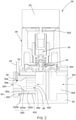
- the gas valve 26 includes a valve body 28, a flow regulator 34, a hot film anemometer 38, and a driver which is a stepper motor 50 as an example.
- the valve body 28 includes a gas inlet 301, a gas outlet 324, an inlet passage 303 communicating with the gas inlet 301, an outlet passage 322 communicating with the gas outlet 324, and an opening 304 disposed between the inlet passage 303 and the outlet passage 322.
- the gas inlet 301 is adapted to be connected to a gas source G, and the gas outlet 324 communicates with the burner 20.
- the gas inlet 301 directly communicates with the gas source G via the gas pipe P, and there is no pressure regulator 14, which is used in a conventional gas appliance, disposed between the gas inlet 301 and the gas source G.
- the valve body 28 includes a main body 30 and a tube 32, wherein the main body 30 includes the gas inlet 301, the inlet passage 303, the opening 304, and a connecting passage 305; the opening 304 is disposed between the inlet passage 303 and the connecting passage 305.
- the tube 32 is connected to the connecting passage 305 and includes the outlet passage 322 and the gas outlet 324.
- the outlet passage 322 includes a first section 322a, a second section 322b, and a third section 322c, wherein the first section 322a is between the second section 322b and the third section 322c.
- the first section 322a is tapered and has an internal diameter which is gradually decreased in a direction from the third section 322c to the second section 322b; the second section 322b is equal-diameter and is between the first section 322a and the gas outlet 324.
- the connecting passage 305 has an internal thread.
- the tube 30 includes a threaded tube 32a and an outer tube 32b which are connected to each other, wherein the threaded tube 32a is engaged with the internal thread of the connecting passage 305; the outer tube 32b includes at least a part of the second section 322b and is disposed outside of the main body 30.
- the hot film anemometer 38 is disposed in the outer tube 32b. More specifically, the outer tube 32b includes a recess 326 which is recessed from a wall of the second section 322b. In this embodiment, the outer tube 32b forms a head which is a hexagon head as an example, and the head is rotatable such that the threaded tube 32a could be screwed to the connecting passage 305.
- a seal ring is disposed between the outer tube 32b and the main body 30 to prevent the gas from leaking out.
- the flow regulator 34 is movably disposed at the opening 304 of the valve body 28.
- the flow regulator 34 is a valve plug as an example, and is connected to a transmission mechanism 36, wherein the transmission mechanism 36 is driven to change an opening degree of the opening 304.
- the hot film anemometer 38 is disposed in the valve body 28.
- the hot film anemometer 38 includes a probe 38a exposed to the outlet passage 322 to sense the gas flow rate passing through the outlet passage 322.
- the hot film anemometer 38 includes a substrate 40, and a hot film resistor 402 and a compensation resistor 404 which are disposed on the substrate 40, wherein the hot film resistor 402 and the compensation resistor 404 are exposed to the outlet passage 322.
- the probe 38a includes the hot film resistor 402 and the compensation resistor 404, and a resistance of the hot film resistor 402 is smaller than a resistance of the compensation resistor 404.
- the probe 38a could only include the hot film resistor 402 exposed to the outlet passage 322.
- the hot film anemometer 38 is disposed in the recess 326, and the probe 38a of the hot film anemometer 38 is exposed to the second section 322b.
- the hot film anemometer 38 is electronically connected to an external circuit via a signal wire 44 extending out of the outer tube 32b of the tube 32.
- Another two resistors 406, 408 are further disposed on the substrate 40 and form a bridge circuit 40a together with the hot film resistor 402 and the compensation resistor 404, wherein each one end of the hot film resistor 402 and the compensation resistor 404 is connected to a first node 421, and the first node 421 is adapted to be connected to a power supply; each one end of the another two resistors 406, 408 is connected to a second node 422, and the second node 422 is adapted to be connected to a grounding terminal.
- the hot film resistor 402 When the power is supplied, the hot film resistor 402 would generate heat, and meanwhile, when the gas flow F passing through the hot film resistor 402 increases, the hot film resistor 402 would be cooled down and the resistance thereof would become small and the current thereof would increase.
- the current of the compensation resistor 404 increases as well, thereby raising the temperature of the hot film resistor 402 again, and vice versa.
- the current of the compensation resistor 404 and the gas flow rate are proportional and corresponding to each other.
- the voltage between a third node 423 and a fourth node 424 of the bridge circuit 40a would be proportional to the gas flow rate.
- the first node 421, the second node 422, the third node 423, and the fourth node 424 are connected to outside of the valve body 28 via the signal wire 44.
- the third node 423 and the fourth node 424 are connected to an amplifying circuit 522, wherein the amplifying circuit 522 is disposed outside of the valve body 28 and adapted to amplify the voltage between the third node 423 and the fourth node 424.
- the amplifying circuit 522 could be disposed on the substrate 40 as well.
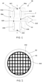
- the gas valve 26 further includes a flow guiding member 48.
- the flow guiding member 48 is disposed in the third section 322c of the outlet passage 322 of the tube 32, and the probe 38a of the hot film anemometer 38 is disposed between the flow guiding member 48 and the gas outlet 324.
- the flow guiding member 48 includes a plurality of sub-passages 482 (as shown in FIG. 3 and FIG. 5 ) which could guide the gas flow F to pass through the probe 38a fluently, thereby reducing a detection error which is caused by the turbulent flow.
- the stepper motor 50 is disposed in the valve body 28 and connected to the flow regulator 34.
- the stepper motor 50 is adapted to receive a control signal to drive the flow regulator 34 to move.
- a rotary shaft 502 of the stepper motor 50 is connected to the flow regulator 34 via the transmission mechanism 36.
- the control device 52 is electronically connected to the ignitor 22, the flame detector 24, the hot film anemometer 38, and the stepper motor 50.
- the control device 52 includes the power supply and the grounding terminal, and is adapted to supply power to the bridge circuit 40a on the substrate 40 of the hot film anemometer 38 via the signal wire 44.
- the control device 52 further includes the amplifying circuit 522 and is electronically connected to the bridge circuit 40a via the signal wire 44 to receive the voltage between the third node 423 and the fourth node 424 of the bridge circuit 40a.
- the control device 52 is adapted to execute a control method for the gas valve 26 in this embodiment.
- the control device 52 would control the ignitor 22 to generate sparks with respect to the burner 10 first.
- control method for the gas valve 26 is executed, wherein the control method includes the following steps, which are shown in FIG. 6 .
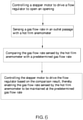
- the control device 52 outputs the control signal to control the stepper motor 50 to drive the flow regulator 34 to open the opening 304 for passing the gas; when the gas is ignited, the control device 52 would be informed of the ignition via an electrical signal sending back from the flame detector 24.
- the hot film anemometer 38 is adapted to sense the gas flow rate in the outlet passage 322; in this embodiment, the control device 52 would convert the voltage output from the bridge circuit 40a of the hot film anemometer 38 into a corresponding gas flow rate.
- the control device 52 is adapted to control the stepper motor 50 to drive the flow regulator 34 by outputting the control signal based on a predetermined gas flow rate and the gas flow rate sensed by the hot film anemometer 38, thereby enabling the gas flow rate sensed by the hot film anemometer 38 to be maintained at the predetermined gas flow rate. More particularly, the control device 52 would compare the gas flow rate sensed by the hot film anemometer 38 with the predetermined gas flow rate, and control the stepper motor 50 to drive the flow regulator 34 based on the comparison result such that the gas flow rate sensed by the hot film anemometer 38 could be maintained at the predetermined gas flow rate.
- the predetermined gas flow rate is corresponding to a predetermined heating value.
- the gas flow rate supplying to the burner 20 is equal to the predetermined gas flow rate, the burner 20 would generate the predetermined heating value.
- the gas flow rate output from the gas valve 26 still could be stably maintained at the predetermined gas flow rate through controlling the flow regulator 34.
- the advantage of the hot film anemometer 38 is that the gas flow rate could be sensed rapidly, hence, the stepper motor 50 could be controlled instantly and the gas flow rate could be maintained at the predetermined gas flow rate rapidly. Since the hot film anemometer 38 is disposed between the opening 304 and the gas outlet 324, the gas flow rate has been regulated by the flow regulator 34 already and the gas flow rate passing through the hot film anemometer 38 would be more stable.
- a gas appliance of a second embodiment according to the present invention has almost the same structure as the gas appliance of the first embodiment, except that the gas appliance provided by the second embodiment further includes a mixer 54 and a blower 56, wherein the mixer 54 is disposed between the gas valve 26 and the burner 20.
- the blower 56 is electronically connected to the control device 52 and a gas outlet of the blower 56 is connected to the mixer 54.
- the control device 52 generates a predetermined rotation speed and a predetermined gas flow rate according to a predetermined heating value, wherein the control device 52 controls a rotation speed of a motor of the blower 56 according to the predetermined rotation speed, and controls the stepper motor 50 to drive the flow regulator 34 according to the predetermined gas flow rate and the gas flow rate sensed by the hot film anemometer 38, thereby enabling the gas flow rate sensed by the hot film anemometer 38 to be maintained at the predetermined gas flow rate.
- a gas valve 58 of a third embodiment is illustrated and has a structure similar to the gas valve 26 of the first embodiment.
- the gas valve 58 includes a valve body 60, a flow regulator 66, a hot film anemometer 68, and a stepper motor 70.
- the valve body 60 provided by this embodiment includes a main body 62 and a tube 64, wherein the main body 62 includes a gas inlet 622, an inlet passage 624, an opening 626, and a connecting passage 628; the tube 64 has the same structure as the tube 32 of the first embodiment, and includes an outlet passage 642 and a gas outlet 644.
- the flow regulator 66 provided by this embodiment is a plug member as an example, and is rotatably disposed in the main body 62.
- the flow regulator 66 includes an axial hole 661, a first hole 662, a second hole 663, a first guiding groove 664, and a second guiding groove 665, wherein the first hole 662 and the second hole 663 communicate with the axial hole 661, and a diameter of the first hole 662 is greater than a diameter of the second hole 663.
- the first guiding groove 664 and the second guiding groove 665 are disposed between the first hole 662 and the second hole 663; one end of the first guiding groove 664 is connected to the first hole 662, and one end of the second guiding groove 665 is connected to the second hole 663.
- the flow regulator 66 could only include the axial hole 661, the first hole 662, and the first guiding groove 664.
- the hot film anemometer 68 is disposed in the valve body 60.
- the stepper motor 70 is disposed with the main body 62, and a rotary shaft 702 of the stepper motor 70 is connected to the plug member.
- the gas valve 58 provided by this embodiment could be adapted to the gas appliance 2 of the first embodiment as well.
- a gas valve 72 of a fourth embodiment according to the present invention has almost the same structure as the gas valve 26 of the first embodiment, except that a first section 742a and a second section 742b of an outlet passage 742 of a tube 74 have identical internal diameters, that is, the outlet passage 742 between a flow guiding member 76 and the hot film anemometer 38 has an equal internal diameter.
- the gas flow F could pass through the probe 38a of the hot film anemometer 38 more stably.
- a gas valve 78 of a fifth embodiment has almost the same structure as the gas valve 26 of the first embodiment, except that a first section 802a and a second section 802b of an outlet passage 802 of a tube 80 have identical internal diameters, while a third section 802c is tapered, and a flow guiding member 82 is disposed in the first section 802a.
- the outlet passage 802 between the flow guiding member 82 and the hot film anemometer 38 has an equal internal diameter. Whereby, the gas flow F could pass through the probe 38a of the hot film anemometer 38 more stably as well.
- the outlet passage 642 of the tube 64 of the third embodiment also could adopt the structures of the tube 74, 80 of the fourth and the fifth embodiments.
- the driver of each of the aforementioned embodiments is a stepper motor as an example.
- the gas valve could also be a proportional valve as an example, as disclosed in United States patent publication number US20090206291A1 .
- a driver of the proportional valve includes a coil and a magnet, which could drive a flow regulator to change an opening degree of an opening via an electromagnetic force.
- the variation of the gas flow rate could be sensed accurately and rapidly by disposing the hot film anemometer in the outlet passage, whereby to control the stepper motor and stabilize the gas flow rate passing through the gas valve without disposing the pressure regulator.
- the gas flow rate could be controlled more accurately and the manufacturing cost of the gas appliance could be reduced.
Landscapes
- Engineering & Computer Science (AREA)
- Chemical & Material Sciences (AREA)
- Combustion & Propulsion (AREA)
- Mechanical Engineering (AREA)
- General Engineering & Computer Science (AREA)
- Feeding And Controlling Fuel (AREA)
- Measuring Volume Flow (AREA)
Description
- The present invention is related to a gas appliance, and more particularly to a gas valve which could stabilize a gas flow rate.
- Gas appliances are usually utilized as heating devices. As comparing to electro-thermal heating devices, the gas appliances provide more heat energy by burning gas. In addition, the gas appliances also have a heating time and a response time which are faster than the electro-thermal heating devices.
- Referring to
FIG. 1 , aconventional gas appliance 1 includes aburner 10, agas valve 12, and apressure regulator 14, wherein theburner 10 is adapted to burn gas to generate flames; thegas valve 12 communicates with theburner 10 and is adapted to regulate a gas flow rate supplying to theburner 10 manually or automatically; one end of thepressure regulator 14 is connected to thegas valve 12, and another end of thepressure regulator 14 is connected to a gas source 16 (e.g. liquefied petroleum gas or natural gas). - It is required for the
conventional gas appliance 1 to utilize thepressure regulator 14 to stabilize a pressure output from thegas source 16 to thegas valve 12. - However, when the pressure output from the
gas source 16 is smaller than a certain pressure, the pressure output from thepressure regulator 14 would be unstable. Since thegas valve 12 is adapted to regulate the gas flow rate by changing an opening degree of an opening, the gas flow rate would be unstable when the pressure supplying to thegas valve 12 is unstable, thereby affecting the combustion efficiency of theburner 10. - Patent document
EP 0 064 560 A1 discloses a safety shut-off valve for automatically shutting off the supply of fluids or gases in case of an emergency. For this purpose, the safety shut-off valve comprises an electromagnetic transference device for forcibly transferring fluid from an admission port into a pressure chamber through an exhaust post by means of electromagnetic force, a main valve device consisting of a responsive body in response to the pressure in said pressure chamber and a main valve body connected with said responsive body, and an opening and closing means for controlling the opening and closing of a branch path for discharging the fluid in said pressure chamber. - In view of the above, an object of the present invention is to provide a gas valve which could stabilize a gas flow rate and sense the gas flow rate more accurately.
- To achieve the object mentioned above, the present invention provides a gas valve including a valve body, a flow regulator, a hot film anemometer, and a driver, wherein the valve body includes a gas inlet, a gas outlet, an inlet passage communicating with the gas inlet, an outlet passage communicating with the gas outlet, and an opening disposed between the inlet passage and the outlet passage; the flow regulator is movably disposed at the opening of the valve body and is driven to change an opening degree of the opening; the hot film anemometer is disposed in the valve body and includes a probe which includes a hot film resistor exposed to the outlet passage to sense a gas flow rate passing through the outlet passage; the driver is disposed in the valve body and connected to the flow regulator, and is adapted to receive a control signal to drive the flow regulator to move. According to the invention, the gas valve further comprises a flow guiding member disposed in the outlet passage, wherein the probe of the hot film anemometer is disposed between the flow guiding member and the gas outlet.
- The advantage of the present invention is that a variation of the gas flow rate could be sensed accurately and rapidly by disposing the hot film anemometer in the outlet passage, whereby to control the stepper motor and stabilize the gas flow rate passing through the gas valve without disposing the pressure regulator. In this way, the gas flow rate could be controlled more accurately and the manufacturing cost of the gas appliance could be reduced.
- The present invention will be best understood by referring to the following detailed description of some illustrative embodiments in conjunction with the accompanying drawings, in which:
-
FIG. 1 is a schematic view showing a conventional gas appliance; -
FIG. 2 is a schematic view showing a gas appliance of a first embodiment according to the present invention; -
FIG. 3 is a schematic view showing the gas valve of the gas appliance ofFIG. 2 ; -
FIG. 4 is a schematic view showing the hot film anemometer of the gas appliance ofFIG. 2 ; -
FIG. 5 is a schematic view showing that the flow guiding member is disposed in the tube according to the embodiment ofFIG. 2 ; -
FIG. 6 is a flowchart of a control method for the gas valve ofFIG. 2 ; -
FIG. 7 is a schematic view showing a gas appliance of a second embodiment according to the present invention; -
FIG. 8 is a schematic view showing a gas valve of a third embodiment according to the present invention; -
FIG. 9 and FIG. 10 are perspective views of the flow regulator of the third embodiment according to the present invention; -
FIG. 11 is a schematic view showing a gas valve of a fourth embodiment according to the present invention; and -
FIG. 12 is a schematic view showing a gas valve of a fifth embodiment according to the present invention. - The following illustrative embodiments and drawings are provided to illustrate the disclosure of the present invention, these and other advantages and effects can be clearly understood by persons skilled in the art after reading the disclosure of this specification. As shown in
FIG. 2 to FIG. 5 , agas appliance 2 of a first embodiment according to the present invention includes aburner 20, anignitor 22, aflame detector 24, agas valve 26, and acontrol device 52. In this embodiment, thegas appliance 2 could be a gas heating device such as a gas stove, a fireplace, or a water heater for example. - The
burner 20 is adapted to burn gas to generate flames. Theignitor 22 is disposed adjacent to theburner 20 and is controllable to generate sparks with respect to theburner 20 so as to ignite the gas output from theburner 20. Theflame detector 24 is disposed adjacent to theburner 20 to detect the flames. Theflame detector 24 could be a thermocouple or a flame sensor as an example. - The
gas valve 26 is disposed on a gas pipe P which communicates with theburner 20. Thegas valve 26 is controllable to open and block the gas pipe P and regulate the gas flow rate supplying to theburner 20. In this embodiment, thegas valve 26 includes avalve body 28, aflow regulator 34, ahot film anemometer 38, and a driver which is astepper motor 50 as an example. Wherein, thevalve body 28 includes agas inlet 301, agas outlet 324, aninlet passage 303 communicating with thegas inlet 301, anoutlet passage 322 communicating with thegas outlet 324, and anopening 304 disposed between theinlet passage 303 and theoutlet passage 322. Wherein, thegas inlet 301 is adapted to be connected to a gas source G, and thegas outlet 324 communicates with theburner 20. In this embodiment, thegas inlet 301 directly communicates with the gas source G via the gas pipe P, and there is nopressure regulator 14, which is used in a conventional gas appliance, disposed between thegas inlet 301 and the gas source G. - In this embodiment, the
valve body 28 includes amain body 30 and atube 32, wherein themain body 30 includes thegas inlet 301, theinlet passage 303, the opening 304, and a connectingpassage 305; theopening 304 is disposed between theinlet passage 303 and the connectingpassage 305. Thetube 32 is connected to the connectingpassage 305 and includes theoutlet passage 322 and thegas outlet 324. Theoutlet passage 322 includes afirst section 322a, asecond section 322b, and athird section 322c, wherein thefirst section 322a is between thesecond section 322b and thethird section 322c. Thefirst section 322a is tapered and has an internal diameter which is gradually decreased in a direction from thethird section 322c to thesecond section 322b; thesecond section 322b is equal-diameter and is between thefirst section 322a and thegas outlet 324. - The connecting
passage 305 has an internal thread. Thetube 30 includes a threadedtube 32a and anouter tube 32b which are connected to each other, wherein the threadedtube 32a is engaged with the internal thread of the connectingpassage 305; theouter tube 32b includes at least a part of thesecond section 322b and is disposed outside of themain body 30. Thehot film anemometer 38 is disposed in theouter tube 32b. More specifically, theouter tube 32b includes arecess 326 which is recessed from a wall of thesecond section 322b. In this embodiment, theouter tube 32b forms a head which is a hexagon head as an example, and the head is rotatable such that the threadedtube 32a could be screwed to the connectingpassage 305. A seal ring is disposed between theouter tube 32b and themain body 30 to prevent the gas from leaking out. - The
flow regulator 34 is movably disposed at the opening 304 of thevalve body 28. In this embodiment, theflow regulator 34 is a valve plug as an example, and is connected to atransmission mechanism 36, wherein thetransmission mechanism 36 is driven to change an opening degree of theopening 304. - Referring to
FIG. 3 andFIG. 4 , thehot film anemometer 38 is disposed in thevalve body 28. Thehot film anemometer 38 includes aprobe 38a exposed to theoutlet passage 322 to sense the gas flow rate passing through theoutlet passage 322. In this embodiment, thehot film anemometer 38 includes asubstrate 40, and ahot film resistor 402 and acompensation resistor 404 which are disposed on thesubstrate 40, wherein thehot film resistor 402 and thecompensation resistor 404 are exposed to theoutlet passage 322. Theprobe 38a includes thehot film resistor 402 and thecompensation resistor 404, and a resistance of thehot film resistor 402 is smaller than a resistance of thecompensation resistor 404. - In practice, the
probe 38a could only include thehot film resistor 402 exposed to theoutlet passage 322. In this embodiment, thehot film anemometer 38 is disposed in therecess 326, and theprobe 38a of thehot film anemometer 38 is exposed to thesecond section 322b. Thehot film anemometer 38 is electronically connected to an external circuit via asignal wire 44 extending out of theouter tube 32b of thetube 32. - Another two
resistors substrate 40 and form abridge circuit 40a together with thehot film resistor 402 and thecompensation resistor 404, wherein each one end of thehot film resistor 402 and thecompensation resistor 404 is connected to afirst node 421, and thefirst node 421 is adapted to be connected to a power supply; each one end of the another tworesistors second node 422, and thesecond node 422 is adapted to be connected to a grounding terminal. When the power is supplied, thehot film resistor 402 would generate heat, and meanwhile, when the gas flow F passing through thehot film resistor 402 increases, thehot film resistor 402 would be cooled down and the resistance thereof would become small and the current thereof would increase. In order to balance thebridge circuit 40a, the current of thecompensation resistor 404 increases as well, thereby raising the temperature of thehot film resistor 402 again, and vice versa. Whereby, the current of thecompensation resistor 404 and the gas flow rate are proportional and corresponding to each other. Hence, the voltage between athird node 423 and afourth node 424 of thebridge circuit 40a would be proportional to the gas flow rate. In this embodiment, thefirst node 421, thesecond node 422, thethird node 423, and thefourth node 424 are connected to outside of thevalve body 28 via thesignal wire 44. Thethird node 423 and thefourth node 424 are connected to anamplifying circuit 522, wherein the amplifyingcircuit 522 is disposed outside of thevalve body 28 and adapted to amplify the voltage between thethird node 423 and thefourth node 424. In practice, the amplifyingcircuit 522 could be disposed on thesubstrate 40 as well. - In order to sense the gas flow rate more accurately, the
gas valve 26 according to the invention further includes aflow guiding member 48. Theflow guiding member 48 is disposed in thethird section 322c of theoutlet passage 322 of thetube 32, and theprobe 38a of thehot film anemometer 38 is disposed between theflow guiding member 48 and thegas outlet 324. Theflow guiding member 48 includes a plurality of sub-passages 482 (as shown inFIG. 3 andFIG. 5 ) which could guide the gas flow F to pass through theprobe 38a fluently, thereby reducing a detection error which is caused by the turbulent flow. - The
stepper motor 50 is disposed in thevalve body 28 and connected to theflow regulator 34. Thestepper motor 50 is adapted to receive a control signal to drive theflow regulator 34 to move. In this embodiment, arotary shaft 502 of thestepper motor 50 is connected to theflow regulator 34 via thetransmission mechanism 36. When therotary shaft 502 of thestepper motor 50 is rotated clockwise or counterclockwise, theflow regulator 34 would be driven to move along an axial direction of therotary shaft 502, thereby changing the opening degree of theopening 304. - The
control device 52 is electronically connected to theignitor 22, theflame detector 24, thehot film anemometer 38, and thestepper motor 50. In this embodiment, thecontrol device 52 includes the power supply and the grounding terminal, and is adapted to supply power to thebridge circuit 40a on thesubstrate 40 of thehot film anemometer 38 via thesignal wire 44. Thecontrol device 52 further includes the amplifyingcircuit 522 and is electronically connected to thebridge circuit 40a via thesignal wire 44 to receive the voltage between thethird node 423 and thefourth node 424 of thebridge circuit 40a. - The
control device 52 is adapted to execute a control method for thegas valve 26 in this embodiment. When thegas appliance 2 is idle (that is, theopening 304 is closed), before executing the control method, thecontrol device 52 would control theignitor 22 to generate sparks with respect to theburner 10 first. - Then, the control method for the
gas valve 26 is executed, wherein the control method includes the following steps, which are shown inFIG. 6 . - The
control device 52 outputs the control signal to control thestepper motor 50 to drive theflow regulator 34 to open theopening 304 for passing the gas; when the gas is ignited, thecontrol device 52 would be informed of the ignition via an electrical signal sending back from theflame detector 24. - The
hot film anemometer 38 is adapted to sense the gas flow rate in theoutlet passage 322; in this embodiment, thecontrol device 52 would convert the voltage output from thebridge circuit 40a of thehot film anemometer 38 into a corresponding gas flow rate. - The
control device 52 is adapted to control thestepper motor 50 to drive theflow regulator 34 by outputting the control signal based on a predetermined gas flow rate and the gas flow rate sensed by thehot film anemometer 38, thereby enabling the gas flow rate sensed by thehot film anemometer 38 to be maintained at the predetermined gas flow rate. More particularly, thecontrol device 52 would compare the gas flow rate sensed by thehot film anemometer 38 with the predetermined gas flow rate, and control thestepper motor 50 to drive theflow regulator 34 based on the comparison result such that the gas flow rate sensed by thehot film anemometer 38 could be maintained at the predetermined gas flow rate. - In this embodiment, the predetermined gas flow rate is corresponding to a predetermined heating value. When the gas flow rate supplying to the
burner 20 is equal to the predetermined gas flow rate, theburner 20 would generate the predetermined heating value. - Whereby, even the pressure output from the gas source G is unstable or too small, resulting in a variation of the gas flow rate, the gas flow rate output from the
gas valve 26 still could be stably maintained at the predetermined gas flow rate through controlling theflow regulator 34. The advantage of thehot film anemometer 38 is that the gas flow rate could be sensed rapidly, hence, thestepper motor 50 could be controlled instantly and the gas flow rate could be maintained at the predetermined gas flow rate rapidly. Since thehot film anemometer 38 is disposed between theopening 304 and thegas outlet 324, the gas flow rate has been regulated by theflow regulator 34 already and the gas flow rate passing through thehot film anemometer 38 would be more stable. - As shown in
FIG. 7 , a gas appliance of a second embodiment according to the present invention has almost the same structure as the gas appliance of the first embodiment, except that the gas appliance provided by the second embodiment further includes amixer 54 and ablower 56, wherein themixer 54 is disposed between thegas valve 26 and theburner 20. Theblower 56 is electronically connected to thecontrol device 52 and a gas outlet of theblower 56 is connected to themixer 54. Thecontrol device 52 generates a predetermined rotation speed and a predetermined gas flow rate according to a predetermined heating value, wherein thecontrol device 52 controls a rotation speed of a motor of theblower 56 according to the predetermined rotation speed, and controls thestepper motor 50 to drive theflow regulator 34 according to the predetermined gas flow rate and the gas flow rate sensed by thehot film anemometer 38, thereby enabling the gas flow rate sensed by thehot film anemometer 38 to be maintained at the predetermined gas flow rate. - As shown in
FIG. 8 to FIG. 10 , agas valve 58 of a third embodiment according to the present invention is illustrated and has a structure similar to thegas valve 26 of the first embodiment. Thegas valve 58 includes avalve body 60, aflow regulator 66, ahot film anemometer 68, and astepper motor 70. Thevalve body 60 provided by this embodiment includes amain body 62 and atube 64, wherein themain body 62 includes agas inlet 622, aninlet passage 624, anopening 626, and a connectingpassage 628; thetube 64 has the same structure as thetube 32 of the first embodiment, and includes anoutlet passage 642 and agas outlet 644. Theflow regulator 66 provided by this embodiment is a plug member as an example, and is rotatably disposed in themain body 62. Theflow regulator 66 includes anaxial hole 661, afirst hole 662, asecond hole 663, afirst guiding groove 664, and asecond guiding groove 665, wherein thefirst hole 662 and thesecond hole 663 communicate with theaxial hole 661, and a diameter of thefirst hole 662 is greater than a diameter of thesecond hole 663. Thefirst guiding groove 664 and thesecond guiding groove 665 are disposed between thefirst hole 662 and thesecond hole 663; one end of thefirst guiding groove 664 is connected to thefirst hole 662, and one end of thesecond guiding groove 665 is connected to thesecond hole 663. In practice, theflow regulator 66 could only include theaxial hole 661, thefirst hole 662, and thefirst guiding groove 664. - Similar to the first embodiment, the
hot film anemometer 68 is disposed in thevalve body 60. Thestepper motor 70 is disposed with themain body 62, and arotary shaft 702 of thestepper motor 70 is connected to the plug member. Whereby, thegas valve 58 provided by this embodiment could be adapted to thegas appliance 2 of the first embodiment as well. - As shown in
FIG. 11 , agas valve 72 of a fourth embodiment according to the present invention has almost the same structure as thegas valve 26 of the first embodiment, except that afirst section 742a and asecond section 742b of anoutlet passage 742 of atube 74 have identical internal diameters, that is, theoutlet passage 742 between aflow guiding member 76 and thehot film anemometer 38 has an equal internal diameter. Whereby, the gas flow F could pass through theprobe 38a of thehot film anemometer 38 more stably. - As shown in
FIG. 12 , agas valve 78 of a fifth embodiment according to the present invention has almost the same structure as thegas valve 26 of the first embodiment, except that afirst section 802a and asecond section 802b of anoutlet passage 802 of atube 80 have identical internal diameters, while athird section 802c is tapered, and aflow guiding member 82 is disposed in thefirst section 802a. Theoutlet passage 802 between theflow guiding member 82 and thehot film anemometer 38 has an equal internal diameter. Whereby, the gas flow F could pass through theprobe 38a of thehot film anemometer 38 more stably as well. - The
outlet passage 642 of thetube 64 of the third embodiment also could adopt the structures of thetube - The driver of each of the aforementioned embodiments is a stepper motor as an example. In practice, the gas valve could also be a proportional valve as an example, as disclosed in United States patent publication number
US20090206291A1 . A driver of the proportional valve includes a coil and a magnet, which could drive a flow regulator to change an opening degree of an opening via an electromagnetic force. - According to the illustration mentioned above, the variation of the gas flow rate could be sensed accurately and rapidly by disposing the hot film anemometer in the outlet passage, whereby to control the stepper motor and stabilize the gas flow rate passing through the gas valve without disposing the pressure regulator. In this way, the gas flow rate could be controlled more accurately and the manufacturing cost of the gas appliance could be reduced.
- It must be pointed out that the embodiments described above are only some embodiments of the present invention. All equivalent structures which employ the concepts disclosed in this specification and the appended claims should fall within the scope of the present invention.
Claims (8)
- A gas valve (26, 58, 72, 78), comprising:a valve body (28, 60), including a gas inlet (301, 622), a gas outlet (324, 644), an inlet passage (303, 624) communicating with the gas inlet (301, 622), an outlet passage (322, 642, 742, 802) communicating with the gas outlet (324, 644), and an opening (304, 626) disposed between the inlet passage (303, 624) and the outlet passage (322, 642, 742, 802);a flow regulator (34, 66), being movably disposed at the opening (304, 626) of the valve body (28, 60), wherein the flow regulator (34, 66) is driven to change an opening degree of the opening (304, 626);a hot film anemometer (38, 68), disposed in the valve body (28, 60), wherein the hot film anemometer (38, 68) includes a probe (38a) which includes a hot film resistor (402) exposed to the outlet passage (322, 642, 742, 802) to sense a gas flow rate passing through the outlet passage (322, 642, 742, 802); anda driver, disposed in the valve body (28, 60) and connected to the flow regulator (34, 66), wherein the driver is adapted to receive a control signal to drive the flow regulator (34, 66) to move,characterized in thatthe gas valve (26, 58, 72, 78) further comprises a flow guiding member (48, 76, 82) disposed in the outlet passage (322, 642, 742, 802); and thatthe probe (38a) of the hot film anemometer (38, 68) is disposed between the flow guiding member (48, 76, 82) and the gas outlet (324, 644).
- The gas valve (26, 58, 72, 78) of claim 1, wherein the hot film anemometer (38, 68) further includes a substrate (40), and the hot film resistor (402) is disposed on the substrate (40).
- The gas valve (26, 58, 72, 78) of claim 1, wherein the flow guiding member (48, 76, 82) further includes a plurality of sub-passages (482).
- The gas valve (26, 58, 72, 78) of claim 1, wherein the outlet passage (322, 642, 742, 802) further includes a first section (322a, 742a, 802a) and a second section (322b, 742b, 802b), wherein the first section (322a, 742a, 802a) is between the flow guiding member (48, 76, 82) and the second section (322b, 742b, 802b), and the second section (322b, 742b, 802b) is between the first section (322a, 742a, 802a) and the gas outlet (324, 644); the probe (38a) of the hot film anemometer (38, 68) is disposed in the second section (322b, 742b, 802b).
- The gas valve (72, 78) of claim 4, wherein the first section (742a, 802a) and the second section (742b, 802b) of the outlet passage (742, 802) have identical internal diameters.
- The gas valve (26, 58, 72, 78) of claim 4, wherein the valve body (28, 60) further includes a main body (30, 62) and a tube (32, 64, 74, 80); the main body (30, 62) includes the gas inlet (301, 622), the inlet passage (303, 624), the opening (304, 626), and a connecting passage (305, 628), wherein the opening (304, 626) is disposed between the inlet passage (303, 624) and the connecting passage (305, 628); the tube (32, 64, 74, 80) is connected to the connecting passage (305, 628) and includes the outlet passage (322, 642, 742, 802) and the gas outlet (324, 644); the hot film anemometer (38, 68) is disposed in the tube (32, 64, 74, 80).
- The gas valve (26, 58, 72, 78) of claim 6, wherein the tube (32, 64, 74, 80) includes a threaded tube (32a) and an outer tube (32b) which are connected to each other; the connecting passage (305, 628) has an internal thread to be engaged with the threaded tube (32a); the outer tube (32b) includes at least a part of the second section (322b, 742b, 802b) and is disposed outside of the main body (30, 62); the hot film anemometer (38, 68) is disposed in the outer tube (32b).
- The gas valve (26, 58, 72, 78) of claim 7, wherein the outer tube (32b) further includes a recess (326) which is recessed from a wall of the second section (322b, 742b, 802b); the hot film anemometer (38, 68) is disposed in the recess (326).
Applications Claiming Priority (1)
| Application Number | Priority Date | Filing Date | Title |
|---|---|---|---|
| TW107102681A TWI669464B (en) | 2018-01-25 | 2018-01-25 | Gas appliance, gas valve and control method thereof |
Publications (2)
| Publication Number | Publication Date |
|---|---|
| EP3517841A1 EP3517841A1 (en) | 2019-07-31 |
| EP3517841B1 true EP3517841B1 (en) | 2022-02-16 |
Family
ID=62814828
Family Applications (1)
| Application Number | Title | Priority Date | Filing Date |
|---|---|---|---|
| EP18180056.6A Active EP3517841B1 (en) | 2018-01-25 | 2018-06-27 | Gas valve |
Country Status (3)
| Country | Link |
|---|---|
| US (1) | US11060724B2 (en) |
| EP (1) | EP3517841B1 (en) |
| TW (1) | TWI669464B (en) |
Families Citing this family (5)
| Publication number | Priority date | Publication date | Assignee | Title |
|---|---|---|---|---|
| US8008386B2 (en) | 2006-12-25 | 2011-08-30 | Kaneka Corporation | Curable composition |
| US10871235B1 (en) | 2019-08-07 | 2020-12-22 | Grand Mate Co., Ltd. | Flow regulating valve of gas stove |
| EP3779279B1 (en) * | 2019-08-13 | 2022-03-09 | Grand Mate Co., Ltd. | Flow regulating valve of gas stove |
| US11732890B2 (en) | 2020-09-30 | 2023-08-22 | Midea Group Co., Ltd. | Cooking appliance gas oven burner control during oven warm-up operation |
| US11739933B2 (en) | 2020-09-30 | 2023-08-29 | Midea Group Co., Ltd. | Oven broiler gas burner for cooking appliance with variable electromechanical valve |
Family Cites Families (24)
| Publication number | Priority date | Publication date | Assignee | Title |
|---|---|---|---|---|
| US4463773A (en) | 1980-11-21 | 1984-08-07 | Yamatake-Honeywell Co., Ltd. | Safety shut-off valve |
| US5762880A (en) | 1996-12-16 | 1998-06-09 | Megtec Systems, Inc. | Operational process and its improved control system of a secondary air burner |
| JP3385307B2 (en) * | 1998-05-11 | 2003-03-10 | 三菱電機株式会社 | Flow sensor |
| DE19824521B4 (en) * | 1998-06-02 | 2004-12-23 | Honeywell B.V. | Control device for gas burners |
| DE10027831C2 (en) * | 2000-06-05 | 2002-08-01 | Siemens Ag | Mass flow meter |
| CN2777389Y (en) * | 2005-02-05 | 2006-05-03 | 叶克斌 | Automatic controller for gas range |
| US20100170483A1 (en) * | 2007-04-26 | 2010-07-08 | Heraeus Sensor Technology Gmbh | Film resistor in an exhaust-gas pipe |
| TW200925522A (en) * | 2007-12-07 | 2009-06-16 | Yi-Hua Huang | Flow calibrating method for gas regulating valve and calibrating step thereof |
| TW200936960A (en) | 2008-02-20 | 2009-09-01 | Grand Mate Co Ltd | LPG flow rate control valve |
| CN102353806B (en) | 2011-06-24 | 2012-09-05 | 清华大学 | Temperature compensation circuit and method thereof for heat-sensitive flow rate sensor, and automatic adjusting method for power of heat-sensitive flow rate sensor |
| CN102954500A (en) | 2011-08-26 | 2013-03-06 | 关隆股份有限公司 | Gas appliance and method for adjusting and controlling same |
| DE102011117736A1 (en) | 2011-11-07 | 2013-05-08 | Honeywell Technologies Sarl | Method for operating a gas burner |
| JPWO2013099916A1 (en) * | 2011-12-28 | 2015-05-07 | 川崎重工業株式会社 | Flow velocity distribution homogenizer |
| DE102012102094A1 (en) * | 2012-03-13 | 2013-09-19 | Pierburg Gmbh | Device for determining a gas mass flow and method for recalibrating such a device |
| CN103867765A (en) | 2012-12-10 | 2014-06-18 | 关隆股份有限公司 | Gas control valve and gas burning appliance using gas control valve |
| US9857805B2 (en) * | 2013-02-18 | 2018-01-02 | Flo Technologies, Inc. | Fluid monitoring and control system |
| US9477237B2 (en) * | 2013-06-03 | 2016-10-25 | Tescom Corporation | Pilot operated gas regulator with diaphragm protection |
| TWI567347B (en) * | 2013-10-18 | 2017-01-21 | Grand Mate Co Ltd | Gas regulator |
| CN104633131B (en) | 2013-11-07 | 2017-10-20 | 关隆股份有限公司 | Gas pressure regulator |
| CN105402766B (en) | 2014-09-10 | 2018-09-11 | 关隆股份有限公司 | Gas valve control method for gas |
| US9863639B2 (en) | 2015-08-28 | 2018-01-09 | Grand Mate, Co., Ltd. | Method for controlling gas-fired appliance |
| CN106641310B (en) | 2015-11-02 | 2019-11-15 | 关隆股份有限公司 | Gas valve closes son |
| US10274353B2 (en) * | 2017-03-22 | 2019-04-30 | A. O. Smith Corporation | Flow sensor with hot film anemometer |
| CN208041252U (en) | 2018-03-20 | 2018-11-02 | 关隆股份有限公司 | Gas and gas valve |
-
2018
- 2018-01-25 TW TW107102681A patent/TWI669464B/en active
- 2018-06-21 US US16/014,174 patent/US11060724B2/en active Active
- 2018-06-27 EP EP18180056.6A patent/EP3517841B1/en active Active
Also Published As
| Publication number | Publication date |
|---|---|
| US11060724B2 (en) | 2021-07-13 |
| EP3517841A1 (en) | 2019-07-31 |
| TWI669464B (en) | 2019-08-21 |
| TW201932760A (en) | 2019-08-16 |
| US20190226678A1 (en) | 2019-07-25 |
Similar Documents
| Publication | Publication Date | Title |
|---|---|---|
| EP3517841B1 (en) | Gas valve | |
| CN106642711B (en) | Dual sensing combustion system | |
| US5685707A (en) | Integrated burner assembly | |
| US7252502B2 (en) | Method and system for combined standing pilot safety and temperature setting | |
| EP4400767A2 (en) | Closed-loop programming and control of a combustion appliance | |
| US10161627B2 (en) | Modulating burner with venturi damper | |
| US8230825B2 (en) | Boiler control system | |
| US20080124668A1 (en) | Systems and methods for controlling gas pressure to gas-fired appliances | |
| US7435081B2 (en) | Method and system for pilot light safety | |
| KR102357244B1 (en) | Device for controlling the combustion of a burner | |
| EP3217114B1 (en) | Method and controller for operating a boiler appliance | |
| TWM562369U (en) | Gas appliance and gas valve | |
| US20080293000A1 (en) | Variable orifice gas flow modulating valve | |
| KR0157359B1 (en) | Gas combustion device | |
| CN101115955A (en) | System and method for controlling proper combustion ratio of oil burner by using air pressure sensor | |
| KR100192924B1 (en) | Combustion apparatus | |
| CN116263246A (en) | gas burner | |
| JP2939135B2 (en) | Gas combustion equipment | |
| CN115493165B (en) | Gas appliance and control method thereof | |
| KR910004775B1 (en) | Controller for gas fueled heating apparatus | |
| CN118742771A (en) | Combustible gas mixture delivery device and method | |
| CN110307371A (en) | Gas and gas valve and its control method | |
| TWI546503B (en) | Gas valve control method for gas appliance | |
| JP2016183797A (en) | Combustion equipment | |
| HK1232586A1 (en) | Modulating burner with venturi damper |
Legal Events
| Date | Code | Title | Description |
|---|---|---|---|
| PUAI | Public reference made under article 153(3) epc to a published international application that has entered the european phase |
Free format text: ORIGINAL CODE: 0009012 |
|
| STAA | Information on the status of an ep patent application or granted ep patent |
Free format text: STATUS: THE APPLICATION HAS BEEN PUBLISHED |
|
| AK | Designated contracting states |
Kind code of ref document: A1 Designated state(s): AL AT BE BG CH CY CZ DE DK EE ES FI FR GB GR HR HU IE IS IT LI LT LU LV MC MK MT NL NO PL PT RO RS SE SI SK SM TR |
|
| AX | Request for extension of the european patent |
Extension state: BA ME |
|
| STAA | Information on the status of an ep patent application or granted ep patent |
Free format text: STATUS: REQUEST FOR EXAMINATION WAS MADE |
|
| 17P | Request for examination filed |
Effective date: 20200124 |
|
| RBV | Designated contracting states (corrected) |
Designated state(s): AL AT BE BG CH CY CZ DE DK EE ES FI FR GB GR HR HU IE IS IT LI LT LU LV MC MK MT NL NO PL PT RO RS SE SI SK SM TR |
|
| GRAP | Despatch of communication of intention to grant a patent |
Free format text: ORIGINAL CODE: EPIDOSNIGR1 |
|
| STAA | Information on the status of an ep patent application or granted ep patent |
Free format text: STATUS: GRANT OF PATENT IS INTENDED |
|
| INTG | Intention to grant announced |
Effective date: 20210906 |
|
| GRAS | Grant fee paid |
Free format text: ORIGINAL CODE: EPIDOSNIGR3 |
|
| GRAA | (expected) grant |
Free format text: ORIGINAL CODE: 0009210 |
|
| STAA | Information on the status of an ep patent application or granted ep patent |
Free format text: STATUS: THE PATENT HAS BEEN GRANTED |
|
| AK | Designated contracting states |
Kind code of ref document: B1 Designated state(s): AL AT BE BG CH CY CZ DE DK EE ES FI FR GB GR HR HU IE IS IT LI LT LU LV MC MK MT NL NO PL PT RO RS SE SI SK SM TR |
|
| REG | Reference to a national code |
Ref country code: GB Ref legal event code: FG4D |
|
| REG | Reference to a national code |
Ref country code: CH Ref legal event code: EP |
|
| REG | Reference to a national code |
Ref country code: DE Ref legal event code: R096 Ref document number: 602018030814 Country of ref document: DE |
|
| REG | Reference to a national code |
Ref country code: AT Ref legal event code: REF Ref document number: 1469099 Country of ref document: AT Kind code of ref document: T Effective date: 20220315 |
|
| REG | Reference to a national code |
Ref country code: IE Ref legal event code: FG4D |
|
| REG | Reference to a national code |
Ref country code: LT Ref legal event code: MG9D |
|
| REG | Reference to a national code |
Ref country code: NL Ref legal event code: MP Effective date: 20220216 |
|
| REG | Reference to a national code |
Ref country code: AT Ref legal event code: MK05 Ref document number: 1469099 Country of ref document: AT Kind code of ref document: T Effective date: 20220216 |
|
| PG25 | Lapsed in a contracting state [announced via postgrant information from national office to epo] |
Ref country code: SE Free format text: LAPSE BECAUSE OF FAILURE TO SUBMIT A TRANSLATION OF THE DESCRIPTION OR TO PAY THE FEE WITHIN THE PRESCRIBED TIME-LIMIT Effective date: 20220216 Ref country code: RS Free format text: LAPSE BECAUSE OF FAILURE TO SUBMIT A TRANSLATION OF THE DESCRIPTION OR TO PAY THE FEE WITHIN THE PRESCRIBED TIME-LIMIT Effective date: 20220216 Ref country code: PT Free format text: LAPSE BECAUSE OF FAILURE TO SUBMIT A TRANSLATION OF THE DESCRIPTION OR TO PAY THE FEE WITHIN THE PRESCRIBED TIME-LIMIT Effective date: 20220616 Ref country code: NO Free format text: LAPSE BECAUSE OF FAILURE TO SUBMIT A TRANSLATION OF THE DESCRIPTION OR TO PAY THE FEE WITHIN THE PRESCRIBED TIME-LIMIT Effective date: 20220516 Ref country code: NL Free format text: LAPSE BECAUSE OF FAILURE TO SUBMIT A TRANSLATION OF THE DESCRIPTION OR TO PAY THE FEE WITHIN THE PRESCRIBED TIME-LIMIT Effective date: 20220216 Ref country code: LT Free format text: LAPSE BECAUSE OF FAILURE TO SUBMIT A TRANSLATION OF THE DESCRIPTION OR TO PAY THE FEE WITHIN THE PRESCRIBED TIME-LIMIT Effective date: 20220216 Ref country code: HR Free format text: LAPSE BECAUSE OF FAILURE TO SUBMIT A TRANSLATION OF THE DESCRIPTION OR TO PAY THE FEE WITHIN THE PRESCRIBED TIME-LIMIT Effective date: 20220216 Ref country code: ES Free format text: LAPSE BECAUSE OF FAILURE TO SUBMIT A TRANSLATION OF THE DESCRIPTION OR TO PAY THE FEE WITHIN THE PRESCRIBED TIME-LIMIT Effective date: 20220216 Ref country code: BG Free format text: LAPSE BECAUSE OF FAILURE TO SUBMIT A TRANSLATION OF THE DESCRIPTION OR TO PAY THE FEE WITHIN THE PRESCRIBED TIME-LIMIT Effective date: 20220516 |
|
| PG25 | Lapsed in a contracting state [announced via postgrant information from national office to epo] |
Ref country code: PL Free format text: LAPSE BECAUSE OF FAILURE TO SUBMIT A TRANSLATION OF THE DESCRIPTION OR TO PAY THE FEE WITHIN THE PRESCRIBED TIME-LIMIT Effective date: 20220216 Ref country code: LV Free format text: LAPSE BECAUSE OF FAILURE TO SUBMIT A TRANSLATION OF THE DESCRIPTION OR TO PAY THE FEE WITHIN THE PRESCRIBED TIME-LIMIT Effective date: 20220216 Ref country code: GR Free format text: LAPSE BECAUSE OF FAILURE TO SUBMIT A TRANSLATION OF THE DESCRIPTION OR TO PAY THE FEE WITHIN THE PRESCRIBED TIME-LIMIT Effective date: 20220517 Ref country code: FI Free format text: LAPSE BECAUSE OF FAILURE TO SUBMIT A TRANSLATION OF THE DESCRIPTION OR TO PAY THE FEE WITHIN THE PRESCRIBED TIME-LIMIT Effective date: 20220216 Ref country code: AT Free format text: LAPSE BECAUSE OF FAILURE TO SUBMIT A TRANSLATION OF THE DESCRIPTION OR TO PAY THE FEE WITHIN THE PRESCRIBED TIME-LIMIT Effective date: 20220216 |
|
| PG25 | Lapsed in a contracting state [announced via postgrant information from national office to epo] |
Ref country code: IS Free format text: LAPSE BECAUSE OF FAILURE TO SUBMIT A TRANSLATION OF THE DESCRIPTION OR TO PAY THE FEE WITHIN THE PRESCRIBED TIME-LIMIT Effective date: 20220617 |
|
| PG25 | Lapsed in a contracting state [announced via postgrant information from national office to epo] |
Ref country code: SM Free format text: LAPSE BECAUSE OF FAILURE TO SUBMIT A TRANSLATION OF THE DESCRIPTION OR TO PAY THE FEE WITHIN THE PRESCRIBED TIME-LIMIT Effective date: 20220216 Ref country code: SK Free format text: LAPSE BECAUSE OF FAILURE TO SUBMIT A TRANSLATION OF THE DESCRIPTION OR TO PAY THE FEE WITHIN THE PRESCRIBED TIME-LIMIT Effective date: 20220216 Ref country code: RO Free format text: LAPSE BECAUSE OF FAILURE TO SUBMIT A TRANSLATION OF THE DESCRIPTION OR TO PAY THE FEE WITHIN THE PRESCRIBED TIME-LIMIT Effective date: 20220216 Ref country code: EE Free format text: LAPSE BECAUSE OF FAILURE TO SUBMIT A TRANSLATION OF THE DESCRIPTION OR TO PAY THE FEE WITHIN THE PRESCRIBED TIME-LIMIT Effective date: 20220216 Ref country code: DK Free format text: LAPSE BECAUSE OF FAILURE TO SUBMIT A TRANSLATION OF THE DESCRIPTION OR TO PAY THE FEE WITHIN THE PRESCRIBED TIME-LIMIT Effective date: 20220216 Ref country code: CZ Free format text: LAPSE BECAUSE OF FAILURE TO SUBMIT A TRANSLATION OF THE DESCRIPTION OR TO PAY THE FEE WITHIN THE PRESCRIBED TIME-LIMIT Effective date: 20220216 |
|
| REG | Reference to a national code |
Ref country code: DE Ref legal event code: R097 Ref document number: 602018030814 Country of ref document: DE |
|
| PG25 | Lapsed in a contracting state [announced via postgrant information from national office to epo] |
Ref country code: AL Free format text: LAPSE BECAUSE OF FAILURE TO SUBMIT A TRANSLATION OF THE DESCRIPTION OR TO PAY THE FEE WITHIN THE PRESCRIBED TIME-LIMIT Effective date: 20220216 |
|
| PLBE | No opposition filed within time limit |
Free format text: ORIGINAL CODE: 0009261 |
|
| STAA | Information on the status of an ep patent application or granted ep patent |
Free format text: STATUS: NO OPPOSITION FILED WITHIN TIME LIMIT |
|
| 26N | No opposition filed |
Effective date: 20221117 |
|
| PG25 | Lapsed in a contracting state [announced via postgrant information from national office to epo] |
Ref country code: MC Free format text: LAPSE BECAUSE OF FAILURE TO SUBMIT A TRANSLATION OF THE DESCRIPTION OR TO PAY THE FEE WITHIN THE PRESCRIBED TIME-LIMIT Effective date: 20220216 |
|
| REG | Reference to a national code |
Ref country code: CH Ref legal event code: PL |
|
| REG | Reference to a national code |
Ref country code: BE Ref legal event code: MM Effective date: 20220630 |
|
| PG25 | Lapsed in a contracting state [announced via postgrant information from national office to epo] |
Ref country code: SI Free format text: LAPSE BECAUSE OF FAILURE TO SUBMIT A TRANSLATION OF THE DESCRIPTION OR TO PAY THE FEE WITHIN THE PRESCRIBED TIME-LIMIT Effective date: 20220216 |
|
| PG25 | Lapsed in a contracting state [announced via postgrant information from national office to epo] |
Ref country code: LU Free format text: LAPSE BECAUSE OF NON-PAYMENT OF DUE FEES Effective date: 20220627 Ref country code: LI Free format text: LAPSE BECAUSE OF NON-PAYMENT OF DUE FEES Effective date: 20220630 Ref country code: IE Free format text: LAPSE BECAUSE OF NON-PAYMENT OF DUE FEES Effective date: 20220627 Ref country code: FR Free format text: LAPSE BECAUSE OF NON-PAYMENT OF DUE FEES Effective date: 20220630 Ref country code: CH Free format text: LAPSE BECAUSE OF NON-PAYMENT OF DUE FEES Effective date: 20220630 |
|
| PG25 | Lapsed in a contracting state [announced via postgrant information from national office to epo] |
Ref country code: BE Free format text: LAPSE BECAUSE OF NON-PAYMENT OF DUE FEES Effective date: 20220630 |
|
| P01 | Opt-out of the competence of the unified patent court (upc) registered |
Effective date: 20230626 |
|
| PG25 | Lapsed in a contracting state [announced via postgrant information from national office to epo] |
Ref country code: HU Free format text: LAPSE BECAUSE OF FAILURE TO SUBMIT A TRANSLATION OF THE DESCRIPTION OR TO PAY THE FEE WITHIN THE PRESCRIBED TIME-LIMIT; INVALID AB INITIO Effective date: 20180627 |
|
| PG25 | Lapsed in a contracting state [announced via postgrant information from national office to epo] |
Ref country code: MK Free format text: LAPSE BECAUSE OF FAILURE TO SUBMIT A TRANSLATION OF THE DESCRIPTION OR TO PAY THE FEE WITHIN THE PRESCRIBED TIME-LIMIT Effective date: 20220216 Ref country code: CY Free format text: LAPSE BECAUSE OF FAILURE TO SUBMIT A TRANSLATION OF THE DESCRIPTION OR TO PAY THE FEE WITHIN THE PRESCRIBED TIME-LIMIT Effective date: 20220216 |
|
| PG25 | Lapsed in a contracting state [announced via postgrant information from national office to epo] |
Ref country code: MT Free format text: LAPSE BECAUSE OF FAILURE TO SUBMIT A TRANSLATION OF THE DESCRIPTION OR TO PAY THE FEE WITHIN THE PRESCRIBED TIME-LIMIT Effective date: 20220216 |
|
| PGFP | Annual fee paid to national office [announced via postgrant information from national office to epo] |
Ref country code: DE Payment date: 20250611 Year of fee payment: 8 |
|
| PGFP | Annual fee paid to national office [announced via postgrant information from national office to epo] |
Ref country code: GB Payment date: 20250604 Year of fee payment: 8 |
|
| PGFP | Annual fee paid to national office [announced via postgrant information from national office to epo] |
Ref country code: IT Payment date: 20250617 Year of fee payment: 8 |
|
| PG25 | Lapsed in a contracting state [announced via postgrant information from national office to epo] |
Ref country code: TR Free format text: LAPSE BECAUSE OF FAILURE TO SUBMIT A TRANSLATION OF THE DESCRIPTION OR TO PAY THE FEE WITHIN THE PRESCRIBED TIME-LIMIT Effective date: 20220216 |