EP3517411A1 - Door assembly with carrier with intrusion member - Google Patents
Door assembly with carrier with intrusion member Download PDFInfo
- Publication number
- EP3517411A1 EP3517411A1 EP18189084.9A EP18189084A EP3517411A1 EP 3517411 A1 EP3517411 A1 EP 3517411A1 EP 18189084 A EP18189084 A EP 18189084A EP 3517411 A1 EP3517411 A1 EP 3517411A1
- Authority
- EP
- European Patent Office
- Prior art keywords
- carrier
- door
- intrusion member
- assembly
- intrusion
- Prior art date
- Legal status (The legal status is an assumption and is not a legal conclusion. Google has not performed a legal analysis and makes no representation as to the accuracy of the status listed.)
- Pending
Links
Images


Classifications
-
- B—PERFORMING OPERATIONS; TRANSPORTING
- B60—VEHICLES IN GENERAL
- B60J—WINDOWS, WINDSCREENS, NON-FIXED ROOFS, DOORS, OR SIMILAR DEVICES FOR VEHICLES; REMOVABLE EXTERNAL PROTECTIVE COVERINGS SPECIALLY ADAPTED FOR VEHICLES
- B60J5/00—Doors
- B60J5/04—Doors arranged at the vehicle sides
- B60J5/042—Reinforcement elements
- B60J5/0455—Reinforcement elements integrated in door structure or other door elements, e.g. beam-like shapes stamped in inner door panel
-
- B—PERFORMING OPERATIONS; TRANSPORTING
- B60—VEHICLES IN GENERAL
- B60J—WINDOWS, WINDSCREENS, NON-FIXED ROOFS, DOORS, OR SIMILAR DEVICES FOR VEHICLES; REMOVABLE EXTERNAL PROTECTIVE COVERINGS SPECIALLY ADAPTED FOR VEHICLES
- B60J5/00—Doors
- B60J5/04—Doors arranged at the vehicle sides
- B60J5/0412—Lower door structure
- B60J5/0416—Assembly panels to be installed in doors as a module with components, e.g. lock or window lifter, attached thereto
-
- B—PERFORMING OPERATIONS; TRANSPORTING
- B60—VEHICLES IN GENERAL
- B60J—WINDOWS, WINDSCREENS, NON-FIXED ROOFS, DOORS, OR SIMILAR DEVICES FOR VEHICLES; REMOVABLE EXTERNAL PROTECTIVE COVERINGS SPECIALLY ADAPTED FOR VEHICLES
- B60J5/00—Doors
- B60J5/04—Doors arranged at the vehicle sides
- B60J5/042—Reinforcement elements
- B60J5/0422—Elongated type elements, e.g. beams, cables, belts or wires
- B60J5/0423—Elongated type elements, e.g. beams, cables, belts or wires characterised by position in the lower door structure
- B60J5/0431—Elongated type elements, e.g. beams, cables, belts or wires characterised by position in the lower door structure the elements being arranged at the hinge area
-
- B—PERFORMING OPERATIONS; TRANSPORTING
- B60—VEHICLES IN GENERAL
- B60J—WINDOWS, WINDSCREENS, NON-FIXED ROOFS, DOORS, OR SIMILAR DEVICES FOR VEHICLES; REMOVABLE EXTERNAL PROTECTIVE COVERINGS SPECIALLY ADAPTED FOR VEHICLES
- B60J5/00—Doors
- B60J5/04—Doors arranged at the vehicle sides
- B60J5/042—Reinforcement elements
- B60J5/0422—Elongated type elements, e.g. beams, cables, belts or wires
- B60J5/0423—Elongated type elements, e.g. beams, cables, belts or wires characterised by position in the lower door structure
- B60J5/0433—Elongated type elements, e.g. beams, cables, belts or wires characterised by position in the lower door structure the elements being arranged at the lock area
-
- B—PERFORMING OPERATIONS; TRANSPORTING
- B60—VEHICLES IN GENERAL
- B60J—WINDOWS, WINDSCREENS, NON-FIXED ROOFS, DOORS, OR SIMILAR DEVICES FOR VEHICLES; REMOVABLE EXTERNAL PROTECTIVE COVERINGS SPECIALLY ADAPTED FOR VEHICLES
- B60J5/00—Doors
- B60J5/04—Doors arranged at the vehicle sides
- B60J5/042—Reinforcement elements
- B60J5/0422—Elongated type elements, e.g. beams, cables, belts or wires
- B60J5/0438—Elongated type elements, e.g. beams, cables, belts or wires characterised by the type of elongated elements
- B60J5/0443—Beams
-
- B—PERFORMING OPERATIONS; TRANSPORTING
- B60—VEHICLES IN GENERAL
- B60J—WINDOWS, WINDSCREENS, NON-FIXED ROOFS, DOORS, OR SIMILAR DEVICES FOR VEHICLES; REMOVABLE EXTERNAL PROTECTIVE COVERINGS SPECIALLY ADAPTED FOR VEHICLES
- B60J5/00—Doors
- B60J5/04—Doors arranged at the vehicle sides
- B60J5/042—Reinforcement elements
- B60J5/0452—Reinforcement elements including foams or expanded materials
Definitions
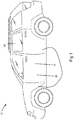
- FIG. 1 shows a door assembly 10 in accordance with an embodiment of the present invention, mounted to a body 11 of a vehicle 12.
- the door assembly 10 includes an outer panel 13, an inner panel 14 ( Figure 2 ), and a carrier/intrusion member assembly 16. The production of the door assembly 10 is facilitated directly as a result of the carrier/intrusion member assembly 16.
- a pair of hinges 23 (one of which is shown in Figure 5c ) are connected to the door panel structure 18 and pivotally mount the front end of the door panel structure (and the door assembly 10) to the vehicle body 11.
- a door latch 24 ( Figure 2 ) mounts to the rear end of the door panel structure 18 to permit the releasable closure of the door assembly 10 against the vehicle body 11.
- the hinges 23 and the door latch 24 acts as force transfer members through which forces in the door assembly 10 are transmitted to the vehicle 11. Such forces include, for example, side-impact forces from a vehicle colliding with the vehicle 12.
- At least one of the outer and inner panels 12 and 14 includes a latch reinforcement structure 25 that engages the door latch 24 and transmits forces in the door panel structure 18 thereto for transmission out of the door assembly 10 and into the vehicle body 11.
- the latch reinforcement structure 25 may simply be made up of a relatively thick metal plate that supports the door latch 24.
- at least one of the outer and inner panels 12 and 14 includes a hinge reinforcement structure 26 that engages the hinges 23 and transmits forces in the door panel structure 18 thereto for transmission out of the door assembly 10 and into the vehicle body 11.
- the hinge reinforcement structure 26 may simply be made up of one or more relatively thick metal plates that support the hinges 23.
- connection between the first and second ends 38 and 40 of the intrusion member 28 and the latch reinforcement structure 25 and the hinge reinforcement structure 26 may be by any suitable means, such as by welding, bonding, and/or by mechanical fasteners.
- the intrusion member 28 may connect to the carrier 27 by a snap-fit connection, such as is shown in Figure 7 .
- the intrusion member 28 may cooperate with the carrier 27 to form a hollow structure 44 that contains a carrier/intrusion member cavity 46.
- a hollow structure 44 that contains a carrier/intrusion member cavity 46.
- Figure 9 illustrates a door assembly 70 in accordance with another embodiment of the present invention, in which the intrusion member, shown at 100, has one first end 102 that is a latch end and is connected to a latch reinforcement structure and the latch, shown at 104, and two second ends 106a and 106b that are hinge ends that connect to the hinge reinforcement structures and the hinges shown at 108a and 108b respectively.
- FIG. 10 illustrates a method 200 of making the door assembly 10 in accordance with an embodiment of the present invention.
- the method 200 begins at 202.
- Step 204 includes providing a door panel structure, such as structure 18 and which includes an outer panel, such as outer panel 13 and an inner panel such as inner panel 14 connected together and together defining a door cavity, such as door cavity 20, between the inner and outer panels.
- Step 206 includes providing a carrier/intrusion member assembly, such as assembly 16, which includes a carrier such as carrier 27, an intrusion member (such as member 28) connected to the carrier, and a plurality of door hardware components (such as components 29 and 30) mounted to at least one of the carrier and the intrusion member.
- a carrier/intrusion member assembly such as assembly 16 which includes a carrier such as carrier 27, an intrusion member (such as member 28) connected to the carrier, and a plurality of door hardware components (such as components 29 and 30) mounted to at least one of the carrier and the intrusion member.
Abstract
Description
- The invention relates to vehicle door assemblies with intrusion members to protect vehicle occupants against side impacts, and with carriers for holding door hardware components.
- The automotive industry continuously seeks to better protect pedestrians from collisions with other vehicles. In particular, some attention has been paid to preventing occupant injury during side impacts, since there is relatively little structure in vehicle doors that is available to protect vehicle occupants, as compared to the safety structure present during frontal or rear-end collisions. In recent years, the use of side impact beams, also known as intrusion beams, has become more common. However, these beams in at least some instances have made more complicated the process of manufacturing vehicle door assemblies. In such cases, the intrusion beam extends across the opening that is used to mount the carrier to the inner door panel, and thus can interfere with the mounting of the carrier.
- There is therefore a need to provide a door assembly that provides good occupant protection while also being easy to manufacture.
- In an aspect, the invention is directed to a door assembly for a vehicle, that includes an outer panel, an inner panel and a carrier/intrusion member assembly. The outer panel and the inner panel are connected together to form a door panel structure, and together define a door cavity. The carrier/intrusion member assembly includes a carrier and an intrusion member connected to the carrier and mounted to the door panel structure. The carrier/intrusion member assembly further includes a plurality of door hardware components mounted to at least one of the carrier and the intrusion member. The hardware components extend into the door cavity.
- By providing the intrusion member and carrier together as an assembly, the assembly can be mounted to the door panel structure relatively easily because the installer does not need to maneuver the carrier and the door hardware components mounted thereto around a preexisting intrusion member that blocks an aperture into the door cavity, as is the case with some door assemblies of the prior art.
- In another aspect, the invention is directed to a carrier/intrusion member assembly that includes a carrier and an intrusion member connected to the carrier. The intrusion member further has a first end and a second end and includes a first mounting feature at the first end and a second mounting feature at the second end. The first and second mounting structures are positioned for use in mounting the intrusion member with a door panel structure. The carrier/intrusion member assembly further includes a plurality of window regulator components mounted to the carrier.
- In yet another aspect, the invention is directed to a carrier/intrusion member assembly that includes a carrier and an intrusion member connected to the carrier. The intrusion member and the carrier together define a carrier/intrusion member cavity. A plurality of door hardware components mounted to at least one of the carrier and the intrusion member.
- In yet another aspect, the invention is directed to a method of making a door assembly, comprising:
- a) providing a door panel structure including an outer panel and an inner panel connected together and together defining a door cavity between the inner and outer panels;
- b) providing a carrier/intrusion member assembly including a carrier, an intrusion member connected to the carrier, and a plurality of door hardware components mounted to at least one of the carrier and the intrusion member; and
- c) mounting the carrier/intrusion member assembly to the door panel structure at least in part by mounting the intrusion member to the door panel structure,
- The present invention will now be described by way of example only with reference to the attached drawings, in which:
-
Figure 1 is a perspective view of a vehicle with a door assembly in accordance with an embodiment of the present invention; -
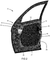
Figure 2 is a perspective view of the door assembly shown inFigure 1 alone; -
Figure 3 is a perspective view of a door panel structure that is part of the door assembly shown inFigure 2 ; -
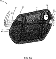
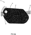
Figures 4a and4b are elevation views of a carrier/intrusion member assembly that is part of the door assembly shown inFigure 2 ; -
Figure 5a is a perspective view of a portion of the door assembly shown inFigure 2 ; -
Figure 5b is a sectional end view of the door assembly shown inFigure 2 ; -
Figure 5c is a magnified perspective view of a portion of the door assembly shown inFigure 2 ; -
Figure 6 is a side view of a variant of the carrier/intrusion member assembly shown inFigures 4a and4b ; -
Figure 7 is a side view of another variant of the carrier/intrusion member assembly shown inFigures 4a and4b ; -
Figure 8 is an end view of the carrier/intrusion member assembly shown inFigure 7 , showing the optional use of an energy absorption member; -
Figure 9 shows a transparent side view of a carrier/intrusion member assembly in accordance with another embodiment of the present invention; and - Figure 10 is a flow diagram illustrative of a method of making a door assembly in accordance with another embodiment of the present invention.
- Reference is made to
Figure 1 , which shows adoor assembly 10 in accordance with an embodiment of the present invention, mounted to abody 11 of avehicle 12. Thedoor assembly 10 includes anouter panel 13, an inner panel 14 (Figure 2 ), and a carrier/intrusion member assembly 16. The production of thedoor assembly 10 is facilitated directly as a result of the carrier/intrusion member assembly 16. - The
outer panel 13 forms at least part of the exterior surface of thedoor assembly 10. Theinner panel 14 provides a structural member for the mounting of one or more trim pieces that form an inner surface of thedoor assembly 10. Some of theinner panel 14 may itself also form part of the inner surface of thedoor assembly 10. The inner and outer panels are connected together and together form adoor panel structure 18 that contains a door cavity 20 (Figure 3 ). Anopening 22 in thedoor panel structure 18 provides access to thedoor cavity 20. - The outer and
inner panels inner panels outer panel 13 may be made from a suitable polymeric or composite material (e.g. fiberglass) and the inner panel may be made from a suitable metal. - A pair of hinges 23 (one of which is shown in
Figure 5c ) are connected to thedoor panel structure 18 and pivotally mount the front end of the door panel structure (and the door assembly 10) to thevehicle body 11. A door latch 24 (Figure 2 ) mounts to the rear end of thedoor panel structure 18 to permit the releasable closure of thedoor assembly 10 against thevehicle body 11. Thehinges 23 and thedoor latch 24 acts as force transfer members through which forces in thedoor assembly 10 are transmitted to thevehicle 11. Such forces include, for example, side-impact forces from a vehicle colliding with thevehicle 12. - Referring to
Figure 3 , at least one of the outer andinner panels latch reinforcement structure 25 that engages thedoor latch 24 and transmits forces in thedoor panel structure 18 thereto for transmission out of thedoor assembly 10 and into thevehicle body 11. Thelatch reinforcement structure 25 may simply be made up of a relatively thick metal plate that supports thedoor latch 24. Similarly, at least one of the outer andinner panels hinge reinforcement structure 26 that engages thehinges 23 and transmits forces in thedoor panel structure 18 thereto for transmission out of thedoor assembly 10 and into thevehicle body 11. Thehinge reinforcement structure 26 may simply be made up of one or more relatively thick metal plates that support thehinges 23. Thus, side impact forces incurred by thedoor assembly 10 can be transferred to thevehicle body 11 through thedoor latch 24 and thehinges 23. - The carrier/
intrusion member assembly 16 includes a carrier 27 (Figures 4a and4b ), anintrusion member 28 and a plurality of door hardware components 29 (Figure 5a ) including, for example, components from a window regulator shown at 30 (e.g. a motor driven cable drum (not shown), pulleys and cable guides (shown at 30a), lifter plates (not shown), window regulator rails (shown at 30b), and glass run channels (shown at 30c) for guiding the window (shown at 30d)). Other door hardware components 29 may include, for example, a speaker (not shown) for outputting sound from the vehicle's stereo system (not shown). The positions of the window regulator rails 30b are shown inFigure 3 also. - Referring to
Figure 5a , thecarrier 27 is a panel that holds a plurality of the aforementioned door hardware components 29 and is installing in position on thedoor panel structure 18 so that all of the attached door hardware components 29 are automatically in their necessary positions for operation. Thecarrier 27 may be made from a polymeric material or a metallic material. Thecarrier 27 mounts to thedoor panel structure 18 in such a way that thedoor hardware components 28 extend through theopening 22 in thedoor panel structure 18 into thedoor cavity 20. Referring toFigure 2 , thecarrier 27 has aperipheral edge 32 that sealingly engages theinner panel 14 to prevent the leakage of moisture therepast. In the embodiment shown, theperipheral edge 32 engages the inner face of theinner panel 14, (shown at 34 inFigure 5b ), however it will be understood that thecarrier 27 could alternatively mount entirely or partially to the outer face of the inner panel 14 (shown at 35 inFigure 5b ). - Referring to
Figure 2 , thecarrier 27 includes anaccess aperture 36 that permits access to thecomponents 28 in the door cavity after thecarrier 27 has been mounted to thedoor panel structure 18. After installation of components in thedoor cavity 20 is complete, theaccess aperture 36 may be closed by some suitable member to prevent moisture from leaking therepast. - The
intrusion member 28 is a member that strengthens thedoor assembly 10, and in particular increases the resistance of thedoor assembly 10 to intrusion into the vehicle cabin from a side-impact (e.g. from another vehicle colliding with the vehicle 12). Theintrusion member 28 may be made from any suitable material, such as a suitable metallic material. - The
intrusion member 28 has afirst end 38 and asecond end 40. In the embodiment shown, the first and second ends 38 and 40 of theintrusion member 28 extend past the peripheral edge of thecarrier 32, thereby facilitating the mounting of theintrusion member 28 directly to thedoor panel structure 18. This permits theintrusion member 28 to better assist thedoor assembly 10 in resisting deformation inwards from a side impact than if theintrusion member 28 were simply mounted to thecarrier 27 only and not directly to thedoor panel structure 18. - In a particularly advantageous embodiment, shown in
Figures 5a ,5b and5c , the first and second ends 38 and 40 of theintrusion member 28 have first and second mounting features 41 and 42 at the first and second ends 38 and 40 are connected to (and thus engage) thelatch reinforcement structure 25 and thehinge reinforcement structure 26 respectively. For this reason, thefirst end 38 of theintrusion member 28 may be referred to as ahinge end 38 in some embodiments, and thesecond end 40 may be referred to as a latch end in some embodiments. The first and second mounting features 41 and 42 may comprise one or more apertures for the pass-through of mechanical fasteners, side edge surfaces that are used for welding, a bottom surface that is used for bonding, or any other type of feature. As a result of being engaged with thelatch reinforcement structure 25 and thehinge reinforcement structure 26, theintrusion member 28 transmits side-impact forces incurred by thedoor assembly 10 to them and therefore out of thedoor assembly 10 into thevehicle body 11 through them. As a result, thevehicle body 11 itself assists in resisting deformation of thedoor assembly 10 from a side impact. - The connection between the first and second ends 38 and 40 of the
intrusion member 28 and thelatch reinforcement structure 25 and thehinge reinforcement structure 26 may be by any suitable means, such as by welding, bonding, and/or by mechanical fasteners. - From an ease-of-assembly point of view, however, by providing the carrier/intrusion member assembly 16 (i.e. by providing the
intrusion member 28 with the carrier 27), the installation of thecarrier 27 with all of the door hardware components 29 mounted thereto is facilitated as compared to some prior art door assemblies in which the carrier assembly with the door hardware components must be installed onto a door panel structure with an intrusion member already connected to the door panel structure. It can be difficult to maneuver the carrier assembly into place without interference occurring between a pre-installed intrusion member and the door hardware components (which can in some circumstances damage some of the door hardware components). - While the
carrier 27 itself mounts to thedoor panel structure 18 in the embodiments shown herein, it is possible in an alternative embodiment for thecarrier 27 to be sufficiently solidly connected to theintrusion member 28 and to not require direct mounting to thedoor panel structure 18. - The connection between the
carrier 27 and theintrusion member 28 may be by any suitable means. For example, in the embodiment shown inFigures 4a and4b thecarrier 27 is overmolded on theintrusion member 28. - By virtue of a rigid connection between the
carrier 27 and the intrusion member, as is provided by overmolding, theintrusion member 28 can add rigidity to thecarrier 27, so that thecarrier 27 can better act as a structural component of thedoor assembly 10 so as to help inhibit door sag and the like. - To assist in the transfer of forces between the
carrier 27 and theintrusion member 28, there may be provided a set of strengtheningribs 43 molded into thecarrier 27 that extend across theintrusion member 28. - In other embodiments, the
intrusion member 28 may connect to thecarrier 27 in other ways. For example, as shown inFigure 6 , thecarrier 27 may include preformed slots in the strengtheningribs 43, which permit the pass-through (e.g. from left to right), so as to loosely connect theintrusion member 28 to thecarrier 27. - In yet another embodiment, the
intrusion member 28 may connect to thecarrier 27 by a snap-fit connection, such as is shown inFigure 7 . - In some embodiments, such as the embodiment shown in
Figure 7 , theintrusion member 28 may cooperate with thecarrier 27 to form ahollow structure 44 that contains a carrier/intrusion member cavity 46. By forming a hollow structure, particularly when thecarrier 27 and theintrusion member 28 are connected fixedly enough to be able to transmit bending stresses to one another, the resistance to deformation of the hollow structure can be significantly higher than if thecarrier 27 andintrusion member 28 are connected with no hollow structure formed therebetween. - Optionally, as shown in
Figure 8 , the carrier/intrusion member cavity 46 may contain (and is preferably substantially filled with) anenergy absorption material 48. The energy absorption material may be any suitable type of material. For example, it may be aluminum foam, or alternatively magnesium foam or a polymeric foam. The term aluminum is meant to include both pure aluminum and aluminum alloys. Similarly, the term magnesium is intended to include both pure magnesium and magnesium alloys. - The
energy absorption material 48 may be provided initially in the form of a solid, preformed member. In embodiments wherein thecarrier 27 is preformed and then connected to theintrusion member 28, the solid preformed member made up ofenergy absorption material 48 can be inserted between thecarrier 27 and theintrusion member 28 as they are being joined together. Alternatively, theenergy absorption material 48 may be provided initially in the form of a flowable (e.g. molten) material that may be injected into thecavity 46 and which may be hardened, by any suitable means thereafter (e.g. by simply allowing it to cool). The energy absorption material acts to further dissipate energy from a side-impact thereby further reducing the degree of intrusion into the passenger compartment of thevehicle 12 that might occur from a side-impact. The passenger compartment is shown at 50 inFigure 1 . -
Figure 9 illustrates adoor assembly 70 in accordance with another embodiment of the present invention, in which the intrusion member, shown at 100, has onefirst end 102 that is a latch end and is connected to a latch reinforcement structure and the latch, shown at 104, and twosecond ends - Figure 10 illustrates a method 200 of making the
door assembly 10 in accordance with an embodiment of the present invention. The method 200 begins at 202. Step 204 includes providing a door panel structure, such asstructure 18 and which includes an outer panel, such asouter panel 13 and an inner panel such asinner panel 14 connected together and together defining a door cavity, such asdoor cavity 20, between the inner and outer panels. Step 206 includes providing a carrier/intrusion member assembly, such asassembly 16, which includes a carrier such ascarrier 27, an intrusion member (such as member 28) connected to the carrier, and a plurality of door hardware components (such as components 29 and 30) mounted to at least one of the carrier and the intrusion member. Step 208 includes mounting the carrier/intrusion member assembly to the door panel structure at least in part by mounting the intrusion member to the door panel structure. After step 208 the hardware components extend into the door cavity. The method 200 may further include step 210, which includes mounting the carrier to the door panel structure. Step 208 may optionally include step 212 which is mounting an end (i.e. a first end) of the intrusion member to the latch reinforcement structure. Alternatively or additionally, step 208 may optionally include step 214 which is mounting another end (i.e. a second end) of the intrusion member to the hinge reinforcement structure. Optionally, step 206 may include, providing the intrusion member, and overmolding the carrier over the intrusion member. The method ends at 216. - Optionally, the carrier and the intrusion member may together define a carrier/intrusion member cavity. The method 200 may further include step 218 which is providing an energy absorption material in the carrier/intrusion member cavity, which may entail providing a flowable material; injecting the flowable material into the carrier/intrusion member cavity; and hardening the flowable material to form the energy absorption material.
- While the above description constitutes a plurality of embodiments of the present invention, it will be appreciated that the present invention is susceptible to further modification and change without departing from the fair meaning of the accompanying claims.
Claims (13)
- A carrier/intrusion member assembly (16) for mounting to a door panel structure (18) in a door assembly (10) for a vehicle, comprising:a carrier (27);an intrusion member (28) connected to the carrier (27), wherein the intrusion member (28) further has a first end (38) and a second end (40) and includes a first mounting feature (41) at the first end (38) and a second mounting feature (42) at the second end (40), wherein the first and second mounting structures (41, 41) are mateable with associated portions of the door panel structure (18), wherein the carrier (27) is overmoulded on the intrusion member (28); anda plurality of door hardware components (29) extending into the door cavity, wherein the plurality of door hardware components (29) is mounted to at least one of the carrier (27) and the intrusion member (28).
- The carrier/intrusion member assembly (16) as claimed in claim 1, wherein the carrier (27) is mounted to the door panel structure (18).
- The carrier/intrusion member assembly (16) as claimed in claim 1 or 2, wherein the carrier (27) has a peripheral edge (32) and sealingly engages the inner panel (14) along the peripheral edge (32).
- The carrier/intrusion member assembly (16) as claimed in any one of claims 1 to 3, wherein the carrier (27) has a peripheral edge (32) and wherein the intrusion member (28) has at least one end that extends past the peripheral edge (32) of the carrier (27).
- The carrier/intrusion member assembly (16) as claimed in any one of claims 1 to 4, wherein the carrier (27) is made from a polymeric material and the intrusion member (28) is made from a metallic material.
- The carrier/intrusion member assembly (16) as claimed in any one of claims 1 to 5, wherein at least one of the inner and outer panels (14, 13) includes a latch reinforcement structure that is connected with a door latch and is configured to transfer forces from the door panel structure (18) to a body of the vehicle through the door latch, wherein a latch end of the intrusion member (28) connects to the latch reinforcement structure.
- The carrier/intrusion member assembly (16) as claimed in any one of claims 1 to 6, wherein at least one of the inner and outer panels includes a hinge reinforcement structure that is at least indirectly connected with at least one door hinge and is configured to transfer forces from the door panel structure (18) to a body of the vehicle through the at least one door hinge, wherein a hinge end of the intrusion member (28) connects to the hinge reinforcement structure.
- The carrier/intrusion member assembly (16) as claimed in claim 7, wherein the latch end of the intrusion member (28) connects to the latch reinforcement structure inside the door cavity, and wherein the intrusion member (28) has a second end that connects to the door panel structure (18) outside the door cavity.
- The carrier/intrusion member assembly (16) as claimed in any one of claims 1 to 8, wherein the plurality of hardware components (29) comprise a plurality of window regulator components.
- The carrier/intrusion member assembly (16) as claimed in any one of claims 1 to 9, wherein the carrier (27) and the intrusion member (28) together define a carrier/intrusion member cavity.
- The carrier/intrusion member assembly (16) as claimed in any one of claims 1 to 10, wherein the carrier/intrusion member cavity contains an energy absorption material.
- A door assembly (10) for a motor vehicle, comprising:an outer panel (13);an inner panel (14) connected to the outer panel, wherein the inner and outer panels (14, 13) together form a door panel structure (18) defining a door cavity (20) between the inner and outer panels;a carrier/intrusion member assembly (16) including a carrier (27) and an intrusion member (28), the intrusion member (28) being connected to the carrier (27) and separate from the door panel structure (18), the intrusion member (28) extending across the door cavity and mounted to the door panel structure (18), wherein the carrier (27) is made from a polymeric material and the intrusion member (28) is made from a metallic material; anda plurality of door hardware components (29) extending into the door cavity, wherein the plurality of door hardware components (29) is mounted to at least one of the carrier (27) and the intrusion member (28).
- A door assembly (10) for a motor vehicle, comprising:an outer panel (13) ;an inner panel (14) connected to the outer panel, wherein the inner and outer panels (14, 13) together form a door panel structure (18) defining a door cavity (20) between the inner and outer panels; anda carrier/intrusion member assembly (16) according to any one of claims 1 to 11 mounted to the door panel structure (18).
Applications Claiming Priority (3)
| Application Number | Priority Date | Filing Date | Title |
|---|---|---|---|
| US201161479908P | 2011-04-28 | 2011-04-28 | |
| PCT/CA2012/050276 WO2012145849A1 (en) | 2011-04-28 | 2012-04-30 | Door assembly with carrier with intrusion member |
| EP12776793.7A EP2701965B1 (en) | 2011-04-28 | 2012-04-30 | Door assembly with carrier with intrusion member |
Related Parent Applications (1)
| Application Number | Title | Priority Date | Filing Date |
|---|---|---|---|
| EP12776793.7A Division EP2701965B1 (en) | 2011-04-28 | 2012-04-30 | Door assembly with carrier with intrusion member |
Publications (1)
| Publication Number | Publication Date |
|---|---|
| EP3517411A1 true EP3517411A1 (en) | 2019-07-31 |
Family
ID=47071526
Family Applications (2)
| Application Number | Title | Priority Date | Filing Date |
|---|---|---|---|
| EP18189084.9A Pending EP3517411A1 (en) | 2011-04-28 | 2012-04-30 | Door assembly with carrier with intrusion member |
| EP12776793.7A Active EP2701965B1 (en) | 2011-04-28 | 2012-04-30 | Door assembly with carrier with intrusion member |
Family Applications After (1)
| Application Number | Title | Priority Date | Filing Date |
|---|---|---|---|
| EP12776793.7A Active EP2701965B1 (en) | 2011-04-28 | 2012-04-30 | Door assembly with carrier with intrusion member |
Country Status (4)
| Country | Link |
|---|---|
| US (1) | US9126470B2 (en) |
| EP (2) | EP3517411A1 (en) |
| CN (2) | CN108909415B (en) |
| WO (1) | WO2012145849A1 (en) |
Families Citing this family (8)
| Publication number | Priority date | Publication date | Assignee | Title |
|---|---|---|---|---|
| CN108909415B (en) * | 2011-04-28 | 2021-10-15 | 马格纳·克劳祖雷斯有限公司 | Door assembly with carrier and intrusion prevention member |
| CA2992296A1 (en) * | 2015-07-23 | 2017-01-26 | Magna International Inc. | Vehicle door assembly |
| FR3039806B1 (en) * | 2015-08-05 | 2017-08-25 | Peugeot Citroen Automobiles Sa | IMPROVED DOOR PANEL PROTECTION |
| KR20180068108A (en) * | 2016-12-13 | 2018-06-21 | 현대자동차주식회사 | Door structure for vehicle |
| DE102018115442A1 (en) * | 2017-06-30 | 2019-01-10 | Magna Closures Inc. | Door arrangement with collapsible support and water shield |
| US10350973B2 (en) * | 2017-07-17 | 2019-07-16 | Ford Global Technologies, Llc | Bracket to connect interior door trim grab handle with integrated window regulator carrier |
| US11124051B2 (en) * | 2018-06-29 | 2021-09-21 | Magna Closures Inc. | Hybrid door module |
| US11446988B2 (en) | 2018-12-04 | 2022-09-20 | Magna Closures Inc. | Hybrid door module |
Citations (3)
| Publication number | Priority date | Publication date | Assignee | Title |
|---|---|---|---|---|
| DE19519509A1 (en) * | 1994-05-31 | 1995-12-07 | Linde & Wiemann Gmbh Kg | Vehicle door with frame and side impact protector |
| EP1275540A2 (en) * | 2001-07-10 | 2003-01-15 | Bayerische Motoren Werke Aktiengesellschaft | Vehicle door with re-enforced carrier panel and integrated belt-line |
| WO2007111878A2 (en) * | 2006-03-23 | 2007-10-04 | Exxonmobil Chemical Patents Inc. | Door assembly with integrated window sealing system |
Family Cites Families (43)
| Publication number | Priority date | Publication date | Assignee | Title |
|---|---|---|---|---|
| US3868796A (en) | 1973-04-04 | 1975-03-04 | Ford Motor Co | Side door intrusion protection |
| DE3217640A1 (en) * | 1982-03-12 | 1983-11-17 | Brose Fahrzeugteile GmbH & Co KG, 8630 Coburg | VEHICLE DOOR |
| US4800638A (en) * | 1987-08-25 | 1989-01-31 | The Budd Company | Method of mounting an outer skin to an inner panel of a vehicle door |
| US5306066A (en) * | 1992-10-15 | 1994-04-26 | Ford Motor Company | Energy absorbing vehicle doors |
| US5536060A (en) * | 1995-02-17 | 1996-07-16 | General Motors Corporation | Reinforced vehicle door |
| US6196619B1 (en) * | 1995-12-22 | 2001-03-06 | Joalto Design, Inc. | Vehicle closure panel having an intrusion beam as primary structure |
| US5647631A (en) * | 1996-09-05 | 1997-07-15 | Kia Motors Corporation | Vehicle door |
| US6164716A (en) * | 1998-12-18 | 2000-12-26 | Daimlerchrysler Corporation | Energy dissipating body panel assembly |
| AT4670U1 (en) * | 2000-06-28 | 2001-10-25 | Steyr Daimler Puch Ag | MOTOR VEHICLE DOOR |
| DE10042409A1 (en) * | 2000-08-30 | 2002-03-28 | Porsche Ag | Structure for a motor vehicle |
| DE10060632A1 (en) * | 2000-12-06 | 2002-07-04 | Gerald Fellner | vehicle door |
| WO2003037669A1 (en) * | 2001-10-31 | 2003-05-08 | Lear Corporation | Integrated door module |
| JP3701611B2 (en) * | 2002-01-16 | 2005-10-05 | 本田技研工業株式会社 | Automotive door |
| JP2003205745A (en) * | 2002-01-16 | 2003-07-22 | Honda Motor Co Ltd | Door for automobile |
| US6779830B2 (en) | 2002-04-09 | 2004-08-24 | Ford Global Technologies, Llc | Anti-intrusion beam for a vehicle door assembly |
| SE522423C2 (en) * | 2002-08-08 | 2004-02-10 | Ssab Hardtech Ab | Vehicle door and ways to manufacture such |
| JP3938000B2 (en) | 2002-10-17 | 2007-06-27 | マツダ株式会社 | Shock absorbing structure for vehicle side door |
| JP2004175169A (en) * | 2002-11-26 | 2004-06-24 | Mitsubishi Motors Corp | Vehicle door |
| US7040688B2 (en) * | 2003-04-29 | 2006-05-09 | General Motors Corporation | Vehicle door |
| US6805397B1 (en) * | 2003-04-30 | 2004-10-19 | General Motors Corporation | Vehicle door |
| JP2007508186A (en) * | 2003-10-14 | 2007-04-05 | インティアー オートモーティヴ クロージャーズ インコーポレイテッド | Car door structure |
| WO2005058625A1 (en) * | 2003-12-17 | 2005-06-30 | Sumitomo Metal Industries Ltd. | Metal tube for reinforcing vehicle body and member for reinforcing vehicle body using the same |
| DE112005000407B4 (en) * | 2004-02-27 | 2010-08-05 | General Motors Corp. (N.D.Ges.D. Staates Delaware), Detroit | Closing assembly of mixed metals and methods |
| US7014249B2 (en) | 2004-08-11 | 2006-03-21 | General Motors Corporation | Impact beam-integrated pelvic pusher |
| JP4573099B2 (en) * | 2004-09-27 | 2010-11-04 | マツダ株式会社 | Car door structure |
| US8419111B2 (en) * | 2005-03-02 | 2013-04-16 | Nippon Steel & Sumitomo Metal Corporation | Vehicle body reinforcing member |
| JP4836570B2 (en) * | 2005-12-26 | 2011-12-14 | ダイキョーニシカワ株式会社 | Resin panel and automobile door |
| US20070278819A1 (en) * | 2006-04-28 | 2007-12-06 | Seksaria Dinesh C | Light weight modular hinged door |
| CN101448662A (en) * | 2006-05-11 | 2009-06-03 | 马格纳·克劳祖雷斯有限公司 | Inner panel for a door assembly having an integrated intrusion beam |
| CN101122206B (en) * | 2006-08-09 | 2011-12-21 | 上海华普汽车有限公司 | Passenger car door |
| JP4305484B2 (en) * | 2006-09-26 | 2009-07-29 | 日産自動車株式会社 | Door panel structure and door panel manufacturing method |
| US7774925B2 (en) * | 2006-10-19 | 2010-08-17 | Gm Global Technology Operations, Inc. | Method for in-situ foaming of metal foam in hollow structure |
| JP5035218B2 (en) * | 2007-12-27 | 2012-09-26 | 豊田合成株式会社 | Automotive door |
| US8033592B2 (en) * | 2008-08-27 | 2011-10-11 | GM Global Technology Operations LLC | Door assembly and method for a vehicle |
| DE102008050265B4 (en) * | 2008-10-07 | 2015-04-09 | Küster Holding GmbH | Aggregate carrier with reinforcing element |
| BRPI1008331A2 (en) * | 2009-02-11 | 2020-08-25 | Honda Motor Co., Ltd. | vehicle door structure |
| US7819462B1 (en) | 2009-04-21 | 2010-10-26 | Gm Global Technology Operations, Inc. | Anti-intrusion beam for vehicle door assembly |
| JP4876142B2 (en) * | 2009-05-27 | 2012-02-15 | 本田技研工業株式会社 | Body side structure |
| EP2512849B1 (en) * | 2009-12-17 | 2017-04-26 | Volvo Lastvagnar AB | Vehicle door reinforcement structure |
| US8763708B2 (en) * | 2010-10-12 | 2014-07-01 | Weatherford/Lamb, Inc. | Wellhead rotating breech lock and method |
| US8371639B2 (en) * | 2010-10-14 | 2013-02-12 | GM Global Technology Operations LLC | Snap fit bracket for side door impact beam |
| CN108909415B (en) * | 2011-04-28 | 2021-10-15 | 马格纳·克劳祖雷斯有限公司 | Door assembly with carrier and intrusion prevention member |
| KR101327121B1 (en) * | 2011-12-01 | 2013-11-07 | 기아자동차주식회사 | Supporting Structure Of Door Impact Beam For Vehicle |
-
2012
- 2012-04-30 CN CN201810630509.2A patent/CN108909415B/en active Active
- 2012-04-30 CN CN201280029141.5A patent/CN103619692B/en active Active
- 2012-04-30 EP EP18189084.9A patent/EP3517411A1/en active Pending
- 2012-04-30 EP EP12776793.7A patent/EP2701965B1/en active Active
- 2012-04-30 WO PCT/CA2012/050276 patent/WO2012145849A1/en active Application Filing
- 2012-04-30 US US14/114,293 patent/US9126470B2/en active Active
Patent Citations (3)
| Publication number | Priority date | Publication date | Assignee | Title |
|---|---|---|---|---|
| DE19519509A1 (en) * | 1994-05-31 | 1995-12-07 | Linde & Wiemann Gmbh Kg | Vehicle door with frame and side impact protector |
| EP1275540A2 (en) * | 2001-07-10 | 2003-01-15 | Bayerische Motoren Werke Aktiengesellschaft | Vehicle door with re-enforced carrier panel and integrated belt-line |
| WO2007111878A2 (en) * | 2006-03-23 | 2007-10-04 | Exxonmobil Chemical Patents Inc. | Door assembly with integrated window sealing system |
Also Published As
| Publication number | Publication date |
|---|---|
| EP2701965B1 (en) | 2018-08-22 |
| CN103619692A (en) | 2014-03-05 |
| CN103619692B (en) | 2018-07-17 |
| CN108909415B (en) | 2021-10-15 |
| EP2701965A4 (en) | 2014-09-03 |
| EP2701965A1 (en) | 2014-03-05 |
| US20140125087A1 (en) | 2014-05-08 |
| WO2012145849A1 (en) | 2012-11-01 |
| US9126470B2 (en) | 2015-09-08 |
| CN108909415A (en) | 2018-11-30 |
Similar Documents
| Publication | Publication Date | Title |
|---|---|---|
| US9126470B2 (en) | Door assembly with carrier with intrusion member | |
| US8668250B2 (en) | Side structure of a vehicle | |
| EP3056366B1 (en) | Vehicle exterior design member and vehicle back door | |
| US10676975B2 (en) | Door assembly with collapsible carrier | |
| US20070278819A1 (en) | Light weight modular hinged door | |
| US20140319877A1 (en) | Side panel structure for vehicle | |
| JP2010173562A (en) | Side body structure for vehicle | |
| CN108068587B (en) | Impact beam structure for carbon fiber reinforced plastic door of vehicle | |
| KR101637303B1 (en) | Door structure for motor vehicle | |
| EP3632776A1 (en) | Vehicle body and method of forming the same | |
| US11148511B2 (en) | Vehicle door assembly | |
| US20200001691A1 (en) | Hybrid door module | |
| US7380865B2 (en) | Vehicle door and method for the production thereof | |
| US20080238136A1 (en) | Motor Vehicle Door | |
| US11938796B2 (en) | Vehicle with exoskeleton | |
| EP2109547A1 (en) | Vehicle door | |
| US20080258495A1 (en) | Motor Vehicle Door | |
| EP1960253B1 (en) | Hatch frame for vehicle | |
| JP5030053B2 (en) | Vehicle door structure | |
| KR0162153B1 (en) | A reinforcing structure of a center pillar | |
| KR20230139221A (en) | Vehicle front pillar reinforcement system |
Legal Events
| Date | Code | Title | Description |
|---|---|---|---|
| PUAI | Public reference made under article 153(3) epc to a published international application that has entered the european phase |
Free format text: ORIGINAL CODE: 0009012 |
|
| STAA | Information on the status of an ep patent application or granted ep patent |
Free format text: STATUS: REQUEST FOR EXAMINATION WAS MADE |
|
| 17P | Request for examination filed |
Effective date: 20180815 |
|
| AC | Divisional application: reference to earlier application |
Ref document number: 2701965 Country of ref document: EP Kind code of ref document: P |
|
| AK | Designated contracting states |
Kind code of ref document: A1 Designated state(s): AL AT BE BG CH CY CZ DE DK EE ES FI FR GB GR HR HU IE IS IT LI LT LU LV MC MK MT NL NO PL PT RO RS SE SI SK SM TR |
|
| STAA | Information on the status of an ep patent application or granted ep patent |
Free format text: STATUS: EXAMINATION IS IN PROGRESS |
|
| STAA | Information on the status of an ep patent application or granted ep patent |
Free format text: STATUS: EXAMINATION IS IN PROGRESS |
|
| 17Q | First examination report despatched |
Effective date: 20201215 |
|
| GRAP | Despatch of communication of intention to grant a patent |
Free format text: ORIGINAL CODE: EPIDOSNIGR1 |
|
| STAA | Information on the status of an ep patent application or granted ep patent |
Free format text: STATUS: GRANT OF PATENT IS INTENDED |
|
| INTG | Intention to grant announced |
Effective date: 20210806 |