EP3517226A2 - Cleaning device - Google Patents
Cleaning device Download PDFInfo
- Publication number
- EP3517226A2 EP3517226A2 EP19153909.7A EP19153909A EP3517226A2 EP 3517226 A2 EP3517226 A2 EP 3517226A2 EP 19153909 A EP19153909 A EP 19153909A EP 3517226 A2 EP3517226 A2 EP 3517226A2
- Authority
- EP
- European Patent Office
- Prior art keywords
- cleaning
- spray arm
- cleaning device
- cleaning head
- hollow shaft
- Prior art date
- Legal status (The legal status is an assumption and is not a legal conclusion. Google has not performed a legal analysis and makes no representation as to the accuracy of the status listed.)
- Granted
Links
- 238000004140 cleaning Methods 0.000 title claims abstract description 528
- 239000007921 spray Substances 0.000 claims abstract description 163
- 239000012530 fluid Substances 0.000 claims abstract description 89
- 239000007788 liquid Substances 0.000 claims abstract description 76
- 230000005540 biological transmission Effects 0.000 claims description 23
- 230000033001 locomotion Effects 0.000 description 30
- 239000002245 particle Substances 0.000 description 8
- 238000011109 contamination Methods 0.000 description 6
- 238000007654 immersion Methods 0.000 description 5
- 238000007789 sealing Methods 0.000 description 5
- 238000010276 construction Methods 0.000 description 4
- 238000000034 method Methods 0.000 description 4
- 230000035515 penetration Effects 0.000 description 4
- 230000001105 regulatory effect Effects 0.000 description 4
- 230000003044 adaptive effect Effects 0.000 description 3
- 230000000712 assembly Effects 0.000 description 3
- 238000000429 assembly Methods 0.000 description 3
- 238000005507 spraying Methods 0.000 description 3
- 238000005299 abrasion Methods 0.000 description 2
- 230000006978 adaptation Effects 0.000 description 2
- 230000008859 change Effects 0.000 description 2
- 239000012459 cleaning agent Substances 0.000 description 2
- 239000000356 contaminant Substances 0.000 description 2
- 238000011010 flushing procedure Methods 0.000 description 2
- 238000012544 monitoring process Methods 0.000 description 2
- 239000002253 acid Substances 0.000 description 1
- 230000000903 blocking effect Effects 0.000 description 1
- 230000008878 coupling Effects 0.000 description 1
- 238000010168 coupling process Methods 0.000 description 1
- 238000005859 coupling reaction Methods 0.000 description 1
- 230000001419 dependent effect Effects 0.000 description 1
- 239000003599 detergent Substances 0.000 description 1
- 238000005538 encapsulation Methods 0.000 description 1
- 239000006260 foam Substances 0.000 description 1
- 238000009434 installation Methods 0.000 description 1
- 230000000149 penetrating effect Effects 0.000 description 1
- 230000008569 process Effects 0.000 description 1
- 230000000284 resting effect Effects 0.000 description 1
- HEMHJVSKTPXQMS-UHFFFAOYSA-M sodium hydroxide Substances [OH-].[Na+] HEMHJVSKTPXQMS-UHFFFAOYSA-M 0.000 description 1
- 230000007704 transition Effects 0.000 description 1
- 229910021642 ultra pure water Inorganic materials 0.000 description 1
- 239000012498 ultrapure water Substances 0.000 description 1
Images


Classifications
-
- B—PERFORMING OPERATIONS; TRANSPORTING
- B05—SPRAYING OR ATOMISING IN GENERAL; APPLYING FLUENT MATERIALS TO SURFACES, IN GENERAL
- B05B—SPRAYING APPARATUS; ATOMISING APPARATUS; NOZZLES
- B05B15/00—Details of spraying plant or spraying apparatus not otherwise provided for; Accessories
- B05B15/50—Arrangements for cleaning; Arrangements for preventing deposits, drying-out or blockage; Arrangements for detecting improper discharge caused by the presence of foreign matter
- B05B15/55—Arrangements for cleaning; Arrangements for preventing deposits, drying-out or blockage; Arrangements for detecting improper discharge caused by the presence of foreign matter using cleaning fluids
- B05B15/555—Arrangements for cleaning; Arrangements for preventing deposits, drying-out or blockage; Arrangements for detecting improper discharge caused by the presence of foreign matter using cleaning fluids discharged by cleaning nozzles
-
- B—PERFORMING OPERATIONS; TRANSPORTING
- B05—SPRAYING OR ATOMISING IN GENERAL; APPLYING FLUENT MATERIALS TO SURFACES, IN GENERAL
- B05B—SPRAYING APPARATUS; ATOMISING APPARATUS; NOZZLES
- B05B1/00—Nozzles, spray heads or other outlets, with or without auxiliary devices such as valves, heating means
- B05B1/26—Nozzles, spray heads or other outlets, with or without auxiliary devices such as valves, heating means with means for mechanically breaking-up or deflecting the jet after discharge, e.g. with fixed deflectors; Breaking-up the discharged liquid or other fluent material by impinging jets
- B05B1/262—Nozzles, spray heads or other outlets, with or without auxiliary devices such as valves, heating means with means for mechanically breaking-up or deflecting the jet after discharge, e.g. with fixed deflectors; Breaking-up the discharged liquid or other fluent material by impinging jets with fixed deflectors
- B05B1/265—Nozzles, spray heads or other outlets, with or without auxiliary devices such as valves, heating means with means for mechanically breaking-up or deflecting the jet after discharge, e.g. with fixed deflectors; Breaking-up the discharged liquid or other fluent material by impinging jets with fixed deflectors the liquid or other fluent material being symmetrically deflected about the axis of the nozzle
-
- B—PERFORMING OPERATIONS; TRANSPORTING
- B05—SPRAYING OR ATOMISING IN GENERAL; APPLYING FLUENT MATERIALS TO SURFACES, IN GENERAL
- B05B—SPRAYING APPARATUS; ATOMISING APPARATUS; NOZZLES
- B05B12/00—Arrangements for controlling delivery; Arrangements for controlling the spray area
- B05B12/08—Arrangements for controlling delivery; Arrangements for controlling the spray area responsive to condition of liquid or other fluent material to be discharged, of ambient medium or of target ; responsive to condition of spray devices or of supply means, e.g. pipes, pumps or their drive means
- B05B12/082—Arrangements for controlling delivery; Arrangements for controlling the spray area responsive to condition of liquid or other fluent material to be discharged, of ambient medium or of target ; responsive to condition of spray devices or of supply means, e.g. pipes, pumps or their drive means responsive to a condition of the discharged jet or spray, e.g. to jet shape, spray pattern or droplet size
-
- B—PERFORMING OPERATIONS; TRANSPORTING
- B05—SPRAYING OR ATOMISING IN GENERAL; APPLYING FLUENT MATERIALS TO SURFACES, IN GENERAL
- B05B—SPRAYING APPARATUS; ATOMISING APPARATUS; NOZZLES
- B05B12/00—Arrangements for controlling delivery; Arrangements for controlling the spray area
- B05B12/14—Arrangements for controlling delivery; Arrangements for controlling the spray area for supplying a selected one of a plurality of liquids or other fluent materials or several in selected proportions to a spray apparatus, e.g. to a single spray outlet
- B05B12/1472—Arrangements for controlling delivery; Arrangements for controlling the spray area for supplying a selected one of a plurality of liquids or other fluent materials or several in selected proportions to a spray apparatus, e.g. to a single spray outlet separate supply lines supplying different materials to separate outlets of the spraying apparatus
-
- B—PERFORMING OPERATIONS; TRANSPORTING
- B05—SPRAYING OR ATOMISING IN GENERAL; APPLYING FLUENT MATERIALS TO SURFACES, IN GENERAL
- B05B—SPRAYING APPARATUS; ATOMISING APPARATUS; NOZZLES
- B05B12/00—Arrangements for controlling delivery; Arrangements for controlling the spray area
- B05B12/16—Arrangements for controlling delivery; Arrangements for controlling the spray area for controlling the spray area
-
- B—PERFORMING OPERATIONS; TRANSPORTING
- B05—SPRAYING OR ATOMISING IN GENERAL; APPLYING FLUENT MATERIALS TO SURFACES, IN GENERAL
- B05B—SPRAYING APPARATUS; ATOMISING APPARATUS; NOZZLES
- B05B13/00—Machines or plants for applying liquids or other fluent materials to surfaces of objects or other work by spraying, not covered by groups B05B1/00 - B05B11/00
- B05B13/06—Machines or plants for applying liquids or other fluent materials to surfaces of objects or other work by spraying, not covered by groups B05B1/00 - B05B11/00 specially designed for treating the inside of hollow bodies
- B05B13/0627—Arrangements of nozzles or spray heads specially adapted for treating the inside of hollow bodies
- B05B13/0636—Arrangements of nozzles or spray heads specially adapted for treating the inside of hollow bodies by means of rotatable spray heads or nozzles
-
- B—PERFORMING OPERATIONS; TRANSPORTING
- B05—SPRAYING OR ATOMISING IN GENERAL; APPLYING FLUENT MATERIALS TO SURFACES, IN GENERAL
- B05B—SPRAYING APPARATUS; ATOMISING APPARATUS; NOZZLES
- B05B15/00—Details of spraying plant or spraying apparatus not otherwise provided for; Accessories
- B05B15/60—Arrangements for mounting, supporting or holding spraying apparatus
- B05B15/65—Mounting arrangements for fluid connection of the spraying apparatus or its outlets to flow conduits
- B05B15/656—Mounting arrangements for fluid connection of the spraying apparatus or its outlets to flow conduits whereby the flow conduit length is changeable
-
- B—PERFORMING OPERATIONS; TRANSPORTING
- B05—SPRAYING OR ATOMISING IN GENERAL; APPLYING FLUENT MATERIALS TO SURFACES, IN GENERAL
- B05B—SPRAYING APPARATUS; ATOMISING APPARATUS; NOZZLES
- B05B3/00—Spraying or sprinkling apparatus with moving outlet elements or moving deflecting elements
- B05B3/02—Spraying or sprinkling apparatus with moving outlet elements or moving deflecting elements with rotating elements
- B05B3/025—Rotational joints
- B05B3/026—Rotational joints the fluid passing axially from one joint element to another
-
- B—PERFORMING OPERATIONS; TRANSPORTING
- B05—SPRAYING OR ATOMISING IN GENERAL; APPLYING FLUENT MATERIALS TO SURFACES, IN GENERAL
- B05B—SPRAYING APPARATUS; ATOMISING APPARATUS; NOZZLES
- B05B3/00—Spraying or sprinkling apparatus with moving outlet elements or moving deflecting elements
- B05B3/02—Spraying or sprinkling apparatus with moving outlet elements or moving deflecting elements with rotating elements
- B05B3/028—Spraying or sprinkling apparatus with moving outlet elements or moving deflecting elements with rotating elements the rotation being orbital
-
- B—PERFORMING OPERATIONS; TRANSPORTING
- B08—CLEANING
- B08B—CLEANING IN GENERAL; PREVENTION OF FOULING IN GENERAL
- B08B9/00—Cleaning hollow articles by methods or apparatus specially adapted thereto
- B08B9/08—Cleaning containers, e.g. tanks
- B08B9/093—Cleaning containers, e.g. tanks by the force of jets or sprays
- B08B9/0936—Cleaning containers, e.g. tanks by the force of jets or sprays using rotating jets
-
- B—PERFORMING OPERATIONS; TRANSPORTING
- B05—SPRAYING OR ATOMISING IN GENERAL; APPLYING FLUENT MATERIALS TO SURFACES, IN GENERAL
- B05B—SPRAYING APPARATUS; ATOMISING APPARATUS; NOZZLES
- B05B1/00—Nozzles, spray heads or other outlets, with or without auxiliary devices such as valves, heating means
- B05B1/14—Nozzles, spray heads or other outlets, with or without auxiliary devices such as valves, heating means with multiple outlet openings; with strainers in or outside the outlet opening
-
- B—PERFORMING OPERATIONS; TRANSPORTING
- B05—SPRAYING OR ATOMISING IN GENERAL; APPLYING FLUENT MATERIALS TO SURFACES, IN GENERAL
- B05B—SPRAYING APPARATUS; ATOMISING APPARATUS; NOZZLES
- B05B13/00—Machines or plants for applying liquids or other fluent materials to surfaces of objects or other work by spraying, not covered by groups B05B1/00 - B05B11/00
- B05B13/02—Means for supporting work; Arrangement or mounting of spray heads; Adaptation or arrangement of means for feeding work
- B05B13/04—Means for supporting work; Arrangement or mounting of spray heads; Adaptation or arrangement of means for feeding work the spray heads being moved during spraying operation
- B05B13/0421—Means for supporting work; Arrangement or mounting of spray heads; Adaptation or arrangement of means for feeding work the spray heads being moved during spraying operation with rotating spray heads
-
- B—PERFORMING OPERATIONS; TRANSPORTING
- B05—SPRAYING OR ATOMISING IN GENERAL; APPLYING FLUENT MATERIALS TO SURFACES, IN GENERAL
- B05B—SPRAYING APPARATUS; ATOMISING APPARATUS; NOZZLES
- B05B15/00—Details of spraying plant or spraying apparatus not otherwise provided for; Accessories
- B05B15/60—Arrangements for mounting, supporting or holding spraying apparatus
- B05B15/68—Arrangements for adjusting the position of spray heads
Definitions
- the invention relates to a cleaning device according to the features of the preamble of claim 1.
- a nozzle carrier of a cleaning head On the drive shaft, a nozzle carrier of a cleaning head is arranged rotationally fixed.
- a nozzle unit is rotatably mounted with at least one nozzle.
- the nozzle carrier is rotatably mounted on a bearing tube.
- the bearing tube is coupled by gear means with the nozzle unit such that a caused by the drive shaft relative rotational movement of the nozzle carrier relative to the bearing tube causes a rotational movement of the nozzle unit with respect to the nozzle carrier.
- the object of the invention is to specify a cleaning device which is improved over the prior art.
- a cleaning device for cleaning with a cleaning liquid, in particular for cleaning, in particular internal cleaning, of hollow bodies comprises a tubular section, at least one cleaning head rotatable about a first axis of rotation on a cleaning head end region of the tubular section, a spray arm which is at least substantially perpendicular to the first Rotary axis aligned second axis of rotation is rotatably mounted on the cleaning head, a drive device for driving the cleaning head and the spray arm at a cleaning head end region opposite drive end of the tubular portion and a cleaning liquid line for the cleaning liquid, which passes through the tubular portion.
- the cleaning fluid line also passes through the cleaning head and the spray arm and opens into at least one outlet opening, wherein the cleaning fluid line is designed to be liquid-tight with respect to a cleaning device interior.
- all cleaning device components are arranged outside the cleaning fluid line.
- the cleaning fluid line is thus formed as a relative to the cleaning device interior completely closed line, for example tubular, tubular or channel-shaped, for example as a cleaning fluid tube, cleaning fluid tube or cleaning fluid channel. It thus has its own, within the cleaning device completely closed pipe wall.
- This conduit wall encloses a line interior, which is provided exclusively for the flow through, in particular for the passage of the cleaning liquid.
- no other cleaning device component is arranged, in particular no drive component, in particular no drive shaft, no transmission component, no transmission, no bearing component and no bearing, ie in particular no required for rotating the cleaning head and / or the spray arm and in particular for this self-moving component.
- the solution according to the invention achieves, at least substantially, a constant flow cross-section of the cleaning fluid line, as a result of which pressure losses are reduced.
- a swirling of the cleaning liquid and a resulting flow disturbance is arranged in the cleaning liquid line and in particular moving therein Cleaning device components avoided because in the inventive solution no such cleaning device components are present in the cleaning fluid line.
- the cleaning fluid line runs completely through the tubular section, ie from the drive end area to the cleaning head end area.
- it enters the drive end portion in the axial direction of the tubular portion, and the end portion of the cleaning head in the axial direction of the tubular portion thereof.
- a lateral, ie radially to the tubular portion extending entry of the cleaning liquid line in the tubular portion and an associated crossing in the tubular portion of rotating components or entry into these rotating components, for example, associated with elaborate sealing measures avoided.
- the tubular section, the cleaning head and the at least one spray arm, with the exception of the at least one outlet opening are closed in a liquid-tight manner with respect to an external environment.
- the cleaning device interior is liquid-tightly sealed against the external environment.
- the above-described encapsulated embodiment of the cleaning fluid line prevents the penetration of the cleaning fluid and, for example, contaminants removed from the hollow body to be cleaned into the cleaning device interior.
- the cleaning head and the at least one spray arm Due to the liquid-tight closed design of the tubular portion, the cleaning head and the at least one spray arm with the exception of the at least one outlet opening to the outside environment and the penetration of sprayed by the cleaning device cleaning liquid and, for example, removed from the hollow body to be cleaned contaminants from the outside, from the external environment of the cleaning device, avoided in the cleaner interior.
- the contamination and the resulting risk of failure of cleaning device components, in particular transmission and / or bearing components, required in particular for the rotational movement of the cleaning head and the spray arm are avoided.
- This is achieved in particular in that the cleaning device interior in the manner described outwardly, d. H. sealed liquid-tight against the external environment and thus formed encapsulated.
- the cleaning device comprises two mutually independent, in particular completely independent, drive arrangements, d. H. a drive arrangement for driving the cleaning head and a further drive arrangement for driving the spray arm.
- the two drive arrangements each comprise a drive unit, in particular in each case a drive motor.
- the rotational movements of the cleaning head and the spray arm can be carried out independently of one another; in particular, rotational speeds of the cleaning head and the spray arm can be adjusted independently of one another, in particular independently controlled and / or regulated.
- the rotational movements of the cleaning head and at least one spray arm can be carried out independently of one another such that they do not influence one another.
- the respective drive unit is designed in particular as an electrical, pneumatic and / or hydraulic drive unit.
- the respective drive unit designed as a drive motor is designed as an electric motor.
- the respective drive unit designed as a drive motor may be designed, for example, as a pneumatic motor or hydraulic motor.
- the respective drive unit can be designed, for example, as a turbine, in particular as a hydraulically operated turbine and thus as a hydraulic drive unit designed as a turbine.
- the two drive units can be identical or different.
- the cleaning device thus allows independently controllable and / or controllable rotational movements about two axes of rotation, in particular about the vertical first axis of rotation and the horizontal second axis of rotation.
- cleaning devices In known from the prior art cleaning devices is a forced coupling between the rotational movement of the cleaning head and the Rotational movement of the spray arm before. This results in fixed predetermined cleaning paths, which describes a jet of sprayed from the spray arm cleaning fluid.
- the hollow body to be cleaned has areas that need to be cleaned more intensively, for example areas in which product residues are increasingly deposited, and / or agitators, nozzles, manholes and / or other openings in whose area a surface shape makes cleaning more difficult, and / or or areas where sensors are located.
- the cleaning head and the spray arm can be rotated in such a way that the jet of the cleaning liquid sprayed by the spray arm is directed towards these areas, because the jet of cleaning liquid can be directed to any point on a surface of the hollow body become.
- a suitable sensor system is also an adjustment of the cleaning profile during cleaning, d. H. inline, possible, so that an adaptive cleaning is achieved.
- the drive assemblies and advantageously all components driven by them are advantageously so independent of each other that they do not interfere with each other. In particular, their movements are decoupled from each other. Movements of one of the drive assemblies and their associated movable components thus have no influence on movements of the respective other drive arrangement and the components associated therewith.
- the tubular portion comprises an outer hollow shaft which is coupled to the cleaning head and, in particular via a gear, to the drive unit, in particular the drive motor, for driving the cleaning head.
- an inner hollow shaft is arranged in the outer hollow shaft, which, in particular via a sprüharm famouses gear, with the spray arm and, in particular via a drive motor side gear, with the drive unit, in particular the drive motor is coupled to drive the spray arm.
- the cleaning fluid line therefore advantageously passes through the inner hollow shaft.
- the cleaning fluid line has its own conduit wall, ie. H. it runs tubular or tubular inside the hollow shaft, so that the cleaning liquid does not come into contact with the hollow shaft.
- deposits are avoided on the réelleholwelle and it is a flow control of the cleaning liquid avoided by the rotation of the hollow shaft.
- a sensor is provided for determining a rotational position of the cleaning head and / or a sensor for determining a rotational position of the spray arm. This will be an exact one Alignment of the beam of the sprayed cleaning liquid allows each to be cleaned inner surface area of the hollow body.
- the tubular portion is formed telescopically, in particular as a telescopic tube assembly of a plurality of axially displaceable relative to each other and advantageously interlocking intermeshing tubular elements.
- This telescoping is also possible independently of one or more features described above.
- both the inner hollow shaft and the outer hollow shaft are formed corresponding telescopically.
- a flexible shaft or a Teleskopfaltenbalg be provided for the respective torque transmission.
- the cleaning liquid line is, in order to enable this telescoping, in the region of telescoping tubular portion, for example, also telescopically formed in the manner described, or it is for example flexible in the axial direction, for example as a flexible hose, the conduit wall stretchable and / or foldable in the axial direction is.
- This telescoping allows advantageously, in addition to the two independent rotational movements of cleaning head and spray arm about two axes, a translational movement along an axis, more specifically along the first axis of rotation, ie, a translational movement of the cleaning head with the spray arm axially to the tubular portion and thereby lowering and lifting the cleaning head with the spray arm in the hollow body to be cleaned.
- This translational movement ie the telescoping
- the telescopic drive can telescoping the tubular Section, ie for retraction and extension, for example, a rope, a chain, a belt or a spindle.
- telescoping for example, internals in the hollow body to be cleaned, for example an agitator, can also be specifically cleaned from below by lowering the cleaning head with the spray arm in the hollow body by extending the telescoping tubular section.
- an immersion depth of the cleaning head with the spray arm in the hollow body to be cleaned for example, extendable, at least within the maximum telescopic length of the tubular portion.
- the cleaning fluid line comprises at least one self-cleaning line section, which branches off from a main line section of the cleaning fluid line and opens in a further outlet opening on the cleaning head or on the spray arm.
- a plurality of such self-cleaning line sections are provided which each branch off from the main line section of the cleaning liquid line and open into a respective further outlet opening on the cleaning head or on the spray arm.
- one or more such further outlet openings for self-cleaning may also be provided on the main line section, in particular where the main line section runs correspondingly favorably for this purpose, in particular on the spray arm.
- self-cleaning in particular of the cleaning head, is achieved by spraying and / or flushing an outer side of the cleaning head and / or the spray arm with the cleaning liquid, thereby avoiding adhesion of particles, in particular of dirt particles to be cleaned by the hollow body to be cleaned.
- particles do not pass through the cleaning head and / or spray arm Detergent through to their respective outer surface or they are rinsed from this outer surface.
- a baffle plate is arranged on an outer side of the cleaning head in front of the further outlet opening, in particular of the at least one self-cleaning line section, and spaced from this further outlet opening. This baffle plate serves to divert the cleaning liquid emerging from the further outlet opening in the direction of the outer surface of the cleaning head and / or of the spray arm.
- the cleaning device comprises a pressure sensor, for example a pressure measuring cell, for determining a pressure of the cleaning liquid sprayed by the spray arm.
- a pressure sensor for example a pressure measuring cell
- the pressure sensor serves in particular as a reference point, in particular for calibration and / or system monitoring.
- a pressure with which the cleaning liquid is sprayed can be checked and set and / or changed, for example.
- a basic position of the cleaning head and the spray arm can be adjusted by means of the pressure sensor in order then to enable an exact setting of a respective position.
- the pressure can be checked during cleaning, for example, when the jet of cleaning fluid impinges on the pressure sensor, so that system monitoring during cleaning is enabled, and / or it can be checked at any time by targeted approach of the pressure sensor with the jet of cleaning fluid, for example before the start of cleaning.
- the cleaning device is designed, for example, as a cleaning device or cleaning robot, in particular as a so-called Jet cleaner.
- the cleaning device is used in particular for cleaning hollow bodies, in particular the cleaning of an interior, in particular an inner wall, of the respective hollow body.
- hollow bodies are for example tanks, containers, containers, machines or plants.
- the cleaning device has in particular a simple and robust construction.
- This construction in particular described above, is freely scalable, for example by designing the tubular section with the described components and / or the cleaning head and / or the spray arm smaller or larger, so that the cleaning device can be easily adapted to any application. Changes in the functionality described above are not required for this purpose, d. H. in particular, only changed dimensions of the respective components are required.
- the drive units designed, for example, as drive motors can be arranged fixedly on the cleaning device, so that no rotary feedthroughs, for example slip rings, are required.
- the spray arm is curved in such a way that its outer mold facing the cleaning head is adapted to an outer shape of, for example, at least substantially spherical cleaning head, the spray arm resting against the cleaning head over its entire length or being only slightly spaced so as to rotate the spray arm without grinding on the cleaning head to allow.
- an alignment of the jet of the cleaning liquid is thereby also made possible on regions of the hollow body which are to be cleaned directly under and above the cleaning head, whereby, for example, a region around an opening through which the hollow body can be cleaned Cleaning device is inserted into the hollow body, and / or a lower discharge region of the hollow body can be cleaned.
- the cleaning device comprises at least two or more than two rotatable spray arms.
- the spray arms in particular in the case of two spray arms, can be rotatable about the second rotation axis aligned at least essentially perpendicular to the first rotation axis, ie. H. be located opposite to the cleaning head, or different spray arms can be aligned differently, d. H. be rotatable at an angle to each other, each aligned at least substantially perpendicular to the first axis of rotation second rotational axes.
- the two spray arms or all spray arms can be driven by the same drive arrangement, d. H. it is then only provided a drive arrangement for driving the spray arms, with which all spray arms are coupled.
- a plurality of drive arrangements are provided for the spray arms, wherein in each case one or more of the spray arms are coupled to the respective drive arrangement.
- the cleaning device has three independent, especially completely independent, drive arrangements for driving the cleaning head and for driving the two spray arms, which in particular each have a drive unit, in particular one drive motor each , ie, a drive arrangement for driving the cleaning head and a further drive arrangement for driving the respective spray arm.
- drive assemblies each comprise a drive unit, in particular in each case a drive motor.
- the respective drive unit is designed in particular as an electrical, pneumatic and / or hydraulic drive unit.
- the respective drive unit designed as a drive motor is designed as an electric motor.
- the respective drive unit designed as a drive motor may be designed, for example, as a pneumatic motor or hydraulic motor.
- the respective drive unit can be designed, for example, as a turbine, in particular as a hydraulically operated turbine and thus as a hydraulic drive unit designed as a turbine.
- the drive units may be the same or different. Accordingly, with more than two spray arms, more than two drive arrangements, in particular with one drive unit each, can be provided for the spray arms, wherein the respective drive arrangement can be coupled to one or more of the spray arms.
- the tubular portion comprises at least one intermediate hollow shaft, which is arranged between the outer hollow shaft and the inner hollow shaft. It can also be provided a plurality of such intermediate hollow shafts, which are then arranged coaxially with each other between the outer hollow shaft and the inner hollow shaft, ie, the intermediate hollow shafts are arranged inside each other and in the outer hollow shaft and the inner hollow shaft is disposed in the innermost intermediate hollow shaft.
- This makes it possible, for example, several spray arms on different hollow shafts with different drive arrangements and / or To couple drive units, for example via the hollow shaft and the at least one intermediate hollow shaft or a plurality of intermediate hollow shafts, wherein the hollow shaft and the respective intermediate hollow shaft may be coupled to one or more spray arms.
- the at least one intermediate hollow shaft and the inner hollow shaft in particular via a respective sprüharm plausiblees gear, with different spray arms and, in particular via a respective drive motor side gear, are coupled to different particular designed as a drive motor drive units for driving the respective spray arm.
- the cleaning device has a plurality of cleaning liquid lines for a respective cleaning liquid, which respectively pass through the tubular section, through the cleaning head and through at least one spray arm and open in at least one outlet opening, wherein the respective cleaning liquid line is liquid-tight with respect to the cleaning device interior and wherein all cleaning device components are arranged outside the respective cleaning fluid line.
- the cleaning liquid lines are each assigned to different spray arms, d. H. one or more spray arms for each cleaning fluid line, or that one or more of the cleaning fluid lines are associated with the same spray arm or spray arms, for example by means of valves.
- the cleaning liquid may be the same for all cleaning liquid lines or the different cleaning liquid lines are advantageously provided for different cleaning liquids. As a result, various cleaning liquids can be conveyed without mixing them, for example foam, lye, acid, ultrapure water.
- one or more of the cleaning fluid conduits may be arranged between the inner hollow shaft and the intermediate hollow shaft, between two intermediate hollow shafts and / or between the intermediate hollow shaft and the outer hollow shaft. Even if no intermediate hollow shaft is provided, a plurality of cleaning fluid lines may be provided, in which case for the arrangement of one or more of the cleaning fluid lines, for example, the cavity between the inner hollow shaft and the outer hollow shaft may be used.
- the tubular section with the cleaning head is introduced into the hollow body to be cleaned and the cleaning liquid is sprayed via the spray arm.
- the spray arm and / or the cleaning head are rotated about their respective axis of rotation.
- the spray arm and the cleaning head are driven separately, wherein advantageously a respective rotation speed is predetermined separately, in particular controlled and / or regulated.
- a respective rotation speed is predetermined separately, in particular controlled and / or regulated.
- cleaning paths are given and the two drive arrangements, in particular the two drive units designed for example as drive motors, are each controlled and / or regulated in such a way that the jet of cleaning liquid sprayed by the spray arm moves along these predetermined cleaning paths on an inner surface of the hollow body to be cleaned.
- the cleaning fluid in addition to the self-cleaning is performed by the cleaning fluid also passed through the or the self-cleaning sections and is discharged via the respective further outlet opening and / or from the main line section directly through the respective further outlet opening.
- a baffle plate is arranged in front of the respective further outlet opening, the cleaning liquid is thereby diverted in the direction of the outside of the cleaning head in order to flush around and clean it and / or to keep particles away from the cleaning head.
- the cleaning head in particular before and / or during the cleaning, in a predetermined manner along its axis of rotation, d. H. along the particular vertical first axis of rotation to be moved laterally, in particular lowered or raised.
- This can be done automatically, for example, in particular during cleaning, in order thereby to achieve a further degree of freedom in the cleaning, in particular for the shutdown of the cleaning tracks.
- this telescoping can also be done manually.
- a respective rotational position of the cleaning head and the spray arm can be determined.
- a pressure of the spray of the sprayed cleaning agent can be determined, for example, before, during and / or after cleaning.
- cleaning liquid may be used in the cleaning device and in the method of cleaning, for example, a cleaning fluid, which then instead of the liquid tightness described above, there is a fluid tightness.
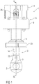
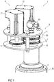
- FIGS. 1 and 2 show a trained example of a cleaning device or cleaning robot cleaning device 1 for cleaning by means of a cleaning fluid F, which can be cleaned by means of this cleaning device 1, in particular hollow body, in particular can be carried out an internal cleaning such hollow body, ie it can be an interior of the hollow body to be cleaned, in particular an inner wall and / or interior parts.
- the hollow body may be formed, for example, as a container, tank, container, keg, as a plant and / or machine and / or as another hollow body.
- a cleaning device 1 is also referred to as a target jet cleaner.
- the cleaning device 1 flowing through the cleaning liquid F is in the FIGS. 7 to 9 hatched shown.
- the cleaning device 1 is in FIG. 1 in a side view and in FIG. 2 shown in a longitudinal sectional view.
- the FIGS. 3 to 9 each show detailed representations of different areas of this cleaning device 1, wherein the FIGS. 7 to 9 various embodiments of a cleaning head 2 of this cleaning device 1 show.
- the Figures 10 and 11 show the cleaning device 1 with a further embodiment of a tubular portion 3, which will be described in more detail below.
- the cleaning device 1 comprises a support housing 4, which serves in particular for arranging and holding the cleaning device 1 in an opening of the hollow body to be cleaned.
- the tubular portion 3 is introduced with the cleaning head 2 through the opening in the interior of the hollow body to be cleaned.
- the support housing 4 is, for example, with a formed flange, in particular with a mounting terminal 23, placed on an opening edge and attached, for example, to be cleaned hollow body, so that the cleaning device 1 is held stable during cleaning on the hollow body to be cleaned.
- the mounting connection 23 is designed, for example, as a connection screw connection in order to connect the cleaning device 1 by screwing to the hollow body.
- the tubular or rod-shaped section 3, d. H. the elongated, at least substantially rotationally symmetrical, section of the cleaning device 1 is, in particular with a drive end region, arranged in the support housing 4 and extends downwards, d. H. along its longitudinal extent, out of the support housing 4.
- a spray arm 5 rotatable about an at least substantially perpendicular to the first axis of rotation Z and thus substantially horizontally oriented second axis of rotation X is arranged.
- a drive device 6 for driving the cleaning head 2 and the spray arm 5 is arranged on the drive end region of the tubular section 3 opposite the cleaning head end region.
- This drive device 6 comprises a gear arrangement 7, which is arranged in a gear housing 8 on an upper side of the support housing 4, and a motor arrangement 9, which is arranged on an upper side of the gear housing 8.
- the gear arrangement 7 comprises two independent drive motor side gear 10, 11 and the motor assembly 9 two independent drive units, in particular drive motors 12, 13, each drive unit, in the example shown each drive motor 12, 13, each with a drive motor side gear 10, 11 is coupled , so that the cleaning device 1 two independent and advantageously having separately controllable and / or controllable drive arrangements.
- One of the drive arrangements serves to drive the cleaning head 2 and the other drive arrangement serves to drive the spray arm 5.
- the respective drive unit is designed in particular as an electrical, pneumatic and / or hydraulic drive unit.
- the respective drive unit 12, 13 designed as a drive unit is designed as an electric motor.
- the respective drive unit formed as a drive motor 12, 13 may be formed, for example, as a pneumatic motor or hydraulic motor.
- the respective drive unit can be designed, for example, as a turbine, in particular as a hydraulically operated turbine and thus as a hydraulic drive unit designed as a turbine.
- the two drive units can be identical or different.
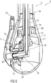
- the tubular section 3 comprises an outer hollow shaft 14, which is rotatably mounted in the support housing 4 about its axis of rotation, which corresponds to the first axis of rotation Z. It is connected to the cleaning head 2, in particular rotatably connected, and coupled via the first drive motor side gear 10 with the first drive motor 12 formed as the first drive unit for driving the cleaning head 2, as in the Figures 2 and 4 shown.
- an inner hollow shaft 15 is arranged, which is rotatably mounted relative to the outer hollow shaft 14 about its axis of rotation corresponding to the first axis of rotation Z, ie, the hollow shaft 15 is coaxially disposed in the hollow shaft 14, wherein the hollow shaft 14 and inner hollow shaft 15 independently are rotatable.
- the inner hollow shaft 15 and the cleaning head 2 are rotatable independently. This is achieved via a corresponding bearing 30 between inner hollow shaft 15 and cleaning head 2.
- This hollow shaft 15 is coupled via a sprüharm familiares gear 16 with the spray arm 5 and the second drive motor-side gear 11 is coupled to the second drive unit designed as a second drive unit 13 for driving the spray arm 5.
- the drive motor side gear 10, 11 each have a drive gear 17, 18 and a driven gear 19, 20 on.
- the drive gear 17 of the first drive-motor-side transmission 10 is, in particular via a first drive shaft, coupled to the first drive motor 12 formed as the first drive unit.
- the drive gear 18 of the second drive-motor-side transmission 11 is coupled, in particular via a second drive shaft, with the second drive unit designed as a second drive motor 13.
- the output gear 19 of the first drive motor side gear 10 is coupled to the outer hollow shaft 14, in particular arranged on this.
- the output gear 20 of the second drive motor side gear 11 is coupled to the inner hollow shaft 15, in particular arranged on this.
- the sprüharm populare gear 16 is designed as a crown gear, also referred to as crown gear, wherein on the inner hollow shaft 15, a spindle or spur gear 21 is arranged and arranged on the spray arm 5, more precisely on a rotatably mounted in the cleaning head 2 region of the spray arm 5, a crown wheel 22 is, also referred to as Kronenrad.
- a deflection from the vertical first rotational axis Z of the inner hollow shaft 15 to the horizontal second rotational axis X of the spray arm 5 is achieved.
- the alternative arrangement of spur gear 21 and crown wheel 22, d. H. the spur gear 21 on the spray arm 5 and the crown wheel 22 on the inner hollow shaft 15, would also be possible.
- a bevel gear would be possible or it may be another form of redirecting the rotational movement of the vertically disposed inner hollow shaft 15 on the cleaning head 2 horizontally extending portion of the spray arm 5 may be provided.
- a cleaning liquid line 24 for the cleaning liquid F passes through the tubular portion 3, through the cleaning head 2 and through the Spray arm 5 through and opens into at least one outlet opening 25 of the spray arm 5.
- the cleaning fluid line 24 is disposed in the tubular portion 3 in the inner hollow shaft 15, ie it passes through it. It is thus coaxial with the inner hollow shaft 15 and thus also arranged coaxially with the outer hollow shaft 14.
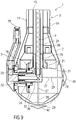
- This cleaning fluid line 24 is liquid-tight with respect to a cleaning device interior, in particular with respect to the inner hollow shaft 15 and thus also with respect to the outer hollow shaft 14, with respect to the gear assembly 7, through which it passes, with respect to the sprüharm desken transmission 16, through which it also passes, with respect to an interior the cleaning head 2 and in particular with respect to bearings, which allow the rotation of the inner hollow shaft 15, the outer hollow shaft 14, the cleaning head 2 and the spray arm 5.
- the cleaning fluid line 24 extends from a connection element 26, for example a fluid connection, for supplying the cleaning fluid F through the transmission housing 8, through the two output gears 19, 20, through the inner hollow shaft 15 and thus also through the outer hollow shaft 14, in which the inner hollow shaft 15 is arranged , through the spur gear 21, is then angled towards the crown wheel 22 and passes therethrough and through the spray arm 5 to its outlet opening 25.
- the described course forms a main line section of the cleaning fluid line 24, from which one or more self-cleaning line sections 27 to further outlet openings 28 on the cleaning head 2 and / or on the spray arm 5 can branch off, as will be described in more detail below.
- a further outlet opening 28 may be provided directly on the main line section, for example, as in the FIGS. 7 to 9 shown on the spray arm 5.
- the cleaning fluid line 24 is thus designed as a line which is completely closed, ie encapsulated, relative to the cleaning device interior, for example as a cleaning fluid tube, cleaning fluid tube or cleaning fluid channel. It thus has its own, within the cleaning device 1 completely closed line wall 29.
- This conduit wall 29 is spaced from an inner side of the inner hollow shaft 15 to allow the inner hollow shaft 15 to rotate without grinding on the cleaning fluid conduit 24, because the portion of the cleaning fluid conduit 24 passing through the tubular portion 3 does not rotate, neither with the outer hollow shaft 14 nor with the Inner hollow shaft 15.
- the spacing of inner hollow shaft 15 and cleaning fluid line 24 and the thus enabled rotation of the hollow shaft 15 relative to the stationary cleaning fluid line 24, without damaging them, is achieved by a bearing 31 between inner hollow shaft 15 and conduit wall 29.
- the conduit wall 29 encloses a conduit interior, which is provided exclusively for the flow through, in particular for the passage of the cleaning fluid F.
- the cleaning fluid line 24 is hollow inside, it has a free cross section and free diameter.
- no other cleaning device component is arranged, in particular no drive component, in particular no drive shaft, no transmission component, no transmission, no bearing component and no bearing, ie in particular no required for rotating the cleaning head 2 and / or the spray arm 5 and especially for this self-moving component.
- This refinement of the cleaning fluid line 24 prevents the cleaning fluid F from coming into contact with cleaning device components in the interior of the cleaning device 1, in particular with the abovementioned components which are required for the rotation of the cleaning head 2 and the spray arm 5. This avoids that from the hollow body to be cleaned dissolved particles with the reused, d. H. in recirculation mode returned to the cleaning device 1, cleaning liquid F are transported to these cleaning device components and pollute them and thereby damage or block.
- the outer hollow shaft 14, overlapping a flange region of the cleaning head 2 is connected to the cleaning head 2.
- the flange portion of the cleaning head 2 is screwed into the outer hollow shaft 14.
- a press-fit sleeve 32 with a sealing lip 33 is arranged at a transition region from a section fixed in the cleaning head 2 into a section of the cleaning fluid line 24 rotating with the spray arm 5 in order to prevent the cleaning fluid F from escaping. moreover are in a recess of this press-in sleeve 32, a sealing element 34 and a support member 35 is arranged.
- a seal 36 is arranged at an opening region through which the spray arm 5 is guided into the cleaning head 2, in order to prevent penetration of the cleaning fluid F from the outside into the cleaning device interior also via this opening.
- a seal 37 is also arranged between the support housing 4 and the outer hollow shaft 14 in order to prevent a penetration of the cleaning fluid F between the outer hollow shaft 14 and support housing 4 in the support housing 4 and from there into the transmission housing 8 and into the tubular portion 3. This ensures that the cleaning fluid F is guided within the cleaning device 1 exclusively in the cleaning fluid line 24.
- the cleaning device 1 furthermore has sensors 38 for determining a rotational position of the cleaning head 2 and a rotational position of the spray arm 5. These are arranged in the illustrated example in the gear housing 8, in particular in the region of the respective drive motor side gear 10, 11. They detect, for example, revolutions of the respective drive gear 17, 18 and / or driven gear 19, 20 and / or the respective drive shaft. This makes it possible, for example, to determine a respective rotational position of the cleaning head 2 and of the spray arm 5 and thus a respective direction of the jet of spray liquid sprayed on the spray arm 5.
- the cleaning device 1 has a pressure sensor 39 for determining a pressure of the cleaning liquid F sprayed by the spray arm 5, as in FIG FIG. 2 shown.
- this pressure sensor 39 for example a pressure measuring cell, is arranged in the support housing 4, more precisely at an underside of the support housing 4 within a region enclosed by the mounting connection 23 and thus during the cleaning before the opening of the hollow body, through which the Cleaning device 1 is introduced.
- the pressure sensor 39 is aligned in the direction of the cleaning head 2 with spray arm 5.
- the cleaning device 1 may for example have a self-cleaning function, in particular to clean outer areas of the cleaning head 2 or to protect against contamination.
- a further outlet opening 28 in cleaning fluid line 24 is provided on spray arm 5, which is formed on a lower region of spray arm 5, that of end-side outlet opening 25 for spraying the cleaning liquid F is provided for cleaning the hollow body, is complained of, as in the FIGS. 7 to 9 shown.
- This further outlet opening 28 is aligned in the direction of the cleaning head 2 and sprays a portion of the outside of the cleaning head 2, on which the spray arm 5 moves past. As a result, in particular an attachment of particles between the spray arm 5 and cleaning head 2 and thus blocking the rotational movement of the spray arm 5 is prevented.
- At least one, in the illustrated example at least substantially horizontally extending, Self-cleaning line section 27 is provided in the cleaning head 2, which branches off from the main line section of the cleaning fluid line 24 and opens in a further outlet opening 28 on the cleaning head 2.
- the cleaning fluid F is led laterally to the outside of the cleaning head 2 in order to clean it, in particular its outer surface, and / or to prevent the contamination.
- a plurality of such substantially horizontal self-cleaning line sections 27 are provided, which open into distributed around the cleaning head 2 further outlet openings 28 to spray a lateral outer surface of the cleaning head 2 as fully as possible with the cleaning liquid F.
- an at least substantially vertically extending self-cleaning line section 27 is provided in the cleaning head 2, which branches off from the main line section of the cleaning fluid line 24 and opens in a further outlet opening 28 at an underside of the cleaning head 2.
- the cleaning liquid F is also passed to the lower outside of the cleaning head 2, to clean it and / or to prevent contamination.
- a baffle plate 40 is arranged on the outside of the cleaning head 2 in front of the respective further outlet opening 28 of the respective self-cleaning line section 27 and spaced apart from this respective further outlet opening 28, as in FIGS FIGS. 8 and 9 shown.
- the cleaning liquid F exiting from the respective further outlet opening 28 bounces against a side of the respective baffle plate 40 facing the respective further outlet opening 28 and bounces off the latter in the direction of the outer surface of the cleaning head 2.
- the outer surface of the cleaning head 2 is sprayed with the cleaning liquid F, whereby deposited particles are removed and / or the attachment of particles is prevented.
- the tubular portion 3 telescopically formed, in particular as a telescopic tube assembly of a plurality of axially displaceable relative to each other and advantageously interlocking intermeshing tubular elements 41.
- This telescoping is independent of one or more features described above possible.
- both the inner hollow shaft 15 and the outer hollow shaft 14 are formed correspondingly telescopic.
- a flexible shaft or a Teleskopfaltenbalg be provided for the respective torque transmission.
- the cleaning fluid line 24 is to enable this telescoping, in the region of this telescopic tubular portion 3, for example, also telescopically formed in the manner described, or it is for example flexible in the axial direction, for example as a flexible hose, the conduit wall 29 stretchable and / or foldable in the axial direction.
- This telescoping allows, advantageously in addition to the two independent rotational movements of cleaning head 2 and spray arm 5 about two axes, d. H. about the first rotation axis Z and the second rotation axis X, a translational movement along an axis, in particular along the first rotation axis Z, d. H. a translational movement of the cleaning head 2 with the spray arm 5 axially to the tubular portion and thereby lowering and raising the cleaning head 2 with the spray arm 5 in the hollow body to be cleaned.
- This translational movement ie the telescoping, can for example be done manually and / or by means of a telescopic drive 42, for example comprising a further drive motor, and thus in particular automatically.
- the telescopic drive 42 in particular a corresponding telescopic drive unit, for telescoping the tubular portion 3, ie for retraction and Extending, in particular in addition to the further drive motor, for example, a rope, a chain, a belt or a spindle.
- telescoping for example, internals in the hollow body to be cleaned, for example an agitator, can also be specifically cleaned from below by lowering the cleaning head 2 with the spray arm 5 in the hollow body by extending the telescoping tubular section 3.
- an immersion depth of the cleaning head 2 with the spray arm 5 in the hollow body to be cleaned for example, extendable, at least within the maximum telescopic length of the tubular portion 3.
- the described cleaning device 1 thus enables independently controllable and / or controllable rotations about two axes of rotation Z, X and, if the telescopability is present, also an automatic and / or manual vertical translational movement along the first axis of rotation Z.
- a needs-based Cleaning the inner surface of the hollow body allows, with individual areas can be targeted and stronger irradiated with the cleaning fluid F than other areas.
- any, in particular freely parameterizable, cleaning tracks and cleaning courses can be designed, which are then traversed by the jet of the cleaning agent. This would not be possible with transmission solutions, via which the rotation of the spray arm 5 is positively coupled with the rotation of the cleaning head 2.
- the cleaning device 1 By means of the cleaning device 1 thus a time and resource-optimized cleaning is possible, whereby downtime of a system to be cleaned can be reduced.
- an inline adaptation of the cleaning profile ie adaptation during cleaning, is possible, which enables adaptive cleaning.
- the cleaning device 1 which has the Telekopier sadness
- a stirrer also targeted to clean from below by the cleaning head 2 is lowered by the telescoping corresponding deep into the hollow body.
- the cleaning device 1 described has a simple and robust construction, which is freely scalable. Ie. the design of the cleaning device 1 is easily adaptable to any application, for example by producing the cleaning device 1 in the appropriate size. Changes in the basic functions are not required for this.
- the drive units, in particular drive motors 12, 13, of the cleaning device 1 are arranged fixed.
- an intelligent drive concept is achieved in which no rotary feedthroughs, such as slip rings, are required.
- the spray arm 5 advantageously has a curved shape, in particular a shape corresponding to the outer surface of the cleaning head 2, on which the spray arm 5 moves along, in particular in the Figures 2 . 5 and 7 to 9 shown.
- the spray arm 5 is thus curved so that its cleaning head 2 facing outer shape of the outer shape of the at least substantially spherical cleaning head 2 is adjusted, the spray arm 5 rests over its entire length on the cleaning head 2 or, as in the Figures 2 . 5 and 7 to 9 shown, only so slightly spaced to allow rotation of the spray arm 5 without grinding on the cleaning head 2.
- the liquid flow of the cleaning liquid F is encapsulated by the cleaning device 1, so that, in particular, gear components do not come into contact with the cleaning liquid F.
- introduction of wear-related abrasion of the gear components via the cleaning fluid F into the hollow body is avoided.
- a, at least substantially, constant flow cross-section is achieved and a flow around moving parts is avoided.
- lower pressure losses are achieved and turbulence of the cleaning fluid F can be avoided.
- an immersion depth of the cleaning head 2 in the hollow body is arbitrarily changeable, either by the provision of telescoping or by the outer hollow shaft 14, inner hollow shaft 15 and the running therein part of the cleaning fluid line 24 are replaced with correspondingly longer or shorter replacement parts ,
- FIG. 12 shows a further embodiment of the cleaning device 1, in which the cleaning device 1 has two spray arms 5.
- both spray arms 5 are arranged opposite one another on the cleaning head 2 and are thus arranged rotatable about the same at least substantially perpendicular to the first axis of rotation Z and thus substantially horizontally oriented second axis of rotation X. They are connected in the example shown with a rotatably mounted in the cleaning head 2 Sprüharmhohlwelle 43, which is aligned parallel to the second axis of rotation X and through which the cleaning fluid line 24 passes.
- this Sprüharmhohlwelle 43 is sealed and rotatably mounted in a arranged in the cleaning head 2 T-piece 44 of extending through the inner hollow shaft 15 and in the cleaning head 2 continuing portion of the cleaning fluid line 24, wherein a sealed in this T-piece 44 arranged area of Sprüharmhohlwelle 43rd at least one passage opening 45, in the example shown a plurality of passage openings 45, to the inflow of the cleaning fluid F from the extending through the hollow shaft 15 and in the cleaning head 2 further leading portion of the cleaning fluid line 24 in the Sprüharmhohlwelle 43 and thus in the section of the cleaning fluid line 24 enable.
- the spray arm hollow shaft 43 and are thus both spray arms 5 coupled via the sprüharmfelde gear 16 with the inner hollow shaft 15 and coupled via the second drive motor side gear 11 with the second drive motor 13 formed as the second drive unit for driving the spray arm 5.
- the sprüharm worne gear 16 is formed in this example as a bevel gear, wherein on the inner hollow shaft 15, a bevel gear 46 is arranged and on the Sprüharmwelle 43 a corresponding bevel gear 47 is arranged, which are in meshing engagement with each other.
- a deflection from the vertical first rotational axis Z of the hollow inner shaft 15 to the horizontal second rotational axis X of the Sprüharmhohlwelle 43 and thus the two spray arms 5 is achieved.
- a crown gear would also be possible or it may be another form of redirecting the rotational movement of the vertically disposed inner hollow shaft 15 may be provided on the cleaning head 2 horizontally extending Sprüharmhohlwelle 43.
Abstract
Die Erfindung betrifft eine Reinigungsvorrichtung (1) zur Reinigung mit einer Reinigungsflüssigkeit (F), insbesondere zur Reinigung von Hohlkörpern, umfassend einen rohrförmigen Abschnitt (3), einen um eine erste Rotationsachse (Z) rotierbaren Reinigungskopf (2) an einem Reinigungskopfendbereich des rohrförmigen Abschnitts (3), mindestens einen um eine zumindest im Wesentlichen senkrecht zur ersten Rotationsachse (Z) ausgerichtete zweite Rotationsachse (X) rotierbaren Sprüharm (5) am Reinigungskopf (2), eine Antriebsvorrichtung (6) zum Antrieb des Reinigungskopfes (2) und des Sprüharms (5) an einem dem Reinigungskopfendbereich gegenüberliegenden Antriebsendbereich des rohrförmigen Abschnitts (3) und eine Reinigungsflüssigkeitsleitung (24) für die Reinigungsflüssigkeit (F), welche durch den rohrförmigen Abschnitt (3) hindurch verläuft.Erfindungsgemäß verläuft die Reinigungsflüssigkeitsleitung (24) zudem durch den Reinigungskopf (2) und den Sprüharm (5) hindurch und mündet in mindestens einer Austrittsöffnung (25), wobei die Reinigungsflüssigkeitsleitung (24) gegenüber einem Reinigungsvorrichtungsinnenraum flüssigkeitsdicht ausgebildet ist und wobei alle Reinigungsvorrichtungskomponenten außerhalb der Reinigungsflüssigkeitsleitung (24) angeordnet sind.The invention relates to a cleaning device (1) for cleaning with a cleaning liquid (F), in particular for cleaning hollow bodies, comprising a tubular section (3), a cleaning head (2) rotatable about a first rotation axis (Z) on a cleaning head end region of the tubular section (3), at least one spray arm (5) rotatable about an at least substantially perpendicular to the first axis of rotation (Z) aligned rotary axis (X) on the cleaning head (2), a drive device (6) for driving the cleaning head (2) and the spray arm (5) at a driving end portion of the tubular portion (3) opposite to the cleaning head end portion and a cleaning liquid (24) for the cleaning liquid (F) passing through the tubular portion (3). According to the invention, the cleaning liquid pipe (24) also passes through the cleaning head (2) and the spray arm (5) through and mü In at least one outlet opening (25), wherein the cleaning fluid line (24) is formed liquid-tight with respect to a cleaning device interior and wherein all cleaning device components outside the cleaning fluid line (24) are arranged.
Description
Die Erfindung betrifft eine Reinigungsvorrichtung nach den Merkmalen des Oberbegriffs des Anspruchs 1.The invention relates to a cleaning device according to the features of the preamble of
Aus dem Stand der Technik sind, wie in der
Der Erfindung liegt die Aufgabe zu Grunde, eine gegenüber dem Stand der Technik verbesserte Reinigungsvorrichtung anzugeben.The object of the invention is to specify a cleaning device which is improved over the prior art.
Die Aufgabe wird erfindungsgemäß gelöst durch eine Reinigungsvorrichtung mit den Merkmalen des Anspruchs 1.The object is achieved by a cleaning device with the features of
Vorteilhafte Ausgestaltungen der Erfindung sind Gegenstand der Unteransprüche.Advantageous embodiments of the invention are the subject of the dependent claims.
Eine Reinigungsvorrichtung zur Reinigung mit einer Reinigungsflüssigkeit, insbesondere zur Reinigung, insbesondere Innenreinigung, von Hohlkörpern, umfasst einen rohrförmigen Abschnitt, mindestens einen um eine erste Rotationsachse rotierbaren Reinigungskopf an einem Reinigungskopfendbereich des rohrförmigen Abschnitts, einen Sprüharm, welcher um eine zumindest im Wesentlichen senkrecht zur ersten Rotationsachse ausgerichtete zweite Rotationsachse rotierbar am Reinigungskopf angeordnet ist, eine Antriebsvorrichtung zum Antrieb des Reinigungskopfes und des Sprüharms an einem dem Reinigungskopfendbereich gegenüberliegenden Antriebsendbereich des rohrförmigen Abschnitts und eine Reinigungsflüssigkeitsleitung für die Reinigungsflüssigkeit, welche durch den rohrförmigen Abschnitt hindurch verläuft.A cleaning device for cleaning with a cleaning liquid, in particular for cleaning, in particular internal cleaning, of hollow bodies, comprises a tubular section, at least one cleaning head rotatable about a first axis of rotation on a cleaning head end region of the tubular section, a spray arm which is at least substantially perpendicular to the first Rotary axis aligned second axis of rotation is rotatably mounted on the cleaning head, a drive device for driving the cleaning head and the spray arm at a cleaning head end region opposite drive end of the tubular portion and a cleaning liquid line for the cleaning liquid, which passes through the tubular portion.
Erfindungsgemäß verläuft die Reinigungsflüssigkeitsleitung zudem durch den Reinigungskopf und den Sprüharm hindurch und mündet in mindestens einer Austrittsöffnung, wobei die Reinigungsflüssigkeitsleitung gegenüber einem Reinigungsvorrichtungsinnenraum flüssigkeitsdicht ausgebildet ist. Vorteilhafterweise sind alle Reinigungsvorrichtungskomponenten außerhalb der Reinigungsflüssigkeitsleitung angeordnet.According to the invention, the cleaning fluid line also passes through the cleaning head and the spray arm and opens into at least one outlet opening, wherein the cleaning fluid line is designed to be liquid-tight with respect to a cleaning device interior. Advantageously, all cleaning device components are arranged outside the cleaning fluid line.
Die Reinigungsflüssigkeitsleitung ist somit als eine gegenüber dem Reinigungsvorrichtungsinnenraum vollständig geschlossene Leitung ausgebildet, beispielsweise rohrförmig, schlauchförmig oder kanalförmig, beispielsweise als ein Reinigungsflüssigkeitsrohr, Reinigungsflüssigkeitsschlauch oder Reinigungsflüssigkeitskanal. Sie weist somit eine eigene, innerhalb der Reinigungsvorrichtung vollständig geschlossene Leitungswand auf. Diese Leitungswand umschließt einen Leitungsinnenraum, welcher ausschließlich zum Durchströmen, insbesondere zum Durchströmen der Reinigungsflüssigkeit, vorgesehen ist. In diesem von der Leitungswand umschlossenen Leitungsinnenraum ist keine andere Reinigungsvorrichtungskomponente angeordnet, insbesondere keine Antriebskomponente, insbesondere keine Antriebswelle, keine Getriebekomponente, kein Getriebe, keine Lagerkomponente und kein Lager, d. h. insbesondere keine zum Rotieren des Reinigungskopfes und/oder des Sprüharms erforderliche und insbesondere hierfür selbst bewegliche Komponente.The cleaning fluid line is thus formed as a relative to the cleaning device interior completely closed line, for example tubular, tubular or channel-shaped, for example as a cleaning fluid tube, cleaning fluid tube or cleaning fluid channel. It thus has its own, within the cleaning device completely closed pipe wall. This conduit wall encloses a line interior, which is provided exclusively for the flow through, in particular for the passage of the cleaning liquid. In this line space enclosed by the conduit wall no other cleaning device component is arranged, in particular no drive component, in particular no drive shaft, no transmission component, no transmission, no bearing component and no bearing, ie in particular no required for rotating the cleaning head and / or the spray arm and in particular for this self-moving component.
Aus dem Stand der Technik ist es bekannt, die Reinigungsflüssigkeit derart durch den rohrförmigen Abschnitt, den Reinigungskopf und den Sprüharm zu leiten, dass Antriebskomponenten, welche zum Antrieb der Rotationsbewegung des Reinigungskopfes und des Sprüharms erforderlich sind, beispielsweise Wellen, Achsen, Getriebe oder Getriebeteile, insbesondere Zahnräder und/oder Schnecken, und/oder Lager oder Lagerteile, von der Reinigungsflüssigkeit umspült sind. Beispielsweise wird die Reinigungsflüssigkeit zur Schmierung dieser Teile, beispielsweise von Getriebe und Lagern, verwendet. Hierzu wird der Reinigungsvorrichtungsinnenraum oder werden wesentliche Bereiche des Reinigungsvorrichtungsinnenraums, in denen diese Reinigungsvorrichtungskomponenten angeordnet sind, mit der Reinigungsflüssigkeit geflutet.From the prior art it is known to direct the cleaning fluid through the tubular portion, the cleaning head and the spray arm in such a way that drive components required for driving the rotary motion of the cleaning head and the spray arm, for example shafts, axles, gears or gear parts, in particular gears and / or worms, and / or bearings or bearing parts, are washed by the cleaning fluid. For example, the cleaning fluid is used to lubricate these parts, such as gears and bearings. For this purpose, the cleaning device interior or essential areas of the cleaning device interior, in which these cleaning device components are arranged, are flooded with the cleaning liquid.
Dieses Umströmen derartiger Reinigungsvorrichtungskomponenten, insbesondere von Getriebeteilen, wird durch die erfindungsgemäße Lösung vermieden, da ein Flüssigkeitsstrom der Reinigungsflüssigkeit durch die Reinigungsvorrichtung hindurch gekapselt erfolgt. Dadurch wird vermieden, dass ein verschleißbedingter Abrieb von den Getriebeteilen durch die Reinigungsflüssigkeit aus der Reinigungsvorrichtung ausgespült wird und somit zusammen mit der Reinigungsflüssigkeit in den zu reinigenden Hohlkörper gelangt und beispielsweise ein anschließend darin eingefülltes Produkt verschmutzt.This flow around such cleaning device components, in particular of transmission parts, is avoided by the solution according to the invention, since a liquid flow of the cleaning liquid through the cleaning device is carried out by encapsulated. This avoids that a wear-related abrasion is flushed out of the gear parts by the cleaning liquid from the cleaning device and thus enters together with the cleaning liquid in the hollow body to be cleaned and dirty, for example, a product subsequently filled therein.
Des Weiteren wird durch die erfindungsgemäße Lösung ein, zumindest im Wesentlichen, gleich bleibender Strömungsquerschnitt der Reinigungsflüssigkeitsleitung erreicht, wodurch Druckverluste verringert werden. Zudem wird ein Verwirbeln der Reinigungsflüssigkeit und eine daraus resultierende Strömungsstörung durch in der Reinigungsflüssigkeitsleitung angeordnete und insbesondere sich darin bewegende Reinigungsvorrichtungskomponenten vermieden, da bei der erfindungsgemäßen Lösung keine solchen Reinigungsvorrichtungskomponenten in der Reinigungsflüssigkeitsleitung vorhanden sind.Furthermore, the solution according to the invention achieves, at least substantially, a constant flow cross-section of the cleaning fluid line, as a result of which pressure losses are reduced. In addition, a swirling of the cleaning liquid and a resulting flow disturbance is arranged in the cleaning liquid line and in particular moving therein Cleaning device components avoided because in the inventive solution no such cleaning device components are present in the cleaning fluid line.
Zudem besteht bei dem oben beschriebenen Umspülen der genannten Reinigungsvorrichtungskomponenten mit der Reinigungsflüssigkeit im Stand der Technik die Gefahr, dass sich durch die Reinigung des Hohlkörpers aus diesem entfernte Produktreste an diesen Reinigungsvorrichtungskomponenten, beispielsweise im Getriebe, festsetzen, wodurch hygienische Risiken und zudem die Gefahr eines Ausfalls dieser Reinigungsvorrichtungskomponenten, beispielsweise des Getriebes, besteht. Diese Gefahr besteht, da die Reinigung von Hohlkörpern, beispielsweise Tanks, mittels der Reinigungsvorrichtung üblicherweise im Kreislauf erfolgt, d. h. es erfolgt keine verlorene Reinigung, sondern die Reinigungsflüssigkeit wird wiederverwendet. Da eingebaute Filter nicht alle Produktreste aus der Reinigungsflüssigkeit herausfiltern, gelangen diese wieder in den Kreislauf, wodurch die geschilderte Verschmutzungsgefahr bei aus dem Stand der Technik bekannten Reinigungsvorrichtungen besteht. Auch dies wird durch die erfindungsgemäße Lösung vermieden, da hier ein Kontakt der Reinigungsflüssigkeit mit diesen Reinigungsvorrichtungskomponenten vermieden ist.In addition, there is the danger in the above-described flushing of said cleaning device components with the cleaning liquid in the prior art, the danger that settle by cleaning the hollow body from this remote product residues on these cleaner components, for example in the transmission, creating hygienic risks and also the risk of failure this cleaner components, such as the transmission consists. This danger exists, since the cleaning of hollow bodies, for example tanks, by means of the cleaning device usually takes place in the circulation, d. H. There is no lost cleaning, but the cleaning liquid is reused. Since built-in filters do not filter out all product residues from the cleaning liquid, they return to the circulation, whereby the described risk of contamination exists in cleaning devices known from the prior art. This is also avoided by the solution according to the invention, since contact of the cleaning liquid with these cleaning device components is avoided here.
Die Reinigungsflüssigkeitsleitung verläuft insbesondere vollständig durch den rohrförmigen Abschnitt hindurch, d. h. vom Antriebsendbereich bis zum Reinigungskopfendbereich. Sie tritt somit insbesondere am Antriebsendbereich in Axialrichtung des rohrförmigen Abschnitts in diesen ein und am Reinigungskopfendbereich in Axialrichtung des rohrförmigen Abschnitts aus diesem aus. Dadurch ist insbesondere ein seitlicher, d. h. radial zum rohrförmigen Abschnitt, verlaufender Eintritt der Reinigungsflüssigkeitsleitung in den rohrförmigen Abschnitt und ein damit verbundenes Kreuzen im rohrförmigen Abschnitt rotierender Komponenten oder ein Eintritt in diese rotierenden Komponenten, beispielsweise verbunden mit aufwändigen Abdichtungsmaßnahmen, vermieden.In particular, the cleaning fluid line runs completely through the tubular section, ie from the drive end area to the cleaning head end area. Thus, it enters the drive end portion in the axial direction of the tubular portion, and the end portion of the cleaning head in the axial direction of the tubular portion thereof. As a result, in particular a lateral, ie radially to the tubular portion, extending entry of the cleaning liquid line in the tubular portion and an associated crossing in the tubular portion of rotating components or entry into these rotating components, for example, associated with elaborate sealing measures avoided.
In einer Ausführungsform sind der rohrförmige Abschnitt, der Reinigungskopf und der mindestens eine Sprüharm mit Ausnahme der mindestens einen Austrittsöffnung gegenüber einer äußeren Umgebung flüssigkeitsdicht verschlossen. Somit ist insbesondere der Reinigungsvorrichtungsinnenraum gegenüber der äußeren Umgebung flüssigkeitsdicht verschlossen. Durch die oben beschriebene gekapselte Ausführung der Reinigungsflüssigkeitsleitung wird das Eindringen der Reinigungsflüssigkeit und beispielsweise von aus dem zu reinigenden Hohlkörper entfernten Verschmutzungen in den Reinigungsvorrichtungsinnenraum vermieden. Durch die flüssigkeitsdicht verschlossene Ausbildung des rohrförmigen Abschnitts, des Reinigungskopfes und des mindestens einen Sprüharms mit Ausnahme der mindestens einen Austrittsöffnung gegenüber der äußeren Umgebung wird auch das Eindringen der mittels der Reinigungsvorrichtung versprühten Reinigungsflüssigkeit und beispielsweise der aus dem zu reinigenden Hohlkörper entfernten Verschmutzungen von außen, aus der äußeren Umgebung der Reinigungsvorrichtung, in den Reinigungsvorrichtungsinnenraum vermieden. Dadurch wird die Verschmutzung und die daraus resultierende Gefahr des Ausfalls von insbesondere für die Rotationsbewegung von Reinigungskopf und Sprüharm erforderlichen Reinigungsvorrichtungskomponenten, insbesondere Getriebe- und/oder Lagerkomponenten, vermieden. Dies wird insbesondere dadurch erreicht, dass der Reinigungsvorrichtungsinnenraum auf die beschriebene Weise nach außen, d. h. gegenüber der äußeren Umgebung flüssigkeitsdicht verschlossen und somit gekapselt ausgebildet ist.In one embodiment, the tubular section, the cleaning head and the at least one spray arm, with the exception of the at least one outlet opening, are closed in a liquid-tight manner with respect to an external environment. Thus, in particular the cleaning device interior is liquid-tightly sealed against the external environment. The above-described encapsulated embodiment of the cleaning fluid line prevents the penetration of the cleaning fluid and, for example, contaminants removed from the hollow body to be cleaned into the cleaning device interior. Due to the liquid-tight closed design of the tubular portion, the cleaning head and the at least one spray arm with the exception of the at least one outlet opening to the outside environment and the penetration of sprayed by the cleaning device cleaning liquid and, for example, removed from the hollow body to be cleaned contaminants from the outside, from the external environment of the cleaning device, avoided in the cleaner interior. As a result, the contamination and the resulting risk of failure of cleaning device components, in particular transmission and / or bearing components, required in particular for the rotational movement of the cleaning head and the spray arm are avoided. This is achieved in particular in that the cleaning device interior in the manner described outwardly, d. H. sealed liquid-tight against the external environment and thus formed encapsulated.
Zweckmäßigerweise sind daher alle für die Rotationsbewegung des Reinigungskopfes und des zumindest einen Sprüharms erforderlichen Reinigungsvorrichtungskomponenten, insbesondere Getriebe- und/oder Lagerkomponenten, beispielsweise Lager und/oder Zahnräder, innerhalb dieses gegenüber der äußeren Umgebung flüssigkeitsdichten Verschlusses des rohrförmigen Abschnitts, der Reinigungskopfes und des mindestens einen Sprüharms und somit insbesondere innerhalb des gegenüber der äußeren Umgebung flüssigkeitsdicht verschlossenen und somit vorteilhafterweise gekapselt ausgebildeten Reinigungsvorrichtungsinnenraums angeordnet sind.Conveniently, therefore, all required for the rotational movement of the cleaning head and the at least one Sprüharms cleaning device components, in particular gear and / or bearing components, such as bearings and / or gears, within this relative to the external environment liquid-tight closure of the tubular portion, the cleaning head and the at least one Sprüharms and thus especially within the opposite to the outer Environment liquid-tightly sealed and thus advantageously encapsulated trained cleaning device interior are arranged.
In einer Ausführungsform umfasst die Reinigungsvorrichtung zwei voneinander unabhängige, insbesondere vollkommen voneinander unabhängige, Antriebsanordnungen, d. h. eine Antriebsanordnung zum Antrieb des Reinigungskopfes und eine weitere Antriebsanordnung zum Antrieb des Sprüharms. Die beiden Antriebsanordnungen umfassen insbesondere jeweils eine Antriebseinheit, insbesondere jeweils einen Antriebsmotor. Dadurch können die Rotationsbewegungen von Reinigungskopf und Sprüharm unabhängig voneinander durchgeführt werden, insbesondere können Rotationsgeschwindigkeiten von Reinigungskopf und Sprüharm unabhängig voneinander eingestellt werden, insbesondere unabhängig voneinander gesteuert und/oder geregelt werden. Insbesondere können die Rotationsbewegungen von Reinigungskopf und mindestens einem Sprüharm derart unabhängig voneinander durchgeführt werden, dass sie sich nicht gegenseitig beeinflussen. Die jeweilige Antriebseinheit ist insbesondere als eine elektrische, pneumatische und/oder hydraulische Antriebseinheit ausgebildet. Insbesondere ist die jeweilige als Antriebsmotor ausgebildete Antriebseinheit als ein Elektromotor ausgebildet. In anderen Ausführungsformen kann die jeweilige als Antriebsmotor ausgebildete Antriebseinheit beispielsweise als ein Pneumatikmotor oder Hydraulikmotor ausgebildet sein. In anderen Ausführungsbeispielen kann die jeweilige Antriebseinheit beispielsweise als eine Turbine ausgebildet sein, insbesondere als eine hydraulisch betriebene Turbine und somit als eine als Turbine ausgebildete hydraulische Antriebseinheit. Die beiden Antriebseinheiten können gleich oder verschieden ausgebildet sein.In one embodiment, the cleaning device comprises two mutually independent, in particular completely independent, drive arrangements, d. H. a drive arrangement for driving the cleaning head and a further drive arrangement for driving the spray arm. In particular, the two drive arrangements each comprise a drive unit, in particular in each case a drive motor. As a result, the rotational movements of the cleaning head and the spray arm can be carried out independently of one another; in particular, rotational speeds of the cleaning head and the spray arm can be adjusted independently of one another, in particular independently controlled and / or regulated. In particular, the rotational movements of the cleaning head and at least one spray arm can be carried out independently of one another such that they do not influence one another. The respective drive unit is designed in particular as an electrical, pneumatic and / or hydraulic drive unit. In particular, the respective drive unit designed as a drive motor is designed as an electric motor. In other embodiments, the respective drive unit designed as a drive motor may be designed, for example, as a pneumatic motor or hydraulic motor. In other exemplary embodiments, the respective drive unit can be designed, for example, as a turbine, in particular as a hydraulically operated turbine and thus as a hydraulic drive unit designed as a turbine. The two drive units can be identical or different.
Die Reinigungsvorrichtung ermöglicht somit unabhängig voneinander steuerbare und/oder regelbare Rotationsbewegungen um zwei Rotationsachsen, insbesondere um die vertikale erste Rotationsachse und die horizontale zweite Rotationsachse. Bei aus dem Stand der Technik bekannten Reinigungsvorrichtungen liegt eine Zwangskopplung zwischen der Rotationsbewegung des Reinigungskopfes und der Rotationsbewegung des Sprüharms vor. Daraus ergeben sich fest vorgegebene Reinigungsbahnen, welcher ein Strahl der von dem Sprüharm versprühten Reinigungsflüssigkeit beschreibt. Durch den Antrieb des Reinigungskopfes und des Sprüharms unabhängig voneinander wird im Gegensatz dazu eine bedarfsgerechte und/oder adaptive Reinigung ermöglicht.The cleaning device thus allows independently controllable and / or controllable rotational movements about two axes of rotation, in particular about the vertical first axis of rotation and the horizontal second axis of rotation. In known from the prior art cleaning devices is a forced coupling between the rotational movement of the cleaning head and the Rotational movement of the spray arm before. This results in fixed predetermined cleaning paths, which describes a jet of sprayed from the spray arm cleaning fluid. By driving the cleaning head and the spray arm independently of each other, on the contrary, a needs-based and / or adaptive cleaning is made possible.
Beispielsweise weist der zu reinigende Hohlkörper Bereiche auf, die intensiver gereinigt werden müssen, beispielsweise Bereiche, in denen sich Produktreste verstärkt ablagern, und/oder Rührwerke, Stutzen, Mannlöcher und/oder andere Öffnungen, in deren Bereich eine Oberflächenform eine Reinigung erschwert, und/oder Bereiche, an denen Sensoren angeordnet sind. Durch den Antrieb des Reinigungskopfes und des Sprüharmes unabhängig voneinander können der Reinigungskopf und der Sprüharm derart rotiert werden, dass der Strahl der vom Sprüharm versprühten Reinigungsflüssigkeit verstärkt auf diese Bereiche gerichtet wird, denn der Strahl der Reinigungsflüssigkeit kann gezielt auf jeden Punkt einer Oberfläche des Hohlkörpers gerichtet werden. In Kombination mit einer geeigneten Sensorik ist auch eine Anpassung des Reinigungsprofils während der Reinigung, d. h. inline, möglich, so dass eine adaptive Reinigung erreicht wird.For example, the hollow body to be cleaned has areas that need to be cleaned more intensively, for example areas in which product residues are increasingly deposited, and / or agitators, nozzles, manholes and / or other openings in whose area a surface shape makes cleaning more difficult, and / or or areas where sensors are located. By driving the cleaning head and the spray arm independently of one another, the cleaning head and the spray arm can be rotated in such a way that the jet of the cleaning liquid sprayed by the spray arm is directed towards these areas, because the jet of cleaning liquid can be directed to any point on a surface of the hollow body become. In combination with a suitable sensor system is also an adjustment of the cleaning profile during cleaning, d. H. inline, possible, so that an adaptive cleaning is achieved.
Es können somit alle zu reinigenden Bereiche bedarfsgerecht mit der Reinigungsflüssigkeit besprüht werden, im Gegensatz zu den Reinigungsvorrichtungen gemäß dem Stand der Technik, welche alle Bereich gleichmäßig besprühen. Insbesondere können durch den separaten Antrieb von Reinigungskopf und Sprüharm beliebige Reinigungsbahnen entworfen werden, d. h. Reinigungsbahnen und Reinigungsverläufe sind frei parametrierbar. Dies ist mittels Getriebelösungen, über welche die Rotation von Reinigungskopf und Sprüharm zwangsgekoppelt ist, nicht möglich. Durch die ermöglichte bedarfsgerechte Reinigung wird eine zeit- und ressourcenoptimierte Reinigung ermöglicht und es werden geringere Stillstandzeiten von Anlagen, die den zu reinigenden Hohlkörper umfassen, erreicht.Thus, all the areas to be cleaned can be sprayed as required with the cleaning liquid, in contrast to the cleaning devices according to the prior art, which spray all areas evenly. In particular, by the separate drive of cleaning head and spray arm any cleaning tracks can be designed, ie cleaning tracks and cleaning processes are freely parameterized. This is not possible by means of transmission solutions over which the rotation of the cleaning head and the spray arm is forcibly coupled. By the need-based cleaning enabled a time and resource-optimized cleaning is possible and it will be less downtime of plants that comprise the hollow body to be cleaned, achieved.
Die Antriebsanordnungen und vorteilhafterweise alle durch sie angetriebenen Komponenten sind vorteilhafterweise derart unabhängig voneinander, dass sie sich nicht gegenseitig beeinflussen. Insbesondere sind ihre Bewegungen voneinander entkoppelt. Bewegungen einer der Antriebsanordnungen und der ihr zugeordneten beweglichen Komponenten haben somit keinen Einfluss auf Bewegungen der jeweiligen anderen Antriebsanordnung und der dieser zugeordneten Komponenten.The drive assemblies and advantageously all components driven by them are advantageously so independent of each other that they do not interfere with each other. In particular, their movements are decoupled from each other. Movements of one of the drive assemblies and their associated movable components thus have no influence on movements of the respective other drive arrangement and the components associated therewith.
In einer Ausführungsform umfasst der rohrförmige Abschnitt eine Außenhohlwelle, die mit dem Reinigungskopf und, insbesondere über ein Getriebe, mit der Antriebseinheit, insbesondere dem Antriebsmotor, zum Antrieb des Reinigungskopfes gekoppelt ist. In einer Ausführungsform ist in der Außenhohlwelle eine Innenhohlwelle angeordnet, die, insbesondere über ein sprüharmseitiges Getriebe, mit dem Sprüharm und, insbesondere über ein antriebsmotorseitiges Getriebe, mit der Antriebseinheit, insbesondere dem Antriebsmotor, zum Antrieb des Sprüharms gekoppelt ist. Durch die Hohlwellen wird eine kompakte Bauform erreicht und insbesondere auch eine Antriebskraftübertragung in kompakter Bauform und mit wenigen Bauteilen erreicht. Des Weiteren wird dadurch ermöglicht, die Reinigungsflüssigkeitsleitung innerhalb der Hohlwellen entlangzuführen.In one embodiment, the tubular portion comprises an outer hollow shaft which is coupled to the cleaning head and, in particular via a gear, to the drive unit, in particular the drive motor, for driving the cleaning head. In one embodiment, an inner hollow shaft is arranged in the outer hollow shaft, which, in particular via a sprüharmseitiges gear, with the spray arm and, in particular via a drive motor side gear, with the drive unit, in particular the drive motor is coupled to drive the spray arm. Through the hollow shafts a compact design is achieved and in particular also achieves a drive power transmission in a compact design and with few components. Furthermore, this makes it possible to guide along the cleaning fluid line within the hollow shafts.
Die Reinigungsflüssigkeitsleitung verläuft daher vorteilhafterweise durch die Innenhohlwelle hindurch. Dabei weist die Reinigungsflüssigkeitsleitung, wie bereits erwähnt, eine eigene Leitungswand auf, d. h. sie verläuft rohrförmig oder schlauchförmig innerhalb der Innenhohlwelle, so dass die Reinigungsflüssigkeit nicht mit der Innenhohlwelle in Kontakt kommt. Dadurch werden Ablagerungen an der Innenholwelle vermieden und es wird eine Strömungsbeeinflussung der Reinigungsflüssigkeit durch die Rotation der Innenhohlwelle vermieden.The cleaning fluid line therefore advantageously passes through the inner hollow shaft. As already mentioned, the cleaning fluid line has its own conduit wall, ie. H. it runs tubular or tubular inside the hollow shaft, so that the cleaning liquid does not come into contact with the hollow shaft. As a result, deposits are avoided on the Innenholwelle and it is a flow control of the cleaning liquid avoided by the rotation of the hollow shaft.
In einer Ausführungsform sind/ist ein Sensor zur Ermittlung einer Rotationsposition des Reinigungskopfes und/oder ein Sensor zur Ermittlung einer Rotationsposition des Sprüharms vorgesehen. Dadurch wird eine exakte Ausrichtung des Strahls der versprühten Reinigungsflüssigkeit auf einen jeweils zu reinigenden Innenoberflächenbereich des Hohlkörpers ermöglicht.In one embodiment, a sensor is provided for determining a rotational position of the cleaning head and / or a sensor for determining a rotational position of the spray arm. This will be an exact one Alignment of the beam of the sprayed cleaning liquid allows each to be cleaned inner surface area of the hollow body.
In einer Ausführungsform ist der rohrförmige Abschnitt teleskopierbar ausgebildet, insbesondere als eine Teleskoprohranordnung aus mehreren relativ zueinander axial verschiebbaren und vorteilhafterweise formschlüssig ineinandergreifenden Rohrelementen. Diese Teleskopierbarkeit ist auch unabhängig von einem oder mehreren oben beschriebenen Merkmalen möglich.In one embodiment, the tubular portion is formed telescopically, in particular as a telescopic tube assembly of a plurality of axially displaceable relative to each other and advantageously interlocking intermeshing tubular elements. This telescoping is also possible independently of one or more features described above.
Beispielsweise ist sowohl die Innenhohlwelle als auch die Außenhohlwelle entsprechend teleskopierbar ausgebildet. Alternativ kann zur jeweiligen Drehmomentübertragung beispielsweise eine biegsame Welle oder ein Teleskopfaltenbalg vorgesehen sein.For example, both the inner hollow shaft and the outer hollow shaft are formed corresponding telescopically. Alternatively, for example, a flexible shaft or a Teleskopfaltenbalg be provided for the respective torque transmission.
Die Reinigungsflüssigkeitsleitung ist, um diese Teleskopierbarkeit zu ermöglichen, im Bereich dieses teleskopierbaren rohrförmigen Abschnitts beispielsweise ebenfalls auf die beschriebene Weise teleskopierbar ausgebildet, oder sie ist beispielsweise in Axialrichtung flexibel ausgebildet, zum Beispiel als ein flexibler Schlauch, dessen Leitungswand dehnbar und/oder in Axialrichtung faltbar ist.The cleaning liquid line is, in order to enable this telescoping, in the region of telescoping tubular portion, for example, also telescopically formed in the manner described, or it is for example flexible in the axial direction, for example as a flexible hose, the conduit wall stretchable and / or foldable in the axial direction is.
Diese Teleskopierbarkeit ermöglicht, vorteilhafterweise zusätzlich zu den beiden unabhängigen Rotationsbewegungen von Reinigungskopf und Sprüharm um zwei Achsen, eine Translationsbewegung entlang einer Achse, genauer gesagt entlang der ersten Rotationsachse, d. h. eine Translationsbewegung des Reinigungskopfes mit dem Sprüharm axial zum rohrförmigen Abschnitt und dadurch ein Absenken und Anheben des Reinigungskopfes mit dem Sprüharm im zu reinigenden Hohlkörper. Diese Translationsbewegung, d. h. das Teleskopieren, kann beispielsweise manuell und/oder mittels eines Teleskopantriebs, beispielsweise umfassend einen weiteren Antriebsmotor, und somit insbesondere automatisch erfolgen. Der Teleskopantrieb kann zum Teleskopieren des rohrförmigen Abschnitts, d. h. zum Einfahren und Ausfahren, beispielsweise ein Seil, eine Kette, ein Band oder eine Spindel aufweisen.This telescoping allows advantageously, in addition to the two independent rotational movements of cleaning head and spray arm about two axes, a translational movement along an axis, more specifically along the first axis of rotation, ie, a translational movement of the cleaning head with the spray arm axially to the tubular portion and thereby lowering and lifting the cleaning head with the spray arm in the hollow body to be cleaned. This translational movement, ie the telescoping, can for example be done manually and / or by means of a telescopic drive, for example comprising a further drive motor, and thus in particular automatically. The telescopic drive can telescoping the tubular Section, ie for retraction and extension, for example, a rope, a chain, a belt or a spindle.
Durch das Teleskopieren können beispielsweise Einbauten im zu reinigenden Hohlkörper, zum Beispiel ein Rührwerk, auch gezielt von unten gereinigt werden, indem der Reinigungskopf mit dem Sprüharm im Hohlkörper durch Ausfahren des teleskopierbaren rohrförmigen Abschnitts abgesenkt wird. Dadurch ist eine Eintauchtiefe des Reinigungskopfes mit dem Sprüharm in den zu reinigenden Hohlkörper beispielsweise beliebig verlängerbar, zumindest im Rahmen der maximalen Teleskoplänge des rohrförmigen Abschnitts. Durch die Teleskopierbarkeit werden zudem große Aufbauten der Reinigungsvorrichtung außerhalb des zu reinigenden Hohlkörpers vermieden.By telescoping, for example, internals in the hollow body to be cleaned, for example an agitator, can also be specifically cleaned from below by lowering the cleaning head with the spray arm in the hollow body by extending the telescoping tubular section. As a result, an immersion depth of the cleaning head with the spray arm in the hollow body to be cleaned, for example, extendable, at least within the maximum telescopic length of the tubular portion. By telescoping large structures of the cleaning device outside of the hollow body to be cleaned are also avoided.
In einer Ausführungsform umfasst die Reinigungsflüssigkeitsleitung mindestens einen Selbstreinigungsleitungsabschnitt, welcher von einem Hauptleitungsabschnitt der Reinigungsflüssigkeitsleitung abzweigt und in einer weiteren Austrittsöffnung am Reinigungskopf oder am Sprüharm mündet. Beispielsweise sind mehrere solcher Selbstreinigungsleitungsabschnitte vorgesehen, welche jeweils vom Hauptleitungsabschnitt der Reinigungsflüssigkeitsleitung abzweigen und in jeweils einer weiteren Austrittsöffnung am Reinigungskopf oder am Sprüharm münden. Alternativ oder zusätzlich können auch am Hauptleitungsabschnitt ein oder mehrere solcher weiteren Austrittsöffnungen zur Selbstreinigung vorgesehen sein, insbesondere dort, wo der Hauptleitungsabschnitt entsprechend günstig für diesen Zweck verläuft, insbesondere am Sprüharm.In one embodiment, the cleaning fluid line comprises at least one self-cleaning line section, which branches off from a main line section of the cleaning fluid line and opens in a further outlet opening on the cleaning head or on the spray arm. For example, a plurality of such self-cleaning line sections are provided which each branch off from the main line section of the cleaning liquid line and open into a respective further outlet opening on the cleaning head or on the spray arm. Alternatively or additionally, one or more such further outlet openings for self-cleaning may also be provided on the main line section, in particular where the main line section runs correspondingly favorably for this purpose, in particular on the spray arm.
Dadurch wird eine Selbstreinigung insbesondere des Reinigungskopfes durch ein Besprühen und/oder Umspülen einer Außenseite des Reinigungskopfes und/oder des Sprüharms mit der Reinigungsflüssigkeit erreicht, wodurch ein Anhaften von Partikeln, insbesondere von vom zu reinigenden Hohlkörper gelösten Schmutzpartikeln, vermieden wird. Beispielsweise gelangen derartige Partikel nicht durch das den Reinigungskopf und/oder Sprüharm umspülende Reinigungsmittel hindurch zu deren jeweiliger Außenoberfläche oder sie werden von dieser Außenoberfläche abgespült.As a result, self-cleaning, in particular of the cleaning head, is achieved by spraying and / or flushing an outer side of the cleaning head and / or the spray arm with the cleaning liquid, thereby avoiding adhesion of particles, in particular of dirt particles to be cleaned by the hollow body to be cleaned. For example, such particles do not pass through the cleaning head and / or spray arm Detergent through to their respective outer surface or they are rinsed from this outer surface.
In einer Ausführungsform ist an einer Außenseite des Reinigungskopfes vor der weiteren Austrittsöffnung, insbesondere des mindestens einen Selbstreinigungsleitungsabschnitts, und von dieser weiteren Austrittsöffnung beabstandet eine Prallplatte angeordnet. Diese Prallplatte dient dem Umleiten der aus der weiteren Austrittsöffnung austretenden Reinigungsflüssigkeit in Richtung der Außenoberfläche des Reinigungskopfes und/oder des Sprüharms.In one embodiment, a baffle plate is arranged on an outer side of the cleaning head in front of the further outlet opening, in particular of the at least one self-cleaning line section, and spaced from this further outlet opening. This baffle plate serves to divert the cleaning liquid emerging from the further outlet opening in the direction of the outer surface of the cleaning head and / or of the spray arm.
In einer Ausführungsform umfasst die Reinigungsvorrichtung einen Drucksensor, beispielsweise eine Druckmesszelle, zur Ermittlung eines Drucks der vom Sprüharm versprühten Reinigungsflüssigkeit. Dieser ist zweckmäßigerweise derart angeordnet, dass der Strahl der Reinigungsflüssigkeit auf den Drucksensor auftrifft, wenn sich Reinigungskopf und Sprüharm in einer entsprechenden Position befinden. Der Drucksensor dient insbesondere als Referenzpunkt, insbesondere zur Kalibrierung und/oder Systemüberwachung. Dadurch kann ein Druck, mit dem die Reinigungsflüssigkeit versprüht wird, überprüft und beispielsweise eingestellt und/oder verändert werden. Des Weiteren kann mittels des Drucksensors eine Grundposition von Reinigungskopf und Sprüharm eingestellt werden, um danach eine exakte Einstellung einer jeweiligen Position zu ermöglichen.In one embodiment, the cleaning device comprises a pressure sensor, for example a pressure measuring cell, for determining a pressure of the cleaning liquid sprayed by the spray arm. This is expediently arranged such that the jet of cleaning liquid impinges on the pressure sensor when the cleaning head and the spray arm are in a corresponding position. The pressure sensor serves in particular as a reference point, in particular for calibration and / or system monitoring. As a result, a pressure with which the cleaning liquid is sprayed can be checked and set and / or changed, for example. Furthermore, a basic position of the cleaning head and the spray arm can be adjusted by means of the pressure sensor in order then to enable an exact setting of a respective position.
Der Druck kann beispielsweise während der Reinigung überprüft werden, wenn der Strahl der Reinigungsflüssigkeit auf den Drucksensor auftrifft, so dass eine Systemüberwachung während der Reinigung ermöglicht wird, und/oder er kann durch gezieltes Anfahren des Drucksensors mit dem Strahl der Reinigungsflüssigkeit jederzeit überprüft werden, beispielsweise vor Beginn der Reinigung.The pressure can be checked during cleaning, for example, when the jet of cleaning fluid impinges on the pressure sensor, so that system monitoring during cleaning is enabled, and / or it can be checked at any time by targeted approach of the pressure sensor with the jet of cleaning fluid, for example before the start of cleaning.
Die Reinigungsvorrichtung ist beispielsweise als ein Reinigungsgerät oder Reinigungsroboter ausgebildet, insbesondere als ein so genannter Zielstrahlreiniger. Wie bereits beschrieben, dient die Reinigungsvorrichtung insbesondere der Reinigung von Hohlkörpern, insbesondere der Reinigung eines Innenraums, insbesondere einer Innenwand, des jeweiligen Hohlkörpers. Derartige Hohlkörper sind beispielsweise Tanks, Behälter, Container, Maschinen oder Anlagen.The cleaning device is designed, for example, as a cleaning device or cleaning robot, in particular as a so-called Jet cleaner. As already described, the cleaning device is used in particular for cleaning hollow bodies, in particular the cleaning of an interior, in particular an inner wall, of the respective hollow body. Such hollow bodies are for example tanks, containers, containers, machines or plants.
Die Reinigungsvorrichtung weist insbesondere eine einfache und robuste Bauweise auf. Diese, insbesondere oben beschriebene, Bauweise ist frei skalierbar, beispielsweise indem der rohrförmige Abschnitt mit den beschriebenen Komponenten und/oder der Reinigungskopf und/oder der Sprüharm kleiner oder größer ausgebildet wird, so dass die Reinigungsvorrichtung problemlos an jeden Anwendungsfall angepasst ausgebildet werden kann. Änderungen in der oben beschriebenen Funktionsweise sind hierfür nicht erforderlich, d. h. es sind insbesondere lediglich geänderte Abmessungen der jeweiligen Komponenten erforderlich. Durch die oben beschrieben Ausbildung können insbesondere die beispielsweise als Antriebsmotoren ausgebildeten Antriebseinheiten feststehend an der Reinigungsvorrichtung angeordnet sein, so dass keine Drehdurchführungen, beispielsweise Schleifringe, erforderlich sind.The cleaning device has in particular a simple and robust construction. This construction, in particular described above, is freely scalable, for example by designing the tubular section with the described components and / or the cleaning head and / or the spray arm smaller or larger, so that the cleaning device can be easily adapted to any application. Changes in the functionality described above are not required for this purpose, d. H. in particular, only changed dimensions of the respective components are required. As a result of the construction described above, in particular the drive units designed, for example, as drive motors can be arranged fixedly on the cleaning device, so that no rotary feedthroughs, for example slip rings, are required.
In einer Ausführungsform ist der Sprüharm derart gekrümmt ausgebildet, dass seine dem Reinigungskopf zugewandte Außenform einer Außenform des beispielsweise zumindest im Wesentlichen kugelförmigen Reinigungskopfes angepasst ist, wobei der Sprüharm über seine gesamte Länge am Reinigungskopf anliegt oder nur derart geringfügig beabstandet ist, um ein Rotieren des Sprüharms ohne Schleifen am Reinigungskopf zu ermöglichen. Durch diese Führung des Sprüharms nahe am Reinigungskopf wird eine besonders geringe Unwucht während der Rotation des Reinigungskopfes und der Rotation des Sprüharms erreicht. Des Weiteren wird dadurch eine Ausrichtung des Strahls der Reinigungsflüssigkeit auch auf direkt unter und über dem Reinigungskopf angeordnete Bereiche des zu reinigen Hohlkörpers ermöglicht, wodurch beispielsweise auch ein Bereich um eine Öffnung, durch welche die Reinigungsvorrichtung in den Hohlkörper eingeführt ist, und/oder ein unterer Abflussbereich des Hohlkörpers gereinigt werden kann.In one embodiment, the spray arm is curved in such a way that its outer mold facing the cleaning head is adapted to an outer shape of, for example, at least substantially spherical cleaning head, the spray arm resting against the cleaning head over its entire length or being only slightly spaced so as to rotate the spray arm without grinding on the cleaning head to allow. As a result of this guidance of the spray arm close to the cleaning head, a particularly small imbalance is achieved during the rotation of the cleaning head and the rotation of the spray arm. Furthermore, an alignment of the jet of the cleaning liquid is thereby also made possible on regions of the hollow body which are to be cleaned directly under and above the cleaning head, whereby, for example, a region around an opening through which the hollow body can be cleaned Cleaning device is inserted into the hollow body, and / or a lower discharge region of the hollow body can be cleaned.
In einer Ausführungsform umfasst die Reinigungsvorrichtung mindestens zwei oder mehr als zwei rotierbare Sprüharme. Dabei können die Sprüharme, insbesondere bei zwei Sprüharmen, um dieselbe zumindest im Wesentlichen senkrecht zur ersten Rotationsachse ausgerichtete zweite Rotationsachse rotierbar sein, d. h. sich gegenüberliegend am Reinigungskopf angeordnet sein, oder verschiedene Sprüharme können um verschieden ausgerichtete, d. h. in einem Winkel zueinander angeordnete, jeweils zumindest im Wesentlichen senkrecht zur ersten Rotationsachse ausgerichtete zweite Rotationsachsen rotierbar sein.In one embodiment, the cleaning device comprises at least two or more than two rotatable spray arms. In this case, the spray arms, in particular in the case of two spray arms, can be rotatable about the second rotation axis aligned at least essentially perpendicular to the first rotation axis, ie. H. be located opposite to the cleaning head, or different spray arms can be aligned differently, d. H. be rotatable at an angle to each other, each aligned at least substantially perpendicular to the first axis of rotation second rotational axes.
Es kann vorgesehen sein, dass die beiden Sprüharme oder alle Sprüharme von derselben Antriebsanordnung antreibbar sind, d. h. es ist dann nur eine Antriebsanordnung zum Antrieb der Sprüharme vorgesehen, mit welcher alle Sprüharme gekoppelt sind. Alternativ kann vorgesehen sein, dass mehrere Antriebsanordnungen für die Sprüharme vorgesehen sind, wobei jeweils einer oder mehrere der Sprüharme mit der jeweiligen Antriebsanordnung gekoppelt sind. Diese mehreren Antriebsanordnungen der Sprüharme sind vorteilhafterweise unabhängig voneinander, insbesondere vollkommen unabhängig, so dass sie jeweils ausschließlich die Bewegung des Sprüharms oder der Sprüharme, mit denen sie gekoppelt sind, beeinflussen. Dadurch wird eine Bewegung mehrerer Sprüharme unabhängig voneinander ermöglicht.It can be provided that the two spray arms or all spray arms can be driven by the same drive arrangement, d. H. it is then only provided a drive arrangement for driving the spray arms, with which all spray arms are coupled. Alternatively it can be provided that a plurality of drive arrangements are provided for the spray arms, wherein in each case one or more of the spray arms are coupled to the respective drive arrangement. These several drive arrangements of the spray arms are advantageously independent of each other, in particular completely independent, so that they each only influence the movement of the spray arm or the spray arms, with which they are coupled. This allows a movement of several spray arms independently.
Weist die Reinigungsvorrichtung somit zwei Sprüharme auf, so kann somit beispielsweise vorgesehen sein, dass die Reinigungsvorrichtung drei voneinander unabhängige, insbesondere vollständig voneinander unabhängige, Antriebsanordnungen zum Antrieb des Reinigungskopfes und zum Antrieb der beiden Sprüharme aufweist, welche insbesondere jeweils eine Antriebseinheit, insbesondere jeweils einen Antriebsmotor, umfassen, d. h. eine Antriebsanordnung zum Antrieb des Reinigungskopfes und eine weitere Antriebsanordnung zum Antrieb des jeweiligen Sprüharms. Die drei Antriebsanordnungen umfassen insbesondere jeweils eine Antriebseinheit, insbesondere jeweils einen Antriebsmotor. Dadurch können die Rotationsbewegungen von Reinigungskopf und jeweiligem Sprüharm unabhängig voneinander durchgeführt werden, insbesondere können Rotationsgeschwindigkeiten von Reinigungskopf und jeweiligem Sprüharm unabhängig voneinander eingestellt werden, insbesondere unabhängig voneinander gesteuert und/oder geregelt werden. Insbesondere können die Rotationsbewegungen von Reinigungskopf und jeweiligem Sprüharm derart unabhängig voneinander durchgeführt werden, dass sie sich nicht gegenseitig beeinflussen. Die jeweilige Antriebseinheit ist insbesondere als eine elektrische, pneumatische und/oder hydraulische Antriebseinheit ausgebildet. Insbesondere ist die jeweilige als Antriebsmotor ausgebildete Antriebseinheit als ein Elektromotor ausgebildet. In anderen Ausführungsformen kann die jeweilige als Antriebsmotor ausgebildete Antriebseinheit beispielsweise als ein Pneumatikmotor oder Hydraulikmotor ausgebildet sein. In anderen Ausführungsbeispielen kann die jeweilige Antriebseinheit beispielsweise als eine Turbine ausgebildet sein, insbesondere als eine hydraulisch betriebene Turbine und somit als eine als Turbine ausgebildete hydraulische Antriebseinheit. Die Antriebseinheiten können gleich oder verschieden ausgebildet sein. Entsprechend können bei mehr als zwei Sprüharmen auch mehr als zwei Antriebsanordnungen, insbesondere mit jeweils einer Antriebseinheit, für die Sprüharme vorgesehen sein, wobei die jeweilige Antriebsanordnung mit einem oder mehreren der Sprüharme gekoppelt sein kann.Thus, if the cleaning device has two spray arms, it can thus be provided, for example, that the cleaning device has three independent, especially completely independent, drive arrangements for driving the cleaning head and for driving the two spray arms, which in particular each have a drive unit, in particular one drive motor each , ie, a drive arrangement for driving the cleaning head and a further drive arrangement for driving the respective spray arm. The three In particular, drive assemblies each comprise a drive unit, in particular in each case a drive motor. As a result, the rotational movements of the cleaning head and the respective spray arm can be carried out independently of one another; in particular, rotational speeds of the cleaning head and the respective spray arm can be adjusted independently of one another, in particular independently controlled and / or regulated. In particular, the rotational movements of cleaning head and respective spray arm can be carried out independently of each other so that they do not influence each other. The respective drive unit is designed in particular as an electrical, pneumatic and / or hydraulic drive unit. In particular, the respective drive unit designed as a drive motor is designed as an electric motor. In other embodiments, the respective drive unit designed as a drive motor may be designed, for example, as a pneumatic motor or hydraulic motor. In other exemplary embodiments, the respective drive unit can be designed, for example, as a turbine, in particular as a hydraulically operated turbine and thus as a hydraulic drive unit designed as a turbine. The drive units may be the same or different. Accordingly, with more than two spray arms, more than two drive arrangements, in particular with one drive unit each, can be provided for the spray arms, wherein the respective drive arrangement can be coupled to one or more of the spray arms.
In einer Ausführungsform ist vorgesehen, dass der rohrförmige Abschnitt mindestens eine Zwischenhohlwelle umfasst, die zwischen der Außenhohlwelle und der Innenhohlwelle angeordnet ist. Es können auch mehrere solche Zwischenhohlwellen vorgesehen sein, welche dann koaxial zueinander zwischen der Außenhohlwelle und der Innenhohlwelle angeordnet sind, d. h. die Zwischenhohlwellen sind ineinander und in der Außenhohlwelle angeordnet und die Innenhohlwelle ist in der innersten Zwischenhohlwelle angeordnet. Dadurch wird es beispielsweise ermöglicht, mehrere Sprüharme über unterschiedliche Hohlwellen mit unterschiedlichen Antriebanordnungen und/oder Antriebseinheiten zu koppeln, beispielsweise über die Innenhohlwelle und die mindestens eine Zwischenhohlwelle oder mehrere Zwischenhohlwellen, wobei die Innenhohlwelle und die jeweilige Zwischenhohlwelle jeweils mit einem oder mit mehreren Sprüharmen gekoppelt sein können. Somit kann beispielsweise vorgesehen sein, dass die mindestens eine Zwischenhohlwelle und die Innenhohlwelle, insbesondere über jeweils ein sprüharmseitiges Getriebe, mit verschiedenen Sprüharmen und, insbesondere über ein jeweiliges antriebsmotorseitiges Getriebe, mit verschiedenen insbesondere jeweils als Antriebsmotor ausgebildeten Antriebseinheiten zum Antrieb des jeweiligen Sprüharms gekoppelt sind.In one embodiment, it is provided that the tubular portion comprises at least one intermediate hollow shaft, which is arranged between the outer hollow shaft and the inner hollow shaft. It can also be provided a plurality of such intermediate hollow shafts, which are then arranged coaxially with each other between the outer hollow shaft and the inner hollow shaft, ie, the intermediate hollow shafts are arranged inside each other and in the outer hollow shaft and the inner hollow shaft is disposed in the innermost intermediate hollow shaft. This makes it possible, for example, several spray arms on different hollow shafts with different drive arrangements and / or To couple drive units, for example via the hollow shaft and the at least one intermediate hollow shaft or a plurality of intermediate hollow shafts, wherein the hollow shaft and the respective intermediate hollow shaft may be coupled to one or more spray arms. Thus, it can be provided, for example, that the at least one intermediate hollow shaft and the inner hollow shaft, in particular via a respective sprüharmseitiges gear, with different spray arms and, in particular via a respective drive motor side gear, are coupled to different particular designed as a drive motor drive units for driving the respective spray arm.
In einer Ausführungsform weist die Reinigungsvorrichtung mehrere Reinigungsflüssigkeitsleitungen für jeweils eine Reinigungsflüssigkeit auf, welche jeweils durch den rohrförmigen Abschnitt, durch den Reinigungskopf und durch mindestens einen Sprüharm hindurch verlaufen und in mindestens einer Austrittsöffnung münden, wobei die jeweilige Reinigungsflüssigkeitsleitung gegenüber dem Reinigungsvorrichtungsinnenraum flüssigkeitsdicht ausgebildet ist und wobei alle Reinigungsvorrichtungskomponenten außerhalb der jeweiligen Reinigungsflüssigkeitsleitung angeordnet sind. Dabei kann vorgesehen sein, dass die Reinigungsflüssigkeitleitungen jeweils unterschiedlichen Sprüharmen zugeordnet sind, d. h. ein oder mehrere Sprüharme für jede Reinigungsflüssigkeitsleitung, oder dass eine oder mehrere der Reinigungsflüssigkeitsleitungen demselben Sprüharm oder denselben Sprüharmen zugeordnet sind, beispielsweise mittels Ventilen. Die Reinigungsflüssigkeit kann für alle Reinigungsflüssigkeitsleitungen gleich sein oder die verschiedenen Reinigungsflüssigkeitsleitungen sind vorteilhafterweise für unterschiedliche Reinigungsflüssigkeiten vorgesehen. Dadurch können verschiedene Reinigungsflüssigkeiten gefördert werden, ohne diese zu vermischen, zum Beispiel Schaum, Lauge, Säure, Reinstwasser.In one embodiment, the cleaning device has a plurality of cleaning liquid lines for a respective cleaning liquid, which respectively pass through the tubular section, through the cleaning head and through at least one spray arm and open in at least one outlet opening, wherein the respective cleaning liquid line is liquid-tight with respect to the cleaning device interior and wherein all cleaning device components are arranged outside the respective cleaning fluid line. It can be provided that the cleaning liquid lines are each assigned to different spray arms, d. H. one or more spray arms for each cleaning fluid line, or that one or more of the cleaning fluid lines are associated with the same spray arm or spray arms, for example by means of valves. The cleaning liquid may be the same for all cleaning liquid lines or the different cleaning liquid lines are advantageously provided for different cleaning liquids. As a result, various cleaning liquids can be conveyed without mixing them, for example foam, lye, acid, ultrapure water.
Bei mehr als zwei Hohlwellen, d. h. wenn die mindestens eine Zwischenwelle vorgesehen ist oder mehrere solche Zwischenwellen vorgesehen sind, können Hohlräume zwischen jeweils zwei dieser Hohlwellen zur Führung dieser Reinigungsflüssigkeitsleitungen genutzt werden, d. h, alternativ oder zusätzlich zur Führung einer der Reinigungsflüssigkeitsleitungen durch die Innenhohlwelle hindurch können eine oder mehrere der Reinigungsflüssigkeitsleitungen zwischen der Innenhohlwelle und der Zwischenhohlwelle, zwischen zwei Zwischenhohlwellen und/oder zwischen der Zwischenhohlwelle und der Außenhohlwelle angeordnet sein. Auch wenn keine Zwischenhohlwelle vorgesehen ist, können mehrere Reinigungsflüssigkeitsleitungen vorgesehen sein, wobei dann zur Anordnung einer oder mehrerer der Reinigungsflüssigkeitsleitungen beispielsweise auch der Hohlraum zwischen der Innenhohlwelle und der Außenhohlwelle genutzt werden kann.In more than two hollow shafts, ie when the at least one intermediate shaft is provided or a plurality of such intermediate shafts are provided, can Cavities between each two of these hollow shafts are used to guide these cleaning fluid lines, d. h, as an alternative or in addition to guiding one of the cleaning fluid lines through the inner hollow shaft, one or more of the cleaning fluid conduits may be arranged between the inner hollow shaft and the intermediate hollow shaft, between two intermediate hollow shafts and / or between the intermediate hollow shaft and the outer hollow shaft. Even if no intermediate hollow shaft is provided, a plurality of cleaning fluid lines may be provided, in which case for the arrangement of one or more of the cleaning fluid lines, for example, the cavity between the inner hollow shaft and the outer hollow shaft may be used.
In einem Verfahren zum Reinigen eines Hohlkörpers, insbesondere eines Innenraums, insbesondere einer Innenwand, des Hohlkörpers mittels der Reinigungsvorrichtung wird der rohrförmige Abschnitt mit dem Reinigungskopf in den zu reinigenden Hohlkörper eingeführt und es wird die Reinigungsflüssigkeit über den Sprüharm versprüht. Dabei werden vorteilhafterweise der Sprüharm und/oder der Reinigungskopf um ihre jeweilige Rotationsachse rotiert.In a method for cleaning a hollow body, in particular an inner space, in particular an inner wall, of the hollow body by means of the cleaning device, the tubular section with the cleaning head is introduced into the hollow body to be cleaned and the cleaning liquid is sprayed via the spray arm. In this case, advantageously, the spray arm and / or the cleaning head are rotated about their respective axis of rotation.
Vorteilhafterweise werden der Sprüharm und der Reinigungskopf separat angetrieben, wobei vorteilhafterweise eine jeweilige Rotationsgeschwindigkeit separat vorgegeben, insbesondere gesteuert und/oder geregelt, wird. Beispielsweise werden Reinigungsbahnen vorgegeben und die beiden Antriebsanordnungen, insbesondere die beiden beispielsweise als Antriebsmotoren ausgebildeten Antriebseinheiten, werden jeweils derart gesteuert und/oder geregelt das der mittels des Sprüharms versprühte Strahl der Reinigungsflüssigkeit diese vorgegebenen Reinigungsbahnen auf einer Innenoberfläche des zu reinigenden Hohlkörpers entlangfährt.Advantageously, the spray arm and the cleaning head are driven separately, wherein advantageously a respective rotation speed is predetermined separately, in particular controlled and / or regulated. For example, cleaning paths are given and the two drive arrangements, in particular the two drive units designed for example as drive motors, are each controlled and / or regulated in such a way that the jet of cleaning liquid sprayed by the spray arm moves along these predetermined cleaning paths on an inner surface of the hollow body to be cleaned.
Beispielsweise wird zusätzlich die Selbstreinigung durchgeführt, indem die Reinigungsflüssigkeit auch durch den oder die Selbstreinigungsabschnitte geleitet und über die jeweilige weitere Austrittsöffnung und/oder aus dem Hauptleitungsabschnitt direkt durch die jeweilige weitere Austrittsöffnung ausgebracht wird. Ist vor der jeweiligen weiteren Austrittsöffnung eine Prallplatte angeordnet, wird die Reinigungsflüssigkeit dadurch in Richtung der Außenseite des Reinigungskopfes umgeleitet, um diesen zu umspülen und zu reinigen und/oder Partikel vom Reinigungskopf fernzuhalten.For example, in addition to the self-cleaning is performed by the cleaning fluid also passed through the or the self-cleaning sections and is discharged via the respective further outlet opening and / or from the main line section directly through the respective further outlet opening. If a baffle plate is arranged in front of the respective further outlet opening, the cleaning liquid is thereby diverted in the direction of the outside of the cleaning head in order to flush around and clean it and / or to keep particles away from the cleaning head.
Ist die beschriebene Teleskopierbarkeit vorgesehen, so kann der Reinigungskopf, insbesondere vor und/oder während der Reinigung, auf vorgegebene Weise entlang seiner Rotationsachse, d. h. entlang der insbesondere vertikalen ersten Rotationsachse, lateral bewegt werden, insbesondere abgesenkt oder angehoben werden. Dies kann beispielsweise, insbesondere während der Reinigung, automatisch erfolgen, um dadurch einen weiteren Freiheitsgrad bei der Reinigung, insbesondere zum Abfahren der Reinigungsbahnen, zu erreichen. Alternativ oder zusätzlich kann dieses Teleskopieren auch manuell erfolgen. Mittels der Sensoren kann eine jeweilige Rotationsposition des Reinigungskopfes und des Sprüharms ermittelt werden. Mittels des Drucksensors kann ein Druck des Strahls des versprühten Reinigungsmittels ermittelt werden, beispielsweise vor, während und/oder nach der Reinigung.If the described telescoping capability is provided, then the cleaning head, in particular before and / or during the cleaning, in a predetermined manner along its axis of rotation, d. H. along the particular vertical first axis of rotation to be moved laterally, in particular lowered or raised. This can be done automatically, for example, in particular during cleaning, in order thereby to achieve a further degree of freedom in the cleaning, in particular for the shutdown of the cleaning tracks. Alternatively or additionally, this telescoping can also be done manually. By means of the sensors, a respective rotational position of the cleaning head and the spray arm can be determined. By means of the pressure sensor, a pressure of the spray of the sprayed cleaning agent can be determined, for example, before, during and / or after cleaning.
Anstatt der Reinigungsflüssigkeit kann bei der Reinigungsvorrichtung und im Verfahren zur Reinigung beispielsweise auch ein Reinigungsfluid verwendet werden, wobei anstatt der oben beschriebenen Flüssigkeitsdichtheit dann eine Fluiddichtheit vorliegt.Instead of the cleaning liquid may be used in the cleaning device and in the method of cleaning, for example, a cleaning fluid, which then instead of the liquid tightness described above, there is a fluid tightness.
Ausführungsbeispiele der Erfindung werden im Folgenden anhand von Zeichnungen näher erläutert.Embodiments of the invention are explained in more detail below with reference to drawings.
Darin zeigen:
Figur 1- schematisch eine Seitenansicht einer Reinigungsvorrichtung,
Figur 2- schematisch eine Längsschnittdarstellung der Reinigungsvorrichtung entlang der Schnittebene II-II in
Figur 1 Figur 3- schematisch eine Detaildarstellung des Bereichs III in
Figur 2 Figur 4- schematisch ein oberer Bereich der Reinigungsvorrichtung,
Figur 5- schematisch eine perspektivische Längsschnittdarstellung eines Reinigungskopfes der Reinigungsvorrichtung,
Figur 6- schematisch eine perspektivische Darstellung eines Getriebes im Reinigungskopf,
Figur 7- schematisch eine Längsschnittdarstellung des Reinigungskopfes,
Figur 8- schematisch eine Längsschnittdarstellung einer weiteren Ausführungsform des Reinigungskopfes,
Figur 9- schematisch eine Längsschnittdarstellung einer weiteren Ausführungsform des Reinigungskopfes,
Figur 10- schematisch eine perspektivische Darstellung einer weiteren Ausführungsform der Reinigungsvorrichtung in einem eingezogenen Zustand des Reinigungskopfes,
Figur 11- schematisch eine perspektivische Darstellung der Ausführungsform der Reinigungsvorrichtung gemäß
Figur 10 in einem ausgefahrenen Zustand des Reinigungskopfes, und Figur 12- schematisch eine Längsschnittdarstellung einer weiteren Ausführungsform der Reinigungsvorrichtung.
- FIG. 1
- schematically a side view of a cleaning device,
- FIG. 2
- schematically a longitudinal sectional view of the cleaning device along the cutting plane II-II in
FIG. 1 . - FIG. 3
- schematically a detailed representation of the area III in
FIG. 2 . - FIG. 4
- schematically an upper portion of the cleaning device,
- FIG. 5
- 1 is a schematic longitudinal sectional view of a cleaning head of the cleaning device;
- FIG. 6
- schematically a perspective view of a transmission in the cleaning head,
- FIG. 7
- schematically a longitudinal sectional view of the cleaning head,
- FIG. 8
- FIG. 2 is a schematic longitudinal sectional view of another embodiment of the cleaning head; FIG.
- FIG. 9
- FIG. 2 is a schematic longitudinal sectional view of another embodiment of the cleaning head; FIG.
- FIG. 10
- FIG. 2 schematically a perspective view of a further embodiment of the cleaning device in a retracted state of the cleaning head, FIG.
- FIG. 11
- schematically a perspective view of the embodiment of the cleaning device according to
FIG. 10 in an extended state of the cleaning head, and - FIG. 12
- schematically a longitudinal sectional view of another embodiment of the cleaning device.
Einander entsprechende Teile sind in allen Figuren mit den gleichen Bezugszeichen versehen.Corresponding parts are provided in all figures with the same reference numerals.
Die
Die Reinigungsvorrichtung 1 ist in
Die Reinigungsvorrichtung 1 umfasst ein Stützgehäuse 4, welches insbesondere dem Anordnen und Halten der Reinigungsvorrichtung 1 in einer Öffnung des zu reinigenden Hohlkörpers dient. Dabei wird der rohrförmige Abschnitt 3 mit dem Reinigungskopf 2 durch die Öffnung in den Innenraum des zu reinigenden Hohlkörpers eingeführt. Das Stützgehäuse 4 wird beispielsweise mit einem daran ausgebildeten Flanschbereich, insbesondere mit einem Montageanschluss 23, auf einen Öffnungsrand aufgesetzt und zum Beispiel am zu reinigenden Hohlkörper befestigt, so dass die Reinigungsvorrichtung 1 während der Reinigung stabil am zu reinigenden Hohlkörper gehalten ist. Der Montageanschluss 23 ist beispielsweise als eine Anschlussverschraubung ausgebildet, um die Reinigungsvorrichtung 1 durch Verschrauben mit dem Hohlkörper zu verbinden.The
Der rohrförmige oder stabförmige Abschnitt 3, d. h. der längliche, zumindest im Wesentlichen rotationssymmetrische, Abschnitt der Reinigungsvorrichtung 1, ist, insbesondere mit einem Antriebsendbereich, im Stützgehäuse 4 angeordnet und erstreckt sich nach unten, d. h. entlang seiner Längsausdehnung, aus dem Stützgehäuse 4 heraus. An einen dem Antriebsendbereich gegenüberliegenden Reinigungskopfendbereich des rohrförmigen Abschnitts 3 schließt sich der um eine insbesondere vertikale erste Rotationsachse Z rotierbare Reinigungskopf 2 an. An diesem Reinigungskopf 2 ist ein um eine zumindest im Wesentlichen senkrecht zur ersten Rotationsachse Z und somit im Wesentlichen horizontal ausgerichtete zweite Rotationsachse X rotierbarer Sprüharm 5 angeordnet.The tubular or rod-shaped
An dem dem Reinigungskopfendbereich gegenüberliegenden Antriebsendbereich des rohrförmigen Abschnitts 3 ist eine Antriebsvorrichtung 6 zum Antrieb des Reinigungskopfes 2 und des Sprüharms 5 angeordnet. Diese Antriebsvorrichtung 6 umfasst eine Getriebeanordnung 7, welche in einem Getriebegehäuse 8 an einer Oberseite des Stützgehäuses 4 angeordnet ist, und eine Motoranordnung 9, welche an einer Oberseite des Getriebegehäuses 8 angeordnet ist.A
Die Getriebeanordnung 7 umfasst zwei voneinander unabhängige antriebsmotorseitige Getriebe 10, 11 und die Motoranordnung 9 zwei voneinander unabhängige Antriebseinheiten, insbesondere Antriebsmotoren 12, 13, wobei jede Antriebseinheit, im dargestellten Beispiel jeder Antriebsmotor 12, 13, mit jeweils einem antriebsmotorseitigen Getriebe 10, 11 gekoppelt ist, so dass die Reinigungsvorrichtung 1 zwei voneinander unabhängige und vorteilhafterweise separat steuerbare und/oder regelbare Antriebsanordnungen aufweist. Eine der Antriebsanordnungen dient dem Antrieb des Reinigungskopfes 2 und die andere Antriebsanordnung dem Antrieb des Sprüharms 5.The
Die jeweilige Antriebseinheit ist insbesondere als eine elektrische, pneumatische und/oder hydraulische Antriebseinheit ausgebildet. Insbesondere ist die jeweilige als Antriebsmotor 12, 13 ausgebildete Antriebseinheit als ein Elektromotor ausgebildet. In anderen Ausführungsformen kann die jeweilige als Antriebsmotor 12, 13 ausgebildete Antriebseinheit beispielsweise als ein Pneumatikmotor oder Hydraulikmotor ausgebildet sein. In anderen Ausführungsbeispielen kann die jeweilige Antriebseinheit beispielsweise als eine Turbine ausgebildet sein, insbesondere als eine hydraulisch betriebene Turbine und somit als eine als Turbine ausgebildete hydraulische Antriebseinheit. Die beiden Antriebseinheiten können gleich oder verschieden ausgebildet sein.The respective drive unit is designed in particular as an electrical, pneumatic and / or hydraulic drive unit. In particular, the
Der rohrförmige Abschnitt 3 umfasst eine Außenhohlwelle 14, die um ihre Rotationsachse, welche der ersten Rotationsachse Z entspricht, rotierbar im Stützgehäuse 4 gelagert ist. Sie ist mit dem Reinigungskopf 2 verbunden, insbesondere drehfest verbunden, und über das erste antriebsmotorseitige Getriebe 10 mit der als erster Antriebsmotor 12 ausgebildeten ersten Antriebseinheit zum Antrieb des Reinigungskopfes 2 gekoppelt, wie in den
In der Außenhohlwelle 14 ist eine Innenhohlwelle 15 angeordnet, welche relativ zur Außenhohlwelle 14 um ihre Rotationsachse, die der ersten Rotationsachse Z entspricht, rotierbar gelagert ist, d. h. die Innenhohlwelle 15 ist koaxial in der Außenhohlwelle 14 angeordnet, wobei Außenhohlwelle 14 und Innenhohlwelle 15 unabhängig voneinander rotierbar sind. Somit sind auch die Innenhohlwelle 15 und der Reinigungskopf 2 unabhängig voneinander rotierbar. Dies wird über ein entsprechendes Lager 30 zwischen Innenhohlwelle 15 und Reinigungskopf 2 erreicht. Diese Innenhohlwelle 15 ist über ein sprüharmseitiges Getriebe 16 mit dem Sprüharm 5 gekoppelt und über das zweite antriebsmotorseitige Getriebe 11 mit der als zweiter Antriebsmotor 13 ausgebildeten zweiten Antriebseinheit zum Antrieb des Sprüharms 5 gekoppelt.In the outer
Die antriebsmotorseitigen Getriebe 10, 11 weisen jeweils ein Antriebszahnrad 17, 18 und ein Abtriebszahnrad 19, 20 auf. Das Antriebszahnrad 17 des ersten antriebsmotorseitigen Getriebes 10 ist, insbesondere über eine erste Antriebswelle, mit der als erster Antriebsmotor 12 ausgebildeten ersten Antriebseinheit gekoppelt. Das Antriebszahnrad 18 des zweiten antriebsmotorseitigen Getriebes 11 ist, insbesondere über eine zweite Antriebswelle, mit der als zweiter Antriebsmotor 13 ausgebildeten zweiten Antriebseinheit gekoppelt. Das Abtriebszahnrad 19 des ersten antriebsmotorseitigen Getriebes 10 ist mit der Außenhohlwelle 14 gekoppelt, insbesondere auf dieser angeordnet. Das Abtriebszahnrad 20 des zweiten antriebsmotorseitigen Getriebes 11 ist mit der Innenhohlwelle 15 gekoppelt, insbesondere auf dieser angeordnet.The drive
Das sprüharmseitige Getriebe 16 ist als ein Kronradgetriebe ausgebildet, auch als Kronenradgetriebe bezeichnet, wobei an der Innenhohlwelle 15 ein Spindelrad oder Stirnrad 21 angeordnet ist und am Sprüharm 5, genauer gesagt an einem rotierbar im Reinigungskopf 2 gelagerten Bereich des Sprüharms 5, ein Kronrad 22 angeordnet ist, auch als Kronenrad bezeichnet. Dadurch wird eine Umlenkung von der vertikalen ersten Rotationsachse Z der Innenhohlwelle 15 auf die horizontale zweite Rotationsachse X des Sprüharms 5 erreicht. Die alternative Anordnung von Stirnrad 21 und Kronrad 22, d. h. das Stirnrad 21 am Sprüharm 5 und das Kronrad 22 an der Innenhohlwelle 15, wäre ebenfalls möglich. Alternativ wäre auch ein Kegelradgetriebe möglich oder es kann eine andere Form der Umleitung der Rotationsbewegung der vertikal angeordneten Innenhohlwelle 15 auf den im Reinigungskopf 2 horizontal verlaufenden Abschnitt des Sprüharms 5 vorgesehen sein.The
Eine Reinigungsflüssigkeitsleitung 24 für die Reinigungsflüssigkeit F verläuft durch den rohrförmigen Abschnitt 3, durch den Reinigungskopf 2 und durch den Sprüharm 5 hindurch und mündet in mindestens einer Austrittsöffnung 25 des Sprüharms 5. Dabei ist die Reinigungsflüssigkeitsleitung 24 im rohrförmigen Abschnitt 3 in der Innenhohlwelle 15 angeordnet, d. h. sie verläuft durch diese hindurch. Sie ist somit koaxial zur Innenhohlwelle 15 und somit auch koaxial zur Außenhohlwelle 14 angeordnet.A cleaning
Diese Reinigungsflüssigkeitsleitung 24 ist gegenüber einem Reinigungsvorrichtungsinnenraum flüssigkeitsdicht ausgebildet, insbesondere gegenüber der Innenhohlwelle 15 und somit auch gegenüber der Außenhohlwelle 14, gegenüber der Getriebeanordnung 7, durch welche sie hindurch verläuft, gegenüber dem sprüharmseitigen Getriebe 16, durch welches sie ebenfalls hindurch verläuft, gegenüber einem Innenraum des Reinigungskopfes 2 und insbesondere gegenüber Lagern, welche die Rotation der Innenhohlwelle 15, der Außenhohlwelle 14, des Reinigungskopfes 2 und des Sprüharms 5 ermöglichen.This cleaning
Die Reinigungsflüssigkeitsleitung 24 verläuft von einem Anschlusselement 26, beispielsweise einem Fluidanschluss, zum Zuführen der Reinigungsflüssigkeit F durch das Getriebegehäuse 8, durch die beiden Abtriebszahnräder 19, 20, durch die Innenhohlwelle 15 und somit auch durch die Außenhohlwelle 14, in welcher die Innenhohlwelle 15 angeordnet ist, durch das Stirnrad 21, ist dann abgewinkelt in Richtung des Kronrads 22 und verläuft durch dieses hindurch und durch den Sprüharm 5 bis zu dessen Austrittsöffnung 25. Der beschriebene Verlauf bildet einen Hauptleitungsabschnitt der Reinigungsflüssigkeitsleitung 24, von welchem ein oder mehrere Selbstreinigungsleitungsabschnitte 27 zu weiteren Austrittsöffnungen 28 am Reinigungskopf 2 und/oder am Sprüharm 5 abzweigen können, wie im Folgenden noch näher beschrieben wird. Des Weiteren kann auch eine solche weitere Austrittsöffnung 28 direkt am Hauptleitungsabschnitt vorgesehen sein, beispielsweise, wie in den
Alle Reinigungsvorrichtungskomponenten, insbesondere natürlich alle anderen Reinigungsvorrichtungskomponenten mit Ausnahme der Reinigungsflüssigkeitsleitung 24 selbst, sind außerhalb der Reinigungsflüssigkeitsleitung 24 angeordnet. Die Reinigungsflüssigkeitsleitung 24 ist somit als eine gegenüber dem Reinigungsvorrichtungsinnenraum vollständig geschlossene, also gekapselte, Leitung ausgebildet, beispielsweise als ein Reinigungsflüssigkeitsrohr, Reinigungsflüssigkeitsschlauch oder Reinigungsflüssigkeitskanal. Sie weist somit eine eigene, innerhalb der Reinigungsvorrichtung 1 vollständig geschlossene Leitungswand 29 auf. Diese Leitungswand 29 ist von einer Innenseite der Innenhohlwelle 15 beabstandet, um das Rotieren der Innenhohlwelle 15 ohne Schleifen an der Reinigungsflüssigkeitsleitung 24 zu ermöglichen, denn der durch den rohrförmigen Abschnitt 3 verlaufende Abschnitt der Reinigungsflüssigkeitsleitung 24 rotiert nicht, weder mit der Außenhohlwelle 14 noch mit der Innenhohlwelle 15. Die Beabstandung von Innenhohlwelle 15 und Reinigungsflüssigkeitsleitung 24 und die dadurch ermöglichte Rotation der Innenhohlwelle 15 relativ zur stillstehenden Reinigungsflüssigkeitsleitung 24, ohne diese zu beschädigen, wird durch ein Lager 31 zwischen Innenhohlwelle 15 und Leitungswand 29 erreicht.All of the cleaner components, and of course all other cleaner components except for the cleaning
Die Leitungswand 29 umschließt einen Leitungsinnenraum, welcher ausschließlich zum Durchströmen, insbesondere zum Durchströmen der Reinigungsflüssigkeit F, vorgesehen ist. D. h. die Reinigungsflüssigkeitsleitung 24 ist innen hohl, sie weist einen freien Querschnitt und freien Durchmesser auf. In diesem von der Leitungswand 29 umschlossenen Leitungsinnenraum ist keine andere Reinigungsvorrichtungskomponente angeordnet, insbesondere keine Antriebskomponente, insbesondere keine Antriebswelle, keine Getriebekomponente, kein Getriebe, keine Lagerkomponente und kein Lager, d. h. insbesondere keine zum Rotieren des Reinigungskopfes 2 und/oder des Sprüharms 5 erforderliche und insbesondere hierfür selbst bewegliche Komponente.The
Durch diese Ausgestaltung der Reinigungsflüssigkeitsleitung 24 wird vermieden, dass die Reinigungsflüssigkeit F mit Reinigungsvorrichtungskomponenten im Inneren der Reinigungsvorrichtung 1 in Kontakt kommt, insbesondere mit den oben genannten Komponenten, welche für die Rotation des Reinigungskopfes 2 und des Sprüharms 5 erforderlich sind. Dadurch wird vermieden, dass aus dem zu reinigenden Hohlkörper gelöste Partikel mit der wiederverwendeten, d. h. im Zirkulationsbetrieb wieder in die Reinigungsvorrichtung 1 zurückgeführten, Reinigungsflüssigkeit F zu diesen Reinigungsvorrichtungskomponenten transportiert werden und diese verschmutzen und dadurch beschädigen oder blockieren.This refinement of the cleaning
Der rohrförmige Abschnitt 3, der Reinigungskopf 2 und der Sprüharm 5 sind mit Ausnahme der mindestens einen Austrittsöffnung 25, in den hier dargestellten Beispielen mit Ausnahme der mehreren Austrittsöffnungen 25, 28, gegenüber einer äußeren Umgebung flüssigkeitsdicht verschlossen. Dadurch wird verhindert, dass die durch das Reinigen des Hohlkörpers verschmutzte Reinigungsflüssigkeit F von außen in den Reinigungsvorrichtungsinnenraum eindringt und insbesondere zu den oben genannten für die Rotationsbewegung des Reinigungskopfes 2 und des Sprüharms 5 erforderlichen Reinigungsvorrichtungskomponenten gelangt, so dass diese nicht verschmutzt oder blockiert werden können.The
Um diese Abdichtung gegenüber der äußeren Umgebung sicherzustellen, ist im dargestellten Beispiel die Außenhohlwelle 14, einen Flanschbereich des Reinigungskopfes 2 überlappend, mit dem Reinigungskopf 2 verbunden. Beispielsweise ist der Flanschbereich des Reinigungskopfes 2 in die Außenhohlwelle 14 eingeschraubt.In order to ensure this seal against the external environment, in the example shown, the outer
Des Weiteren ist an einem Übergangsbereich von einem im Reinigungskopf 2 feststehenden Abschnitt in einen mit dem Sprüharm 5 rotierenden Abschnitt der Reinigungsflüssigkeitsleitung 24 eine Einpresshülse 32 mit einer Dichtlippe 33 angeordnet, um ein Austreten der Reinigungsflüssigkeit F zu verhindern. Zudem sind in einer Aussparung dieser Einpresshülse 32 ein Dichtelement 34 und ein Stützelement 35 angeordnet.Furthermore, a press-
Des Weiteren ist an einem Öffnungsbereich, durch welchen der Sprüharm 5 in den Reinigungskopf 2 geführt ist, eine Dichtung 36 angeordnet, um auch über diese Öffnung ein Eindringen der Reinigungsflüssigkeit F von außen in den Reinigungsvorrichtungsinnenraum zu verhindern. Zudem ist auch zwischen dem Stützgehäuse 4 und der Außenhohlwelle 14 eine Dichtung 37 angeordnet, um ein Vordringen der Reinigungsflüssigkeit F zwischen Außenhohlwelle 14 und Stützgehäuse 4 in das Stützgehäuse 4 und von dort in das Getriebegehäuse 8 und in den rohrförmigen Abschnitt 3 zu verhindern. Dadurch wird erreicht, dass die Reinigungsflüssigkeit F innerhalb der Reinigungsvorrichtung 1 ausschließlich in der Reinigungsflüssigkeitsleitung 24 geführt wird.Furthermore, a
Die Reinigungsvorrichtung 1 weist des Weiteren Sensoren 38 zur Ermittlung einer Rotationsposition des Reinigungskopfes 2 und einer Rotationsposition des Sprüharms 5 auf. Diese sind im dargestellten Beispiel im Getriebegehäuse 8 angeordnet, insbesondere im Bereich des jeweiligen antriebsmotorseitigen Getriebes 10, 11. Sie erfassen beispielsweise Umdrehungen des jeweiligen Antriebszahnrades 17, 18 und/oder Abtriebszahnrades 19, 20 und/oder der jeweiligen Antriebswelle. Dadurch wird es beispielsweise ermöglicht, eine jeweilige Rotationsposition des Reinigungskopfes 2 und des Sprüharms 5 und somit eine jeweilige Richtung des Strahls der über den Sprüharm 5 versprühten Reinigungsflüssigkeit F zu bestimmen.The
Optional kann vorgesehen sein, dass die Reinigungsvorrichtung 1 einen Drucksensor 39 zur Ermittlung eines Drucks der vom Sprüharm 5 versprühten Reinigungsflüssigkeit F aufweist, wie in
Befinden sich der Reinigungskopf 2 und der Sprüharm 5 in der in
Die Reinigungsvorrichtung 1 kann beispielsweise eine Selbstreinigungsfunktion aufweisen, um insbesondere äußere Bereiche des Reinigungskopfes 2 zu reinigen oder vor einer Verschmutzung zu schützen. Um insbesondere eine Verschmutzung eines Bereichs zwischen Sprüharm 5 und Reinigungskopf 2 zu vermeiden, ist am Sprüharm 5 eine weitere Austrittsöffnung 28 in der Reinigungsflüssigkeitsleitung 24 vorgesehen, welche an einem unteren Bereich des Sprüharms 5 ausgebildet ist, der von der endseitigen Austrittsöffnung 25, die zum Versprühen der Reinigungsflüssigkeit F zum Reinigen des Hohlkörpers vorgesehen ist, beanstandet ist, wie in den
Des Weiteren ist bei dem Ausführungsbeispiel gemäß
Im Ausführungsbeispiel gemäß
Um das Besprühen der Außenoberfläche des Reinigungskopfes 2 auf einfache Weise zu ermöglichen, ist an der Außenseite des Reinigungskopfes 2 vor der jeweiligen weiteren Austrittsöffnung 28 des jeweiligen Selbstreinigungsleitungsabschnitts 27 und von dieser jeweiligen weiteren Austrittsöffnung 28 beabstandet jeweils eine Prallplatte 40 angeordnet, wie in den
In der Ausführungsform gemäß den
Die Reinigungsflüssigkeitsleitung 24 ist, um diese Teleskopierbarkeit zu ermöglichen, im Bereich dieses teleskopierbaren rohrförmigen Abschnitts 3 beispielsweise ebenfalls auf die beschriebene Weise teleskopierbar ausgebildet, oder sie ist beispielsweise in Axialrichtung flexibel ausgebildet, zum Beispiel als ein flexibler Schlauch, dessen Leitungswand 29 dehnbar und/oder in Axialrichtung faltbar ist.The cleaning
Diese Teleskopierbarkeit ermöglicht, vorteilhafterweise zusätzlich zu den beiden unabhängigen Rotationsbewegungen von Reinigungskopf 2 und Sprüharm 5 um zwei Achsen, d. h. um die erste Rotationsachse Z und die zweite Rotationsachse X, eine Translationsbewegung entlang einer Achse, insbesondere entlang der ersten Rotationsachse Z, d. h. eine Translationsbewegung des Reinigungskopfes 2 mit dem Sprüharm 5 axial zum rohrförmigen Abschnitt und dadurch ein Absenken und Anheben des Reinigungskopfes 2 mit dem Sprüharm 5 im zu reinigenden Hohlkörper.This telescoping allows, advantageously in addition to the two independent rotational movements of cleaning
Diese Translationsbewegung, d. h. das Teleskopieren, kann beispielsweise manuell und/oder mittels eines Teleskopantriebs 42, beispielsweise umfassend einen weiteren Antriebsmotor, und somit insbesondere automatisch erfolgen. Der Teleskopantrieb 42, insbesondere eine entsprechende Teleskopantriebseinheit, kann zum Teleskopieren des rohrförmigen Abschnitts 3, d. h. zum Einfahren und Ausfahren, insbesondere zusätzlich zum weiteren Antriebsmotor, beispielsweise ein Seil, eine Kette, ein Band oder eine Spindel aufweisen.This translational movement, ie the telescoping, can for example be done manually and / or by means of a
Durch das Teleskopieren können beispielsweise Einbauten im zu reinigenden Hohlkörper, zum Beispiel ein Rührwerk, auch gezielt von unten gereinigt werden, indem der Reinigungskopf 2 mit dem Sprüharm 5 im Hohlkörper durch Ausfahren des teleskopierbaren rohrförmigen Abschnitts 3 abgesenkt wird. Dadurch ist eine Eintauchtiefe des Reinigungskopfes 2 mit dem Sprüharm 5 in den zu reinigenden Hohlkörper beispielsweise beliebig verlängerbar, zumindest im Rahmen der maximalen Teleskoplänge des rohrförmigen Abschnitts 3. Durch die Teleskopierbarkeit werden zudem große Aufbauten der Reinigungsvorrichtung 1 außerhalb des zu reinigenden Hohlkörpers vermieden.By telescoping, for example, internals in the hollow body to be cleaned, for example an agitator, can also be specifically cleaned from below by lowering the
Die beschriebene Reinigungsvorrichtung 1 ermöglicht somit unabhängig voneinander steuerbare und/oder regelbare Rotationen um zwei Rotationsachsen Z, X und, wenn die Telekopierbarkeit vorhanden ist, zudem eine, automatische und/oder manuelle, vertikale Translationsbewegung entlang der ersten Rotationsachse Z. Dadurch wird insbesondere eine bedarfsgerechte Reinigung der Innenoberfläche des Hohlkörpers ermöglicht, wobei einzelne Bereiche gezielt und stärker mit der Reinigungsflüssigkeit F bestrahlt werden können als andere Bereiche.The described
Bei Verwendung der Reinigungsvorrichtung 1 können beliebige, insbesondere frei parametrierbare, Reinigungsbahnen und Reinigungsverläufe entworfen werden, die dann vom Strahl des Reinigungsmittels abgefahren werden. Dies wäre mit Getriebelösungen, über welche die Rotation des Sprüharms 5 mit der Rotation des Reinigungskopfes 2 zwangsgekoppelt ist, nicht möglich.When using the
Mittels der Reinigungsvorrichtung 1 wird somit eine zeit- und ressourcenoptimierte Reinigung ermöglicht, wodurch Stillstandzeiten einer zu reinigenden Anlage reduziert werden. Mittels der Reinigungsvorrichtung 1 kann jeder Punkt im zu reinigenden Hohlkörper mittels des Strahls der Reinigungsflüssigkeit F gezielt angefahren und gereinigt werden, insbesondere kritische Stellen wie beispielsweise Stutzen, Mannlöcher oder Rührwerke. In Kombination mit einer entsprechenden Sensorik ist des Weiteren eine Inline-Anpassung des Reinigungsprofils, d. h. eine Anpassung auch während der Reinigung, möglich, wodurch eine adaptive Reinigung ermöglicht wird.By means of the
Bei der Ausführungsform der Reinigungsvorrichtung 1, welche die Telekopierbarkeit aufweist, wird es zudem ermöglicht, Einbauten im Hohlkörper, beispielsweise ein Rührwerk, auch gezielt von unten zu reinigen, indem der Reinigungskopf 2 durch das Teleskopieren entsprechend tief in den Hohlkörper abgesenkt wird. Dadurch ist kein Einbau zusätzlicher Reiniger, beispielsweise von Sprühkugeln, erforderlich.In the embodiment of the
Die beschriebene Reinigungsvorrichtung 1 weist eine einfache und robuste Bauweise auf, welche frei skalierbar ist. D. h. die Ausbildung der Reinigungsvorrichtung 1 ist problemlos an jeden Anwendungsfall anpassbar, beispielsweise durch eine Herstellung der Reinigungsvorrichtung 1 in der entsprechenden Größe. Änderungen in den Grundfunktionen sind hierfür nicht erforderlich.The
Die Antriebseinheiten, insbesondere Antriebsmotoren 12, 13, der Reinigungsvorrichtung 1 sind feststehend angeordnet. Dadurch wird ein intelligentes Antriebskonzept erreicht, bei dem keine Drehdurchführungen, beispielsweise Schleifringe, erforderlich sind.The drive units, in
Der Sprüharm 5 weist vorteilhafterweise eine gekrümmte Form auf, insbesondere eine Form korrespondierend zur Außenoberfläche des Reinigungskopfes 2, an welcher sich der Sprüharm 5 entlangbewegt, wie insbesondere in den
Durch diese Führung des Sprüharms 5 nahe am Reinigungskopf 2 wird eine besonders geringe Unwucht während der Rotation des Reinigungskopfes 2 und der Rotation des Sprüharms 5 erreicht. Des Weiteren wird dadurch eine Ausrichtung des Strahls der Reinigungsflüssigkeit F auch auf direkt unter und über dem Reinigungskopf 2 angeordnete Bereiche des zu reinigen Hohlkörpers ermöglicht, wodurch beispielsweise auch ein Bereich um die Öffnung, durch welche die Reinigungsvorrichtung 1 in den Hohlkörper eingeführt ist, und/oder ein unterer Abflussbereich des Hohlkörpers gereinigt werden kann.As a result of this guidance of the
Wie bereits erwähnt, erfolgt der Flüssigkeitsstrom der Reinigungsflüssigkeit F durch die Reinigungsvorrichtung 1 hindurch gekapselt, so dass insbesondere Getriebekomponenten nicht mit der Reinigungsflüssigkeit F in Kontakt kommen. Dadurch wird ein Einbringen von verschleißbedingtem Abrieb der Getriebekomponenten über die Reinigungsflüssigkeit F in den Hohlkörper vermieden. Des Weiteren wird ein, zumindest im Wesentlichen, gleich bleibender Strömungsquerschnitt erreicht und eine Umströmung beweglicher Teile wird vermieden. Dadurch werden geringere Druckverluste erreicht und Verwirbelungen der Reinigungsflüssigkeit F werden vermieden.As already mentioned, the liquid flow of the cleaning liquid F is encapsulated by the
Da die Reinigung von Hohlkörpern üblicherweise im Kreislauf erfolgt, d. h. nicht als verlorene Reinigung, sondern unter Wiederverwendung der versprühten Reinigungsflüssigkeit F, und eingebaute Filter nicht alle aus dem Hohlkörper gelösten Produktreste herausfiltern können, wird durch diese Kapselung des Flüssigkeitsstroms zudem ein Festsetzen solcher Produktreste in den antriebsmotorseitigen Getrieben 10, 11 und im sprüharmseitigen Getriebe 16 vermieden, wodurch hygienische Risiken und ein Ausfall der Reinigungsvorrichtung 1 vermieden werden.Since the cleaning of hollow bodies usually takes place in the circulation, ie not as lost cleaning, but with reuse of the sprayed cleaning liquid F, and built-in filters can not filter out all the product residues dissolved from the hollow body, this encapsulation of the liquid flow also sets such product residues in the drive motor side gears 10, 11 and avoided in
Aufgrund des einfachen Aufbaus der Reinigungsvorrichtung 1 ist insbesondere eine Eintauchtiefe des Reinigungskopfes 2 in den Hohlkörper beliebig veränderbar, entweder durch das Vorsehen der Teleskopierbarkeit oder indem die Außenhohlwelle 14, Innenhohlwelle 15 und der darin verlaufende Teil der Reinigungsflüssigkeitsleitung 24 ausgetauscht werden gegen entsprechend längere oder kürzere Ersatzteile.Due to the simple structure of the
Durch die Teleskopierbarkeit wird, neben der besonders einfachen Veränderung der Eintauchtiefe auch während des Reinigens, zudem erreicht, dass keine großen Aufbauten außerhalb des Hohlkörpers erforderlich sind, da nicht die ganze Reinigungsvorrichtung 1 oder Teile davon aus dem Hohlkörper nach oben herausgezogen werden müssen, um die Eintauchtiefe zu verändern.Due to the telescopability, in addition to the particularly simple change in the immersion depth during cleaning, also achieved that no large structures outside the hollow body are required because not all the
Im dargestellten Beispiel ist die Sprüharmhohlwelle 43 und sind somit beide Sprüharme 5 über das sprüharmseitige Getriebe 16 mit der Innenhohlwelle 15 gekoppelt und über das zweite antriebsmotorseitige Getriebe 11 mit der als zweiter Antriebsmotor 13 ausgebildeten zweiten Antriebseinheit zum Antrieb des Sprüharms 5 gekoppelt.In the example shown, the spray arm
Das sprüharmseitige Getriebe 16 ist in diesem Beispiel als ein Kegelradgetriebe ausgebildet, wobei an der Innenhohlwelle 15 ein Kegelrad 46 angeordnet ist und an der Sprüharmwelle 43 ein dazu korrespondierendes Kegelrad 47 angeordnet ist, welche miteinander in kämmendem Eingriff stehen. Dadurch wird eine Umlenkung von der vertikalen ersten Rotationsachse Z der Innenhohlwelle 15 auf die horizontale zweite Rotationsachse X der Sprüharmhohlwelle 43 und somit der beiden Sprüharme 5 erreicht. Alternativ wäre auch hier ein Kronradgetriebe möglich oder es kann eine andere Form der Umleitung der Rotationsbewegung der vertikal angeordneten Innenhohlwelle 15 auf die im Reinigungskopf 2 horizontal verlaufende Sprüharmhohlwelle 43 vorgesehen sein.The
- 11
- Reinigungsvorrichtungcleaning device
- 22
- Reinigungskopfcleaning head
- 33
- rohrförmiger Abschnitttubular section
- 44
- Stützgehäusesupport housing
- 55
- Sprüharmspray arm
- 66
- Antriebsvorrichtungdriving device
- 77
- Getriebeanordnungtransmission assembly
- 88th
- Getriebegehäusegearbox
- 99
- Motoranordnungengine location
- 10, 1110, 11
- antriebsmotorseitiges Getriebedrive motor side gear
- 12, 1312, 13
- Antriebsmotordrive motor
- 1414
- AußenhohlwelleOuter hollow shaft
- 1515
- InnenhohlwelleInside the hollow shaft
- 1616
- sprüharmseitiges Getriebespray arm side gear
- 17,1817.18
- Antriebszahnraddrive gear
- 19,2019.20
- Abtriebszahnradoutput gear
- 2121
- Stirnradspur gear
- 2222
- Kronradcrown wheel
- 2323
- Montageanschlussmounting connection
- 2424
- ReinigungsflüssigkeitsleitungCleaning fluid line
- 2525
- Austrittsöffnungoutlet opening
- 2626
- Anschlusselementconnecting element
- 2727
- SelbstreinigungsleitungsabschnittSelf-cleaning line section
- 2828
- weitere Austrittsöffnungfurther outlet opening
- 2929
- Leitungswandconduit wall
- 30, 3130, 31
- Lagerwarehouse
- 3232
- EinpresshülsePress-
- 3333
- Dichtlippesealing lip
- 3434
- Dichtelementsealing element
- 3535
- Stützelementsupport element
- 36, 3736, 37
- Dichtungpoetry
- 3838
- Sensorsensor
- 3939
- Drucksensorpressure sensor
- 4040
- Prallplatteflapper
- 4141
- Rohrelementtube element
- 4242
- Teleskopantriebtelescopic drive
- 4343
- SprüharmhohlwelleSprüharmhohlwelle
- 4444
- T-StückTee
- 4545
- DurchtrittsöffnungThrough opening
- 46, 4746, 47
- Kegelradbevel gear
- FF
- Reinigungsflüssigkeitcleaning fluid
- ZZ
- erste Rotationsachsefirst axis of rotation
- XX
- zweite Rotationsachsesecond axis of rotation
Claims (15)
dadurch gekennzeichnet, dass die Reinigungsflüssigkeitsleitung (24) zudem durch den Reinigungskopf (2) und den Sprüharm (5) hindurch verläuft und in mindestens einer Austrittsöffnung (25) mündet, wobei die Reinigungsflüssigkeitsleitung (24) gegenüber einem Reinigungsvorrichtungsinnenraum flüssigkeitsdicht ausgebildet ist und wobei alle Reinigungsvorrichtungskomponenten außerhalb der Reinigungsflüssigkeitsleitung (24) angeordnet sind.Cleaning device (1) for cleaning with a cleaning liquid (F), in particular for cleaning hollow bodies, comprising a tubular portion (3), a cleaning head (2) rotatable about a first rotation axis (Z) at a cleaning head end region of the tubular portion (3), at least one spray arm (5) rotatable about an at least substantially perpendicular to the first axis of rotation (Z) aligned rotary axis (X) on the cleaning head (2), a drive device (6) for driving the cleaning head (2) and the spray arm (5) a drive end portion of the tubular portion (3) opposite to the cleaning head end portion, and a cleaning liquid pipe (24) for the cleaning liquid (F) passing through the tubular portion (3),
characterized in that the cleaning fluid line (24) also passes through the cleaning head (2) and the spray arm (5) and in at least one outlet opening (25) opens, wherein the cleaning liquid line (24) is liquid-tight with respect to a cleaning device interior and wherein all cleaning device components are arranged outside the cleaning fluid line (24).
dadurch gekennzeichnet, dass der rohrförmige Abschnitt (3), der Reinigungskopf (2) und der mindestens eine Sprüharm (5) mit Ausnahme der mindestens einen Austrittsöffnung (25, 28) gegenüber einer äußeren Umgebung flüssigkeitsdicht verschlossen sind.Cleaning device (1) according to claim 1,
characterized in that the tubular portion (3), the cleaning head (2) and the at least one spray arm (5) with the exception of the at least one outlet opening (25, 28) are sealed liquid-tight against an external environment.
gekennzeichnet durch zwei voneinander unabhängige Antriebsanordnungen zum Antrieb des Reinigungskopfes (2) und zum Antrieb des Sprüharms (5), welche insbesondere jeweils eine Antriebseinheit, insbesondere jeweils einen Antriebsmotor (12, 13), umfassen.Cleaning device (1) according to one of the preceding claims,
characterized by two independent drive arrangements for driving the cleaning head (2) and for driving the spray arm (5), which in particular each comprise a drive unit, in particular in each case a drive motor (12, 13).
dadurch gekennzeichnet, dass der rohrförmige Abschnitt (3) eine Außenhohlwelle (14) umfasst, die mit dem Reinigungskopf (2) und, insbesondere über ein Getriebe (10), mit der insbesondere als Antriebsmotor (12) ausgebildeten Antriebseinheit zum Antrieb des Reinigungskopfes (2) gekoppelt ist, wobei in der Außenhohlwelle (14) eine Innenhohlwelle (15) angeordnet ist, die, insbesondere über ein sprüharmseitiges Getriebe (16), mit dem Sprüharm (5) und, insbesondere über ein antriebsmotorseitiges Getriebe (11), mit der insbesondere als Antriebsmotor (13) ausgebildeten Antriebseinheit zum Antrieb des Sprüharms (5) gekoppelt ist.Cleaning device (1) according to claim 3,
characterized in that the tubular portion (3) comprises an outer hollow shaft (14) connected to the cleaning head (2) and, in particular via a transmission (10), with the drive unit, in particular as a drive motor (12) for driving the cleaning head (2 ), wherein in the outer hollow shaft (14) an inner hollow shaft (15) is arranged, in particular via a sprüharmseitiges transmission (16) with the spray arm (5) and, in particular via a drive motor side gear (11), with the particular as a drive motor (13) formed drive unit for driving the spray arm (5) is coupled.
dadurch gekennzeichnet, dass die Reinigungsflüssigkeitsleitung (24) durch die Innenhohlwelle (15) hindurch verläuft.Cleaning device (1) according to claim 4,
characterized in that the cleaning fluid line (24) passes through the inner hollow shaft (15).
dadurch gekennzeichnet, dass Sensoren (38) zur Ermittlung einer Rotationsposition des Reinigungskopfes (2) und einer Rotationsposition des Sprüharms (5) vorgesehen sind.Cleaning device (1) according to one of the preceding claims,
characterized in that sensors (38) for determining a rotational position of the cleaning head (2) and a rotational position of the spray arm (5) are provided.
dadurch gekennzeichnet, dass der rohrförmige Abschnitt (3) teleskopierbar ausgebildet ist.Cleaning device (1) according to one of the preceding claims,
characterized in that the tubular portion (3) is telescopic.
dadurch gekennzeichnet, dass die Reinigungsflüssigkeitsleitung (24) mindestens einen Selbstreinigungsleitungsabschnitt (27) umfasst, welcher von einem Hauptleitungsabschnitt der Reinigungsflüssigkeitsleitung (24) abzweigt und in einer weiteren Austrittsöffnung (28) am Reinigungskopf (2) oder am Sprüharm (5) mündet.Cleaning device (1) according to one of the preceding claims,
characterized in that the cleaning fluid line (24) comprises at least one self-cleaning line section (27) which branches off from a main line section of the cleaning fluid line (24) and opens in a further outlet opening (28) on the cleaning head (2) or on the spray arm (5).
dadurch gekennzeichnet, dass an einer Außenseite des Reinigungskopfes (2) vor der weiteren Austrittsöffnung (28) des mindestens einen Selbstreinigungsleitungsabschnitts (27) und von dieser weiteren Austrittsöffnung (28) beabstandet eine Prallplatte (40) angeordnet ist.Cleaning device (1) according to claim 8,
characterized in that on an outer side of the cleaning head (2) in front of the further outlet opening (28) of the at least one self-cleaning line section (27) and from this further outlet opening (28) spaced apart a baffle plate (40) is arranged.
dadurch gekennzeichnet, dass ein Drucksensor (39) zur Ermittlung eines Drucks der vom Sprüharm (5) versprühten Reinigungsflüssigkeit (F) vorgesehen ist.Cleaning device (1) according to one of the preceding claims,
characterized in that a pressure sensor (39) for detecting a pressure of the spray arm (5) sprayed cleaning liquid (F) is provided.
gekennzeichnet durch mindestens zwei rotierbare Sprüharme (5).Cleaning device (1) according to one of the preceding claims,
characterized by at least two rotatable spray arms (5).
gekennzeichnet durch drei voneinander unabhängige Antriebsanordnungen zum Antrieb des Reinigungskopfes (2) und zum Antrieb der beiden Sprüharme (5), welche insbesondere jeweils eine Antriebseinheit, insbesondere jeweils einen Antriebsmotor (12, 13), umfassen.Cleaning device (1) according to claim 11,
characterized by three independent drive arrangements for driving the cleaning head (2) and for driving the two spray arms (5), which in particular each comprise a drive unit, in particular in each case a drive motor (12, 13).
dadurch gekennzeichnet, dass der rohrförmige Abschnitt (3) mindestens eine Zwischenhohlwelle umfasst, die zwischen der Außenhohlwelle (14) und der Innenhohlwelle (15) angeordnet ist.Cleaning device (1) according to one of the preceding claims.
characterized in that the tubular portion (3) comprises at least one intermediate hollow shaft disposed between the outer hollow shaft (14) and the inner hollow shaft (15).
dadurch gekennzeichnet, dass die mindestens eine Zwischenhohlwelle und die Innenhohlwelle (15), insbesondere über jeweils ein sprüharmseitiges Getriebe (16), mit verschiedenen Sprüharmen (5) und, insbesondere über ein jeweiliges antriebsmotorseitiges Getriebe (11), mit verschiedenen insbesondere jeweils als Antriebsmotor (13) ausgebildeten Antriebseinheiten zum Antrieb des jeweiligen Sprüharms (5) gekoppelt sind.Cleaning device (1) according to claim 13,
characterized in that the at least one intermediate hollow shaft and the inner hollow shaft (15), in particular via each one sprüharmseitiges transmission (16), with different Sprüharmen (5) and, in particular via a respective drive motor side gear (11), with different in particular each as a drive motor ( 13) formed drive units for driving the respective spray arm (5) are coupled.
gekennzeichnet durch mehrere Reinigungsflüssigkeitsleitungen (24) für jeweils eine Reinigungsflüssigkeit (F), welche jeweils durch den rohrförmigen Abschnitt (3), durch den Reinigungskopf (2) und durch mindestens einen Sprüharm (5) hindurch verlaufen und in mindestens einer Austrittsöffnung (25) münden, wobei die jeweilige Reinigungsflüssigkeitsleitung (24) gegenüber dem Reinigungsvorrichtungsinnenraum flüssigkeitsdicht ausgebildet ist und wobei alle Reinigungsvorrichtungskomponenten außerhalb der jeweiligen Reinigungsflüssigkeitsleitung (24) angeordnet sind.Cleaning device (1) according to one of the preceding claims,
characterized by a plurality of cleaning fluid lines (24) for a respective cleaning fluid (F), each through the tubular portion (3), through the cleaning head (2) and through at least one spray arm (5) and open in at least one outlet opening (25) wherein the respective cleaning liquid line (24) is liquid-tight with respect to the cleaning device interior, and wherein all the cleaning device components are disposed outside the respective cleaning liquid line (24).
Applications Claiming Priority (1)
| Application Number | Priority Date | Filing Date | Title |
|---|---|---|---|
| DE102018101899.1A DE102018101899B4 (en) | 2018-01-29 | 2018-01-29 | cleaning device |
Publications (4)
| Publication Number | Publication Date |
|---|---|
| EP3517226A2 true EP3517226A2 (en) | 2019-07-31 |
| EP3517226A3 EP3517226A3 (en) | 2019-11-27 |
| EP3517226C0 EP3517226C0 (en) | 2023-06-07 |
| EP3517226B1 EP3517226B1 (en) | 2023-06-07 |
Family
ID=65241137
Family Applications (1)
| Application Number | Title | Priority Date | Filing Date |
|---|---|---|---|
| EP19153909.7A Active EP3517226B1 (en) | 2018-01-29 | 2019-01-28 | Cleaning device |
Country Status (2)
| Country | Link |
|---|---|
| EP (1) | EP3517226B1 (en) |
| DE (1) | DE102018101899B4 (en) |
Cited By (3)
| Publication number | Priority date | Publication date | Assignee | Title |
|---|---|---|---|---|
| EP3804868A1 (en) * | 2019-10-09 | 2021-04-14 | CIP-Robotics | Cleaning in place robotic nozzle system |
| IT202000005647A1 (en) * | 2020-03-17 | 2021-09-17 | Dromont S P A | Equipment for washing containers |
| EP3950159A1 (en) | 2020-08-07 | 2022-02-09 | Fraunhofer-Gesellschaft zur Förderung der angewandten Forschung e.V. | Cleaning system, computer program and data carrier signal |
Families Citing this family (1)
| Publication number | Priority date | Publication date | Assignee | Title |
|---|---|---|---|---|
| CN112108293A (en) * | 2020-09-03 | 2020-12-22 | 衡阳云雁航空科技有限公司 | Spraying device is used in production of unmanned aerial vehicle shell |
Family Cites Families (6)
| Publication number | Priority date | Publication date | Assignee | Title |
|---|---|---|---|---|
| US3001534A (en) * | 1959-08-05 | 1961-09-26 | Jr Edward D Grant | Tank car cleaning apparatus |
| US3645452A (en) * | 1970-04-27 | 1972-02-29 | Goodrich Co B F | Tank cleaner |
| DE2437948C3 (en) * | 1974-08-07 | 1981-05-21 | Alfred Kärcher GmbH & Co, 7057 Winnenden | Bearing and sealing arrangement for a spray device for cleaning the inner surfaces of containers |
| NL1002773C2 (en) * | 1996-04-03 | 1997-10-06 | Diederik Geert Femme Verbeek | Computer-controlled device and method for cleaning tanks. |
| DE102012011788A1 (en) | 2012-06-15 | 2013-12-19 | K + H Armaturen Gmbh | Cleaning device such as cleaning in place device for internal cleaning process container, has auxiliary drive units provided for driving bearing tube such that rotational speed of nozzle unit is variable with respect to nozzle carrier |
| DE102015206987A1 (en) * | 2015-04-17 | 2016-10-20 | Fraunhofer-Gesellschaft zur Förderung der angewandten Forschung e.V. | Device for cleaning the inside of containers |
-
2018
- 2018-01-29 DE DE102018101899.1A patent/DE102018101899B4/en active Active
-
2019
- 2019-01-28 EP EP19153909.7A patent/EP3517226B1/en active Active
Cited By (6)
| Publication number | Priority date | Publication date | Assignee | Title |
|---|---|---|---|---|
| EP3804868A1 (en) * | 2019-10-09 | 2021-04-14 | CIP-Robotics | Cleaning in place robotic nozzle system |
| WO2021069610A1 (en) * | 2019-10-09 | 2021-04-15 | Cip-Robotics | Cleaning in place robotic nozzle system |
| CN114585446A (en) * | 2019-10-09 | 2022-06-03 | Cip-机器人技术公司 | Cleaning-in-place robot nozzle system |
| IT202000005647A1 (en) * | 2020-03-17 | 2021-09-17 | Dromont S P A | Equipment for washing containers |
| EP3922369A1 (en) * | 2020-03-17 | 2021-12-15 | Dromont S.p.A. | An apparatus for washing containers |
| EP3950159A1 (en) | 2020-08-07 | 2022-02-09 | Fraunhofer-Gesellschaft zur Förderung der angewandten Forschung e.V. | Cleaning system, computer program and data carrier signal |
Also Published As
| Publication number | Publication date |
|---|---|
| DE102018101899B4 (en) | 2022-05-25 |
| DE102018101899A1 (en) | 2019-08-01 |
| EP3517226C0 (en) | 2023-06-07 |
| EP3517226B1 (en) | 2023-06-07 |
| EP3517226A3 (en) | 2019-11-27 |
Similar Documents
| Publication | Publication Date | Title |
|---|---|---|
| EP3517226B1 (en) | Cleaning device | |
| DE60125375T2 (en) | PIPING CLEANING AND LUBRICATION | |
| DE102011120152B4 (en) | Device for cleaning and / or inspecting a flow channel | |
| DE3107966C2 (en) | Device for emptying an upright bulk material silo | |
| EP2913284A1 (en) | Method and machine for treating parts | |
| EP3536409A1 (en) | Device for cleaning, spraying, rinsing, applying or drying in the interior of containers and pipes and systems | |
| DE102005038193B4 (en) | Tank cleaning device | |
| EP2866955B1 (en) | Rotating device and pipe flushing and inspection system | |
| EP0507294B1 (en) | Arrangement for cleaning and degreasing of work pieces | |
| DE102019124013B3 (en) | Cleaning device for pipes, hoses or the like | |
| EP1946855B1 (en) | Cleaning device for cleaning containers | |
| EP3642521B1 (en) | Connection head and valve manifold | |
| EP3714991A1 (en) | Spray device for spraying fluids | |
| WO2021018608A1 (en) | Domestic dishwasher | |
| EP2138243B1 (en) | Shot blaster | |
| WO1999012666A1 (en) | Cleaning device for chains and the like | |
| DE19938435C2 (en) | cleaning device | |
| EP0766917B1 (en) | Mobile spraying apparatus | |
| DE102005018403B4 (en) | Washing head for interior cleaning of containers, such as tanks or pipes | |
| DE19920806C1 (en) | Belt drive for sludge de-watering drum operates quietly and without serious oscillation | |
| WO2021004699A1 (en) | Cleaning device and method for driving a cleaning device | |
| DE2608032A1 (en) | Arrangement for emptying liq. containers - uses pump mounted in protective housing which can be lowered into liq. | |
| DE3521851A1 (en) | Agitators and agitating aerators for open and covered liquid-manure pits | |
| DE202012104022U1 (en) | cleaning device | |
| DE3703823A1 (en) | Mixing apparatus |
Legal Events
| Date | Code | Title | Description |
|---|---|---|---|
| PUAI | Public reference made under article 153(3) epc to a published international application that has entered the european phase |
Free format text: ORIGINAL CODE: 0009012 |
|
| STAA | Information on the status of an ep patent application or granted ep patent |
Free format text: STATUS: THE APPLICATION HAS BEEN PUBLISHED |
|
| AK | Designated contracting states |
Kind code of ref document: A2 Designated state(s): AL AT BE BG CH CY CZ DE DK EE ES FI FR GB GR HR HU IE IS IT LI LT LU LV MC MK MT NL NO PL PT RO RS SE SI SK SM TR |
|
| AX | Request for extension of the european patent |
Extension state: BA ME |
|
| RIC1 | Information provided on ipc code assigned before grant |
Ipc: B05B 3/02 20060101ALI20190716BHEP Ipc: B05B 12/16 20180101ALN20190716BHEP Ipc: B05B 1/26 20060101ALI20190716BHEP Ipc: B05B 12/14 20060101ALI20190716BHEP Ipc: B05B 1/14 20060101ALN20190716BHEP Ipc: B05B 15/656 20180101ALN20190716BHEP Ipc: B05B 12/08 20060101ALI20190716BHEP Ipc: B05B 13/04 20060101ALN20190716BHEP Ipc: B05B 15/555 20180101ALI20190716BHEP Ipc: B05B 13/06 20060101ALI20190716BHEP Ipc: B08B 9/093 20060101AFI20190716BHEP |
|
| PUAL | Search report despatched |
Free format text: ORIGINAL CODE: 0009013 |
|
| AK | Designated contracting states |
Kind code of ref document: A3 Designated state(s): AL AT BE BG CH CY CZ DE DK EE ES FI FR GB GR HR HU IE IS IT LI LT LU LV MC MK MT NL NO PL PT RO RS SE SI SK SM TR |
|
| AX | Request for extension of the european patent |
Extension state: BA ME |
|
| RIC1 | Information provided on ipc code assigned before grant |
Ipc: B05B 12/14 20060101ALI20191023BHEP Ipc: B05B 13/06 20060101ALI20191023BHEP Ipc: B05B 12/08 20060101ALI20191023BHEP Ipc: B05B 1/26 20060101ALI20191023BHEP Ipc: B05B 15/555 20180101ALI20191023BHEP Ipc: B05B 1/14 20060101ALN20191023BHEP Ipc: B05B 12/16 20180101ALN20191023BHEP Ipc: B05B 3/02 20060101ALI20191023BHEP Ipc: B08B 9/093 20060101AFI20191023BHEP Ipc: B05B 15/656 20180101ALN20191023BHEP Ipc: B05B 13/04 20060101ALN20191023BHEP |
|
| STAA | Information on the status of an ep patent application or granted ep patent |
Free format text: STATUS: REQUEST FOR EXAMINATION WAS MADE |
|
| 17P | Request for examination filed |
Effective date: 20200310 |
|
| RBV | Designated contracting states (corrected) |
Designated state(s): AL AT BE BG CH CY CZ DE DK EE ES FI FR GB GR HR HU IE IS IT LI LT LU LV MC MK MT NL NO PL PT RO RS SE SI SK SM TR |
|
| STAA | Information on the status of an ep patent application or granted ep patent |
Free format text: STATUS: EXAMINATION IS IN PROGRESS |
|
| 17Q | First examination report despatched |
Effective date: 20220217 |
|
| GRAP | Despatch of communication of intention to grant a patent |
Free format text: ORIGINAL CODE: EPIDOSNIGR1 |
|
| STAA | Information on the status of an ep patent application or granted ep patent |
Free format text: STATUS: GRANT OF PATENT IS INTENDED |
|
| INTG | Intention to grant announced |
Effective date: 20221025 |
|
| GRAS | Grant fee paid |
Free format text: ORIGINAL CODE: EPIDOSNIGR3 |
|
| GRAA | (expected) grant |
Free format text: ORIGINAL CODE: 0009210 |
|
| STAA | Information on the status of an ep patent application or granted ep patent |
Free format text: STATUS: THE PATENT HAS BEEN GRANTED |
|
| AK | Designated contracting states |
Kind code of ref document: B1 Designated state(s): AL AT BE BG CH CY CZ DE DK EE ES FI FR GB GR HR HU IE IS IT LI LT LU LV MC MK MT NL NO PL PT RO RS SE SI SK SM TR |
|
| REG | Reference to a national code |
Ref country code: GB Ref legal event code: FG4D Free format text: NOT ENGLISH |
|
| REG | Reference to a national code |
Ref country code: CH Ref legal event code: EP Ref country code: AT Ref legal event code: REF Ref document number: 1573422 Country of ref document: AT Kind code of ref document: T Effective date: 20230615 Ref country code: DE Ref legal event code: R096 Ref document number: 502019007844 Country of ref document: DE |
|
| U01 | Request for unitary effect filed |
Effective date: 20230622 |
|
| U07 | Unitary effect registered |
Designated state(s): AT BE BG DE DK EE FI FR IT LT LU LV MT NL PT SE SI Effective date: 20230630 |
|
| REG | Reference to a national code |
Ref country code: LT Ref legal event code: MG9D |
|
| PG25 | Lapsed in a contracting state [announced via postgrant information from national office to epo] |
Ref country code: NO Free format text: LAPSE BECAUSE OF FAILURE TO SUBMIT A TRANSLATION OF THE DESCRIPTION OR TO PAY THE FEE WITHIN THE PRESCRIBED TIME-LIMIT Effective date: 20230907 Ref country code: ES Free format text: LAPSE BECAUSE OF FAILURE TO SUBMIT A TRANSLATION OF THE DESCRIPTION OR TO PAY THE FEE WITHIN THE PRESCRIBED TIME-LIMIT Effective date: 20230607 |
|
| PG25 | Lapsed in a contracting state [announced via postgrant information from national office to epo] |
Ref country code: RS Free format text: LAPSE BECAUSE OF FAILURE TO SUBMIT A TRANSLATION OF THE DESCRIPTION OR TO PAY THE FEE WITHIN THE PRESCRIBED TIME-LIMIT Effective date: 20230607 Ref country code: HR Free format text: LAPSE BECAUSE OF FAILURE TO SUBMIT A TRANSLATION OF THE DESCRIPTION OR TO PAY THE FEE WITHIN THE PRESCRIBED TIME-LIMIT Effective date: 20230607 Ref country code: GR Free format text: LAPSE BECAUSE OF FAILURE TO SUBMIT A TRANSLATION OF THE DESCRIPTION OR TO PAY THE FEE WITHIN THE PRESCRIBED TIME-LIMIT Effective date: 20230908 |
|
| U20 | Renewal fee paid [unitary effect] |
Year of fee payment: 6 Effective date: 20231128 |
|
| PG25 | Lapsed in a contracting state [announced via postgrant information from national office to epo] |
Ref country code: SK Free format text: LAPSE BECAUSE OF FAILURE TO SUBMIT A TRANSLATION OF THE DESCRIPTION OR TO PAY THE FEE WITHIN THE PRESCRIBED TIME-LIMIT Effective date: 20230607 |
|
| PG25 | Lapsed in a contracting state [announced via postgrant information from national office to epo] |
Ref country code: IS Free format text: LAPSE BECAUSE OF FAILURE TO SUBMIT A TRANSLATION OF THE DESCRIPTION OR TO PAY THE FEE WITHIN THE PRESCRIBED TIME-LIMIT Effective date: 20231007 |
|
| PG25 | Lapsed in a contracting state [announced via postgrant information from national office to epo] |
Ref country code: SM Free format text: LAPSE BECAUSE OF FAILURE TO SUBMIT A TRANSLATION OF THE DESCRIPTION OR TO PAY THE FEE WITHIN THE PRESCRIBED TIME-LIMIT Effective date: 20230607 Ref country code: SK Free format text: LAPSE BECAUSE OF FAILURE TO SUBMIT A TRANSLATION OF THE DESCRIPTION OR TO PAY THE FEE WITHIN THE PRESCRIBED TIME-LIMIT Effective date: 20230607 Ref country code: RO Free format text: LAPSE BECAUSE OF FAILURE TO SUBMIT A TRANSLATION OF THE DESCRIPTION OR TO PAY THE FEE WITHIN THE PRESCRIBED TIME-LIMIT Effective date: 20230607 Ref country code: IS Free format text: LAPSE BECAUSE OF FAILURE TO SUBMIT A TRANSLATION OF THE DESCRIPTION OR TO PAY THE FEE WITHIN THE PRESCRIBED TIME-LIMIT Effective date: 20231007 Ref country code: CZ Free format text: LAPSE BECAUSE OF FAILURE TO SUBMIT A TRANSLATION OF THE DESCRIPTION OR TO PAY THE FEE WITHIN THE PRESCRIBED TIME-LIMIT Effective date: 20230607 |
|
| PG25 | Lapsed in a contracting state [announced via postgrant information from national office to epo] |
Ref country code: PL Free format text: LAPSE BECAUSE OF FAILURE TO SUBMIT A TRANSLATION OF THE DESCRIPTION OR TO PAY THE FEE WITHIN THE PRESCRIBED TIME-LIMIT Effective date: 20230607 |
|
| PLBE | No opposition filed within time limit |
Free format text: ORIGINAL CODE: 0009261 |
|
| STAA | Information on the status of an ep patent application or granted ep patent |
Free format text: STATUS: NO OPPOSITION FILED WITHIN TIME LIMIT |