EP3517223A1 - Fiber processing device, fibrous feedstock recycling device, and control method of a fiber processing device - Google Patents
Fiber processing device, fibrous feedstock recycling device, and control method of a fiber processing device Download PDFInfo
- Publication number
- EP3517223A1 EP3517223A1 EP19152544.3A EP19152544A EP3517223A1 EP 3517223 A1 EP3517223 A1 EP 3517223A1 EP 19152544 A EP19152544 A EP 19152544A EP 3517223 A1 EP3517223 A1 EP 3517223A1
- Authority
- EP
- European Patent Office
- Prior art keywords
- speed
- sieve
- drum
- controller
- fiber
- Prior art date
- Legal status (The legal status is an assumption and is not a legal conclusion. Google has not performed a legal analysis and makes no representation as to the accuracy of the status listed.)
- Granted
Links
Images




Classifications
-
- D—TEXTILES; PAPER
- D21—PAPER-MAKING; PRODUCTION OF CELLULOSE
- D21D—TREATMENT OF THE MATERIALS BEFORE PASSING TO THE PAPER-MAKING MACHINE
- D21D5/00—Purification of the pulp suspension by mechanical means; Apparatus therefor
- D21D5/02—Straining or screening the pulp
- D21D5/06—Rotary screen-drums
-
- B—PERFORMING OPERATIONS; TRANSPORTING
- B07—SEPARATING SOLIDS FROM SOLIDS; SORTING
- B07B—SEPARATING SOLIDS FROM SOLIDS BY SIEVING, SCREENING, SIFTING OR BY USING GAS CURRENTS; SEPARATING BY OTHER DRY METHODS APPLICABLE TO BULK MATERIAL, e.g. LOOSE ARTICLES FIT TO BE HANDLED LIKE BULK MATERIAL
- B07B1/00—Sieving, screening, sifting, or sorting solid materials using networks, gratings, grids, or the like
- B07B1/18—Drum screens
- B07B1/22—Revolving drums
-
- B—PERFORMING OPERATIONS; TRANSPORTING
- B07—SEPARATING SOLIDS FROM SOLIDS; SORTING
- B07B—SEPARATING SOLIDS FROM SOLIDS BY SIEVING, SCREENING, SIFTING OR BY USING GAS CURRENTS; SEPARATING BY OTHER DRY METHODS APPLICABLE TO BULK MATERIAL, e.g. LOOSE ARTICLES FIT TO BE HANDLED LIKE BULK MATERIAL
- B07B13/00—Grading or sorting solid materials by dry methods, not otherwise provided for; Sorting articles otherwise than by indirectly controlled devices
- B07B13/14—Details or accessories
- B07B13/18—Control
-
- B—PERFORMING OPERATIONS; TRANSPORTING
- B27—WORKING OR PRESERVING WOOD OR SIMILAR MATERIAL; NAILING OR STAPLING MACHINES IN GENERAL
- B27N—MANUFACTURE BY DRY PROCESSES OF ARTICLES, WITH OR WITHOUT ORGANIC BINDING AGENTS, MADE FROM PARTICLES OR FIBRES CONSISTING OF WOOD OR OTHER LIGNOCELLULOSIC OR LIKE ORGANIC MATERIAL
- B27N3/00—Manufacture of substantially flat articles, e.g. boards, from particles or fibres
- B27N3/007—Manufacture of substantially flat articles, e.g. boards, from particles or fibres and at least partly composed of recycled material
-
- B—PERFORMING OPERATIONS; TRANSPORTING
- B27—WORKING OR PRESERVING WOOD OR SIMILAR MATERIAL; NAILING OR STAPLING MACHINES IN GENERAL
- B27N—MANUFACTURE BY DRY PROCESSES OF ARTICLES, WITH OR WITHOUT ORGANIC BINDING AGENTS, MADE FROM PARTICLES OR FIBRES CONSISTING OF WOOD OR OTHER LIGNOCELLULOSIC OR LIKE ORGANIC MATERIAL
- B27N3/00—Manufacture of substantially flat articles, e.g. boards, from particles or fibres
- B27N3/04—Manufacture of substantially flat articles, e.g. boards, from particles or fibres from fibres
-
- D—TEXTILES; PAPER
- D21—PAPER-MAKING; PRODUCTION OF CELLULOSE
- D21D—TREATMENT OF THE MATERIALS BEFORE PASSING TO THE PAPER-MAKING MACHINE
- D21D1/00—Methods of beating or refining; Beaters of the Hollander type
- D21D1/20—Methods of refining
-
- D—TEXTILES; PAPER
- D21—PAPER-MAKING; PRODUCTION OF CELLULOSE
- D21D—TREATMENT OF THE MATERIALS BEFORE PASSING TO THE PAPER-MAKING MACHINE
- D21D5/00—Purification of the pulp suspension by mechanical means; Apparatus therefor
- D21D5/02—Straining or screening the pulp
-
- D—TEXTILES; PAPER
- D21—PAPER-MAKING; PRODUCTION OF CELLULOSE
- D21F—PAPER-MAKING MACHINES; METHODS OF PRODUCING PAPER THEREON
- D21F13/00—Making discontinuous sheets of paper, pulpboard or cardboard, or of wet web, for fibreboard production
-
- D—TEXTILES; PAPER
- D21—PAPER-MAKING; PRODUCTION OF CELLULOSE
- D21F—PAPER-MAKING MACHINES; METHODS OF PRODUCING PAPER THEREON
- D21F9/00—Complete machines for making continuous webs of paper
-
- D—TEXTILES; PAPER
- D21—PAPER-MAKING; PRODUCTION OF CELLULOSE
- D21G—CALENDERS; ACCESSORIES FOR PAPER-MAKING MACHINES
- D21G9/00—Other accessories for paper-making machines
- D21G9/0009—Paper-making control systems
- D21G9/0018—Paper-making control systems controlling the stock preparation
-
- D—TEXTILES; PAPER
- D21—PAPER-MAKING; PRODUCTION OF CELLULOSE
- D21G—CALENDERS; ACCESSORIES FOR PAPER-MAKING MACHINES
- D21G9/00—Other accessories for paper-making machines
- D21G9/0009—Paper-making control systems
- D21G9/0027—Paper-making control systems controlling the forming section
Definitions
- the present invention relates to a fiber processing device, a fibrous feedstock recycling device, and a control method of a fiber processing device.
- a system for recycling feedstock containing fiber that executes a process of laying fiber in a web form is known from the literature. See, for example, JP-A-2017-154341 , which describes dispersing material through holes in a sieve into air and accumulating the material on a mesh belt.
- JP-A-2017-154341 disperses material by a sieve with holes.
- the amount of material that passes through the holes in the sieve can vary greatly according to the operation of the sieve.
- This invention is directed to this problem, and an objective of the invention is to suppress variation in the amount of material that is dispersed when material containing fiber is discharged by a sieve.
- a fiber processing device includes a sieve configured to screen material containing fiber; an accumulator configured to accumulate the material discharged from the sieve; and a processor configured to process the material accumulated on the accumulator.
- the fiber processing device operates the sieve at a first speed during processing by the processor; and when the sieve starts operation from a stopped state, executes a startup operation including a state in which the sieve operates at a lower speed than the first speed for a specific time after the sieve starts operating.
- This configuration suppresses variation in the amount of material by appropriately adjusting the operating speed of the sieve when the sieve starts operating and the amount of material moving from the sieve to the accumulator varies easily.
- Another aspect of the invention is configured to maintain for a specific time a state in which the sieve operates at a lower speed than the first speed in the startup operation.
- Another aspect of the invention is configured to operate the sieve to maintain the operating speed of the sieve at a second speed that is lower than the first speed for a specific time in the startup operation.
- Another aspect of the invention is configured to change the operating speed of the sieve to maintain for a specific time in the startup operation a state in which the operating speed of the sieve is lower than the first speed.
- Another aspect of the invention is configured to include in the startup operation a first operation of increasing the speed per unit time of the sieve for a period of time, and a second operation in which increase in the speed per unit time is less than in the first operation after the period of time.
- Another aspect of the invention is a configuration in which the sieve starts from a stop with the material inside the sieve.
- Another aspect of the invention also has a controller configured to control operation of the sieve.
- the controller operates the sieve based on a first speed during processing by the processor, and after the sieve starts, operates the sieve for a specific time based on a set speed, which is a lower speed than the first speed.
- Another aspect of the invention also has a humidity detector; and the controller controls the set speed according to information about the humidity detected by the humidity detector.
- Another aspect of the invention is a configuration in which the sieve is cylindrical, openings are disposed in the outside surface of the sieve, and the sieve rotates on an axis of the cylinder.
- a fibrous feedstock recycling device has: a refiner configured to refine material containing fiber; a sieve configured to screen refined material refined by the refiner; an accumulator configured to accumulate the refined material discharged from the sieve; and a processor configured to process the refined material accumulated on the accumulator.
- the fibrous feedstock recycling device operates the sieve at a first speed during processing by the processor, and when the sieve starts operating from a stop with the refined material inside the sieve, executes a startup operation in which the sieve operates at a lower speed than the first speed for a specific time after the sieve starts.
- This configuration suppresses variation in the amount of material by appropriately adjusting the operating speed of the sieve when the sieve starts operating and the amount of material moving from the sieve to the accumulator varies easily.
- another aspect of the invention is a control method of a fiber processing device including a sieve configured to screen material containing fiber, an accumulator configured to accumulate the material discharged from the sieve, a processor configured to process the material accumulated on the accumulator, and a driver configured to operate the sieve and cause the material to discharge from the sieve, the control method causing the fiber processing device to operate the sieve at a first speed during processing by the processor, and when the sieve starts operation from a stopped state, execute for a specific time after the sieve starts a startup operation including a state in which the sieve operates at a lower speed than the first speed.
- This configuration suppresses variation in the amount of material by appropriately adjusting the operating speed of the sieve when the sieve starts operating and the amount of material moving from the sieve to the accumulator varies easily.
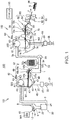
- FIG. 1 schematically illustrates the configuration of a sheet manufacturing apparatus 100 according to the invention.
- the sheet manufacturing apparatus 100 executes a recycling process of extracting fiber from a feedstock material MA containing fiber and making new sheets S from the fiber.
- the sheet manufacturing apparatus 100 can make multiple types of sheets S, and by mixing additives with the feedstock material MA according to the application of the sheets S, can adjust the paper strength and whiteness, or add color, scents, or functions such as fire retardancy to the sheets S.
- the sheet manufacturing apparatus 100 can also adjust the density, thickness, size, and shape of the sheets S.
- Typical examples of the sheets S include office paper in standard sizes such as A4 or A3, various kinds of sheet products such as cleaning sheets for cleaning flooring, sheets for cleaning up oil and grease, and sheets cleaning toilets, as well as paper plates and other products.
- the sheet manufacturing apparatus 100 is an example of a fibrous feedstock recycling device and a fiber processing device according to the invention.
- the sheet manufacturing apparatus 100 includes a feedstock feeder 10, shredder 12, defibrator 20, classifier 40, first web former 45, rotor 49, mixing device 50, air-laying device 60, second web former 70, conveyor 79, sheet former 80, and sheet cutter 90.
- the shredder 12, defibrator 20, classifier 40, and first web former 45 configure a defibration process unit 101 that defibrates the feedstock material MA and acquires material used to make the sheets S.
- the rotor 49, mixing device 50, air-laying device 60, second web former 70, sheet former 80, and sheet cutter 90 configure a sheet maker 102 that processes the material acquired by the defibration process unit 101 and makes sheets S.
- the feedstock feeder 10 in this example is an automatic sheet feeder that holds and continuously supplies the feedstock material MA to the shredder 12.
- the feedstock material MA may be a material containing fiber, such as recovered paper, waste paper, and pulp sheets.
- the shredder 12 has shredder blades 14 that cut the feedstock material MA supplied by the feedstock feeder 10, shreds the feedstock material MA in air by the shredder blades 14, and produces paper shreds a few centimeters square.
- the shape and size of the shreds is not specifically limited.
- a paper shredder for example, may be used as the shredder 12.
- the feedstock material MA shredded by the shredder 12 is then collected in a hopper 9, and conveyed through a conduit 2 to the defibrator 20.
- the defibrator 20 defibrates the coarse shreds produced by the shredder 12. Defibration is a process of breaking feedstock material MA containing bonded fibers into single fibers or a few intertwined fibers.
- the feedstock material MA may also be referred to as material to defibrate or defibration material.
- resin particles, ink, toner, bleeding inhibitors, and other materials included in the feedstock material MA can be expected to also separate from the fibers.
- the material that has passed through the defibrator 20 is referred to as defibrated material.
- the defibrated material may contain additives that are separated from the fiber during defibration, including resin, ink, toner, and other color additives, bleeding inhibitors, and paper strengthening agents.
- the resin particles contained in the defibrated material is resin that is mixed to bind fibers together when the feedstock material MA was manufactured.
- the shape of the fiber in the defibrated material may be as strings or ribbons.
- the fiber contained in the defibrated material may be as individual fibers not intertwined with other fibers, or as clumps, which are multiple fibers tangled with other defibrated material into clumps.
- the defibrator 20 is an example of a refiner.
- the defibrated material MB described below is an example of refined material.
- the defibrator 20 defibrates in a dry process.
- a dry process as used herein means that the defibration process is done in air instead of a wet solution.
- the defibrator 20 uses a defibrator such as an impeller mill in this example. More specifically, the defibrator 20 has a rotor (not shown in the figure), and a liner (not shown in the figure) positioned around the outside of the rotor, and the shreds go between the rotor and the liner and are defibrated.
- the shreds are conveyed by an air current from the shredder 12 to the defibrator 20.
- This air current may be generated by the defibrator 20, or the air current may be produced by a blower (not shown in the figure) disposed upstream or downstream from the defibrator 20 in the conveyance direction of the shreds and defibrated material.
- the defibrated material is carried by the air current from the defibrator 20 through a conduit 3 to the classifier 40.
- the air current conveying the defibrated material to the classifier 40 may be generated by the defibrator 20 or the air current from the blower described above may be used.
- the classifier 40 separates the components of the defibrated material defibrated by the defibrator 20 by the size of the fiber.
- the size of the fiber primarily indicates the length of the fiber.
- the classifier 40 has an inlet 42 through which defibrated material is introduced to the drum 41, and an exit 44 from which second screened material described below is discharged from the drum 41.
- the exit 44 connects to the defibrator 20 through a conduit 8, and the classifier 40 returns the second screened material through the conduit 8 to the defibrator 20.
- the first web former 45 forms a first web W1 by forming the material separated by the classifier 40 into a web.
- FIG. 2 shows the basic configuration of the classifier 40 and first web former 45, and shows the main parts thereof from the side.
- the classifier 40 includes a drum 41, and a housing 43 around the drum 41.
- the drum 41 in this example is configured with a sieve. More specifically, the drum 41 has mesh, a filter or a screen with openings that functions as a sieve. More specifically, the drum 41 is cylindrical, and is rotationally driven centered on the axis of the cylinder by a first sieve motor 40a (driver, sieve driver). At least part of the circumferential surface of the drum 41 is mesh.
- the mesh of the drum 41 may be a metal screen, expanded metal made by expanding a metal sheet with slits formed therein, or punched metal, for example.
- reference numeral 41a indicates the openings in the drum 41.
- the operating speed at which the drum 41 operates by driving the first sieve motor 40a is speed VB.
- This speed VB is also referred to as the rotational speed of the drum 41.
- the direction of rotation of the drum 41 is not limited to the direction shown in FIG. 2 , and the drum 41 may be driven in reverse, or driven bidirectionally by the first sieve motor 40a alternating the direction of rotation.
- speed VB is not limited to the speed in the direction indicated by the arrow in FIG. 2 , and may indicate the speed of the drum 41 relative to when the drum 41 is not turning.
- the drum 41 is an example of a sieve according to the invention.
- the defibrated material MB that is fed into the drum 41, and the first screened material MC that is sieved through the openings 41a, are examples of material.
- the first web former 45 includes a mesh belt 46, tension rollers 47, and a suction device 48.
- the mesh belt 46 is an endless metal belt, and is mounted around multiple tension rollers 47.
- the mesh belt 46 circulates in a path configured by the tension rollers 47. Part of the path of the mesh belt 46 is flat in the area below the drum 41, and the mesh belt 46 forms a flat surface.
- One of the tension rollers 47 is a drive roller 47a that drives the mesh belt 46.
- the drive roller 47a turns as driven by a first belt motor 47b, and drives the mesh belt 46 in the direction indicated by the arrow in the figure.
- the operating speed at which the mesh belt 46 operates by the drive power of the first belt motor 47b is speed VA.
- This speed VA is also referred to as the conveyance speed of the mesh belt 46.
- a servo motor, stepper motor, or other known type of motor may be used for the first sieve motor 40a and first belt motor 47b.
- Gears, links, or other transfer mechanisms that transfer power may also be disposed between the first sieve motor 40a and drum 41, and between the drive roller 47a and first belt motor 47b.
- the defibrated material MB introduced from the inlet 42 to the inside of the drum 41 is separated by rotation of the drum 41 into screened material that has passed through the openings 41a of the drum 41, and remnants that have not passed through the openings 41a.
- the screened material that has passed through the openings 41a includes fiber or particles that are smaller than the openings 41a, and is referred to below first screened material MC.
- the remnants include, for example, fibers, undefibrated shreds, and clumps that are larger than the openings 41a, and are referred to as second screened material below.
- the first screened material MC descends inside the housing 43 and falls onto the first web former 45. As described above, the second screened material is conveyed from the exit 44 through conduit 8 to the defibrator 20.
- the classifier 40 is an example of a separator.
- the first screened material MC that passes through the openings 41a descends inside the housing 43 to the mesh belt 46. Numerous openings are also formed in the mesh belt 46. Of the first screened material MC that descends from the drum 41, components that are larger than the openings in the mesh belt 46 accumulate on the mesh belt 46. Components of the first screened material MC that are smaller than the openings in the mesh belt 46 pass through the openings. The components that pass through the openings in the mesh belt 46 are referred to as third screened material D.
- the third screened material D contains fibers in the defibrated material that are shorter than the openings in the mesh belt 46, as well as resin particles, and particles of ink, toner, bleeding inhibitors and other material that is separated from the fibers by the defibrator 20.
- the mesh belt 46 in this example is an example of an accumulator according to the invention.
- the suction device 48 pulls air from below the mesh belt 46.
- the suction device 48 is connected through a conduit 23 to a first dust collector 27.
- the first dust collector 27 has a filter for separating the third screened material D from the air current. Downstream from the first dust collector 27 is a first collection blower 28, and the first collection blower 28 suctions air from the first dust collector 27.
- This configuration suctions small third screened material D from the first screened material MC that has descended to the mesh belt 46 by the suction of the first collection blower 28, and collects the third screened material D by the filter of the first dust collector 27.
- the air that passes through the filter of the first dust collector 27 is discharged from a conduit 29.
- the air current suctioned by the suction device 48 pulls the first screened material MC descending from the drum 41 to the mesh belt 46, the air current has the effect of promoting accumulation of the first screened material MC.
- the first screened material MC accumulated on the mesh belt 46 accumulates in a web, forming a first web W1.
- the first web W1 comprises mainly fibers that are larger than the openings in the mesh belt 46, and is a fluffy web containing much air.
- the first web W1 is conveyed by movement of the mesh belt 46 to the rotor 49.
- the rotor 49 has a base 49a connected to a driver such as a motor (not shown in the figure), and fins 49b protruding from the base 49a, and when the base 49a turns in direction of rotation R indicated by the arrow, the fins 49b rotate around the base 49a.
- the fins 49b in this example are flat blades.
- the rotor 49 is disposed at the end of the flat part of the path of the mesh belt 46. Because the path of the mesh belt 46 curves down at this end, the mesh belt 46 also curves and moves down. As a result, the first web W1 conveyed by the mesh belt 46 extends forward from the mesh belt 46 and contacts the rotor 49. The first web W1 is then broken up by the fins 49b striking the first web W1, and reduced to small clumps of fiber. These clumps then travel through the conduit 7 located below the rotor 49, and are conveyed to the mixing device 50. Because the first web W1 is a soft, fluffy structure of fiber accumulated on the mesh belt 46 as described above, the first web W1 is easily broken up by collision with the rotor 49.
- the rotor 49 is positioned so that the fins 49b can contact the first web W1 but the fins 49b do not touch the mesh belt 46.
- the distance between the fins 49b and the mesh belt 46 at the closest point is preferable greater than or equal to 0.05 mm and less than or equal to 0.5 mm.
- the mixing device 50 mixes the first screened material with an additive.
- the mixing device 50 has an additive supplier 52 that supplies an additive, a conduit 54 through which the first screened material MC and additive flow, and a mixing blower 56.
- One or more additive cartridges 52a storing additives are installed to the additive supplier 52.
- the additive cartridges 52a may be removably installed to the additive supplier 52.
- the additive supplier 52 includes an additive extractor 52b that extracts additive from the additive cartridges 52a, and an additive injector 52c that injects the additive extracted by the additive extractor 52b into the conduit 54.
- the additive extractor 52b has a feeder (not shown in the figure) that feeds additive in a powder or particulate form from inside the additive cartridges 52a, and removes additive from some or all of the additive cartridges 52a.
- the additive removed by the additive extractor 52b is conveyed to the additive injector 52c.
- the additive injector 52c holds the additive removed by the additive extractor 52b.
- the additive injector 52c has a shutter (not shown in the figure) that opens and closes the connection to the conduit 54, and when the shutter is open, the additive extracted by the additive extractor 52b is fed into the conduit 54.
- the additive supplied from the additive supplier 52 includes resin (binder) that binds multiple fibers together when heated.
- the resin contained in the additive melts when passing through the sheet former 80 and binds multiple fibers together.
- the resin may be a thermoplastic resin or thermoset resin, such as AS resin, ABS resin, polypropylene, polyethylene, polyvinyl chloride, polystyrene, acrylic resin, polyester resin, polyethylene terephthalate, polyethylene ether, polyphenylene ether, polybutylene terephthalate, nylon, polyimide, polycarbonate, polyacetal, polyphenylene sulfide, and polyether ether ketone. These resins may be used individually or in a desirable combination.
- the additive supplied from the additive supplier 52 may contain components other than resin for binding fibers.
- the additive also includes a coloring agent for coloring the fiber, an anti-blocking agent to prevent agglomeration of fibers and agglomeration of resin, or a flame retardant for making the fiber difficult to burn.
- the additive may also be in the form of fibers or particles.
- the mixing blower 56 produces an air current flowing through a conduit 54 connecting 7 to the air-laying device 60.
- the mixing blower 56 in this example can be configured with a motor (not shown in the figure), blades (not shown in the figure) that turn as driven by the motor, and a case (not shown in the figure) housing the blades, and may be a configuration in which the blades and case are connected.
- the mixing blower 56 may also include a mixer for mixing the first screened material and the additive. The mixture combined by the mixing device 50 is then conveyed by the air current produced by the mixing blower 56 to the air-laying device 60, and introduced through the inlet 62 to the air-laying device 60.
- the air-laying device 60 detangles and causes the fibers in the mixture to disperse in air while precipitating to the second web former 70. If the additive supplied from the additive supply device 52 is fibrous, these additive fibers are also detangled by the air-laying device 60 and descend to the second web former 70. The second web former 70 accumulates the mixture precipitating from the air-laying device 60, forming a second web W2.
- FIG. 3 shows the basic configuration of the air-laying device 60 and second web former 70, and shows the main parts thereof from the side.
- the air-laying device 60 includes a drum 61, and a housing 63 around the drum 61.
- the air-laying device 60 includes a drum 61, and a housing 63 that houses the drum 61.
- the drum 61 is a cylindrical construction with holes 61a in the drum 61 as shown in FIG. 3 .
- drum 61 in this example is configured with a sieve. More specifically, the drum 61 has mesh, a filter or a screen with openings that functions as a sieve. More specifically, the drum 61 is cylindrical, and is rotationally driven centered on the axis of the cylinder by second sieve motor 60a (driver, sieve driver). At least part of the circumferential surface of the drum 61 is mesh.
- the mesh of the drum 61 may be a metal screen, expanded metal made by expanding a metal sheet with slits formed therein, or punched metal, for example.
- the drum 61 turns as driven by the second sieve motor 60a, functions as a sieve, and the mixture detangled by rotation of the drum 61 passes through the holes 61a and descends.
- the mixture that passes through the inlet 62 is referred to as mixture MX below.
- the operating speed at which the drum 61 operates by driving the second sieve motor 60a is speed VD.
- This speed VD is also referred to as the rotational speed of the drum 61.
- the direction of rotation of the drum 61 is not limited to the direction shown in FIG. 3 , and the drum 61 may be driven in reverse, or driven bidirectionally by the second sieve motor 60a alternating the direction of rotation.
- speed VD is not limited to the speed in the direction indicated by the arrow in FIG. 3 , and may indicate the speed of the drum 61 relative to when the drum 61 is not turning.
- the second web former 70 is located below the drum 61.
- the second web former 70 in this example includes a mesh belt 72, tension rollers 74, and a suction mechanism 76.
- the mesh belt 72 is an endless metal belt similar to the mesh belt 46 described above, and is mounted around multiple tension rollers 74.
- the mesh belt 72 circulates in a path configured by the tension rollers 74. Part of the path of the mesh belt 72 is flat in the area below the drum 61, and the mesh belt 72 forms a flat surface. There are also many holes in the mesh belt 72.
- One of the tension rollers 74 is a drive roller 74a that drives the mesh belt 72.
- the drive roller 74a turns as driven by a second belt motor 74b, and drives the mesh belt 74 in the direction indicated by the arrow in the figure.
- the operating speed at which the mesh belt 74 operates by the drive power of the second belt motor 74b is speed VC.
- This speed VC is also referred to as the conveyance speed of the mesh belt 72.
- a servo motor, stepper motor, or other known type of motor may be used for the second sieve motor 60a and second belt motor 74b.
- Gears, links, or other transfer mechanisms that transfer power may also be disposed between the second sieve motor 60a and drum 61, and between the drive roller 74a and second belt motor 74b.
- the mixture MX inside the drum 61 passes through the holes 61a by rotation of the drum 61, and descends to the mesh belt 72.
- components larger than the holes in the mesh belt 72 accumulate on the mesh belt 72.
- Components of the mixture that are smaller than the holes in the mesh belt 72 pass through the holes.
- a suction mechanism 76 is connected to a conduit 66.
- the conduit 66 is connected through a second dust collector 67 to the second collection blower 68.
- the second dust collector 67 has a filter that collects particles and fiber that pass through the mesh belt 72.
- the second collection blower 68 is a blower that suctions air through the conduit 66, and discharges the suctioned air outside the sheet manufacturing apparatus 100 or to a specific place in the sheet manufacturing apparatus 100.
- the suction mechanism 76 pulls air from below the mesh belt 72 by the suction of the second collection blower 68, and collects particles and fiber contained in the suctioned air by the second dust collector 67.
- the air current suctioned by the second collection blower 68 pulls the mixture descending from the drum 61 to the mesh belt 72, and has the effect of promoting accumulation of the mixture on the mesh belt 72.
- the suctioned air current of the suction device 48 creates a down flow in the path of the mixture descending from the drum 61, and can be expected to have the effect of preventing the precipitating fibers from becoming tangled.
- the mixture MX accumulated on the support surface 71 is laid in a web on the flat part of the mesh belt 72, forming a second web W2.
- a wetting device 78 is disposed to the conveyance path of the mesh belt 72 downstream from the air-laying device 60.
- the wetting device 78 is a mist humidifier that produces and supplies a water mist to the mesh belt 72.
- the wetting device 78 in this example has a tank that holds water, and an ultrasonic vibrator that converts the water to mist. Because the moisture content of the second web W2 can be adjusted by the mist supplied by the wetting device 78, the mist can be expected to suppress accretion of fiber on the mesh belt 72 due to static electricity.
- the second web W2 is then conveyed by the conveyor 79, separates from the mesh belt 72, and is conveyed to the sheet former 80.
- the conveyor 79 in this example has a mesh belt 79a, rollers 79b, and a suction mechanism 79c.
- the suction mechanism 79c has a blower (not shown in the figure), and produces an air current upward through the mesh belt 79a by the suction of the blower.
- the second web W2 is separated from the mesh belt 72 and pulled to the mesh belt 79a by this air current.
- the mesh belt 79a moves by rotation of the rollers 79b, and conveys the second web W2 to the sheet former 80.
- the sheet former 80 binds fibers recovered from the first screened material and contained in the second web W2 through the resin contained in the additive.
- the sheet former 80 has a compression device 82 that compresses the second web W2, and a heating device 84 that heats the second web W2 after compression by the compression device 82.
- the compression device 82 comprises a pair of calender rolls 85.
- the compression device 82 has a hydraulic press mechanism (not shown in the figure) that applies nip pressure to the calender rolls 85, and a motor or other driver (not shown in the figure) that causes the calender rolls 85 to rotate in the direction of the heating device 84.
- the compression device 82 compresses and conveys the second web W2 to the heating device 84 with a specific nip pressure by the calender rolls 85.
- the heating device 84 includes a pair of heat rollers 86.
- the heating device 84 also has a heater (not shown in the figure) that heats the surface of the heat rollers 86 to a specific temperature, and a motor or other driver (not shown in the figure) that causes the heat rollers 86 to rotate in the direction of the sheet cutter 90.
- the heating device 84 holds and heats the second web W2 compressed to a high density by the compression device 82, and conveys the heated second web W2 to the sheet cutter 90.
- the second web W2 is heated in the heating device 84 to a temperature greater than the glass transition temperature of the resin contained in the second web W2, forming a sheet S.
- the sheet cutter 90 cuts the sheet S formed by the sheet former 80.
- the sheet cutter 90 has a first cutter 92 that cuts the sheet S crosswise to the conveyance direction of the sheet S indicated by the arrow F in the figure, and a second cutter 94 that cuts the sheet S parallel to the conveyance direction F.
- the sheet cutter 90 cuts the length and width of the sheet S to a specific size, forming single sheets.
- the single sheets S cut by the sheet cutter 90 are then stored in the discharge tray 96.
- the discharge tray 96 may be a tray or stacker for holding the manufactured sheets, and the sheets S discharged to the tray can be removed and used by the user.
- the defibration process unit 101 includes at least the defibrator 20, and may include the classifier 40 and first web former 45.
- the defibration process unit 101 makes defibrated material from feedstock material MA, or forms the defibrated material into a web configuration to make a first web W1.
- the work product of the defibration process unit 101 may be conveyed through the rotor 49 to the mixing device 50, or removed from the sheet manufacturing apparatus 100 without passing through the rotor 49 and stored. This work product can also be sealed in specific packages in a form ready for shipping or sale.
- the sheet maker 102 is a functional device for making the work product manufactured by the defibration process unit 101 into sheets S, and may be referred to as a processor.
- the sheet maker 102 includes the mixing device 50, air-laying device 60, second web former 70, conveyor 79, sheet former 80 and sheet cutter 90, and may also include the rotor 49.
- the sheet maker 102 may also include the additive supply device 52.
- the sheet manufacturing apparatus 100 may be configured with the defibration process unit 101 and sheet maker 102 as a single integrated system, or with the defibration process unit 101 and sheet maker 102 separate.
- the defibration process unit 101 is an example of a fibrous feedstock recycling device according to the invention.
- the sheet maker 102 is an example of a sheet forming device that processes defibrated material into sheets. Each of these components may also be conceived of as processing devices.
- the forming conditions of the first web W1 formed by the first web former 45 are described below with reference to FIG. 2 .
- the thickness of the first web W1 is determined by the amount of first screened material MC, which is the material supplied to the mesh belt 46, and the amount of movement of the mesh belt 46 per unit time.
- the amount of movement of the mesh belt 46 per unit time is speed VA shown in the figure.
- One factor determining the amount of first screened material MC supplied to the mesh belt 46 is the speed VB of the drum 41.
- speed VB increases, the defibrated material MB is more quickly defibrated in the drum 41, and the first screened material MC passes more easily through the openings 41a.
- speed VB increases, the greater the speed VB, the more easily the first screened material MC passes the openings 41a. Therefore, the amount of first screened material MC passing the openings 41a increases as the speed VB increases.
- the amount of first screened material MC passing the openings 41a changes when the drum 41 starts moving from a stop. Because rotation of the drum 41 produces friction between the fibers of the first screened material MC inside the drum 41, the first screened material MC also becomes charged. If the first screened material MC agglomerates due to this static electricity, it becomes more difficult for the first screened material MC to pass the openings 41a. On the other hand, when the drum 41 is stopped, the charge of the charged first screened material MC is discharged, and clumps of fiber in the first screened material MC break apart. Therefore, when the drum 41 starts turning from a stop, that is, when the drum 41 starts operating, the first screened material MC passes easily through the openings 41a. The amount of first screened material MC passing the openings 41a therefore temporarily increases at this time.
- the amount of first screened material MC passing the openings 41a is also affected by the humidity in the drum 41.
- Humidity as used here can be referred to as relative humidity (RH). If the humidity inside the drum 41 is high, charging of the fibers in the first screened material MC is alleviated, fiber agglomeration is suppressed, and the volume of fiber clumps to be broken up is low. Therefore, the higher the humidity inside the drum 41, the less variation there is in the amount of first screened material MC passing the openings 41a.
- the amount of first screened material MC passing the openings 41a also varies according to the length of the fiber in the first screened material MC. Short fibers pass through the openings 41a easily. Therefore, the shorter the fibers in the first screened material MC, the greater the amount of first screened material MC that passes the openings 41a.
- the greatest factor determining the amount of first screened material MC supplied from the drum 41 to the mesh belt 46 is therefore the speed VB of the drum 41.
- Factors that change the amount of first screened material MC include whether or not the drum 41 is starting up, the humidity inside the drum 41, and the length of fiber in the first screened material MC.
- the amount of material supplied to processes downstream from the first web former 45 may vary, affecting the quality of the sheets S manufactured by the sheet manufacturing apparatus 100.
- the controller 150 of the sheet manufacturing apparatus 100 therefore executes a control process that suppresses variation in the thickness of the first web W1.
- the sheet manufacturing apparatus 100 has a first belt speed detector 322 ( FIG. 4 ) for detecting the speed VA, and a first sieve speed detector 321 ( FIG. 4 ) for detecting speed VB.
- the sheet manufacturing apparatus 100 can also detect the humidity inside the drum 41.
- the sheet manufacturing apparatus 100 has a first temperature/humidity detector 323 (humidity detector).
- the first temperature/humidity detector 323 can be configured by a sensor unit having a temperature sensor and a humidity sensor.
- the temperature sensor may be a thermistor, resistance temperature detector, thermocouple, or IC temperature sensor, for example.
- the humidity sensor may be any configuration capable of detecting relative humidity, such as a resistance humidity sensor or a capacitance humidity sensor.
- the first temperature/humidity detector 323 detects the temperature and the relative humidity of the space inside the drum 41.
- the first temperature/humidity detector 323 may output the temperature and humidity detection values as an analog signal or as digital data indicating the detected values.
- the detected temperature and detected humidity may also be output as a combined value.
- the sheet manufacturing apparatus 100 also has a first thickness detector 324.
- the first thickness detector 324 is a sensor that detects the thickness of the first web W1.
- the first thickness detector 324 may be an optical thickness sensor that has a light source and a photosensor, emits light to the first web W1, and detects the amount of light passing the first web W1 to detect the thickness of the first web W1.
- the first thickness detector 324 may also be a contact thickness sensor having a probe that contacts the first web W1, and an encoder that detects the position of the probe, and detects the distance between the surface of the first web W1 and the surface of the mesh belt 46.
- the first thickness detector 324 may also be an ultrasonic thickness sensor, or a sensor that detects thickness by another method.
- the controller 110 may also control adjusting the thickness of the first web W1 based on the output of the first thickness detector 324. For example, if the thickness detected by the first thickness detector 324 is outside a predetermined range, the controller 110 may stop the sheet manufacturing apparatus 100 or issue a warning.
- the sheet manufacturing apparatus 100 may also have a second temperature/humidity detector 333 as a configuration for detecting the humidity inside the drum 61.
- the second temperature/humidity detector 333 can be configured by a sensor unit having a temperature sensor and a humidity sensor.
- the temperature sensor may be a thermistor, resistance temperature detector, thermocouple, or IC temperature sensor, for example.
- the humidity sensor may be any configuration capable of detecting relative humidity, such as a resistance humidity sensor or a capacitance humidity sensor.
- the second temperature/humidity detector 333 detects the temperature and the relative humidity of the space inside the drum 61.
- the second temperature/humidity detector 333 may output the temperature and humidity detection values as an analog signal or as digital data indicating the detected values.
- the detected temperature and detected humidity may also be output as a combined value.
- the sheet manufacturing apparatus 100 also has a second thickness detector 334.
- the second thickness detector 334 is a sensor that detects the thickness of the second web W2.
- the second thickness detector 334 may be an optical thickness sensor that has a light source and a photosensor, emits light to the second web W2, and detects the amount of light passing the second web W2 to detect the thickness of the second web W2.
- the second thickness detector 334 may also be a contact thickness sensor having a probe that contacts the second web W2, and an encoder that detects the position of the probe, and detects the distance between the surface of the second web W2 and the surface of the mesh belt 72.
- the second thickness detector 334 may also be an ultrasonic thickness sensor, or a sensor that detects thickness by another method.
- the controller 110 may also control adjusting the thickness of the second web W2 based on the output of the second thickness detector 334. For example, if the thickness detected by the second thickness detector 334 is outside a predetermined range, the controller 110 may stop the sheet manufacturing apparatus 100 or issue a warning.
- FIG. 4 is a block diagram of the control system of the sheet manufacturing apparatus 100.
- the sheet manufacturing apparatus 100 has a controller 110 that has a main processor 111 configured to control parts of the sheet manufacturing apparatus 100.
- the controller 110 has a main processor 111, ROM (Read Only Memory) 112, and RAM (Random Access Memory) 113.
- the main processor 111 is embodied by a processor such as a CPU (central processing unit), and controls parts of the sheet manufacturing apparatus 100 by running a basic control program stored in ROM 112.
- the main processor 111 may also be configured as a system chip including ROM 112, RAM 113, or other peripheral circuits, or other IP cores.
- ROM 112 nonvolatilely stores programs executed by the main processor 111.
- RAM 113 provides working memory used by the main processor 111, and temporarily stores programs the main processor 111 runs and data that is processed.
- Nonvolatile storage 120 stores programs the main processor 111 executes, and data the main processor 111 processes.
- the display panel 116 is an LCD or other type of display panel, and in this example is disposed externally to the sheet manufacturing apparatus 100.
- the display panel 116 displays the operating status of the sheet manufacturing apparatus 100, various settings, and warnings, for example.
- the touch sensor 117 detects user operations by touch or pressure.
- the touch sensor 117 is disposed over the display surface of the display panel 116, and detects operations on the display panel 116.
- the touch sensor 117 outputs to the main processor 111 operating data including the operating position and the number of operating positions.
- the main processor 111 Based on output from the touch sensor 117, the main processor 111 detects operation of the display panel 116, and acquires the operating positions.
- the main processor 111 enables GUI (graphical user interface) operations based on the operating position detected by the touch sensor 117, and the display data that was displayed on the display panel 116 when the operation was detected.
- GUI graphical user interface
- the controller 110 is connected through a sensor interface 114 to sensors disposed to parts of the sheet manufacturing apparatus 100.
- the sensor interface 114 is an interface that acquires detection values output by the sensors, and inputs to the main processor 111.
- the sensor interface 114 may include an A/D converter that converts analog signals output by the sensors to digital data.
- the sensor interface 114 may also supply drive current to the sensors.
- the sensor interface 114 may also include circuits that acquire sensor output values according to the sampling frequency controlled by the main processor 111, and output to the main processor 111.
- the sensor interface 114 is also connected to a feedstock sensor 301, and a paper discharge sensor 302, for example. Also connected to the sensor interface 114 are the first sieve speed detector 321, first belt speed detector 322, first temperature/humidity detector 323, and first thickness detector 324. Additionally, the second sieve speed detector 331, second belt speed detector 332, second temperature/humidity detector 333, and second thickness detector 334 are connected to the sensor interface 114.
- the first sieve speed detector 321 detects speed VB.
- the first sieve speed detector 321 may be configured with a rotary encoder and a sensor that contacts the rotary shaft or surface of the drum 41, and detects the rotational speed.
- the first sieve speed detector 321 may also be a circuit disposed inside the first sieve motor 40a, or configured as part of the first sieve motor 40a, that outputs a signal indicating the number of revolutions or the rotational speed of the first sieve motor 40a.
- the controller 110 may also function as the first sieve speed detector 321, and calculate the rotational speed of the first sieve motor 40a based on the drive current of the first sieve motor 40a.
- the second sieve speed detector 331 detects speed VD, which is the operating speed of the drum 61.
- the second sieve speed detector 331 may be configured identically to the first sieve speed detector 321.
- the first belt speed detector 322 detects speed VA, which is the operating speed of the mesh belt 46.
- the first belt speed detector 322 detects the speed of mesh belt 46 movement, the rotational speed of the tension rollers 74, or the rotational speed of the first belt motor 47b.
- the first belt speed detector 322 may be configured with a speed sensor or rotary encoder.
- the first belt speed detector 322 may also be a circuit disposed inside the first belt motor 47b, or configured as part of the first belt motor 47b, that outputs a signal indicating the number of revolutions or the rotational speed of the first belt motor 47b.
- the controller 110 may also function as the first belt speed detector 322, and calculate the rotational speed of the first belt motor 47b based on the drive current of the first belt motor 47b.
- the second belt speed detector 332 detects speed VC, which is the operating speed of the mesh belt 72.
- the second belt speed detector 332 may be configured identically to the second sieve speed detector 331.
- the feedstock sensor 301 detects the remaining amount of feedstock MA in the feedstock feeder 10.
- the paper discharge sensor 302 detects how many sheets S are stored in the tray or stacker of the tray 96.
- the controller 110 is connected to the drivers of the sheet manufacturing apparatus 100 through a driver interface 115.
- the drivers of the sheet manufacturing apparatus 100 include motors, pumps, and heaters, for example.
- the driver interface 115 may be a configuration directly connected to a motor, or connected to a drive circuit or drive chip (IC chip) that supplies drive current to a motor.
- a shredder 311, defibrator 312, additive supplier 313, blower 314, humidifier 315, drum driver 316, separator 317, and sheet cutter 318 are connected to the driver interface 115 as control objects of the controller 110.
- the shredder 311 in this example includes a motor or other drive device for turning the shredder blades 14.
- the defibrator 312 includes a motor or other drive device for turning the rotor (not shown in the figure) of the defibrator 20.
- the additive supplier 313 includes drivers such as a motor that drives a screw feeder for out-feeding additive, and a motor or actuator that opens and closes the shutters.
- the blowers 314 include the first collection blower 28, mixing blower 56, and second collection blower 68. These blowers may individually connect to the driver interface 115.
- the humidifier 315 includes the ultrasonic vibration generator (not shown in the figure) of the wetting device 78, a fan (not shown in the figure), and a pump (not shown in the figure).
- the drum driver 316 includes drivers such as a motor for turning drum 41, and a motor for turning drum 61.
- the separator 317 includes a driver such as a motor (not shown in the figure) for turning the rotor 49.
- the sheet cutter 318 includes motors (not shown in the figure) for respectively operating the blades of the first cutter 92 and second cutter 94 of the sheet cutter 90.
- a motor for driving the calender rolls 85, and a heater for heating the heat rollers 86, may also be connected to the driver interface 115.
- a first sieve motor 40a, first belt motor 47b, second sieve motor 60a, and second belt motor 74b are also connected to the driver interface 115.
- the controller 110 can control these motors to start turning and stop turning.
- the controller 110 can also control the speed of the first sieve motor 40a and first belt motor 47b.
- FIG. 5 is a function block diagram of the controller 110.
- the controller 110 embodies various function units by the cooperation of hardware and software resulting from a main processor 111 running a program.
- FIG. 5 shows the functions of the main processor 111 embodying these function units as controller 150.
- the controller 110 also configures storage 160, which is a logical storage device, using the memory area of the nonvolatile storage 120.
- the storage 160 may be configured using memory areas in ROM 112 and RAM 113.
- the controller 150 has a detection controller 151 and a drive controller 152. These controllers are embodied by the main processor 111 running a program.
- the controller 110 may also execute an operating system (OS) as a basic control program for controlling the sheet manufacturing apparatus 100 and configuring a platform for running application programs.
- OS operating system
- the function units of the controller 150 may be embodied as application programs.
- detectors controlled by the controller 150 include the first sieve speed detector 321, first belt speed detector 322, first temperature/humidity detector 323, and first thickness detector 324.
- a second sieve speed detector 331, second belt speed detector 332, second temperature/humidity detector 333, and second thickness detector 334 are also shown. These sensors are collectively referred to as sensors 300.
- FIG. 5 also shows the first sieve motor 40a, first belt motor 47b, second sieve motor 60a, and second belt motor 74b as drivers controlled by the controller 150. These other drivers are collectively referred to as driver 310.
- the storage 160 stores data processed by the controller 150.
- the storage 160 more specifically stores settings data 161, reference data 162, and speed setting data 163.
- the settings data 161 is generated by operating the touch sensor 117, or based on commands and data input through a communication interface (not shown in the figure) of the controller 110, and stored in storage 160.
- the settings data 161 include various settings related to operation of the sheet manufacturing apparatus 100.
- the settings data 161 may include the number of sheets S manufactured by the sheet manufacturing apparatus 100, the type and color of sheets S, operating conditions for parts of the sheet manufacturing apparatus 100, and other settings.
- the settings data 161 also includes a setting input through the touch sensor 117 related to the length of fiber in the feedstock material MA the sheet manufacturing apparatus 100 processes.
- the feedstock material MA is sheets S that were manufactured by the sheet manufacturing apparatus 100 and contain fiber that has been processed multiple times by the sheet manufacturing apparatus 100, and when the feedstock material MA contains fiber sourced from deciduous trees, the feedstock material MA contains short fibers.
- the settings data 161 may include values for input items related to the length of fiber in the feedstock material MA, such as the type of feedstock material MA, as data related to the length of fiber in the feedstock material MA.
- the reference data 162 includes reference values for evaluating the operating conditions for making sheets S in the sheet manufacturing apparatus 100. More specifically, the reference data 162 includes a reference value for determining whether the humidity detected by the first temperature/humidity detector 323 is high or low.
- the reference data 162 may also include reference values for evaluations related to the speed detected by the first sieve speed detector 321, first belt speed detector 322, second sieve speed detector 331, and second belt speed detector 332.
- the reference data 162 may also include standards for evaluating the detection values output from the first thickness detector 324 and second thickness detector 334.
- the reference values included in the reference data 162 may be a single value, or range values including maximum and minimum values for a range.
- the speed setting data 163 includes data for the controller 150 to control the speed of the first sieve motor 40a.
- the controller 150 starts the operation of the sheet manufacturing apparatus 100 manufacturing a sheet S from a stopped state, that is, causes the first sieve motor 40a to accelerate when operation starts to operate the drum 41 at a speed suitable for making a sheet S.
- the controller 150 increases speed VB from speed 0.
- the speed setting data 163 includes data related to speed when accelerating the drum 41 from a stopped state to speed VB.
- the speed setting data 163 includes data related to speed conditions defining the correlation between the time for accelerating the drum 41 from speed 0 and speed VB.
- the speed conditions may be conditions defining the change in speed, which may be referred to as the speed pattern.
- the detection controller 151 controls detected by the sensors 300, and acquires the detection values from the sensors.
- the detection controller 151 also acquires the detection values from the first sieve speed detector 321, first belt speed detector 322, first temperature/humidity detector 323, and first thickness detector 324.
- the detection controller 151 also acquires the detection values from the second sieve speed detector 331, second belt speed detector 332, second temperature/humidity detector 333, and second thickness detector 334.
- the drive controller 152 By controlling the driver 310 based on the detection values of the sensors 300 acquired by the detection controller 151, the drive controller 152 operates parts of the sheet manufacturing apparatus 100 according to the values in the settings data 161, and manufactures a sheet S.
- the drive controller 152 drives the first sieve motor 40a, first belt motor 47b, second sieve motor 60a, and second belt motor 74b. Based on the detection values of the first sieve speed detector 321 and first belt speed detector 322 acquired by the detection controller 151, the drive controller 152 controls the speed of the first sieve motor 40a and first belt motor 47b. As a result, speed VA and speed VB are adjusted to the set speeds.
- the drive controller 152 controls the speed of the second sieve motor 60a and second belt motor 74b. As a result, speed VC and speed VD are adjusted to the set speeds.
- the drive controller 152 sets the speed conditions of the first sieve motor 40a for starting the drum 41 from the stopped state.
- the speed conditions are data defining the rate of increase when accelerating the first sieve motor 40a from a full stop.
- the drive controller 152 sets the speed conditions based on the detection values of the first temperature/humidity detector 323 acquired by the detection controller 151, the settings data 161, reference data 162, and speed setting data 163.
- FIG. 6 and FIG. 7 are flow charts of the operation of the sheet manufacturing apparatus 100, and describe the operation of starting the sheet manufacturing apparatus 100 from when the sheet manufacturing apparatus 100 is stopped.
- the operation shown in FIG. 6 and FIG. 7 is executed by the drive controller 152 of the controller 150.
- the controller 150 first executes a setup process related to first sieve motor 40a operation (step ST1).
- the setup process of step ST1 is a process of making settings related to the speed of the first sieve motor 40a when the first sieve motor 40a starts operating. This setup process is described below with reference to FIG. 7 .
- the startup sequence is a sequence of operations sequentially starting parts of the sheet manufacturing apparatus 100 from the stopped state of the sheet manufacturing apparatus 100. More specifically, the startup sequence starts the shredder 12, defibrator 20, classifier 40, first web former 45, rotor 49, mixing device 50, air-laying device 60, second web former 70, sheet former 80, and sheet cutter 90 from the stopped state.
- the controller 150 controls the humidifier 315 to start operation of the wetting device 78 (step ST3). If the sheet manufacturing apparatus 100 has devices other than the wetting device 78 that add humidity, the controller 150 also starts those devices in step ST3.
- the controller 150 starts the blower 314 (step ST4), and starts the defibrator 312 and thereby starts the defibrator 20 turning (step ST5).
- the defibrator 20 then accelerates to a previously set speed, and thereafter operates at a constant speed.
- step ST6 the controller 150 starts the shredder 311 (step ST6). After step ST6, feedstock containing fiber is supplied to the shredder 311.
- the controller 150 also starts the first sieve motor 40a and first belt motor 47b, and starts driving the drum 41 and mesh belt 46 of the classifier 40 (step ST7).
- step ST7 the first sieve motor 40a is started and the speed of the first sieve motor 40a increases according to the conditions set in step ST1.
- the controller 150 starts the second sieve motor 60a and second belt motor 74b, and starts the drum 61 and mesh belt 72 (step ST8).
- the controller 150 then starts operation of the calender rolls 85 and heat rollers 86 of the sheet former 80 (step ST9), and completes the startup sequence.
- FIG. 7 is a flow chart of the setup process executes in step ST1 in FIG. 6 .
- the controller 150 first determines if there is defibrated material MB inside the drum 41 (step ST21). Whether or not there is any defibrated material MB may be determined based on input from the touch sensor 117, for example.
- step ST21 If there is no defibrated material MB inside the drum 41 (step ST21: NO), the controller 150 sets a first speed condition as the condition for accelerating the speed of the first sieve motor 40a (step ST22), and ends the setup process.
- step ST21 If there is defibrated material MB inside the drum 41 (step ST21: YES), the controller 150 determines whether or not the humidity detected by the first temperature/humidity detector 323 is greater than or equal to the reference value contained in the reference data 162 (step ST23). If the humidity is greater than or equal to the reference value (step ST23: YES), the controller 150 determines if the length of fiber contained in the defibrated material MB is greater than or equal to the reference value contained in the reference data 162 (step ST24).
- step ST24 If the length of fiber contained in the defibrated material MB is greater than or equal to the reference value contained in the reference data 162 (step ST24: YES), the controller 150 sets a second speed condition as the condition for accelerating the speed of the first sieve motor 40a (step ST25), and ends the setup process.
- step ST24 If the length of fiber contained in the defibrated material MB is shorter than the reference value (step ST24: NO), the controller 150 sets a third speed condition as the condition for accelerating the speed of the first sieve motor 40a (step ST26), and ends the setup process.
- step ST23 determines if the humidity is less than the reference value (step ST23: NO). If the humidity is less than the reference value (step ST23: NO), the controller 150 determines if the length of fiber contained in the defibrated material MB is greater than or equal to the reference value contained in the reference data 162 (step ST27).
- step ST27: YES If the length of fiber contained in the defibrated material MB is greater than or equal to the reference value (step ST27: YES), the controller 150 sets a fourth speed condition as the condition for accelerating the speed of the first sieve motor 40a (step ST28), and ends the setup process. If the length of fiber contained in the defibrated material MB is shorter than the reference value (step ST27: NO), the controller 150 sets a fifth speed condition as the condition for accelerating the speed of the first sieve motor 40a (step ST28), and ends the setup process.
- the first to fifth speed conditions are basic conditions for accelerating from zero to speed VB when starting the drum 41, and include a target speed for the first sieve motor 40a, and either the time for acceleration to the target speed or the acceleration rate of the first sieve motor 40a.
- FIG. 8 is a graph showing an example of the operating speed VB of the drum 41 and change in thickness of the first web W1.
- This speed VB is the value detected by the first sieve speed detector 321
- the thickness of the first web W1 is the value detected by the first thickness detector 324.
- (1) indicates speed VB
- (2) indicates the thickness of the first web W1.
- (2) indicates the value detected by the first thickness detector 324 when speed VB changes as indicated by the (1).
- the Y-axis indicates speed VB and thickness of the first web W1
- coordinate 0 on the Y-axis indicates speed 0 (stopped) and the first web W1 thickness 0.
- the X-axis indicates time, and coordinate 0 indicates the beginning of the startup sequence. After the startup sequence starts, the time at which the first sieve motor 40a starts turning is time T1.
- the target value set for the thickness of the first web W1 is thickness TH1.
- the thickness of the first web W1 is ideally held constant at thickness TH1.
- the thickness TH1 may be set to a value in the range 2 mm to 10 mm in this example, but may be set thicker or thinner.
- FIG. 8 is an example of the controller 150 controlling the first sieve motor 40a according to the first speed condition, and the value detected by the first thickness detector 324 is indicated by the (2).
- the target speed for speed VB is set to speed V1.
- This target speed V1 is an example of a first speed of the invention.
- the target speed V1 may be set to a value in the range 50 rpm - 1000 rpm, for example, but may be slower or faster.
- acceleration time the time required for speed VB to accelerate to target speed V1 is referred to as the acceleration time.
- the first speed condition is the condition enabling speed VB to reach target speed V1 by time T2.
- the acceleration time is period TE1 from time T1 to time T2.
- Period TE1 is set in this example to a range from 1 second to 10 seconds, but may be shorter or longer.
- the amount of first screened material MC falling from the drum 41 is temporarily greater than when defibrated material MB is not in the drum 41.
- the amount of first screened material MC dropping to the mesh belt 46 after the first sieve motor 40a starts turning is temporarily greater than the amount suitable for making a sheet S.
- the thickness of the first web W1 exceeds thickness TH1, and the peak thickness TH2 is significantly greater than thickness TH1.
- the controller 150 sets one of the second to fifth speed conditions when defibrated material MB is already inside the drum 41.
- the second to fifth speed conditions each set the speed VB to a slower speed than target speed V1 for a specific time. In other words, the acceleration time is longer than period TE1.
- the second speed condition is a condition whereby the acceleration time is adjusted to a period longer than period TE1. As a result, the time at which speed VB reaches the target speed V1 under the second speed condition is delayed from time T2.
- the fourth speed condition defibrated material MB is in the drum 41, the humidity detected by the first temperature/humidity detector 323 is lower than to the reference value, and the fiber length is greater than or equal to the reference value. Because the humidity inside the drum 41 is lower than when the second speed condition is set, the amount of first screened material MC falling from the drum 41 increases temporarily.
- the fourth speed condition is a condition whereby the acceleration time is adjusted to a period longer than in the second speed condition. As a result, the time at which speed VB reaches the target speed V1 under the fourth speed condition is later than the time under the second speed condition.
- the third speed condition In the third speed condition, defibrated material MB is in the drum 41, the humidity detected by the first temperature/humidity detector 323 is greater than or equal to the reference value, and the fiber length is shorter than the reference value. Because the fiber length is shorter than when the second speed condition is set, the amount of first screened material MC falling from the drum 41 increases temporarily.
- the third speed condition is a condition whereby the acceleration time is adjusted to a period longer than in the second speed condition. As a result, the time at which speed VB reaches the target speed V1 under the third speed condition is later than the time under the second speed condition.
- the time required for the speed VB to reach the target speed V1 under the third speed condition and the fourth speed condition may be the same or different.
- the length of the acceleration time is determined with consideration for whether the effect of humidity inside the drum 41 on the amount of first screened material MC that drops from the drum 41, or the effect of the length of fiber in the defibrated material MB on the amount of first screened material MC that drops from the drum 41, is greater.
- the acceleration time of the fourth speed condition is preferably set longer than the acceleration time of the third speed condition.
- the acceleration time of the third speed condition is preferably set longer than the acceleration time of the fourth speed condition.
- the humidity detected by the first temperature/humidity detector 323 is lower than the reference value, and the length of fiber is shorter than the reference value.
- the acceleration time is longer than the first to fourth speed conditions.
- the time required for speed VB to reach the target speed V1 in the fifth speed condition is longer than in the first to fourth speed conditions.
- the controller 150 suppresses variation in the thickness of the first web W1 by varying the acceleration of the first sieve motor 40a during startup when the amount of first screened material MC dropping from the drum 41 to the mesh belt 46 increases temporarily.
- the controller 150 also suppresses variation in the thickness of the first web W1 by varying the acceleration of the drum 41 during startup of the drum 41 (in other words, during startup of the first sieve motor 40a) according to the humidity detected by the first temperature/humidity detector 323 and the fiber length of the defibrated material.
- the amount of first screened material MC supplied to processes downstream from the first web former 45 can be stabilized, and variation in the quality of the sheet S can be suppressed.
- the burden of making manual adjustments to suppress variation in the quality of the sheet S can also be reduced.
- FIG. 9 , FIG. 10 , FIG. 11 , and FIG. 12 are graphs showing an example of the operating speed VB of the drum 41 and thickness of the first web W1 when the second to fifth speed conditions are set.
- (1 ) indicates speed VB detected by the first sieve speed detector 321, and (2) indicates the thickness of the first web W1 detected by the first thickness detector 324.
- the Y-axis, X-axis, target speed V1, thickness TH1 and TH2, and time T1 are the same as in FIG. 8 .
- these figures also show time T2 from FIG. 8 .
- FIG. 9 shows an example in which the speed VB changes in steps, and more specifically an example in which speed VB changes in two steps.
- the controller 150 sets a period for holding an intermediate speed V2 that is lower than the target speed V1 before starting accelerating speed VB to target speed V1. More specifically, the controller 150 starts turning the first sieve motor 40a at time T1, and accelerates the first sieve motor 40a so that speed VB reaches intermediate speed V2 at time T3. The controller 150 then holds speed VB at intermediate speed V2 until time T4, then accelerates the first sieve motor 40a again from time T4 to reach target speed V1 at time T5.
- the time T5 at which speed VB reaches target speed V1 is after time T2 described above.
- the controller 150 holds speed VB at a speed less than target speed V1 (intermediate speed V2) for the period from time T1 to time T5 after the first sieve motor 40a starts turning.
- the value detected by the first thickness detector 324 fluctuates from approximately time T2, but the peak thickness TH3 of the first web W1 is less than the peak thickness TH2 shown in FIG. 8 . This demonstrates that variation in the thickness of the first web W1 is suppressed.
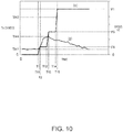
- FIG. 10 shows an example in which the speed VB changes in steps, and more specifically an example in which speed VB changes in three steps.
- the controller 150 sets a period for holding an intermediate speed V4 and an intermediate speed V5 that are lower than the target speed V1 before starting accelerating speed VB to target speed V1. More specifically, the controller 150 starts turning the first sieve motor 40a at time T1, and accelerates the first sieve motor 40a so that speed VB reaches intermediate speed V4 at time T11. The controller 150 then holds speed VB at intermediate speed V4 until time T12, then accelerates the first sieve motor 40a again from time T12 to reach intermediate speed V5 at time T13. The controller 150 then holds speed VB at intermediate speed V5 until time T14, then accelerates the first sieve motor 40a again from time T14 to reach target speed V1 at time T15.
- the time T15 at which speed VB reaches target speed V1 is after time T2 described above.
- the controller 150 holds speed VB at a speed less than target speed V1 (intermediate speed V2) for the period from time T1 to time T15 after the first sieve motor 40a starts turning.
- the value detected by the first thickness detector 324 fluctuates from approximately time T11, but the peak thickness TH4 of the first web W1 is less than the peak thickness TH2 shown in FIG. 8 . More specifically, the peak thickness TH4 is successfully suppressed by inserting a period (time T1 to time T12) of rotation at an intermediate speed V4 that is significantly slower than the target speed V1 immediately after the drum 41 starts turning when the amount of first screened material MC passing through the drum 41 easily increases.
- the controller 150 can change the speed VB in steps, and the number of steps in the speed VB, and the intermediate speeds, can be varied.
- speed VB may be changed in four or more steps.
- FIG. 11 shows an example of linear change in the speed VB.
- the controller 150 linearly increases speed VB from speed 0 to target speed V1 with time T21 at which the speed VB reaches target speed V1 being later than time T2.
- the acceleration time in this example is longer than period TE1 ( FIG. 8 ).
- the peak thickness TH5 of the first web W1 is less than the peak thickness TH2 shown in FIG. 8 , and variation in the thickness of the first web W1 is successfully suppressed.
- control of the first sieve motor 40a by the controller 150 is simple.
- this is an example of in which managing the data for controlling the first sieve motor 40a is simple, and setting and adjusting the conditions is easy.
- FIG. 12 shows an example of changing speed VB nonlinearly.
- the controller 150 controls the first sieve motor 40a to change the rate of acceleration while speed VB accelerates from speed 0 to target speed V1 so that speed VB reaches target speed V1 at time T31.
- this example includes a first operation in which acceleration is slow immediately after rotation starts at time T1 and acceleration then increases over time, and a second operation in which the rate of acceleration then decreases as the speed VB approaches target speed V1.
- the acceleration time is also longer than period TE1 ( FIG. 8 ). Furthermore, because the change in acceleration, which is the rate of change in speed VB, is smooth, variation in the force applied to the defibrated material MB inside the drum 41 is suppressed. As a result, an effect of suppressing variation in the amount of first screened material MC falling from the drum 41 can be expected. As indicated by the line (2) in FIG. 12 , the peak thickness TH6 in the first web W1 is less than the peak thickness TH2 shown in FIG. 8 , and variation in the thickness of the first web W1 is successfully suppressed.
- the second to fifth speed conditions can use the examples shown in FIG. 9 to FIG. 12 .
- all of the second to fifth speed conditions can use the two step acceleration pattern shown in FIG. 9 .
- the second to fifth speed conditions are set so that the time T5 at which speed VB reaches target speed V1 differs.
- the second to fifth speed conditions may include patterns that change the speed VB as shown in FIG. 9 .
- the pattern of change in speed VB may also be the same in the second to fifth speed conditions.
- the second to fifth speed conditions may be conditions that change speed VB by one or more of the different patterns shown in FIG. 9 to FIG. 12 .
- speed VB is held constant after reach target speed V1, but speed VB does not need to remain constant at target speed V1 throughout sheet S production.
- speed VB may be varied according to the sheet S manufacturing conditions and the sheet manufacturing apparatus 100 operating conditions.
- Control based on the detected humidity may also set an intermediate speed V2 lower than the target speed V1 based on the humidity detected when the defibration process unit 101 is stopped, and the humidity detected after the defibration process unit 101 starts running.
- a sheet manufacturing apparatus 100 has a drum 41 that sieves first screened material MC, which is material containing fiber, and a mesh belt 46 that accumulates first screened material MC discharged from the drum 41.
- the sheet manufacturing apparatus 100 also has a sheet maker 102 as a processor that processes the first screened material MC accumulated on the mesh belt 46. While making a sheet S, that is, during processing, the drum 41 operates at a target speed V1, and when starting from when the drum 41 is stopped, a startup operation including a state in which the drum 41 operates at a slower speed than the target speed V1 is executed after the drum 41 starts turning.
- the processor may include any of the processes executed after the first web former 45, and may be selected from among any of the parts of the sheet maker 102, for example.
- a sheet manufacturing apparatus 100 applying the fiber processing device and control method of a fiber processing device according to the first embodiment of the invention appropriately adjusts the operating speed of the drum 41 during startup when the amount of first screened material MC moving from the drum 41 to the mesh belt 46 fluctuates easily. As a result, variation in the amount of first screened material MC can be suppressed. Therefore, because variation in the thickness of the first web W1 can be suppressed, the amount of first screened material MC supplied to processes downstream from the first web former 45 can be stabilized in the sheet S manufacturing process of the sheet manufacturing apparatus 100. For example, variation in the quality of the sheet S can be suppressed, and the burden of making manual adjustments to stabilize the quality of the sheet S can also be reduced.
- the sheet manufacturing apparatus 100 maintains for a specific time a state in which the drum 41 operates at a slower speed than a first speed. For example, in the examples in FIG. 9 to FIG. 12 , a state in which speed VB does not reach target speed V1 can be maintained for a longer time than period TE1 ( FIG. 8 ). As a result, because speed VB can be held at a speed slower than target speed V1 during the period when the amount of first screened material MC falling from the drum 41 increases easily, variation in the amount of first screened material MC can be effectively suppressed.
- the sheet manufacturing apparatus 100 operates the drum 41 so that the operating speed of the drum 41 is held for a specific time at a second speed that is lower than a target speed V1.
- the second speed is equivalent to the intermediate speed V2 in the example shown in FIG. 9 , and intermediate speeds V4 and V5 in the example in FIG. 10 , for example.
- the sheet manufacturing apparatus 100 may also change the operating speed of the drum 41 so that the operating speed of the drum 41 is held for a specific time at a lower speed than a first speed. For example, if the speed VB changes linearly as shown in the example in FIG. 11 , or changes nonlinearly as shown in the example in FIG. 12 , the speed VB is held at a lower speed than the target speed V1. By thus holding the speed VB at a lower speed than the target speed V1, variation in the amount of first screened material MC moving from the drum 41 to the mesh belt 46 can be effectively suppressed.
- the sheet manufacturing apparatus 100 may also start with defibrated material MB in the drum 41 and the drum 41 stopped (not turning).
- the startup operations described above are used in this situation.
- the sheet manufacturing apparatus 100 also has a controller 150 that controls operation of the drum 41, and the controller 150 operates the drum 41 based on the target speed V1 during the sheet S manufacturing operation. After the drum 41 starts operating, the controller 150 operates the drum 41 for a specific time based on a set speed that is lower than the target speed V1.
- the second speed is equivalent to the intermediate speed V2 in the example shown in FIG. 9 , and intermediate speeds V4 and V5 in the example in FIG. 10 , for example.
- the sheet manufacturing apparatus 100 also has a first temperature/humidity detector 323 that detects humidity.
- the controller 150 controls the set speed according to the humidity detected by the first temperature/humidity detector 323.
- variation in the amount of first screened material MC due to variation in humidity can be appropriately handled, and variation in the amount of first screened material MC can be effectively suppressed.
- the humidity inside the drum 41 is high, there is less variation in the amount of first screened material MC passing the openings 41a.
- the humidity inside the drum 41 is low, preventing charging the fibers in the first screened material MC is difficult, fiber clumps form easily, and the volume of fiber clumps to detangle increases.
- the humidity inside the drum 41 drops, variation in the amount of first screened material MC passing the openings 41a increases.
- the set speed can be controlled appropriately to the humidity inside the drum 41, and the effect of humidity on variation in the amount of first screened material MC can be appropriately controlled.
- the drum 41 is a round cylinder having openings formed in the outside surface of the drum 41, and configured to rotate on the axis of the cylinder.
- a sheet manufacturing apparatus 100 applying the fibrous feedstock recycling device of the invention has a defibrator 20 as a refiner that refines feedstock material MA containing fiber.
- the sheet manufacturing apparatus 100 also has a drum 41 that sieves the defibrated material MB refined by the refiner, and a mesh belt 46 as an accumulator that accumulates first screened material MC discharged from the drum 41.
- the sheet manufacturing apparatus 100 also has the parts of the sheet maker 102 as a processor that processes the first screened material MC accumulated on the mesh belt 46.
- the sheet manufacturing apparatus 100 operates the drum 41 at a target speed V1 while manufacturing sheets S, that is, during processing by the processor.
- a startup operation including operating the drum 41 at a slower speed than the target speed V1 is executed after the drum 41 starts operating.
- Variation in the speed VB of the drum 41 in this first embodiment is not limited to the examples shown in FIG. 9 to FIG. 12 .
- speed VB may reach a greater speed than target speed V1 after the drum 41 starts operating. More specifically, when the drum 41 starts, the controller 150 may accelerate the drum 41 until speed VB is greater than target speed V1, and for a specific time after this acceleration is completed, the drum 41 may continue operating at a speed VB different from the target speed V1.
- the startup operation may thus include a first operation that increases the acceleration rate of the drum 41 over time, and a second operation that reduces the acceleration rate of the drum 41 after this specific time passes.
- the controller 150 controlling change in the acceleration rate of the drum 41, the force acting on the defibrated material MB inside the drum 41 due to change in the acceleration rate of the drum 41 can be suppressed. This can be expected to have the effect of smoothing variation in the amount of first screened material MC.
- the first embodiment describes adjusting the speed VB of the drum 41 in the startup operation by the drive controller 152 controlling the first sieve motor 40a.
- This second embodiment describes adjusting the speed VD of the drum 61 by the drive controller 152 controlling the second sieve motor 60a in the startup operation.
- the drum 61 is an example of a sieve
- the mixture MX sieved by the drum 61 is an example of material
- the mesh belt 72 is an example of an accumulator.
- the second temperature/humidity detector 333 is an example of a humidity detector.
- the thickness of the second web W2 is determined by the amount of mixture MX, which is the material supplied to the mesh belt 72, and the amount of movement of the mesh belt 72 per unit time.
- the amount of movement of the mesh belt 72 per unit time is speed VC.
- One factor determining the amount of mixture MX supplied to the mesh belt 72 that is, the amount of mixture MX passing through the openings 61a, is speed VD.
- speed VD As speed VD increases, the mixture MX is more quickly detangled in the drum 61, and the mixture MX passes more easily through the openings 61a.
- speed VD the more easily the mixture MX passes the openings 61a. Therefore, the amount of mixture MX passing the openings 61a increases as the speed VD increases.
- the amount of mixture MX passing the openings 61a changes when the drum 61 starts operating from a stop. Because rotation of the drum 61 produces friction between the fibers of the mixture MX inside the drum 61, the mixture MX also becomes charged. If the mixture MX clumps due to this static electricity, it becomes more difficult for the mixture MX to pass the openings 61a. On the other hand, when the drum 61 is stopped, the charge of the charged mixture MX is discharged, and clumps of fiber in the mixture MX break apart. Therefore, when the drum 61 starts turning from a stop, that is, when the drum 61 starts operating, that is, during startup, the amount of mixture MX passing the openings 61a temporarily increases.
- the amount of mixture MX passing the openings 61a is also affected by the humidity in the drum 61.
- Humidity as used here can be referred to as relative humidity (RH). If the humidity inside the drum 61 is low, the mixture MX becomes charged and fibers clump easily. Therefore, the lower the humidity inside the drum 61, and the drum 61 starts turning from a stop, that is, during startup, the amount of mixture MX passing the holes 61a temporarily increases.
- the amount of mixture MX passing the openings 61a also varies according to the length of the fiber in the mixture MX. Short fibers pass through the openings 61a easily. Therefore, the shorter the fibers in the mixture MX, the greater the amount of mixture MX that passes the openings 61a.
- the greatest factor determining the amount of mixture MX supplied from the drum 61 to the mesh belt 72 is the speed VD of the drum 61.
- Factors that change the amount of mixture MX include whether or not the drum 61 is starting up, the humidity inside the drum 61, and the length of fiber in the mixture MX.
- the amount of material supplied to processes downstream from the second web former 70 may vary, affecting the quality of the sheets S manufactured by the sheet manufacturing apparatus 100.
- the controller 150 of the sheet manufacturing apparatus 100 therefore executes a control process that suppresses variation in the thickness of the second web W2.
- the controller 110 can acquire the detection value output from the second thickness detector 334. As shown in FIG. 4 , the controller 110 can also control the speed of the second sieve motor 60a and second belt motor 74b.
- the controller 150 first executes the operation shown in FIG. 6 by drive controller 152.
- the controller 150 makes settings related to the operation of the second sieve motor 60a.
- the controller 150 sets the speed VD of the drum 61 according to the first to fifth speed conditions.
- the first embodiment applied the first to fifth speed conditions to the speed VB of the drum 41, but the first to fifth speed conditions can also be applied to the speed VD of the drum 61.
- the controller 150 applies the setup process in FIG. 7 to speed VD.
- the controller 150 first determines if there is mixture MX inside the drum 61 (step ST21). Whether or not there is any mixture MX may be determined based on input from the touch sensor 117, for example.
- step ST21 If there is no mixture MX inside the drum 61 (step ST21: NO), the controller 150 sets a first speed condition as the condition for accelerating the speed of the second sieve motor 60a (step ST22), and ends the setup process.
- step ST21 If there is mixture MX inside the drum 61 (step ST21: YES), the controller 150 determines whether or not the humidity detected by the second temperature/humidity detector 333 is greater than or equal to the reference value contained in the reference data 162 (step ST23). If the humidity is greater than or equal to the reference value (step ST23: YES), the controller 150 determines if the length of fiber contained in the mixture MX is greater than or equal to the reference value contained in the reference data 162 (step ST24). Because the fiber contained in the mixture MX is derived from the feedstock material MA, the fiber length is the same as the length of fiber in the defibrated material MB.
- step ST24 If the length of fiber is greater than or equal to the reference value (step ST24: YES), the controller 150 sets a second speed condition as the condition for accelerating the speed of the second sieve motor 60a (step ST25), and ends the setup process.
- step ST24 If the length of fiber is shorter than the reference value (step ST24: NO), the controller 150 sets a third speed condition as the condition for accelerating the speed of the second sieve motor 60a (step ST26), and ends the setup process.
- step ST23 determines if the humidity is less than the reference value (step ST23: NO). If the humidity is less than the reference value (step ST23: NO), the controller 150 determines if the length of fiber contained in the mixture MX is greater than or equal to the reference value contained in the reference data 162 (step ST27).
- step ST27 If the length of fiber is greater than or equal to the reference value (step ST27: YES), the controller 150 sets a fourth speed condition as the condition for accelerating the speed of the second sieve motor 60a (step ST28), and ends the setup process.
- step ST27 If the length of fiber is shorter than the reference value (step ST27: NO), the controller 150 sets a fifth speed condition as the condition for accelerating the speed of the second sieve motor 60a (step ST28), and ends the setup process.
- the first to fifth speed conditions are basic conditions for accelerating from zero to speed VD when starting the drum 61, and include a target speed for the second sieve motor 60a, and either the time for acceleration to the target speed or the acceleration rate of the second sieve motor 60a.
- Control related to starting speed VD may use the patterns shown in FIG. 8 to FIG. 12 . More specifically, the data shown in FIG. 8 to FIG. 12 may be used as the data related to setting speed VD by using speed VB indicated by the line (1) as speed VD based on the detection values from the second sieve speed detector 331.
- the target speed V1 for speed VD may the same as the target speed V1 for speed VB, or a different speed.
- the acceleration times of the second to fifth speed conditions may be understood as the same as the acceleration times related to speed VD.
- the relationship of the lengths of the acceleration times in the speed conditions are also the same as in the first embodiment.
- the controller 150 suppresses variation in the thickness of the second web W2 by controlling the speed VD during startup of the drum 61 when the amount of mixture MX dropping from the drum 61 to the mesh belt 72 increases temporarily.
- the amount of mixture MX supplied to processes downstream from the second web former 70 can be stabilized, and variation in the quality of the sheet S can be suppressed.
- the burden of making manual adjustments to suppress variation in the quality of the sheet S can also be reduced.
- the first to fifth speed conditions set for the speed VD may be the same as the first to fifth speed conditions described in the first embodiment, or the first to fifth speed conditions may be optimized for the operation of the drum 61.
- the sheet manufacturing apparatus 100 has a drum 61 that sieves mixture MX, which is material containing fiber, and a mesh belt 72 for accumulating mixture MX discharged from the drum 61.
- the sheet manufacturing apparatus 100 also has the parts of the sheet maker 102 as a processor that processes the material accumulated on the mesh belt 72.
- the processor may be any process downstream from the second web former 70, such as the sheet former 80 or sheet cutter 90.
- a sheet manufacturing apparatus 100 applying the fiber processing device and control method of a fiber processing device according to the second embodiment of the invention appropriately adjusts the operating speed of the drum 61 during startup when the amount of mixture MX moving from the drum 61 to the mesh belt 72 fluctuates easily. As a result, variation in the amount of mixture MX can be suppressed. Therefore, because variation in the thickness of the second web W2 can be suppressed, the amount of mixture MX supplied to processes downstream from the second web former 70 can be stabilized in the sheet S manufacturing process of the sheet manufacturing apparatus 100. For example, variation in the quality of the sheet S can be suppressed, and the burden of making manual adjustments to stabilize the quality of the sheet S can also be reduced.
- the sheet manufacturing apparatus 100 may maintain for a specific time a state in which the drum 61 operates at a slower speed than a first speed. For example, in the examples in FIG. 9 to FIG. 12 , a state in which speed VD does not reach the first speed is maintained. As a result, because speed VD is held at a speed slower than the first speed during the period when the amount of mixture MX falling from the drum 61 increases easily, variation in the amount of mixture MX can be effectively suppressed.
- the sheet manufacturing apparatus 100 operates the drum 61 so that the operating speed of the drum 61 is held for a specific time at a second speed that is lower than the first speed.
- the speed VD By holding the speed VD at a constant speed lower than the first speed, variation in the amount of mixture MX moving from the drum 61 to the mesh belt 72 can be effectively suppressed.
- the sheet manufacturing apparatus 100 may also change the operating speed of the drum 61 so that the operating speed of the drum 61 is held for a specific time at a lower speed than a first speed.
- a first speed For example, an operation that changes the speed VD linearly as shown in the example in FIG. 11 , or changes the speed VD nonlinearly as shown in the example in FIG. 12 , can be used.
- variation in the amount of mixture MX moving from the drum 61 to the mesh belt 72 can be effectively suppressed.
- the sheet manufacturing apparatus 100 may also start with mixture MX in the drum 61 and the drum 61 stopped (not turning).
- the startup operations described above are used in this situation.
- the normal startup sequence executes when the amount of mixture MX falling from the drum 61 does not vary easily, a drop in productivity manufacturing sheets S can be prevented.
- the sheet manufacturing apparatus 100 controls operation of the drum 61 by means of a controller 150.
- the controller 150 operates the drum 61 based on the first speed while making sheets S. After the drum 61 starts operating, the controller 150 operates the drum 61 for a specific time based on a set speed that is lower than the first speed.
- the set speed is equivalent to the intermediate speed V2 when the example shown in FIG. 9 is applied to the second embodiment, and intermediate speeds V4 and V5 in the example in FIG. 10 , for example.
- the sheet manufacturing apparatus 100 also has a second temperature/humidity detector 333 that detects humidity.
- the controller 150 controls the set speed according to the humidity detected by the second temperature/humidity detector 333.
- the humidity inside the drum 61 drops, variation in the amount of mixture MX passing the openings 61a increases.
- the set speed can be controlled appropriately to the humidity inside the drum 61, and the effect of humidity on variation in the amount of mixture MX can be appropriately controlled.
- the drum 61 is a round cylinder having openings formed in the outside surface of the drum 61, and configured to rotate on the axis of the cylinder.
- a sheet manufacturing apparatus 100 applying the fibrous feedstock recycling device of the invention has a defibrator 20 as a refiner that refines feedstock material MA containing fiber.
- the sheet manufacturing apparatus 100 also has a drum 61 that sieves a mixture MX refined by the refiner, and a mesh belt 72 as an accumulator that accumulates mixture MX discharged from the drum 61.
- the sheet manufacturing apparatus 100 also has the parts of the sheet maker 102 as a processor that processes the mixture MX accumulated on the mesh belt 72.
- the sheet manufacturing apparatus 100 operates the drum 61 at a first speed while manufacturing sheets S, that is, during processing by the processor.
- a startup operation including operating the drum 61 at a slower speed than the first speed is executed after the drum 61 starts operating.
- Variation in the speed VD of the drum 61 in this second embodiment is not limited to the examples shown in FIG. 9 to FIG. 12 .
- speed VD may reach a greater speed than speed VD after the drum 61 starts operating. More specifically, when the drum 61 starts, the controller 150 may accelerate the drum 61 until speed VD is greater than the first speed, and for a specific time after this acceleration is completed, the drum 61 may continue operating at a speed VD different from the first speed.
- the startup operation may thus include a first operation that increases the acceleration rate of the drum 61 over time, and a second operation that reduces the acceleration rate of the drum 61 after this specific time passes, and by appropriately changing the speed of the drum 61, this configuration can smoothe the variation in the amount of mixture MX.
- this configuration can smoothe the variation in the amount of mixture MX.
- the controller 150 controlling change in the acceleration rate of the drum 61, the force acting on the mixture MX inside the drum 61 due to change in the acceleration rate of the drum 61 can be suppressed. This can be expected to have the effect of smoothing variation in the amount of mixture MX.
- the controller 150 executes the setup process in FIG. 7 to control the speed of the drum 41, and starts operating the drum 41 in step ST7 based on the speed conditions that are set.
- the second embodiment describes the controller 150 applying the setup process in FIG. 7 to control the speed of the drum 61, and based on the set speed conditions starts the drum 61 in step ST8.
- the controller 150 may apply the setup process in FIG. 7 to control the speed of both drum 41 and drum 61 (that is, control the speed of the first sieve motor 40a and the second sieve motor 60a).
- the controller 150 based on the set speed conditions, starts the drum 41 (that is, the first sieve motor 40a) in step ST7, and starts the drum 61 (that is, the second sieve motor 60a) in step ST8. That is, the controller 150 may apply the invention to control both the speed VB of drum 41 and the speed VD of drum 61.
- the mesh belt 46 and the mesh belt 72 are foraminous mesh belts functioning as accumulators.
- the invention is not so limited, and belts without openings, or flat panels, may be used as the accumulator.
- the sieves are also not limited to drum-shaped drums 41, 61.
- a cylindrical sieve with openings may be used as the sieve.
- the location of the first temperature/humidity detector 323 in the foregoing embodiments is also not limited to inside the drum 41, and may be inside the housing 43, for example.
- the second temperature/humidity detector 333 is not limited to being disposed inside the drum 61, and may be located inside the housing 63.
- a temperature sensor or a sensor for detecting the moisture content of the feedstock material MA may be disposed to the feedstock feeder 10, in which case the controller 150 can estimate the humidity inside the drum 41 and inside the drum 61 based on the detected temperature and/or moisture content of the feedstock material MA.
- a temperature/humidity sensor may also be disposed in conduit 2 and conduit 3, and configured to detect the temperature and/or humidity before and after the defibrator 20. In this case, the controller 150 can estimate the humidity inside the drum 41 and inside the drum 61 based on the change in the detected temperature and/or moisture content before and after processing by the defibrator 20.
- a temperature/humidity detector may also be disposed to detect the temperature and/or humidity inside the housing of the sheet manufacturing apparatus 100.
- a classifier that selects and separates the defibrated material MB into first screened material MC, second screened material, and third screened material D may be provided instead of classifier 40.
- This classifier may be a cyclone classifier, elbow-jet classifier, or eddy classifier, for example.
- the specific configuration whereby the drive controller 152 controls the speed of the first sieve motor 40a and second sieve motor 60a is also not specifically limited, and may be configured to vary the voltage of the drive current supplied to the first sieve motor 40a and second sieve motor 60a, or control the rotational speed by other methods.
- the sheet manufacturing apparatus 100 is also not limited to manufacturing sheets S, and may be configured to make rigid sheets or paperboard comprising laminated sheets, or other web products.
- the manufactured product is also not limited to paper, and may be nonwoven cloth.
- the properties of the sheets S are also not specifically limited, and may be paper products that can be used for recording, writing, or printing on (such as copier paper, plain paper); wall paper, packaging paper, color paper, drawing paper, or bristol paper.
- the sheet S is nonwoven cloth, it may be common nonwoven cloth, fiber board, tissue paper, kitchen paper, vacuum filter bags, filters, liquid absorption materials, sound absorption materials, cushioning materials, or mats.
- a sheet manufacturing apparatus 100 that acquires material by defibrating feedstock in air, and makes sheets S using this material and resin, as an example of a fiber processing device and fibrous feedstock recycling device according to the invention.
- application of the invention is not limited to such a device, however, and can be applied to a wet process sheet manufacturing apparatus that creates a solution or slurry of feedstock containing fiber in water or other solvent, and processes the feedstock into sheets.
- the invention can also be applied to an electrostatic sheet manufacturing apparatus that causes material containing fiber defibrated in air to adhere to the surface of a drum by static electricity, for example, and then processes the feedstock adhering to the drum into sheets.
Landscapes
- Life Sciences & Earth Sciences (AREA)
- Engineering & Computer Science (AREA)
- Manufacturing & Machinery (AREA)
- Wood Science & Technology (AREA)
- Forests & Forestry (AREA)
- Mechanical Engineering (AREA)
- Nonwoven Fabrics (AREA)
- Dry Formation Of Fiberboard And The Like (AREA)
Abstract
Description
- The present invention relates to a fiber processing device, a fibrous feedstock recycling device, and a control method of a fiber processing device.
- A system for recycling feedstock containing fiber that executes a process of laying fiber in a web form is known from the literature. See, for example,
JP-A-2017-154341 - The configuration described in
JP-A-2017-154341 - This invention is directed to this problem, and an objective of the invention is to suppress variation in the amount of material that is dispersed when material containing fiber is discharged by a sieve.
- To achieve the foregoing objective, a fiber processing device according to the invention includes a sieve configured to screen material containing fiber; an accumulator configured to accumulate the material discharged from the sieve; and a processor configured to process the material accumulated on the accumulator. The fiber processing device operates the sieve at a first speed during processing by the processor; and when the sieve starts operation from a stopped state, executes a startup operation including a state in which the sieve operates at a lower speed than the first speed for a specific time after the sieve starts operating.
- This configuration suppresses variation in the amount of material by appropriately adjusting the operating speed of the sieve when the sieve starts operating and the amount of material moving from the sieve to the accumulator varies easily.
- Another aspect of the invention is configured to maintain for a specific time a state in which the sieve operates at a lower speed than the first speed in the startup operation.
- Another aspect of the invention is configured to operate the sieve to maintain the operating speed of the sieve at a second speed that is lower than the first speed for a specific time in the startup operation.
- Another aspect of the invention is configured to change the operating speed of the sieve to maintain for a specific time in the startup operation a state in which the operating speed of the sieve is lower than the first speed.
- Another aspect of the invention is configured to include in the startup operation a first operation of increasing the speed per unit time of the sieve for a period of time, and a second operation in which increase in the speed per unit time is less than in the first operation after the period of time.
- Another aspect of the invention is a configuration in which the sieve starts from a stop with the material inside the sieve.
- Another aspect of the invention also has a controller configured to control operation of the sieve. The controller operates the sieve based on a first speed during processing by the processor, and after the sieve starts, operates the sieve for a specific time based on a set speed, which is a lower speed than the first speed.
- Another aspect of the invention also has a humidity detector; and the controller controls the set speed according to information about the humidity detected by the humidity detector.
- Another aspect of the invention is a configuration in which the sieve is cylindrical, openings are disposed in the outside surface of the sieve, and the sieve rotates on an axis of the cylinder.
- To achieve the foregoing objective, a fibrous feedstock recycling device according to another aspect of the invention has: a refiner configured to refine material containing fiber; a sieve configured to screen refined material refined by the refiner; an accumulator configured to accumulate the refined material discharged from the sieve; and a processor configured to process the refined material accumulated on the accumulator. The fibrous feedstock recycling device operates the sieve at a first speed during processing by the processor, and when the sieve starts operating from a stop with the refined material inside the sieve, executes a startup operation in which the sieve operates at a lower speed than the first speed for a specific time after the sieve starts.
- This configuration suppresses variation in the amount of material by appropriately adjusting the operating speed of the sieve when the sieve starts operating and the amount of material moving from the sieve to the accumulator varies easily.
- To achieve the foregoing objective, another aspect of the invention is a control method of a fiber processing device including a sieve configured to screen material containing fiber, an accumulator configured to accumulate the material discharged from the sieve, a processor configured to process the material accumulated on the accumulator, and a driver configured to operate the sieve and cause the material to discharge from the sieve, the control method causing the fiber processing device to operate the sieve at a first speed during processing by the processor, and when the sieve starts operation from a stopped state, execute for a specific time after the sieve starts a startup operation including a state in which the sieve operates at a lower speed than the first speed.
- This configuration suppresses variation in the amount of material by appropriately adjusting the operating speed of the sieve when the sieve starts operating and the amount of material moving from the sieve to the accumulator varies easily.
- Other objects and attainments together with a fuller understanding of the invention will become apparent and appreciated by referring to the following description and claims taken in conjunction with the accompanying drawings.
-
-
FIG. 1 illustrates the configuration of a sheet manufacturing apparatus. -
FIG. 2 illustrates the basic configuration of a classifier and first web former. -
FIG. 3 illustrates the basic configuration of an accumulator and second web former. -
FIG. 4 is a block diagram of the control system of the sheet manufacturing apparatus. -
FIG. 5 is a function block diagram of the controller. -
FIG. 6 is a flow chart of sheet manufacturing apparatus operation. -
FIG. 7 is a flow chart of sheet manufacturing apparatus operation. -
FIG. 8 is a graph showing an example of the relationship between the operating speed of the drum unit and change in the thickness of the first web. -
FIG. 9 is a graph showing an example of the relationship between the operating speed of the drum unit and change in the thickness of the first web. -
FIG. 10 is a graph showing an example of the relationship between the operating speed of the drum unit and change in the thickness of the first web. -
FIG. 11 is a graph showing an example of the relationship between the operating speed of the drum unit and change in the thickness of the first web. -
FIG. 12 is a graph showing an example of the relationship between the operating speed of the drum unit and change in the thickness of the first web. - Preferred embodiments of the invention are described below by way of example only with reference to the accompanying figures. Note that the embodiments described below do not limit the content of the embodiment described in the accompanying claims. All configurations described below are also not necessarily essential elements of the invention.
-
FIG. 1 schematically illustrates the configuration of asheet manufacturing apparatus 100 according to the invention. - The
sheet manufacturing apparatus 100 executes a recycling process of extracting fiber from a feedstock material MA containing fiber and making new sheets S from the fiber. Thesheet manufacturing apparatus 100 can make multiple types of sheets S, and by mixing additives with the feedstock material MA according to the application of the sheets S, can adjust the paper strength and whiteness, or add color, scents, or functions such as fire retardancy to the sheets S. Thesheet manufacturing apparatus 100 can also adjust the density, thickness, size, and shape of the sheets S. Typical examples of the sheets S include office paper in standard sizes such as A4 or A3, various kinds of sheet products such as cleaning sheets for cleaning flooring, sheets for cleaning up oil and grease, and sheets cleaning toilets, as well as paper plates and other products. Thesheet manufacturing apparatus 100 is an example of a fibrous feedstock recycling device and a fiber processing device according to the invention. - The
sheet manufacturing apparatus 100 includes afeedstock feeder 10,shredder 12,defibrator 20,classifier 40,first web former 45,rotor 49,mixing device 50, air-laying device 60,second web former 70,conveyor 79, sheet former 80, andsheet cutter 90. Theshredder 12,defibrator 20,classifier 40, and first web former 45 configure adefibration process unit 101 that defibrates the feedstock material MA and acquires material used to make the sheets S. Therotor 49,mixing device 50, air-laying device 60, second web former 70, sheet former 80, andsheet cutter 90 configure asheet maker 102 that processes the material acquired by thedefibration process unit 101 and makes sheets S. - The
feedstock feeder 10 in this example is an automatic sheet feeder that holds and continuously supplies the feedstock material MA to theshredder 12. The feedstock material MA may be a material containing fiber, such as recovered paper, waste paper, and pulp sheets. - The
shredder 12 hasshredder blades 14 that cut the feedstock material MA supplied by thefeedstock feeder 10, shreds the feedstock material MA in air by theshredder blades 14, and produces paper shreds a few centimeters square. The shape and size of the shreds is not specifically limited. A paper shredder, for example, may be used as theshredder 12. The feedstock material MA shredded by theshredder 12 is then collected in ahopper 9, and conveyed through aconduit 2 to thedefibrator 20. - The
defibrator 20 defibrates the coarse shreds produced by theshredder 12. Defibration is a process of breaking feedstock material MA containing bonded fibers into single fibers or a few intertwined fibers. The feedstock material MA may also be referred to as material to defibrate or defibration material. By thedefibrator 20 defibrating the feedstock material MA, resin particles, ink, toner, bleeding inhibitors, and other materials included in the feedstock material MA can be expected to also separate from the fibers. The material that has passed through thedefibrator 20 is referred to as defibrated material. - In addition to defibrated fibers that have been separated, the defibrated material may contain additives that are separated from the fiber during defibration, including resin, ink, toner, and other color additives, bleeding inhibitors, and paper strengthening agents. The resin particles contained in the defibrated material is resin that is mixed to bind fibers together when the feedstock material MA was manufactured. The shape of the fiber in the defibrated material may be as strings or ribbons. The fiber contained in the defibrated material may be as individual fibers not intertwined with other fibers, or as clumps, which are multiple fibers tangled with other defibrated material into clumps. The
defibrator 20 is an example of a refiner. The defibrated material MB described below is an example of refined material. - The
defibrator 20 defibrates in a dry process. A dry process as used herein means that the defibration process is done in air instead of a wet solution. Thedefibrator 20 uses a defibrator such as an impeller mill in this example. More specifically, thedefibrator 20 has a rotor (not shown in the figure), and a liner (not shown in the figure) positioned around the outside of the rotor, and the shreds go between the rotor and the liner and are defibrated. - The shreds are conveyed by an air current from the
shredder 12 to thedefibrator 20. This air current may be generated by thedefibrator 20, or the air current may be produced by a blower (not shown in the figure) disposed upstream or downstream from thedefibrator 20 in the conveyance direction of the shreds and defibrated material. The defibrated material is carried by the air current from thedefibrator 20 through aconduit 3 to theclassifier 40. The air current conveying the defibrated material to theclassifier 40 may be generated by thedefibrator 20 or the air current from the blower described above may be used. - The
classifier 40 separates the components of the defibrated material defibrated by thedefibrator 20 by the size of the fiber. The size of the fiber primarily indicates the length of the fiber. Theclassifier 40 has aninlet 42 through which defibrated material is introduced to thedrum 41, and anexit 44 from which second screened material described below is discharged from thedrum 41. Theexit 44 connects to thedefibrator 20 through aconduit 8, and theclassifier 40 returns the second screened material through theconduit 8 to thedefibrator 20. - The first web former 45 forms a first web W1 by forming the material separated by the
classifier 40 into a web. -
FIG. 2 shows the basic configuration of theclassifier 40 and first web former 45, and shows the main parts thereof from the side. - As shown in
FIG. 1 andFIG. 2 , theclassifier 40 includes adrum 41, and ahousing 43 around thedrum 41. - The
drum 41 in this example is configured with a sieve. More specifically, thedrum 41 has mesh, a filter or a screen with openings that functions as a sieve. More specifically, thedrum 41 is cylindrical, and is rotationally driven centered on the axis of the cylinder by afirst sieve motor 40a (driver, sieve driver). At least part of the circumferential surface of thedrum 41 is mesh. The mesh of thedrum 41 may be a metal screen, expanded metal made by expanding a metal sheet with slits formed therein, or punched metal, for example. InFIG. 2 ,reference numeral 41a indicates the openings in thedrum 41. The operating speed at which thedrum 41 operates by driving thefirst sieve motor 40a is speed VB. This speed VB is also referred to as the rotational speed of thedrum 41. Note that the direction of rotation of thedrum 41 is not limited to the direction shown inFIG. 2 , and thedrum 41 may be driven in reverse, or driven bidirectionally by thefirst sieve motor 40a alternating the direction of rotation. In addition, speed VB is not limited to the speed in the direction indicated by the arrow inFIG. 2 , and may indicate the speed of thedrum 41 relative to when thedrum 41 is not turning. - The
drum 41 is an example of a sieve according to the invention. The defibrated material MB that is fed into thedrum 41, and the first screened material MC that is sieved through theopenings 41a, are examples of material. - The first web former 45 includes a
mesh belt 46,tension rollers 47, and asuction device 48. Themesh belt 46 is an endless metal belt, and is mounted aroundmultiple tension rollers 47. Themesh belt 46 circulates in a path configured by thetension rollers 47. Part of the path of themesh belt 46 is flat in the area below thedrum 41, and themesh belt 46 forms a flat surface. - One of the
tension rollers 47 is adrive roller 47a that drives themesh belt 46. Thedrive roller 47a turns as driven by afirst belt motor 47b, and drives themesh belt 46 in the direction indicated by the arrow in the figure. The operating speed at which themesh belt 46 operates by the drive power of thefirst belt motor 47b is speed VA. This speed VA is also referred to as the conveyance speed of themesh belt 46. - A servo motor, stepper motor, or other known type of motor may be used for the
first sieve motor 40a andfirst belt motor 47b. Gears, links, or other transfer mechanisms that transfer power may also be disposed between thefirst sieve motor 40a and drum 41, and between thedrive roller 47a andfirst belt motor 47b. - The defibrated material MB introduced from the
inlet 42 to the inside of thedrum 41 is separated by rotation of thedrum 41 into screened material that has passed through theopenings 41a of thedrum 41, and remnants that have not passed through theopenings 41a. The screened material that has passed through theopenings 41a includes fiber or particles that are smaller than theopenings 41a, and is referred to below first screened material MC. The remnants include, for example, fibers, undefibrated shreds, and clumps that are larger than theopenings 41a, and are referred to as second screened material below. The first screened material MC descends inside thehousing 43 and falls onto the first web former 45. As described above, the second screened material is conveyed from theexit 44 throughconduit 8 to thedefibrator 20. Theclassifier 40 is an example of a separator. - By rotation of the
drum 41, the first screened material MC that passes through theopenings 41a descends inside thehousing 43 to themesh belt 46. Numerous openings are also formed in themesh belt 46. Of the first screened material MC that descends from thedrum 41, components that are larger than the openings in themesh belt 46 accumulate on themesh belt 46. Components of the first screened material MC that are smaller than the openings in themesh belt 46 pass through the openings. The components that pass through the openings in themesh belt 46 are referred to as third screened material D. The third screened material D contains fibers in the defibrated material that are shorter than the openings in themesh belt 46, as well as resin particles, and particles of ink, toner, bleeding inhibitors and other material that is separated from the fibers by thedefibrator 20. Themesh belt 46 in this example is an example of an accumulator according to the invention. - The
suction device 48 pulls air from below themesh belt 46. Thesuction device 48 is connected through aconduit 23 to afirst dust collector 27. Thefirst dust collector 27 has a filter for separating the third screened material D from the air current. Downstream from thefirst dust collector 27 is afirst collection blower 28, and thefirst collection blower 28 suctions air from thefirst dust collector 27. - This configuration suctions small third screened material D from the first screened material MC that has descended to the
mesh belt 46 by the suction of thefirst collection blower 28, and collects the third screened material D by the filter of thefirst dust collector 27. The air that passes through the filter of thefirst dust collector 27 is discharged from aconduit 29. - Because the air current suctioned by the
suction device 48 pulls the first screened material MC descending from thedrum 41 to themesh belt 46, the air current has the effect of promoting accumulation of the first screened material MC. The first screened material MC accumulated on themesh belt 46 accumulates in a web, forming a first web W1. - Of the components of the first screened material MC, the first web W1 comprises mainly fibers that are larger than the openings in the
mesh belt 46, and is a fluffy web containing much air. The first web W1 is conveyed by movement of themesh belt 46 to therotor 49. - Referring again to
FIG. 1 , therotor 49 has abase 49a connected to a driver such as a motor (not shown in the figure), andfins 49b protruding from thebase 49a, and when thebase 49a turns in direction of rotation R indicated by the arrow, thefins 49b rotate around thebase 49a. Thefins 49b in this example are flat blades. In the example inFIG. 1 , there are fourfins 49b disposed equidistantly around thebase 49a. - The
rotor 49 is disposed at the end of the flat part of the path of themesh belt 46. Because the path of themesh belt 46 curves down at this end, themesh belt 46 also curves and moves down. As a result, the first web W1 conveyed by themesh belt 46 extends forward from themesh belt 46 and contacts therotor 49. The first web W1 is then broken up by thefins 49b striking the first web W1, and reduced to small clumps of fiber. These clumps then travel through theconduit 7 located below therotor 49, and are conveyed to themixing device 50. Because the first web W1 is a soft, fluffy structure of fiber accumulated on themesh belt 46 as described above, the first web W1 is easily broken up by collision with therotor 49. - The
rotor 49 is positioned so that thefins 49b can contact the first web W1 but thefins 49b do not touch themesh belt 46. The distance between thefins 49b and themesh belt 46 at the closest point is preferable greater than or equal to 0.05 mm and less than or equal to 0.5 mm. - The mixing
device 50 mixes the first screened material with an additive. The mixingdevice 50 has anadditive supplier 52 that supplies an additive, aconduit 54 through which the first screened material MC and additive flow, and amixing blower 56. - One or more additive cartridges 52a storing additives are installed to the
additive supplier 52. The additive cartridges 52a may be removably installed to theadditive supplier 52. Theadditive supplier 52 includes an additive extractor 52b that extracts additive from the additive cartridges 52a, and anadditive injector 52c that injects the additive extracted by the additive extractor 52b into theconduit 54. - The additive extractor 52b has a feeder (not shown in the figure) that feeds additive in a powder or particulate form from inside the additive cartridges 52a, and removes additive from some or all of the additive cartridges 52a. The additive removed by the additive extractor 52b is conveyed to the
additive injector 52c. - The
additive injector 52c holds the additive removed by the additive extractor 52b. Theadditive injector 52c has a shutter (not shown in the figure) that opens and closes the connection to theconduit 54, and when the shutter is open, the additive extracted by the additive extractor 52b is fed into theconduit 54. - The additive supplied from the
additive supplier 52 includes resin (binder) that binds multiple fibers together when heated. The resin contained in the additive melts when passing through the sheet former 80 and binds multiple fibers together. The resin may be a thermoplastic resin or thermoset resin, such as AS resin, ABS resin, polypropylene, polyethylene, polyvinyl chloride, polystyrene, acrylic resin, polyester resin, polyethylene terephthalate, polyethylene ether, polyphenylene ether, polybutylene terephthalate, nylon, polyimide, polycarbonate, polyacetal, polyphenylene sulfide, and polyether ether ketone. These resins may be used individually or in a desirable combination. - The additive supplied from the
additive supplier 52 may contain components other than resin for binding fibers. For example, depending on the type of sheet being manufactured, the additive also includes a coloring agent for coloring the fiber, an anti-blocking agent to prevent agglomeration of fibers and agglomeration of resin, or a flame retardant for making the fiber difficult to burn. The additive may also be in the form of fibers or particles. - The mixing
blower 56 produces an air current flowing through aconduit 54 connecting 7 to the air-layingdevice 60. The first screened material MC conveyed from theconduit 7 into theconduit 54, and the additive supplied by theadditive supply device 52 to theconduit 54, are mixed as they pass through the mixingblower 56. - The mixing
blower 56 in this example can be configured with a motor (not shown in the figure), blades (not shown in the figure) that turn as driven by the motor, and a case (not shown in the figure) housing the blades, and may be a configuration in which the blades and case are connected. In addition to blades for producing an air current, the mixingblower 56 may also include a mixer for mixing the first screened material and the additive. The mixture combined by the mixingdevice 50 is then conveyed by the air current produced by the mixingblower 56 to the air-layingdevice 60, and introduced through theinlet 62 to the air-layingdevice 60. - The air-laying
device 60 detangles and causes the fibers in the mixture to disperse in air while precipitating to the second web former 70. If the additive supplied from theadditive supply device 52 is fibrous, these additive fibers are also detangled by the air-layingdevice 60 and descend to the second web former 70. The second web former 70 accumulates the mixture precipitating from the air-layingdevice 60, forming a second web W2. -
FIG. 3 shows the basic configuration of the air-layingdevice 60 and second web former 70, and shows the main parts thereof from the side. - As shown in
FIG. 1 andFIG. 3 , the air-layingdevice 60 includes adrum 61, and ahousing 63 around thedrum 61. - The air-laying
device 60 includes adrum 61, and ahousing 63 that houses thedrum 61. Thedrum 61 is a cylindrical construction withholes 61a in thedrum 61 as shown inFIG. 3 . - Like the
drum 41 described above, drum 61 in this example is configured with a sieve. More specifically, thedrum 61 has mesh, a filter or a screen with openings that functions as a sieve. More specifically, thedrum 61 is cylindrical, and is rotationally driven centered on the axis of the cylinder bysecond sieve motor 60a (driver, sieve driver). At least part of the circumferential surface of thedrum 61 is mesh. The mesh of thedrum 61 may be a metal screen, expanded metal made by expanding a metal sheet with slits formed therein, or punched metal, for example. Thedrum 61 turns as driven by thesecond sieve motor 60a, functions as a sieve, and the mixture detangled by rotation of thedrum 61 passes through theholes 61a and descends. The mixture that passes through theinlet 62 is referred to as mixture MX below. - The operating speed at which the
drum 61 operates by driving thesecond sieve motor 60a is speed VD. This speed VD is also referred to as the rotational speed of thedrum 61. Note that the direction of rotation of thedrum 61 is not limited to the direction shown inFIG. 3 , and thedrum 61 may be driven in reverse, or driven bidirectionally by thesecond sieve motor 60a alternating the direction of rotation. In addition, speed VD is not limited to the speed in the direction indicated by the arrow inFIG. 3 , and may indicate the speed of thedrum 61 relative to when thedrum 61 is not turning. - The second web former 70 is located below the
drum 61. The second web former 70 in this example includes amesh belt 72,tension rollers 74, and asuction mechanism 76. - The
mesh belt 72 is an endless metal belt similar to themesh belt 46 described above, and is mounted aroundmultiple tension rollers 74. Themesh belt 72 circulates in a path configured by thetension rollers 74. Part of the path of themesh belt 72 is flat in the area below thedrum 61, and themesh belt 72 forms a flat surface. There are also many holes in themesh belt 72. - One of the
tension rollers 74 is adrive roller 74a that drives themesh belt 72. Thedrive roller 74a turns as driven by asecond belt motor 74b, and drives themesh belt 74 in the direction indicated by the arrow in the figure. The operating speed at which themesh belt 74 operates by the drive power of thesecond belt motor 74b is speed VC. This speed VC is also referred to as the conveyance speed of themesh belt 72. - A servo motor, stepper motor, or other known type of motor may be used for the
second sieve motor 60a andsecond belt motor 74b. Gears, links, or other transfer mechanisms that transfer power may also be disposed between thesecond sieve motor 60a and drum 61, and between thedrive roller 74a andsecond belt motor 74b. - The mixture MX inside the
drum 61 passes through theholes 61a by rotation of thedrum 61, and descends to themesh belt 72. Of the mixture MX descending from thedrum 61, components larger than the holes in themesh belt 72 accumulate on themesh belt 72. Components of the mixture that are smaller than the holes in themesh belt 72 pass through the holes. - A
suction mechanism 76 is connected to aconduit 66. Theconduit 66 is connected through asecond dust collector 67 to thesecond collection blower 68. Thesecond dust collector 67 has a filter that collects particles and fiber that pass through themesh belt 72. Thesecond collection blower 68 is a blower that suctions air through theconduit 66, and discharges the suctioned air outside thesheet manufacturing apparatus 100 or to a specific place in thesheet manufacturing apparatus 100. - The
suction mechanism 76 pulls air from below themesh belt 72 by the suction of thesecond collection blower 68, and collects particles and fiber contained in the suctioned air by thesecond dust collector 67. The air current suctioned by thesecond collection blower 68 pulls the mixture descending from thedrum 61 to themesh belt 72, and has the effect of promoting accumulation of the mixture on themesh belt 72. The suctioned air current of thesuction device 48 creates a down flow in the path of the mixture descending from thedrum 61, and can be expected to have the effect of preventing the precipitating fibers from becoming tangled. The mixture MX accumulated on the support surface 71 is laid in a web on the flat part of themesh belt 72, forming a second web W2. - Referring again to
FIG. 1 , a wettingdevice 78 is disposed to the conveyance path of themesh belt 72 downstream from the air-layingdevice 60. The wettingdevice 78 is a mist humidifier that produces and supplies a water mist to themesh belt 72. The wettingdevice 78 in this example has a tank that holds water, and an ultrasonic vibrator that converts the water to mist. Because the moisture content of the second web W2 can be adjusted by the mist supplied by the wettingdevice 78, the mist can be expected to suppress accretion of fiber on themesh belt 72 due to static electricity. - The second web W2 is then conveyed by the
conveyor 79, separates from themesh belt 72, and is conveyed to the sheet former 80. Theconveyor 79 in this example has amesh belt 79a,rollers 79b, and asuction mechanism 79c. Thesuction mechanism 79c has a blower (not shown in the figure), and produces an air current upward through themesh belt 79a by the suction of the blower. The second web W2 is separated from themesh belt 72 and pulled to themesh belt 79a by this air current. Themesh belt 79a moves by rotation of therollers 79b, and conveys the second web W2 to the sheet former 80. - By applying heat to the second web W2, the sheet former 80 binds fibers recovered from the first screened material and contained in the second web W2 through the resin contained in the additive.
- The sheet former 80 has a
compression device 82 that compresses the second web W2, and aheating device 84 that heats the second web W2 after compression by thecompression device 82. - The
compression device 82 comprises a pair of calender rolls 85. Thecompression device 82 has a hydraulic press mechanism (not shown in the figure) that applies nip pressure to the calender rolls 85, and a motor or other driver (not shown in the figure) that causes the calender rolls 85 to rotate in the direction of theheating device 84. Thecompression device 82 compresses and conveys the second web W2 to theheating device 84 with a specific nip pressure by the calender rolls 85. - The
heating device 84 includes a pair ofheat rollers 86. Theheating device 84 also has a heater (not shown in the figure) that heats the surface of theheat rollers 86 to a specific temperature, and a motor or other driver (not shown in the figure) that causes theheat rollers 86 to rotate in the direction of thesheet cutter 90. Theheating device 84 holds and heats the second web W2 compressed to a high density by thecompression device 82, and conveys the heated second web W2 to thesheet cutter 90. The second web W2 is heated in theheating device 84 to a temperature greater than the glass transition temperature of the resin contained in the second web W2, forming a sheet S. - The
sheet cutter 90 cuts the sheet S formed by the sheet former 80. In this example, thesheet cutter 90 has afirst cutter 92 that cuts the sheet S crosswise to the conveyance direction of the sheet S indicated by the arrow F in the figure, and asecond cutter 94 that cuts the sheet S parallel to the conveyance direction F. Thesheet cutter 90 cuts the length and width of the sheet S to a specific size, forming single sheets. The single sheets S cut by thesheet cutter 90 are then stored in thedischarge tray 96. Thedischarge tray 96 may be a tray or stacker for holding the manufactured sheets, and the sheets S discharged to the tray can be removed and used by the user. - Parts of the
sheet manufacturing apparatus 100 embody adefibration process unit 101 and asheet maker 102. Thedefibration process unit 101 includes at least thedefibrator 20, and may include theclassifier 40 and first web former 45. - The
defibration process unit 101 makes defibrated material from feedstock material MA, or forms the defibrated material into a web configuration to make a first web W1. The work product of thedefibration process unit 101 may be conveyed through therotor 49 to themixing device 50, or removed from thesheet manufacturing apparatus 100 without passing through therotor 49 and stored. This work product can also be sealed in specific packages in a form ready for shipping or sale. - The
sheet maker 102 is a functional device for making the work product manufactured by thedefibration process unit 101 into sheets S, and may be referred to as a processor. Thesheet maker 102 includes the mixingdevice 50, air-layingdevice 60, second web former 70,conveyor 79, sheet former 80 andsheet cutter 90, and may also include therotor 49. Thesheet maker 102 may also include theadditive supply device 52. - The
sheet manufacturing apparatus 100 may be configured with thedefibration process unit 101 andsheet maker 102 as a single integrated system, or with thedefibration process unit 101 andsheet maker 102 separate. In this case, thedefibration process unit 101 is an example of a fibrous feedstock recycling device according to the invention. Thesheet maker 102 is an example of a sheet forming device that processes defibrated material into sheets. Each of these components may also be conceived of as processing devices. - The forming conditions of the first web W1 formed by the first web former 45 are described below with reference to
FIG. 2 . - The thickness of the first web W1 is determined by the amount of first screened material MC, which is the material supplied to the
mesh belt 46, and the amount of movement of themesh belt 46 per unit time. The amount of movement of themesh belt 46 per unit time is speed VA shown in the figure. - One factor determining the amount of first screened material MC supplied to the
mesh belt 46, that is, the amount of first screened material MC passing through theopenings 41a, is the speed VB of thedrum 41. As speed VB increases, the defibrated material MB is more quickly defibrated in thedrum 41, and the first screened material MC passes more easily through theopenings 41a. In addition, the greater the speed VB, the more easily the first screened material MC passes theopenings 41a. Therefore, the amount of first screened material MC passing theopenings 41a increases as the speed VB increases. - The amount of first screened material MC passing the
openings 41a changes when thedrum 41 starts moving from a stop. Because rotation of thedrum 41 produces friction between the fibers of the first screened material MC inside thedrum 41, the first screened material MC also becomes charged. If the first screened material MC agglomerates due to this static electricity, it becomes more difficult for the first screened material MC to pass theopenings 41a. On the other hand, when thedrum 41 is stopped, the charge of the charged first screened material MC is discharged, and clumps of fiber in the first screened material MC break apart. Therefore, when thedrum 41 starts turning from a stop, that is, when thedrum 41 starts operating, the first screened material MC passes easily through theopenings 41a. The amount of first screened material MC passing theopenings 41a therefore temporarily increases at this time. - The amount of first screened material MC passing the
openings 41a is also affected by the humidity in thedrum 41. Humidity as used here can be referred to as relative humidity (RH). If the humidity inside thedrum 41 is high, charging of the fibers in the first screened material MC is alleviated, fiber agglomeration is suppressed, and the volume of fiber clumps to be broken up is low. Therefore, the higher the humidity inside thedrum 41, the less variation there is in the amount of first screened material MC passing theopenings 41a. - In addition, if the humidity inside the
drum 41 is low, alleviating charging of the fibers in the first screened material MC is more difficult, fiber agglomeration increases greatly, and the volume of fiber clumps to be broken up is great. Therefore, the lower the humidity inside thedrum 41, the greater the variation is in the amount of first screened material MC passing theopenings 41a. - The amount of first screened material MC passing the
openings 41a also varies according to the length of the fiber in the first screened material MC. Short fibers pass through theopenings 41a easily. Therefore, the shorter the fibers in the first screened material MC, the greater the amount of first screened material MC that passes theopenings 41a. - The greatest factor determining the amount of first screened material MC supplied from the
drum 41 to themesh belt 46 is therefore the speed VB of thedrum 41. Factors that change the amount of first screened material MC include whether or not thedrum 41 is starting up, the humidity inside thedrum 41, and the length of fiber in the first screened material MC. - If the thickness of the first web W1 varies, the amount of material supplied to processes downstream from the first web former 45 may vary, affecting the quality of the sheets S manufactured by the
sheet manufacturing apparatus 100. - The
controller 150 of thesheet manufacturing apparatus 100 therefore executes a control process that suppresses variation in the thickness of the first web W1. - To execute control related to the thickness of the first web W1, the
sheet manufacturing apparatus 100 has a first belt speed detector 322 (FIG. 4 ) for detecting the speed VA, and a first sieve speed detector 321 (FIG. 4 ) for detecting speed VB. - The
sheet manufacturing apparatus 100 can also detect the humidity inside thedrum 41. For example, in this configuration thesheet manufacturing apparatus 100 has a first temperature/humidity detector 323 (humidity detector). The first temperature/humidity detector 323 can be configured by a sensor unit having a temperature sensor and a humidity sensor. The temperature sensor may be a thermistor, resistance temperature detector, thermocouple, or IC temperature sensor, for example. The humidity sensor may be any configuration capable of detecting relative humidity, such as a resistance humidity sensor or a capacitance humidity sensor. The first temperature/humidity detector 323 detects the temperature and the relative humidity of the space inside thedrum 41. The first temperature/humidity detector 323 may output the temperature and humidity detection values as an analog signal or as digital data indicating the detected values. The detected temperature and detected humidity may also be output as a combined value. - The
sheet manufacturing apparatus 100 also has afirst thickness detector 324. Thefirst thickness detector 324 is a sensor that detects the thickness of the first web W1. For example, thefirst thickness detector 324 may be an optical thickness sensor that has a light source and a photosensor, emits light to the first web W1, and detects the amount of light passing the first web W1 to detect the thickness of the first web W1. Thefirst thickness detector 324 may also be a contact thickness sensor having a probe that contacts the first web W1, and an encoder that detects the position of the probe, and detects the distance between the surface of the first web W1 and the surface of themesh belt 46. Thefirst thickness detector 324 may also be an ultrasonic thickness sensor, or a sensor that detects thickness by another method. - The
controller 110 may also control adjusting the thickness of the first web W1 based on the output of thefirst thickness detector 324. For example, if the thickness detected by thefirst thickness detector 324 is outside a predetermined range, thecontroller 110 may stop thesheet manufacturing apparatus 100 or issue a warning. - As shown in
FIG. 3 , thesheet manufacturing apparatus 100 may also have a second temperature/humidity detector 333 as a configuration for detecting the humidity inside thedrum 61. Like the first temperature/humidity detector 323, the second temperature/humidity detector 333 can be configured by a sensor unit having a temperature sensor and a humidity sensor. The temperature sensor may be a thermistor, resistance temperature detector, thermocouple, or IC temperature sensor, for example. The humidity sensor may be any configuration capable of detecting relative humidity, such as a resistance humidity sensor or a capacitance humidity sensor. The second temperature/humidity detector 333 detects the temperature and the relative humidity of the space inside thedrum 61. The second temperature/humidity detector 333 may output the temperature and humidity detection values as an analog signal or as digital data indicating the detected values. The detected temperature and detected humidity may also be output as a combined value. - The
sheet manufacturing apparatus 100 also has asecond thickness detector 334. Thesecond thickness detector 334 is a sensor that detects the thickness of the second web W2. For example, thesecond thickness detector 334 may be an optical thickness sensor that has a light source and a photosensor, emits light to the second web W2, and detects the amount of light passing the second web W2 to detect the thickness of the second web W2. Thesecond thickness detector 334 may also be a contact thickness sensor having a probe that contacts the second web W2, and an encoder that detects the position of the probe, and detects the distance between the surface of the second web W2 and the surface of themesh belt 72. Thesecond thickness detector 334 may also be an ultrasonic thickness sensor, or a sensor that detects thickness by another method. - The
controller 110 may also control adjusting the thickness of the second web W2 based on the output of thesecond thickness detector 334. For example, if the thickness detected by thesecond thickness detector 334 is outside a predetermined range, thecontroller 110 may stop thesheet manufacturing apparatus 100 or issue a warning. -
FIG. 4 is a block diagram of the control system of thesheet manufacturing apparatus 100. - The
sheet manufacturing apparatus 100 has acontroller 110 that has a main processor 111 configured to control parts of thesheet manufacturing apparatus 100. - The
controller 110 has a main processor 111, ROM (Read Only Memory) 112, and RAM (Random Access Memory) 113. - The main processor 111 is embodied by a processor such as a CPU (central processing unit), and controls parts of the
sheet manufacturing apparatus 100 by running a basic control program stored inROM 112. The main processor 111 may also be configured as a systemchip including ROM 112,RAM 113, or other peripheral circuits, or other IP cores. -
ROM 112 nonvolatilely stores programs executed by the main processor 111. -
RAM 113 provides working memory used by the main processor 111, and temporarily stores programs the main processor 111 runs and data that is processed. -
Nonvolatile storage 120 stores programs the main processor 111 executes, and data the main processor 111 processes. - The
display panel 116 is an LCD or other type of display panel, and in this example is disposed externally to thesheet manufacturing apparatus 100. Thedisplay panel 116 displays the operating status of thesheet manufacturing apparatus 100, various settings, and warnings, for example. - The
touch sensor 117 detects user operations by touch or pressure. In this example, thetouch sensor 117 is disposed over the display surface of thedisplay panel 116, and detects operations on thedisplay panel 116. In response to operations, thetouch sensor 117 outputs to the main processor 111 operating data including the operating position and the number of operating positions. Based on output from thetouch sensor 117, the main processor 111 detects operation of thedisplay panel 116, and acquires the operating positions. The main processor 111 enables GUI (graphical user interface) operations based on the operating position detected by thetouch sensor 117, and the display data that was displayed on thedisplay panel 116 when the operation was detected. - The
controller 110 is connected through asensor interface 114 to sensors disposed to parts of thesheet manufacturing apparatus 100. Thesensor interface 114 is an interface that acquires detection values output by the sensors, and inputs to the main processor 111. Thesensor interface 114 may include an A/D converter that converts analog signals output by the sensors to digital data. Thesensor interface 114 may also supply drive current to the sensors. Thesensor interface 114 may also include circuits that acquire sensor output values according to the sampling frequency controlled by the main processor 111, and output to the main processor 111. - The
sensor interface 114 is also connected to afeedstock sensor 301, and apaper discharge sensor 302, for example. Also connected to thesensor interface 114 are the firstsieve speed detector 321, firstbelt speed detector 322, first temperature/humidity detector 323, andfirst thickness detector 324. Additionally, the secondsieve speed detector 331, secondbelt speed detector 332, second temperature/humidity detector 333, andsecond thickness detector 334 are connected to thesensor interface 114. - The first
sieve speed detector 321 detects speed VB. The firstsieve speed detector 321 may be configured with a rotary encoder and a sensor that contacts the rotary shaft or surface of thedrum 41, and detects the rotational speed. The firstsieve speed detector 321 may also be a circuit disposed inside thefirst sieve motor 40a, or configured as part of thefirst sieve motor 40a, that outputs a signal indicating the number of revolutions or the rotational speed of thefirst sieve motor 40a. Thecontroller 110 may also function as the firstsieve speed detector 321, and calculate the rotational speed of thefirst sieve motor 40a based on the drive current of thefirst sieve motor 40a. - The second
sieve speed detector 331 detects speed VD, which is the operating speed of thedrum 61. The secondsieve speed detector 331 may be configured identically to the firstsieve speed detector 321. - The first
belt speed detector 322 detects speed VA, which is the operating speed of themesh belt 46. The firstbelt speed detector 322 detects the speed ofmesh belt 46 movement, the rotational speed of thetension rollers 74, or the rotational speed of thefirst belt motor 47b. The firstbelt speed detector 322 may be configured with a speed sensor or rotary encoder. The firstbelt speed detector 322 may also be a circuit disposed inside thefirst belt motor 47b, or configured as part of thefirst belt motor 47b, that outputs a signal indicating the number of revolutions or the rotational speed of thefirst belt motor 47b. Thecontroller 110 may also function as the firstbelt speed detector 322, and calculate the rotational speed of thefirst belt motor 47b based on the drive current of thefirst belt motor 47b. - The second
belt speed detector 332 detects speed VC, which is the operating speed of themesh belt 72. The secondbelt speed detector 332 may be configured identically to the secondsieve speed detector 331. - The
feedstock sensor 301 detects the remaining amount of feedstock MA in thefeedstock feeder 10. Thepaper discharge sensor 302 detects how many sheets S are stored in the tray or stacker of thetray 96. - The
controller 110 is connected to the drivers of thesheet manufacturing apparatus 100 through adriver interface 115. The drivers of thesheet manufacturing apparatus 100 include motors, pumps, and heaters, for example. Thedriver interface 115 may be a configuration directly connected to a motor, or connected to a drive circuit or drive chip (IC chip) that supplies drive current to a motor. - A
shredder 311,defibrator 312,additive supplier 313,blower 314,humidifier 315,drum driver 316,separator 317, andsheet cutter 318 are connected to thedriver interface 115 as control objects of thecontroller 110. - The
shredder 311 in this example includes a motor or other drive device for turning theshredder blades 14. - The
defibrator 312 includes a motor or other drive device for turning the rotor (not shown in the figure) of thedefibrator 20. - The
additive supplier 313 includes drivers such as a motor that drives a screw feeder for out-feeding additive, and a motor or actuator that opens and closes the shutters. - The
blowers 314 include thefirst collection blower 28, mixingblower 56, andsecond collection blower 68. These blowers may individually connect to thedriver interface 115. - The
humidifier 315 includes the ultrasonic vibration generator (not shown in the figure) of the wettingdevice 78, a fan (not shown in the figure), and a pump (not shown in the figure). - The
drum driver 316 includes drivers such as a motor for turningdrum 41, and a motor for turningdrum 61. - The
separator 317 includes a driver such as a motor (not shown in the figure) for turning therotor 49. - The
sheet cutter 318 includes motors (not shown in the figure) for respectively operating the blades of thefirst cutter 92 andsecond cutter 94 of thesheet cutter 90. - A motor for driving the calender rolls 85, and a heater for heating the
heat rollers 86, may also be connected to thedriver interface 115. - A
first sieve motor 40a,first belt motor 47b,second sieve motor 60a, andsecond belt motor 74b are also connected to thedriver interface 115. Thecontroller 110 can control these motors to start turning and stop turning. Thecontroller 110 can also control the speed of thefirst sieve motor 40a andfirst belt motor 47b. -
FIG. 5 is a function block diagram of thecontroller 110. - The
controller 110 embodies various function units by the cooperation of hardware and software resulting from a main processor 111 running a program.FIG. 5 shows the functions of the main processor 111 embodying these function units ascontroller 150. Thecontroller 110 also configuresstorage 160, which is a logical storage device, using the memory area of thenonvolatile storage 120. Thestorage 160 may be configured using memory areas inROM 112 andRAM 113. - The
controller 150 has adetection controller 151 and adrive controller 152. These controllers are embodied by the main processor 111 running a program. Thecontroller 110 may also execute an operating system (OS) as a basic control program for controlling thesheet manufacturing apparatus 100 and configuring a platform for running application programs. In this case, the function units of thecontroller 150 may be embodied as application programs. - In
FIG. 5 , detectors controlled by thecontroller 150 include the firstsieve speed detector 321, firstbelt speed detector 322, first temperature/humidity detector 323, andfirst thickness detector 324. A secondsieve speed detector 331, secondbelt speed detector 332, second temperature/humidity detector 333, andsecond thickness detector 334 are also shown. These sensors are collectively referred to assensors 300. -
FIG. 5 also shows thefirst sieve motor 40a,first belt motor 47b,second sieve motor 60a, andsecond belt motor 74b as drivers controlled by thecontroller 150. These other drivers are collectively referred to asdriver 310. - The
storage 160 stores data processed by thecontroller 150. In this example, thestorage 160 more specifically storessettings data 161,reference data 162, andspeed setting data 163. - The
settings data 161 is generated by operating thetouch sensor 117, or based on commands and data input through a communication interface (not shown in the figure) of thecontroller 110, and stored instorage 160. - The
settings data 161 include various settings related to operation of thesheet manufacturing apparatus 100. For example, thesettings data 161 may include the number of sheets S manufactured by thesheet manufacturing apparatus 100, the type and color of sheets S, operating conditions for parts of thesheet manufacturing apparatus 100, and other settings. Thesettings data 161 also includes a setting input through thetouch sensor 117 related to the length of fiber in the feedstock material MA thesheet manufacturing apparatus 100 processes. For example, when the feedstock material MA is sheets S that were manufactured by thesheet manufacturing apparatus 100 and contain fiber that has been processed multiple times by thesheet manufacturing apparatus 100, and when the feedstock material MA contains fiber sourced from deciduous trees, the feedstock material MA contains short fibers. Thesettings data 161 may include values for input items related to the length of fiber in the feedstock material MA, such as the type of feedstock material MA, as data related to the length of fiber in the feedstock material MA. - The
reference data 162 includes reference values for evaluating the operating conditions for making sheets S in thesheet manufacturing apparatus 100. More specifically, thereference data 162 includes a reference value for determining whether the humidity detected by the first temperature/humidity detector 323 is high or low. - The
reference data 162 may also include reference values for evaluations related to the speed detected by the firstsieve speed detector 321, firstbelt speed detector 322, secondsieve speed detector 331, and secondbelt speed detector 332. - The
reference data 162 may also include standards for evaluating the detection values output from thefirst thickness detector 324 andsecond thickness detector 334. - The reference values included in the
reference data 162 may be a single value, or range values including maximum and minimum values for a range. - The
speed setting data 163 includes data for thecontroller 150 to control the speed of thefirst sieve motor 40a. As described below, thecontroller 150 starts the operation of thesheet manufacturing apparatus 100 manufacturing a sheet S from a stopped state, that is, causes thefirst sieve motor 40a to accelerate when operation starts to operate thedrum 41 at a speed suitable for making a sheet S. To suppress variation in the thickness of the first web W1 in this process, thecontroller 150 increases speed VB fromspeed 0. Thespeed setting data 163 includes data related to speed when accelerating thedrum 41 from a stopped state to speed VB. For example, thespeed setting data 163 includes data related to speed conditions defining the correlation between the time for accelerating thedrum 41 fromspeed 0 and speed VB. The speed conditions may be conditions defining the change in speed, which may be referred to as the speed pattern. - The
detection controller 151 controls detected by thesensors 300, and acquires the detection values from the sensors. Thedetection controller 151 also acquires the detection values from the firstsieve speed detector 321, firstbelt speed detector 322, first temperature/humidity detector 323, andfirst thickness detector 324. Thedetection controller 151 also acquires the detection values from the secondsieve speed detector 331, secondbelt speed detector 332, second temperature/humidity detector 333, andsecond thickness detector 334. - By controlling the
driver 310 based on the detection values of thesensors 300 acquired by thedetection controller 151, thedrive controller 152 operates parts of thesheet manufacturing apparatus 100 according to the values in thesettings data 161, and manufactures a sheet S. - The
drive controller 152 drives thefirst sieve motor 40a,first belt motor 47b,second sieve motor 60a, andsecond belt motor 74b. Based on the detection values of the firstsieve speed detector 321 and firstbelt speed detector 322 acquired by thedetection controller 151, thedrive controller 152 controls the speed of thefirst sieve motor 40a andfirst belt motor 47b. As a result, speed VA and speed VB are adjusted to the set speeds. - Based on the detection values of the second
sieve speed detector 331 and secondbelt speed detector 332 acquired by thedetection controller 151, thedrive controller 152 controls the speed of thesecond sieve motor 60a andsecond belt motor 74b. As a result, speed VC and speed VD are adjusted to the set speeds. - The
drive controller 152 sets the speed conditions of thefirst sieve motor 40a for starting thedrum 41 from the stopped state. The speed conditions are data defining the rate of increase when accelerating thefirst sieve motor 40a from a full stop. Thedrive controller 152 sets the speed conditions based on the detection values of the first temperature/humidity detector 323 acquired by thedetection controller 151, thesettings data 161,reference data 162, andspeed setting data 163. -
FIG. 6 andFIG. 7 are flow charts of the operation of thesheet manufacturing apparatus 100, and describe the operation of starting thesheet manufacturing apparatus 100 from when thesheet manufacturing apparatus 100 is stopped. The operation shown inFIG. 6 andFIG. 7 is executed by thedrive controller 152 of thecontroller 150. - The
controller 150 first executes a setup process related tofirst sieve motor 40a operation (step ST1). The setup process of step ST1 is a process of making settings related to the speed of thefirst sieve motor 40a when thefirst sieve motor 40a starts operating. This setup process is described below with reference toFIG. 7 . - After the setup process, the
controller 150 starts the startup sequence (step ST2). The startup sequence is a sequence of operations sequentially starting parts of thesheet manufacturing apparatus 100 from the stopped state of thesheet manufacturing apparatus 100. More specifically, the startup sequence starts theshredder 12,defibrator 20,classifier 40, first web former 45,rotor 49, mixingdevice 50, air-layingdevice 60, second web former 70, sheet former 80, andsheet cutter 90 from the stopped state. - When the startup sequence starts, the
controller 150 controls thehumidifier 315 to start operation of the wetting device 78 (step ST3). If thesheet manufacturing apparatus 100 has devices other than the wettingdevice 78 that add humidity, thecontroller 150 also starts those devices in step ST3. - Next, the
controller 150 starts the blower 314 (step ST4), and starts thedefibrator 312 and thereby starts thedefibrator 20 turning (step ST5). Thedefibrator 20 then accelerates to a previously set speed, and thereafter operates at a constant speed. - Next, the
controller 150 starts the shredder 311 (step ST6). After step ST6, feedstock containing fiber is supplied to theshredder 311. - The
controller 150 also starts thefirst sieve motor 40a andfirst belt motor 47b, and starts driving thedrum 41 andmesh belt 46 of the classifier 40 (step ST7). In step ST7, thefirst sieve motor 40a is started and the speed of thefirst sieve motor 40a increases according to the conditions set in step ST1. - Next, the
controller 150 starts thesecond sieve motor 60a andsecond belt motor 74b, and starts thedrum 61 and mesh belt 72 (step ST8). Thecontroller 150 then starts operation of the calender rolls 85 andheat rollers 86 of the sheet former 80 (step ST9), and completes the startup sequence. -
FIG. 7 is a flow chart of the setup process executes in step ST1 inFIG. 6 . - The
controller 150 first determines if there is defibrated material MB inside the drum 41 (step ST21). Whether or not there is any defibrated material MB may be determined based on input from thetouch sensor 117, for example. - If there is no defibrated material MB inside the drum 41 (step ST21: NO), the
controller 150 sets a first speed condition as the condition for accelerating the speed of thefirst sieve motor 40a (step ST22), and ends the setup process. - If there is defibrated material MB inside the drum 41 (step ST21: YES), the
controller 150 determines whether or not the humidity detected by the first temperature/humidity detector 323 is greater than or equal to the reference value contained in the reference data 162 (step ST23). If the humidity is greater than or equal to the reference value (step ST23: YES), thecontroller 150 determines if the length of fiber contained in the defibrated material MB is greater than or equal to the reference value contained in the reference data 162 (step ST24). - If the length of fiber contained in the defibrated material MB is greater than or equal to the reference value contained in the reference data 162 (step ST24: YES), the
controller 150 sets a second speed condition as the condition for accelerating the speed of thefirst sieve motor 40a (step ST25), and ends the setup process. - If the length of fiber contained in the defibrated material MB is shorter than the reference value (step ST24: NO), the
controller 150 sets a third speed condition as the condition for accelerating the speed of thefirst sieve motor 40a (step ST26), and ends the setup process. - However, if the humidity is less than the reference value (step ST23: NO), the
controller 150 determines if the length of fiber contained in the defibrated material MB is greater than or equal to the reference value contained in the reference data 162 (step ST27). - If the length of fiber contained in the defibrated material MB is greater than or equal to the reference value (step ST27: YES), the
controller 150 sets a fourth speed condition as the condition for accelerating the speed of thefirst sieve motor 40a (step ST28), and ends the setup process. If the length of fiber contained in the defibrated material MB is shorter than the reference value (step ST27: NO), thecontroller 150 sets a fifth speed condition as the condition for accelerating the speed of thefirst sieve motor 40a (step ST28), and ends the setup process. - The first to fifth speed conditions are basic conditions for accelerating from zero to speed VB when starting the
drum 41, and include a target speed for thefirst sieve motor 40a, and either the time for acceleration to the target speed or the acceleration rate of thefirst sieve motor 40a. -
FIG. 8 is a graph showing an example of the operating speed VB of thedrum 41 and change in thickness of the first web W1. This speed VB is the value detected by the firstsieve speed detector 321, and the thickness of the first web W1 is the value detected by thefirst thickness detector 324. - In
FIG. 8 , (1) indicates speed VB, and (2) indicates the thickness of the first web W1. In other words, (2) indicates the value detected by thefirst thickness detector 324 when speed VB changes as indicated by the (1). The Y-axis indicates speed VB and thickness of the first web W1, and coordinate 0 on the Y-axis indicates speed 0 (stopped) and the firstweb W1 thickness 0. The X-axis indicates time, and coordinate 0 indicates the beginning of the startup sequence. After the startup sequence starts, the time at which thefirst sieve motor 40a starts turning is time T1. - The target value set for the thickness of the first web W1 is thickness TH1. In this operating example, the thickness of the first web W1 is ideally held constant at thickness TH1. The thickness TH1 may be set to a value in the
range 2 mm to 10 mm in this example, but may be set thicker or thinner. -
FIG. 8 is an example of thecontroller 150 controlling thefirst sieve motor 40a according to the first speed condition, and the value detected by thefirst thickness detector 324 is indicated by the (2). - In the examples shown in
FIG. 8 andFIG. 9 toFIG. 12 , the target speed for speed VB is set to speed V1. This target speed V1 is an example of a first speed of the invention. The target speed V1 may be set to a value in therange 50 rpm - 1000 rpm, for example, but may be slower or faster. - Note that below the time required for speed VB to accelerate to target speed V1 is referred to as the acceleration time.
- The first speed condition is the condition enabling speed VB to reach target speed V1 by time T2. In other words, the acceleration time is period TE1 from time T1 to time T2. Period TE1 is set in this example to a range from 1 second to 10 seconds, but may be shorter or longer.
- As described above, when the
drum 41 starts operating with defibrated material MB inside thedrum 41, the amount of first screened material MC falling from thedrum 41 is temporarily greater than when defibrated material MB is not in thedrum 41. As a result, the amount of first screened material MC dropping to themesh belt 46 after thefirst sieve motor 40a starts turning is temporarily greater than the amount suitable for making a sheet S. As a result, as indicated by the (2) inFIG. 8 , the thickness of the first web W1 exceeds thickness TH1, and the peak thickness TH2 is significantly greater than thickness TH1. - In the setup process shown in
FIG. 7 , thecontroller 150 sets one of the second to fifth speed conditions when defibrated material MB is already inside thedrum 41. The second to fifth speed conditions each set the speed VB to a slower speed than target speed V1 for a specific time. In other words, the acceleration time is longer than period TE1. - In the second speed condition, defibrated material MB is in the
drum 41, the humidity detected by the first temperature/humidity detector 323 is greater than or equal to the reference value, and the fiber length is greater than or equal to the reference value. The second speed condition is a condition whereby the acceleration time is adjusted to a period longer than period TE1. As a result, the time at which speed VB reaches the target speed V1 under the second speed condition is delayed from time T2. - In the fourth speed condition, defibrated material MB is in the
drum 41, the humidity detected by the first temperature/humidity detector 323 is lower than to the reference value, and the fiber length is greater than or equal to the reference value. Because the humidity inside thedrum 41 is lower than when the second speed condition is set, the amount of first screened material MC falling from thedrum 41 increases temporarily. As a result, the fourth speed condition is a condition whereby the acceleration time is adjusted to a period longer than in the second speed condition. As a result, the time at which speed VB reaches the target speed V1 under the fourth speed condition is later than the time under the second speed condition. - In the third speed condition, defibrated material MB is in the
drum 41, the humidity detected by the first temperature/humidity detector 323 is greater than or equal to the reference value, and the fiber length is shorter than the reference value. Because the fiber length is shorter than when the second speed condition is set, the amount of first screened material MC falling from thedrum 41 increases temporarily. As a result, the third speed condition is a condition whereby the acceleration time is adjusted to a period longer than in the second speed condition. As a result, the time at which speed VB reaches the target speed V1 under the third speed condition is later than the time under the second speed condition. - Note that the time required for the speed VB to reach the target speed V1 under the third speed condition and the fourth speed condition may be the same or different.
- The length of the acceleration time is determined with consideration for whether the effect of humidity inside the
drum 41 on the amount of first screened material MC that drops from thedrum 41, or the effect of the length of fiber in the defibrated material MB on the amount of first screened material MC that drops from thedrum 41, is greater. - When the effect of humidity inside the
drum 41 on the amount of first screened material MC that drops through is greater than the effect of the length of fiber in the defibrated material MB, the acceleration time of the fourth speed condition is preferably set longer than the acceleration time of the third speed condition. When the effect of humidity inside thedrum 41 on the amount of first screened material MC that drops through is less than the effect of the length of fiber in the defibrated material MB, the acceleration time of the third speed condition is preferably set longer than the acceleration time of the fourth speed condition. - In the fifth speed condition, there is defibrated material MB inside the
drum 41, the humidity detected by the first temperature/humidity detector 323 is lower than the reference value, and the length of fiber is shorter than the reference value. In the fifth speed condition, the acceleration time is longer than the first to fourth speed conditions. The time required for speed VB to reach the target speed V1 in the fifth speed condition is longer than in the first to fourth speed conditions. - As described above, the
controller 150 suppresses variation in the thickness of the first web W1 by varying the acceleration of thefirst sieve motor 40a during startup when the amount of first screened material MC dropping from thedrum 41 to themesh belt 46 increases temporarily. - The
controller 150 also suppresses variation in the thickness of the first web W1 by varying the acceleration of thedrum 41 during startup of the drum 41 (in other words, during startup of thefirst sieve motor 40a) according to the humidity detected by the first temperature/humidity detector 323 and the fiber length of the defibrated material. As a result, in the sheet S manufacturing process of thesheet manufacturing apparatus 100, the amount of first screened material MC supplied to processes downstream from the first web former 45 can be stabilized, and variation in the quality of the sheet S can be suppressed. The burden of making manual adjustments to suppress variation in the quality of the sheet S can also be reduced. -
FIG. 9 ,FIG. 10 ,FIG. 11 , andFIG. 12 are graphs showing an example of the operating speed VB of thedrum 41 and thickness of the first web W1 when the second to fifth speed conditions are set. - In these
figures, (1 ) indicates speed VB detected by the firstsieve speed detector 321, and (2) indicates the thickness of the first web W1 detected by thefirst thickness detector 324. In these figures, the Y-axis, X-axis, target speed V1, thickness TH1 and TH2, and time T1 are the same as inFIG. 8 . For comparison, these figures also show time T2 fromFIG. 8 . -
FIG. 9 shows an example in which the speed VB changes in steps, and more specifically an example in which speed VB changes in two steps. Thecontroller 150 sets a period for holding an intermediate speed V2 that is lower than the target speed V1 before starting accelerating speed VB to target speed V1. More specifically, thecontroller 150 starts turning thefirst sieve motor 40a at time T1, and accelerates thefirst sieve motor 40a so that speed VB reaches intermediate speed V2 at time T3. Thecontroller 150 then holds speed VB at intermediate speed V2 until time T4, then accelerates thefirst sieve motor 40a again from time T4 to reach target speed V1 at time T5. - In the example in
FIG. 9 , the time T5 at which speed VB reaches target speed V1 is after time T2 described above. In other words, thecontroller 150 holds speed VB at a speed less than target speed V1 (intermediate speed V2) for the period from time T1 to time T5 after thefirst sieve motor 40a starts turning. As shown by line (2) inFIG. 9 , the value detected by thefirst thickness detector 324 fluctuates from approximately time T2, but the peak thickness TH3 of the first web W1 is less than the peak thickness TH2 shown inFIG. 8 . This demonstrates that variation in the thickness of the first web W1 is suppressed. -
FIG. 10 shows an example in which the speed VB changes in steps, and more specifically an example in which speed VB changes in three steps. Thecontroller 150 sets a period for holding an intermediate speed V4 and an intermediate speed V5 that are lower than the target speed V1 before starting accelerating speed VB to target speed V1. More specifically, thecontroller 150 starts turning thefirst sieve motor 40a at time T1, and accelerates thefirst sieve motor 40a so that speed VB reaches intermediate speed V4 at time T11. Thecontroller 150 then holds speed VB at intermediate speed V4 until time T12, then accelerates thefirst sieve motor 40a again from time T12 to reach intermediate speed V5 at time T13. Thecontroller 150 then holds speed VB at intermediate speed V5 until time T14, then accelerates thefirst sieve motor 40a again from time T14 to reach target speed V1 at time T15. - In the example in
FIG. 10 , the time T15 at which speed VB reaches target speed V1 is after time T2 described above. In other words, thecontroller 150 holds speed VB at a speed less than target speed V1 (intermediate speed V2) for the period from time T1 to time T15 after thefirst sieve motor 40a starts turning. - As shown by line (2) in
FIG. 10 , the value detected by thefirst thickness detector 324 fluctuates from approximately time T11, but the peak thickness TH4 of the first web W1 is less than the peak thickness TH2 shown inFIG. 8 . More specifically, the peak thickness TH4 is successfully suppressed by inserting a period (time T1 to time T12) of rotation at an intermediate speed V4 that is significantly slower than the target speed V1 immediately after thedrum 41 starts turning when the amount of first screened material MC passing through thedrum 41 easily increases. - As shown in
FIG. 9 andFIG. 10 , thecontroller 150 can change the speed VB in steps, and the number of steps in the speed VB, and the intermediate speeds, can be varied. For example, speed VB may be changed in four or more steps. -
FIG. 11 shows an example of linear change in the speed VB. Thecontroller 150 linearly increases speed VB fromspeed 0 to target speed V1 with time T21 at which the speed VB reaches target speed V1 being later than time T2. In other words, the acceleration time in this example is longer than period TE1 (FIG. 8 ). As indicated by the line (2) inFIG. 11 , the peak thickness TH5 of the first web W1 is less than the peak thickness TH2 shown inFIG. 8 , and variation in the thickness of the first web W1 is successfully suppressed. - In the example in
FIG. 11 , control of thefirst sieve motor 40a by thecontroller 150 is simple. As a result, this is an example of in which managing the data for controlling thefirst sieve motor 40a is simple, and setting and adjusting the conditions is easy. -
FIG. 12 shows an example of changing speed VB nonlinearly. Thecontroller 150 controls thefirst sieve motor 40a to change the rate of acceleration while speed VB accelerates fromspeed 0 to target speed V1 so that speed VB reaches target speed V1 at time T31. - More specifically, this example includes a first operation in which acceleration is slow immediately after rotation starts at time T1 and acceleration then increases over time, and a second operation in which the rate of acceleration then decreases as the speed VB approaches target speed V1.
- In the example in
FIG. 12 , because time T31 at which speed VB reaches target speed V1 is later than time T2, the acceleration time is also longer than period TE1 (FIG. 8 ). Furthermore, because the change in acceleration, which is the rate of change in speed VB, is smooth, variation in the force applied to the defibrated material MB inside thedrum 41 is suppressed. As a result, an effect of suppressing variation in the amount of first screened material MC falling from thedrum 41 can be expected. As indicated by the line (2) inFIG. 12 , the peak thickness TH6 in the first web W1 is less than the peak thickness TH2 shown inFIG. 8 , and variation in the thickness of the first web W1 is successfully suppressed. - The second to fifth speed conditions can use the examples shown in
FIG. 9 to FIG. 12 . For example, all of the second to fifth speed conditions can use the two step acceleration pattern shown inFIG. 9 . In this case, the second to fifth speed conditions are set so that the time T5 at which speed VB reaches target speed V1 differs. In addition, the second to fifth speed conditions may include patterns that change the speed VB as shown inFIG. 9 . - The pattern of change in speed VB may also be the same in the second to fifth speed conditions. For example, the second to fifth speed conditions may be conditions that change speed VB by one or more of the different patterns shown in
FIG. 9 to FIG. 12 . - Furthermore, in the examples in
FIG. 9 to FIG. 12 , speed VB is held constant after reach target speed V1, but speed VB does not need to remain constant at target speed V1 throughout sheet S production. For example, speed VB may be varied according to the sheet S manufacturing conditions and thesheet manufacturing apparatus 100 operating conditions. - Control based on the detected humidity may also set an intermediate speed V2 lower than the target speed V1 based on the humidity detected when the
defibration process unit 101 is stopped, and the humidity detected after thedefibration process unit 101 starts running. - As described above, a
sheet manufacturing apparatus 100 according to the first embodiment of the invention has adrum 41 that sieves first screened material MC, which is material containing fiber, and amesh belt 46 that accumulates first screened material MC discharged from thedrum 41. Thesheet manufacturing apparatus 100 also has asheet maker 102 as a processor that processes the first screened material MC accumulated on themesh belt 46. While making a sheet S, that is, during processing, thedrum 41 operates at a target speed V1, and when starting from when thedrum 41 is stopped, a startup operation including a state in which thedrum 41 operates at a slower speed than the target speed V1 is executed after thedrum 41 starts turning. The processor may include any of the processes executed after the first web former 45, and may be selected from among any of the parts of thesheet maker 102, for example. - A
sheet manufacturing apparatus 100 applying the fiber processing device and control method of a fiber processing device according to the first embodiment of the invention appropriately adjusts the operating speed of thedrum 41 during startup when the amount of first screened material MC moving from thedrum 41 to themesh belt 46 fluctuates easily. As a result, variation in the amount of first screened material MC can be suppressed. Therefore, because variation in the thickness of the first web W1 can be suppressed, the amount of first screened material MC supplied to processes downstream from the first web former 45 can be stabilized in the sheet S manufacturing process of thesheet manufacturing apparatus 100. For example, variation in the quality of the sheet S can be suppressed, and the burden of making manual adjustments to stabilize the quality of the sheet S can also be reduced. - During startup, the
sheet manufacturing apparatus 100 maintains for a specific time a state in which thedrum 41 operates at a slower speed than a first speed. For example, in the examples inFIG. 9 to FIG. 12 , a state in which speed VB does not reach target speed V1 can be maintained for a longer time than period TE1 (FIG. 8 ). As a result, because speed VB can be held at a speed slower than target speed V1 during the period when the amount of first screened material MC falling from thedrum 41 increases easily, variation in the amount of first screened material MC can be effectively suppressed. - In the startup operation, the
sheet manufacturing apparatus 100 operates thedrum 41 so that the operating speed of thedrum 41 is held for a specific time at a second speed that is lower than a target speed V1. The second speed is equivalent to the intermediate speed V2 in the example shown inFIG. 9 , and intermediate speeds V4 and V5 in the example inFIG. 10 , for example. By holding the speed VB at a constant speed lower than the target speed V1, variation in the amount of first screened material MC moving from thedrum 41 to themesh belt 46 can be effectively suppressed. - In the startup operation, the
sheet manufacturing apparatus 100 may also change the operating speed of thedrum 41 so that the operating speed of thedrum 41 is held for a specific time at a lower speed than a first speed. For example, if the speed VB changes linearly as shown in the example inFIG. 11 , or changes nonlinearly as shown in the example inFIG. 12 , the speed VB is held at a lower speed than the target speed V1. By thus holding the speed VB at a lower speed than the target speed V1, variation in the amount of first screened material MC moving from thedrum 41 to themesh belt 46 can be effectively suppressed. - The
sheet manufacturing apparatus 100 may also start with defibrated material MB in thedrum 41 and thedrum 41 stopped (not turning). The startup operations described above are used in this situation. By controlling the speed VB as described above when the amount of first screened material MC dropping from thedrum 41 can easily increase, variation in the amount of first screened material MC can be effectively suppressed. By executing the normal startup sequence when the amount of first screened material MC dropping from thedrum 41 does not vary easily, a drop in productivity manufacturing sheets S can be prevented. - The
sheet manufacturing apparatus 100 also has acontroller 150 that controls operation of thedrum 41, and thecontroller 150 operates thedrum 41 based on the target speed V1 during the sheet S manufacturing operation. After thedrum 41 starts operating, thecontroller 150 operates thedrum 41 for a specific time based on a set speed that is lower than the target speed V1. The second speed is equivalent to the intermediate speed V2 in the example shown inFIG. 9 , and intermediate speeds V4 and V5 in the example inFIG. 10 , for example. By controlling the speed VB at a speed lower than the target speed V1, variation in the amount of first screened material MC moving from thedrum 41 to themesh belt 46 can be effectively suppressed. - The
sheet manufacturing apparatus 100 also has a first temperature/humidity detector 323 that detects humidity. Thecontroller 150 controls the set speed according to the humidity detected by the first temperature/humidity detector 323. As a result, variation in the amount of first screened material MC due to variation in humidity can be appropriately handled, and variation in the amount of first screened material MC can be effectively suppressed. As described above, for example, if the humidity inside thedrum 41 is high, there is less variation in the amount of first screened material MC passing theopenings 41a. However, if the humidity inside thedrum 41 is low, preventing charging the fibers in the first screened material MC is difficult, fiber clumps form easily, and the volume of fiber clumps to detangle increases. As a result, as the humidity inside thedrum 41 drops, variation in the amount of first screened material MC passing theopenings 41a increases. For example, if the humidity inside thedrum 41 can be detected or estimated from the detection value output by the first temperature/humidity detector 323, the set speed can be controlled appropriately to the humidity inside thedrum 41, and the effect of humidity on variation in the amount of first screened material MC can be appropriately controlled. - The
drum 41 is a round cylinder having openings formed in the outside surface of thedrum 41, and configured to rotate on the axis of the cylinder. As a result, when thedrum 41 starts turning with defibrated material MB inside thedrum 41, the amount of first screened material MC that drops onto themesh belt 46 when operation starts fluctuates easily. Variation in the amount of first screened material MC can be suppressed in this configuration by thecontroller 150 keeping rotation of thedrum 41 at a speed lower than the target speed V1 for a time. - A
sheet manufacturing apparatus 100 applying the fibrous feedstock recycling device of the invention has adefibrator 20 as a refiner that refines feedstock material MA containing fiber. Thesheet manufacturing apparatus 100 also has adrum 41 that sieves the defibrated material MB refined by the refiner, and amesh belt 46 as an accumulator that accumulates first screened material MC discharged from thedrum 41. Thesheet manufacturing apparatus 100 also has the parts of thesheet maker 102 as a processor that processes the first screened material MC accumulated on themesh belt 46. - The
sheet manufacturing apparatus 100 operates thedrum 41 at a target speed V1 while manufacturing sheets S, that is, during processing by the processor. When thesheet manufacturing apparatus 100 starts operating from a state in which there is defibrated material MB inside thedrum 41 and thedrum 41 is stopped, a startup operation including operating thedrum 41 at a slower speed than the target speed V1 is executed after thedrum 41 starts operating. By holding the speed of thedrum 41 lower than the target speed V1 when the amount of first screened material MC moving from thedrum 41 can fluctuate easily, this configuration can suppress variation in the amount of first screened material MC. - Variation in the speed VB of the
drum 41 in this first embodiment is not limited to the examples shown inFIG. 9 to FIG. 12 . For example, speed VB may reach a greater speed than target speed V1 after thedrum 41 starts operating. More specifically, when thedrum 41 starts, thecontroller 150 may accelerate thedrum 41 until speed VB is greater than target speed V1, and for a specific time after this acceleration is completed, thedrum 41 may continue operating at a speed VB different from the target speed V1. The startup operation may thus include a first operation that increases the acceleration rate of thedrum 41 over time, and a second operation that reduces the acceleration rate of thedrum 41 after this specific time passes. By appropriately changing the speed of thedrum 41, this configuration can smoothe the variation in the amount of first screened material MC. For example, by thecontroller 150 controlling change in the acceleration rate of thedrum 41, the force acting on the defibrated material MB inside thedrum 41 due to change in the acceleration rate of thedrum 41 can be suppressed. This can be expected to have the effect of smoothing variation in the amount of first screened material MC. - A second embodiment of the invention is described below.
- The first embodiment describes adjusting the speed VB of the
drum 41 in the startup operation by thedrive controller 152 controlling thefirst sieve motor 40a. - This second embodiment describes adjusting the speed VD of the
drum 61 by thedrive controller 152 controlling thesecond sieve motor 60a in the startup operation. In this second embodiment thedrum 61 is an example of a sieve, the mixture MX sieved by thedrum 61 is an example of material, and themesh belt 72 is an example of an accumulator. The second temperature/humidity detector 333 is an example of a humidity detector. - The conditions for forming the second web W2 formed by the second web former 70 are described below with reference to
FIG. 3 . - The thickness of the second web W2 is determined by the amount of mixture MX, which is the material supplied to the
mesh belt 72, and the amount of movement of themesh belt 72 per unit time. The amount of movement of themesh belt 72 per unit time is speed VC. - One factor determining the amount of mixture MX supplied to the
mesh belt 72, that is, the amount of mixture MX passing through theopenings 61a, is speed VD. As speed VD increases, the mixture MX is more quickly detangled in thedrum 61, and the mixture MX passes more easily through theopenings 61a. In addition, the greater the speed VD, the more easily the mixture MX passes theopenings 61a. Therefore, the amount of mixture MX passing theopenings 61a increases as the speed VD increases. - The amount of mixture MX passing the
openings 61a changes when thedrum 61 starts operating from a stop. Because rotation of thedrum 61 produces friction between the fibers of the mixture MX inside thedrum 61, the mixture MX also becomes charged. If the mixture MX clumps due to this static electricity, it becomes more difficult for the mixture MX to pass theopenings 61a. On the other hand, when thedrum 61 is stopped, the charge of the charged mixture MX is discharged, and clumps of fiber in the mixture MX break apart. Therefore, when thedrum 61 starts turning from a stop, that is, when thedrum 61 starts operating, that is, during startup, the amount of mixture MX passing theopenings 61a temporarily increases. - The amount of mixture MX passing the
openings 61a is also affected by the humidity in thedrum 61. Humidity as used here can be referred to as relative humidity (RH). If the humidity inside thedrum 61 is low, the mixture MX becomes charged and fibers clump easily. Therefore, the lower the humidity inside thedrum 61, and thedrum 61 starts turning from a stop, that is, during startup, the amount of mixture MX passing theholes 61a temporarily increases. - The amount of mixture MX passing the
openings 61a also varies according to the length of the fiber in the mixture MX. Short fibers pass through theopenings 61a easily. Therefore, the shorter the fibers in the mixture MX, the greater the amount of mixture MX that passes theopenings 61a. - In other words, the greatest factor determining the amount of mixture MX supplied from the
drum 61 to themesh belt 72 is the speed VD of thedrum 61. Factors that change the amount of mixture MX include whether or not thedrum 61 is starting up, the humidity inside thedrum 61, and the length of fiber in the mixture MX. - If the thickness of the second web W2 varies, the amount of material supplied to processes downstream from the second web former 70 may vary, affecting the quality of the sheets S manufactured by the
sheet manufacturing apparatus 100. - The
controller 150 of thesheet manufacturing apparatus 100 therefore executes a control process that suppresses variation in the thickness of the second web W2. - To execute control related to the thickness of the second web W2, the
controller 110 can acquire the detection value output from thesecond thickness detector 334. As shown inFIG. 4 , thecontroller 110 can also control the speed of thesecond sieve motor 60a andsecond belt motor 74b. - The
controller 150 first executes the operation shown inFIG. 6 bydrive controller 152. In the setup process of step ST1, thecontroller 150 makes settings related to the operation of thesecond sieve motor 60a. In this case, in the setup process shown inFIG. 7 , thecontroller 150 sets the speed VD of thedrum 61 according to the first to fifth speed conditions. The first embodiment applied the first to fifth speed conditions to the speed VB of thedrum 41, but the first to fifth speed conditions can also be applied to the speed VD of thedrum 61. - The
controller 150 applies the setup process inFIG. 7 to speed VD. Thecontroller 150 first determines if there is mixture MX inside the drum 61 (step ST21). Whether or not there is any mixture MX may be determined based on input from thetouch sensor 117, for example. - If there is no mixture MX inside the drum 61 (step ST21: NO), the
controller 150 sets a first speed condition as the condition for accelerating the speed of thesecond sieve motor 60a (step ST22), and ends the setup process. - If there is mixture MX inside the drum 61 (step ST21: YES), the
controller 150 determines whether or not the humidity detected by the second temperature/humidity detector 333 is greater than or equal to the reference value contained in the reference data 162 (step ST23). If the humidity is greater than or equal to the reference value (step ST23: YES), thecontroller 150 determines if the length of fiber contained in the mixture MX is greater than or equal to the reference value contained in the reference data 162 (step ST24). Because the fiber contained in the mixture MX is derived from the feedstock material MA, the fiber length is the same as the length of fiber in the defibrated material MB. - If the length of fiber is greater than or equal to the reference value (step ST24: YES), the
controller 150 sets a second speed condition as the condition for accelerating the speed of thesecond sieve motor 60a (step ST25), and ends the setup process. - If the length of fiber is shorter than the reference value (step ST24: NO), the
controller 150 sets a third speed condition as the condition for accelerating the speed of thesecond sieve motor 60a (step ST26), and ends the setup process. - However, if the humidity is less than the reference value (step ST23: NO), the
controller 150 determines if the length of fiber contained in the mixture MX is greater than or equal to the reference value contained in the reference data 162 (step ST27). - If the length of fiber is greater than or equal to the reference value (step ST27: YES), the
controller 150 sets a fourth speed condition as the condition for accelerating the speed of thesecond sieve motor 60a (step ST28), and ends the setup process. - If the length of fiber is shorter than the reference value (step ST27: NO), the
controller 150 sets a fifth speed condition as the condition for accelerating the speed of thesecond sieve motor 60a (step ST28), and ends the setup process. - The first to fifth speed conditions are basic conditions for accelerating from zero to speed VD when starting the
drum 61, and include a target speed for thesecond sieve motor 60a, and either the time for acceleration to the target speed or the acceleration rate of thesecond sieve motor 60a. - Control related to starting speed VD may use the patterns shown in
FIG. 8 to FIG. 12 . More specifically, the data shown inFIG. 8 to FIG. 12 may be used as the data related to setting speed VD by using speed VB indicated by the line (1) as speed VD based on the detection values from the secondsieve speed detector 331. - The target speed V1 for speed VD may the same as the target speed V1 for speed VB, or a different speed.
- The acceleration times of the second to fifth speed conditions may be understood as the same as the acceleration times related to speed VD. The relationship of the lengths of the acceleration times in the speed conditions are also the same as in the first embodiment.
- In the second embodiment, the
controller 150 suppresses variation in the thickness of the second web W2 by controlling the speed VD during startup of thedrum 61 when the amount of mixture MX dropping from thedrum 61 to themesh belt 72 increases temporarily. As a result, in the sheet S manufacturing process of thesheet manufacturing apparatus 100, the amount of mixture MX supplied to processes downstream from the second web former 70 can be stabilized, and variation in the quality of the sheet S can be suppressed. The burden of making manual adjustments to suppress variation in the quality of the sheet S can also be reduced. - The first to fifth speed conditions set for the speed VD may be the same as the first to fifth speed conditions described in the first embodiment, or the first to fifth speed conditions may be optimized for the operation of the
drum 61. - As described above, the
sheet manufacturing apparatus 100 according to the second embodiment of the invention has adrum 61 that sieves mixture MX, which is material containing fiber, and amesh belt 72 for accumulating mixture MX discharged from thedrum 61. Thesheet manufacturing apparatus 100 also has the parts of thesheet maker 102 as a processor that processes the material accumulated on themesh belt 72. - When the
drum 61 operates at a speed VD (first speed) while manufacturing a sheet S, and thesheet manufacturing apparatus 100 starts operating with thedrum 61 stopped, a startup operation including operating thedrum 61 at a slower speed than the first speed is executed after thedrum 61 starts operating. The processor may be any process downstream from the second web former 70, such as the sheet former 80 orsheet cutter 90. - A
sheet manufacturing apparatus 100 applying the fiber processing device and control method of a fiber processing device according to the second embodiment of the invention appropriately adjusts the operating speed of thedrum 61 during startup when the amount of mixture MX moving from thedrum 61 to themesh belt 72 fluctuates easily. As a result, variation in the amount of mixture MX can be suppressed. Therefore, because variation in the thickness of the second web W2 can be suppressed, the amount of mixture MX supplied to processes downstream from the second web former 70 can be stabilized in the sheet S manufacturing process of thesheet manufacturing apparatus 100. For example, variation in the quality of the sheet S can be suppressed, and the burden of making manual adjustments to stabilize the quality of the sheet S can also be reduced. - During the startup operation after the
drum 61 starts operating, thesheet manufacturing apparatus 100 may maintain for a specific time a state in which thedrum 61 operates at a slower speed than a first speed. For example, in the examples inFIG. 9 to FIG. 12 , a state in which speed VD does not reach the first speed is maintained. As a result, because speed VD is held at a speed slower than the first speed during the period when the amount of mixture MX falling from thedrum 61 increases easily, variation in the amount of mixture MX can be effectively suppressed. - In the startup operation after the
drum 61 starts operating, thesheet manufacturing apparatus 100 operates thedrum 61 so that the operating speed of thedrum 61 is held for a specific time at a second speed that is lower than the first speed. By holding the speed VD at a constant speed lower than the first speed, variation in the amount of mixture MX moving from thedrum 61 to themesh belt 72 can be effectively suppressed. - In the startup operation after the
drum 61 starts operating, thesheet manufacturing apparatus 100 may also change the operating speed of thedrum 61 so that the operating speed of thedrum 61 is held for a specific time at a lower speed than a first speed. For example, an operation that changes the speed VD linearly as shown in the example inFIG. 11 , or changes the speed VD nonlinearly as shown in the example inFIG. 12 , can be used. By thus holding the speed VD at a lower speed than the first speed, variation in the amount of mixture MX moving from thedrum 61 to themesh belt 72 can be effectively suppressed. - The
sheet manufacturing apparatus 100 may also start with mixture MX in thedrum 61 and thedrum 61 stopped (not turning). The startup operations described above are used in this situation. By controlling the speed VD as described above when the amount of mixture MX dropping from thedrum 61 can easily increase, variation in the amount of mixture MX can be effectively suppressed. In addition, because the normal startup sequence executes when the amount of mixture MX falling from thedrum 61 does not vary easily, a drop in productivity manufacturing sheets S can be prevented. - The
sheet manufacturing apparatus 100 controls operation of thedrum 61 by means of acontroller 150. Thecontroller 150 operates thedrum 61 based on the first speed while making sheets S. After thedrum 61 starts operating, thecontroller 150 operates thedrum 61 for a specific time based on a set speed that is lower than the first speed. The set speed is equivalent to the intermediate speed V2 when the example shown inFIG. 9 is applied to the second embodiment, and intermediate speeds V4 and V5 in the example inFIG. 10 , for example. By controlling the speed VD to a speed lower than the first speed, variation in the amount of mixture MX moving from thedrum 61 to themesh belt 72 can be effectively suppressed. - The
sheet manufacturing apparatus 100 also has a second temperature/humidity detector 333 that detects humidity. Thecontroller 150 controls the set speed according to the humidity detected by the second temperature/humidity detector 333. As a result, variation in the amount of mixture MX due to variation in humidity can be appropriately handled, and variation in the amount of mixture MX can be effectively suppressed. As described above, for example, if the humidity inside thedrum 61 is high, there is less variation in the amount of mixture MX passing theopenings 61a. However, if the humidity inside thedrum 61 is low, preventing charging the fibers in the mixture MX is difficult, fiber clumps form easily, and the volume of fiber clumps to detangle increases. As a result, as the humidity inside thedrum 61 drops, variation in the amount of mixture MX passing theopenings 61a increases. For example, if the humidity inside thedrum 61 can be detected or estimated from the detection value output by the second temperature/humidity detector 333, the set speed can be controlled appropriately to the humidity inside thedrum 61, and the effect of humidity on variation in the amount of mixture MX can be appropriately controlled. - The
drum 61 is a round cylinder having openings formed in the outside surface of thedrum 61, and configured to rotate on the axis of the cylinder. As a result, when thedrum 61 starts turning with mixture MX inside thedrum 61, the amount of mixture MX that drops onto themesh belt 72 when operation starts fluctuates easily. Variation in the amount of mixture MX can be suppressed in this configuration because thecontroller 150 keeps rotation of thedrum 61 at a speed lower than the first speed for a time. - A
sheet manufacturing apparatus 100 applying the fibrous feedstock recycling device of the invention has adefibrator 20 as a refiner that refines feedstock material MA containing fiber. Thesheet manufacturing apparatus 100 also has adrum 61 that sieves a mixture MX refined by the refiner, and amesh belt 72 as an accumulator that accumulates mixture MX discharged from thedrum 61. Thesheet manufacturing apparatus 100 also has the parts of thesheet maker 102 as a processor that processes the mixture MX accumulated on themesh belt 72. - The
sheet manufacturing apparatus 100 operates thedrum 61 at a first speed while manufacturing sheets S, that is, during processing by the processor. When thesheet manufacturing apparatus 100 starts operating from a state in which there is mixture MX inside thedrum 61 and thedrum 61 is stopped, a startup operation including operating thedrum 61 at a slower speed than the first speed is executed after thedrum 61 starts operating. By holding the speed of thedrum 61 lower than the first speed when the amount of mixture MX moving from thedrum 61 can fluctuate easily, this configuration can suppress variation in the amount of mixture MX. - Variation in the speed VD of the
drum 61 in this second embodiment is not limited to the examples shown inFIG. 9 to FIG. 12 . For example, speed VD may reach a greater speed than speed VD after thedrum 61 starts operating. More specifically, when thedrum 61 starts, thecontroller 150 may accelerate thedrum 61 until speed VD is greater than the first speed, and for a specific time after this acceleration is completed, thedrum 61 may continue operating at a speed VD different from the first speed. - The startup operation may thus include a first operation that increases the acceleration rate of the
drum 61 over time, and a second operation that reduces the acceleration rate of thedrum 61 after this specific time passes, and by appropriately changing the speed of thedrum 61, this configuration can smoothe the variation in the amount of mixture MX. For example, by thecontroller 150 controlling change in the acceleration rate of thedrum 61, the force acting on the mixture MX inside thedrum 61 due to change in the acceleration rate of thedrum 61 can be suppressed. This can be expected to have the effect of smoothing variation in the amount of mixture MX. - The embodiments described above are only examples of specific embodiments of the invention as described in the accompanying claims, do not limit the invention, and can be varied in many ways as described below without departing from the scope of the invention as described in the accompanying claims.
- In the first embodiment described above, the
controller 150 executes the setup process inFIG. 7 to control the speed of thedrum 41, and starts operating thedrum 41 in step ST7 based on the speed conditions that are set. The second embodiment describes thecontroller 150 applying the setup process inFIG. 7 to control the speed of thedrum 61, and based on the set speed conditions starts thedrum 61 in step ST8. - The invention is not limited to the foregoing embodiments, however, and the
controller 150 may apply the setup process inFIG. 7 to control the speed of bothdrum 41 and drum 61 (that is, control the speed of thefirst sieve motor 40a and thesecond sieve motor 60a). In this case, thecontroller 150, based on the set speed conditions, starts the drum 41 (that is, thefirst sieve motor 40a) in step ST7, and starts the drum 61 (that is, thesecond sieve motor 60a) in step ST8. That is, thecontroller 150 may apply the invention to control both the speed VB ofdrum 41 and the speed VD ofdrum 61. - The foregoing embodiments describe the
mesh belt 46 and themesh belt 72 as foraminous mesh belts functioning as accumulators. However, the invention is not so limited, and belts without openings, or flat panels, may be used as the accumulator. - The sieves are also not limited to drum-shaped
drums - The location of the first temperature/
humidity detector 323 in the foregoing embodiments is also not limited to inside thedrum 41, and may be inside thehousing 43, for example. Likewise, the second temperature/humidity detector 333 is not limited to being disposed inside thedrum 61, and may be located inside thehousing 63. - A temperature sensor or a sensor for detecting the moisture content of the feedstock material MA may be disposed to the
feedstock feeder 10, in which case thecontroller 150 can estimate the humidity inside thedrum 41 and inside thedrum 61 based on the detected temperature and/or moisture content of the feedstock material MA. A temperature/humidity sensor may also be disposed inconduit 2 andconduit 3, and configured to detect the temperature and/or humidity before and after thedefibrator 20. In this case, thecontroller 150 can estimate the humidity inside thedrum 41 and inside thedrum 61 based on the change in the detected temperature and/or moisture content before and after processing by thedefibrator 20. A temperature/humidity detector may also be disposed to detect the temperature and/or humidity inside the housing of thesheet manufacturing apparatus 100. - When the invention is applied to the air-laying
device 60 and second web former 70 in the second embodiment, a classifier that selects and separates the defibrated material MB into first screened material MC, second screened material, and third screened material D may be provided instead ofclassifier 40. This classifier may be a cyclone classifier, elbow-jet classifier, or eddy classifier, for example. - The specific configuration whereby the
drive controller 152 controls the speed of thefirst sieve motor 40a andsecond sieve motor 60a is also not specifically limited, and may be configured to vary the voltage of the drive current supplied to thefirst sieve motor 40a andsecond sieve motor 60a, or control the rotational speed by other methods. - The
sheet manufacturing apparatus 100 is also not limited to manufacturing sheets S, and may be configured to make rigid sheets or paperboard comprising laminated sheets, or other web products. The manufactured product is also not limited to paper, and may be nonwoven cloth. The properties of the sheets S are also not specifically limited, and may be paper products that can be used for recording, writing, or printing on (such as copier paper, plain paper); wall paper, packaging paper, color paper, drawing paper, or bristol paper. When the sheet S is nonwoven cloth, it may be common nonwoven cloth, fiber board, tissue paper, kitchen paper, vacuum filter bags, filters, liquid absorption materials, sound absorption materials, cushioning materials, or mats. - The foregoing embodiments describe a
sheet manufacturing apparatus 100 that acquires material by defibrating feedstock in air, and makes sheets S using this material and resin, as an example of a fiber processing device and fibrous feedstock recycling device according to the invention. However, application of the invention is not limited to such a device, however, and can be applied to a wet process sheet manufacturing apparatus that creates a solution or slurry of feedstock containing fiber in water or other solvent, and processes the feedstock into sheets. The invention can also be applied to an electrostatic sheet manufacturing apparatus that causes material containing fiber defibrated in air to adhere to the surface of a drum by static electricity, for example, and then processes the feedstock adhering to the drum into sheets. - The invention being thus described, it will be obvious that it may be varied in many ways. Such variations are not to be regarded as a departure from the scope of the invention, and all such modifications as would be obvious to one skilled in the art are intended to be included within the scope of the following claims.
Claims (9)
- A fiber processing device (101,102) comprising:a sieve (41, 61) configured to screen material containing fiber;an accumulator (48, 70) configured to accumulate the material discharged from the sieve; anda processor (102; 80, 90) configured to process the material accumulated on the accumulator;the fiber processing device is configured to operate the sieve at a first speed (VI) during processing by the processor; and
when the sieve starts from a stopped state, execute a startup operation in which the sieve operates at a lower speed than the first speed for a specific time after the sieve starts operating. - The fiber processing device described in claim 1, wherein:
in the startup operation, the sieve operates to maintain the operating speed of the sieve at a second speed (V2) lower than the first speed for a specific time. - The fiber processing device described in claim 1 or claim 2, wherein:
the startup operation includes a first operation of increasing the speed per unit time of the sieve for a period of time, and a second operation in which increase in the speed per unit time is less than in the first operation after the period of time. - The fiber processing device described in any one of the preceding claims, wherein:
the sieve starts from a stop with the material inside the sieve. - The fiber processing device described in any one of the preceding claims, further comprising:
a controller (150) configured to control operation of the sieve,the controller being configured to operate the sieve based on a first speed during processing by the processor, andafter the sieve starts, operate the sieve for a specific time based on a set speed, which is lower than the first speed. - The fiber processing device described in claim 5, further comprising:a humidity detector (323, 333);the controller being configured to control the set speed according to information of the humidity detected by the humidity detector.
- The fiber processing device described in any one of the preceding claims, wherein:
the sieve (41, 61) is cylindrical, openings (41a, 61a) are disposed in the outside surface of the sieve, and the sieve rotates on an axis of the cylinder. - A fibrous feedstock recycling device (101; 102) comprising:a refiner (20; 101) configured to refine material containing fiber;a sieve (41; 61) configured to screen refined material refined by the refiner;an accumulator (45; 70) configured to accumulate the refined material discharged from the sieve; anda processor (102; 80, 90) configured to process the refined material accumulated on the accumulator; the device being configured tooperate the sieve at a first speed during processing by the processor, and
when the sieve starts operating from a stop with the refined material inside the sieve, execute a startup operation in which the sieve operates at a lower speed than the first speed for a specific time after the sieve starts. - A control method of a fiber processing device (101, 102) including a sieve (41, 61) configured to screen material containing fiber, an accumulator (41, 70) configured to accumulate the material discharged from the sieve, a processor (102; 80, 90) configured to process the material accumulated on the accumulator, and a driver configured to operate the sieve and cause the material to discharge from the sieve,
the control method causing the fiber processing device to operate the sieve at a first speed during processing by the processor; and
when the sieve starts operation from a stopped state, execute for a specific time after the sieve starts a startup operation including a state in which the sieve operates at a lower speed than the first speed.
Applications Claiming Priority (1)
| Application Number | Priority Date | Filing Date | Title |
|---|---|---|---|
| JP2018006741A JP7006293B2 (en) | 2018-01-18 | 2018-01-18 | Fiber processing equipment |
Publications (2)
| Publication Number | Publication Date |
|---|---|
| EP3517223A1 true EP3517223A1 (en) | 2019-07-31 |
| EP3517223B1 EP3517223B1 (en) | 2022-05-04 |
Family
ID=65041655
Family Applications (1)
| Application Number | Title | Priority Date | Filing Date |
|---|---|---|---|
| EP19152544.3A Active EP3517223B1 (en) | 2018-01-18 | 2019-01-18 | Fiber processing device and control method of a fiber processing device |
Country Status (5)
| Country | Link |
|---|---|
| US (1) | US20190218714A1 (en) |
| EP (1) | EP3517223B1 (en) |
| JP (1) | JP7006293B2 (en) |
| CN (1) | CN110055801B (en) |
| TW (1) | TWI694912B (en) |
Families Citing this family (12)
| Publication number | Priority date | Publication date | Assignee | Title |
|---|---|---|---|---|
| CN109642371B (en) * | 2016-08-31 | 2021-11-12 | 精工爱普生株式会社 | Sheet manufacturing apparatus and method for controlling sheet manufacturing apparatus |
| JP2019107579A (en) | 2017-12-15 | 2019-07-04 | セイコーエプソン株式会社 | Fiber processor, and fiber raw material regenerator |
| JP6933123B2 (en) * | 2017-12-20 | 2021-09-08 | セイコーエプソン株式会社 | Fiber processing equipment and fiber raw material recycling equipment |
| JP7035551B2 (en) | 2018-01-18 | 2022-03-15 | セイコーエプソン株式会社 | Fiber processing equipment, fiber raw material recycling equipment, and control method of fiber processing equipment |
| US11712699B2 (en) * | 2018-10-05 | 2023-08-01 | Walter L Tharp | Cryro device and method for processing cannabis flowers |
| JP7211022B2 (en) * | 2018-11-07 | 2023-01-24 | セイコーエプソン株式会社 | Web manufacturing equipment and sheet manufacturing equipment |
| NL2023855B1 (en) * | 2019-09-19 | 2021-04-13 | Ing Gerritse Holding B V | CALANDER AND METHOD FOR CONTROLLING SUCH CALANDER |
| JP7306194B2 (en) * | 2019-09-27 | 2023-07-11 | セイコーエプソン株式会社 | Fiber processing device and fiber body manufacturing device |
| JP7613284B2 (en) * | 2021-06-18 | 2025-01-15 | セイコーエプソン株式会社 | Web forming device, molding manufacturing device |
| JP7838278B2 (en) * | 2022-01-07 | 2026-04-01 | セイコーエプソン株式会社 | Fiber manufacturing apparatus and defibration apparatus |
| SE547082C2 (en) * | 2022-03-21 | 2025-04-15 | Blue Ocean Closures Ab | Production method for fiber based cellulose material products |
| JP2023173533A (en) * | 2022-05-26 | 2023-12-07 | セイコーエプソン株式会社 | sheet manufacturing equipment |
Citations (5)
| Publication number | Priority date | Publication date | Assignee | Title |
|---|---|---|---|---|
| DE3741791A1 (en) * | 1987-12-10 | 1989-06-22 | Licentia Gmbh | Method for determining a laundry unbalance, especially in domestic washing machines |
| JPH0759276B2 (en) * | 1989-05-10 | 1995-06-28 | シャープ株式会社 | Dryer |
| US20160332325A1 (en) * | 2014-02-26 | 2016-11-17 | Seiko Epson Corporation | Sheet manufacturing apparatus |
| EP3121322A1 (en) * | 2014-03-20 | 2017-01-25 | Seiko Epson Corporation | Sheet manufacturing apparatus and sheet manufacturing method |
| JP2017154341A (en) | 2016-03-01 | 2017-09-07 | セイコーエプソン株式会社 | Sheet manufacturing apparatus and sheet manufacturing method |
Family Cites Families (10)
| Publication number | Priority date | Publication date | Assignee | Title |
|---|---|---|---|---|
| DE102008030340B4 (en) * | 2008-06-26 | 2017-06-08 | Siemens Aktiengesellschaft | Determination of speed relations between drive groups of a paper machine |
| JP6127882B2 (en) * | 2013-10-01 | 2017-05-17 | セイコーエプソン株式会社 | Sheet manufacturing apparatus and sheet manufacturing method |
| JP6127992B2 (en) * | 2014-01-23 | 2017-05-17 | セイコーエプソン株式会社 | Sheet manufacturing apparatus and sheet manufacturing method |
| JP6379989B2 (en) | 2014-10-20 | 2018-08-29 | セイコーエプソン株式会社 | Sheet manufacturing apparatus and sheet manufacturing method |
| JP6531393B2 (en) | 2015-01-05 | 2019-06-19 | セイコーエプソン株式会社 | Sheet manufacturing apparatus and sheet manufacturing method |
| JP6617405B2 (en) | 2015-01-14 | 2019-12-11 | セイコーエプソン株式会社 | Sheet manufacturing apparatus and sheet manufacturing method |
| JP6589298B2 (en) * | 2015-03-04 | 2019-10-16 | セイコーエプソン株式会社 | Sheet manufacturing apparatus and sheet manufacturing method |
| EP3070202B1 (en) * | 2015-03-18 | 2017-12-06 | Seiko Epson Corporation | Sheet manufacturing apparatus and sheet manufacturing method |
| JP6519337B2 (en) | 2015-06-18 | 2019-05-29 | セイコーエプソン株式会社 | Sheet manufacturing equipment |
| CN205100028U (en) * | 2015-10-23 | 2016-03-23 | 平江县威派云母绝缘材料有限公司 | Mica paper processing is with quick even drying device |
-
2018
- 2018-01-18 JP JP2018006741A patent/JP7006293B2/en active Active
-
2019
- 2019-01-15 CN CN201910035346.8A patent/CN110055801B/en active Active
- 2019-01-15 TW TW108101480A patent/TWI694912B/en active
- 2019-01-17 US US16/250,692 patent/US20190218714A1/en not_active Abandoned
- 2019-01-18 EP EP19152544.3A patent/EP3517223B1/en active Active
Patent Citations (5)
| Publication number | Priority date | Publication date | Assignee | Title |
|---|---|---|---|---|
| DE3741791A1 (en) * | 1987-12-10 | 1989-06-22 | Licentia Gmbh | Method for determining a laundry unbalance, especially in domestic washing machines |
| JPH0759276B2 (en) * | 1989-05-10 | 1995-06-28 | シャープ株式会社 | Dryer |
| US20160332325A1 (en) * | 2014-02-26 | 2016-11-17 | Seiko Epson Corporation | Sheet manufacturing apparatus |
| EP3121322A1 (en) * | 2014-03-20 | 2017-01-25 | Seiko Epson Corporation | Sheet manufacturing apparatus and sheet manufacturing method |
| JP2017154341A (en) | 2016-03-01 | 2017-09-07 | セイコーエプソン株式会社 | Sheet manufacturing apparatus and sheet manufacturing method |
Also Published As
| Publication number | Publication date |
|---|---|
| JP7006293B2 (en) | 2022-01-24 |
| TW201932264A (en) | 2019-08-16 |
| JP2019123972A (en) | 2019-07-25 |
| US20190218714A1 (en) | 2019-07-18 |
| EP3517223B1 (en) | 2022-05-04 |
| TWI694912B (en) | 2020-06-01 |
| CN110055801B (en) | 2020-12-22 |
| CN110055801A (en) | 2019-07-26 |
Similar Documents
| Publication | Publication Date | Title |
|---|---|---|
| EP3517223B1 (en) | Fiber processing device and control method of a fiber processing device | |
| US11390992B2 (en) | Fiber processing device, fibrous feedstock recycling device, and control method of a fiber processing device | |
| JP6733779B2 (en) | Sheet manufacturing apparatus and method for controlling sheet manufacturing apparatus | |
| US11028536B2 (en) | Defibrated material manufacturing device, and sheet manufacturing apparatus | |
| JP6977804B2 (en) | Sheet manufacturing equipment and control method of seat manufacturing equipment | |
| US9498896B2 (en) | Sheet manufacturing apparatus and sheet manufacturing method | |
| EP3385424B1 (en) | Sheet manufacturing device, control method for sheet manufacturing device, and method for manufacturing sheet | |
| CN109642371B (en) | Sheet manufacturing apparatus and method for controlling sheet manufacturing apparatus | |
| EP3418435A1 (en) | Sheet production device | |
| EP3040474A1 (en) | Sheet manufacturing apparatus and sheet manufacturing method | |
| US11008705B2 (en) | Conveyance device and fibrous material recycling device | |
| EP3121322B1 (en) | Sheet manufacturing apparatus and sheet manufacturing method | |
| JP6816472B2 (en) | Sheet manufacturing equipment and control method of sheet manufacturing equipment | |
| EP3647489B1 (en) | Transporting apparatus, fibrous feedstock recycling apparatus, and transporting method | |
| US11077581B2 (en) | Sheet manufacturing apparatus and control method of sheet manufacturing apparatus | |
| JP7006244B2 (en) | Fiber raw material recycling equipment and fiber raw material recycling method | |
| JP2018140560A (en) | Sheet manufacturing apparatus, sheet manufacturing method, and sheet manufacturing apparatus control method | |
| JP2022156153A (en) | Fiber structure manufacturing device and fiber structure manufacturing method |
Legal Events
| Date | Code | Title | Description |
|---|---|---|---|
| PUAI | Public reference made under article 153(3) epc to a published international application that has entered the european phase |
Free format text: ORIGINAL CODE: 0009012 |
|
| STAA | Information on the status of an ep patent application or granted ep patent |
Free format text: STATUS: THE APPLICATION HAS BEEN PUBLISHED |
|
| AK | Designated contracting states |
Kind code of ref document: A1 Designated state(s): AL AT BE BG CH CY CZ DE DK EE ES FI FR GB GR HR HU IE IS IT LI LT LU LV MC MK MT NL NO PL PT RO RS SE SI SK SM TR |
|
| AX | Request for extension of the european patent |
Extension state: BA ME |
|
| STAA | Information on the status of an ep patent application or granted ep patent |
Free format text: STATUS: REQUEST FOR EXAMINATION WAS MADE |
|
| 17P | Request for examination filed |
Effective date: 20200102 |
|
| RBV | Designated contracting states (corrected) |
Designated state(s): AL AT BE BG CH CY CZ DE DK EE ES FI FR GB GR HR HU IE IS IT LI LT LU LV MC MK MT NL NO PL PT RO RS SE SI SK SM TR |
|
| GRAP | Despatch of communication of intention to grant a patent |
Free format text: ORIGINAL CODE: EPIDOSNIGR1 |
|
| STAA | Information on the status of an ep patent application or granted ep patent |
Free format text: STATUS: GRANT OF PATENT IS INTENDED |
|
| INTG | Intention to grant announced |
Effective date: 20220203 |
|
| GRAS | Grant fee paid |
Free format text: ORIGINAL CODE: EPIDOSNIGR3 |
|
| GRAA | (expected) grant |
Free format text: ORIGINAL CODE: 0009210 |
|
| STAA | Information on the status of an ep patent application or granted ep patent |
Free format text: STATUS: THE PATENT HAS BEEN GRANTED |
|
| AK | Designated contracting states |
Kind code of ref document: B1 Designated state(s): AL AT BE BG CH CY CZ DE DK EE ES FI FR GB GR HR HU IE IS IT LI LT LU LV MC MK MT NL NO PL PT RO RS SE SI SK SM TR |
|
| REG | Reference to a national code |
Ref country code: GB Ref legal event code: FG4D |
|
| REG | Reference to a national code |
Ref country code: CH Ref legal event code: EP |
|
| REG | Reference to a national code |
Ref country code: AT Ref legal event code: REF Ref document number: 1488463 Country of ref document: AT Kind code of ref document: T Effective date: 20220515 |
|
| REG | Reference to a national code |
Ref country code: IE Ref legal event code: FG4D Ref country code: DE Ref legal event code: R096 Ref document number: 602019014284 Country of ref document: DE |
|
| REG | Reference to a national code |
Ref country code: LT Ref legal event code: MG9D |
|
| REG | Reference to a national code |
Ref country code: NL Ref legal event code: MP Effective date: 20220504 |
|
| REG | Reference to a national code |
Ref country code: AT Ref legal event code: MK05 Ref document number: 1488463 Country of ref document: AT Kind code of ref document: T Effective date: 20220504 |
|
| PG25 | Lapsed in a contracting state [announced via postgrant information from national office to epo] |
Ref country code: SE Free format text: LAPSE BECAUSE OF FAILURE TO SUBMIT A TRANSLATION OF THE DESCRIPTION OR TO PAY THE FEE WITHIN THE PRESCRIBED TIME-LIMIT Effective date: 20220504 Ref country code: PT Free format text: LAPSE BECAUSE OF FAILURE TO SUBMIT A TRANSLATION OF THE DESCRIPTION OR TO PAY THE FEE WITHIN THE PRESCRIBED TIME-LIMIT Effective date: 20220905 Ref country code: NO Free format text: LAPSE BECAUSE OF FAILURE TO SUBMIT A TRANSLATION OF THE DESCRIPTION OR TO PAY THE FEE WITHIN THE PRESCRIBED TIME-LIMIT Effective date: 20220804 Ref country code: NL Free format text: LAPSE BECAUSE OF FAILURE TO SUBMIT A TRANSLATION OF THE DESCRIPTION OR TO PAY THE FEE WITHIN THE PRESCRIBED TIME-LIMIT Effective date: 20220504 Ref country code: LT Free format text: LAPSE BECAUSE OF FAILURE TO SUBMIT A TRANSLATION OF THE DESCRIPTION OR TO PAY THE FEE WITHIN THE PRESCRIBED TIME-LIMIT Effective date: 20220504 Ref country code: HR Free format text: LAPSE BECAUSE OF FAILURE TO SUBMIT A TRANSLATION OF THE DESCRIPTION OR TO PAY THE FEE WITHIN THE PRESCRIBED TIME-LIMIT Effective date: 20220504 Ref country code: GR Free format text: LAPSE BECAUSE OF FAILURE TO SUBMIT A TRANSLATION OF THE DESCRIPTION OR TO PAY THE FEE WITHIN THE PRESCRIBED TIME-LIMIT Effective date: 20220805 Ref country code: FI Free format text: LAPSE BECAUSE OF FAILURE TO SUBMIT A TRANSLATION OF THE DESCRIPTION OR TO PAY THE FEE WITHIN THE PRESCRIBED TIME-LIMIT Effective date: 20220504 Ref country code: ES Free format text: LAPSE BECAUSE OF FAILURE TO SUBMIT A TRANSLATION OF THE DESCRIPTION OR TO PAY THE FEE WITHIN THE PRESCRIBED TIME-LIMIT Effective date: 20220504 Ref country code: BG Free format text: LAPSE BECAUSE OF FAILURE TO SUBMIT A TRANSLATION OF THE DESCRIPTION OR TO PAY THE FEE WITHIN THE PRESCRIBED TIME-LIMIT Effective date: 20220804 Ref country code: AT Free format text: LAPSE BECAUSE OF FAILURE TO SUBMIT A TRANSLATION OF THE DESCRIPTION OR TO PAY THE FEE WITHIN THE PRESCRIBED TIME-LIMIT Effective date: 20220504 |
|
| PG25 | Lapsed in a contracting state [announced via postgrant information from national office to epo] |
Ref country code: RS Free format text: LAPSE BECAUSE OF FAILURE TO SUBMIT A TRANSLATION OF THE DESCRIPTION OR TO PAY THE FEE WITHIN THE PRESCRIBED TIME-LIMIT Effective date: 20220504 Ref country code: PL Free format text: LAPSE BECAUSE OF FAILURE TO SUBMIT A TRANSLATION OF THE DESCRIPTION OR TO PAY THE FEE WITHIN THE PRESCRIBED TIME-LIMIT Effective date: 20220504 Ref country code: LV Free format text: LAPSE BECAUSE OF FAILURE TO SUBMIT A TRANSLATION OF THE DESCRIPTION OR TO PAY THE FEE WITHIN THE PRESCRIBED TIME-LIMIT Effective date: 20220504 Ref country code: IS Free format text: LAPSE BECAUSE OF FAILURE TO SUBMIT A TRANSLATION OF THE DESCRIPTION OR TO PAY THE FEE WITHIN THE PRESCRIBED TIME-LIMIT Effective date: 20220904 |
|
| PG25 | Lapsed in a contracting state [announced via postgrant information from national office to epo] |
Ref country code: SM Free format text: LAPSE BECAUSE OF FAILURE TO SUBMIT A TRANSLATION OF THE DESCRIPTION OR TO PAY THE FEE WITHIN THE PRESCRIBED TIME-LIMIT Effective date: 20220504 Ref country code: SK Free format text: LAPSE BECAUSE OF FAILURE TO SUBMIT A TRANSLATION OF THE DESCRIPTION OR TO PAY THE FEE WITHIN THE PRESCRIBED TIME-LIMIT Effective date: 20220504 Ref country code: RO Free format text: LAPSE BECAUSE OF FAILURE TO SUBMIT A TRANSLATION OF THE DESCRIPTION OR TO PAY THE FEE WITHIN THE PRESCRIBED TIME-LIMIT Effective date: 20220504 Ref country code: EE Free format text: LAPSE BECAUSE OF FAILURE TO SUBMIT A TRANSLATION OF THE DESCRIPTION OR TO PAY THE FEE WITHIN THE PRESCRIBED TIME-LIMIT Effective date: 20220504 Ref country code: DK Free format text: LAPSE BECAUSE OF FAILURE TO SUBMIT A TRANSLATION OF THE DESCRIPTION OR TO PAY THE FEE WITHIN THE PRESCRIBED TIME-LIMIT Effective date: 20220504 Ref country code: CZ Free format text: LAPSE BECAUSE OF FAILURE TO SUBMIT A TRANSLATION OF THE DESCRIPTION OR TO PAY THE FEE WITHIN THE PRESCRIBED TIME-LIMIT Effective date: 20220504 |
|
| REG | Reference to a national code |
Ref country code: DE Ref legal event code: R097 Ref document number: 602019014284 Country of ref document: DE |
|
| PLBE | No opposition filed within time limit |
Free format text: ORIGINAL CODE: 0009261 |
|
| STAA | Information on the status of an ep patent application or granted ep patent |
Free format text: STATUS: NO OPPOSITION FILED WITHIN TIME LIMIT |
|
| PG25 | Lapsed in a contracting state [announced via postgrant information from national office to epo] |
Ref country code: AL Free format text: LAPSE BECAUSE OF FAILURE TO SUBMIT A TRANSLATION OF THE DESCRIPTION OR TO PAY THE FEE WITHIN THE PRESCRIBED TIME-LIMIT Effective date: 20220504 |
|
| 26N | No opposition filed |
Effective date: 20230207 |
|
| PG25 | Lapsed in a contracting state [announced via postgrant information from national office to epo] |
Ref country code: SI Free format text: LAPSE BECAUSE OF FAILURE TO SUBMIT A TRANSLATION OF THE DESCRIPTION OR TO PAY THE FEE WITHIN THE PRESCRIBED TIME-LIMIT Effective date: 20220504 |
|
| REG | Reference to a national code |
Ref country code: CH Ref legal event code: PL |
|
| PG25 | Lapsed in a contracting state [announced via postgrant information from national office to epo] |
Ref country code: LU Free format text: LAPSE BECAUSE OF NON-PAYMENT OF DUE FEES Effective date: 20230118 |
|
| REG | Reference to a national code |
Ref country code: BE Ref legal event code: MM Effective date: 20230131 |
|
| PG25 | Lapsed in a contracting state [announced via postgrant information from national office to epo] |
Ref country code: LI Free format text: LAPSE BECAUSE OF NON-PAYMENT OF DUE FEES Effective date: 20230131 Ref country code: CH Free format text: LAPSE BECAUSE OF NON-PAYMENT OF DUE FEES Effective date: 20230131 |
|
| PG25 | Lapsed in a contracting state [announced via postgrant information from national office to epo] |
Ref country code: BE Free format text: LAPSE BECAUSE OF NON-PAYMENT OF DUE FEES Effective date: 20230131 |
|
| PG25 | Lapsed in a contracting state [announced via postgrant information from national office to epo] |
Ref country code: IT Free format text: LAPSE BECAUSE OF FAILURE TO SUBMIT A TRANSLATION OF THE DESCRIPTION OR TO PAY THE FEE WITHIN THE PRESCRIBED TIME-LIMIT Effective date: 20220504 Ref country code: IE Free format text: LAPSE BECAUSE OF NON-PAYMENT OF DUE FEES Effective date: 20230118 |
|
| PG25 | Lapsed in a contracting state [announced via postgrant information from national office to epo] |
Ref country code: MC Free format text: LAPSE BECAUSE OF FAILURE TO SUBMIT A TRANSLATION OF THE DESCRIPTION OR TO PAY THE FEE WITHIN THE PRESCRIBED TIME-LIMIT Effective date: 20220504 |
|
| PG25 | Lapsed in a contracting state [announced via postgrant information from national office to epo] |
Ref country code: MC Free format text: LAPSE BECAUSE OF FAILURE TO SUBMIT A TRANSLATION OF THE DESCRIPTION OR TO PAY THE FEE WITHIN THE PRESCRIBED TIME-LIMIT Effective date: 20220504 |
|
| PG25 | Lapsed in a contracting state [announced via postgrant information from national office to epo] |
Ref country code: BG Free format text: LAPSE BECAUSE OF FAILURE TO SUBMIT A TRANSLATION OF THE DESCRIPTION OR TO PAY THE FEE WITHIN THE PRESCRIBED TIME-LIMIT Effective date: 20220504 |
|
| PG25 | Lapsed in a contracting state [announced via postgrant information from national office to epo] |
Ref country code: BG Free format text: LAPSE BECAUSE OF FAILURE TO SUBMIT A TRANSLATION OF THE DESCRIPTION OR TO PAY THE FEE WITHIN THE PRESCRIBED TIME-LIMIT Effective date: 20220504 |
|
| PG25 | Lapsed in a contracting state [announced via postgrant information from national office to epo] |
Ref country code: CY Free format text: LAPSE BECAUSE OF FAILURE TO SUBMIT A TRANSLATION OF THE DESCRIPTION OR TO PAY THE FEE WITHIN THE PRESCRIBED TIME-LIMIT; INVALID AB INITIO Effective date: 20190118 |
|
| PG25 | Lapsed in a contracting state [announced via postgrant information from national office to epo] |
Ref country code: HU Free format text: LAPSE BECAUSE OF FAILURE TO SUBMIT A TRANSLATION OF THE DESCRIPTION OR TO PAY THE FEE WITHIN THE PRESCRIBED TIME-LIMIT; INVALID AB INITIO Effective date: 20190118 |
|
| PG25 | Lapsed in a contracting state [announced via postgrant information from national office to epo] |
Ref country code: TR Free format text: LAPSE BECAUSE OF FAILURE TO SUBMIT A TRANSLATION OF THE DESCRIPTION OR TO PAY THE FEE WITHIN THE PRESCRIBED TIME-LIMIT Effective date: 20220504 |
|
| PGFP | Annual fee paid to national office [announced via postgrant information from national office to epo] |
Ref country code: GB Payment date: 20260123 Year of fee payment: 8 |
|
| PGFP | Annual fee paid to national office [announced via postgrant information from national office to epo] |
Ref country code: DE Payment date: 20260121 Year of fee payment: 8 |
|
| PGFP | Annual fee paid to national office [announced via postgrant information from national office to epo] |
Ref country code: FR Payment date: 20260123 Year of fee payment: 8 |