EP3516625B1 - Vorrichtung und verfahren zur gewinnung von entfernungsinformationen aus ansichten - Google Patents
Vorrichtung und verfahren zur gewinnung von entfernungsinformationen aus ansichten Download PDFInfo
- Publication number
- EP3516625B1 EP3516625B1 EP16784856.3A EP16784856A EP3516625B1 EP 3516625 B1 EP3516625 B1 EP 3516625B1 EP 16784856 A EP16784856 A EP 16784856A EP 3516625 B1 EP3516625 B1 EP 3516625B1
- Authority
- EP
- European Patent Office
- Prior art keywords
- epipolar
- pixels
- valid
- lines
- depth
- Prior art date
- Legal status (The legal status is an assumption and is not a legal conclusion. Google has not performed a legal analysis and makes no representation as to the accuracy of the status listed.)
- Active
Links
Images





Classifications
-
- G—PHYSICS
- G06—COMPUTING OR CALCULATING; COUNTING
- G06T—IMAGE DATA PROCESSING OR GENERATION, IN GENERAL
- G06T7/00—Image analysis
- G06T7/50—Depth or shape recovery
- G06T7/55—Depth or shape recovery from multiple images
- G06T7/557—Depth or shape recovery from multiple images from light fields, e.g. from plenoptic cameras
-
- G—PHYSICS
- G06—COMPUTING OR CALCULATING; COUNTING
- G06T—IMAGE DATA PROCESSING OR GENERATION, IN GENERAL
- G06T5/00—Image enhancement or restoration
- G06T5/70—Denoising; Smoothing
-
- G—PHYSICS
- G06—COMPUTING OR CALCULATING; COUNTING
- G06T—IMAGE DATA PROCESSING OR GENERATION, IN GENERAL
- G06T7/00—Image analysis
- G06T7/10—Segmentation; Edge detection
- G06T7/13—Edge detection
-
- G—PHYSICS
- G06—COMPUTING OR CALCULATING; COUNTING
- G06T—IMAGE DATA PROCESSING OR GENERATION, IN GENERAL
- G06T7/00—Image analysis
- G06T7/10—Segmentation; Edge detection
- G06T7/155—Segmentation; Edge detection involving morphological operators
-
- G—PHYSICS
- G06—COMPUTING OR CALCULATING; COUNTING
- G06T—IMAGE DATA PROCESSING OR GENERATION, IN GENERAL
- G06T7/00—Image analysis
- G06T7/50—Depth or shape recovery
- G06T7/55—Depth or shape recovery from multiple images
- G06T7/593—Depth or shape recovery from multiple images from stereo images
-
- G—PHYSICS
- G06—COMPUTING OR CALCULATING; COUNTING
- G06T—IMAGE DATA PROCESSING OR GENERATION, IN GENERAL
- G06T2200/00—Indexing scheme for image data processing or generation, in general
- G06T2200/28—Indexing scheme for image data processing or generation, in general involving image processing hardware
-
- G—PHYSICS
- G06—COMPUTING OR CALCULATING; COUNTING
- G06T—IMAGE DATA PROCESSING OR GENERATION, IN GENERAL
- G06T2207/00—Indexing scheme for image analysis or image enhancement
- G06T2207/10—Image acquisition modality
- G06T2207/10004—Still image; Photographic image
- G06T2207/10012—Stereo images
-
- G—PHYSICS
- G06—COMPUTING OR CALCULATING; COUNTING
- G06T—IMAGE DATA PROCESSING OR GENERATION, IN GENERAL
- G06T2207/00—Indexing scheme for image analysis or image enhancement
- G06T2207/10—Image acquisition modality
- G06T2207/10016—Video; Image sequence
-
- G—PHYSICS
- G06—COMPUTING OR CALCULATING; COUNTING
- G06T—IMAGE DATA PROCESSING OR GENERATION, IN GENERAL
- G06T2207/00—Indexing scheme for image analysis or image enhancement
- G06T2207/10—Image acquisition modality
- G06T2207/10052—Images from lightfield camera
Definitions
- the present invention is comprised in the field of digital image processing, and more particularly to methods for estimating distances and generating depth maps from images.
- Plenoptic cameras are imaging devices capable of capturing not only spatial information but also angular information of a scene. This captured information is known as light field which can be represented as a four-dimensional function LF ( px,py,lx,ly ), where px and py select the direction of arrival of the rays to the sensor and lx,ly are the spatial position of that ray.
- a plenoptic camera is typically formed by a microlens array placed in front of the sensor. This system is equivalent to capturing the scene from several points of view (the so-called plenoptic views, that are like several cameras evenly distributed about the equivalent aperture of the plenoptic camera).
- a plenoptic view is obtained from the light field by fixing the variables px,py to a certain pair of values.
- Another system that can capture a light field can be formed by an array of several cameras. Accordingly, information about the depths of the different objects (i.e., the distance between the object itself and the camera) of the scene is captured implicitly in the light field.
- a general approach to extract the depth information of an object point is measuring the displacement of the image of this object point over the several captured plenoptic views of the scene.
- the displacement or disparity is directly related to the actual depth of the object.
- correspondence algorithms between views are used. Considering one point of a certain view, these methods analyse a surrounding region and try to find the most similar region in the rest of views, thus identifying the position of the same point in the rest of the views.
- Another way of obtaining the depth information of a scene from a light field is to analyse the epipolar images, see e.g. BOLLES R C ET AL: 'EPIPOLAR-PLANE IMAGE ANALYSIS: AN APPROACH TO DETERMINING STRUCTURE FROM MOTION", INTERNATIONAL JOURNAL OF COMPUTER VISION, DORDRECHT, NL, 1 January 1987 (1987-01-01), pages 7-55 .
- An epipolar image is a two-dimensional slice of the light field.
- a horizontal epipolar image is formed by fixing the variables py,ly and a vertical epipolar image is formed by fixing the variables px, lx.
- a horizontal/vertical epipolar image can be understood as a stack of the same line ly / lx of the different views py / px. Assuming that the same object point is captured by all the views in a plenoptic camera, lines corresponding to different points are formed in the epipolar images. The maximum displacement between adjacent views in a plenoptic camera is ⁇ 1 pixels. Therefore, the correspondence algorithms can be avoided in this kind of devices since every point corresponding to a certain line is directly connected to the same point of the rest of the views in an epipolar image.
- current plenoptic camera algorithms like Fourier domain techniques and depth-from-defocus techniques are computationally very inefficient since they analyse and process all the points of the image (not only the edges, as in the present invention).
- the present invention relates to a computer-implemented method and a device that obtain a depth map by processing the light field image captured by a plenoptic camera or any other light field acquisition devices, plenoptic function sampling devices or integral image acquisition devices.
- the method is very computationally efficient, so that it can be used to obtain real-time depth maps even in low-cost mobile devices with low cost processors operated by batteries, where efficient computations are needed to avoid draining batteries quickly.
- the present invention uses an extremely efficient algorithm that allows 3D-images in plenoptic cameras, mobile devices (mobile phones, tablets, laptops, compact cameras, etc.), motion sensing input devices and 3D-cameras processing real-time video-images (at 60 frames per second and even more) by identifying object edges and calculating the depth only for the identified edges.
- a method for obtaining depth information from a light field.
- the method comprises the following steps: generating a plurality of images (e.g. at least one horizontal epipolar image, at least one vertical epipolar image, or a combination thereof) from a light field captured by a light field acquisition device (such as a plenoptic camera); an edge detection step for detecting, in the epipolar images, edges of objects in the scene captured by the light field acquisition device; in each epipolar image, detecting valid epipolar lines formed by a set of edges; determining the slopes of the valid epipolar lines.
- a plurality of images e.g. at least one horizontal epipolar image, at least one vertical epipolar image, or a combination thereof
- a light field acquisition device such as a plenoptic camera
- an edge detection step for detecting, in the epipolar images, edges of objects in the scene captured by the light field acquisition device
- in each epipolar image detecting valid epipolar lines formed by a set of edges; determining the slopes of the valid epipolar lines
- the edge detection step comprises calculating a second spatial derivative for each pixel of the epipolar images and detecting the zero-crossings of the second spatial derivatives.
- the step of determining the slopes of the valid epipolar lines may comprise applying a line fitting to the detected edges.
- the detection of valid epipolar lines in an epipolar image may comprise determining epipolar lines as a set of connected edges and analyzing the epipolar lines to determine whether the epipolar lines are valid or not.
- the epipolar lines are preferably determined as a set of connected edge pixels.
- the analysis of the epipolar lines to determine whether they are valid or not comprises checking compliance with at least one criterion.
- a criterion relates to the number of pixels forming the epipolar line exceeding a determined threshold (for instance, the number of pixels forming the epipolar line must be at least equal to the number of pixels of the height of the corresponding epipolar image).
- Another criterion may refer to the consistency of the direction of the edges pixels within the epipolar image.
- the analysis of the epipolar lines to determine whether the epipolar lines are valid or not may comprise a morphological analysis, a heuristic method or a machine learning algorithm.
- the analysis of the epipolar lines may include disregarding one or several rows of pixels at the top and/or at the bottom of the epipolar image.
- the method may also comprise generating a slope map assigning slopes to positions in the object world.
- the step of generating a slope map comprises assigning slope values only to the detected edges.
- the step of generating a slope map may also comprise applying a filling algorithm to assign slope values to positions of the slope map taking into account the slopes previously obtained for the detected edges.
- the method may comprise generating a single slope map from a combination of redundant slopes obtained from different valid epipolar lines for the same position.
- the slopes assigned to a certain position with high dispersion with respect to rest of the values of such position are discarded.
- the method may further comprise generating a depth map assigning depth values to positions in the object world, wherein the depth map is obtained by applying a conversion slope to depth to the slope map.
- the method comprises obtaining depth values corresponding to the slopes of the valid epipolar lines, and generating a depth map assigning depth values to positions in the object world.
- the step of generating a depth map may comprise assigning depth values only to the detected edges.
- the step of generating a depth map may comprise applying a filling algorithm to assign depths values to positions of the depth map taking into account the depth values previously obtained for the detected edges.
- the method may comprise generating a single depth map from a combination of redundant depth values obtained from different epipolar images for the same position to generate a single depth map. In an embodiment, the depth values assigned to a certain position with high dispersion with respect to rest of the values of such position are discarded.
- the method comprises the generation of a slope map and/or a depth map, wherein the number of positions of the slope and/or depth map is higher than the number of microlenses by using the subpixel precision obtained in the zero-crossings. In an embodiment, only one slope value per valid epipolar line is obtained.
- the method may also comprise a step of applying a filter to the epipolar images to obtain filtered epipolar images before the edge detection stage.
- a device for generating a depth map from a light field.
- the device comprises processing means configured to carry out the steps of the previously explained method.
- the device may comprise a light field acquisition device, such as a plenoptic camera.
- the device is an electronic mobile device, such as a smartphone, a tablet, a laptop or a compact camera.
- the processing means may comprise a first CPU configured to obtain and analyze horizontal epipolar images and a second CPU configured to obtain and analyze vertical epipolar images.
- the processing means comprises a multi-core processor.
- the processing means may comprise a graphics processing unit.
- a computer program product for generating a depth map from an image captured by a plenoptic camera, comprising computer code instructions that, when executed by a processor, causes the processor to perform the method previously explained.
- the computer program product comprises at least one computer-readable storage medium having recorded thereon the computer code instructions.
- the present invention relates to a device and method for generating a depth map from a light field.
- a light field can be captured by multiple kinds of devices. For simplicity, hereinafter only plenoptic cameras will be considered. Nevertheless, the method herein described can be applied to light fields captured by any other device, including other integral imaging devices.
- a conventional camera only captures two-dimensional spatial information of the light rays captured by the sensor.
- colour information can be also captured by using the so-called Bayer patterned sensors or other colour sensors.
- a plenoptic camera captures not only this information but also the direction of arrival of the rays.
- a plenoptic camera is made by placing a microlens array between the main lens and the sensor. Each of the microlenses ( lx,ly ) is forming a small image of the main aperture onto the sensor.
- microimages such that, each pixel ( px,py ) of any microimage is capturing light rays coming from a different part of the main aperture, every one of the microimages below any microlens is an image of the main lens aperture, and every pixel in position px 1, pyl or pxn,pyn in every microlens integrates light coming from a given part of the aperture ( axn , ayn ) irrelevant of the position of the microlens. Light crossing the aperture in position ( axn,ayn ) coming from different locations from the object world will hit different microlenses, but will always be integrated by the pixel ( pxn,pyn ).
- the coordinates ( px,py ) of a pixel within a microimage determine the direction of arrival of the captured rays to a given microlens and ( lx,ly ) determine the two-dimensional spatial position. All this information is known as light field and can be represented by a four-dimensional matrix LF ( px,py,lx,ly ) or five-dimensional matrix LF ( px,py,lx,ly,c ) if the colour information (c) is considered.
- LF px,py,lx,ly
- LF px,py,lx,ly
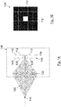
- FIG. 1A depicts a schematic two dimensional view of a plenoptic camera 100 comprising a main lens 102, a microlens array 104 (formed by a plurality of microlens 105 gathered in rows and columns) and an image sensor 106 positioned behind the microlens array 104 to sense intensity, color and directional information.
- the plenoptic camera 100 is capturing the incoming light rays 108 from an object point 110 placed at the conjugated plane of the microlens array 104.
- Figure 1B represents the light captured by the image sensor 106 of the plenoptic camera 100. Each cell of the grid represents the microimage 112 produced by each microlens 105 over the image sensor 106.
- the object point 110 When the image of an object point 110 is focused on the microlens array 104, the object point 110 is placed at the conjugated plane of the MLA through the main lens 102 of the plenoptic camera 100 and only an infinitesimal point over a microlens 105 is illuminated (actually, not an infinitesimal point but a diffraction pattern).
- the separation between the microlenses 105 and the image sensor 106 is approximately the focal length of the microlenses 105, all the pixels of the corresponding microimage 112 collect exactly the same light intensity, as shown in Figure 1B .
- the black colour is used to represent the lack of light and the whiter the pixels are, the more illuminated they are with grey levels meaning partial illuminations.
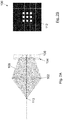
- object points 110 of the scene that are closer than the conjugated plane of the microlens array 104 in the object world will illuminate more microlenses 105 since the focus point in the image world would have been further than the microlens array 104 (more towards the right side), and the pattern captured by the sensor pixels will be different.
- the diagram of this scenario is illustrated in Figure 2A , whereas Figure 2B shows the corresponding pattern produced over the image sensor 106.
- an object point 110 that is further than the conjugated plane of the microlens array 104 illuminates also more microlenses 105 but now the focus point is closer to the main lens 102 than the microlens array 104 position and, thus, the pattern captured by the image sensor 106 differs from the two previous situations, as shown in Figures 3A and 3B .
- the grey levels in some of the microimages 112 correspond to pixels partially illuminated whereas in the white pixels the whole area of the pixel has been hit by the light coming from the object point 110 in the object world.
- FIG. 4A-4C depict, respectively for each one of scenarios of Figures 3A-3C , the generation process of horizontal epipolar images 400 (upper row) and vertical epipolar images 402 (lower row), by reorganizing the pixels captured by the image sensor 106.
- the object point 110 is placed at the conjugated plane of the microlens array 104
- Figure 4B the object point 110 is placed closer than the conjugated plane of the microlens array 104
- Figure 4C the object point 110 is placed further than the conjugated plane of the microlens array 104.
- Horizontal epipolar images 400 are formed by fixing the coordinates ( py,ly ) of the light field whereas vertical epipolar images 402 are formed by fixing the coordinates ( px,lx ) .
- the horizontal epipolar images 400 and the vertical epipolar images 402 are, respectively, horizontal-central epipolar images and vertical-central epipolar images since the pixels py and px which have been fixed for the epipolar images are the central-horizontal and central-vertical pixels of their respective microlenses.
- Figures 4A-4C shows how vertical epipolar images 402 (lower row) and horizontal epipolar images 400 (upper row) are formed directly from the captured light field.
- an epipolar line 430 (coloured in white) is formed. All the illuminated pixels (white pixels) of this epipolar line 430 correspond to the same object point 110 in the object world, as illustrated in the examples of Figures 1B-3B .
- An epipolar line 430 is a set of connected illuminated pixels (not black pixels) within an epipolar image which are detected as edges. Additionally, the slope of the epipolar line 430 is directly related to the type of pattern illuminated over the microlenses 104 and over the image sensor 106 and also to the corresponding depth of the object point 110 in the object world.
- a certain slope of an epipolar line 430 is unequivocally related to a certain depth of an object point 110 of the real three-dimensional world scene.
- the estimated slope of an epipolar line contains depth information of a certain object. Slope and depth are two sides of the same coin (it is possible to obtain depths from slopes in a deterministic way and vice versa, with only quantification errors in the conversions due to the fact that sensor pixels are not infinitesimal).
- the slope itself is sufficient to obtain information about the relative depth of the different objects of a scene. This relative information (i.e. the slope) can be useful for some applications in which it is not necessary to provide absolute depth information, such as identifying the different objects of a scene that are located at the same depth (same slope). Thus, in such scenarios the calculation of slopes is sufficient and the conversion slope to depth can be omitted.
- the method of the present invention is based on the calculation of depths only for the areas where there are edges on the projection of the world over the microlens array 104 (or what is the same, edges on the object world).
- a linear regression is applied to the illuminated pixels that form an epipolar line 430 in order to obtain a certain slope.
- all the plenoptic views distributed along the horizontal (px) or vertical ( py ) dimension are considered since the same object point 110 has been captured by all these views. Therefore, the linear regression technique reduces statistical noise by taking advantage of redundant information along one dimension.
- the method includes an additional stage to further reduce the statistical noise by analysing the same object point 110 in the horizontal 400 and vertical 402 epipolar images and considering the depth values obtained with the various epipolar images (400, 402) that contain information of the same object point 110 (for example, it is clear that a unique object point 110 in the object world, as shown in Figures 1 to 4 , produces several imprints in several points of the image sensor 106 and those imprints appear in several vertical and several horizontal epipolar images).
- all the epipolar lines 430 formed in the horizontal 400 and vertical 402 epipolar images are identified and the corresponding slope is calculated. Then, the corresponding depth of the object point 110 is calculated by considering the physical dimensions of the device.
- the output of this calculation process may be just the corresponding depth values of these detected slopes.
- the slopes obtained by analysing the horizontal 400 and vertical 402 epipolar images and epipolar lines 430 are combined into one four-dimensional matrix to reduce statistical noise, due to the fact that the reliability of the output is improved by redundancy of additional measurements since the same sensor pixel is considered when analysing both the vertical 402 and the horizontal 400 epipolar images and, thus, several slope values may have been produced by the same point of the object world.
- the slopes calculated are transformed to the corresponding object depths by considering the physical parameters of the plenoptic camera 100.
- this transformation stage is performed after combining all the redundant slopes, reducing drastically the number of slope-to-depth transformations.
- the previously generated four-dimensional matrix of depths/slopes is combined into a two-dimensional sparse depth/slope map (sparse because it offers readings only where there are edges in the object world), reducing even more the statistical noise and, thus, increasing the quality of the depth map.
- the depths/slopes calculated for the epipolar lines 430 in the horizontal 400 and vertical 402 epipolar images are directly combined into a two-dimensional sparse depth/slope map, therefore performing a single combination stage, what increases the computational efficiency.
- the sparse depth/slope map is filled by applying image filling techniques to obtain depth/slope values for every pixel ( dx,dy ).
- only the horizontal-central epipolar images (formed by setting the coordinate py to be equal to the centre pixel in the py dimension within a microimage 112), and/or only the vertical-central epipolar images (formed by taking the coordinate px equal to the centre pixel in the px dimension within a microimage), as shown in Figures 4A-4D are considered with the aim to reduce the number of epipolar images to analyse and, thus, increasing the performance at the cost of reducing the statistical redundancy.
- the method of the present invention can be implemented in mobile devices (e.g. smartphones, tablets or laptops) equipped with a plenoptic camera.
- Figure 5 shows a flow diagram of a method for generating depth maps according to an embodiment.
- the method In order to generate a depth map, the method generates horizontal 502 and vertical 503 epipolar images from a light field 501 captured by a plenoptic camera 100. For each horizontal 502 and vertical 503 epipolar image generated, the valid epipolar lines (510, 511) within epipolar images are identified. Then, the slopes (512, 513) of these valid epipolar lines (510, 511) are calculated and the corresponding depth values (514, 515) are finally obtained.
- Figure 5 describes the process of identifying and processing the valid epipolar lines (510, 511) taking as input a captured light field 501 and processing all the horizontal 502 and vertical 503 epipolar images ("EPIs" in Figure 5 ) performing the following steps:
- the noise reduction filter steps to obtain filtered horizontal 504 or vertical 505 epipolar images may be optionally discarded to increase the processing speed.
- the two slope matrices (obtained from the horizontal 502 and vertical 503 epipolar images) are combined into a single slope matrix and finally obtain a single depth matrix.
- the zero-crossings of the second spatial derivatives are identified by consecutive positive-negative or negative-positive values of the second derivative.
- the magnitude of the second derivative of these points is considered to determine where the actual zero-crossing is taking place.
- edge detection methods such as the Canny edge detector operator, curve fitting methods or moment-based methods
- the techniques described herein are not limited to the zero-crossing method. Nevertheless, it is extremely important to obtain the maximum accuracy as possible when determining the slope of the lines formed by the detected edges, that is why the sub-pixel precision to determine the edges is very important.
- One of the goals of the proposed method is to be computationally efficient (this requirement should be considered when choosing the edge detection algorithm to be employed).
- epipolar lines 430 are created by a change of contrast or a change of colour, and that is why epipolar lines 430 correspond to edges (changes of colour or contrast) in the object world.
- epipolar lines 430 are produced by object edges.
- the first derivative of the epipolar images i.e. over the intensity of the pixels
- provides the gradient i.e. the quickness with which the light intensity or contrast changes.
- the second derivative indicates where the contrast is changing quickest (which corresponds to object edges in the object world). Since the second derivative will not necessarily have the zero crossing at a given pixel (as it depends on the values of intensity of light in pixels, for example the epipolar image in Figure 6A has some grey level) the object edges are being determined with subpixel precision.
- the pixels that form a valid epipolar line (510, 511) within an epipolar image must necessarily be in neighbouring positions (i.e. the points that form a valid epipolar line must be connected) and must compose a line with all its points going towards the same direction as we go up-downwards or down upwards in the epipolar line.
- Figures 6A-6C depict an example ( Figure 6A ) of a valid epipolar line 610 in an epipolar image 600 and several examples ( Figures 6B and 6C ) of not-valid epipolar lines (612, 614) in respective epipolar images (602, 604).
- the neighbouring positions are considered when looking for edges in an epipolar image to form a valid epipolar line (starting from the central pixel detected as edge, the arrows in Figures 6A-6C represent the neighbouring positions which are considered for determining the connected edge pixels that form the epipolar line).
- epipolar lines 610 as the one shown in Figure 6A are considered as valid whereas epipolar lines 612 like the one shown in Figure 6B are detected as not-valid as the pixel at the top 620 and the pixel at the bottom 622 of the epipolar image 602 are not connected to the rest of the epipolar line 612.
- epipolar lines 614 as the one shown in Figure 6C may be considered as a valid epipolar line.
- these extreme pixels (630, 632) of these kind of lines can be omitted when calculating the slope of the epipolar lines, and still be considered as valid epipolar lines, as the outer pixels possibly come from aberrations of the main lens.
- the entire line can be labelled as not-valid in order to avoid performing calculations with not-valid epipolar lines.
- only the epipolar lines that have at least the same number of illuminated pixels than the height of the epipolar images are considered as valid lines. This can increase the accuracy of slope calculations in devices where aberrations have been practically corrected (optically or computationally in a previous stage).
- the highest aberrations of the main lens 102 are produced at the extremes of the lens (areas far from its centre in which the paraxial approximation is not valid anymore). All the light rays that pass through these extreme parts of the main lens 102 are more aberrated than the rays that crossed the lens nearer its centre. In a plenoptic camera 100 these rays are captured by the extreme pixels of every microimage 112, or extreme pixels of every microlens 104, which are also the extreme pixels 640 ( Figure 6A ) near the top or the bottom of epipolar images.
- the extreme pixels 640 of the epipolar images can be omitted to reduce the effects of optical aberrations as well as to increase the number of detected depth values (increasing the number of valid epipolar lines by disregarding extreme pixels). Therefore, epipolar lines that have fewer pixels than the height in pixels of the epipolar images can be considered as valid, as for example Figures 6B and 6C disregarding their top (620, 630) and bottom (622, 632) pixels.
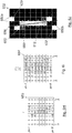
- Figures 6D-6G represent an example for the calculation process of the slope of the epipolar line 610 in epipolar image 600 of Figure 6A .
- the following intensity values "I" of the pixels have been considered, as shown in the table 642 of Figure 6D : a value of 0 for the black pixels, a value of 20 for dark grey pixels, a value of 60 for light grey pixels, and a value of 100 for the white pixels.
- Figure 6F depicts a graph 646 with the values of the second derivative (vertical axis) for every pixel px (horizontal axis) along the lx dimension (horizontal sub-axis), showing the zero-crossings 650 of the second derivative, identified by consecutive positive-negative or negative-positive values.
- the object edges in the object world are determined by detecting the zero-crossings 650 of the second spatial derivative.
- Figures 6H-6J represent another example for the calculation process of the slope of the epipolar line 612 in epipolar image 602 of Figure 6B .
- the intensity values I of the pixels are shown in table 653 of Figure 6H , whereas table 654 of Figure 6I represents the second derivative values.
- the zero-crossings 650 are computed and shown as dots in Figure 6J .
- the slope of the epipolar line 612 is computed by applying a linear regression 658 to the detected zero-crossings 650. Note that the linear regression 658 of the epipolar line 612 in Figure 6J has a higher slope than the linear regression 656 of the epipolar line 610 in Figure 6G due to the zero-crossings 650a and 650b obtained from the pixels 620 and 622 respectively.
- all the zero-crossings are considered in the linear regression. However, in another embodiment some of the zero-crossings may be previously discarded and not considered in the process of obtaining the slope of the epipolar lines.
- the points with high dispersion in comparison with the rest of the points that are used to apply the linear regression technique can be identified and excluded from this process in order to obtain a more accurate slope estimation or to eliminate outliers.
- the zero-crossing 650a originated by the top pixel 620 and the zero-crossing 650b originated by the bottom pixel 622 of the epipolar image 602 may be discarded when computing the linear regression 658 (obtaining an epipolar line with a slope similar to the slope obtained for the epipolar line 610 of Figure 6G ), since the top 620 and bottom 622 pixels are not connected to the rest of the pixels that originate the epipolar line 612 (in this case the top 620 and bottom 622 pixels may have been caused by aberrations of the main lens 102).
- the second derivatives 644 are computed, it is decided whether they define valid or not-valid epipolar lines. For this process, some values of the second derivatives corresponding to some pixels may be discarded, as previously explained. A linear regression is applied to the valid zero-crossings to calculate their corresponding slopes. Conversely, for all those epipolar lines identified as not-valid, no further calculation need to be performed.
- an error estimation may also be calculated.
- the sum of the distances between the points of the epipolar line (i.e. the zero-crossings) and the final estimated regression line can be used as error (i.e. the addition of the absolute values of the distances between the epipolar line calculated and the points used to calculate this epipolar line).
- error i.e. the addition of the absolute values of the distances between the epipolar line calculated and the points used to calculate this epipolar line.
- any other type of error computation may be defined.
- a maximum error threshold can be used to discard (and not consider in the rest of the algorithm) an epipolar line. To that end, if the computed error is higher than the maximum error threshold the epipolar line is deemed not-valid, and if the computed error is lower than the maximum error threshold the epipolar line is deemed valid.
- a horizontal epipolar image 400 may contain several epipolar lines (up to Nlx epipolar lines), as shown for instance in the detected valid epipolar lines 510 of a horizontal epipolar image 502 in Figure 5 .
- a vertical epipolar image may contain several epipolar lines 511 (up to Nly epipolar lines).
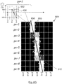
- Figure 7A shows an example of a horizontal epipolar image 700 including two different epipolar lines (710 and 712 in Figure 7E ).
- Figure 7A shows the linear regressions (756, 758) of the zero-crossings 650 corresponding to both epipolar lines. This example represents a more realistic scenario than those presented in Figures 4 and 6 since the light pattern is now produced by an object with a certain size instead of infinitesimal. That is why the high intensity (white pixels) recorded by the image sensor 106 occupies several microlenses (Ix) in Figure 7A .
- the intensity values "I" of the pixels of the epipolar image 700 are shown in table 720 of Figure 7B , whereas table 730 of Figure 7C represents the second derivative values.
- the method to consider whether a pixel of an epipolar image is labelled or detected as edge pixel 731 or not comprises finding those pixels (px,lx) with a negative value of the second derivative that have at their right or left side a pixel with a positive second derivative (highlighted pixels of Figure 7C ).
- a pixel of an epipolar image may be labelled as edge pixel 731 for those pixels (px,lx) with a positive value of the second derivative that have at their right or left side a pixel with a negative second derivative (highlighted pixels of Figure 7D ).
- edge pixels 731 have been detected, according to an embodiment the procedure to identify valid epipolar lines within epipolar images is herewith explained, making reference to the example of Figure 7E (corresponding to the second derivative values and edge pixels 731 of Figure 7C ):
- both these two criteria (number of edge pixels 731 detected for an epipolar line and consistency of the direction) must be complied with for the epipolar line to be considered a valid one.
- the output of the method is a sparse two-dimensional depth map containing the depth values (dz) of the edges of the objects of the scene captured by a plenoptic camera.
- the coordinates ( dx,dy ) of the depth map indicate the lateral position of the corresponding object points (i.e. the two-dimensional coordinates of the object world), whereas the depth values (dz) represent the depth of the corresponding coordinates ( dx,dy ) in the object world.
- Figure 8 illustrates the edges of a sparse depth map showing three objects (802, 804, 806) at different depths, wherein black colour represents no depth value assigned and the whiter the depth value, the further is the object in the scene.
- the method may comprise an additional stage to generate a sparse depth map considering the slope of the epipolar lines obtained in the previous stage.
- the sparse depth map is obtained by assigning depth values (dz) of objects in the real world to the edges calculated before ( dx,dy ).
- the input to the sparse depth map generation are two matrices (a horizontal depth matrix 516, and a vertical depth matrix 517 relating the calculated depth values (dz) and the corresponding position in the light-field structure ( px,py,lx,ly ).
- the input to the sparse depth map generation can also be the two matrices of slopes (512, 513) obtained in a previous step. In this case, a sparse slope map is first obtained and the conversion to depth is only applied to this two-dimensional slope map, thus, reducing the computational requirements.
- the horizontal depth matrix 516 is obtained by analysing the horizontal epipolar images whereas the vertical depth matrix 517 is obtained from the vertical epipolar images.
- the size of each of these matrices in the state of the art (516, 517) is Npx ⁇ Npy ⁇ Nlx ⁇ Nly, being Npx and Npy the number of pixels per microimage in the horizontal and vertical directions, and Nlx and Nly the number of horizontal and vertical microlenses.
- the size of the input matrices of this stage can be greatly reduced to store only the depth/slope value for every epipolar line produced by the linear regression method, such that the size of the horizontal depth matrix is Npy ⁇ Nly ⁇ Nlx (an horizontal epipolar image may contain up to Nlx epipolar lines) and the size of the vertical depth matrix is Npx ⁇ Nlx ⁇ Nly (a vertical epipolar image may contain up to Nly epipolar lines).
- the two depth/slope matrices may include only the points analysed in the horizontal-central and vertical-central epipolar images (or any other epipolar image), such that the sizes of the matrices is Nlx ⁇ Nly for both of them.
- a combination stage may be used to assign every depth value obtained ( dz ) to the two-dimensional coordinates of the object world (dx,dy), obtaining the depth map ( dx,dy,dz ) depending on the calculated slope of the points and considering the coordinates ( px,py,lx,ly ) of the points (namely the position over the sensor).
- an object point 110 produces different patterns over the sensor as well as different slopes on the epipolar lines.
- the slope and knowing the position ( px,py,lx,ly ) over the sensor it is possible to find the corresponding world position ( dx,dy ) for every detected epipolar line.
- dz values may be obtained for the same pair ( dx,dy ), as a single edge in the object world can originate several epipolar lines affected by slightly different noise, aberrations, occlusions or quantization errors, yielding epipolar lines with different slopes and hence different depths. Also some of the horizontal and some of the vertical epipolar lines might yield slightly different dz values.
- all the redundant depth values are combined into a single depth map in order to reduce statistical noise when generating the two-dimensional depth map (a single dz value per dx,dy coordinates).
- the error estimation calculated for the epipolar lines can be considered in order to choose the final depth value (dz) of a certain position of the depth map ( dx,dy ); for example, by choosing the value with the lowest error among all the values that were projected to the same position ( dx,dy ) (for example, considering as error the addition of all the distances between the epipolar line and the pixels that originated that epipolar line or any other measurement).
- the redundancy considered by the algorithms can be decreased, reducing also the quality of the depth map, in order to reduce the computational requirements and complexity of the implementation.
- the two-dimensional sparse depth map is directly generated by taking a certain plenoptic view of horizontal (or vertical) epipolar structure that contains the estimated depth values, i.e. by taking all the points with px and/or py set to certain pixels (typically the central pixel since it is the view less affected by aberrations).
- the computational complexity is reduced at the expense to have less redundant and possibly sparser depth maps (only a depth value for every microlens).
- the resolution of the depth map can be higher than the total number of microlenses in order to take advantage of the subpixel-accuracy obtained in the zero-crossing border detection stage.
- the sparse depth map obtained in the previous stage contains a lot of empty positions ( dx,dy ), not only for a large number of pixels, but also for a large number of microlenses in which the homogeneity of the real world does not produce edges on the epipolar images.
- the corresponding depth values for all this empty positions can be obtained by considering the depth values of the neighbouring positions. This procedure to obtain a dense depth map can be called "depth map filling" and takes profit of lots of previous art in image filling techniques.
- Figure 9 depicts an example of a dense depth map showing three objects (902, 904, 906) at different depths.
- This Figure 9 shows in grey levels a dense depth map of the sparse depth map generated in Figure 8 , wherein black colour represents no depth value assigned and the whiter the depth value, the further is the object in the scene.
- the method of the present invention is executed in an electronic mobile device, such as a smartphone, a tablet or a laptop.
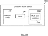
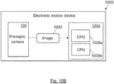
- Figures 10A , 10B and 10C illustrates different embodiments of electronic mobile devices 1000 with a processing unit or processing means 1004 configured to execute the method in order to obtain depth maps from images 1002 captured by a plenoptic camera 100.
- two CPU execution threads are created so that a first CPU 1008a (in Figure 10B ) executes the described steps (see Figure 5 ) for the horizontal epipolar images 502 whereas a second CPU 1008b is in charge of performing the same operations on the vertical epipolar images 503.
- GPU 1010 in Figure 10C graphics processing unit 1010 in Figure 10C
- a GPU includes several hundreds or thousands of cores capable of executing operations simultaneously.
- each epipolar image vertical and horizontal is processed simultaneously in a different core of a GPU 1010 to further accelerate the execution of the algorithm.
Landscapes
- Engineering & Computer Science (AREA)
- Physics & Mathematics (AREA)
- General Physics & Mathematics (AREA)
- Theoretical Computer Science (AREA)
- Computer Vision & Pattern Recognition (AREA)
- Length Measuring Devices By Optical Means (AREA)
- Image Processing (AREA)
- Studio Devices (AREA)
- Image Analysis (AREA)
- Testing, Inspecting, Measuring Of Stereoscopic Televisions And Televisions (AREA)
- Measurement Of Optical Distance (AREA)
- Radar Systems Or Details Thereof (AREA)
Claims (15)
- Verfahren zum Erhalten von Tiefeninformationen aus einem Lichtfeld, Folgendes umfassend:Erzeugen einer Vielzahl von Epipolarbildern (502, 503) aus einem Lichtfeld (501), welches von einer Lichtfelderfassungsvorrichtung (100) aufgenommen wird;einen Kantendetektionsschritt (508, 509) zum Detektieren, in den Epipolarbildern (502, 503), von Kantenpixeln (731), die den Kanten von Objekten in der Szene entsprechen, die von der Lichtfelderfassungsvorrichtung (100) aufgenommen wird;wobei das Verfahren weiter Folgendes umfasst:in jedem Epipolarbild (502, 503) das Detektieren von gültigen Epipolarlinien (510, 511), die durch einen Satz von Kantenpixeln (731) gebildet werden, wobei alle Kantenpixel (731), die die gültigen Epipolarlinien bilden, verbunden sind und eine einheitliche Richtung für die gültige Epipolarlinie bilden;Bestimmen der Steigungen (512, 513) der gültigen Epipolarlinien (510, 511).
- Verfahren gemäß Anspruch 1, wobei der Kantendetektionsschritt (508, 509) die Berechnung einer zweiten räumlichen Ableitung (506, 507) für jedes Pixel der Epipolarbilder (502, 503) und das Detektieren der Nulldurchgänge der zweiten räumlichen Ableitungen umfasst.
- Verfahren gemäß einem der vorhergehenden Ansprüche, wobei der Schritt des Bestimmens der Steigungen (512, 513) der gültigen Epipolarlinien (510, 511) das Anwenden einer Linienanpassung auf die detektierten Kantenpixel (731) umfasst.
- Verfahren gemäß einem der vorhergehenden Ansprüche, wobei das Detektieren gültiger Epipolarlinien (510, 511) in einem Epipolarbild (502, 503) das Bestimmen von Epipolarlinien als einen Satz von verbundenen Kantenpixeln (731) und das Analysieren der Epipolarlinien umfasst, um zu bestimmen, ob die Epipolarlinien gültig sind oder nicht.
- Verfahren gemäß Anspruch 4, wobei die Analyse der Epipolarlinien, um zu bestimmen, ob sie gültig sind oder nicht, das Überprüfen der Anzahl von Pixeln, die die Epipolarlinie (710, 712) bilden, die einen bestimmten Schwellenwert übersteigt, umfasst.
- Verfahren gemäß Anspruch 5, wobei die Anzahl der Pixel, die die Epipolarlinie (710, 712) bilden, mindestens gleich der Anzahl der Pixel der Höhe des entsprechenden Epipolarbildes (502, 503) sein muss.
- Verfahren gemäß Anspruch 4, wobei die Analyse der Epipolarlinien, um zu bestimmen, ob die Epipolarlinien gültig sind oder nicht, eines der Folgenden umfasst:- eine morphologische Analyse;- ein heuristisches Verfahren;- einen Algorithmus zum maschinellen Lernen.
- Verfahren gemäß einem der Ansprüche 4 bis 7, wobei die Analyse der Epipolarlinien einschließt, dass ein oder mehrere Endpixel (630, 632) am oberen und/oder unteren Rand des Epipolarbildes (502, 503) nicht berücksichtigt werden.
- Verfahren gemäß Anspruch 8, wobei die Endpixel (630, 632) nicht berücksichtigt werden, wenn die Endpixel (630, 632) nicht in dieselbe Richtung wie der Rest der Kantenpixel (731) zeigen, die die Epipolarlinie bilden.
- Verfahren gemäß einem der vorhergehenden Ansprüche, welches weiter die Erzeugung einer einzigen Steigungs- oder Tiefenkarte aus einer Kombination redundanter Steigungen oder Tiefen umfasst, die aus verschiedenen gültigen Epipolarlinien (510, 511) von horizontalen Epipolarbildern (502) und vertikalen Epipolarbildern (503) für dieselbe Position (dx, dy) erhalten werden.
- Verfahren gemäß einem der vorhergehenden Ansprüche, welches die Erzeugung einer Steigungskarte und/oder einer Tiefenkarte umfasst, wobei die Anzahl der Positionen (dx, dy) der Steigungs- und/oder Tiefenkarte höher ist als die Anzahl der Mikrolinsen unter Verwendung der in den Nulldurchgängen erhaltenen Subpixelgenauigkeit.
- Vorrichtung zum Erzeugen einer Tiefenkarte aus einem Lichtfeld, die Verarbeitungsmittel (1004) umfasst, die so ausgebildet sind, dass sie alle Schritte des Verfahrens gemäß einem der Ansprüche 1 bis 11 ausführen.
- Vorrichtung gemäß Anspruch 12, welches eine Lichtfelderfassungsvorrichtung (100) umfasst.
- Computerprogrammprodukt zum Erzeugen einer Tiefenkarte aus einem von einer plenoptischen Kamera aufgenommenen Bild, umfassend Computercode-Anweisungen, die, wenn sie von einem Prozessor ausgeführt werden, den Prozessor veranlassen, das Verfahren gemäß einem der Ansprüche 1 bis 11 durchzuführen.
- Computerprogrammprodukt gemäß Anspruch 14, welches mindestens ein computerlesbares Speichermedium umfasst, auf dem die Computercode-Anweisungen aufgezeichnet sind.
Applications Claiming Priority (1)
| Application Number | Priority Date | Filing Date | Title |
|---|---|---|---|
| PCT/EP2016/074992 WO2018072817A1 (en) | 2016-10-18 | 2016-10-18 | A device and method for obtaining distance information from views |
Publications (3)
| Publication Number | Publication Date |
|---|---|
| EP3516625A1 EP3516625A1 (de) | 2019-07-31 |
| EP3516625B1 true EP3516625B1 (de) | 2020-11-25 |
| EP3516625B8 EP3516625B8 (de) | 2021-04-21 |
Family
ID=57184433
Family Applications (2)
| Application Number | Title | Priority Date | Filing Date |
|---|---|---|---|
| EP16784856.3A Active EP3516625B8 (de) | 2016-10-18 | 2016-10-18 | Vorrichtung und verfahren zur gewinnung von entfernungsinformationen aus ansichten |
| EP16816689.0A Active EP3516626B1 (de) | 2016-10-18 | 2016-12-20 | Vorrichtung und verfahren zum erhalten von entfernungsinformationen aus ansichten |
Family Applications After (1)
| Application Number | Title | Priority Date | Filing Date |
|---|---|---|---|
| EP16816689.0A Active EP3516626B1 (de) | 2016-10-18 | 2016-12-20 | Vorrichtung und verfahren zum erhalten von entfernungsinformationen aus ansichten |
Country Status (9)
| Country | Link |
|---|---|
| US (2) | US11423562B2 (de) |
| EP (2) | EP3516625B8 (de) |
| JP (2) | JP6855587B2 (de) |
| KR (2) | KR102674646B1 (de) |
| CN (2) | CN109997170B (de) |
| CA (2) | CA3040002C (de) |
| ES (2) | ES2866975T3 (de) |
| IL (2) | IL266041B (de) |
| WO (2) | WO2018072817A1 (de) |
Families Citing this family (45)
| Publication number | Priority date | Publication date | Assignee | Title |
|---|---|---|---|---|
| US11972586B2 (en) | 2015-02-13 | 2024-04-30 | Carnegie Mellon University | Agile depth sensing using triangulation light curtains |
| US11425357B2 (en) | 2015-02-13 | 2022-08-23 | Carnegie Mellon University | Method for epipolar time of flight imaging |
| US11493634B2 (en) | 2015-02-13 | 2022-11-08 | Carnegie Mellon University | Programmable light curtains |
| US10679370B2 (en) * | 2015-02-13 | 2020-06-09 | Carnegie Mellon University | Energy optimized imaging system with 360 degree field-of-view |
| US11747135B2 (en) * | 2015-02-13 | 2023-09-05 | Carnegie Mellon University | Energy optimized imaging system with synchronized dynamic control of directable beam light source and reconfigurably masked photo-sensor |
| FR3051584B1 (fr) * | 2016-05-20 | 2019-11-01 | Safran | Procede de reconstruction tridimensionnelle a l'aide d'une camera plenoptique. |
| EP3510562A1 (de) | 2016-09-07 | 2019-07-17 | Starship Technologies OÜ | Verfahren und vorrichtung zur kalibrierung mehrerer kameras |
| US10430994B1 (en) * | 2016-11-07 | 2019-10-01 | Henry Harlyn Baker | Techniques for determining a three-dimensional textured representation of a surface of an object from a set of images with varying formats |
| US11652978B2 (en) * | 2017-01-05 | 2023-05-16 | Eys3D Microelectronics, Co. | Depth map generation device |
| EP3416371A1 (de) * | 2017-06-12 | 2018-12-19 | Thomson Licensing | Verfahren zur anzeige, auf einer 2d-anzeige, eines inhalts aus lichtfelddaten |
| EP3416381A1 (de) | 2017-06-12 | 2018-12-19 | Thomson Licensing | Verfahren und vorrichtung zur bereitstellung von informationen für einen benutzer zur beobachtung von inhalt mit mehreren ansichten |
| US11393114B1 (en) * | 2017-11-08 | 2022-07-19 | AI Incorporated | Method and system for collaborative construction of a map |
| EP3486606B1 (de) * | 2017-11-20 | 2026-05-20 | Leica Geosystems Ag | Stereokamera und stereophotogrammetrisches verfahren |
| EP3779892A4 (de) * | 2018-04-12 | 2021-05-05 | Toppan Printing Co., Ltd. | Lichtfeldbilderzeugungssystem, bildanzeigesystem, forminformationserfassungsserver, bilderzeugungsserver, anzeigevorrichtung, lichtfeldbilderzeugungsverfahren und bildanzeigeverfahren |
| DE102019205783A1 (de) | 2018-04-23 | 2019-10-24 | Cognex Corporation | Systeme und Verfahren für verbesserte 3D-Daten-Rekonstruktion aus stereo-temporalen Bildsequenzen |
| EP3572971B1 (de) * | 2018-05-22 | 2021-02-24 | Sick Ag | Absichern eines überwachungsbereichs mit mindestens einer maschine |
| EP3598390A1 (de) * | 2018-07-19 | 2020-01-22 | Thomson Licensing | Verfahren zur schätzung der tiefe für pixel, zugehörige vorrichtung und computerprogrammprodukt |
| US11440744B2 (en) * | 2018-07-30 | 2022-09-13 | Laitram, L.L.C. | Conveyor package-flow measuring system |
| CN109344818B (zh) * | 2018-09-28 | 2020-04-14 | 合肥工业大学 | 一种基于深度卷积网络的光场显著目标检测方法 |
| KR102689953B1 (ko) * | 2018-12-03 | 2024-07-31 | 삼성전자주식회사 | 캘리브레이션 방법 및 장치 |
| EP3671645A1 (de) * | 2018-12-20 | 2020-06-24 | Carl Zeiss Vision International GmbH | Verfahren und vorrichtung zum erzeugen einer 3d-rekonstruktion eines objekts |
| KR102606835B1 (ko) * | 2019-02-20 | 2023-11-29 | 삼성전자주식회사 | 뎁스 맵을 생성하는 전자 장치 및 방법 |
| CN111862098B (zh) * | 2019-04-30 | 2023-11-24 | 曜科智能科技(上海)有限公司 | 基于光场语义的个体匹配方法、装置、设备和介质 |
| CN112446909B (zh) * | 2019-08-30 | 2022-02-01 | 上海商汤临港智能科技有限公司 | 一种深度图像补全方法及装置、计算机可读存储介质 |
| CN110827343B (zh) * | 2019-11-06 | 2024-01-26 | 太原科技大学 | 基于能量增强散焦响应的改进光场深度估计方法 |
| CN112907701B (zh) * | 2019-11-19 | 2022-08-05 | 杭州海康威视数字技术股份有限公司 | 获取图像的方法、装置、计算机设备和存储介质 |
| EP4094186A4 (de) * | 2020-01-21 | 2024-01-24 | Proprio, Inc. | Verfahren und systeme zum erweitern von tiefendaten aus einem tiefensensor wie etwa mit daten aus einem mehrsichtkamerasystem |
| CN112750156B (zh) * | 2020-03-16 | 2022-09-09 | 奕目(上海)科技有限公司 | 光场成像系统、处理方法和装置 |
| CN111724373B (zh) * | 2020-06-22 | 2024-05-14 | 江西财经大学 | 一种基于感知加密光场图像的视觉安全性度量方法 |
| KR20220010297A (ko) | 2020-07-17 | 2022-01-25 | 에스케이하이닉스 주식회사 | 엣지 기반 샤프니스 세기 제어 회로, 이미지 센싱 장치 및 그 동작방법 |
| CN111986086B (zh) * | 2020-08-27 | 2021-11-09 | 贝壳找房(北京)科技有限公司 | 三维图像优化生成方法及系统 |
| CN112595238B (zh) * | 2020-11-25 | 2022-09-27 | 四川云盾光电科技有限公司 | 一种高低速兼容直线位移增量精密测量方法 |
| KR20220170090A (ko) * | 2021-06-22 | 2022-12-29 | 에스케이하이닉스 주식회사 | 멀티-뷰 이미지에서 노이즈 감소를 위한 장치 및 방법 |
| CN114078153B (zh) * | 2021-11-18 | 2022-06-14 | 清华大学 | 面向散射场景的光场编码摄像方法及装置 |
| JP7398749B2 (ja) * | 2021-12-06 | 2023-12-15 | 国立大学法人東北大学 | 3次元形状計測方法及び3次元形状計測装置 |
| KR20230152387A (ko) | 2022-04-27 | 2023-11-03 | 에스케이하이닉스 주식회사 | 이미지 처리 시스템 및 이미지 처리 방법 |
| CN114897952B (zh) * | 2022-05-30 | 2023-04-04 | 中国测绘科学研究院 | 一种自适应遮挡的单张光场影像准确深度估计方法及系统 |
| CN115359105B (zh) * | 2022-08-01 | 2023-08-11 | 荣耀终端有限公司 | 景深扩展图像生成方法、设备及存储介质 |
| US12335637B2 (en) | 2023-01-25 | 2025-06-17 | Adeia Imaging Llc | Non-planar lenticular arrays for light field image capture |
| US12439174B2 (en) * | 2023-01-25 | 2025-10-07 | Adeia Imaging Llc | Non-planar lenticular arrays for light field image capture |
| US12468909B2 (en) | 2023-02-24 | 2025-11-11 | Zebra Technologies Corporation | Use of distance measurement to aid in vision applications in handheld scanner devices |
| CN116883445B (zh) * | 2023-08-10 | 2025-04-08 | 武汉中观自动化科技有限公司 | 工件边缘测量方法、装置、电子设备及存储介质 |
| CN117308967B (zh) * | 2023-11-30 | 2024-02-02 | 中船(北京)智能装备科技有限公司 | 一种目标对象位置信息的确定方法、装置及设备 |
| CN118674741B (zh) * | 2024-06-18 | 2025-10-21 | 浙江大学 | 基于灰度矩模型的亚像素边缘跟踪方法、设备及介质 |
| CN119537983B (zh) * | 2025-01-23 | 2025-05-16 | 四川警察学院 | 一种基于自适应dbscan聚类的弹壳底火测量异常区域检测方法 |
Family Cites Families (33)
| Publication number | Priority date | Publication date | Assignee | Title |
|---|---|---|---|---|
| JP2941139B2 (ja) * | 1993-03-11 | 1999-08-25 | 凸版印刷株式会社 | 視差画像作成方法および装置 |
| KR19980702008A (ko) * | 1995-02-03 | 1998-07-15 | 마이클 지. 가브리지 | 광학 시스템의 필드 심도를 증가시키기 위한 방법 및 장치 |
| US6009188A (en) * | 1996-02-16 | 1999-12-28 | Microsoft Corporation | Method and system for digital plenoptic imaging |
| US6201899B1 (en) * | 1998-10-09 | 2001-03-13 | Sarnoff Corporation | Method and apparatus for extended depth of field imaging |
| JP2004037657A (ja) * | 2002-07-01 | 2004-02-05 | Olympus Corp | 広角測距視野カメラ |
| CA2511040A1 (en) | 2004-09-23 | 2006-03-23 | The Governors Of The University Of Alberta | Method and system for real time image rendering |
| US8194168B2 (en) * | 2005-06-03 | 2012-06-05 | Mediapod Llc | Multi-dimensional imaging system and method |
| US7620309B2 (en) * | 2006-04-04 | 2009-11-17 | Adobe Systems, Incorporated | Plenoptic camera |
| US8090194B2 (en) * | 2006-11-21 | 2012-01-03 | Mantis Vision Ltd. | 3D geometric modeling and motion capture using both single and dual imaging |
| US8538166B2 (en) * | 2006-11-21 | 2013-09-17 | Mantisvision Ltd. | 3D geometric modeling and 3D video content creation |
| US7769205B2 (en) * | 2006-11-28 | 2010-08-03 | Prefixa International Inc. | Fast three dimensional recovery method and apparatus |
| US8290358B1 (en) * | 2007-06-25 | 2012-10-16 | Adobe Systems Incorporated | Methods and apparatus for light-field imaging |
| JP4856611B2 (ja) * | 2007-10-29 | 2012-01-18 | 富士重工業株式会社 | 物体検出装置 |
| US7949252B1 (en) * | 2008-12-11 | 2011-05-24 | Adobe Systems Incorporated | Plenoptic camera with large depth of field |
| US8938099B2 (en) * | 2010-12-15 | 2015-01-20 | Canon Kabushiki Kaisha | Image processing apparatus, method of controlling the same, distance measurement apparatus, and storage medium |
| US9607424B2 (en) * | 2012-06-26 | 2017-03-28 | Lytro, Inc. | Depth-assigned content for depth-enhanced pictures |
| KR102111181B1 (ko) * | 2012-08-21 | 2020-05-15 | 포토내이션 리미티드 | 어레이 카메라를 사용하여 포착된 영상에서의 시차 검출 및 보정을 위한 시스템 및 방법 |
| GB201302694D0 (en) * | 2013-02-15 | 2013-04-03 | Oxford Instr Nanotechnology Tools Ltd | Method of electron beam diffraction analysis |
| WO2014133974A1 (en) * | 2013-02-24 | 2014-09-04 | Pelican Imaging Corporation | Thin form computational and modular array cameras |
| WO2014165244A1 (en) * | 2013-03-13 | 2014-10-09 | Pelican Imaging Corporation | Systems and methods for synthesizing images from image data captured by an array camera using restricted depth of field depth maps in which depth estimation precision varies |
| US9786062B2 (en) * | 2013-05-06 | 2017-10-10 | Disney Enterprises, Inc. | Scene reconstruction from high spatio-angular resolution light fields |
| WO2014198351A1 (en) * | 2013-06-12 | 2014-12-18 | Vidinoti Sa | Method and apparatus for identifying local features |
| US9451162B2 (en) * | 2013-08-21 | 2016-09-20 | Jaunt Inc. | Camera array including camera modules |
| JP6026979B2 (ja) * | 2013-09-06 | 2016-11-16 | 日本電信電話株式会社 | 画像処理装置、画像処理方法及び画像処理プログラム |
| WO2015051282A2 (en) * | 2013-10-03 | 2015-04-09 | Jingyi Yu | Xslit camera |
| JP6114229B2 (ja) | 2014-04-28 | 2017-04-12 | 日本電信電話株式会社 | 画像生成装置及び画像生成プログラム |
| US8988317B1 (en) * | 2014-06-12 | 2015-03-24 | Lytro, Inc. | Depth determination for light field images |
| US10008027B1 (en) * | 2014-10-20 | 2018-06-26 | Henry Harlyn Baker | Techniques for determining a three-dimensional representation of a surface of an object from a set of images |
| US9292926B1 (en) * | 2014-11-24 | 2016-03-22 | Adobe Systems Incorporated | Depth map generation |
| CN104598744B (zh) * | 2015-01-27 | 2017-11-21 | 北京工业大学 | 一种基于光场的深度估计方法 |
| US9661308B1 (en) * | 2015-04-20 | 2017-05-23 | Samsung Electronics Co., Ltd. | Increasing tolerance of sensor-scanner misalignment of the 3D camera with epipolar line laser point scanning |
| CN104851089A (zh) * | 2015-04-28 | 2015-08-19 | 中国人民解放军国防科学技术大学 | 一种基于三维光场的静态场景前景分割方法和装置 |
| CN105023249B (zh) * | 2015-06-26 | 2017-11-17 | 清华大学深圳研究生院 | 基于光场的高光图像修复方法及装置 |
-
2016
- 2016-10-18 CN CN201680091169.XA patent/CN109997170B/zh active Active
- 2016-10-18 JP JP2019541848A patent/JP6855587B2/ja active Active
- 2016-10-18 ES ES16784856T patent/ES2866975T3/es active Active
- 2016-10-18 US US16/342,735 patent/US11423562B2/en active Active
- 2016-10-18 WO PCT/EP2016/074992 patent/WO2018072817A1/en not_active Ceased
- 2016-10-18 KR KR1020197014305A patent/KR102674646B1/ko active Active
- 2016-10-18 IL IL266041A patent/IL266041B/en unknown
- 2016-10-18 EP EP16784856.3A patent/EP3516625B8/de active Active
- 2016-10-18 CA CA3040002A patent/CA3040002C/en active Active
- 2016-12-20 US US16/342,739 patent/US10832429B2/en active Active
- 2016-12-20 JP JP2019541849A patent/JP7043085B2/ja active Active
- 2016-12-20 EP EP16816689.0A patent/EP3516626B1/de active Active
- 2016-12-20 KR KR1020197014170A patent/KR102785831B1/ko active Active
- 2016-12-20 CA CA3040006A patent/CA3040006C/en active Active
- 2016-12-20 ES ES16816689T patent/ES2864834T3/es active Active
- 2016-12-20 WO PCT/EP2016/081966 patent/WO2018072858A1/en not_active Ceased
- 2016-12-20 CN CN201680091175.5A patent/CN110036410B/zh active Active
-
2019
- 2019-04-15 IL IL266036A patent/IL266036B/en active IP Right Grant
Non-Patent Citations (1)
| Title |
|---|
| None * |
Also Published As
| Publication number | Publication date |
|---|---|
| JP6855587B2 (ja) | 2021-04-07 |
| CA3040006A1 (en) | 2018-04-26 |
| KR20190076998A (ko) | 2019-07-02 |
| US10832429B2 (en) | 2020-11-10 |
| KR20190065432A (ko) | 2019-06-11 |
| US20190236796A1 (en) | 2019-08-01 |
| KR102674646B1 (ko) | 2024-06-13 |
| EP3516626A1 (de) | 2019-07-31 |
| EP3516625A1 (de) | 2019-07-31 |
| IL266041A (en) | 2019-06-30 |
| EP3516625B8 (de) | 2021-04-21 |
| JP2020503817A (ja) | 2020-01-30 |
| CN109997170A (zh) | 2019-07-09 |
| CN110036410B (zh) | 2023-06-30 |
| CA3040006C (en) | 2023-09-26 |
| IL266036B (en) | 2021-02-28 |
| CN110036410A (zh) | 2019-07-19 |
| CA3040002C (en) | 2023-12-12 |
| JP2019532451A (ja) | 2019-11-07 |
| JP7043085B2 (ja) | 2022-03-29 |
| ES2864834T3 (es) | 2021-10-14 |
| US11423562B2 (en) | 2022-08-23 |
| EP3516626B1 (de) | 2020-11-25 |
| IL266041B (en) | 2022-09-01 |
| WO2018072858A1 (en) | 2018-04-26 |
| IL266036A (en) | 2019-06-30 |
| US20200051266A1 (en) | 2020-02-13 |
| ES2866975T3 (es) | 2021-10-20 |
| KR102785831B1 (ko) | 2025-03-26 |
| CA3040002A1 (en) | 2018-04-26 |
| WO2018072817A1 (en) | 2018-04-26 |
| CN109997170B (zh) | 2023-08-11 |
Similar Documents
| Publication | Publication Date | Title |
|---|---|---|
| US11423562B2 (en) | Device and method for obtaining distance information from views | |
| US10699476B2 (en) | Generating a merged, fused three-dimensional point cloud based on captured images of a scene | |
| US8988317B1 (en) | Depth determination for light field images | |
| JP6509914B2 (ja) | 深度推定のための画像センサ | |
| CA2961921A1 (en) | Camera calibration method using a calibration target | |
| US9818199B2 (en) | Method and apparatus for estimating depth of focused plenoptic data | |
| EP3182372B1 (de) | Verfahren und system zur schätzung der position einer projektion eines hauptstrahls auf einem sensor einer lichtfelderfassungsvorrichtung | |
| CN104813217B (zh) | 用于设计能够估计景深的无源单通道成像器的方法 | |
| KR20170088859A (ko) | 비집속 플렌옵틱 데이터의 깊이를 추정하는 방법 및 장치 | |
| JP2018133064A (ja) | 画像処理装置、撮像装置、画像処理方法および画像処理プログラム | |
| US12079968B2 (en) | Apparatus and method for noise reduction from a multi-view image | |
| JP2018081378A (ja) | 画像処理装置、撮像装置、画像処理方法および画像処理プログラム | |
| JP2018156192A (ja) | 画像処理装置、画像処理システム、画像処理方法、およびプログラム | |
| CN111080689A (zh) | 确定面部深度图的方法和装置 |
Legal Events
| Date | Code | Title | Description |
|---|---|---|---|
| STAA | Information on the status of an ep patent application or granted ep patent |
Free format text: STATUS: UNKNOWN |
|
| STAA | Information on the status of an ep patent application or granted ep patent |
Free format text: STATUS: THE INTERNATIONAL PUBLICATION HAS BEEN MADE |
|
| PUAI | Public reference made under article 153(3) epc to a published international application that has entered the european phase |
Free format text: ORIGINAL CODE: 0009012 |
|
| STAA | Information on the status of an ep patent application or granted ep patent |
Free format text: STATUS: REQUEST FOR EXAMINATION WAS MADE |
|
| 17P | Request for examination filed |
Effective date: 20190422 |
|
| AK | Designated contracting states |
Kind code of ref document: A1 Designated state(s): AL AT BE BG CH CY CZ DE DK EE ES FI FR GB GR HR HU IE IS IT LI LT LU LV MC MK MT NL NO PL PT RO RS SE SI SK SM TR |
|
| AX | Request for extension of the european patent |
Extension state: BA ME |
|
| DAV | Request for validation of the european patent (deleted) | ||
| DAX | Request for extension of the european patent (deleted) | ||
| GRAJ | Information related to disapproval of communication of intention to grant by the applicant or resumption of examination proceedings by the epo deleted |
Free format text: ORIGINAL CODE: EPIDOSDIGR1 |
|
| STAA | Information on the status of an ep patent application or granted ep patent |
Free format text: STATUS: GRANT OF PATENT IS INTENDED |
|
| GRAP | Despatch of communication of intention to grant a patent |
Free format text: ORIGINAL CODE: EPIDOSNIGR1 |
|
| INTG | Intention to grant announced |
Effective date: 20200619 |
|
| GRAS | Grant fee paid |
Free format text: ORIGINAL CODE: EPIDOSNIGR3 |
|
| GRAA | (expected) grant |
Free format text: ORIGINAL CODE: 0009210 |
|
| STAA | Information on the status of an ep patent application or granted ep patent |
Free format text: STATUS: THE PATENT HAS BEEN GRANTED |
|
| AK | Designated contracting states |
Kind code of ref document: B1 Designated state(s): AL AT BE BG CH CY CZ DE DK EE ES FI FR GB GR HR HU IE IS IT LI LT LU LV MC MK MT NL NO PL PT RO RS SE SI SK SM TR |
|
| REG | Reference to a national code |
Ref country code: GB Ref legal event code: FG4D |
|
| REG | Reference to a national code |
Ref country code: CH Ref legal event code: EP |
|
| REG | Reference to a national code |
Ref country code: AT Ref legal event code: REF Ref document number: 1339168 Country of ref document: AT Kind code of ref document: T Effective date: 20201215 |
|
| REG | Reference to a national code |
Ref country code: DE Ref legal event code: R096 Ref document number: 602016048651 Country of ref document: DE |
|
| REG | Reference to a national code |
Ref country code: IE Ref legal event code: FG4D |
|
| GRAT | Correction requested after decision to grant or after decision to maintain patent in amended form |
Free format text: ORIGINAL CODE: EPIDOSNCDEC |
|
| REG | Reference to a national code |
Ref country code: CH Ref legal event code: PK Free format text: BERICHTIGUNG B8 |
|
| RAP4 | Party data changed (patent owner data changed or rights of a patent transferred) |
Owner name: PHOTONIC SENSORS & ALGORITHMS, S.L. |
|
| REG | Reference to a national code |
Ref country code: AT Ref legal event code: MK05 Ref document number: 1339168 Country of ref document: AT Kind code of ref document: T Effective date: 20201125 |
|
| REG | Reference to a national code |
Ref country code: NL Ref legal event code: MP Effective date: 20201125 |
|
| PG25 | Lapsed in a contracting state [announced via postgrant information from national office to epo] |
Ref country code: GR Free format text: LAPSE BECAUSE OF FAILURE TO SUBMIT A TRANSLATION OF THE DESCRIPTION OR TO PAY THE FEE WITHIN THE PRESCRIBED TIME-LIMIT Effective date: 20210226 Ref country code: FI Free format text: LAPSE BECAUSE OF FAILURE TO SUBMIT A TRANSLATION OF THE DESCRIPTION OR TO PAY THE FEE WITHIN THE PRESCRIBED TIME-LIMIT Effective date: 20201125 Ref country code: RS Free format text: LAPSE BECAUSE OF FAILURE TO SUBMIT A TRANSLATION OF THE DESCRIPTION OR TO PAY THE FEE WITHIN THE PRESCRIBED TIME-LIMIT Effective date: 20201125 Ref country code: PT Free format text: LAPSE BECAUSE OF FAILURE TO SUBMIT A TRANSLATION OF THE DESCRIPTION OR TO PAY THE FEE WITHIN THE PRESCRIBED TIME-LIMIT Effective date: 20210325 Ref country code: NO Free format text: LAPSE BECAUSE OF FAILURE TO SUBMIT A TRANSLATION OF THE DESCRIPTION OR TO PAY THE FEE WITHIN THE PRESCRIBED TIME-LIMIT Effective date: 20210225 |
|
| PG25 | Lapsed in a contracting state [announced via postgrant information from national office to epo] |
Ref country code: AT Free format text: LAPSE BECAUSE OF FAILURE TO SUBMIT A TRANSLATION OF THE DESCRIPTION OR TO PAY THE FEE WITHIN THE PRESCRIBED TIME-LIMIT Effective date: 20201125 Ref country code: IS Free format text: LAPSE BECAUSE OF FAILURE TO SUBMIT A TRANSLATION OF THE DESCRIPTION OR TO PAY THE FEE WITHIN THE PRESCRIBED TIME-LIMIT Effective date: 20210325 Ref country code: LV Free format text: LAPSE BECAUSE OF FAILURE TO SUBMIT A TRANSLATION OF THE DESCRIPTION OR TO PAY THE FEE WITHIN THE PRESCRIBED TIME-LIMIT Effective date: 20201125 Ref country code: PL Free format text: LAPSE BECAUSE OF FAILURE TO SUBMIT A TRANSLATION OF THE DESCRIPTION OR TO PAY THE FEE WITHIN THE PRESCRIBED TIME-LIMIT Effective date: 20201125 Ref country code: BG Free format text: LAPSE BECAUSE OF FAILURE TO SUBMIT A TRANSLATION OF THE DESCRIPTION OR TO PAY THE FEE WITHIN THE PRESCRIBED TIME-LIMIT Effective date: 20210225 Ref country code: SE Free format text: LAPSE BECAUSE OF FAILURE TO SUBMIT A TRANSLATION OF THE DESCRIPTION OR TO PAY THE FEE WITHIN THE PRESCRIBED TIME-LIMIT Effective date: 20201125 |
|
| REG | Reference to a national code |
Ref country code: LT Ref legal event code: MG9D |
|
| PG25 | Lapsed in a contracting state [announced via postgrant information from national office to epo] |
Ref country code: HR Free format text: LAPSE BECAUSE OF FAILURE TO SUBMIT A TRANSLATION OF THE DESCRIPTION OR TO PAY THE FEE WITHIN THE PRESCRIBED TIME-LIMIT Effective date: 20201125 |
|
| PG25 | Lapsed in a contracting state [announced via postgrant information from national office to epo] |
Ref country code: EE Free format text: LAPSE BECAUSE OF FAILURE TO SUBMIT A TRANSLATION OF THE DESCRIPTION OR TO PAY THE FEE WITHIN THE PRESCRIBED TIME-LIMIT Effective date: 20201125 Ref country code: CZ Free format text: LAPSE BECAUSE OF FAILURE TO SUBMIT A TRANSLATION OF THE DESCRIPTION OR TO PAY THE FEE WITHIN THE PRESCRIBED TIME-LIMIT Effective date: 20201125 Ref country code: LT Free format text: LAPSE BECAUSE OF FAILURE TO SUBMIT A TRANSLATION OF THE DESCRIPTION OR TO PAY THE FEE WITHIN THE PRESCRIBED TIME-LIMIT Effective date: 20201125 Ref country code: SM Free format text: LAPSE BECAUSE OF FAILURE TO SUBMIT A TRANSLATION OF THE DESCRIPTION OR TO PAY THE FEE WITHIN THE PRESCRIBED TIME-LIMIT Effective date: 20201125 Ref country code: RO Free format text: LAPSE BECAUSE OF FAILURE TO SUBMIT A TRANSLATION OF THE DESCRIPTION OR TO PAY THE FEE WITHIN THE PRESCRIBED TIME-LIMIT Effective date: 20201125 Ref country code: SK Free format text: LAPSE BECAUSE OF FAILURE TO SUBMIT A TRANSLATION OF THE DESCRIPTION OR TO PAY THE FEE WITHIN THE PRESCRIBED TIME-LIMIT Effective date: 20201125 |
|
| REG | Reference to a national code |
Ref country code: DE Ref legal event code: R097 Ref document number: 602016048651 Country of ref document: DE |
|
| PG25 | Lapsed in a contracting state [announced via postgrant information from national office to epo] |
Ref country code: DK Free format text: LAPSE BECAUSE OF FAILURE TO SUBMIT A TRANSLATION OF THE DESCRIPTION OR TO PAY THE FEE WITHIN THE PRESCRIBED TIME-LIMIT Effective date: 20201125 |
|
| PLBE | No opposition filed within time limit |
Free format text: ORIGINAL CODE: 0009261 |
|
| STAA | Information on the status of an ep patent application or granted ep patent |
Free format text: STATUS: NO OPPOSITION FILED WITHIN TIME LIMIT |
|
| REG | Reference to a national code |
Ref country code: ES Ref legal event code: FG2A Ref document number: 2866975 Country of ref document: ES Kind code of ref document: T3 Effective date: 20211020 |
|
| PG25 | Lapsed in a contracting state [announced via postgrant information from national office to epo] |
Ref country code: NL Free format text: LAPSE BECAUSE OF FAILURE TO SUBMIT A TRANSLATION OF THE DESCRIPTION OR TO PAY THE FEE WITHIN THE PRESCRIBED TIME-LIMIT Effective date: 20201125 Ref country code: AL Free format text: LAPSE BECAUSE OF FAILURE TO SUBMIT A TRANSLATION OF THE DESCRIPTION OR TO PAY THE FEE WITHIN THE PRESCRIBED TIME-LIMIT Effective date: 20201125 Ref country code: IT Free format text: LAPSE BECAUSE OF FAILURE TO SUBMIT A TRANSLATION OF THE DESCRIPTION OR TO PAY THE FEE WITHIN THE PRESCRIBED TIME-LIMIT Effective date: 20201125 |
|
| 26N | No opposition filed |
Effective date: 20210826 |
|
| PG25 | Lapsed in a contracting state [announced via postgrant information from national office to epo] |
Ref country code: SI Free format text: LAPSE BECAUSE OF FAILURE TO SUBMIT A TRANSLATION OF THE DESCRIPTION OR TO PAY THE FEE WITHIN THE PRESCRIBED TIME-LIMIT Effective date: 20201125 |
|
| REG | Reference to a national code |
Ref country code: DE Ref legal event code: R119 Ref document number: 602016048651 Country of ref document: DE |
|
| REG | Reference to a national code |
Ref country code: CH Ref legal event code: PL |
|
| PG25 | Lapsed in a contracting state [announced via postgrant information from national office to epo] |
Ref country code: IS Free format text: LAPSE BECAUSE OF FAILURE TO SUBMIT A TRANSLATION OF THE DESCRIPTION OR TO PAY THE FEE WITHIN THE PRESCRIBED TIME-LIMIT Effective date: 20210325 |
|
| REG | Reference to a national code |
Ref country code: BE Ref legal event code: MM Effective date: 20211031 |
|
| GBPC | Gb: european patent ceased through non-payment of renewal fee |
Effective date: 20211018 |
|
| PG25 | Lapsed in a contracting state [announced via postgrant information from national office to epo] |
Ref country code: MC Free format text: LAPSE BECAUSE OF FAILURE TO SUBMIT A TRANSLATION OF THE DESCRIPTION OR TO PAY THE FEE WITHIN THE PRESCRIBED TIME-LIMIT Effective date: 20201125 |
|
| PG25 | Lapsed in a contracting state [announced via postgrant information from national office to epo] |
Ref country code: LU Free format text: LAPSE BECAUSE OF NON-PAYMENT OF DUE FEES Effective date: 20211018 Ref country code: GB Free format text: LAPSE BECAUSE OF NON-PAYMENT OF DUE FEES Effective date: 20211018 Ref country code: DE Free format text: LAPSE BECAUSE OF NON-PAYMENT OF DUE FEES Effective date: 20220503 Ref country code: BE Free format text: LAPSE BECAUSE OF NON-PAYMENT OF DUE FEES Effective date: 20211031 |
|
| PG25 | Lapsed in a contracting state [announced via postgrant information from national office to epo] |
Ref country code: LI Free format text: LAPSE BECAUSE OF NON-PAYMENT OF DUE FEES Effective date: 20211031 Ref country code: CH Free format text: LAPSE BECAUSE OF NON-PAYMENT OF DUE FEES Effective date: 20211031 |
|
| PG25 | Lapsed in a contracting state [announced via postgrant information from national office to epo] |
Ref country code: FR Free format text: LAPSE BECAUSE OF NON-PAYMENT OF DUE FEES Effective date: 20211031 |
|
| PG25 | Lapsed in a contracting state [announced via postgrant information from national office to epo] |
Ref country code: IE Free format text: LAPSE BECAUSE OF NON-PAYMENT OF DUE FEES Effective date: 20211018 |
|
| PG25 | Lapsed in a contracting state [announced via postgrant information from national office to epo] |
Ref country code: CY Free format text: LAPSE BECAUSE OF FAILURE TO SUBMIT A TRANSLATION OF THE DESCRIPTION OR TO PAY THE FEE WITHIN THE PRESCRIBED TIME-LIMIT Effective date: 20201125 |
|
| PG25 | Lapsed in a contracting state [announced via postgrant information from national office to epo] |
Ref country code: HU Free format text: LAPSE BECAUSE OF FAILURE TO SUBMIT A TRANSLATION OF THE DESCRIPTION OR TO PAY THE FEE WITHIN THE PRESCRIBED TIME-LIMIT; INVALID AB INITIO Effective date: 20161018 |
|
| PG25 | Lapsed in a contracting state [announced via postgrant information from national office to epo] |
Ref country code: MK Free format text: LAPSE BECAUSE OF FAILURE TO SUBMIT A TRANSLATION OF THE DESCRIPTION OR TO PAY THE FEE WITHIN THE PRESCRIBED TIME-LIMIT Effective date: 20201125 |
|
| PG25 | Lapsed in a contracting state [announced via postgrant information from national office to epo] |
Ref country code: MT Free format text: LAPSE BECAUSE OF FAILURE TO SUBMIT A TRANSLATION OF THE DESCRIPTION OR TO PAY THE FEE WITHIN THE PRESCRIBED TIME-LIMIT Effective date: 20201125 |
|
| PG25 | Lapsed in a contracting state [announced via postgrant information from national office to epo] |
Ref country code: TR Free format text: LAPSE BECAUSE OF FAILURE TO SUBMIT A TRANSLATION OF THE DESCRIPTION OR TO PAY THE FEE WITHIN THE PRESCRIBED TIME-LIMIT Effective date: 20201125 |
|
| PGFP | Annual fee paid to national office [announced via postgrant information from national office to epo] |
Ref country code: ES Payment date: 20251105 Year of fee payment: 10 |