EP3516475B1 - User interface device - Google Patents
User interface device Download PDFInfo
- Publication number
- EP3516475B1 EP3516475B1 EP17777316.5A EP17777316A EP3516475B1 EP 3516475 B1 EP3516475 B1 EP 3516475B1 EP 17777316 A EP17777316 A EP 17777316A EP 3516475 B1 EP3516475 B1 EP 3516475B1
- Authority
- EP
- European Patent Office
- Prior art keywords
- trigger
- user
- user interface
- interface device
- grip portion
- Prior art date
- Legal status (The legal status is an assumption and is not a legal conclusion. Google has not performed a legal analysis and makes no representation as to the accuracy of the status listed.)
- Active
Links
Images


Classifications
-
- G—PHYSICS
- G05—CONTROLLING; REGULATING
- G05G—CONTROL DEVICES OR SYSTEMS INSOFAR AS CHARACTERISED BY MECHANICAL FEATURES ONLY
- G05G9/00—Manually-actuated control mechanisms provided with one single controlling member co-operating with two or more controlled members, e.g. selectively, simultaneously
- G05G9/02—Manually-actuated control mechanisms provided with one single controlling member co-operating with two or more controlled members, e.g. selectively, simultaneously the controlling member being movable in different independent ways, movement in each individual way actuating one controlled member only
- G05G9/04—Manually-actuated control mechanisms provided with one single controlling member co-operating with two or more controlled members, e.g. selectively, simultaneously the controlling member being movable in different independent ways, movement in each individual way actuating one controlled member only in which movement in two or more ways can occur simultaneously
- G05G9/047—Manually-actuated control mechanisms provided with one single controlling member co-operating with two or more controlled members, e.g. selectively, simultaneously the controlling member being movable in different independent ways, movement in each individual way actuating one controlled member only in which movement in two or more ways can occur simultaneously the controlling member being movable by hand about orthogonal axes, e.g. joysticks
- G05G9/04785—Manually-actuated control mechanisms provided with one single controlling member co-operating with two or more controlled members, e.g. selectively, simultaneously the controlling member being movable in different independent ways, movement in each individual way actuating one controlled member only in which movement in two or more ways can occur simultaneously the controlling member being movable by hand about orthogonal axes, e.g. joysticks the controlling member being the operating part of a switch arrangement
- G05G9/04788—Manually-actuated control mechanisms provided with one single controlling member co-operating with two or more controlled members, e.g. selectively, simultaneously the controlling member being movable in different independent ways, movement in each individual way actuating one controlled member only in which movement in two or more ways can occur simultaneously the controlling member being movable by hand about orthogonal axes, e.g. joysticks the controlling member being the operating part of a switch arrangement comprising additional control elements
-
- G—PHYSICS
- G05—CONTROLLING; REGULATING
- G05G—CONTROL DEVICES OR SYSTEMS INSOFAR AS CHARACTERISED BY MECHANICAL FEATURES ONLY
- G05G1/00—Controlling members, e.g. knobs or handles; Assemblies or arrangements thereof; Indicating position of controlling members
- G05G1/04—Controlling members for hand actuation by pivoting movement, e.g. levers
-
- B—PERFORMING OPERATIONS; TRANSPORTING
- B25—HAND TOOLS; PORTABLE POWER-DRIVEN TOOLS; MANIPULATORS
- B25J—MANIPULATORS; CHAMBERS PROVIDED WITH MANIPULATION DEVICES
- B25J13/00—Controls for manipulators
- B25J13/02—Hand grip control means
-
- B—PERFORMING OPERATIONS; TRANSPORTING
- B25—HAND TOOLS; PORTABLE POWER-DRIVEN TOOLS; MANIPULATORS
- B25J—MANIPULATORS; CHAMBERS PROVIDED WITH MANIPULATION DEVICES
- B25J13/00—Controls for manipulators
- B25J13/02—Hand grip control means
- B25J13/025—Hand grip control means comprising haptic means
-
- B—PERFORMING OPERATIONS; TRANSPORTING
- B25—HAND TOOLS; PORTABLE POWER-DRIVEN TOOLS; MANIPULATORS
- B25J—MANIPULATORS; CHAMBERS PROVIDED WITH MANIPULATION DEVICES
- B25J13/00—Controls for manipulators
- B25J13/08—Controls for manipulators by means of sensing devices, e.g. viewing or touching devices
- B25J13/085—Force or torque sensors
-
- G—PHYSICS
- G05—CONTROLLING; REGULATING
- G05G—CONTROL DEVICES OR SYSTEMS INSOFAR AS CHARACTERISED BY MECHANICAL FEATURES ONLY
- G05G1/00—Controlling members, e.g. knobs or handles; Assemblies or arrangements thereof; Indicating position of controlling members
- G05G1/04—Controlling members for hand actuation by pivoting movement, e.g. levers
- G05G1/06—Details of their grip parts
-
- G—PHYSICS
- G05—CONTROLLING; REGULATING
- G05G—CONTROL DEVICES OR SYSTEMS INSOFAR AS CHARACTERISED BY MECHANICAL FEATURES ONLY
- G05G5/00—Means for preventing, limiting or returning the movements of parts of a control mechanism, e.g. locking controlling member
- G05G5/03—Means for enhancing the operator's awareness of arrival of the controlling member at a command or datum position; Providing feel, e.g. means for creating a counterforce
-
- G—PHYSICS
- G05—CONTROLLING; REGULATING
- G05G—CONTROL DEVICES OR SYSTEMS INSOFAR AS CHARACTERISED BY MECHANICAL FEATURES ONLY
- G05G9/00—Manually-actuated control mechanisms provided with one single controlling member co-operating with two or more controlled members, e.g. selectively, simultaneously
- G05G9/02—Manually-actuated control mechanisms provided with one single controlling member co-operating with two or more controlled members, e.g. selectively, simultaneously the controlling member being movable in different independent ways, movement in each individual way actuating one controlled member only
- G05G9/04—Manually-actuated control mechanisms provided with one single controlling member co-operating with two or more controlled members, e.g. selectively, simultaneously the controlling member being movable in different independent ways, movement in each individual way actuating one controlled member only in which movement in two or more ways can occur simultaneously
- G05G9/047—Manually-actuated control mechanisms provided with one single controlling member co-operating with two or more controlled members, e.g. selectively, simultaneously the controlling member being movable in different independent ways, movement in each individual way actuating one controlled member only in which movement in two or more ways can occur simultaneously the controlling member being movable by hand about orthogonal axes, e.g. joysticks
- G05G9/04737—Manually-actuated control mechanisms provided with one single controlling member co-operating with two or more controlled members, e.g. selectively, simultaneously the controlling member being movable in different independent ways, movement in each individual way actuating one controlled member only in which movement in two or more ways can occur simultaneously the controlling member being movable by hand about orthogonal axes, e.g. joysticks with six degrees of freedom
-
- G—PHYSICS
- G05—CONTROLLING; REGULATING
- G05G—CONTROL DEVICES OR SYSTEMS INSOFAR AS CHARACTERISED BY MECHANICAL FEATURES ONLY
- G05G9/00—Manually-actuated control mechanisms provided with one single controlling member co-operating with two or more controlled members, e.g. selectively, simultaneously
- G05G9/02—Manually-actuated control mechanisms provided with one single controlling member co-operating with two or more controlled members, e.g. selectively, simultaneously the controlling member being movable in different independent ways, movement in each individual way actuating one controlled member only
- G05G9/04—Manually-actuated control mechanisms provided with one single controlling member co-operating with two or more controlled members, e.g. selectively, simultaneously the controlling member being movable in different independent ways, movement in each individual way actuating one controlled member only in which movement in two or more ways can occur simultaneously
- G05G9/047—Manually-actuated control mechanisms provided with one single controlling member co-operating with two or more controlled members, e.g. selectively, simultaneously the controlling member being movable in different independent ways, movement in each individual way actuating one controlled member only in which movement in two or more ways can occur simultaneously the controlling member being movable by hand about orthogonal axes, e.g. joysticks
- G05G2009/04766—Manually-actuated control mechanisms provided with one single controlling member co-operating with two or more controlled members, e.g. selectively, simultaneously the controlling member being movable in different independent ways, movement in each individual way actuating one controlled member only in which movement in two or more ways can occur simultaneously the controlling member being movable by hand about orthogonal axes, e.g. joysticks providing feel, e.g. indexing means, means to create counterforce
-
- G—PHYSICS
- G05—CONTROLLING; REGULATING
- G05G—CONTROL DEVICES OR SYSTEMS INSOFAR AS CHARACTERISED BY MECHANICAL FEATURES ONLY
- G05G9/00—Manually-actuated control mechanisms provided with one single controlling member co-operating with two or more controlled members, e.g. selectively, simultaneously
- G05G9/02—Manually-actuated control mechanisms provided with one single controlling member co-operating with two or more controlled members, e.g. selectively, simultaneously the controlling member being movable in different independent ways, movement in each individual way actuating one controlled member only
- G05G9/04—Manually-actuated control mechanisms provided with one single controlling member co-operating with two or more controlled members, e.g. selectively, simultaneously the controlling member being movable in different independent ways, movement in each individual way actuating one controlled member only in which movement in two or more ways can occur simultaneously
- G05G9/047—Manually-actuated control mechanisms provided with one single controlling member co-operating with two or more controlled members, e.g. selectively, simultaneously the controlling member being movable in different independent ways, movement in each individual way actuating one controlled member only in which movement in two or more ways can occur simultaneously the controlling member being movable by hand about orthogonal axes, e.g. joysticks
- G05G2009/04774—Manually-actuated control mechanisms provided with one single controlling member co-operating with two or more controlled members, e.g. selectively, simultaneously the controlling member being movable in different independent ways, movement in each individual way actuating one controlled member only in which movement in two or more ways can occur simultaneously the controlling member being movable by hand about orthogonal axes, e.g. joysticks with additional switches or sensors on the handle
Definitions
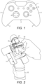
- FIG. 1 shows schematically an example of such a controller.
- the controller of figure 1 comprises a sculpted casing 1.
- the side edges 2 of the casing are curved so as to fit naturally into the palms of both of a user's hands at the same time.
- the lateral portions 3 of the casing extend rearwardly beyond the central portion 4 of the casing. This allows the more ulnar of the user's fingers to extend around the rear portions, helping the user to hold the device securely.
- the central part 4 of the casing carries a number of input buttons 5 which can be accessed by the thumbs of a user holding the controller in the normal way.
- controllers of this type are particularly optimised for devices of this type because they could be used continuously for long periods of time.
- a significant factor in the ergonomic design of controllers of this type is that their weight is borne by the hands of the user. This affects the muscle loading in the user's forearms in particular, which influences the shapes that a user will find comfortable and the movements that could cause strain.
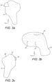
- Figure 2 shows a known controller for a master-slave manipulator having an end effector that comprises a pair of movable jaws.
- the controller has a primary input stem 10.
- the primary input stem constitutes the distal end of a gimbal system 11 which permits the primary input stem to be moved with three degrees of rotational freedom.
- the proximal end of the gimbal system is attached to a base by a parallelogram system, part of which is shown at 12, which permits the primary input stem to be moved with three degrees of translational freedom with respect to the base.
- the primary input stem is provided with two rotatable elements 13, 14 which can be bound by loops 15 to an operator's fingers.
- the operator can move the primary input stem 10 with six degrees of freedom to command a change in position of the end effector, and can move the elements 13, 14 to command opening or closing of the jaws of the end effector.
- One difficulty with an input device of this type is that it can be tiring to use if the user's forearms are not supported. A rest can be provided for the user's forearms, but that restricts the working positions the user can adopt.
- JPH07 246578 A discloses a master-slave robot relates to the master device, and more particularly to an apparatus that facilitates operation of the hand portion of the slave robot.
- the body may be configured to be gripped in normal use by a single hand of the user.
- the drive mechanism comprises motor.
- the motor is arranged for applying force to the trigger.
- the majority of the volume of the motor is located within the grip portion.
- the trigger is arranged to rotate relative to the body about a rotation axis.
- the rotation axis is coincident with the rotation axis of the motor.
- the drive mechanism may terminate in a drive shaft.
- the drive shaft may be coincident with the rotation axis of the trigger.
- the trigger may be carried by the drive shaft.
- the drive mechanism may be configured for applying a torque to the trigger through the drive shaft.
- the grip portion may have an axis of elongation.
- the grip portion may satisfy one or both of the criteria: (i) a minimum circumference perpendicular to that axis of 40mm and (ii) a maximum circumference perpendicular to that axis of 160mm.
- the length of the grip portion along the axis of elongation may be greater than 50mm.
- the user interface device may comprise a position sensor for sensing the position of the trigger relative to the body.
- a robotic manipulator system comprising: a user interface device as set out above; a robot manipulator comprising at least one sensor; and a control unit configured to control the drive unit to provide force feedback by means of the trigger to a user of the user interface device in dependence on a signal received from the sensor.
- the end effector may be an end effector of a surgical instrument carried by the robot manipulator.
- the control unit may be configured to control the motion of a part of the robot manipulator in dependence on input received from the sensor or one of the sensors of the user interface device.
- the control unit may be configured to control the motion of the part of the end effector in dependence on input received from the sensor or one of the sensors of the user interface device.
- the control device 20 of figures 3 and 4 is designed to be held in a user's hand for providing (i) three-dimensional motion input by translation and rotation of the body 21 of the control device and (ii) functional input in dependence on the position of the trigger lever 22 relative to the body of the control device.
- the controller will be described with reference to mutually orthogonal X, Y and Z axes indicated in figured 3a and 3b.
- the X axis is the forward/rearward axis of the controller.
- the Y axis is the left/right axis of the controller.
- the Z axis is the up/down axis of the controller.
- the grip is slimmer than the head.
- the grip In cross-section perpendicular to the extent of the grip, the grip may be generally circular.
- the shape of the grip may be such that in all cross-sections perpendicular to the length of the grip, the the maximum width of the grip in that cross-section is not more than 30% greater than the depth of the grip in that cross-section.
- Additional user interface input devices can be provided on the exterior of the head.
- One or more input devices could be located on or near the trigger 22, for actuation by the user's first finger.
- One or more input devices could be located on or near the trigger 22, for actuation by the user's other fingers. If the grip 24 is configured to be gripped by fewer than three fingers then one or more input devices convenient for those fingers could be located on the lower parts of the head.
- Input devices such as buttons, joysticks and rocker switches may be located on the upper face of the head.
- the rear of the head of the controller is continuous with the rear of the grip.
- the front of the head of the controller extends in front of the most forward part of the grip.
- the head of the controller is attached to the top of the grip. The head does not extend below the top of the grip.
- the grip extends downwardly from the head. Other configurations are possible.
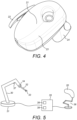
- the controller of figure 3 is intended to be used as an input device for controlling a robot manipulator.
- the robot manipulator may be as shown in figure 5 .
- the robot manipulator of figure 5 has an arm 30 which extends from a base 31.
- the arm is articulated by a series of revolute joints along its length.
- At the distal end of the arm is an instrument 32 which terminates in an end effector.
- the end effector has a pair of opposed jaws 33. These can be moved relative to each other to grip or cut objects located between the jaws.
- the jaws can be driven to move by a drive motor 34 at the distal end of the arm.
- the drive motor is coupled to the jaws by cables extending along the interior of the instrument's shaft.
- the robot is governed by a control unit 35.
- the control unit receives inputs from the controller 20 of figure 3 and from other sources such as motion linkage 36 and arm position/force sensors 37.
- the gearbox may be omitted if the motor itself has a suitable rating.
- the trigger is attached directly to, and carried by, the output shaft of the gearbox or of the motor if the gearbox is omitted.
- the motor may comprise a rotor and a stator.
- the motor may have a rotation axis: i.e. the axis about which the rotor rotates with respect to the stator.
- the rotation axis of the trigger may be parallel with and more preferably coincident with the rotation axis of the motor. That allows for efficient packaging of the motor in the controller, without a need for complex linkages to transfer drive across to the trigger.
- the system may operate in various ways to provide a command signal to the drive motor 34 which drives the jaws.
- a position authority mode the jaws are driven towards a position that maps on to the position of the trigger 22 relative to the head 21, as sensed by position sensor 54.
- a force authority mode the jaws are driven so as to apply a force that maps on to the force applied to the trigger 22 relative to the head 21, as sensed by force sensor 53. Combinations of these modes are also possible.
- motors and gearboxes suitable for the task are 10 to 40mm in diameter. These can readily fit in a grip 24 intended to be fully or partially encircled by the user's fingers.
- the motor and gearbox may comprise much of the weight of the controller. By locating them within the part of the controller that is gripped by the user the loading on the user's wrist and hand to support the controller in a given attitude can be reduced.
- the rotation axis of the trigger should extend through the grip portion.
- the rotation axis of the trigger is substantially parallel with (e.g. within 30°, 20°, 10° or 5° of the principal axis of the grip. This provides flexibility over which motors/gearboxes can be used.
- the grip may be that portion of the controller that can be partially or fully encircled by any of the second to third fingers of a user when the user's hand is in position on the controller.
- the control unit could perform another function: for example, activating a light or a camera.
- the robot may be a surgical robot.
- the instrument could be an industrial or other form of tool.
- the robot could be an industrial robot or a robot for another function.
- the body of the instrument could comprise a coupling for releasable attachment to a robot and an elongate shaft running between the coupling and the end effector.
Landscapes
- Engineering & Computer Science (AREA)
- Physics & Mathematics (AREA)
- General Physics & Mathematics (AREA)
- Automation & Control Theory (AREA)
- Robotics (AREA)
- Mechanical Engineering (AREA)
- Human Computer Interaction (AREA)
- Manipulator (AREA)
- Mechanical Control Devices (AREA)
- User Interface Of Digital Computer (AREA)
Applications Claiming Priority (2)
| Application Number | Priority Date | Filing Date | Title |
|---|---|---|---|
| GB1616086.3A GB2554363B (en) | 2016-09-21 | 2016-09-21 | User interface device |
| PCT/GB2017/052786 WO2018055352A1 (en) | 2016-09-21 | 2017-09-19 | User interface device |
Publications (3)
| Publication Number | Publication Date |
|---|---|
| EP3516475A1 EP3516475A1 (en) | 2019-07-31 |
| EP3516475B1 true EP3516475B1 (en) | 2025-07-09 |
| EP3516475C0 EP3516475C0 (en) | 2025-07-09 |
Family
ID=57288630
Family Applications (1)
| Application Number | Title | Priority Date | Filing Date |
|---|---|---|---|
| EP17777316.5A Active EP3516475B1 (en) | 2016-09-21 | 2017-09-19 | User interface device |
Country Status (6)
| Country | Link |
|---|---|
| US (3) | US10824186B2 (enExample) |
| EP (1) | EP3516475B1 (enExample) |
| JP (1) | JP7233367B2 (enExample) |
| CN (1) | CN109844678B (enExample) |
| GB (1) | GB2554363B (enExample) |
| WO (1) | WO2018055352A1 (enExample) |
Families Citing this family (10)
| Publication number | Priority date | Publication date | Assignee | Title |
|---|---|---|---|---|
| GB2554363B (en) | 2016-09-21 | 2021-12-08 | Cmr Surgical Ltd | User interface device |
| DE102019101646A1 (de) * | 2019-01-23 | 2020-07-23 | HELLA GmbH & Co. KGaA | Pedalemulator für ein Fahrzeug |
| US10838486B2 (en) * | 2019-02-28 | 2020-11-17 | Microsoft Technology Licensing, Llc | Virtual reality controller |
| GB2588176B (en) | 2019-10-11 | 2023-07-26 | Cmr Surgical Ltd | Controlling a surgical instrument |
| USD919009S1 (en) * | 2019-11-21 | 2021-05-11 | Jonathan Blake Buller | Skin cover for a game controller |
| USD902938S1 (en) * | 2019-11-21 | 2020-11-24 | Marketing Instincts Inc. | Skin cover for a game controller |
| USD920341S1 (en) * | 2019-11-21 | 2021-05-25 | Marketing Instincts Inc. | Skin cover set for a game controller |
| USD1035596S1 (en) * | 2021-10-15 | 2024-07-16 | Hyundai Motor Company | Wearable walking assistance robot controller |
| USD1036396S1 (en) * | 2021-10-15 | 2024-07-23 | Hyundai Motor Company | Wearable walking-assistance robot controller |
| EP4440482A4 (en) * | 2021-11-30 | 2025-12-31 | Endoquest Robotics Inc | POSITION CONTROL FOR PATIENT CONSOLE |
Citations (3)
| Publication number | Priority date | Publication date | Assignee | Title |
|---|---|---|---|---|
| JPH07246578A (ja) * | 1994-03-11 | 1995-09-26 | Yaskawa Electric Corp | マスターハンド装置 |
| JP2013034851A (ja) * | 2011-08-04 | 2013-02-21 | Olympus Corp | マニピュレータシステム |
| US20150101440A1 (en) * | 2013-10-11 | 2015-04-16 | Deere & Company | Multifunctional control for a work vehicle |
Family Cites Families (88)
| Publication number | Priority date | Publication date | Assignee | Title |
|---|---|---|---|---|
| US2754505A (en) * | 1953-10-21 | 1956-07-10 | Tactair Inc | Tactile control indicator |
| US4795296A (en) * | 1986-11-17 | 1989-01-03 | California Institute Of Technology | Hand-held robot end effector controller having movement and force control |
| US5116180A (en) * | 1988-07-18 | 1992-05-26 | Spar Aerospace Limited | Human-in-the-loop machine control loop |
| US6390370B1 (en) * | 1990-11-15 | 2002-05-21 | Symbol Technologies, Inc. | Light beam scanning pen, scan module for the device and method of utilization |
| US5389865A (en) * | 1992-12-02 | 1995-02-14 | Cybernet Systems Corporation | Method and system for providing a tactile virtual reality and manipulator defining an interface device therefor |
| US5731804A (en) * | 1995-01-18 | 1998-03-24 | Immersion Human Interface Corp. | Method and apparatus for providing high bandwidth, low noise mechanical I/O for computer systems |
| JP2698320B2 (ja) * | 1993-08-31 | 1998-01-19 | 日本電信電話株式会社 | 常装着型入力システム、常装着型意図伝達システム、常装着型音楽用キーボードシステム及び常装着型点字入出力システム |
| US20050192727A1 (en) * | 1994-05-09 | 2005-09-01 | Automotive Technologies International Inc. | Sensor Assemblies |
| US6256011B1 (en) * | 1997-12-03 | 2001-07-03 | Immersion Corporation | Multi-function control device with force feedback |
| US6184868B1 (en) * | 1998-09-17 | 2001-02-06 | Immersion Corp. | Haptic feedback control devices |
| US6951535B2 (en) * | 2002-01-16 | 2005-10-04 | Intuitive Surgical, Inc. | Tele-medicine system that transmits an entire state of a subsystem |
| US6536298B1 (en) * | 2000-06-30 | 2003-03-25 | Caterpillar Inc | Modular joystick |
| US7877243B2 (en) * | 2001-07-16 | 2011-01-25 | Immersion Corporation | Pivotable computer interface |
| KR100507554B1 (ko) * | 2003-05-21 | 2005-08-17 | 한국과학기술연구원 | 병렬형 햅틱 조이스틱 시스템 |
| US20050252329A1 (en) * | 2004-05-13 | 2005-11-17 | Jean-Guy Demers | Haptic mechanism |
| CN100447031C (zh) * | 2004-06-14 | 2008-12-31 | 李昌学 | 操纵杆装置 |
| US7089099B2 (en) * | 2004-07-30 | 2006-08-08 | Automotive Technologies International, Inc. | Sensor assemblies |
| DE602005013571D1 (de) * | 2004-12-14 | 2009-05-07 | Howard Mark Anthony | Detektor |
| US7642741B2 (en) * | 2005-04-27 | 2010-01-05 | Sidman Adam D | Handheld platform stabilization system employing distributed rotation sensors |
| JP2006334695A (ja) * | 2005-05-31 | 2006-12-14 | Kyoto Univ | 遠隔操縦装置 |
| JP2009527366A (ja) * | 2006-02-24 | 2009-07-30 | フェルロボティクス コンプライアント ロボット テクノロジー ゲーエムベーハー | ロボットアーム |
| EP2018721A4 (en) * | 2006-05-12 | 2012-08-08 | Irobot Corp | METHOD AND DEVICE FOR CONTROLLING A REMOTE VEHICLE |
| DE602006017820D1 (de) * | 2006-07-03 | 2010-12-09 | Force Dimension S A R L | Schwerkraftausgleich für eine haptische Vorrichtung |
| EP2104455A2 (en) * | 2006-09-25 | 2009-09-30 | Koninklijke Philips Electronics N.V. | Haptic feedback medical scanning methods and systems |
| US9174344B2 (en) * | 2006-12-19 | 2015-11-03 | Deakin University | Method and apparatus for haptic control |
| US8682502B2 (en) * | 2007-03-28 | 2014-03-25 | Irobot Corporation | Remote vehicle control system and method |
| US7808235B2 (en) * | 2007-11-29 | 2010-10-05 | Rockwell Automation Technologies, Inc. | Apparatus and methods for proximity sensing circuitry |
| US8727966B2 (en) * | 2008-03-31 | 2014-05-20 | Intuitive Surgical Operations, Inc. | Endoscope with rotationally deployed arms |
| US8340819B2 (en) * | 2008-09-18 | 2012-12-25 | Intouch Technologies, Inc. | Mobile videoconferencing robot system with network adaptive driving |
| US7843277B2 (en) * | 2008-12-16 | 2010-11-30 | Immersion Corporation | Haptic feedback generation based on resonant frequency |
| US8374723B2 (en) * | 2008-12-31 | 2013-02-12 | Intuitive Surgical Operations, Inc. | Obtaining force information in a minimally invasive surgical procedure |
| US8594841B2 (en) * | 2008-12-31 | 2013-11-26 | Intuitive Surgical Operations, Inc. | Visual force feedback in a minimally invasive surgical procedure |
| US8418073B2 (en) * | 2009-03-09 | 2013-04-09 | Intuitive Surgical Operations, Inc. | User interfaces for electrosurgical tools in robotic surgical systems |
| US8473101B2 (en) * | 2009-08-21 | 2013-06-25 | Harris Corporation | Coordinated action robotic system and related methods |
| US9844447B2 (en) * | 2010-04-09 | 2017-12-19 | Deka Products Limited Partnership | System and apparatus for robotic device and methods of using thereof |
| US9782214B2 (en) * | 2010-11-05 | 2017-10-10 | Ethicon Llc | Surgical instrument with sensor and powered control |
| US8606403B2 (en) * | 2010-12-14 | 2013-12-10 | Harris Corporation | Haptic interface handle with force-indicating trigger mechanism |
| US9119655B2 (en) * | 2012-08-03 | 2015-09-01 | Stryker Corporation | Surgical manipulator capable of controlling a surgical instrument in multiple modes |
| US8918215B2 (en) * | 2011-01-19 | 2014-12-23 | Harris Corporation | Telematic interface with control signal scaling based on force sensor feedback |
| US8918214B2 (en) * | 2011-01-19 | 2014-12-23 | Harris Corporation | Telematic interface with directional translation |
| US9791886B2 (en) * | 2011-05-12 | 2017-10-17 | Bombardier Inc. | Controller |
| US9566710B2 (en) * | 2011-06-02 | 2017-02-14 | Brain Corporation | Apparatus and methods for operating robotic devices using selective state space training |
| US20150127154A1 (en) * | 2011-06-02 | 2015-05-07 | Brain Corporation | Reduced degree of freedom robotic controller apparatus and methods |
| EP2740434A4 (en) * | 2011-08-04 | 2015-03-18 | Olympus Corp | MEDICAL MANIPULATOR AND CONTROL METHOD THEREOF |
| US9272061B2 (en) | 2012-02-07 | 2016-03-01 | Estes Design And Manufacturing, Inc. | Sterilization tray for instruments |
| US20130293362A1 (en) * | 2012-05-03 | 2013-11-07 | The Methodist Hospital Research Institute | Multi-degrees-of-freedom hand controller |
| US9317123B2 (en) * | 2012-06-13 | 2016-04-19 | University Of Utah Research Foundation | Skin stretch feedback devices, systems, and methods |
| US9092698B2 (en) * | 2012-06-21 | 2015-07-28 | Rethink Robotics, Inc. | Vision-guided robots and methods of training them |
| US9820768B2 (en) * | 2012-06-29 | 2017-11-21 | Ethicon Llc | Ultrasonic surgical instruments with control mechanisms |
| US9283045B2 (en) * | 2012-06-29 | 2016-03-15 | Ethicon Endo-Surgery, Llc | Surgical instruments with fluid management system |
| CA2879414A1 (en) * | 2012-08-03 | 2014-02-06 | Stryker Corporation | Systems and methods for robotic surgery |
| US11351042B2 (en) * | 2012-08-12 | 2022-06-07 | 5Th Element Limited | Automated hand |
| US9095367B2 (en) * | 2012-10-22 | 2015-08-04 | Ethicon Endo-Surgery, Inc. | Flexible harmonic waveguides/blades for surgical instruments |
| US10201365B2 (en) * | 2012-10-22 | 2019-02-12 | Ethicon Llc | Surgeon feedback sensing and display methods |
| WO2014120984A2 (en) * | 2013-01-30 | 2014-08-07 | David Paul Smith | Operator controlled electrical output signal device with variable feel and hold feedback and automated calibration and learnable performance optimization |
| MX352726B (es) * | 2013-02-28 | 2017-12-06 | Facebook Inc | Controlador de retroalimentación de fuerza exoesqueletal modular. |
| RU2669463C2 (ru) * | 2013-03-01 | 2018-10-11 | Этикон Эндо-Серджери, Инк. | Хирургический инструмент с мягким упором |
| US9404727B2 (en) * | 2013-09-16 | 2016-08-02 | Texas Instruments Incorporated | Inductive position sensing with single channel interface to multiple resonant sensors |
| FR3011815B1 (fr) * | 2013-10-15 | 2016-01-08 | Sagem Defense Securite | Dispositif de commande de vol d'un aeronef |
| JP6358463B2 (ja) * | 2013-11-13 | 2018-07-18 | パナソニックIpマネジメント株式会社 | マスタースレーブ装置用マスター装置及びその制御方法、及び、マスタースレーブ装置 |
| US9539020B2 (en) * | 2013-12-27 | 2017-01-10 | Ethicon Endo-Surgery, Llc | Coupling features for ultrasonic surgical instrument |
| JP2017506169A (ja) * | 2014-02-20 | 2017-03-02 | マーク オレイニク | ロボット調理キッチン内の食品調製のための方法及びシステム |
| US9579797B2 (en) * | 2014-04-10 | 2017-02-28 | Quanser Consulting Inc. | Robotic systems and methods of operating robotic systems |
| US20170007337A1 (en) * | 2014-07-01 | 2017-01-12 | Auris Surgical Robotics, Inc. | Driver-mounted torque sensing mechanism |
| US10518409B2 (en) * | 2014-09-02 | 2019-12-31 | Mark Oleynik | Robotic manipulation methods and systems for executing a domain-specific application in an instrumented environment with electronic minimanipulation libraries |
| GB2532069A (en) * | 2014-11-07 | 2016-05-11 | Weatherstone Paul | Game controller |
| WO2016077531A1 (en) * | 2014-11-13 | 2016-05-19 | Intuitive Surgical Operations, Inc. | Integrated user environments |
| US10126884B2 (en) * | 2014-12-22 | 2018-11-13 | Synaptics Incorporated | Asynchronous interference detection in a capacitive sensing system |
| US10232254B2 (en) * | 2015-04-30 | 2019-03-19 | Microsoft Technology Licensing, Llc | Game controller with removable paddle accessory |
| US10232255B2 (en) * | 2015-04-30 | 2019-03-19 | Microsoft Technology Licensing, Llc | Paddle accessory for a game controller |
| US11020859B2 (en) * | 2015-05-01 | 2021-06-01 | Transportation Ip Holdings, Llc | Integrated robotic system and method for autonomous vehicle maintenance |
| US9889566B2 (en) * | 2015-05-01 | 2018-02-13 | General Electric Company | Systems and methods for control of robotic manipulation |
| US10525600B2 (en) * | 2015-06-03 | 2020-01-07 | L3Harris Technologies, Inc. | Robotic system with haptic cutting tool |
| US10427035B2 (en) * | 2015-06-09 | 2019-10-01 | Microsoft Technology Licensing, Llc | Game controller with removable trigger accessory |
| BR112018000607A2 (pt) * | 2015-08-03 | 2018-09-11 | Halliburton Energy Services Inc | sistema de telemetria eletromagnética para uso com equipamentos de poço e método para comunicar com um transceptor de fundo de poço |
| US10199850B2 (en) * | 2015-09-16 | 2019-02-05 | Energous Corporation | Systems and methods for wirelessly transmitting power from a transmitter to a receiver by determining refined locations of the receiver in a segmented transmission field associated with the transmitter |
| US10085810B2 (en) * | 2015-10-02 | 2018-10-02 | Ethicon Llc | User input device for robotic surgical system |
| ITUB20154977A1 (it) * | 2015-10-16 | 2017-04-16 | Medical Microinstruments S R L | Strumento medicale e metodo di fabbricazione di detto strumento medicale |
| ITUB20155057A1 (it) * | 2015-10-16 | 2017-04-16 | Medical Microinstruments S R L | Assieme robotico di chirurgia |
| AU2016365200B2 (en) * | 2015-11-30 | 2021-10-28 | Stryker Corporation | Surgical instrument with telescoping nose mechanism |
| US10562191B2 (en) * | 2015-12-29 | 2020-02-18 | Robomotive Laboratories LLC | Method of controlling devices with sensation of applied force |
| US10434659B2 (en) * | 2016-03-02 | 2019-10-08 | Kindred Systems Inc. | Systems, devices, articles, and methods for user input |
| GB2554363B (en) * | 2016-09-21 | 2021-12-08 | Cmr Surgical Ltd | User interface device |
| US11230000B2 (en) * | 2017-03-20 | 2022-01-25 | Georgia Tech Research Corporation | Mobile manipulation device |
| US10732714B2 (en) * | 2017-05-08 | 2020-08-04 | Cirrus Logic, Inc. | Integrated haptic system |
| US10514545B2 (en) * | 2017-12-08 | 2019-12-24 | Facebook Technologies, Llc | Selective tracking of a head-mounted display |
| US11135031B2 (en) * | 2018-06-15 | 2021-10-05 | Verb Surgical Inc. | User interface device having grip linkages |
| US11599107B2 (en) * | 2019-12-09 | 2023-03-07 | Fluidity Technologies Inc. | Apparatus, methods and systems for remote or onboard control of flights |
-
2016
- 2016-09-21 GB GB1616086.3A patent/GB2554363B/en active Active
-
2017
- 2017-09-19 JP JP2019536337A patent/JP7233367B2/ja active Active
- 2017-09-19 CN CN201780057639.5A patent/CN109844678B/zh active Active
- 2017-09-19 EP EP17777316.5A patent/EP3516475B1/en active Active
- 2017-09-19 US US16/334,873 patent/US10824186B2/en active Active
- 2017-09-19 WO PCT/GB2017/052786 patent/WO2018055352A1/en not_active Ceased
-
2020
- 2020-10-01 US US17/060,668 patent/US11366484B2/en active Active
-
2022
- 2022-05-06 US US17/738,823 patent/US11803206B2/en active Active
Patent Citations (3)
| Publication number | Priority date | Publication date | Assignee | Title |
|---|---|---|---|---|
| JPH07246578A (ja) * | 1994-03-11 | 1995-09-26 | Yaskawa Electric Corp | マスターハンド装置 |
| JP2013034851A (ja) * | 2011-08-04 | 2013-02-21 | Olympus Corp | マニピュレータシステム |
| US20150101440A1 (en) * | 2013-10-11 | 2015-04-16 | Deere & Company | Multifunctional control for a work vehicle |
Also Published As
| Publication number | Publication date |
|---|---|
| CN109844678A (zh) | 2019-06-04 |
| WO2018055352A1 (en) | 2018-03-29 |
| US11366484B2 (en) | 2022-06-21 |
| US20220261029A1 (en) | 2022-08-18 |
| US11803206B2 (en) | 2023-10-31 |
| GB201616086D0 (en) | 2016-11-02 |
| GB2554363A (en) | 2018-04-04 |
| JP2019533267A (ja) | 2019-11-14 |
| JP7233367B2 (ja) | 2023-03-06 |
| EP3516475A1 (en) | 2019-07-31 |
| CN109844678B (zh) | 2021-03-19 |
| GB2554363B (en) | 2021-12-08 |
| US20200019205A1 (en) | 2020-01-16 |
| EP3516475C0 (en) | 2025-07-09 |
| US20210018951A1 (en) | 2021-01-21 |
| US10824186B2 (en) | 2020-11-03 |
Similar Documents
| Publication | Publication Date | Title |
|---|---|---|
| US11803206B2 (en) | User interface device | |
| EP2744629B1 (en) | Haptic manipulation system for wheelchairs | |
| EP2465650B1 (en) | Haptic interface handle with force-indicating trigger mechanism | |
| WO2017033381A1 (ja) | ロボットシステム | |
| WO2019099584A1 (en) | Master control device and methods therefor | |
| US10882191B2 (en) | Robotic system with haptic cutting tool | |
| AU2022224785B2 (en) | Camera Control | |
| GB2596658A (en) | User interface device | |
| JPH05228854A (ja) | 7自由度アーム制御方式 | |
| KR101836499B1 (ko) | 햅틱형 로봇 핸들시스템 | |
| GB2606672A (en) | Camera control | |
| GB2605090A (en) | Camera control | |
| GB2605091A (en) | Camera control |
Legal Events
| Date | Code | Title | Description |
|---|---|---|---|
| STAA | Information on the status of an ep patent application or granted ep patent |
Free format text: STATUS: UNKNOWN |
|
| STAA | Information on the status of an ep patent application or granted ep patent |
Free format text: STATUS: THE INTERNATIONAL PUBLICATION HAS BEEN MADE |
|
| PUAI | Public reference made under article 153(3) epc to a published international application that has entered the european phase |
Free format text: ORIGINAL CODE: 0009012 |
|
| STAA | Information on the status of an ep patent application or granted ep patent |
Free format text: STATUS: REQUEST FOR EXAMINATION WAS MADE |
|
| 17P | Request for examination filed |
Effective date: 20190408 |
|
| AK | Designated contracting states |
Kind code of ref document: A1 Designated state(s): AL AT BE BG CH CY CZ DE DK EE ES FI FR GB GR HR HU IE IS IT LI LT LU LV MC MK MT NL NO PL PT RO RS SE SI SK SM TR |
|
| AX | Request for extension of the european patent |
Extension state: BA ME |
|
| DAV | Request for validation of the european patent (deleted) | ||
| DAX | Request for extension of the european patent (deleted) | ||
| RAP1 | Party data changed (applicant data changed or rights of an application transferred) |
Owner name: CMR SURGICAL LIMITED |
|
| STAA | Information on the status of an ep patent application or granted ep patent |
Free format text: STATUS: EXAMINATION IS IN PROGRESS |
|
| 17Q | First examination report despatched |
Effective date: 20220310 |
|
| GRAP | Despatch of communication of intention to grant a patent |
Free format text: ORIGINAL CODE: EPIDOSNIGR1 |
|
| STAA | Information on the status of an ep patent application or granted ep patent |
Free format text: STATUS: GRANT OF PATENT IS INTENDED |
|
| RIC1 | Information provided on ipc code assigned before grant |
Ipc: G05G 5/03 20080401ALI20250203BHEP Ipc: G05G 9/047 20060101AFI20250203BHEP |
|
| INTG | Intention to grant announced |
Effective date: 20250220 |
|
| RIN1 | Information on inventor provided before grant (corrected) |
Inventor name: CUTHBERTSON, REBECCA ANNE |
|
| GRAS | Grant fee paid |
Free format text: ORIGINAL CODE: EPIDOSNIGR3 |
|
| GRAA | (expected) grant |
Free format text: ORIGINAL CODE: 0009210 |
|
| STAA | Information on the status of an ep patent application or granted ep patent |
Free format text: STATUS: THE PATENT HAS BEEN GRANTED |
|
| AK | Designated contracting states |
Kind code of ref document: B1 Designated state(s): AL AT BE BG CH CY CZ DE DK EE ES FI FR GB GR HR HU IE IS IT LI LT LU LV MC MK MT NL NO PL PT RO RS SE SI SK SM TR |
|
| REG | Reference to a national code |
Ref country code: GB Ref legal event code: FG4D |
|
| REG | Reference to a national code |
Ref country code: CH Ref legal event code: EP |
|
| REG | Reference to a national code |
Ref country code: IE Ref legal event code: FG4D |
|
| REG | Reference to a national code |
Ref country code: DE Ref legal event code: R096 Ref document number: 602017090463 Country of ref document: DE |
|
| U01 | Request for unitary effect filed |
Effective date: 20250807 |
|
| U07 | Unitary effect registered |
Designated state(s): AT BE BG DE DK EE FI FR IT LT LU LV MT NL PT RO SE SI Effective date: 20250820 |
|
| PGFP | Annual fee paid to national office [announced via postgrant information from national office to epo] |
Ref country code: GB Payment date: 20250911 Year of fee payment: 9 |
|
| U20 | Renewal fee for the european patent with unitary effect paid |
Year of fee payment: 9 Effective date: 20250911 |
|
| PG25 | Lapsed in a contracting state [announced via postgrant information from national office to epo] |
Ref country code: IS Free format text: LAPSE BECAUSE OF FAILURE TO SUBMIT A TRANSLATION OF THE DESCRIPTION OR TO PAY THE FEE WITHIN THE PRESCRIBED TIME-LIMIT Effective date: 20251109 |
|
| PG25 | Lapsed in a contracting state [announced via postgrant information from national office to epo] |
Ref country code: NO Free format text: LAPSE BECAUSE OF FAILURE TO SUBMIT A TRANSLATION OF THE DESCRIPTION OR TO PAY THE FEE WITHIN THE PRESCRIBED TIME-LIMIT Effective date: 20251009 |
|
| PG25 | Lapsed in a contracting state [announced via postgrant information from national office to epo] |
Ref country code: HR Free format text: LAPSE BECAUSE OF FAILURE TO SUBMIT A TRANSLATION OF THE DESCRIPTION OR TO PAY THE FEE WITHIN THE PRESCRIBED TIME-LIMIT Effective date: 20250709 |
|
| PG25 | Lapsed in a contracting state [announced via postgrant information from national office to epo] |
Ref country code: GR Free format text: LAPSE BECAUSE OF FAILURE TO SUBMIT A TRANSLATION OF THE DESCRIPTION OR TO PAY THE FEE WITHIN THE PRESCRIBED TIME-LIMIT Effective date: 20251010 |
|
| PG25 | Lapsed in a contracting state [announced via postgrant information from national office to epo] |
Ref country code: PL Free format text: LAPSE BECAUSE OF FAILURE TO SUBMIT A TRANSLATION OF THE DESCRIPTION OR TO PAY THE FEE WITHIN THE PRESCRIBED TIME-LIMIT Effective date: 20250709 |
|
| PG25 | Lapsed in a contracting state [announced via postgrant information from national office to epo] |
Ref country code: RS Free format text: LAPSE BECAUSE OF FAILURE TO SUBMIT A TRANSLATION OF THE DESCRIPTION OR TO PAY THE FEE WITHIN THE PRESCRIBED TIME-LIMIT Effective date: 20251009 |
|
| PG25 | Lapsed in a contracting state [announced via postgrant information from national office to epo] |
Ref country code: ES Free format text: LAPSE BECAUSE OF FAILURE TO SUBMIT A TRANSLATION OF THE DESCRIPTION OR TO PAY THE FEE WITHIN THE PRESCRIBED TIME-LIMIT Effective date: 20250709 |
|
| PG25 | Lapsed in a contracting state [announced via postgrant information from national office to epo] |
Ref country code: SM Free format text: LAPSE BECAUSE OF FAILURE TO SUBMIT A TRANSLATION OF THE DESCRIPTION OR TO PAY THE FEE WITHIN THE PRESCRIBED TIME-LIMIT Effective date: 20250709 |
|
| PG25 | Lapsed in a contracting state [announced via postgrant information from national office to epo] |
Ref country code: CZ Free format text: LAPSE BECAUSE OF FAILURE TO SUBMIT A TRANSLATION OF THE DESCRIPTION OR TO PAY THE FEE WITHIN THE PRESCRIBED TIME-LIMIT Effective date: 20250709 |
|
| PG25 | Lapsed in a contracting state [announced via postgrant information from national office to epo] |
Ref country code: SK Free format text: LAPSE BECAUSE OF FAILURE TO SUBMIT A TRANSLATION OF THE DESCRIPTION OR TO PAY THE FEE WITHIN THE PRESCRIBED TIME-LIMIT Effective date: 20250709 |