EP3516202B1 - Injector sleeve assembly and method for field repair procedure - Google Patents
Injector sleeve assembly and method for field repair procedure Download PDFInfo
- Publication number
- EP3516202B1 EP3516202B1 EP17863497.8A EP17863497A EP3516202B1 EP 3516202 B1 EP3516202 B1 EP 3516202B1 EP 17863497 A EP17863497 A EP 17863497A EP 3516202 B1 EP3516202 B1 EP 3516202B1
- Authority
- EP
- European Patent Office
- Prior art keywords
- retaining ring
- fuel injector
- sleeve
- injector sleeve
- insertion tool
- Prior art date
- Legal status (The legal status is an assumption and is not a legal conclusion. Google has not performed a legal analysis and makes no representation as to the accuracy of the status listed.)
- Active
Links
Images


Classifications
-
- B—PERFORMING OPERATIONS; TRANSPORTING
- B25—HAND TOOLS; PORTABLE POWER-DRIVEN TOOLS; MANIPULATORS
- B25B—TOOLS OR BENCH DEVICES NOT OTHERWISE PROVIDED FOR, FOR FASTENING, CONNECTING, DISENGAGING, OR HOLDING
- B25B23/00—Details of, or accessories for, spanners, wrenches, screwdrivers
- B25B23/0078—Reaction arms
-
- B—PERFORMING OPERATIONS; TRANSPORTING
- B25—HAND TOOLS; PORTABLE POWER-DRIVEN TOOLS; MANIPULATORS
- B25B—TOOLS OR BENCH DEVICES NOT OTHERWISE PROVIDED FOR, FOR FASTENING, CONNECTING, DISENGAGING, OR HOLDING
- B25B27/00—Hand tools, specially adapted for fitting together or separating parts or objects whether or not involving some deformation, not otherwise provided for
- B25B27/0028—Tools for removing or installing seals
-
- F—MECHANICAL ENGINEERING; LIGHTING; HEATING; WEAPONS; BLASTING
- F02—COMBUSTION ENGINES; HOT-GAS OR COMBUSTION-PRODUCT ENGINE PLANTS
- F02M—SUPPLYING COMBUSTION ENGINES IN GENERAL WITH COMBUSTIBLE MIXTURES OR CONSTITUENTS THEREOF
- F02M53/00—Fuel-injection apparatus characterised by having heating, cooling or thermally-insulating means
- F02M53/04—Injectors with heating, cooling, or thermally-insulating means
- F02M53/043—Injectors with heating, cooling, or thermally-insulating means with cooling means other than air cooling
-
- F—MECHANICAL ENGINEERING; LIGHTING; HEATING; WEAPONS; BLASTING
- F02—COMBUSTION ENGINES; HOT-GAS OR COMBUSTION-PRODUCT ENGINE PLANTS
- F02M—SUPPLYING COMBUSTION ENGINES IN GENERAL WITH COMBUSTIBLE MIXTURES OR CONSTITUENTS THEREOF
- F02M61/00—Fuel-injectors not provided for in groups F02M39/00 - F02M57/00 or F02M67/00
- F02M61/14—Arrangements of injectors with respect to engines; Mounting of injectors
-
- B—PERFORMING OPERATIONS; TRANSPORTING
- B23—MACHINE TOOLS; METAL-WORKING NOT OTHERWISE PROVIDED FOR
- B23P—METAL-WORKING NOT OTHERWISE PROVIDED FOR; COMBINED OPERATIONS; UNIVERSAL MACHINE TOOLS
- B23P6/00—Restoring or reconditioning objects
-
- B—PERFORMING OPERATIONS; TRANSPORTING
- B23—MACHINE TOOLS; METAL-WORKING NOT OTHERWISE PROVIDED FOR
- B23P—METAL-WORKING NOT OTHERWISE PROVIDED FOR; COMBINED OPERATIONS; UNIVERSAL MACHINE TOOLS
- B23P6/00—Restoring or reconditioning objects
- B23P6/04—Repairing fractures or cracked metal parts or products, e.g. castings
-
- F—MECHANICAL ENGINEERING; LIGHTING; HEATING; WEAPONS; BLASTING
- F02—COMBUSTION ENGINES; HOT-GAS OR COMBUSTION-PRODUCT ENGINE PLANTS
- F02M—SUPPLYING COMBUSTION ENGINES IN GENERAL WITH COMBUSTIBLE MIXTURES OR CONSTITUENTS THEREOF
- F02M2200/00—Details of fuel-injection apparatus, not otherwise provided for
- F02M2200/85—Mounting of fuel injection apparatus
- F02M2200/858—Mounting of fuel injection apparatus sealing arrangements between injector and engine
Definitions
- the present invention relates generally to fuel injector sleeve seals and more particularly to structure and methods for in-field repair of a fuel injector sleeve leak at an upper seal location.
- Internal combustion engines having fuel injectors typically locate the injectors in bores formed in the cylinder head.
- An injector sleeve is normally inserted in the injector bore, and the injector is received within the sleeve.
- One or more coolant chambers are formed in the cylinder head and separated from the injector by the injector sleeve.
- a seal is typically formed between the sleeve and the cylinder bore above and below the coolant chamber. In some cases, one or both of the seals are formed of an elastomeric material.
- a sealing compound is typically required and used in dry, pre-applied form or by using additional sealant at the sleeve-to-cylinder head interface.
- This approach is also expensive, time consuming and complicated, and requires the removal of the entire injector sleeve. Accordingly, it is desirable to provide an inexpensive, quick and simple approach to be used in the field for repairing a leaking upper seal between an injector sleeve and the injector bore.
- US Pub.No. 2011067653 describes an injector seal assembly and method of sealing a coolant passage from an injector.
- the seal assembly includes a sealing sleeve sized and dimensioned to slip fit into an injector mounting bore and a retaining ring sized and dimensioned to be axially inserted into the sleeve.
- the ring contacts the sleeve and applies a radial force sufficient to create an interference fit and to move or yield an interface portion of the sleeve radially outward into sealing abutment against a wall forming the injector mounting bore to create a secure and reliable annular fluid seal.
- the present disclosure provides a method of repairing a seal between a fuel injector sleeve and fuel injector bore, comprising: removing a fuel injector from the fuel injector sleeve; the fuel injector sleeve having an upper portion comprising an annular groove for receiving a seal ring; installing a retaining ring in the fuel injector bore, the retaining ring having a side wall with an outer surface having a curved portion adjacent at least one edge to guide the retaining ring into the fuel injector bore, the retaining ring further having an outer diameter that is larger than an inner diameter of the fuel injector sleeve at a location adjacent the seal such that when the retaining ring is in an installed position, the fuel injector sleeve is deformed outwardly toward the fuel injector bore, thereby repairing the seal; and replacing the fuel injector.
- installing the retaining ring comprises placing the retaining ring on an insertion tool, inserting the insertion tool into the fuel injector sleeve, and using the insertion tool to force the retaining ring into its installed position.
- using the insertion tool to force the retaining ring into its installed position comprises rotating a drive rod of the insertion tool to cause an engagement boss of the insertion tool to force the retaining ring into the fuel injector sleeve until a stop nut mounted to the drive rod engages an upper surface of the insertion tool.
- installing the retaining ring comprises attaching the insertion tool to a cylinder head forming the fuel injector bore.
- attaching the insertion tool to the cylinder head comprises positioning a mounting bore of a handle body of the insertion tool in alignment with an opening in the cylinder head adjacent the fuel injector bore and threading a cap screw through the mounting bore into the opening.
- attaching the insertion tool to the cylinder head comprises threading a bolt through an opening in an extension of a handle body of the insertion tool, thereby causing a foot connected to the bolt to engage a surface of the cylinder head.
- the retaining ring comprises an outer surface including at least one of an upper curved portion and a lower curved portion, and a central portion having a curvature that is less pronounced than upper curved portion and lower curved portion such that the outer surface resembles a barrel.
- installing the retaining ring comprises centering the retaining ring in the fuel injector sleeve by the at least one of an upper curved portion and a lower curved portion of the retaining ring.
- the upper curved portion of the retaining ring is adjacent a substantially flat upper edge of the retaining ring and the lower curved portion of the retaining ring is adjacent a substantially flat lower edge of the retaining ring.
- the outer diameter of the retaining ring is larger than the inner diameter of the fuel injector sleeve by a distance in the range of 0.3 to 0.6 mm. In a variant of this aspect, the outer diameter of the retaining ring is larger than the inner diameter of the fuel injector sleeve by a distance in the range of 0.35to 0.5 mm.
- the present disclosure provides a retaining ring and a fuel injector sleeve, the retaining ring configured for in-field repair of a fuel injector sleeve upper seal leak, comprising: the fuel injector sleeve having an upper portion comprising an annular groove for receiving a seal ring, the retaining ring comprising a circular side wall comprising a barrel-shaped outer surface and a substantially cylindrical inner surface; wherein the outer surface comprises a lower curved portion and a central portion having a curvature that is less pronounced than the lower curved portion; and wherein the lower curved portion is configured to guide the retaining ring into the fuel injector sleeve and the circular side wall has an outer diameter at the central portion that is larger than an inner diameter of the fuel injector sleeve at a location of the upper seal leak such that the retaining ring forces the fuel injector sleeve outwardly at the location of the upper seal leak as the retaining ring is moved into an
- the circular side wall comprises an upper edge between the inner surface and the outer surface, and a lower edge between the inner surface and the outer surface.
- the lower curved portion is adjacent the lower edge of the circular side wall.
- the circular side wall defines a central opening having a substantially constant diameter between the upper edge and the lower edge of the circular side wall.
- the outer surface further comprises an upper curved portion adjacent the upper edge.
- the outer diameter at the central portion of the retaining ring is larger than the inner diameter of the fuel injector sleeve by a distance in the range of 0.3 to 0.6 mm.
- the outer diameter at the central portion of the retaining ring is larger than the inner diameter of the fuel injector sleeve by a distance in the range of 0.35 to 0.5 mm.
- the present disclosure provides a system for in-field repair of a fuel injector sleeve upper seal leak, comprising: a retaining ring comprising a circular side wall having an outer surface and defining a central opening, the outer surface comprising a lower portion configured to guide the retaining ring into the fuel injector sleeve and a central portion having a diameter that is larger than an inner diameter of the fuel injector sleeve adjacent the upper seal leak; and an insertion tool comprising a handle, a threaded drive rod coupled to the handle and a guide end coupled to the threaded drive rod and configured to extend into the fuel injector sleeve, the handle including a mounting bore configured to receive a cap screw for mounting the insertion tool to a cylinder head of an engine, the threaded drive rod including a drive head, and the guide end being configured to extend through the central opening of the retaining ring and having an engagement boss that forces the retaining ring into an installed position in the fuel injector sleeve
- the central portion of the outer surface has a curvature that is less pronounced than a curvature of the lower portion.
- the retaining ring further comprises an upper portion having a curvature that is more pronounced than the curvature of the central portion such that the outer surface resembles a barrel.
- the insertion tool handle includes an extension opposite the mounting bore, the extension including an opening for receiving a bolt coupled to a foot configured to engage the cylinder head.
- the modifier "about” used in connection with a quantity is inclusive of the stated value and has the meaning dictated by the context (for example, it includes at least the degree of error associated with the measurement of the particular quantity).
- the modifier "about” should also be considered as disclosing the range defined by the absolute values of the two endpoints. For example, the range “from about 2 to about 4" also discloses the range “from 2 to 4.”
- the present disclosure provides a field repair procedure and system that permits repair of a leaking elastomeric (or other material) upper injector seal without the need to remove the cylinder head or injector sleeve.
- a retaining ring having a barrel shaped outer contour which is substantially self-centering and self-guiding is installed into the injector sleeve in-situ and sized with an outer diameter which is larger than the inner diameter of the injector sleeve to cause an interference fit that re-establishes sealing capability after a leak has developed.
- Installation of the retainer ring may be accomplished using a simple pressing or impact tool which extends into the cylinder bore to seat to the proper depth. Using the procedure and system described herein, a seal may be repaired for a small fraction of the cost with greatly reduced engine downtime.
- Assembly 10 generally includes a fuel injector 12 disposed within an injector sleeve 14, which in turn is disposed within an injector bore 16 formed in a cylinder head 18.
- Cylinder head 18 includes a coolant passage 20 in fluid communication with injector bore 16.
- a retaining ring 22 may be positioned in the lower portion of sleeve 14 to provide a lower seal of coolant passage 20 at an interface portion 24 having a bore sealing surface 26 as described in U.S. Patent No. 8,230,808 , entitled INJECTOR SEAL ASSEMBLY AND METHOD OF SEALING A COOLANT PASSAGE FROM AN INJECTOR, which is also owned by the present assignee.
- Sleeve 14 generally has a side wall 29 with a cylindrical or tubular shape formed of appropriate material to be slip fit into place in bore 16.
- sleeve 14 typically includes an annular groove 28 for receiving a seal ring 30 which may be made of an elastomeric material.
- seal ring 30 and annular groove 28 may be omitted, or replaced with a series of shallow grooves to enhance plasticity of the sleeve outer surface.
- the sleeve 14 is sized with an appropriate diameter to create a close fit, and is then typically rolled with a conventional rolling device to form a seal with bore 16 and create a slight locking feature of sleeve material into the coolant passage. In this manner, coolant passage 20 is separated from the annular chamber 32 between injector 12 and sleeve 14, which usually is filled with low pressure fuel.
- the upper end of sleeve 14 has a burnished area 34.
- seal ring 30 may degrade and leak. As indicated above, replacement/repair of seal ring 30 using conventional techniques may be expensive, time consuming and complicated.
- the present disclosure provides a technique and system for repairing the seal provided by seal ring 30 in the field without removing sleeve 14 and without replacing cylinder head 18.
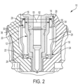
- a retaining ring 36 is provided to repair the seal provided by seal ring 30. As shown generally in FIG. 2 , retaining ring 36 is positioned between fuel injector 12 and injector sleeve 14 to press outwardly against sleeve 14 to repair the seal earlier provided by the damaged/degraded seal ring 30.
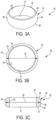
- retaining ring 36 is a generally ring-shaped component having a generally circular side wall 40 ( FIG. 3A ) defining a central opening 41.
- Side wall 40 includes a generally barrel-shaped outer surface 38 and a cylindrical inner surface 42 having a substantially constant cross-section.
- Outer surface 38 includes a curved upper portion 44 and a curved lower portion 46 connected by a central portion 48 with a less pronounced curvature.
- Side wall 40 further includes a substantially flat upper edge 45 and a substantially flat lower edge 47.
- Central opening 41 has a substantially constant diameter 53 between upper edge 45 and lower edge 47 of circular side wall 40.
- retaining ring 36 is formed from steel although other materials may be suitable in certain applications.
- retaining ring 36 may be inserted into sleeve 14 upper edge 45 first or lower edge 47 first.
- retaining ring 36 includes only one of curved upper portion 44 or curved lower portion 46.
- the edge 45, 47 corresponding to the curved portion provided must be installed first to permit the guiding and self-centering described herein.
- retaining ring 36 has an outer diameter 50 that is greater than an inner diameter 52 ( FIG. 2 ) of burnished area 34 of sleeve 14.
- outer diameter 50 is larger than inner diameter 52 by a distance in the range of 0.3 to 0.6 mm, and more preferably in the range of 0.35 to 0.5 mm.
- Tool 54 generally includes a handle 56, a threaded drive rod 58 and a guide end 60.
- Handle 56 includes a body 62 having a mounting bore 64 that extends between an upper side 66 of body 62 to a lower side 68 of body 62 and a drive end 70 having a boss 72.
- a threaded opening 74 extends through drive end 70 and receives drive rod 58.
- Drive rod 58 includes a threaded body 76 having a drive head 78 at one end and a rotatable coupling 79 ( FIG. 6 ) at the end connected to guide end 60.
- Guide end 60 has an upper engagement boss 80, a cylindrical body 82 sized to receive retaining ring 36, and a tip 84 configured to bottom out in injector bore 16. As is further described below, when guide end 60 is fully inserted into injector sleeve 14, tip 84 limits the insertion distance and engagement boss 80 locates retaining ring 36 at the proper installed location. Although FIG. 6 shows tip 84 limiting travel when contacting the cylinder head and controlling the insertion depth of retaining ring 36, this feature is not necessary and may be replaced, in other embodiments, by a guide end 60 possessing a diameter slightly undersized from the injector bore and slightly oversized from the injector sleeve diameter to limit travel upon contacting the upper edge face of sleeve 14.
- Mounting bore 64 is positioned on handle body 62 to align with a threaded opening 90 adjacent injector bore 16 normally used to receive a bolt for attaching the injector hold down clamp (not shown).
- a bolt 92 is passed through mounting bore 64 and threaded into opening 90 until handle 56 is tightly attached to cylinder head 18.
- a tool such as a wrench is used to rotate drive head 78 of drive rod 58, thereby forcing guide end 60 downwardly into sleeve 14.
- engagement boss 80 of guide end 60 forces retaining ring 36 into sleeve 14.
- retaining ring 36 As retaining ring 36 engages the upper edge of sleeve 14, one of curved portions 44, 46 (depending on the orientation of ring 36) of outer surface 38 guides and centers retaining ring 36 into sleeve 14.
- Drive head 78 is further rotated until tip 84 of guide end 60 bottoms out in injector bore 16.
- retaining ring 36 is positioned at the proper depth in its installed position within sleeve 14, and its larger outer diameter relative to the inner diameter of sleeve 14 applies outwardly directed force that re-stablishes a seal between sleeve 14 and bore 16 where the failed seal ring 30 is located.
- retaining ring 36 could be removed from sleeve 14 using a suitable tool that engages the lower edge (45 or 47) of retaining ring 36 and applies upward force to pull retaining ring 36 out of sleeve 14.
- tool 154 for installing a retaining ring 36 into injector sleeve 14.
- tool 154 generally includes a handle 156, a threaded drive rod 158 and a guide end 160.
- Handle 156 includes a body 162 having a mounting bore 164 that extends between an upper side 166 of body 162 to a lower side 168 of body 162 and a drive end 170 having a boss 172.
- a cap screw 171 extends through mounting bore 164 to attach tool 154 to cylinder head 18.
- a threaded opening 174 extends through drive end 170 and receives drive rod 158.
- Drive rod 158 includes a threaded body 176 having a drive head 178 at one end and a rotatable coupling 179 ( FIG. 9 ) at the end connected to guide end 160.
- Guide end 160 has an upper engagement boss 180, and a cylindrical body 182 sized to receive retaining ring 36.
- Drive rod 158 further includes a stop nut 184 that, in one embodiment, is attached in a fixed position on threaded body 176 adjacent drive head 178. As explained herein, as drive rod 158 is rotated using drive head 178, drive rod threads through drive end 170 of handle 156 and urges retaining ring 36 into injector bore 16.
- Stop nut 184 may be positioned on drive rod 158 to engage upper surface 166 of handle 156 to set the depth of insertion of retaining ring 36. In this manner, stop nut 184 provides for a repeatable insertion depth of retaining ring 36 and prevents over-tightening or under-tightening. In another embodiment, stop nut 184 may be adjustably positioned on drive rod 158 to provide for various different insertion depths.
- Handle body 162 further includes a pair of forward recesses 186, 188 configured to provide clearance for valve springs as depicted in FIG. 8 when tool 154 is attached to cylinder head 18.
- Body 162 also has a pair of rearward recesses 190, 192 configured to provide clearance for cylinder head cap screws as shown in FIG. 8 .
- handle body 162 includes an extension 194 having a threaded opening 196.
- a threaded bolt 198 extends through opening 196 and is pivotally connected to a foot 200. As is further described herein, bolt 198 is used to tighten foot 200 into engagement with cylinder head 18 to counter-balance the force applied when drive rod 158 is threaded into injector bore 16.
- retaining ring 36 is inserted into sleeve 14 to repair the seal provided by seal ring 30 using tool 154 in the following manner.
- injector clamp (not shown) is removed, fuel injector 12 is removed from sleeve 14.
- a retaining ring 36 is placed onto body 182 of guide end 160 of tool 154.
- Guide end 160 (with retaining ring 36) is then inserted into injector bore 16 and positioned down into sleeve 14.
- Boss 172 of drive end 170 of handle 156 is positioned into injector bore 16 as shown in FIG. 9 to properly orient drive rod 158.
- Mounting bore 164 is positioned on handle body 162 to align with a threaded opening 202 adjacent injector bore 16 normally used to receive a bolt for attaching the injector hold down clamp (not shown).
- Cap screw 171 is passed through mounting bore 164 and threaded into opening 202 until handle 156 is tightly attached to cylinder head 18.
- Bolt 198 is then tightened to force foot 200 into engagement with cylinder head 18.
- a tool such as a wrench is used to rotate drive head 178 of drive rod 158, thereby forcing guide end 160 downwardly into sleeve 14.
- engagement boss 180 of guide end 160 forces retaining ring 36 into sleeve 14.
- one of curved portions 44, 46 (depending on the orientation of ring 36) of outer surface 38 guides and centers retaining ring 36 into sleeve 14.
- Drive head 178 is further rotated until stop nut 184 engages upper surface 166 of drive end 170.
- retaining ring 36 is positioned at the proper depth in its installed position within sleeve 14, and its larger outer diameter relative to the inner diameter of sleeve 14 applies outwardly directed force that re-stablishes a seal between sleeve 14 and bore 16 where the failed seal ring 30 is located. It should be understood that retaining ring 36 could be removed from sleeve 14 using a suitable tool that engages the lower edge (45 or 47) of retaining ring 36 and applies upward force to pull retaining ring 36 out of sleeve 14.
- reaction forces are directed upwardly, urging tool 154 approximately in direction A of FIG. 9 .
- This force may damage cap screw 171 or other components of tool 154.
- foot 200 of extension 194 engages cylinder head 18, a similar reaction force is generated, urging tool 154 approximately in direction B of FIG. 9 .
- This reaction force serves to counter balance the force in direction A, and inhibits damage to tool 154. In this manner, the life of tool 154 is extended such that it may be used repeatedly to install multiple retaining rings 36.
Landscapes
- Engineering & Computer Science (AREA)
- Mechanical Engineering (AREA)
- Chemical & Material Sciences (AREA)
- Combustion & Propulsion (AREA)
- General Engineering & Computer Science (AREA)
- Fuel-Injection Apparatus (AREA)
Description
- The present application is related to and claims priority to
U.S. Provisional Application No. 62/414,996, filed on October 31, 2016 - The present invention relates generally to fuel injector sleeve seals and more particularly to structure and methods for in-field repair of a fuel injector sleeve leak at an upper seal location.
- Internal combustion engines having fuel injectors typically locate the injectors in bores formed in the cylinder head. An injector sleeve is normally inserted in the injector bore, and the injector is received within the sleeve. One or more coolant chambers are formed in the cylinder head and separated from the injector by the injector sleeve. To prevent leakage of coolant and/or combustion gas, a seal is typically formed between the sleeve and the cylinder bore above and below the coolant chamber. In some cases, one or both of the seals are formed of an elastomeric material.
- It is not unusual for the upper elastomeric seal to degrade over time and require replacement. Without an authorized procedure, kit or tool available to perform replacement/repair of the seal outside the reconditioning facility or original factory, the entire cylinder head generally requires removal. This technique is expensive, labor intensive and requires significant engine downtime. In fact, the cost of a new or reconditioned cylinder head may be more than $4,000, and labor (e.g., approximately 20 hours) may add an additional $2,000 to the overall expense. Alternatively, expensive after-market kits are available to repair a leaking injector sleeve by means of threading in a tap and pulling the sleeve out of the cylinder head, then pressing in a new sleeve. A sealing compound is typically required and used in dry, pre-applied form or by using additional sealant at the sleeve-to-cylinder head interface. This approach is also expensive, time consuming and complicated, and requires the removal of the entire injector sleeve. Accordingly, it is desirable to provide an inexpensive, quick and simple approach to be used in the field for repairing a leaking upper seal between an injector sleeve and the injector bore. US Pub.No. 2011067653 describes an injector seal assembly and method of sealing a coolant passage from an injector. The seal assembly includes a sealing sleeve sized and dimensioned to slip fit into an injector mounting bore and a retaining ring sized and dimensioned to be axially inserted into the sleeve. The ring contacts the sleeve and applies a radial force sufficient to create an interference fit and to move or yield an interface portion of the sleeve radially outward into sealing abutment against a wall forming the injector mounting bore to create a secure and reliable annular fluid seal.
- The invention is disclosed in the appended claims. According to the claimed invention, the present disclosure provides a method of repairing a seal between a fuel injector sleeve and fuel injector bore, comprising: removing a fuel injector from the fuel injector sleeve; the fuel injector sleeve having an upper portion comprising an annular groove for receiving a seal ring; installing a retaining ring in the fuel injector bore, the retaining ring having a side wall with an outer surface having a curved portion adjacent at least one edge to guide the retaining ring into the fuel injector bore, the retaining ring further having an outer diameter that is larger than an inner diameter of the fuel injector sleeve at a location adjacent the seal such that when the retaining ring is in an installed position, the fuel injector sleeve is deformed outwardly toward the fuel injector bore, thereby repairing the seal; and replacing the fuel injector. In one aspect of this embodiment, installing the retaining ring comprises placing the retaining ring on an insertion tool, inserting the insertion tool into the fuel injector sleeve, and using the insertion tool to force the retaining ring into its installed position. In a variant of this aspect, using the insertion tool to force the retaining ring into its installed position comprises rotating a drive rod of the insertion tool to cause an engagement boss of the insertion tool to force the retaining ring into the fuel injector sleeve until a stop nut mounted to the drive rod engages an upper surface of the insertion tool. In another variant, installing the retaining ring comprises attaching the insertion tool to a cylinder head forming the fuel injector bore. In a further modification of this variant, attaching the insertion tool to the cylinder head comprises positioning a mounting bore of a handle body of the insertion tool in alignment with an opening in the cylinder head adjacent the fuel injector bore and threading a cap screw through the mounting bore into the opening. In another modification, attaching the insertion tool to the cylinder head comprises threading a bolt through an opening in an extension of a handle body of the insertion tool, thereby causing a foot connected to the bolt to engage a surface of the cylinder head. In another aspect of this embodiment, the retaining ring comprises an outer surface including at least one of an upper curved portion and a lower curved portion, and a central portion having a curvature that is less pronounced than upper curved portion and lower curved portion such that the outer surface resembles a barrel. In a variant of this aspect, installing the retaining ring comprises centering the retaining ring in the fuel injector sleeve by the at least one of an upper curved portion and a lower curved portion of the retaining ring. In another variant, the upper curved portion of the retaining ring is adjacent a substantially flat upper edge of the retaining ring and the lower curved portion of the retaining ring is adjacent a substantially flat lower edge of the retaining ring. In another aspect, the outer diameter of the retaining ring is larger than the inner diameter of the fuel injector sleeve by a distance in the range of 0.3 to 0.6 mm. In a variant of this aspect, the outer diameter of the retaining ring is larger than the inner diameter of the fuel injector sleeve by a distance in the range of 0.35to 0.5 mm.
- In another embodiment according to the claimed invention, the present disclosure provides a retaining ring and a fuel injector sleeve, the retaining ring configured for in-field repair of a fuel injector sleeve upper seal leak, comprising: the fuel injector sleeve having an upper portion comprising an annular groove for receiving a seal ring, the retaining ring comprising a circular side wall comprising a barrel-shaped outer surface and a substantially cylindrical inner surface; wherein the outer surface comprises a lower curved portion and a central portion having a curvature that is less pronounced than the lower curved portion; and wherein the lower curved portion is configured to guide the retaining ring into the fuel injector sleeve and the circular side wall has an outer diameter at the central portion that is larger than an inner diameter of the fuel injector sleeve at a location of the upper seal leak such that the retaining ring forces the fuel injector sleeve outwardly at the location of the upper seal leak as the retaining ring is moved into an installed position. In one aspect of this embodiment, the circular side wall comprises an upper edge between the inner surface and the outer surface, and a lower edge between the inner surface and the outer surface. In a variant of this aspect, the lower curved portion is adjacent the lower edge of the circular side wall. In another aspect, the circular side wall defines a central opening having a substantially constant diameter between the upper edge and the lower edge of the circular side wall. In still another aspect, the outer surface further comprises an upper curved portion adjacent the upper edge. In yet another aspect, the outer diameter at the central portion of the retaining ring is larger than the inner diameter of the fuel injector sleeve by a distance in the range of 0.3 to 0.6 mm. In a variant of this aspect, the outer diameter at the central portion of the retaining ring is larger than the inner diameter of the fuel injector sleeve by a distance in the range of 0.35 to 0.5 mm.
- In yet another embodiment, the present disclosure provides a system for in-field repair of a fuel injector sleeve upper seal leak, comprising: a retaining ring comprising a circular side wall having an outer surface and defining a central opening, the outer surface comprising a lower portion configured to guide the retaining ring into the fuel injector sleeve and a central portion having a diameter that is larger than an inner diameter of the fuel injector sleeve adjacent the upper seal leak; and an insertion tool comprising a handle, a threaded drive rod coupled to the handle and a guide end coupled to the threaded drive rod and configured to extend into the fuel injector sleeve, the handle including a mounting bore configured to receive a cap screw for mounting the insertion tool to a cylinder head of an engine, the threaded drive rod including a drive head, and the guide end being configured to extend through the central opening of the retaining ring and having an engagement boss that forces the retaining ring into an installed position in the fuel injector sleeve in response to rotation of the drive head when the handle is mounted to the cylinder head; wherein the outer surface of the retaining ring forces the fuel injector sleeve outwardly at the location of the upper seal leak as the retaining ring is forced into its installed position. In one aspect of this embodiment, the central portion of the outer surface has a curvature that is less pronounced than a curvature of the lower portion. In a variant of this aspect, the retaining ring further comprises an upper portion having a curvature that is more pronounced than the curvature of the central portion such that the outer surface resembles a barrel. In still another aspect of this embodiment, the insertion tool handle includes an extension opposite the mounting bore, the extension including an opening for receiving a bolt coupled to a foot configured to engage the cylinder head.
- While multiple embodiments are disclosed, still other embodiments of the present invention will become apparent to those skilled in the art from the following detailed description, which shows and describes illustrative embodiments of the invention. Accordingly, the drawings and detailed description are to be regarded as illustrative in nature and not restrictive.
- The above-mentioned and other features of this disclosure and the manner of obtaining them will become more apparent and the disclosure itself will be better understood by reference to the following description of embodiments of the present disclosure taken in conjunction with the accompanying drawings, wherein:
-
FIG. 1 is a cross-sectional view of a fuel injector assembly; -
FIG. 2 is a cross-sectional view of a fuel injector assembly having a retaining ring according to one embodiment of the present disclosure installed to repair an upper seal leak of a fuel injector; -
FIG. 3A is a perspective view of the retaining ring ofFIG. 2 ; -
FIG. 3B is a top plan view of the retaining ring ofFIG. 2 ; -
FIG. 3C is a cross-sectional view of the retaining ring ofFIG. 2 ; -
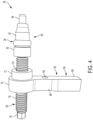
FIG. 4 is a perspective view of an insertion tool for inserting the retaining ring ofFIG. 2 ; -
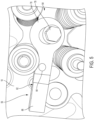
FIG. 5 is a top plan view of the insertion tool ofFIG. 4 ; -
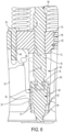
FIG. 6 is a cross-sectional side view of the insertion tool ofFIG. 4 being used to install the retaining ring ofFIG. 2 ; -
FIG. 7 is a perspective view of another embodiment of an insertion tool for inserting the retaining ring ofFIG. 2 ; -
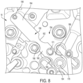
FIG. 8 is a top plan view of the insertion tool ofFIG. 7 ; and -
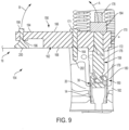
FIG. 9 is a cross-sectional side view of the insertion tool ofFIG. 7 being used to install the retaining ring ofFIG. 2 . - While the present disclosure is amenable to various modifications and alternative forms, specific embodiments have been shown by way of example in the drawings and are described in detail below. The present disclosure, however, is not to limit the particular embodiments described. On the contrary, the present disclosure is intended to cover all modifications, equivalents, and alternatives falling within the scope of the appended claims.
- As used herein, the modifier "about" used in connection with a quantity is inclusive of the stated value and has the meaning dictated by the context (for example, it includes at least the degree of error associated with the measurement of the particular quantity). When used in the context of a range, the modifier "about" should also be considered as disclosing the range defined by the absolute values of the two endpoints. For example, the range "from about 2 to about 4" also discloses the range "from 2 to 4."
- The present disclosure provides a field repair procedure and system that permits repair of a leaking elastomeric (or other material) upper injector seal without the need to remove the cylinder head or injector sleeve. As is further described below, a retaining ring having a barrel shaped outer contour which is substantially self-centering and self-guiding is installed into the injector sleeve in-situ and sized with an outer diameter which is larger than the inner diameter of the injector sleeve to cause an interference fit that re-establishes sealing capability after a leak has developed. Installation of the retainer ring may be accomplished using a simple pressing or impact tool which extends into the cylinder bore to seat to the proper depth. Using the procedure and system described herein, a seal may be repaired for a small fraction of the cost with greatly reduced engine downtime.
- Referring now to
FIG. 1 , a typicalfuel injector assembly 10 is shown.Assembly 10 generally includes afuel injector 12 disposed within aninjector sleeve 14, which in turn is disposed within an injector bore 16 formed in acylinder head 18.Cylinder head 18 includes acoolant passage 20 in fluid communication with injector bore 16. A retainingring 22 may be positioned in the lower portion ofsleeve 14 to provide a lower seal ofcoolant passage 20 at aninterface portion 24 having abore sealing surface 26 as described inU.S. Patent No. 8,230,808 , entitled INJECTOR SEAL ASSEMBLY AND METHOD OF SEALING A COOLANT PASSAGE FROM AN INJECTOR, which is also owned by the present assignee.Sleeve 14 generally has aside wall 29 with a cylindrical or tubular shape formed of appropriate material to be slip fit into place inbore 16. At an upper end,sleeve 14 typically includes anannular groove 28 for receiving aseal ring 30 which may be made of an elastomeric material. In other embodiments,seal ring 30 andannular groove 28 may be omitted, or replaced with a series of shallow grooves to enhance plasticity of the sleeve outer surface. In either case, thesleeve 14 is sized with an appropriate diameter to create a close fit, and is then typically rolled with a conventional rolling device to form a seal withbore 16 and create a slight locking feature of sleeve material into the coolant passage. In this manner,coolant passage 20 is separated from theannular chamber 32 betweeninjector 12 andsleeve 14, which usually is filled with low pressure fuel. As shown, in certain embodiments the upper end ofsleeve 14 has a burnishedarea 34. - Under certain conditions and/or over time,
seal ring 30 may degrade and leak. As indicated above, replacement/repair ofseal ring 30 using conventional techniques may be expensive, time consuming and complicated. The present disclosure provides a technique and system for repairing the seal provided byseal ring 30 in the field without removingsleeve 14 and without replacingcylinder head 18. According to one embodiment of the present disclosure, a retainingring 36 is provided to repair the seal provided byseal ring 30. As shown generally inFIG. 2 , retainingring 36 is positioned betweenfuel injector 12 andinjector sleeve 14 to press outwardly againstsleeve 14 to repair the seal earlier provided by the damaged/degraded seal ring 30. - Referring now to
FIG. 3A-3C , retainingring 36 is a generally ring-shaped component having a generally circular side wall 40 (FIG. 3A ) defining acentral opening 41.Side wall 40 includes a generally barrel-shapedouter surface 38 and a cylindricalinner surface 42 having a substantially constant cross-section.Outer surface 38 includes a curvedupper portion 44 and a curvedlower portion 46 connected by acentral portion 48 with a less pronounced curvature.Side wall 40 further includes a substantially flatupper edge 45 and a substantially flatlower edge 47.Central opening 41 has a substantiallyconstant diameter 53 betweenupper edge 45 andlower edge 47 ofcircular side wall 40. In some embodiments, retainingring 36 is formed from steel although other materials may be suitable in certain applications. As should be apparent from the description herein, retainingring 36 may be inserted intosleeve 14upper edge 45 first orlower edge 47 first. In other embodiments, retainingring 36 includes only one of curvedupper portion 44 or curvedlower portion 46. In such an embodiment, theedge - As a
typical injector sleeve 14 has little or no leading chamfer along its upper edge, during insertionlower portion 46 ofouter surface 38permits retaining ring 36 to be centered and guided into an installed state as is further described below. At least atcentral portion 48, retainingring 36 has anouter diameter 50 that is greater than an inner diameter 52 (FIG. 2 ) of burnishedarea 34 ofsleeve 14. Because of this, insertion of retainingring 36 into burnishedarea 34 of sleeve 14 (with a tool such as that described below) expandssleeve 14 atburnished area 34 to cause sleeve 14 (with or without an elastomeric seal ring 30) to provide additional sealing pressure betweensleeve 14 and bore 16 to prevent leakage and repair the earlier provided seal. In one embodiment,outer diameter 50 is larger thaninner diameter 52 by a distance in the range of 0.3 to 0.6 mm, and more preferably in the range of 0.35 to 0.5 mm. - Referring now to
FIG. 4 , oneexample insertion tool 54 is depicted with a retainingring 36 mounted for insertion intoinjector sleeve 14.Tool 54 generally includes ahandle 56, a threadeddrive rod 58 and aguide end 60.Handle 56 includes abody 62 having a mountingbore 64 that extends between anupper side 66 ofbody 62 to alower side 68 ofbody 62 and adrive end 70 having aboss 72. A threaded opening 74 extends throughdrive end 70 and receives driverod 58. Driverod 58 includes a threadedbody 76 having adrive head 78 at one end and a rotatable coupling 79 (FIG. 6 ) at the end connected to guideend 60.Guide end 60 has anupper engagement boss 80, acylindrical body 82 sized to receive retainingring 36, and atip 84 configured to bottom out in injector bore 16. As is further described below, whenguide end 60 is fully inserted intoinjector sleeve 14,tip 84 limits the insertion distance andengagement boss 80 locates retainingring 36 at the proper installed location. AlthoughFIG. 6 showstip 84 limiting travel when contacting the cylinder head and controlling the insertion depth of retainingring 36, this feature is not necessary and may be replaced, in other embodiments, by aguide end 60 possessing a diameter slightly undersized from the injector bore and slightly oversized from the injector sleeve diameter to limit travel upon contacting the upper edge face ofsleeve 14. - Referring now to
FIGs. 5 and6 , retainingring 36 is inserted intosleeve 14 to repair the seal provided byseal ring 30 usingtool 54 in the following manner. After the injector clamp (not shown) is removed,fuel injector 12 is removed fromsleeve 14. A retainingring 36 is placed ontobody 82 ofguide end 60 oftool 54. Guide end 60 (with retaining ring 36) is then inserted into injector bore 16 and positioned down intosleeve 14.Boss 72 ofdrive end 70 ofhandle 56 is positioned into injector bore 16 as shown inFIG. 6 to properly orientdrive rod 58. Mounting bore 64 is positioned onhandle body 62 to align with a threadedopening 90 adjacent injector bore 16 normally used to receive a bolt for attaching the injector hold down clamp (not shown). Abolt 92 is passed through mountingbore 64 and threaded intoopening 90 untilhandle 56 is tightly attached tocylinder head 18. After handle 56 (and therefore tool 54) is secured tocylinder head 18, a tool such as a wrench is used to rotatedrive head 78 ofdrive rod 58, thereby forcing guide end 60 downwardly intosleeve 14. Asguide end 60 moves downwardly,engagement boss 80 ofguide end 60forces retaining ring 36 intosleeve 14. As retainingring 36 engages the upper edge ofsleeve 14, one ofcurved portions 44, 46 (depending on the orientation of ring 36) ofouter surface 38 guides andcenters retaining ring 36 intosleeve 14. Drivehead 78 is further rotated untiltip 84 ofguide end 60 bottoms out in injector bore 16. When this occurs, retainingring 36 is positioned at the proper depth in its installed position withinsleeve 14, and its larger outer diameter relative to the inner diameter ofsleeve 14 applies outwardly directed force that re-stablishes a seal betweensleeve 14 and bore 16 where the failedseal ring 30 is located. It should be understood that retainingring 36 could be removed fromsleeve 14 using a suitable tool that engages the lower edge (45 or 47) of retainingring 36 and applies upward force to pull retainingring 36 out ofsleeve 14. - Referring now to
FIG. 7 , anotherexample insertion tool 154 is depicted for installing a retainingring 36 intoinjector sleeve 14. Liketool 54 ofFIG. 4 ,tool 154 generally includes ahandle 156, a threadeddrive rod 158 and aguide end 160. Handle 156 includes abody 162 having a mountingbore 164 that extends between anupper side 166 ofbody 162 to alower side 168 ofbody 162 and adrive end 170 having aboss 172. As described below, acap screw 171 extends through mountingbore 164 to attachtool 154 tocylinder head 18. A threadedopening 174 extends throughdrive end 170 and receivesdrive rod 158. Driverod 158 includes a threadedbody 176 having adrive head 178 at one end and a rotatable coupling 179 (FIG. 9 ) at the end connected to guideend 160.Guide end 160 has anupper engagement boss 180, and acylindrical body 182 sized to receive retainingring 36. Driverod 158 further includes astop nut 184 that, in one embodiment, is attached in a fixed position on threadedbody 176adjacent drive head 178. As explained herein, asdrive rod 158 is rotated usingdrive head 178, drive rod threads throughdrive end 170 ofhandle 156 and urges retainingring 36 into injector bore 16. Stopnut 184 may be positioned ondrive rod 158 to engageupper surface 166 ofhandle 156 to set the depth of insertion of retainingring 36. In this manner, stopnut 184 provides for a repeatable insertion depth of retainingring 36 and prevents over-tightening or under-tightening. In another embodiment, stopnut 184 may be adjustably positioned ondrive rod 158 to provide for various different insertion depths. - Handle
body 162 further includes a pair offorward recesses FIG. 8 whentool 154 is attached tocylinder head 18.Body 162 also has a pair ofrearward recesses FIG. 8 . Finally, handlebody 162 includes anextension 194 having a threadedopening 196. A threadedbolt 198 extends throughopening 196 and is pivotally connected to afoot 200. As is further described herein,bolt 198 is used to tightenfoot 200 into engagement withcylinder head 18 to counter-balance the force applied whendrive rod 158 is threaded into injector bore 16. - Referring now to
FIGs. 8 and9 , retainingring 36 is inserted intosleeve 14 to repair the seal provided byseal ring 30 usingtool 154 in the following manner. After the injector clamp (not shown) is removed,fuel injector 12 is removed fromsleeve 14. A retainingring 36 is placed ontobody 182 ofguide end 160 oftool 154. Guide end 160 (with retaining ring 36) is then inserted into injector bore 16 and positioned down intosleeve 14.Boss 172 ofdrive end 170 ofhandle 156 is positioned into injector bore 16 as shown inFIG. 9 to properly orientdrive rod 158. Mountingbore 164 is positioned onhandle body 162 to align with a threadedopening 202 adjacent injector bore 16 normally used to receive a bolt for attaching the injector hold down clamp (not shown).Cap screw 171 is passed through mountingbore 164 and threaded intoopening 202 untilhandle 156 is tightly attached tocylinder head 18.Bolt 198 is then tightened to forcefoot 200 into engagement withcylinder head 18. - After handle 156 (and therefore tool 154) is secured to
cylinder head 18 in the manner described above, a tool such as a wrench is used to rotatedrive head 178 ofdrive rod 158, thereby forcing guide end 160 downwardly intosleeve 14. Asguide end 160 moves downwardly,engagement boss 180 ofguide end 160forces retaining ring 36 intosleeve 14. As retainingring 36 engages the upper edge ofsleeve 14, one ofcurved portions 44, 46 (depending on the orientation of ring 36) ofouter surface 38 guides andcenters retaining ring 36 intosleeve 14.Drive head 178 is further rotated untilstop nut 184 engagesupper surface 166 ofdrive end 170. When this occurs, retainingring 36 is positioned at the proper depth in its installed position withinsleeve 14, and its larger outer diameter relative to the inner diameter ofsleeve 14 applies outwardly directed force that re-stablishes a seal betweensleeve 14 and bore 16 where the failedseal ring 30 is located. It should be understood that retainingring 36 could be removed fromsleeve 14 using a suitable tool that engages the lower edge (45 or 47) of retainingring 36 and applies upward force to pull retainingring 36 out ofsleeve 14. - As
drive rod 158forces retaining ring 36 downwardly into position withinsleeve 14, reaction forces are directed upwardly, urgingtool 154 approximately in direction A ofFIG. 9 . This force may damagecap screw 171 or other components oftool 154. In this embodiment, whenfoot 200 ofextension 194 engagescylinder head 18, a similar reaction force is generated, urgingtool 154 approximately in direction B ofFIG. 9 . This reaction force serves to counter balance the force in direction A, and inhibits damage totool 154. In this manner, the life oftool 154 is extended such that it may be used repeatedly to install multiple retaining rings 36. - It should also be understood that the principles described herein may also be used for initial manufacturing assembly of fuel injector sleeves in cylinder heads. This would eliminate the need for burnishing and the time associated with that operation. Moreover, in certain applications it would eliminate the need for an elastomeric upper injector seal.
- It should be further understood that, the connecting lines shown in the various figures contained herein are intended to represent exemplary functional relationships and/or physical couplings between the various elements. It should be noted that many alternative or additional functional relationships or physical connections may be present in a practical system. However, the benefits, advantages, solutions to problems, and any elements that may cause any benefit, advantage, or solution to occur or become more pronounced are not to be construed as critical, required, or essential features or elements. The scope is accordingly to be limited by nothing other than the appended claims, in which reference to an element in the singular is not intended to mean "one and only one" unless explicitly so stated, but rather "one or more." Moreover, where a phrase similar to "at least one of A, B, or C" is used in the claims, it is intended that the phrase be interpreted to mean that A alone may be present in an embodiment, B alone may be present in an embodiment, C alone may be present in an embodiment, or that any combination of the elements A, B or C may be present in a single embodiment; for example, A and B, A and C, B and C, or A and B and C.
Claims (15)
- A method of repairing a seal between a fuel injector sleeve (14) and a fuel injector bore (16), comprising:removing a fuel injector (12) from the fuel injector sleeve (14), the fuel injector sleeve (14) having an upper portion comprising an annular groove (28) for receiving a seal ring (30);installing a retaining ring (36) in the fuel injector bore (16), the retaining ring (36) having a side wall (40) with an outer surface (38) including a curved portion adjacent at least one edge of the side wall to guide the retaining ring (36) into the fuel injector bore (16), replacing the fuel injector (12) in the fuel injector sleeve (14), the method characterised inthe retaining ring (36) further having an outer diameter that is larger than an inner diameter of the upper portion of the fuel injector sleeve (14) at a location adjacent an upper seal leak in the upper portion of the fuel injector sleeve (14) such that when the retaining ring (36) is in an installed position, the upper portion of the fuel injector sleeve (14) is deformed outwardly toward the fuel injector bore (16), to thereby repair the upper seal leak.
- The method of claim 1, wherein installing the retaining ring (36) comprises placing the retaining ring (36) on an insertion tool (54), inserting the insertion tool (54) into the fuel injector sleeve (14), and using the insertion tool (54) to force the retaining ring (36) into the installed position.
- The method of claim 2, wherein using the insertion tool (54) to force the retaining ring (36) into the installed position comprises rotating a drive rod of the insertion tool (54) to cause an engagement boss of the insertion tool (54) to force the retaining ring (36) into the fuel injector sleeve (14) until a stop nut mounted to the drive rod engages an upper surface of the insertion tool (54).
- The method of claim 2, wherein installing the retaining ring (36) further comprises attaching the insertion tool (54) to a cylinder head (18) forming the fuel injector bore (16), wherein attaching the insertion tool (54) to the cylinder head (18) comprises:positioning a mounting bore of a handle body of the insertion tool (54) in alignment with an opening in the cylinder head (18) adjacent the fuel injector bore (16);threading a cap screw through the mounting bore into the opening; and/or threading a bolt through an opening in an extension of a handle body of the insertion tool (54), thereby causing a foot connected to the bolt to engage a surface of the cylinder head (18).
- The method of claim 1, wherein the curved portion of the outer surface of the retaining ring (36) includes an outer surface at least one of an upper curved portion and a lower curved portion, and a central portion having a curvature that is less pronounced than the upper curved portion and the lower curved portion such that the outer surface resembles a barrel.
- The method of claim 5, wherein installing the retaining ring (36) comprises centering the retaining ring (36) in the fuel injector sleeve (14) by at least one of the upper curved portion and the lower curved portion.
- The method of claim 5, wherein the upper curved portion is adjacent a substantially flat upper edge of the retaining ring (36) and the lower curved portion is adjacent a substantially flat lower edge of the retaining ring (36).
- The method of claim 1, wherein the outer diameter of the retaining ring (36) is larger than the inner diameter of the upper portion of the fuel injector sleeve (14) by a distance in a range of 0.3 to 0.6 mm or in a range of 0.35 to 0.5 mm.
- A retaining ring (36) and a fuel injector sleeve (14), the retaining ring (36) configured for in-field repair of a fuel injector sleeve (14) upper seal leak, comprising:the fuel injector sleeve (14) having an upper portion comprising an annular groove (28) for receiving a seal ring (30);the retaining ring (36) comprising a circular side wall (40) having a barrel-shaped outer surface (38) and a substantially cylindrical inner surface (42); andwherein:the outer surface (38) comprises a lower curved portion (46) having a curvature and a central portion (48) having a curvature that is less pronounced than the curvature of the lower curved portion; andwherein the lower curved portion (46) is configured to guide the retaining ring (36) into the upper portion of the fuel injector sleeve (14); andthe retaining ring and the fuel injector sleeve characterised in that the circular side wall (40) has an outer diameter at the central portion (48) that is larger than an inner diameter of the upper portion of the fuel injector sleeve (14) at a location of an upper seal leak such that the retaining ring (36) forces the upper portion of the fuel injector sleeve (14) to deform outwardly at the location of the upper seal leak as the retaining ring (36) is moved into an installed position.
- The retaining ring and fuel injector sleeve of claim 9, wherein:
the circular side wall (40) comprises an upper edge between the inner surface and the outer surface (38), and a lower edge between the inner surface and the outer surface (38);
the lower curved portion (46) is adjacent the lower edge of the circular side wall (40); or the circular side wall (40) defines a central opening having a substantially constant diameter between the upper edge and the lower edge. - The retaining ring and fuel injector sleeve of claim 9, wherein the outer surface (38) further comprises an upper curved portion adjacent the upper edge of the circular side wall (40).
- The retaining ring and fuel injector sleeve of claim 9, wherein the outer diameter at the central portion is larger than the inner diameter of the upper portion of the fuel injector sleeve (14) by a distance in a range of 0.3 to 0.6 mm or in a range of 0.35 to 0.5 mm.
- A system for in-field repair of a fuel injector sleeve (14) upper seal leak, comprising:a retaining ring (36) and a fuel injector sleeve (14) as claimed in claim 9; andan insertion tool (54) comprising:a handle (56) including a mounting bore (64) configured to receive a cap screw (171) for mounting the insertion tool (54) to a cylinder head (18) of an engine;a threaded drive rod (58) including a drive head (78) and coupled to the handle; anda guide end (60) coupled to the threaded drive rod (58), the guide end being configured to extend into the fuel injector sleeve (14) and to extend through the central opening (41) of the retaining ring (36),characterised by the guide end having an engagement boss (80) that forces the retaining ring (36) into an installed position in the upper portion of the fuel injector sleeve (14) in response to a rotation of the drive head when the handle (56) is mounted to the cylinder head (18).
- The system of claim 13, wherein the outer surface further comprising an upper curved portion having a curvature that is more pronounced than the curvature of the central portion.
- The system of claim 13, wherein the handle (56) of the insertion tool (54) includes an extension having an opening for receiving a bolt coupled to a foot configured to engage the cylinder head (18).
Applications Claiming Priority (2)
| Application Number | Priority Date | Filing Date | Title |
|---|---|---|---|
| US201662414996P | 2016-10-31 | 2016-10-31 | |
| PCT/US2017/038258 WO2018080598A1 (en) | 2016-10-31 | 2017-06-20 | Injector sleeve assembly and method for field repair procedure |
Publications (3)
| Publication Number | Publication Date |
|---|---|
| EP3516202A1 EP3516202A1 (en) | 2019-07-31 |
| EP3516202A4 EP3516202A4 (en) | 2020-06-10 |
| EP3516202B1 true EP3516202B1 (en) | 2024-08-21 |
Family
ID=62025310
Family Applications (1)
| Application Number | Title | Priority Date | Filing Date |
|---|---|---|---|
| EP17863497.8A Active EP3516202B1 (en) | 2016-10-31 | 2017-06-20 | Injector sleeve assembly and method for field repair procedure |
Country Status (4)
| Country | Link |
|---|---|
| US (1) | US11192210B2 (en) |
| EP (1) | EP3516202B1 (en) |
| CN (2) | CN121803378A (en) |
| WO (1) | WO2018080598A1 (en) |
Families Citing this family (8)
| Publication number | Priority date | Publication date | Assignee | Title |
|---|---|---|---|---|
| DE102017218007A1 (en) * | 2017-10-10 | 2019-04-11 | Robert Bosch Gmbh | Decoupling element for a fuel injection device |
| DE102017218002A1 (en) * | 2017-10-10 | 2019-04-11 | Robert Bosch Gmbh | Decoupling element for a fuel injection device |
| DE102017221203A1 (en) * | 2017-11-27 | 2019-05-29 | Hyundai Motor Company | A fuel injection system and method of operating a fuel injection system |
| DE102020214481A1 (en) * | 2020-11-18 | 2022-05-19 | Robert Bosch Gesellschaft mit beschränkter Haftung | Fuel injector for the metered delivery of fuel |
| USD990520S1 (en) * | 2020-12-21 | 2023-06-27 | Shifukang Industrial Co., Ltd. | Base of fuel injector puller |
| DE102022209290A1 (en) * | 2022-09-07 | 2024-03-07 | Robert Bosch Gesellschaft mit beschränkter Haftung | Injection valve for fuels, cylinder head with injection valve, method for installing an injection valve in a cylinder head and use of a cylindrical receptacle of a cylinder head as the outer shell of an injection valve |
| US12352229B2 (en) * | 2022-12-22 | 2025-07-08 | Robert Bosch Gmbh | Fuel injector dust seal |
| US20250354532A1 (en) * | 2024-05-14 | 2025-11-20 | Caterpillar Inc. | Fuel injector sleeve and engine system remanufacturing method using same |
Citations (1)
| Publication number | Priority date | Publication date | Assignee | Title |
|---|---|---|---|---|
| US20040069279A1 (en) * | 2001-07-07 | 2004-04-15 | Sieghart Maier | High-pressure fuel device |
Family Cites Families (20)
| Publication number | Priority date | Publication date | Assignee | Title |
|---|---|---|---|---|
| US3605703A (en) * | 1970-05-22 | 1971-09-20 | Gen Motors Corp | Fuel injection |
| US4018462A (en) | 1975-10-31 | 1977-04-19 | Hitachi Metals, Ltd. | Pipe fitting |
| JPS5565085A (en) * | 1978-11-07 | 1980-05-16 | Akito Shigeoka | Drawing tool of fuel injection valve in diesel engine |
| US5345913A (en) | 1993-11-24 | 1994-09-13 | Caterpillar Inc. | Injector assembly |
| US6289876B1 (en) * | 1999-03-29 | 2001-09-18 | International Truck And Engine Corporation | Fuel injector |
| DE10108194A1 (en) | 2001-02-21 | 2002-08-29 | Bosch Gmbh Robert | Sealing device for a fuel injector |
| US6866026B2 (en) * | 2002-08-28 | 2005-03-15 | Federal-Mogul World Wide, Inc. | Gasket for fuel injector |
| US7551705B2 (en) * | 2003-12-11 | 2009-06-23 | Areva Np, Inc. | Fuel assembly top nozzle repair sleeve and method for repairing a fuel assembly |
| BRPI0807545A2 (en) * | 2007-05-02 | 2014-06-17 | Bosch Gmbh Robert | INTERNAL COMBUSTION ENGINE WITH SEAL PROTECTION FOR A FUEL INJECTION VALVE |
| US8061142B2 (en) * | 2008-04-11 | 2011-11-22 | General Electric Company | Mixer for a combustor |
| US8490263B2 (en) * | 2008-08-28 | 2013-07-23 | Whitaker Tools, Inc. | Injector sleeve removal tool |
| US9382887B2 (en) | 2009-09-23 | 2016-07-05 | Cummins Intellectual Property. Inc. | Engine component seal assembly and method of sealing a coolant passage from an engine component |
| US8230838B2 (en) | 2009-09-23 | 2012-07-31 | Cummins Intellectual Properties, Inc. | Injector seal assembly and method of sealing a coolant passage from an injector |
| US20120139190A1 (en) * | 2010-12-06 | 2012-06-07 | Microflex Technologies, Llc | Ring seal retainer assembly and methods |
| DE202010016349U1 (en) * | 2010-12-08 | 2011-03-17 | Sauer Spezialwerkzeug Gmbh | Tool for releasing stuck connections |
| US9370845B2 (en) | 2013-07-19 | 2016-06-21 | Cummins Inc. | Method of repairing a cracked head using an injector bore insert |
| US9410520B2 (en) * | 2013-08-08 | 2016-08-09 | Cummins Inc. | Internal combustion engine including an injector combustion seal positioned between a fuel injector and an engine body |
| US9364924B2 (en) | 2013-10-11 | 2016-06-14 | Kennieth Neal | Method and apparatus for repairing a cylinder head |
| CN103753487B (en) * | 2014-01-17 | 2016-04-20 | 德清方山五金工具有限公司 | Diesel engine injector water spacer extractor |
| US10471554B2 (en) * | 2017-08-22 | 2019-11-12 | Caterpillar Inc. | Fuel injector bore repair |
-
2017
- 2017-06-20 EP EP17863497.8A patent/EP3516202B1/en active Active
- 2017-06-20 CN CN202610237628.6A patent/CN121803378A/en active Pending
- 2017-06-20 US US16/346,272 patent/US11192210B2/en active Active
- 2017-06-20 CN CN201780065911.4A patent/CN110268154B/en active Active
- 2017-06-20 WO PCT/US2017/038258 patent/WO2018080598A1/en not_active Ceased
Patent Citations (1)
| Publication number | Priority date | Publication date | Assignee | Title |
|---|---|---|---|---|
| US20040069279A1 (en) * | 2001-07-07 | 2004-04-15 | Sieghart Maier | High-pressure fuel device |
Also Published As
| Publication number | Publication date |
|---|---|
| WO2018080598A1 (en) | 2018-05-03 |
| EP3516202A1 (en) | 2019-07-31 |
| CN110268154B (en) | 2026-03-17 |
| US20190255664A1 (en) | 2019-08-22 |
| EP3516202A4 (en) | 2020-06-10 |
| CN110268154A (en) | 2019-09-20 |
| CN121803378A (en) | 2026-04-07 |
| US11192210B2 (en) | 2021-12-07 |
Similar Documents
| Publication | Publication Date | Title |
|---|---|---|
| EP3516202B1 (en) | Injector sleeve assembly and method for field repair procedure | |
| US20200080661A1 (en) | Hydraulic fluid pump and retainer assembly for same | |
| US7617712B2 (en) | Alignment device and methods of using the same | |
| US4324407A (en) | Pressure actuated metal-to-metal seal | |
| US20240401552A1 (en) | Injector cup for engines apparatus and methods of use | |
| US6969071B2 (en) | Face seal assembly | |
| CN112192499A (en) | Installation tool and installation method for high-pressure oil pump plunger combined type O-shaped sealing ring | |
| US4913464A (en) | Tubular joint with seal | |
| US9382871B2 (en) | Method for repair of cylinder block including water ferrule | |
| US7845619B2 (en) | Two-part back cap for a plug valve and plug valves incorporating same | |
| US20170276269A1 (en) | Pipe connector | |
| CA2324175A1 (en) | Swivel coupling and meyhod for attaching a swivel nut to a tail piece | |
| US20230066412A1 (en) | Installation tool | |
| US11905947B2 (en) | Fluid end of a hydraulic fluid pump and method of assembling the same | |
| US12215801B2 (en) | Valve packing apparatus and related methods | |
| US20230151702A1 (en) | Weldless drilling diverter adapter | |
| US20110044783A1 (en) | Retainer Apparatus | |
| CA2546160C (en) | Two-part back cap for a plug valve and plug valves incorporating same | |
| CN120312907A (en) | A step-by-step submarine pipeline connector | |
| CN117730211A (en) | Installation and disassembly components, shaft and bearing components, installation methods and disassembly methods | |
| US20150137021A1 (en) | Replacement Valve Guide with Elastomeric Seal |
Legal Events
| Date | Code | Title | Description |
|---|---|---|---|
| STAA | Information on the status of an ep patent application or granted ep patent |
Free format text: STATUS: THE INTERNATIONAL PUBLICATION HAS BEEN MADE |
|
| PUAI | Public reference made under article 153(3) epc to a published international application that has entered the european phase |
Free format text: ORIGINAL CODE: 0009012 |
|
| STAA | Information on the status of an ep patent application or granted ep patent |
Free format text: STATUS: REQUEST FOR EXAMINATION WAS MADE |
|
| 17P | Request for examination filed |
Effective date: 20190425 |
|
| AK | Designated contracting states |
Kind code of ref document: A1 Designated state(s): AL AT BE BG CH CY CZ DE DK EE ES FI FR GB GR HR HU IE IS IT LI LT LU LV MC MK MT NL NO PL PT RO RS SE SI SK SM TR |
|
| REG | Reference to a national code |
Ipc: B25B0027000000 Ref country code: DE Ref legal event code: R079 Ref document number: 602017084318 Country of ref document: DE Free format text: PREVIOUS MAIN CLASS: F02M0061160000 |
|
| A4 | Supplementary search report drawn up and despatched |
Effective date: 20200511 |
|
| RIC1 | Information provided on ipc code assigned before grant |
Ipc: B25B 23/00 20060101ALI20200504BHEP Ipc: F02M 61/14 20060101ALI20200504BHEP Ipc: F02M 53/04 20060101ALI20200504BHEP Ipc: F02M 53/00 20060101ALI20200504BHEP Ipc: B23P 6/00 20060101ALI20200504BHEP Ipc: F02F 11/00 20060101ALI20200504BHEP Ipc: B25B 27/00 20060101AFI20200504BHEP Ipc: B23P 6/04 20060101ALI20200504BHEP |
|
| STAA | Information on the status of an ep patent application or granted ep patent |
Free format text: STATUS: EXAMINATION IS IN PROGRESS |
|
| 17Q | First examination report despatched |
Effective date: 20220304 |
|
| GRAP | Despatch of communication of intention to grant a patent |
Free format text: ORIGINAL CODE: EPIDOSNIGR1 |
|
| STAA | Information on the status of an ep patent application or granted ep patent |
Free format text: STATUS: GRANT OF PATENT IS INTENDED |
|
| INTG | Intention to grant announced |
Effective date: 20230418 |
|
| P01 | Opt-out of the competence of the unified patent court (upc) registered |
Effective date: 20230510 |
|
| GRAJ | Information related to disapproval of communication of intention to grant by the applicant or resumption of examination proceedings by the epo deleted |
Free format text: ORIGINAL CODE: EPIDOSDIGR1 |
|
| STAA | Information on the status of an ep patent application or granted ep patent |
Free format text: STATUS: EXAMINATION IS IN PROGRESS |
|
| INTC | Intention to grant announced (deleted) | ||
| GRAP | Despatch of communication of intention to grant a patent |
Free format text: ORIGINAL CODE: EPIDOSNIGR1 |
|
| STAA | Information on the status of an ep patent application or granted ep patent |
Free format text: STATUS: GRANT OF PATENT IS INTENDED |
|
| INTG | Intention to grant announced |
Effective date: 20231102 |
|
| GRAJ | Information related to disapproval of communication of intention to grant by the applicant or resumption of examination proceedings by the epo deleted |
Free format text: ORIGINAL CODE: EPIDOSDIGR1 |
|
| STAA | Information on the status of an ep patent application or granted ep patent |
Free format text: STATUS: EXAMINATION IS IN PROGRESS |
|
| GRAP | Despatch of communication of intention to grant a patent |
Free format text: ORIGINAL CODE: EPIDOSNIGR1 |
|
| STAA | Information on the status of an ep patent application or granted ep patent |
Free format text: STATUS: GRANT OF PATENT IS INTENDED |
|
| INTC | Intention to grant announced (deleted) | ||
| INTG | Intention to grant announced |
Effective date: 20240313 |
|
| GRAS | Grant fee paid |
Free format text: ORIGINAL CODE: EPIDOSNIGR3 |
|
| GRAA | (expected) grant |
Free format text: ORIGINAL CODE: 0009210 |
|
| STAA | Information on the status of an ep patent application or granted ep patent |
Free format text: STATUS: THE PATENT HAS BEEN GRANTED |
|
| AK | Designated contracting states |
Kind code of ref document: B1 Designated state(s): AL AT BE BG CH CY CZ DE DK EE ES FI FR GB GR HR HU IE IS IT LI LT LU LV MC MK MT NL NO PL PT RO RS SE SI SK SM TR |
|
| REG | Reference to a national code |
Ref country code: GB Ref legal event code: FG4D |
|
| REG | Reference to a national code |
Ref country code: CH Ref legal event code: EP |
|
| REG | Reference to a national code |
Ref country code: IE Ref legal event code: FG4D |
|
| REG | Reference to a national code |
Ref country code: DE Ref legal event code: R096 Ref document number: 602017084318 Country of ref document: DE |
|
| REG | Reference to a national code |
Ref country code: LT Ref legal event code: MG9D |
|
| REG | Reference to a national code |
Ref country code: NL Ref legal event code: MP Effective date: 20240821 |
|
| PG25 | Lapsed in a contracting state [announced via postgrant information from national office to epo] |
Ref country code: NO Free format text: LAPSE BECAUSE OF FAILURE TO SUBMIT A TRANSLATION OF THE DESCRIPTION OR TO PAY THE FEE WITHIN THE PRESCRIBED TIME-LIMIT Effective date: 20241121 |
|
| REG | Reference to a national code |
Ref country code: AT Ref legal event code: MK05 Ref document number: 1715085 Country of ref document: AT Kind code of ref document: T Effective date: 20240821 |
|
| PG25 | Lapsed in a contracting state [announced via postgrant information from national office to epo] |
Ref country code: NL Free format text: LAPSE BECAUSE OF FAILURE TO SUBMIT A TRANSLATION OF THE DESCRIPTION OR TO PAY THE FEE WITHIN THE PRESCRIBED TIME-LIMIT Effective date: 20240821 Ref country code: PT Free format text: LAPSE BECAUSE OF FAILURE TO SUBMIT A TRANSLATION OF THE DESCRIPTION OR TO PAY THE FEE WITHIN THE PRESCRIBED TIME-LIMIT Effective date: 20241223 Ref country code: GR Free format text: LAPSE BECAUSE OF FAILURE TO SUBMIT A TRANSLATION OF THE DESCRIPTION OR TO PAY THE FEE WITHIN THE PRESCRIBED TIME-LIMIT Effective date: 20241122 Ref country code: FI Free format text: LAPSE BECAUSE OF FAILURE TO SUBMIT A TRANSLATION OF THE DESCRIPTION OR TO PAY THE FEE WITHIN THE PRESCRIBED TIME-LIMIT Effective date: 20240821 Ref country code: PL Free format text: LAPSE BECAUSE OF FAILURE TO SUBMIT A TRANSLATION OF THE DESCRIPTION OR TO PAY THE FEE WITHIN THE PRESCRIBED TIME-LIMIT Effective date: 20240821 |
|
| PG25 | Lapsed in a contracting state [announced via postgrant information from national office to epo] |
Ref country code: BG Free format text: LAPSE BECAUSE OF FAILURE TO SUBMIT A TRANSLATION OF THE DESCRIPTION OR TO PAY THE FEE WITHIN THE PRESCRIBED TIME-LIMIT Effective date: 20240821 |
|
| PG25 | Lapsed in a contracting state [announced via postgrant information from national office to epo] |
Ref country code: LV Free format text: LAPSE BECAUSE OF FAILURE TO SUBMIT A TRANSLATION OF THE DESCRIPTION OR TO PAY THE FEE WITHIN THE PRESCRIBED TIME-LIMIT Effective date: 20240821 |
|
| PG25 | Lapsed in a contracting state [announced via postgrant information from national office to epo] |
Ref country code: IS Free format text: LAPSE BECAUSE OF FAILURE TO SUBMIT A TRANSLATION OF THE DESCRIPTION OR TO PAY THE FEE WITHIN THE PRESCRIBED TIME-LIMIT Effective date: 20241221 Ref country code: AT Free format text: LAPSE BECAUSE OF FAILURE TO SUBMIT A TRANSLATION OF THE DESCRIPTION OR TO PAY THE FEE WITHIN THE PRESCRIBED TIME-LIMIT Effective date: 20240821 |
|
| PG25 | Lapsed in a contracting state [announced via postgrant information from national office to epo] |
Ref country code: HR Free format text: LAPSE BECAUSE OF FAILURE TO SUBMIT A TRANSLATION OF THE DESCRIPTION OR TO PAY THE FEE WITHIN THE PRESCRIBED TIME-LIMIT Effective date: 20240821 |
|
| PG25 | Lapsed in a contracting state [announced via postgrant information from national office to epo] |
Ref country code: ES Free format text: LAPSE BECAUSE OF FAILURE TO SUBMIT A TRANSLATION OF THE DESCRIPTION OR TO PAY THE FEE WITHIN THE PRESCRIBED TIME-LIMIT Effective date: 20240821 Ref country code: RS Free format text: LAPSE BECAUSE OF FAILURE TO SUBMIT A TRANSLATION OF THE DESCRIPTION OR TO PAY THE FEE WITHIN THE PRESCRIBED TIME-LIMIT Effective date: 20241121 |
|
| PG25 | Lapsed in a contracting state [announced via postgrant information from national office to epo] |
Ref country code: RS Free format text: LAPSE BECAUSE OF FAILURE TO SUBMIT A TRANSLATION OF THE DESCRIPTION OR TO PAY THE FEE WITHIN THE PRESCRIBED TIME-LIMIT Effective date: 20241121 Ref country code: PT Free format text: LAPSE BECAUSE OF FAILURE TO SUBMIT A TRANSLATION OF THE DESCRIPTION OR TO PAY THE FEE WITHIN THE PRESCRIBED TIME-LIMIT Effective date: 20241223 Ref country code: PL Free format text: LAPSE BECAUSE OF FAILURE TO SUBMIT A TRANSLATION OF THE DESCRIPTION OR TO PAY THE FEE WITHIN THE PRESCRIBED TIME-LIMIT Effective date: 20240821 Ref country code: NO Free format text: LAPSE BECAUSE OF FAILURE TO SUBMIT A TRANSLATION OF THE DESCRIPTION OR TO PAY THE FEE WITHIN THE PRESCRIBED TIME-LIMIT Effective date: 20241121 Ref country code: NL Free format text: LAPSE BECAUSE OF FAILURE TO SUBMIT A TRANSLATION OF THE DESCRIPTION OR TO PAY THE FEE WITHIN THE PRESCRIBED TIME-LIMIT Effective date: 20240821 Ref country code: LV Free format text: LAPSE BECAUSE OF FAILURE TO SUBMIT A TRANSLATION OF THE DESCRIPTION OR TO PAY THE FEE WITHIN THE PRESCRIBED TIME-LIMIT Effective date: 20240821 Ref country code: IS Free format text: LAPSE BECAUSE OF FAILURE TO SUBMIT A TRANSLATION OF THE DESCRIPTION OR TO PAY THE FEE WITHIN THE PRESCRIBED TIME-LIMIT Effective date: 20241221 Ref country code: HR Free format text: LAPSE BECAUSE OF FAILURE TO SUBMIT A TRANSLATION OF THE DESCRIPTION OR TO PAY THE FEE WITHIN THE PRESCRIBED TIME-LIMIT Effective date: 20240821 Ref country code: GR Free format text: LAPSE BECAUSE OF FAILURE TO SUBMIT A TRANSLATION OF THE DESCRIPTION OR TO PAY THE FEE WITHIN THE PRESCRIBED TIME-LIMIT Effective date: 20241122 Ref country code: FI Free format text: LAPSE BECAUSE OF FAILURE TO SUBMIT A TRANSLATION OF THE DESCRIPTION OR TO PAY THE FEE WITHIN THE PRESCRIBED TIME-LIMIT Effective date: 20240821 Ref country code: ES Free format text: LAPSE BECAUSE OF FAILURE TO SUBMIT A TRANSLATION OF THE DESCRIPTION OR TO PAY THE FEE WITHIN THE PRESCRIBED TIME-LIMIT Effective date: 20240821 Ref country code: BG Free format text: LAPSE BECAUSE OF FAILURE TO SUBMIT A TRANSLATION OF THE DESCRIPTION OR TO PAY THE FEE WITHIN THE PRESCRIBED TIME-LIMIT Effective date: 20240821 Ref country code: AT Free format text: LAPSE BECAUSE OF FAILURE TO SUBMIT A TRANSLATION OF THE DESCRIPTION OR TO PAY THE FEE WITHIN THE PRESCRIBED TIME-LIMIT Effective date: 20240821 |
|
| PG25 | Lapsed in a contracting state [announced via postgrant information from national office to epo] |
Ref country code: SM Free format text: LAPSE BECAUSE OF FAILURE TO SUBMIT A TRANSLATION OF THE DESCRIPTION OR TO PAY THE FEE WITHIN THE PRESCRIBED TIME-LIMIT Effective date: 20240821 Ref country code: DK Free format text: LAPSE BECAUSE OF FAILURE TO SUBMIT A TRANSLATION OF THE DESCRIPTION OR TO PAY THE FEE WITHIN THE PRESCRIBED TIME-LIMIT Effective date: 20240821 Ref country code: RO Free format text: LAPSE BECAUSE OF FAILURE TO SUBMIT A TRANSLATION OF THE DESCRIPTION OR TO PAY THE FEE WITHIN THE PRESCRIBED TIME-LIMIT Effective date: 20240821 |
|
| PG25 | Lapsed in a contracting state [announced via postgrant information from national office to epo] |
Ref country code: EE Free format text: LAPSE BECAUSE OF FAILURE TO SUBMIT A TRANSLATION OF THE DESCRIPTION OR TO PAY THE FEE WITHIN THE PRESCRIBED TIME-LIMIT Effective date: 20240821 |
|
| PG25 | Lapsed in a contracting state [announced via postgrant information from national office to epo] |
Ref country code: CZ Free format text: LAPSE BECAUSE OF FAILURE TO SUBMIT A TRANSLATION OF THE DESCRIPTION OR TO PAY THE FEE WITHIN THE PRESCRIBED TIME-LIMIT Effective date: 20240821 |
|
| PG25 | Lapsed in a contracting state [announced via postgrant information from national office to epo] |
Ref country code: IT Free format text: LAPSE BECAUSE OF FAILURE TO SUBMIT A TRANSLATION OF THE DESCRIPTION OR TO PAY THE FEE WITHIN THE PRESCRIBED TIME-LIMIT Effective date: 20240821 Ref country code: SK Free format text: LAPSE BECAUSE OF FAILURE TO SUBMIT A TRANSLATION OF THE DESCRIPTION OR TO PAY THE FEE WITHIN THE PRESCRIBED TIME-LIMIT Effective date: 20240821 |
|
| REG | Reference to a national code |
Ref country code: DE Ref legal event code: R097 Ref document number: 602017084318 Country of ref document: DE |
|
| PLBE | No opposition filed within time limit |
Free format text: ORIGINAL CODE: 0009261 |
|
| STAA | Information on the status of an ep patent application or granted ep patent |
Free format text: STATUS: NO OPPOSITION FILED WITHIN TIME LIMIT |
|
| PGFP | Annual fee paid to national office [announced via postgrant information from national office to epo] |
Ref country code: DE Payment date: 20250627 Year of fee payment: 9 |
|
| 26N | No opposition filed |
Effective date: 20250522 |
|
| PG25 | Lapsed in a contracting state [announced via postgrant information from national office to epo] |
Ref country code: SE Free format text: LAPSE BECAUSE OF FAILURE TO SUBMIT A TRANSLATION OF THE DESCRIPTION OR TO PAY THE FEE WITHIN THE PRESCRIBED TIME-LIMIT Effective date: 20240821 |
|
| REG | Reference to a national code |
Ref country code: CH Ref legal event code: H13 Free format text: ST27 STATUS EVENT CODE: U-0-0-H10-H13 (AS PROVIDED BY THE NATIONAL OFFICE) Effective date: 20260127 |
|
| PG25 | Lapsed in a contracting state [announced via postgrant information from national office to epo] |
Ref country code: MC Free format text: LAPSE BECAUSE OF FAILURE TO SUBMIT A TRANSLATION OF THE DESCRIPTION OR TO PAY THE FEE WITHIN THE PRESCRIBED TIME-LIMIT Effective date: 20240821 |
|
| PG25 | Lapsed in a contracting state [announced via postgrant information from national office to epo] |
Ref country code: LU Free format text: LAPSE BECAUSE OF NON-PAYMENT OF DUE FEES Effective date: 20250620 |
|
| GBPC | Gb: european patent ceased through non-payment of renewal fee |
Effective date: 20250620 |
|
| REG | Reference to a national code |
Ref country code: BE Ref legal event code: MM Effective date: 20250630 |
|
| PG25 | Lapsed in a contracting state [announced via postgrant information from national office to epo] |
Ref country code: GB Free format text: LAPSE BECAUSE OF NON-PAYMENT OF DUE FEES Effective date: 20250620 |
|
| PG25 | Lapsed in a contracting state [announced via postgrant information from national office to epo] |
Ref country code: IE Free format text: LAPSE BECAUSE OF NON-PAYMENT OF DUE FEES Effective date: 20250620 |
|
| PG25 | Lapsed in a contracting state [announced via postgrant information from national office to epo] |
Ref country code: BE Free format text: LAPSE BECAUSE OF NON-PAYMENT OF DUE FEES Effective date: 20250630 |
|
| PG25 | Lapsed in a contracting state [announced via postgrant information from national office to epo] |
Ref country code: FR Free format text: LAPSE BECAUSE OF NON-PAYMENT OF DUE FEES Effective date: 20250630 |
|
| PG25 | Lapsed in a contracting state [announced via postgrant information from national office to epo] |
Ref country code: CH Free format text: LAPSE BECAUSE OF NON-PAYMENT OF DUE FEES Effective date: 20250630 |