EP3516202B1 - Injektorhülsenanordnung und verfahren zur reparatur vor ort - Google Patents
Injektorhülsenanordnung und verfahren zur reparatur vor ort Download PDFInfo
- Publication number
- EP3516202B1 EP3516202B1 EP17863497.8A EP17863497A EP3516202B1 EP 3516202 B1 EP3516202 B1 EP 3516202B1 EP 17863497 A EP17863497 A EP 17863497A EP 3516202 B1 EP3516202 B1 EP 3516202B1
- Authority
- EP
- European Patent Office
- Prior art keywords
- retaining ring
- fuel injector
- sleeve
- injector sleeve
- insertion tool
- Prior art date
- Legal status (The legal status is an assumption and is not a legal conclusion. Google has not performed a legal analysis and makes no representation as to the accuracy of the status listed.)
- Active
Links
Images


Classifications
-
- B—PERFORMING OPERATIONS; TRANSPORTING
- B25—HAND TOOLS; PORTABLE POWER-DRIVEN TOOLS; MANIPULATORS
- B25B—TOOLS OR BENCH DEVICES NOT OTHERWISE PROVIDED FOR, FOR FASTENING, CONNECTING, DISENGAGING OR HOLDING
- B25B23/00—Details of, or accessories for, spanners, wrenches, screwdrivers
- B25B23/0078—Reaction arms
-
- B—PERFORMING OPERATIONS; TRANSPORTING
- B25—HAND TOOLS; PORTABLE POWER-DRIVEN TOOLS; MANIPULATORS
- B25B—TOOLS OR BENCH DEVICES NOT OTHERWISE PROVIDED FOR, FOR FASTENING, CONNECTING, DISENGAGING OR HOLDING
- B25B27/00—Hand tools, specially adapted for fitting together or separating parts or objects whether or not involving some deformation, not otherwise provided for
- B25B27/0028—Tools for removing or installing seals
-
- F—MECHANICAL ENGINEERING; LIGHTING; HEATING; WEAPONS; BLASTING
- F02—COMBUSTION ENGINES; HOT-GAS OR COMBUSTION-PRODUCT ENGINE PLANTS
- F02M—SUPPLYING COMBUSTION ENGINES IN GENERAL WITH COMBUSTIBLE MIXTURES OR CONSTITUENTS THEREOF
- F02M53/00—Fuel-injection apparatus characterised by having heating, cooling or thermally-insulating means
- F02M53/04—Injectors with heating, cooling, or thermally-insulating means
- F02M53/043—Injectors with heating, cooling, or thermally-insulating means with cooling means other than air cooling
-
- F—MECHANICAL ENGINEERING; LIGHTING; HEATING; WEAPONS; BLASTING
- F02—COMBUSTION ENGINES; HOT-GAS OR COMBUSTION-PRODUCT ENGINE PLANTS
- F02M—SUPPLYING COMBUSTION ENGINES IN GENERAL WITH COMBUSTIBLE MIXTURES OR CONSTITUENTS THEREOF
- F02M61/00—Fuel-injectors not provided for in groups F02M39/00 - F02M57/00 or F02M67/00
- F02M61/14—Arrangements of injectors with respect to engines; Mounting of injectors
-
- B—PERFORMING OPERATIONS; TRANSPORTING
- B23—MACHINE TOOLS; METAL-WORKING NOT OTHERWISE PROVIDED FOR
- B23P—METAL-WORKING NOT OTHERWISE PROVIDED FOR; COMBINED OPERATIONS; UNIVERSAL MACHINE TOOLS
- B23P6/00—Restoring or reconditioning objects
-
- B—PERFORMING OPERATIONS; TRANSPORTING
- B23—MACHINE TOOLS; METAL-WORKING NOT OTHERWISE PROVIDED FOR
- B23P—METAL-WORKING NOT OTHERWISE PROVIDED FOR; COMBINED OPERATIONS; UNIVERSAL MACHINE TOOLS
- B23P6/00—Restoring or reconditioning objects
- B23P6/04—Repairing fractures or cracked metal parts or products, e.g. castings
-
- F—MECHANICAL ENGINEERING; LIGHTING; HEATING; WEAPONS; BLASTING
- F02—COMBUSTION ENGINES; HOT-GAS OR COMBUSTION-PRODUCT ENGINE PLANTS
- F02M—SUPPLYING COMBUSTION ENGINES IN GENERAL WITH COMBUSTIBLE MIXTURES OR CONSTITUENTS THEREOF
- F02M2200/00—Details of fuel-injection apparatus, not otherwise provided for
- F02M2200/85—Mounting of fuel injection apparatus
- F02M2200/858—Mounting of fuel injection apparatus sealing arrangements between injector and engine
Definitions
- the present invention relates generally to fuel injector sleeve seals and more particularly to structure and methods for in-field repair of a fuel injector sleeve leak at an upper seal location.
- Internal combustion engines having fuel injectors typically locate the injectors in bores formed in the cylinder head.
- An injector sleeve is normally inserted in the injector bore, and the injector is received within the sleeve.
- One or more coolant chambers are formed in the cylinder head and separated from the injector by the injector sleeve.
- a seal is typically formed between the sleeve and the cylinder bore above and below the coolant chamber. In some cases, one or both of the seals are formed of an elastomeric material.
- a sealing compound is typically required and used in dry, pre-applied form or by using additional sealant at the sleeve-to-cylinder head interface.
- This approach is also expensive, time consuming and complicated, and requires the removal of the entire injector sleeve. Accordingly, it is desirable to provide an inexpensive, quick and simple approach to be used in the field for repairing a leaking upper seal between an injector sleeve and the injector bore.
- US Pub.No. 2011067653 describes an injector seal assembly and method of sealing a coolant passage from an injector.
- the seal assembly includes a sealing sleeve sized and dimensioned to slip fit into an injector mounting bore and a retaining ring sized and dimensioned to be axially inserted into the sleeve.
- the ring contacts the sleeve and applies a radial force sufficient to create an interference fit and to move or yield an interface portion of the sleeve radially outward into sealing abutment against a wall forming the injector mounting bore to create a secure and reliable annular fluid seal.
- the present disclosure provides a method of repairing a seal between a fuel injector sleeve and fuel injector bore, comprising: removing a fuel injector from the fuel injector sleeve; the fuel injector sleeve having an upper portion comprising an annular groove for receiving a seal ring; installing a retaining ring in the fuel injector bore, the retaining ring having a side wall with an outer surface having a curved portion adjacent at least one edge to guide the retaining ring into the fuel injector bore, the retaining ring further having an outer diameter that is larger than an inner diameter of the fuel injector sleeve at a location adjacent the seal such that when the retaining ring is in an installed position, the fuel injector sleeve is deformed outwardly toward the fuel injector bore, thereby repairing the seal; and replacing the fuel injector.
- installing the retaining ring comprises placing the retaining ring on an insertion tool, inserting the insertion tool into the fuel injector sleeve, and using the insertion tool to force the retaining ring into its installed position.
- using the insertion tool to force the retaining ring into its installed position comprises rotating a drive rod of the insertion tool to cause an engagement boss of the insertion tool to force the retaining ring into the fuel injector sleeve until a stop nut mounted to the drive rod engages an upper surface of the insertion tool.
- installing the retaining ring comprises attaching the insertion tool to a cylinder head forming the fuel injector bore.
- attaching the insertion tool to the cylinder head comprises positioning a mounting bore of a handle body of the insertion tool in alignment with an opening in the cylinder head adjacent the fuel injector bore and threading a cap screw through the mounting bore into the opening.
- attaching the insertion tool to the cylinder head comprises threading a bolt through an opening in an extension of a handle body of the insertion tool, thereby causing a foot connected to the bolt to engage a surface of the cylinder head.
- the retaining ring comprises an outer surface including at least one of an upper curved portion and a lower curved portion, and a central portion having a curvature that is less pronounced than upper curved portion and lower curved portion such that the outer surface resembles a barrel.
- installing the retaining ring comprises centering the retaining ring in the fuel injector sleeve by the at least one of an upper curved portion and a lower curved portion of the retaining ring.
- the upper curved portion of the retaining ring is adjacent a substantially flat upper edge of the retaining ring and the lower curved portion of the retaining ring is adjacent a substantially flat lower edge of the retaining ring.
- the outer diameter of the retaining ring is larger than the inner diameter of the fuel injector sleeve by a distance in the range of 0.3 to 0.6 mm. In a variant of this aspect, the outer diameter of the retaining ring is larger than the inner diameter of the fuel injector sleeve by a distance in the range of 0.35to 0.5 mm.
- the present disclosure provides a retaining ring and a fuel injector sleeve, the retaining ring configured for in-field repair of a fuel injector sleeve upper seal leak, comprising: the fuel injector sleeve having an upper portion comprising an annular groove for receiving a seal ring, the retaining ring comprising a circular side wall comprising a barrel-shaped outer surface and a substantially cylindrical inner surface; wherein the outer surface comprises a lower curved portion and a central portion having a curvature that is less pronounced than the lower curved portion; and wherein the lower curved portion is configured to guide the retaining ring into the fuel injector sleeve and the circular side wall has an outer diameter at the central portion that is larger than an inner diameter of the fuel injector sleeve at a location of the upper seal leak such that the retaining ring forces the fuel injector sleeve outwardly at the location of the upper seal leak as the retaining ring is moved into an
- the circular side wall comprises an upper edge between the inner surface and the outer surface, and a lower edge between the inner surface and the outer surface.
- the lower curved portion is adjacent the lower edge of the circular side wall.
- the circular side wall defines a central opening having a substantially constant diameter between the upper edge and the lower edge of the circular side wall.
- the outer surface further comprises an upper curved portion adjacent the upper edge.
- the outer diameter at the central portion of the retaining ring is larger than the inner diameter of the fuel injector sleeve by a distance in the range of 0.3 to 0.6 mm.
- the outer diameter at the central portion of the retaining ring is larger than the inner diameter of the fuel injector sleeve by a distance in the range of 0.35 to 0.5 mm.
- the present disclosure provides a system for in-field repair of a fuel injector sleeve upper seal leak, comprising: a retaining ring comprising a circular side wall having an outer surface and defining a central opening, the outer surface comprising a lower portion configured to guide the retaining ring into the fuel injector sleeve and a central portion having a diameter that is larger than an inner diameter of the fuel injector sleeve adjacent the upper seal leak; and an insertion tool comprising a handle, a threaded drive rod coupled to the handle and a guide end coupled to the threaded drive rod and configured to extend into the fuel injector sleeve, the handle including a mounting bore configured to receive a cap screw for mounting the insertion tool to a cylinder head of an engine, the threaded drive rod including a drive head, and the guide end being configured to extend through the central opening of the retaining ring and having an engagement boss that forces the retaining ring into an installed position in the fuel injector sleeve
- the central portion of the outer surface has a curvature that is less pronounced than a curvature of the lower portion.
- the retaining ring further comprises an upper portion having a curvature that is more pronounced than the curvature of the central portion such that the outer surface resembles a barrel.
- the insertion tool handle includes an extension opposite the mounting bore, the extension including an opening for receiving a bolt coupled to a foot configured to engage the cylinder head.
- the modifier "about” used in connection with a quantity is inclusive of the stated value and has the meaning dictated by the context (for example, it includes at least the degree of error associated with the measurement of the particular quantity).
- the modifier "about” should also be considered as disclosing the range defined by the absolute values of the two endpoints. For example, the range “from about 2 to about 4" also discloses the range “from 2 to 4.”
- the present disclosure provides a field repair procedure and system that permits repair of a leaking elastomeric (or other material) upper injector seal without the need to remove the cylinder head or injector sleeve.
- a retaining ring having a barrel shaped outer contour which is substantially self-centering and self-guiding is installed into the injector sleeve in-situ and sized with an outer diameter which is larger than the inner diameter of the injector sleeve to cause an interference fit that re-establishes sealing capability after a leak has developed.
- Installation of the retainer ring may be accomplished using a simple pressing or impact tool which extends into the cylinder bore to seat to the proper depth. Using the procedure and system described herein, a seal may be repaired for a small fraction of the cost with greatly reduced engine downtime.
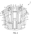
- Assembly 10 generally includes a fuel injector 12 disposed within an injector sleeve 14, which in turn is disposed within an injector bore 16 formed in a cylinder head 18.
- Cylinder head 18 includes a coolant passage 20 in fluid communication with injector bore 16.
- a retaining ring 22 may be positioned in the lower portion of sleeve 14 to provide a lower seal of coolant passage 20 at an interface portion 24 having a bore sealing surface 26 as described in U.S. Patent No. 8,230,808 , entitled INJECTOR SEAL ASSEMBLY AND METHOD OF SEALING A COOLANT PASSAGE FROM AN INJECTOR, which is also owned by the present assignee.
- Sleeve 14 generally has a side wall 29 with a cylindrical or tubular shape formed of appropriate material to be slip fit into place in bore 16.
- sleeve 14 typically includes an annular groove 28 for receiving a seal ring 30 which may be made of an elastomeric material.
- seal ring 30 and annular groove 28 may be omitted, or replaced with a series of shallow grooves to enhance plasticity of the sleeve outer surface.
- the sleeve 14 is sized with an appropriate diameter to create a close fit, and is then typically rolled with a conventional rolling device to form a seal with bore 16 and create a slight locking feature of sleeve material into the coolant passage. In this manner, coolant passage 20 is separated from the annular chamber 32 between injector 12 and sleeve 14, which usually is filled with low pressure fuel.
- the upper end of sleeve 14 has a burnished area 34.
- seal ring 30 may degrade and leak. As indicated above, replacement/repair of seal ring 30 using conventional techniques may be expensive, time consuming and complicated.
- the present disclosure provides a technique and system for repairing the seal provided by seal ring 30 in the field without removing sleeve 14 and without replacing cylinder head 18.
- a retaining ring 36 is provided to repair the seal provided by seal ring 30. As shown generally in FIG. 2 , retaining ring 36 is positioned between fuel injector 12 and injector sleeve 14 to press outwardly against sleeve 14 to repair the seal earlier provided by the damaged/degraded seal ring 30.
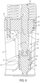
- retaining ring 36 is a generally ring-shaped component having a generally circular side wall 40 ( FIG. 3A ) defining a central opening 41.
- Side wall 40 includes a generally barrel-shaped outer surface 38 and a cylindrical inner surface 42 having a substantially constant cross-section.
- Outer surface 38 includes a curved upper portion 44 and a curved lower portion 46 connected by a central portion 48 with a less pronounced curvature.
- Side wall 40 further includes a substantially flat upper edge 45 and a substantially flat lower edge 47.
- Central opening 41 has a substantially constant diameter 53 between upper edge 45 and lower edge 47 of circular side wall 40.
- retaining ring 36 is formed from steel although other materials may be suitable in certain applications.
- retaining ring 36 may be inserted into sleeve 14 upper edge 45 first or lower edge 47 first.
- retaining ring 36 includes only one of curved upper portion 44 or curved lower portion 46.
- the edge 45, 47 corresponding to the curved portion provided must be installed first to permit the guiding and self-centering described herein.
- retaining ring 36 has an outer diameter 50 that is greater than an inner diameter 52 ( FIG. 2 ) of burnished area 34 of sleeve 14.
- outer diameter 50 is larger than inner diameter 52 by a distance in the range of 0.3 to 0.6 mm, and more preferably in the range of 0.35 to 0.5 mm.
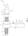
- Tool 54 generally includes a handle 56, a threaded drive rod 58 and a guide end 60.
- Handle 56 includes a body 62 having a mounting bore 64 that extends between an upper side 66 of body 62 to a lower side 68 of body 62 and a drive end 70 having a boss 72.
- a threaded opening 74 extends through drive end 70 and receives drive rod 58.
- Drive rod 58 includes a threaded body 76 having a drive head 78 at one end and a rotatable coupling 79 ( FIG. 6 ) at the end connected to guide end 60.
- Guide end 60 has an upper engagement boss 80, a cylindrical body 82 sized to receive retaining ring 36, and a tip 84 configured to bottom out in injector bore 16. As is further described below, when guide end 60 is fully inserted into injector sleeve 14, tip 84 limits the insertion distance and engagement boss 80 locates retaining ring 36 at the proper installed location. Although FIG. 6 shows tip 84 limiting travel when contacting the cylinder head and controlling the insertion depth of retaining ring 36, this feature is not necessary and may be replaced, in other embodiments, by a guide end 60 possessing a diameter slightly undersized from the injector bore and slightly oversized from the injector sleeve diameter to limit travel upon contacting the upper edge face of sleeve 14.
- Mounting bore 64 is positioned on handle body 62 to align with a threaded opening 90 adjacent injector bore 16 normally used to receive a bolt for attaching the injector hold down clamp (not shown).
- a bolt 92 is passed through mounting bore 64 and threaded into opening 90 until handle 56 is tightly attached to cylinder head 18.
- a tool such as a wrench is used to rotate drive head 78 of drive rod 58, thereby forcing guide end 60 downwardly into sleeve 14.
- engagement boss 80 of guide end 60 forces retaining ring 36 into sleeve 14.
- retaining ring 36 As retaining ring 36 engages the upper edge of sleeve 14, one of curved portions 44, 46 (depending on the orientation of ring 36) of outer surface 38 guides and centers retaining ring 36 into sleeve 14.
- Drive head 78 is further rotated until tip 84 of guide end 60 bottoms out in injector bore 16.
- retaining ring 36 is positioned at the proper depth in its installed position within sleeve 14, and its larger outer diameter relative to the inner diameter of sleeve 14 applies outwardly directed force that re-stablishes a seal between sleeve 14 and bore 16 where the failed seal ring 30 is located.
- retaining ring 36 could be removed from sleeve 14 using a suitable tool that engages the lower edge (45 or 47) of retaining ring 36 and applies upward force to pull retaining ring 36 out of sleeve 14.
- tool 154 for installing a retaining ring 36 into injector sleeve 14.
- tool 154 generally includes a handle 156, a threaded drive rod 158 and a guide end 160.
- Handle 156 includes a body 162 having a mounting bore 164 that extends between an upper side 166 of body 162 to a lower side 168 of body 162 and a drive end 170 having a boss 172.
- a cap screw 171 extends through mounting bore 164 to attach tool 154 to cylinder head 18.
- a threaded opening 174 extends through drive end 170 and receives drive rod 158.
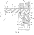
- Drive rod 158 includes a threaded body 176 having a drive head 178 at one end and a rotatable coupling 179 ( FIG. 9 ) at the end connected to guide end 160.
- Guide end 160 has an upper engagement boss 180, and a cylindrical body 182 sized to receive retaining ring 36.
- Drive rod 158 further includes a stop nut 184 that, in one embodiment, is attached in a fixed position on threaded body 176 adjacent drive head 178. As explained herein, as drive rod 158 is rotated using drive head 178, drive rod threads through drive end 170 of handle 156 and urges retaining ring 36 into injector bore 16.
- Stop nut 184 may be positioned on drive rod 158 to engage upper surface 166 of handle 156 to set the depth of insertion of retaining ring 36. In this manner, stop nut 184 provides for a repeatable insertion depth of retaining ring 36 and prevents over-tightening or under-tightening. In another embodiment, stop nut 184 may be adjustably positioned on drive rod 158 to provide for various different insertion depths.
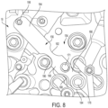
- Handle body 162 further includes a pair of forward recesses 186, 188 configured to provide clearance for valve springs as depicted in FIG. 8 when tool 154 is attached to cylinder head 18.
- Body 162 also has a pair of rearward recesses 190, 192 configured to provide clearance for cylinder head cap screws as shown in FIG. 8 .
- handle body 162 includes an extension 194 having a threaded opening 196.
- a threaded bolt 198 extends through opening 196 and is pivotally connected to a foot 200. As is further described herein, bolt 198 is used to tighten foot 200 into engagement with cylinder head 18 to counter-balance the force applied when drive rod 158 is threaded into injector bore 16.
- retaining ring 36 is inserted into sleeve 14 to repair the seal provided by seal ring 30 using tool 154 in the following manner.
- injector clamp (not shown) is removed, fuel injector 12 is removed from sleeve 14.
- a retaining ring 36 is placed onto body 182 of guide end 160 of tool 154.
- Guide end 160 (with retaining ring 36) is then inserted into injector bore 16 and positioned down into sleeve 14.
- Boss 172 of drive end 170 of handle 156 is positioned into injector bore 16 as shown in FIG. 9 to properly orient drive rod 158.
- Mounting bore 164 is positioned on handle body 162 to align with a threaded opening 202 adjacent injector bore 16 normally used to receive a bolt for attaching the injector hold down clamp (not shown).
- Cap screw 171 is passed through mounting bore 164 and threaded into opening 202 until handle 156 is tightly attached to cylinder head 18.
- Bolt 198 is then tightened to force foot 200 into engagement with cylinder head 18.
- a tool such as a wrench is used to rotate drive head 178 of drive rod 158, thereby forcing guide end 160 downwardly into sleeve 14.
- engagement boss 180 of guide end 160 forces retaining ring 36 into sleeve 14.
- one of curved portions 44, 46 (depending on the orientation of ring 36) of outer surface 38 guides and centers retaining ring 36 into sleeve 14.
- Drive head 178 is further rotated until stop nut 184 engages upper surface 166 of drive end 170.
- retaining ring 36 is positioned at the proper depth in its installed position within sleeve 14, and its larger outer diameter relative to the inner diameter of sleeve 14 applies outwardly directed force that re-stablishes a seal between sleeve 14 and bore 16 where the failed seal ring 30 is located. It should be understood that retaining ring 36 could be removed from sleeve 14 using a suitable tool that engages the lower edge (45 or 47) of retaining ring 36 and applies upward force to pull retaining ring 36 out of sleeve 14.
- reaction forces are directed upwardly, urging tool 154 approximately in direction A of FIG. 9 .
- This force may damage cap screw 171 or other components of tool 154.
- foot 200 of extension 194 engages cylinder head 18, a similar reaction force is generated, urging tool 154 approximately in direction B of FIG. 9 .
- This reaction force serves to counter balance the force in direction A, and inhibits damage to tool 154. In this manner, the life of tool 154 is extended such that it may be used repeatedly to install multiple retaining rings 36.
Landscapes
- Engineering & Computer Science (AREA)
- Mechanical Engineering (AREA)
- Chemical & Material Sciences (AREA)
- Combustion & Propulsion (AREA)
- General Engineering & Computer Science (AREA)
- Fuel-Injection Apparatus (AREA)
Claims (15)
- Verfahren zum Reparieren einer Dichtung zwischen einer Kraftstoffeinspritzdüsenhülse (14) und einer Kraftstoffeinspritzdüsenbohrung (16), umfassend:Entfernen einer Kraftstoffeinspritzdüse (12) aus der Kraftstoffeinspritzdüsenhülse (14), wobei die Kraftstoffeinspritzdüsenhülse (14) einen oberen Abschnitt aufweist, der eine Ringnut (28) zum Aufnehmen eines Dichtungsrings (30) umfasst;Installieren eines Halterings (36) in der Kraftstoffeinspritzdüsenbohrung (16), wobei der Haltering (36) eine Seitenwand (40) mit einer äußeren Oberfläche (38) aufweist, die einen gekrümmten Abschnitt neben mindestens einer Kante der Seitenwand enthält, um den Haltering (36) in die Kraftstoffeinspritzdüsenbohrung (16) einzuführen,Austauschen der Kraftstoffeinspritzdüse (12) in der Kraftstoffeinspritzdüsenhülse (14),wobei das Verfahren dadurch gekennzeichnet ist, dassder Haltering (36) ferner einen Außendurchmesser aufweist, der größer ist als ein Innendurchmesser des oberen Abschnitts der Kraftstoffeinspritzdüsenhülse (14) an einer Stelle neben einem oberen Dichtungsleck in dem oberen Abschnitt der Kraftstoffeinspritzdüsenhülse (14), sodass, wenn der Haltering (36) in einer installierten Position ist, der obere Abschnitt der Kraftstoffeinspritzdüsenhülse (14) nach außen zu der Kraftstoffeinspritzdüsenbohrung (16) hin verformt wird, um dadurch das obere Dichtungsleck zu reparieren.
- Verfahren nach Anspruch 1, wobei das Installieren des Halterings (36) das Platzieren des Halterings (36) auf einem Einführungswerkzeug (54), das Einführen des Einführungswerkzeugs (54) in die Kraftstoffeinspritzdüsenhülse (14) und das Verwenden des Einführungswerkzeugs (54) dazu, um den Haltering (36) in die installierte Position zu drängen, umfasst.
- Verfahren nach Anspruch 2, wobei das Verwenden des Einführungswerkzeugs (54) dazu, um den Haltering (36) in die installierte Position zu drängen, das Drehen einer Antriebsstange des Einführungswerkzeugs (54), um zu bewirken, dass ein runder Eingriffsansatz des Einführungswerkzeugs (54) den Haltering (36) in die Kraftstoffeinspritzdüsenhülse (14) drängt, bis eine an der Antriebsstange montierte Anschlagmutter in eine obere Oberfläche des Einführungswerkzeugs (54) eingreift, umfasst.
- Verfahren nach Anspruch 2, wobei das Installieren des Halterings (36) ferner das Befestigen des Einführungswerkzeugs (54) an einem Zylinderkopf (18), der die Kraftstoffeinspritzdüsenbohrung (16) bildet, umfasst, wobei das Befestigen des Einführungswerkzeugs (54) an dem Zylinderkopf (18) Folgendes umfasst:Positionieren einer Montagebohrung eines Griffkörpers des Einführungswerkzeugs (54), sodass sie auf eine Öffnung in dem Zylinderkopf (18) neben der Kraftstoffeinspritzdüsenbohrung (16) ausgerichtet ist;Einschrauben einer Kopfschraube durch die Montagebohrung in die Öffnung;und/oder Einschrauben einer Schraube durch eine Öffnung in einem Verlängerungsstück eines Griffkörpers des Einführungswerkzeugs (54), wodurch bewirkt wird, dass ein mit der Schraube verbundener Fuß in eine Oberfläche des Zylinderkopfs (18) eingreift.
- Verfahren nach Anspruch 1, wobei der gekrümmte Abschnitt der äußeren Oberfläche des Halterings (36) mindestens einen von einem oberen gekrümmten Abschnitt und einem unteren gekrümmten Abschnitt der äußeren Oberfläche und einen mittigen Abschnitt mit einer Krümmung enthält, die weniger ausgeprägt ist als der obere gekrümmte Abschnitt und der untere gekrümmte Abschnitt, sodass die äußere Oberfläche einer Tonne ähnelt.
- Verfahren nach Anspruch 5, wobei das Installieren des Halterings (36) das Zentrieren des Halterings (36) in der Kraftstoffeinspritzdüsenhülse (14) durch mindestens einen von dem oberen gekrümmten Abschnitt und dem unteren gekrümmten Abschnitt umfasst.
- Verfahren nach Anspruch 5, wobei sich der obere gekrümmte Abschnitt neben einer im Wesentlichen flachen oberen Kante des Halterings (36) und der untere gekrümmte Abschnitt neben einer im Wesentlichen flachen unteren Kante des Halterings (36) befindet.
- Verfahren nach Anspruch 1, wobei der Außendurchmesser des Halterings (36) um einen Abstand in einem Bereich von 0,3 bis 0,6 mm oder in einem Bereich von 0,35 bis 0,5 mm größer ist als der Innendurchmesser des oberen Abschnitts der Kraftstoffeinspritzdüsenhülse (14).
- Haltering (36) und Kraftstoffeinspritzdüsenhülse (14), wobei der Haltering (36) für eine Vor-Ort-Reparatur eines oberen Dichtungslecks der Kraftstoffeinspritzdüsenhülse (14) ausgestaltet ist, umfassend:die Kraftstoffeinspritzdüsenhülse (14), die einen oberen Abschnitt aufweist, der eine Ringnut (28) zum Aufnehmen eines Dichtungsrings (30) umfasst;den Haltering (36), der eine kreisförmige Seitenwand (40) mit einer tonnenförmigen äußeren Oberfläche (38) und einer im Wesentlichen zylinderförmigen inneren Oberfläche (42) umfasst; undwobei:die äußere Oberfläche (38) einen unteren gekrümmten Abschnitt (46) mit einer Krümmung und einen mittigen Abschnitt (48) mit einer Krümmung umfasst, die weniger ausgeprägt ist als die Krümmung des unteren gekrümmten Abschnitts; undwobei der untere gekrümmte Abschnitt (46) ausgestaltet ist, um den Haltering (36) in den oberen Abschnitt der Kraftstoffeinspritzdüsenhülse (14) einzuführen; undwobei der Haltering und die Kraftstoffeinspritzdüsenhülse dadurch gekennzeichnet sind, dass die kreisförmige Seitenwand (40) einen Außendurchmesser an dem mittigen Abschnitt (48) aufweist, der größer ist als ein Innendurchmesser des oberen Abschnitts der Kraftstoffeinspritzdüsenhülse (14) an einer Stelle eines oberen Dichtungslecks, sodass der Haltering (36) den oberen Abschnitt der Kraftstoffeinspritzdüsenhülse (14) an der Stelle des oberen Dichtungslecks in eine Verformung nach außen drängt, wenn der Haltering (36) in eine installierte Position bewegt wird.
- Haltering und Kraftstoffeinspritzdüsenhülse nach Anspruch 9, wobei:die kreisförmige Seitenwand (40) eine obere Kante zwischen der inneren Oberfläche und der äußeren Oberfläche (38) und eine untere Kante zwischen der inneren Oberfläche und der äußeren Oberfläche (38) umfasst;sich der untere gekrümmte Abschnitt (46) neben der unteren Kante der kreisförmigen Seitenwand (40) befindet; oder die kreisförmige Seitenwand (40) eine mittige Öffnung mit einem im Wesentlichen konstanten Durchmesser zwischen der oberen Kante und der unteren Kante definiert.
- Haltering und Kraftstoffeinspritzdüsenhülse nach Anspruch 9, wobei die äußere Oberfläche (38) ferner einen oberen gekrümmten Abschnitt neben der oberen Kante der kreisförmigen Seitenwand (40) umfasst.
- Haltering und Kraftstoffeinspritzdüsenhülse nach Anspruch 9, wobei der Außendurchmesser an dem mittigen Abschnitt um einen Abstand in einem Bereich von 0,3 bis 0,6 mm oder in einem Bereich von 0,35 bis 0,5 mm größer ist als der Innendurchmesser des oberen Abschnitts der Kraftstoffeinspritzdüsenhülse (14).
- System zur Vor-Ort-Reparatur eines oberen Dichtungslecks einer Kraftstoffeinspritzdüsenhülse (14), umfassend:einen Haltering (36) und eine Kraftstoffeinspritzdüsenhülse (14) nach Anspruch 9; undein Einführungswerkzeug (54), umfassend:einen Griff (56), der eine Montagebohrung (64) enthält, die ausgestaltet ist, um eine Kopfschraube (171) zum Montieren des Einführungswerkzeugs (54) an einem Zylinderkopf (18) eines Motors aufzunehmen;eine Gewindeantriebsstange (58), die einen Antriebskopf (78) enthält und mit dem Griff gekoppelt ist; undein mit der Gewindeantriebsstange (58) gekoppeltes Führungsende (60), wobei das Führungsende so ausgestaltet ist, dass es sich in die Kraftstoffeinspritzdüsenhülse (14) hinein und durch die mittige Öffnung (41) des Halterings (36) hindurch erstreckt,dadurch gekennzeichnet, dass das Führungsende einen runden Eingriffsansatz (80) aufweist, der den Haltering (36) als Reaktion auf eine Drehung des Antriebskopfs in eine installierte Position in dem oberen Abschnitt der Kraftstoffeinspritzdüsenhülse (14) drängt, wenn der Griff (56) an dem Zylinderkopf (18) montiert wird.
- System nach Anspruch 13, wobei die äußere Oberfläche ferner einen oberen gekrümmten Abschnitt mit einer Krümmung umfasst, die ausgeprägter ist als die Krümmung des mittigen Abschnitts.
- System nach Anspruch 13, wobei der Griff (56) des Einführungswerkzeugs (54) ein Verlängerungsstück mit einer Öffnung zum Aufnehmen einer Schraube enthält, die mit einem Fuß gekoppelt ist, der ausgestaltet ist, um in den Zylinderkopf (18) einzugreifen.
Applications Claiming Priority (2)
| Application Number | Priority Date | Filing Date | Title |
|---|---|---|---|
| US201662414996P | 2016-10-31 | 2016-10-31 | |
| PCT/US2017/038258 WO2018080598A1 (en) | 2016-10-31 | 2017-06-20 | Injector sleeve assembly and method for field repair procedure |
Publications (3)
| Publication Number | Publication Date |
|---|---|
| EP3516202A1 EP3516202A1 (de) | 2019-07-31 |
| EP3516202A4 EP3516202A4 (de) | 2020-06-10 |
| EP3516202B1 true EP3516202B1 (de) | 2024-08-21 |
Family
ID=62025310
Family Applications (1)
| Application Number | Title | Priority Date | Filing Date |
|---|---|---|---|
| EP17863497.8A Active EP3516202B1 (de) | 2016-10-31 | 2017-06-20 | Injektorhülsenanordnung und verfahren zur reparatur vor ort |
Country Status (4)
| Country | Link |
|---|---|
| US (1) | US11192210B2 (de) |
| EP (1) | EP3516202B1 (de) |
| CN (1) | CN110268154B (de) |
| WO (1) | WO2018080598A1 (de) |
Families Citing this family (8)
| Publication number | Priority date | Publication date | Assignee | Title |
|---|---|---|---|---|
| DE102017218007A1 (de) * | 2017-10-10 | 2019-04-11 | Robert Bosch Gmbh | Entkopplungselement für eine Brennstoffeinspritzvorrichtung |
| DE102017218002A1 (de) * | 2017-10-10 | 2019-04-11 | Robert Bosch Gmbh | Entkopplungselement für eine Brennstoffeinspritzvorrichtung |
| DE102017221203A1 (de) * | 2017-11-27 | 2019-05-29 | Hyundai Motor Company | Kraftstoffeinspritzsystem und Verfahren zum Betreiben eines Kraftstoffeinspritzsystems |
| DE102020214481A1 (de) * | 2020-11-18 | 2022-05-19 | Robert Bosch Gesellschaft mit beschränkter Haftung | Kraftstoffinjektor zur dosierten Abgabe von Kraftstoff |
| USD990520S1 (en) * | 2020-12-21 | 2023-06-27 | Shifukang Industrial Co., Ltd. | Base of fuel injector puller |
| DE102022209290A1 (de) * | 2022-09-07 | 2024-03-07 | Robert Bosch Gesellschaft mit beschränkter Haftung | Einspritzventil für Kraftstoffe, Zylinderkopf mit Einspritzventil, Verfahren zum Einbauen eines Einspritzventils in einen Zylinderkopf sowie Verwendung einer zylindrischen Aufnahme eines Zylinderkopfs als Außenhülle eines Einspritzventils |
| US12352229B2 (en) * | 2022-12-22 | 2025-07-08 | Robert Bosch Gmbh | Fuel injector dust seal |
| US20250354532A1 (en) * | 2024-05-14 | 2025-11-20 | Caterpillar Inc. | Fuel injector sleeve and engine system remanufacturing method using same |
Citations (1)
| Publication number | Priority date | Publication date | Assignee | Title |
|---|---|---|---|---|
| US20040069279A1 (en) * | 2001-07-07 | 2004-04-15 | Sieghart Maier | High-pressure fuel device |
Family Cites Families (20)
| Publication number | Priority date | Publication date | Assignee | Title |
|---|---|---|---|---|
| US3605703A (en) * | 1970-05-22 | 1971-09-20 | Gen Motors Corp | Fuel injection |
| US4018462A (en) | 1975-10-31 | 1977-04-19 | Hitachi Metals, Ltd. | Pipe fitting |
| JPS5565085A (en) * | 1978-11-07 | 1980-05-16 | Akito Shigeoka | Drawing tool of fuel injection valve in diesel engine |
| US5345913A (en) | 1993-11-24 | 1994-09-13 | Caterpillar Inc. | Injector assembly |
| US6289876B1 (en) * | 1999-03-29 | 2001-09-18 | International Truck And Engine Corporation | Fuel injector |
| DE10108194A1 (de) | 2001-02-21 | 2002-08-29 | Bosch Gmbh Robert | Dichtvorrichtung für ein Brennstoffeinspritzventil |
| US6866026B2 (en) * | 2002-08-28 | 2005-03-15 | Federal-Mogul World Wide, Inc. | Gasket for fuel injector |
| US7551705B2 (en) * | 2003-12-11 | 2009-06-23 | Areva Np, Inc. | Fuel assembly top nozzle repair sleeve and method for repairing a fuel assembly |
| CN101675241B (zh) * | 2007-05-02 | 2014-12-17 | 罗伯特·博世有限公司 | 具有用于燃料喷射阀的密封装置保护的内燃机 |
| US8061142B2 (en) * | 2008-04-11 | 2011-11-22 | General Electric Company | Mixer for a combustor |
| US8490263B2 (en) * | 2008-08-28 | 2013-07-23 | Whitaker Tools, Inc. | Injector sleeve removal tool |
| DE112010003755B4 (de) * | 2009-09-23 | 2015-06-18 | Cummins Intellectual Properties, Inc. | Einspritzdüsenabdichtungsaufbau und Verfahren zum Abdichten eines Kühlkanals zu einer Einspritzdüse |
| US9382887B2 (en) | 2009-09-23 | 2016-07-05 | Cummins Intellectual Property. Inc. | Engine component seal assembly and method of sealing a coolant passage from an engine component |
| TW201239222A (en) * | 2010-12-06 | 2012-10-01 | Microflex Technologies Llc | Ring seal retainer assembly and methods |
| DE202010016349U1 (de) * | 2010-12-08 | 2011-03-17 | Sauer Spezialwerkzeug Gmbh | Werkzeug zum Lösen von festsitzenden Verbindungen |
| US9370845B2 (en) | 2013-07-19 | 2016-06-21 | Cummins Inc. | Method of repairing a cracked head using an injector bore insert |
| US9410520B2 (en) * | 2013-08-08 | 2016-08-09 | Cummins Inc. | Internal combustion engine including an injector combustion seal positioned between a fuel injector and an engine body |
| US9364924B2 (en) | 2013-10-11 | 2016-06-14 | Kennieth Neal | Method and apparatus for repairing a cylinder head |
| CN103753487B (zh) * | 2014-01-17 | 2016-04-20 | 德清方山五金工具有限公司 | 柴油发动机喷油嘴隔水套拆卸器 |
| US10471554B2 (en) * | 2017-08-22 | 2019-11-12 | Caterpillar Inc. | Fuel injector bore repair |
-
2017
- 2017-06-20 US US16/346,272 patent/US11192210B2/en active Active
- 2017-06-20 WO PCT/US2017/038258 patent/WO2018080598A1/en not_active Ceased
- 2017-06-20 CN CN201780065911.4A patent/CN110268154B/zh active Active
- 2017-06-20 EP EP17863497.8A patent/EP3516202B1/de active Active
Patent Citations (1)
| Publication number | Priority date | Publication date | Assignee | Title |
|---|---|---|---|---|
| US20040069279A1 (en) * | 2001-07-07 | 2004-04-15 | Sieghart Maier | High-pressure fuel device |
Also Published As
| Publication number | Publication date |
|---|---|
| US11192210B2 (en) | 2021-12-07 |
| CN110268154B (zh) | 2026-03-17 |
| EP3516202A1 (de) | 2019-07-31 |
| WO2018080598A1 (en) | 2018-05-03 |
| CN110268154A (zh) | 2019-09-20 |
| US20190255664A1 (en) | 2019-08-22 |
| EP3516202A4 (de) | 2020-06-10 |
Similar Documents
| Publication | Publication Date | Title |
|---|---|---|
| EP3516202B1 (de) | Injektorhülsenanordnung und verfahren zur reparatur vor ort | |
| US20200080661A1 (en) | Hydraulic fluid pump and retainer assembly for same | |
| US7617712B2 (en) | Alignment device and methods of using the same | |
| US4324407A (en) | Pressure actuated metal-to-metal seal | |
| US20240401552A1 (en) | Injector cup for engines apparatus and methods of use | |
| US6969071B2 (en) | Face seal assembly | |
| CN112192499A (zh) | 高压油泵柱塞组合式o形密封圈安装工装及安装方法 | |
| US4913464A (en) | Tubular joint with seal | |
| US9382871B2 (en) | Method for repair of cylinder block including water ferrule | |
| US7845619B2 (en) | Two-part back cap for a plug valve and plug valves incorporating same | |
| US20170276269A1 (en) | Pipe connector | |
| MX2013012073A (es) | Aparato y metodo para empalmar conductos y mangueras submarinas. | |
| CN121803378A (zh) | 用于现场修复过程的喷射器套筒组件和方法 | |
| CA2324175A1 (en) | Swivel coupling and meyhod for attaching a swivel nut to a tail piece | |
| KR102842370B1 (ko) | 실린더 블록 헤드볼트의 볼트홀 복원방법 | |
| US11905947B2 (en) | Fluid end of a hydraulic fluid pump and method of assembling the same | |
| US12215801B2 (en) | Valve packing apparatus and related methods | |
| CN117730211B (zh) | 安装拆卸组件、轴和轴承组件、安装方法及拆卸方法 | |
| US20110044783A1 (en) | Retainer Apparatus | |
| US20230066412A1 (en) | Installation tool | |
| CA2546160C (en) | Two-part back cap for a plug valve and plug valves incorporating same | |
| CN120312907A (zh) | 一种分步式海底管道连接器 |
Legal Events
| Date | Code | Title | Description |
|---|---|---|---|
| STAA | Information on the status of an ep patent application or granted ep patent |
Free format text: STATUS: THE INTERNATIONAL PUBLICATION HAS BEEN MADE |
|
| PUAI | Public reference made under article 153(3) epc to a published international application that has entered the european phase |
Free format text: ORIGINAL CODE: 0009012 |
|
| STAA | Information on the status of an ep patent application or granted ep patent |
Free format text: STATUS: REQUEST FOR EXAMINATION WAS MADE |
|
| 17P | Request for examination filed |
Effective date: 20190425 |
|
| AK | Designated contracting states |
Kind code of ref document: A1 Designated state(s): AL AT BE BG CH CY CZ DE DK EE ES FI FR GB GR HR HU IE IS IT LI LT LU LV MC MK MT NL NO PL PT RO RS SE SI SK SM TR |
|
| REG | Reference to a national code |
Ipc: B25B0027000000 Ref country code: DE Ref legal event code: R079 Ref document number: 602017084318 Country of ref document: DE Free format text: PREVIOUS MAIN CLASS: F02M0061160000 Ipc: B25B0027000000 |
|
| A4 | Supplementary search report drawn up and despatched |
Effective date: 20200511 |
|
| RIC1 | Information provided on ipc code assigned before grant |
Ipc: B25B 23/00 20060101ALI20200504BHEP Ipc: F02M 61/14 20060101ALI20200504BHEP Ipc: F02M 53/04 20060101ALI20200504BHEP Ipc: F02M 53/00 20060101ALI20200504BHEP Ipc: B23P 6/00 20060101ALI20200504BHEP Ipc: F02F 11/00 20060101ALI20200504BHEP Ipc: B25B 27/00 20060101AFI20200504BHEP Ipc: B23P 6/04 20060101ALI20200504BHEP |
|
| STAA | Information on the status of an ep patent application or granted ep patent |
Free format text: STATUS: EXAMINATION IS IN PROGRESS |
|
| 17Q | First examination report despatched |
Effective date: 20220304 |
|
| GRAP | Despatch of communication of intention to grant a patent |
Free format text: ORIGINAL CODE: EPIDOSNIGR1 |
|
| STAA | Information on the status of an ep patent application or granted ep patent |
Free format text: STATUS: GRANT OF PATENT IS INTENDED |
|
| INTG | Intention to grant announced |
Effective date: 20230418 |
|
| P01 | Opt-out of the competence of the unified patent court (upc) registered |
Effective date: 20230510 |
|
| GRAJ | Information related to disapproval of communication of intention to grant by the applicant or resumption of examination proceedings by the epo deleted |
Free format text: ORIGINAL CODE: EPIDOSDIGR1 |
|
| STAA | Information on the status of an ep patent application or granted ep patent |
Free format text: STATUS: EXAMINATION IS IN PROGRESS |
|
| INTC | Intention to grant announced (deleted) | ||
| GRAP | Despatch of communication of intention to grant a patent |
Free format text: ORIGINAL CODE: EPIDOSNIGR1 |
|
| STAA | Information on the status of an ep patent application or granted ep patent |
Free format text: STATUS: GRANT OF PATENT IS INTENDED |
|
| INTG | Intention to grant announced |
Effective date: 20231102 |
|
| GRAJ | Information related to disapproval of communication of intention to grant by the applicant or resumption of examination proceedings by the epo deleted |
Free format text: ORIGINAL CODE: EPIDOSDIGR1 |
|
| STAA | Information on the status of an ep patent application or granted ep patent |
Free format text: STATUS: EXAMINATION IS IN PROGRESS |
|
| GRAP | Despatch of communication of intention to grant a patent |
Free format text: ORIGINAL CODE: EPIDOSNIGR1 |
|
| STAA | Information on the status of an ep patent application or granted ep patent |
Free format text: STATUS: GRANT OF PATENT IS INTENDED |
|
| INTC | Intention to grant announced (deleted) | ||
| INTG | Intention to grant announced |
Effective date: 20240313 |
|
| GRAS | Grant fee paid |
Free format text: ORIGINAL CODE: EPIDOSNIGR3 |
|
| GRAA | (expected) grant |
Free format text: ORIGINAL CODE: 0009210 |
|
| STAA | Information on the status of an ep patent application or granted ep patent |
Free format text: STATUS: THE PATENT HAS BEEN GRANTED |
|
| AK | Designated contracting states |
Kind code of ref document: B1 Designated state(s): AL AT BE BG CH CY CZ DE DK EE ES FI FR GB GR HR HU IE IS IT LI LT LU LV MC MK MT NL NO PL PT RO RS SE SI SK SM TR |
|
| REG | Reference to a national code |
Ref country code: GB Ref legal event code: FG4D |
|
| REG | Reference to a national code |
Ref country code: CH Ref legal event code: EP |
|
| REG | Reference to a national code |
Ref country code: IE Ref legal event code: FG4D |
|
| REG | Reference to a national code |
Ref country code: DE Ref legal event code: R096 Ref document number: 602017084318 Country of ref document: DE |
|
| REG | Reference to a national code |
Ref country code: LT Ref legal event code: MG9D |
|
| REG | Reference to a national code |
Ref country code: NL Ref legal event code: MP Effective date: 20240821 |
|
| PG25 | Lapsed in a contracting state [announced via postgrant information from national office to epo] |
Ref country code: NO Free format text: LAPSE BECAUSE OF FAILURE TO SUBMIT A TRANSLATION OF THE DESCRIPTION OR TO PAY THE FEE WITHIN THE PRESCRIBED TIME-LIMIT Effective date: 20241121 |
|
| REG | Reference to a national code |
Ref country code: AT Ref legal event code: MK05 Ref document number: 1715085 Country of ref document: AT Kind code of ref document: T Effective date: 20240821 |
|
| PG25 | Lapsed in a contracting state [announced via postgrant information from national office to epo] |
Ref country code: NL Free format text: LAPSE BECAUSE OF FAILURE TO SUBMIT A TRANSLATION OF THE DESCRIPTION OR TO PAY THE FEE WITHIN THE PRESCRIBED TIME-LIMIT Effective date: 20240821 Ref country code: PT Free format text: LAPSE BECAUSE OF FAILURE TO SUBMIT A TRANSLATION OF THE DESCRIPTION OR TO PAY THE FEE WITHIN THE PRESCRIBED TIME-LIMIT Effective date: 20241223 Ref country code: GR Free format text: LAPSE BECAUSE OF FAILURE TO SUBMIT A TRANSLATION OF THE DESCRIPTION OR TO PAY THE FEE WITHIN THE PRESCRIBED TIME-LIMIT Effective date: 20241122 Ref country code: FI Free format text: LAPSE BECAUSE OF FAILURE TO SUBMIT A TRANSLATION OF THE DESCRIPTION OR TO PAY THE FEE WITHIN THE PRESCRIBED TIME-LIMIT Effective date: 20240821 Ref country code: PL Free format text: LAPSE BECAUSE OF FAILURE TO SUBMIT A TRANSLATION OF THE DESCRIPTION OR TO PAY THE FEE WITHIN THE PRESCRIBED TIME-LIMIT Effective date: 20240821 |
|
| PG25 | Lapsed in a contracting state [announced via postgrant information from national office to epo] |
Ref country code: BG Free format text: LAPSE BECAUSE OF FAILURE TO SUBMIT A TRANSLATION OF THE DESCRIPTION OR TO PAY THE FEE WITHIN THE PRESCRIBED TIME-LIMIT Effective date: 20240821 |
|
| PG25 | Lapsed in a contracting state [announced via postgrant information from national office to epo] |
Ref country code: LV Free format text: LAPSE BECAUSE OF FAILURE TO SUBMIT A TRANSLATION OF THE DESCRIPTION OR TO PAY THE FEE WITHIN THE PRESCRIBED TIME-LIMIT Effective date: 20240821 |
|
| PG25 | Lapsed in a contracting state [announced via postgrant information from national office to epo] |
Ref country code: IS Free format text: LAPSE BECAUSE OF FAILURE TO SUBMIT A TRANSLATION OF THE DESCRIPTION OR TO PAY THE FEE WITHIN THE PRESCRIBED TIME-LIMIT Effective date: 20241221 Ref country code: AT Free format text: LAPSE BECAUSE OF FAILURE TO SUBMIT A TRANSLATION OF THE DESCRIPTION OR TO PAY THE FEE WITHIN THE PRESCRIBED TIME-LIMIT Effective date: 20240821 |
|
| PG25 | Lapsed in a contracting state [announced via postgrant information from national office to epo] |
Ref country code: HR Free format text: LAPSE BECAUSE OF FAILURE TO SUBMIT A TRANSLATION OF THE DESCRIPTION OR TO PAY THE FEE WITHIN THE PRESCRIBED TIME-LIMIT Effective date: 20240821 |
|
| PG25 | Lapsed in a contracting state [announced via postgrant information from national office to epo] |
Ref country code: ES Free format text: LAPSE BECAUSE OF FAILURE TO SUBMIT A TRANSLATION OF THE DESCRIPTION OR TO PAY THE FEE WITHIN THE PRESCRIBED TIME-LIMIT Effective date: 20240821 Ref country code: RS Free format text: LAPSE BECAUSE OF FAILURE TO SUBMIT A TRANSLATION OF THE DESCRIPTION OR TO PAY THE FEE WITHIN THE PRESCRIBED TIME-LIMIT Effective date: 20241121 |
|
| PG25 | Lapsed in a contracting state [announced via postgrant information from national office to epo] |
Ref country code: RS Free format text: LAPSE BECAUSE OF FAILURE TO SUBMIT A TRANSLATION OF THE DESCRIPTION OR TO PAY THE FEE WITHIN THE PRESCRIBED TIME-LIMIT Effective date: 20241121 Ref country code: PT Free format text: LAPSE BECAUSE OF FAILURE TO SUBMIT A TRANSLATION OF THE DESCRIPTION OR TO PAY THE FEE WITHIN THE PRESCRIBED TIME-LIMIT Effective date: 20241223 Ref country code: PL Free format text: LAPSE BECAUSE OF FAILURE TO SUBMIT A TRANSLATION OF THE DESCRIPTION OR TO PAY THE FEE WITHIN THE PRESCRIBED TIME-LIMIT Effective date: 20240821 Ref country code: NO Free format text: LAPSE BECAUSE OF FAILURE TO SUBMIT A TRANSLATION OF THE DESCRIPTION OR TO PAY THE FEE WITHIN THE PRESCRIBED TIME-LIMIT Effective date: 20241121 Ref country code: NL Free format text: LAPSE BECAUSE OF FAILURE TO SUBMIT A TRANSLATION OF THE DESCRIPTION OR TO PAY THE FEE WITHIN THE PRESCRIBED TIME-LIMIT Effective date: 20240821 Ref country code: LV Free format text: LAPSE BECAUSE OF FAILURE TO SUBMIT A TRANSLATION OF THE DESCRIPTION OR TO PAY THE FEE WITHIN THE PRESCRIBED TIME-LIMIT Effective date: 20240821 Ref country code: IS Free format text: LAPSE BECAUSE OF FAILURE TO SUBMIT A TRANSLATION OF THE DESCRIPTION OR TO PAY THE FEE WITHIN THE PRESCRIBED TIME-LIMIT Effective date: 20241221 Ref country code: HR Free format text: LAPSE BECAUSE OF FAILURE TO SUBMIT A TRANSLATION OF THE DESCRIPTION OR TO PAY THE FEE WITHIN THE PRESCRIBED TIME-LIMIT Effective date: 20240821 Ref country code: GR Free format text: LAPSE BECAUSE OF FAILURE TO SUBMIT A TRANSLATION OF THE DESCRIPTION OR TO PAY THE FEE WITHIN THE PRESCRIBED TIME-LIMIT Effective date: 20241122 Ref country code: FI Free format text: LAPSE BECAUSE OF FAILURE TO SUBMIT A TRANSLATION OF THE DESCRIPTION OR TO PAY THE FEE WITHIN THE PRESCRIBED TIME-LIMIT Effective date: 20240821 Ref country code: ES Free format text: LAPSE BECAUSE OF FAILURE TO SUBMIT A TRANSLATION OF THE DESCRIPTION OR TO PAY THE FEE WITHIN THE PRESCRIBED TIME-LIMIT Effective date: 20240821 Ref country code: BG Free format text: LAPSE BECAUSE OF FAILURE TO SUBMIT A TRANSLATION OF THE DESCRIPTION OR TO PAY THE FEE WITHIN THE PRESCRIBED TIME-LIMIT Effective date: 20240821 Ref country code: AT Free format text: LAPSE BECAUSE OF FAILURE TO SUBMIT A TRANSLATION OF THE DESCRIPTION OR TO PAY THE FEE WITHIN THE PRESCRIBED TIME-LIMIT Effective date: 20240821 |
|
| PG25 | Lapsed in a contracting state [announced via postgrant information from national office to epo] |
Ref country code: SM Free format text: LAPSE BECAUSE OF FAILURE TO SUBMIT A TRANSLATION OF THE DESCRIPTION OR TO PAY THE FEE WITHIN THE PRESCRIBED TIME-LIMIT Effective date: 20240821 Ref country code: DK Free format text: LAPSE BECAUSE OF FAILURE TO SUBMIT A TRANSLATION OF THE DESCRIPTION OR TO PAY THE FEE WITHIN THE PRESCRIBED TIME-LIMIT Effective date: 20240821 Ref country code: RO Free format text: LAPSE BECAUSE OF FAILURE TO SUBMIT A TRANSLATION OF THE DESCRIPTION OR TO PAY THE FEE WITHIN THE PRESCRIBED TIME-LIMIT Effective date: 20240821 |
|
| PG25 | Lapsed in a contracting state [announced via postgrant information from national office to epo] |
Ref country code: EE Free format text: LAPSE BECAUSE OF FAILURE TO SUBMIT A TRANSLATION OF THE DESCRIPTION OR TO PAY THE FEE WITHIN THE PRESCRIBED TIME-LIMIT Effective date: 20240821 |
|
| PG25 | Lapsed in a contracting state [announced via postgrant information from national office to epo] |
Ref country code: CZ Free format text: LAPSE BECAUSE OF FAILURE TO SUBMIT A TRANSLATION OF THE DESCRIPTION OR TO PAY THE FEE WITHIN THE PRESCRIBED TIME-LIMIT Effective date: 20240821 |
|
| PG25 | Lapsed in a contracting state [announced via postgrant information from national office to epo] |
Ref country code: IT Free format text: LAPSE BECAUSE OF FAILURE TO SUBMIT A TRANSLATION OF THE DESCRIPTION OR TO PAY THE FEE WITHIN THE PRESCRIBED TIME-LIMIT Effective date: 20240821 Ref country code: SK Free format text: LAPSE BECAUSE OF FAILURE TO SUBMIT A TRANSLATION OF THE DESCRIPTION OR TO PAY THE FEE WITHIN THE PRESCRIBED TIME-LIMIT Effective date: 20240821 |
|
| REG | Reference to a national code |
Ref country code: DE Ref legal event code: R097 Ref document number: 602017084318 Country of ref document: DE |
|
| PLBE | No opposition filed within time limit |
Free format text: ORIGINAL CODE: 0009261 |
|
| STAA | Information on the status of an ep patent application or granted ep patent |
Free format text: STATUS: NO OPPOSITION FILED WITHIN TIME LIMIT |
|
| PGFP | Annual fee paid to national office [announced via postgrant information from national office to epo] |
Ref country code: DE Payment date: 20250627 Year of fee payment: 9 |
|
| 26N | No opposition filed |
Effective date: 20250522 |
|
| PG25 | Lapsed in a contracting state [announced via postgrant information from national office to epo] |
Ref country code: SE Free format text: LAPSE BECAUSE OF FAILURE TO SUBMIT A TRANSLATION OF THE DESCRIPTION OR TO PAY THE FEE WITHIN THE PRESCRIBED TIME-LIMIT Effective date: 20240821 |
|
| REG | Reference to a national code |
Ref country code: CH Ref legal event code: H13 Free format text: ST27 STATUS EVENT CODE: U-0-0-H10-H13 (AS PROVIDED BY THE NATIONAL OFFICE) Effective date: 20260127 |
|
| PG25 | Lapsed in a contracting state [announced via postgrant information from national office to epo] |
Ref country code: MC Free format text: LAPSE BECAUSE OF FAILURE TO SUBMIT A TRANSLATION OF THE DESCRIPTION OR TO PAY THE FEE WITHIN THE PRESCRIBED TIME-LIMIT Effective date: 20240821 |
|
| PG25 | Lapsed in a contracting state [announced via postgrant information from national office to epo] |
Ref country code: LU Free format text: LAPSE BECAUSE OF NON-PAYMENT OF DUE FEES Effective date: 20250620 |
|
| GBPC | Gb: european patent ceased through non-payment of renewal fee |
Effective date: 20250620 |
|
| REG | Reference to a national code |
Ref country code: BE Ref legal event code: MM Effective date: 20250630 |