EP3514945B1 - Methods of fault detection in an electrical machine, electrical machines and wind turbines - Google Patents
Methods of fault detection in an electrical machine, electrical machines and wind turbines Download PDFInfo
- Publication number
- EP3514945B1 EP3514945B1 EP18382035.6A EP18382035A EP3514945B1 EP 3514945 B1 EP3514945 B1 EP 3514945B1 EP 18382035 A EP18382035 A EP 18382035A EP 3514945 B1 EP3514945 B1 EP 3514945B1
- Authority
- EP
- European Patent Office
- Prior art keywords
- rotor
- coils
- stator
- fault
- electrical machine
- Prior art date
- Legal status (The legal status is an assumption and is not a legal conclusion. Google has not performed a legal analysis and makes no representation as to the accuracy of the status listed.)
- Active
Links
- 238000000034 method Methods 0.000 title claims description 63
- 238000001514 detection method Methods 0.000 title claims description 30
- 230000005347 demagnetization Effects 0.000 claims description 8
- 238000012545 processing Methods 0.000 claims description 7
- 238000013507 mapping Methods 0.000 claims description 4
- 230000009467 reduction Effects 0.000 description 7
- 238000013459 approach Methods 0.000 description 3
- 230000004907 flux Effects 0.000 description 3
- 238000005259 measurement Methods 0.000 description 3
- 238000012544 monitoring process Methods 0.000 description 3
- 230000009471 action Effects 0.000 description 2
- 238000004364 calculation method Methods 0.000 description 2
- 238000004891 communication Methods 0.000 description 2
- 238000000354 decomposition reaction Methods 0.000 description 2
- 238000003745 diagnosis Methods 0.000 description 2
- 238000010586 diagram Methods 0.000 description 2
- 230000010354 integration Effects 0.000 description 2
- 230000035945 sensitivity Effects 0.000 description 2
- 230000009466 transformation Effects 0.000 description 2
- 230000007423 decrease Effects 0.000 description 1
- 238000013461 design Methods 0.000 description 1
- 230000006870 function Effects 0.000 description 1
- 238000012423 maintenance Methods 0.000 description 1
- 230000008569 process Effects 0.000 description 1
- 238000004804 winding Methods 0.000 description 1
Images


Classifications
-
- H—ELECTRICITY
- H02—GENERATION; CONVERSION OR DISTRIBUTION OF ELECTRIC POWER
- H02P—CONTROL OR REGULATION OF ELECTRIC MOTORS, ELECTRIC GENERATORS OR DYNAMO-ELECTRIC CONVERTERS; CONTROLLING TRANSFORMERS, REACTORS OR CHOKE COILS
- H02P9/00—Arrangements for controlling electric generators for the purpose of obtaining a desired output
- H02P9/10—Control effected upon generator excitation circuit to reduce harmful effects of overloads or transients, e.g. sudden application of load, sudden removal of load, sudden change of load
- H02P9/12—Control effected upon generator excitation circuit to reduce harmful effects of overloads or transients, e.g. sudden application of load, sudden removal of load, sudden change of load for demagnetising; for reducing effects of remanence; for preventing pole reversal
-
- H—ELECTRICITY
- H02—GENERATION; CONVERSION OR DISTRIBUTION OF ELECTRIC POWER
- H02P—CONTROL OR REGULATION OF ELECTRIC MOTORS, ELECTRIC GENERATORS OR DYNAMO-ELECTRIC CONVERTERS; CONTROLLING TRANSFORMERS, REACTORS OR CHOKE COILS
- H02P29/00—Arrangements for regulating or controlling electric motors, appropriate for both AC and DC motors
- H02P29/02—Providing protection against overload without automatic interruption of supply
- H02P29/024—Detecting a fault condition, e.g. short circuit, locked rotor, open circuit or loss of load
- H02P29/0241—Detecting a fault condition, e.g. short circuit, locked rotor, open circuit or loss of load the fault being an overvoltage
-
- H—ELECTRICITY
- H02—GENERATION; CONVERSION OR DISTRIBUTION OF ELECTRIC POWER
- H02P—CONTROL OR REGULATION OF ELECTRIC MOTORS, ELECTRIC GENERATORS OR DYNAMO-ELECTRIC CONVERTERS; CONTROLLING TRANSFORMERS, REACTORS OR CHOKE COILS
- H02P2101/00—Special adaptation of control arrangements for generators
- H02P2101/15—Special adaptation of control arrangements for generators for wind-driven turbines
-
- H—ELECTRICITY
- H02—GENERATION; CONVERSION OR DISTRIBUTION OF ELECTRIC POWER
- H02P—CONTROL OR REGULATION OF ELECTRIC MOTORS, ELECTRIC GENERATORS OR DYNAMO-ELECTRIC CONVERTERS; CONTROLLING TRANSFORMERS, REACTORS OR CHOKE COILS
- H02P2207/00—Indexing scheme relating to controlling arrangements characterised by the type of motor
- H02P2207/05—Synchronous machines, e.g. with permanent magnets or DC excitation
-
- Y—GENERAL TAGGING OF NEW TECHNOLOGICAL DEVELOPMENTS; GENERAL TAGGING OF CROSS-SECTIONAL TECHNOLOGIES SPANNING OVER SEVERAL SECTIONS OF THE IPC; TECHNICAL SUBJECTS COVERED BY FORMER USPC CROSS-REFERENCE ART COLLECTIONS [XRACs] AND DIGESTS
- Y02—TECHNOLOGIES OR APPLICATIONS FOR MITIGATION OR ADAPTATION AGAINST CLIMATE CHANGE
- Y02E—REDUCTION OF GREENHOUSE GAS [GHG] EMISSIONS, RELATED TO ENERGY GENERATION, TRANSMISSION OR DISTRIBUTION
- Y02E10/00—Energy generation through renewable energy sources
- Y02E10/70—Wind energy
- Y02E10/72—Wind turbines with rotation axis in wind direction
Definitions
- the present disclosure relates to methods of fault detection in an electrical machine and further relates to electrical machines.
- the disclosure also relates to wind turbines.
- Electrical machines such as motors and generators, generally comprise a rotor structure and a stator structure.
- PM permanent magnet excited generators
- winding elements e.g. coils
- coils may be connected in series, in parallel or a combination of both, some coils connected in series in several parallel branches, see for example US2011/0316464 A1 .
- Permanent magnet generators are generally deemed to be reliable and require less maintenance than other generator typologies. Permanent magnet generators may be used for example in wind turbines, and also in offshore wind turbines. Wind turbines of this kind generally comprise a rotor with a rotor hub and a plurality of blades. The rotor is set into rotation under the influence of the wind on the blades. The rotation of the rotor shaft drives the rotor of the electrical machine as a generator either directly (“directly driven") or through the use of a gearbox.
- faults In electrical machines, particularly permanent magnet generators which can be used in wind turbines, there are several fault types that may occur. Examples of those faults are eccentricities of the rotor, airgap deformations between rotor and stator, and magnet faults such as demagnetization or broken/detached magnet(s).
- Fault diagnosis has an important role in a reliable operation of an electrical machine.
- Airgap deformation and eccentricities may cause a higher structural stress and mechanical problems which can be potentially catastrophic faults with increased operational costs.
- a detached or broken magnet may cause a loss of electromagnetic force.
- a detached or broken magnet may cause a loss of parts to the airgap between rotor and stator and thus severe mechanical problems may occur.
- demagnetization may occur because of a stator short-circuit or an improper connection of a coil (among others), if a demagnetized pole is not detected (and not replaced), current in the stator may increase to compensate reduced back-emf (back electromotive force), which can lead to higher losses and higher temperatures. Performance of the generator can thus be reduced.
- Eccentricity of the rotor and airgap deformation faults are usually measured by airgap sensors placed on a stator tooth and a rotor pole.
- those sensors require more complex integration in the electrical machine, since they need to be directly placed in the airgap, see for example " 2-Pole turbo-generator eccentricity diagnosis by split-phase current signature analysis", C. Bruzzese, 2013 9th IEEE International Symposium on Diagnostics for Electric Machines, Power Electronics and Drives (SDEMPED),XP032514154 .
- magnet faults may be indirectly detected by current or phase voltage monitoring.
- the increased current to compensate reduced back-emf requires using a complex signal processing to detect a magnet fault.
- this current or phase voltage monitoring solution may not detect incipient faults, since stator (or rotor) currents and voltage signals are not directly affected by the magnet fault.
- the present disclosure provides examples of methods and devices that at least partially resolve some of the aforementioned disadvantages.
- the present invention is defined by a method of fault detection according to claim 1 and a wind turbine according to claim 14.
- a method of fault detection in an electrical machine has a rotor and a stator, one of the rotor and stator having at least two coils connected in series.
- the method comprises measuring a voltage over a single coil of the two coils connected in series.
- the method further comprises determining a fault condition based at least on the measured voltage over time.
- a method with an enhanced sensitivity to fault detection is obtained with respect to the known solutions since voltage of a single coil is directly affected by the faults, rather than an indirect measurement of total phase current or total phase voltage.
- the single coil voltage in coils connected in series is less sensitive to circulating currents in the coils which compensate reduced back-emf.
- the enhanced sensitivity also allows for incipient fault detection (magnet fault, eccentricity, airgap deformation, etc.), which can avoid potential catastrophic faults and thus the operational cost.
- airgap sensors with complex integration in the electrical machine are not needed to determine an airgap deformation fault.
- Figure 1 illustrates a perspective view of one example of a wind turbine 160.
- the wind turbine 160 includes a tower 170 extending from a support surface 150, a nacelle 161 mounted on the tower 170, and a rotor 115 coupled to the nacelle 161.
- the rotor 115 includes a rotatable hub 110 and at least one rotor blade 120 coupled to and extending outwardly from the hub 110.
- the rotor 115 includes three rotor blades 120.
- the rotor 115 may include more or less than three rotor blades 120.
- Each rotor blade 120 may be spaced about the hub 110 to facilitate rotating the rotor 115 to enable kinetic energy to be transferred from the wind into usable mechanical energy, and subsequently, electrical energy.
- the hub 110 may be rotatably coupled to an electric generator.
- This electric generator is an example of electrical machine 1, as illustrated in Figure 2 , positioned within the nacelle 161 to permit electrical energy to be produced.
- FIG. 2 schematically represents a rotor 2 and a stator 3 of an electrical machine 1 according to one example.
- This electrical machine 1 may be a direct drive wind turbine generator which may be disposed within the nacelle 161.
- the electrical machine 1 comprises the rotor 2 and the stator 3 and the rotor 2 may comprise a plurality of magnets m1, m2, m3, m4.
- the plurality of magnets are arranged to consecutively face coils a1, a2, a3, a4 of the stator 3 when the rotor is driven.
- the rotor is set into rotation by rotation of the rotor (which in turn is rotated under the action of the wind) so as to generate electrical energy.
- coils may be arranged in the rotor 2 and magnets in the stator 3.
- the magnets m1, m2, m3, m4 are permanent magnets.
- the electrical machine may be a motor.
- One of the rotor 2 and stator 3 comprises two coils connected in series.
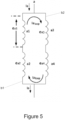
- Figure 5 schematically illustrates two parallel branches b1, b2 of a phase with respective two coils of the electrical machine of Figure 2 connected in series.
- coils a1 and a2 are connected in series with each other and coils a3 and a4 are connected in series with each other.
- the two parallel branches b1, b2 of Figure 5 may belong to a phase a of the electrical machine 1.
- This electrical machine 1 may comprise further phases which have not been illustrated for the sake of clarity.
- the electrical machine may comprise two further phases, and thus have three phases. In other examples, a different number of phases may be used.
- the electrical machine 1 may further comprise a sensor 12, 14 to sense a voltage over a single coil of the two coils connected in series and a controller 11 to measure the voltage through the sensor 12, 14 and determine a fault condition of the electrical machine 1 based at least on the measured voltage ea1, ea2, ea3, ea4 over time. Examples of methods for detecting a fault will be described later on.
- the senor 12, 14 may be any suitable sensing device able at least to sense a voltage signal or the like over a single coil of the electrical machine 1, such as e.g. a voltmeter.
- the number of sensors 12, 14 may vary depending on the case, for instance one or more coils of the electrical machine 1 may have such a sensor 12, 14 associated with them.
- a first sensor 12 is related to coil a1 and a second sensor 14 is related to coil a4.
- controller 11 may be a controlling device able at least to read and receive a voltage signal or the like through a sensing device such as sensor 12, 14.
- Controller 11 may comprise a processor and a memory; the memory may store instructions which comprise functionality to execute a method of detecting a fault condition according to any of the examples that are herein disclosed.
- the processor may execute instructions stored by the memory.
- Controller 11 may be associated and thus receive and/or process signals from one or more sensors 12, 14.
- controller 11 and sensor 12, 14 may be in data communication.
- This data communication may be, for instance, wired or wireless.
- the controller 11 and sensor 12, 14 may be integrally formed.
- the operation of measuring voltage may be alternatively performed over any of the coils, e.g. ea1, ea2, ea3 or ea4, even a plurality of single coils.
- a wired or wireless connection of the sensor 12, 14 and the controller 1 to the specific coil a1, a2, a3 or a4 may be adapted accordingly.
- the rotor 2 may comprise a plurality of magnets m1, m2, m3, m4 and the stator 3 may comprise a first pair of coils a1, a2 connected in series and a second pair of coils a3, a4 connected in series, wherein the second pair of coils a3, a4 may be arranged respectively at a different azimuthal position than the first pair of coils a1, a2, and may comprise a first sensor 12 associated with one of the coils a1, a2 of the first pair of coils, and a second sensor 14 associated with one of the coils a3, a4 of the second pair of coils a3, a4.
- each coil a1, a2, a3, a4 may be arranged at twelve, three, six and nine o'clock ( Figure 2 ).
- the azimuth angle between the first and second pairs of coils may be 180° in this example.
- the azimuth angle between the single coils may be 90°.
- the stator 3 may be ringshaped and comprise a plurality of teeth 31 wherein each tooth 31 is wound with a single coil.
- Figure 9 schematically illustrates a detail of stator teeth 31 of the electrical machine 1 of Figure 2 . The amount of coils may be adapted to particular needs and each of the coils is wound around its corresponding tooth 31 though in Figure 9 only coil a1 is illustrated.
- the stator is shown to be radially outside the rotor, but alternative arrangements e.g. the rotor radially outside the stator, and the rotor and stator axially facing each other are also possible.
- a wind turbine 160 comprises a tower 170 and a generator, wherein the generator may comprise a controller 11 for controlling the operation of the generator and a sensor 12, 14 for sensing a voltage over a single coil of two or more coils connected in series.
- the generator is an example of the electrical machine 1.
- the controller 11 may be configured to measure a voltage over the single coil through the sensor 12, 14 and determine a fault condition based at least on a measured voltage ea1, ea2, ea3, ea4 over time.
- controller 11 may be configured as a separate part from the generator so that the controller 11 may operate remotely.
- the controller 11 may be wired or wireless connected to the generator.
- the wind turbine 160 may further comprise a stator 3 having a plurality of coils a1, a2, a3, a4 and at least two of the coils are connected in series, wherein each coil a1, a2, a3, a4 may be wound around a tooth 31 of the stator 3.
- Figure 10 shows a flow diagram representing a method of fault detection 200 in an electrical machine 1 according to one example.
- the electrical machine 1 of the method of fault detection 200 may have a rotor 2 and a stator 3, one of the rotor 2 and stator 3 having at least two coils a1, a2, a3, a4 connected in series.
- the rotor 2, stator 3 and coils a1, a2, a3, a4 have been already described so further details about them will not be provided.
- the method of fault detection 200 comprises measuring 201 a voltage ea1, ea2, ea3, ea4 over a single coil of the two coils connected in series and determining 202 a fault condition based at least on the measured voltage ea1, ea2, ea3, ea4 over time.
- the single coil may be any of a1, a2, a3 or a4 and any coils of the phases of the electrical machine 1.
- a fault may be determined because the induced voltage ea1 on the single coil a1 (or any other single coil of the phase) may be directly affected.
- the voltage is sensed by the sensor 12, 14 and measured by the controller 11 through that sensor 12, 14.
- Controller 11 determines the fault condition based on the voltage over time.
- the fault condition may describe a negative fault condition or no fault condition, i.e. the electrical machine 1 works properly. Otherwise the fault condition may describe a fault condition of the electrical machine 1.
- Some examples of fault condition are set forth: According to one example of the method of fault detection 200, the fault condition may be related to a demagnetization of magnet m1, m2, m3, m4. Demagnetization may be total or at least partial.
- the fault condition may be related to a broken magnet.
- the fault condition may be related to a detached magnet, for instance from the rotor 2.
- Demagnetization and broken or detached magnet may be considered as some examples of magnet failures.
- the fault condition may be related to a relative eccentricity between the rotor 2 and the stator 3 of the electrical machine 1.
- Figure 3 schematically illustrates an eccentricity fault of the rotor 2 of the electrical machine 1 of Figure 2 .
- the rotor 2 may rotate about a rotating axis RR which is substantially concentric with respect to the stator 3.
- An electrical machine 1 without any substantial eccentricity would comprise a stator 3 whose central axis CS would match with the rotating axis RR of the rotor and therefore would have only one distance between facing surfaces of rotor and stator.
- the eccentricity of the rotor 2 may be defined with respect any portion of the stator 3, not only the position illustrated in Figure 3 .
- the fault condition may be related to an airgap deformation.
- Figure 4 schematically illustrates an airgap deformation fault of the electrical machine 1 of Figure 2 .
- airgap deformation may be caused by any deformation in at least one part of the rotor 2. That deformation may produce different airgaps g1, g2, g3 and g4 defined between different portions of rotor 2 and stator 3.
- g1 and g3 have substantially the same length while g2 and g4 have substantially the same length. This arrangement may vary and all the airgaps may differ from each other. Furthermore, the overall amount of airgaps may also vary.
- the method of fault detection 200 may comprise measuring the voltage ea1, ea2 over a single coil a1 or a2 of the first pair of coils and the voltage ea3, ea4 over a single coil a3 or a4 of the second pair of coils and mapping an airgap shape between the rotor 2 and the stator 3 based on measured voltages ea1, ea2, ea3, ea4.
- This example of the method may be implemented when the rotor 2 comprises a plurality of magnets m1, m2, m3, m4 and the stator 3 comprises a first pair of coils a1, a2 connected in series and a second pair of coils a3, a4 connected in series, wherein the second pair of coils a3, a4 may be arranged at a different azimuthal position with respect to the rotor 2 than the first pair of coils a1, a2.
- These positions may be predefined and may be distributed around the rotor 2 or the stator 3, this way an accurate mapping of the airgap shape may be produced.
- the method of fault detection 200 is implemented in an electrical machine 1 having at least two pairs of coils connected in series coils, for instance a1, a2 and a3, a4 where the second pair of coils a3, a4 connected in series is arranged at an azimuth angle of substantially 90° or 180° from the first pair of coils a1, a2.
- This feature can be seen for instance in Figure 2 and Figure 5 .
- the mapping of the airgap shape may be defined at twelve, three, six and nine o'clock positions (i.e. azimuth angles of 0°, 90°, 180, and 270°).
- the method of fault detection 200 may further comprise computing a local airgap value based on the measured voltage over time and based on at least one of a rotor speed and a magnet temperature.
- the method of fault detection 200 may further comprise computing a local airgap value based on the measured voltage over time and a rotor speed.
- the local airgap value may be computed based also on a magnet temperature.
- the airgap value may be computed by the controller 11.
- the measurement of voltage may vary if it is carried out at a predefined (nominal) magnet temperature or at a different magnet temperature, e.g. lower than the predefined one, because magnetic flux of a magnet may vary depending on the magnet temperature.
- An induced voltage in a coil is a derivative of a magnetic flux and magnetic flux may vary depending on, inter alia, the speed of the rotor.
- the measured voltage ea1 may comprise a waveform as illustrated in Figure 6.
- Figure 6 shows a chart of a voltage waveform over a single coil a1 of Figure 5 in a magnet fault case.
- the back-emf back electromotive force
- the method may further comprise, in some examples, performing a data processing on the waveform of the measured voltage over time.
- the data processing may be performed by the controller 11 based on the voltage data of the single coil measured through the sensor 12.
- the data processing may be exemplary based on a Fourier Transformation, for instance a Fast Fourier Transformation. That way a representation in the frequency domain may be produced.
- Figure 7 shows a chart of a decomposition from the voltage waveform of Figure 6 .
- any alternative algorithm may be implemented to discompose the waveform so as to convert the measured voltage ea1 (signal) from its original time domain to a representation in the frequency domain.
- the representation in the frequency domain obtained by any alternative algorithm may be the same as or similar to the one in Figure 7 .
- controller 11 may produce some values as represented in the chart of Figure 7 .
- the method of fault detection 200 may further comprise seeking sub-harmonics in a data-processed waveform of the measured voltage ea1. This action may be performed by the controller 11.
- the method of fault detection 200 may further comprise comparing sub-harmonics in the data-processed waveform and sub-harmonics of a reference waveform to determine a type of fault. The comparison may be performed by the controller 11.
- Some exemplary sub-harmonics of a reference waveform associated with exemplary faults may be stored in the memory of the controller 11.
- the controller may compare sub-harmonics in the data-processed waveform with such exemplary sub-harmonics so as to search any exact or at least partial match.
- the controller 11 may determine a type or types of fault which are associated to those sub-harmonics.
- the method of fault detection 200 may comprise, according to some examples, seeking an amplitude variation in the waveform of the measured voltage with respect to a reference voltage waveform.
- the measured voltage may comprise a waveform. This amplitude variation may be sought by the controller 11.
- the method may further comprise comparing amplitude variations in the waveform of the measured voltage ea1 and in the reference voltage waveform to determine a type of fault.
- the comparison may be performed by the controller 11.
- Memory of the controller 11 may store some reference voltage waveforms which are associated with specific fault types.
- the amplitude variation may be an amplitude reduction or an amplitude undulation, for example.
- Figure 6 is an example of an amplitude reduction. Such amplitude reduction may be detected by comparing at least one of each maximum and minimum of the measured voltage ea1 with at least one of the rest of maxima and minima of the voltage ea1. The controller 11 may search on data of the measured voltage looking for an amplitude reduction. When such reduction is found then the controller 11 may determine that the electrical machine does not work properly. In chart of Figure 6 an amplitude reduction is found approximately between 4 and 4.5 seconds.
- controller 11 may determine a magnet fault because the induced voltage ea1 on the single coil a1 (or any other single coil of the phase) is affected in a particular way since the demagnetized magnet is facing coil a1 when reduces amplitude of voltage.
- Figure 8 shows a voltage waveform over a single coil of Figure 5 which may occur in the case of an eccentricity.
- Figure 8 is an example of amplitude undulation, i.e. amplitude of chart line increases and decreases forming peaks and bottoms. If controller 11 detects an amplitude undulation as that one of Figure 8 it may determine an eccentricity fault condition as per Figure 3 , because when distance d2 is defined close to coil a3, induced voltage ea1 may be higher in coil a1.
- That method may be implemented in an example of electrical machine 1 which is of a three-phase type and comprises two parallel branches per phase, and each branch comprises two coils connected in series.
- the method may be carried out at each of the phases or at least one of the phases.
- the fault may be related to the rotor 2 of the electrical machine 1, i.e. a method of fault detection 200 in a rotor 2 of an electrical machine 1.
- the method may be also related to a magnet fault of the rotor 2, eccentricity of the rotor 2 with respect to the stator 3 or an airgap deformation as illustrated in Figure 4 .
- a degree of magnet failure (or specifically a degree of demagnetization) may be computed by the controller 11 and on the basis of the degree of magnet failure an output of the electrical machine 1 (e.g. generator) may be limited until the faulty magnet/s is repaired or replaced.
- a fatigue value in at least one faulty part of the electrical machine 1 may be calculated. If the fatigue value exceeds a reference fatigue value, an expected design lifetime of the faulty part may be reduced.
Landscapes
- Engineering & Computer Science (AREA)
- Power Engineering (AREA)
- Synchronous Machinery (AREA)
Description
- The present disclosure relates to methods of fault detection in an electrical machine and further relates to electrical machines. The disclosure also relates to wind turbines.
- Electrical machines, such as motors and generators, generally comprise a rotor structure and a stator structure. In case of permanent magnet excited generators (PMG), permanent magnets (PM) are generally arranged on the rotor (although they could also be arranged alternatively in the stator structure), whereas winding elements (e.g. coils) are usually provided on the stator (although they could alternatively be arranged in the rotor structure). In electrical machines, coils may be connected in series, in parallel or a combination of both, some coils connected in series in several parallel branches, see for example
US2011/0316464 A1 . - Permanent magnet generators are generally deemed to be reliable and require less maintenance than other generator typologies. Permanent magnet generators may be used for example in wind turbines, and also in offshore wind turbines. Wind turbines of this kind generally comprise a rotor with a rotor hub and a plurality of blades. The rotor is set into rotation under the influence of the wind on the blades. The rotation of the rotor shaft drives the rotor of the electrical machine as a generator either directly ("directly driven") or through the use of a gearbox.
- In electrical machines, particularly permanent magnet generators which can be used in wind turbines, there are several fault types that may occur. Examples of those faults are eccentricities of the rotor, airgap deformations between rotor and stator, and magnet faults such as demagnetization or broken/detached magnet(s).
- Fault diagnosis has an important role in a reliable operation of an electrical machine.
- Airgap deformation and eccentricities may cause a higher structural stress and mechanical problems which can be potentially catastrophic faults with increased operational costs.
- A detached or broken magnet may cause a loss of electromagnetic force.
- Moreover, a detached or broken magnet may cause a loss of parts to the airgap between rotor and stator and thus severe mechanical problems may occur.
- In the case of permanent magnet generators, demagnetization may occur because of a stator short-circuit or an improper connection of a coil (among others), if a demagnetized pole is not detected (and not replaced), current in the stator may increase to compensate reduced back-emf (back electromotive force), which can lead to higher losses and higher temperatures. Performance of the generator can thus be reduced.
- Eccentricity of the rotor and airgap deformation faults are usually measured by airgap sensors placed on a stator tooth and a rotor pole. However, those sensors require more complex integration in the electrical machine, since they need to be directly placed in the airgap, see for example "2-Pole turbo-generator eccentricity diagnosis by split-phase current signature analysis", C. Bruzzese, 2013 9th IEEE International Symposium on Diagnostics for Electric Machines, Power Electronics and Drives (SDEMPED),XP032514154.
- In the existing solutions, magnet faults may be indirectly detected by current or phase voltage monitoring. The increased current to compensate reduced back-emf requires using a complex signal processing to detect a magnet fault.
- Furthermore, this current or phase voltage monitoring solution may not detect incipient faults, since stator (or rotor) currents and voltage signals are not directly affected by the magnet fault.
- The present disclosure provides examples of methods and devices that at least partially resolve some of the aforementioned disadvantages.
- The present invention is defined by a method of fault detection according to
claim 1 and a wind turbine according toclaim 14. - In a first aspect, a method of fault detection in an electrical machine is provided. The electrical machine has a rotor and a stator, one of the rotor and stator having at least two coils connected in series. The method comprises measuring a voltage over a single coil of the two coils connected in series. The method further comprises determining a fault condition based at least on the measured voltage over time.
- In this aspect, a method with an enhanced sensitivity to fault detection is obtained with respect to the known solutions since voltage of a single coil is directly affected by the faults, rather than an indirect measurement of total phase current or total phase voltage. The single coil voltage in coils connected in series is less sensitive to circulating currents in the coils which compensate reduced back-emf.
- Furthermore, using a single coil voltage measurement instead of indirectly current or phase voltage monitoring requires a simpler signal processing than previous solutions.
- The enhanced sensitivity also allows for incipient fault detection (magnet fault, eccentricity, airgap deformation, etc.), which can avoid potential catastrophic faults and thus the operational cost.
- Thanks to this aspect, airgap sensors with complex integration in the electrical machine are not needed to determine an airgap deformation fault.
- Non-limiting examples of the present disclosure will be described in the following, with reference to the appended drawings, in which:
-
Figure 1 illustrates a perspective view of a wind turbine according to one example; -
Figure 2 schematically represents a rotor and a stator of an electrical machine according to one example; -
Figure 3 schematically illustrates an eccentricity fault of the rotor of the electrical machine ofFigure 2 ; -
Figure 4 schematically illustrates an airgap deformation fault of the electrical machine ofFigure 2 ; -
Figure 5 schematically illustrates two parallel branches with two coils connected in series of the electrical machine ofFigure 2 ; -
Figure 6 shows a chart of a voltage waveform over a single coil ofFigure 5 in a magnet fault case; -
Figure 7 shows a chart of a decomposition from the voltage waveform ofFigure 6 ; -
Figure 8 shows a voltage waveform over a single coil ofFigure 5 in an eccentricity fault case; -
Figure 9 schematically illustrates a detail of stator teeth of the electrical machine ofFigure 2 ; -
Figure 10 shows a flow diagram representing a method of fault detection in an electrical machine according to one example. - In these figures the same reference signs have been used to designate matching elements. Some parts have not been illustrated for the sake of clarity.
-
Figure 1 illustrates a perspective view of one example of awind turbine 160. As shown, thewind turbine 160 includes atower 170 extending from asupport surface 150, anacelle 161 mounted on thetower 170, and arotor 115 coupled to thenacelle 161. Therotor 115 includes arotatable hub 110 and at least onerotor blade 120 coupled to and extending outwardly from thehub 110. For example, in the illustrated embodiment, therotor 115 includes threerotor blades 120. However, in an alternative embodiment, therotor 115 may include more or less than threerotor blades 120. Eachrotor blade 120 may be spaced about thehub 110 to facilitate rotating therotor 115 to enable kinetic energy to be transferred from the wind into usable mechanical energy, and subsequently, electrical energy. For instance, thehub 110 may be rotatably coupled to an electric generator. This electric generator is an example ofelectrical machine 1, as illustrated inFigure 2 , positioned within thenacelle 161 to permit electrical energy to be produced. -
Figure 2 schematically represents arotor 2 and astator 3 of anelectrical machine 1 according to one example. Thiselectrical machine 1 may be a direct drive wind turbine generator which may be disposed within thenacelle 161. - The
electrical machine 1 comprises therotor 2 and thestator 3 and therotor 2 may comprise a plurality of magnets m1, m2, m3, m4. In rotation, the plurality of magnets are arranged to consecutively face coils a1, a2, a3, a4 of thestator 3 when the rotor is driven. In the case of a wind turbine generator, the rotor is set into rotation by rotation of the rotor (which in turn is rotated under the action of the wind) so as to generate electrical energy. - Alternatively, coils may be arranged in the
rotor 2 and magnets in thestator 3. In this example, the magnets m1, m2, m3, m4 are permanent magnets. In alternative examples, the electrical machine may be a motor. - One of the
rotor 2 andstator 3 comprises two coils connected in series. This can be seen inFigure 5 which schematically illustrates two parallel branches b1, b2 of a phase with respective two coils of the electrical machine ofFigure 2 connected in series. As shown inFigure 5 , coils a1 and a2 are connected in series with each other and coils a3 and a4 are connected in series with each other. The two parallel branches b1, b2 ofFigure 5 may belong to a phase a of theelectrical machine 1. Thiselectrical machine 1 may comprise further phases which have not been illustrated for the sake of clarity. In one particular example, the electrical machine may comprise two further phases, and thus have three phases. In other examples, a different number of phases may be used. - According to one example illustrated in
Figure 2 , theelectrical machine 1 may further comprise asensor controller 11 to measure the voltage through thesensor electrical machine 1 based at least on the measured voltage ea1, ea2, ea3, ea4 over time. Examples of methods for detecting a fault will be described later on. - In some examples, the
sensor electrical machine 1, such as e.g. a voltmeter. The number ofsensors electrical machine 1 may have such asensor Figure 2 afirst sensor 12 is related to coil a1 and asecond sensor 14 is related to coil a4. - In further examples, the
controller 11 may be a controlling device able at least to read and receive a voltage signal or the like through a sensing device such assensor -
Controller 11 may comprise a processor and a memory; the memory may store instructions which comprise functionality to execute a method of detecting a fault condition according to any of the examples that are herein disclosed. The processor may execute instructions stored by the memory. -
Controller 11 may be associated and thus receive and/or process signals from one ormore sensors - In some examples,
controller 11 andsensor - This data communication may be, for instance, wired or wireless. In still further examples, the
controller 11 andsensor - Although the measured voltage ea1 belongs to coil a1 and voltage ea4 belongs to coil a4 according to
Figures 2 and5 , the operation of measuring voltage may be alternatively performed over any of the coils, e.g. ea1, ea2, ea3 or ea4, even a plurality of single coils. A wired or wireless connection of thesensor controller 1 to the specific coil a1, a2, a3 or a4 may be adapted accordingly. - In
Figure 5 , a phase current has been indicated as la and circulating currents in the parallel branches b1, b2 have been indicated as laloop. - In one example of the
electrical machine 1 as perFigure 2 , therotor 2 may comprise a plurality of magnets m1, m2, m3, m4 and thestator 3 may comprise a first pair of coils a1, a2 connected in series and a second pair of coils a3, a4 connected in series, wherein the second pair of coils a3, a4 may be arranged respectively at a different azimuthal position than the first pair of coils a1, a2, and may comprise afirst sensor 12 associated with one of the coils a1, a2 of the first pair of coils, and asecond sensor 14 associated with one of the coils a3, a4 of the second pair of coils a3, a4. For instance, each coil a1, a2, a3, a4 may be arranged at twelve, three, six and nine o'clock (Figure 2 ). In other words, the azimuth angle between the first and second pairs of coils may be 180° in this example. In this example also, the azimuth angle between the single coils may be 90°. By measuring voltages at e.g. 90° or 180° angles difference, an overview of the performance of the rotor and/or stator or an overview of the airgap around the perimeter of the electrical machine may be obtained. - According to some examples of the
electrical machine 1, thestator 3 may be ringshaped and comprise a plurality ofteeth 31 wherein eachtooth 31 is wound with a single coil.Figure 9 schematically illustrates a detail ofstator teeth 31 of theelectrical machine 1 ofFigure 2 . The amount of coils may be adapted to particular needs and each of the coils is wound around its correspondingtooth 31 though inFigure 9 only coil a1 is illustrated. Although in this example, the stator is shown to be radially outside the rotor, but alternative arrangements e.g. the rotor radially outside the stator, and the rotor and stator axially facing each other are also possible. - According to an aspect, a
wind turbine 160 comprises atower 170 and a generator, wherein the generator may comprise acontroller 11 for controlling the operation of the generator and asensor electrical machine 1. Thecontroller 11 may be configured to measure a voltage over the single coil through thesensor - Alternatively, the
controller 11 may be configured as a separate part from the generator so that thecontroller 11 may operate remotely. Thecontroller 11 may be wired or wireless connected to the generator. - In some examples, the
wind turbine 160 may further comprise astator 3 having a plurality of coils a1, a2, a3, a4 and at least two of the coils are connected in series, wherein each coil a1, a2, a3, a4 may be wound around atooth 31 of thestator 3. - In the following, examples of operation of the above described
electrical machines 1 will be provided related to examples of methods offault detection 200. -
Figure 10 shows a flow diagram representing a method offault detection 200 in anelectrical machine 1 according to one example. - The
electrical machine 1 of the method offault detection 200 may have arotor 2 and astator 3, one of therotor 2 andstator 3 having at least two coils a1, a2, a3, a4 connected in series. Therotor 2,stator 3 and coils a1, a2, a3, a4 have been already described so further details about them will not be provided. - According to an aspect, the method of
fault detection 200 according toFigure 10 comprises measuring 201 a voltage ea1, ea2, ea3, ea4 over a single coil of the two coils connected in series and determining 202 a fault condition based at least on the measured voltage ea1, ea2, ea3, ea4 over time. As mentioned above, the single coil may be any of a1, a2, a3 or a4 and any coils of the phases of theelectrical machine 1. By this exemplary method offault detection 200, a fault may be determined because the induced voltage ea1 on the single coil a1 (or any other single coil of the phase) may be directly affected. - According to this aspect, the voltage is sensed by the
sensor controller 11 through thatsensor Controller 11 determines the fault condition based on the voltage over time. The fault condition may describe a negative fault condition or no fault condition, i.e. theelectrical machine 1 works properly. Otherwise the fault condition may describe a fault condition of theelectrical machine 1. Some examples of fault condition are set forth:
According to one example of the method offault detection 200, the fault condition may be related to a demagnetization of magnet m1, m2, m3, m4. Demagnetization may be total or at least partial. - According to a further example of the method of
fault detection 200, the fault condition may be related to a broken magnet. Alternatively, the fault condition may be related to a detached magnet, for instance from therotor 2. - Demagnetization and broken or detached magnet may be considered as some examples of magnet failures.
- According to another example of the method of
fault detection 200, the fault condition may be related to a relative eccentricity between therotor 2 and thestator 3 of theelectrical machine 1.Figure 3 schematically illustrates an eccentricity fault of therotor 2 of theelectrical machine 1 ofFigure 2 . In operating condition, therotor 2 may rotate about a rotating axis RR which is substantially concentric with respect to thestator 3. - In
Figure 3 different distances d1 and d2 have been referenced between surfaces of therotor 2 and thestator 3 that face each other. Such difference can be due to incorrect placements of the rotating axis of the rotor RR and the central axis of the stator CS, i.e. rotating axis of the rotor RR and central axis of the stator do not coincide. This way, inFigure 3 d1 is shorter than d2 but d2 may be shorter than d1, particularly when therotor 2 turns 180° about its rotating axis RR. - An
electrical machine 1 without any substantial eccentricity would comprise astator 3 whose central axis CS would match with the rotating axis RR of the rotor and therefore would have only one distance between facing surfaces of rotor and stator. - The eccentricity of the
rotor 2 may be defined with respect any portion of thestator 3, not only the position illustrated inFigure 3 . - According to still another example of the method of
fault detection 200, the fault condition may be related to an airgap deformation.Figure 4 schematically illustrates an airgap deformation fault of theelectrical machine 1 ofFigure 2 . - More particularly, that airgap deformation may be caused by any deformation in at least one part of the
rotor 2. That deformation may produce different airgaps g1, g2, g3 and g4 defined between different portions ofrotor 2 andstator 3. InFigure 4 , g1 and g3 have substantially the same length while g2 and g4 have substantially the same length. This arrangement may vary and all the airgaps may differ from each other. Furthermore, the overall amount of airgaps may also vary. - The method of
fault detection 200 according to some examples may comprise measuring the voltage ea1, ea2 over a single coil a1 or a2 of the first pair of coils and the voltage ea3, ea4 over a single coil a3 or a4 of the second pair of coils and mapping an airgap shape between therotor 2 and thestator 3 based on measured voltages ea1, ea2, ea3, ea4. This example of the method may be implemented when therotor 2 comprises a plurality of magnets m1, m2, m3, m4 and thestator 3 comprises a first pair of coils a1, a2 connected in series and a second pair of coils a3, a4 connected in series, wherein the second pair of coils a3, a4 may be arranged at a different azimuthal position with respect to therotor 2 than the first pair of coils a1, a2. These positions may be predefined and may be distributed around therotor 2 or thestator 3, this way an accurate mapping of the airgap shape may be produced. - In some examples, the method of
fault detection 200 is implemented in anelectrical machine 1 having at least two pairs of coils connected in series coils, for instance a1, a2 and a3, a4 where the second pair of coils a3, a4 connected in series is arranged at an azimuth angle of substantially 90° or 180° from the first pair of coils a1, a2. This feature can be seen for instance inFigure 2 andFigure 5 . With such arrangement, the mapping of the airgap shape may be defined at twelve, three, six and nine o'clock positions (i.e. azimuth angles of 0°, 90°, 180, and 270°). - In one example when the
electrical machine 1 comprises a plurality of magnets m1, m2, m3, m4, the method offault detection 200 may further comprise computing a local airgap value based on the measured voltage over time and based on at least one of a rotor speed and a magnet temperature. - In some other examples when the
electrical machine 1 comprises a plurality of magnets m1, m2, m3, m4, the method offault detection 200 may further comprise computing a local airgap value based on the measured voltage over time and a rotor speed. The local airgap value may be computed based also on a magnet temperature. - The airgap value may be computed by the
controller 11. - The measurement of voltage may vary if it is carried out at a predefined (nominal) magnet temperature or at a different magnet temperature, e.g. lower than the predefined one, because magnetic flux of a magnet may vary depending on the magnet temperature.
- An induced voltage in a coil is a derivative of a magnetic flux and magnetic flux may vary depending on, inter alia, the speed of the rotor.
- Therefore, by taking into account the measured voltage over time and at least one of the magnet temperature and the rotor speed an accurate calculation of an airgap value may be achieved. By taking into account the measured voltage, the magnet temperature and the rotor speed the calculation of an airgap value may be even more accurate.
- The measured voltage ea1 may comprise a waveform as illustrated in
Figure 6. Figure 6 shows a chart of a voltage waveform over a single coil a1 ofFigure 5 in a magnet fault case. InFigure 6 the back-emf (back electromotive force) is represented as a function over time. - In order to determine the fault condition of the
electrical machine 1, some alternative approaches may be implemented in the controller. - According to one approach, the method may further comprise, in some examples, performing a data processing on the waveform of the measured voltage over time. The data processing may be performed by the
controller 11 based on the voltage data of the single coil measured through thesensor 12. - The data processing may be exemplary based on a Fourier Transformation, for instance a Fast Fourier Transformation. That way a representation in the frequency domain may be produced.
Figure 7 shows a chart of a decomposition from the voltage waveform ofFigure 6 . - Alternatively, other algorithms may be implemented to discompose the waveform so as to convert the measured voltage ea1 (signal) from its original time domain to a representation in the frequency domain. The representation in the frequency domain obtained by any alternative algorithm may be the same as or similar to the one in
Figure 7 . - If the
controller 11 carries out a data processing it may produce some values as represented in the chart ofFigure 7 . - In an example, the method of
fault detection 200 may further comprise seeking sub-harmonics in a data-processed waveform of the measured voltage ea1. This action may be performed by thecontroller 11. - In a yet further example, the method of
fault detection 200 may further comprise comparing sub-harmonics in the data-processed waveform and sub-harmonics of a reference waveform to determine a type of fault. The comparison may be performed by thecontroller 11. - Some exemplary sub-harmonics of a reference waveform associated with exemplary faults may be stored in the memory of the
controller 11. The controller may compare sub-harmonics in the data-processed waveform with such exemplary sub-harmonics so as to search any exact or at least partial match. In case of an exact or at least partial match, thecontroller 11 may determine a type or types of fault which are associated to those sub-harmonics. - According to another approach to determine the fault condition, the method of
fault detection 200 may comprise, according to some examples, seeking an amplitude variation in the waveform of the measured voltage with respect to a reference voltage waveform. As above mentioned, the measured voltage may comprise a waveform. This amplitude variation may be sought by thecontroller 11. - In some examples, the method may further comprise comparing amplitude variations in the waveform of the measured voltage ea1 and in the reference voltage waveform to determine a type of fault. The comparison may be performed by the
controller 11. Memory of thecontroller 11 may store some reference voltage waveforms which are associated with specific fault types. - The amplitude variation may be an amplitude reduction or an amplitude undulation, for example.
-
Figure 6 is an example of an amplitude reduction. Such amplitude reduction may be detected by comparing at least one of each maximum and minimum of the measured voltage ea1 with at least one of the rest of maxima and minima of the voltage ea1. Thecontroller 11 may search on data of the measured voltage looking for an amplitude reduction. When such reduction is found then thecontroller 11 may determine that the electrical machine does not work properly. In chart ofFigure 6 an amplitude reduction is found approximately between 4 and 4.5 seconds. - By way of example, if
controller 11 detects an amplitude reduction as that one ofFigure 6 it may determine a magnet fault because the induced voltage ea1 on the single coil a1 (or any other single coil of the phase) is affected in a particular way since the demagnetized magnet is facing coil a1 when reduces amplitude of voltage. -
Figure 8 shows a voltage waveform over a single coil ofFigure 5 which may occur in the case of an eccentricity.Figure 8 is an example of amplitude undulation, i.e. amplitude of chart line increases and decreases forming peaks and bottoms. Ifcontroller 11 detects an amplitude undulation as that one ofFigure 8 it may determine an eccentricity fault condition as perFigure 3 , because when distance d2 is defined close to coil a3, induced voltage ea1 may be higher in coil a1. - According to an example of the method of
fault detection 200, that method may be implemented in an example ofelectrical machine 1 which is of a three-phase type and comprises two parallel branches per phase, and each branch comprises two coils connected in series. The method may be carried out at each of the phases or at least one of the phases. - In some examples of the method of
fault detection 200 the fault may be related to therotor 2 of theelectrical machine 1, i.e. a method offault detection 200 in arotor 2 of anelectrical machine 1. For instance, the method may be also related to a magnet fault of therotor 2, eccentricity of therotor 2 with respect to thestator 3 or an airgap deformation as illustrated inFigure 4 . - When a fault condition related to a magnet failure such as a demagnetization of a magnet m1, m2, m3, m4 is determined following the method of
fault detection 200, a degree of magnet failure (or specifically a degree of demagnetization) may be computed by thecontroller 11 and on the basis of the degree of magnet failure an output of the electrical machine 1 (e.g. generator) may be limited until the faulty magnet/s is repaired or replaced. - When a fault condition related to a relative eccentricity between the
rotor 2 and thestator 3 of theelectrical machine 1 or related to an airgap deformation is determined following the method offault detection 200, a fatigue value in at least one faulty part of theelectrical machine 1 may be calculated. If the fatigue value exceeds a reference fatigue value, an expected design lifetime of the faulty part may be reduced. - This written description uses examples to disclose the invention, including the preferred embodiments, and also to enable any person skilled in the art to practice the invention, including making and using any devices or systems and performing any incorporated methods. The patentable scope of the invention is defined by the claims, and may include other examples that occur to those skilled in the art.
- Aspects from the various embodiments described, as well as other known equivalents for each such aspects, can be mixed and matched by one of ordinary skill in the art to construct additional embodiments and techniques in accordance with principles of this application. If reference signs related to drawings are placed in parentheses in a claim, they are solely for attempting to increase the intelligibility of the claim, and shall not be construed as limiting the scope of the claim.
Claims (15)
- A method of fault detection (200) in an electrical machine (1) having a rotor (2) and a stator (3), wherein the stator is radially outside or inside the rotor,
wherein the rotor (2) comprises a plurality of magnets (m1, m2, m3, m4) and the stator (3) comprises a phase with a first branch and a second branch arranged in parallel with the first branch, including a first pair of coils (a1, a2) connected in series in the first branch, and a second pair of coils (a3, a4) connected in series in the second branch, the method comprising:measuring (201) a voltage over a single coil of one of the pairs of coils connected in series;determining (202) a fault condition based at least on the measured voltage (ea1, ea2, ea3, ea4) over time. - The method (200) according to claim 1, wherein the fault condition is related to a demagnetization of a magnet (m1, m2, m3, m4).
- The method (200) according to any of claims 1 - 2, wherein the fault condition is related to a broken magnet (m1, m2, m3, m4).
- The method (200) according to any of claims 1 - 3, wherein the fault condition is related to a relative eccentricity between the rotor (2) and the stator (3) of the electrical machine (1).
- The method (200) according to any of claims 1 - 4, wherein the fault condition is related to an airgap deformation.
- The method (200) according to claim 5, wherein the second pair of coils (a3, a4) is arranged at a different azimuthal position with respect to the rotor (2) than the first pair of coils (a1, a2), the method comprising:measuring the voltage over a single coil of the first pair of coils (a1, a2) and over a single coil of the second pair of coils (a3, a4);mapping an airgap shape between the rotor (2) and the stator (3) based on the measured voltages (ea1, ea2, ea3, ea4).
- The method (200) according to claim 5, , the method further comprises:
computing a local airgap value based on the measured voltage (ea1, ea2, ea3, ea4) over time and based on at least one of a rotor speed and a magnet temperature. - The method (200) according to any of claims 1 - 7, wherein the measured voltage (ea1, ea2, ea3, ea4) comprises a waveform and the method further comprises:
performing a data processing on the waveform of the measured voltage (ea1, ea2, ea3, ea4) over time. - The method (200) according to claim 8, wherein the method further comprises:
seeking sub-harmonics in a data-processed waveform of the measured voltage (ea1, ea2, ea3, ea4). - The method (200) according to claim 9, wherein the method further comprises:
comparing sub-harmonics on the data-processed waveform and reference sub-harmonics to determine a type of fault. - The method (200) according to any of claims 1 - 7, wherein the measured voltage comprises a waveform and the method further comprises:
seeking an amplitude variation in a waveform of the measured voltage (ea1, ea2, ea3, ea4) with respect to a reference voltage waveform. - The method (200) according to claim 11, wherein the method further comprises:
comparing amplitude variations in the measured voltage (ea1, ea2, ea3, ea4) and amplitude variations in the reference voltage waveform to determine a type of fault. - The method (200) according to any of claims 1 - 12, wherein the fault of the electrical machine (1) is related to the rotor (2) of the electrical machine (1).
- A wind turbine (160) comprising a tower (170) and a generator,the generator having a rotor (2) and a stator (3), wherein the stator is radially outside or inside the rotor,wherein the rotor (2) comprises a plurality of magnets (m1, m2, m3, m4) and the stator (3) comprises a phase with a first and a second branch arranged in parallel with the first branch, including a first pair of coils (a1, a2) connected in series in the first branch, and a second pair of coils (a3, a4) connected in series in the second branch,and wherein the generator further comprises a controller (11) for controlling the operation of the generator and a sensor (12, 14) for sensing a voltage over a single coil of two or more coils (a1, a2, a3, a4) connected in series, wherein the controller (11) is configured to carry out a method of fault detection according to any of claims 1 - 11.
- The wind turbine (160) according to claim 14, wherein each coil (a1, a2, a3, a4) is wound around a single tooth (31) of the stator (3).
Priority Applications (2)
| Application Number | Priority Date | Filing Date | Title |
|---|---|---|---|
| ES18382035T ES2946009T3 (en) | 2018-01-23 | 2018-01-23 | Fault detection procedures in an electrical machine, electrical machines and wind turbines |
| EP18382035.6A EP3514945B1 (en) | 2018-01-23 | 2018-01-23 | Methods of fault detection in an electrical machine, electrical machines and wind turbines |
Applications Claiming Priority (1)
| Application Number | Priority Date | Filing Date | Title |
|---|---|---|---|
| EP18382035.6A EP3514945B1 (en) | 2018-01-23 | 2018-01-23 | Methods of fault detection in an electrical machine, electrical machines and wind turbines |
Publications (2)
| Publication Number | Publication Date |
|---|---|
| EP3514945A1 EP3514945A1 (en) | 2019-07-24 |
| EP3514945B1 true EP3514945B1 (en) | 2023-03-01 |
Family
ID=61168025
Family Applications (1)
| Application Number | Title | Priority Date | Filing Date |
|---|---|---|---|
| EP18382035.6A Active EP3514945B1 (en) | 2018-01-23 | 2018-01-23 | Methods of fault detection in an electrical machine, electrical machines and wind turbines |
Country Status (2)
| Country | Link |
|---|---|
| EP (1) | EP3514945B1 (en) |
| ES (1) | ES2946009T3 (en) |
Families Citing this family (3)
| Publication number | Priority date | Publication date | Assignee | Title |
|---|---|---|---|---|
| CN110492689B (en) * | 2019-08-28 | 2022-05-20 | 河海大学 | Permanent magnet motor structure and method capable of detecting demagnetization of permanent magnet and eccentric rotor fault |
| CN113922540B (en) * | 2021-10-12 | 2022-12-09 | 珠海格力电器股份有限公司 | Motor, control method and device thereof and vehicle |
| CN117269754B (en) * | 2023-08-17 | 2024-06-21 | 贵州大学 | IPSM rotor demagnetizing and eccentric fault diagnosis method based on convolutional neural network operation |
Family Cites Families (2)
| Publication number | Priority date | Publication date | Assignee | Title |
|---|---|---|---|---|
| FR2961975B1 (en) * | 2010-06-25 | 2012-07-20 | Valeo Systemes De Controle Moteur | ELECTRICAL DEVICE COMPRISING AN ALTERNATING CURRENT ELECTRIC MOTOR AND A CONTROL INVERTER AND A METHOD FOR MEASURING THE ELECTROMOTIVE FORCE OF THIS DEVICE |
| EP2704297B1 (en) * | 2012-08-28 | 2020-02-19 | GE Energy Power Conversion Technology Ltd | DC electrical machines |
-
2018
- 2018-01-23 ES ES18382035T patent/ES2946009T3/en active Active
- 2018-01-23 EP EP18382035.6A patent/EP3514945B1/en active Active
Also Published As
| Publication number | Publication date |
|---|---|
| EP3514945A1 (en) | 2019-07-24 |
| ES2946009T3 (en) | 2023-07-11 |
Similar Documents
| Publication | Publication Date | Title |
|---|---|---|
| RU2449454C2 (en) | Method and device process control of rotating machines | |
| Nandi et al. | Fault diagnosis of electrical machines-a review | |
| Shah et al. | Stator-interturn-fault detection of doubly fed induction generators using rotor-current and search-coil-voltage signature analysis | |
| CN104155567B (en) | Positioning method of turn-to-turn short circuit fault of doubly-fed generator rotor | |
| EP3514945B1 (en) | Methods of fault detection in an electrical machine, electrical machines and wind turbines | |
| EP3480610B1 (en) | Diagnosing a winding set of a stator | |
| CN109541461B (en) | Permanent magnet synchronous motor eccentric fault diagnosis method based on magnetic field distribution monitoring | |
| CN109039176B (en) | A kind of permanent magnet synchronous motor rotation becomes the detection device and detection method of zero-bit initial angle | |
| WO2009048970A1 (en) | Power angle monitor | |
| US20150035520A1 (en) | Calibration and monitoring of an angle measuring system for electrical machines | |
| US20130168960A1 (en) | Method and apparatus for pole-slip detection in synchronous generators | |
| EP3220120B1 (en) | Method, diagnostic device and system for determining fault conditions in an electrical machine | |
| WO2013136098A1 (en) | Method for rotor winding damage detection in rotating alternating machines by differential measurement of magnetic field by using two measuring coils | |
| WO2014031895A2 (en) | Systems and methods for rotor angle measurement in an electrical generator | |
| EP2592728B1 (en) | Electromagnetic device | |
| CN109738796A (en) | Nuclear power Half Speed steam turbine generator excitation winding trouble-shooter and diagnostic method | |
| Balasubramanian et al. | Model based fault detection and diagnosis of doubly fed induction generators–a review | |
| Im et al. | Static and dynamic eccentricity faults diagnosis in PM synchronous motor using planar search coil | |
| US7323843B2 (en) | Method and device for treating signals for detection of stator and rotor errors in magnetic circuits in a synchronous machine | |
| EP3301792B1 (en) | Method and measurement system for analyzing a temporal variation of a magnetic flux produced by a magnetic field producer at a rotor of a generator | |
| Wehner et al. | Search coil systems for early fault detection in wind turbine generators | |
| CN111983419A (en) | Method and system for detecting a multiphase brushless exciter rectifier diode fault | |
| CN113777530B (en) | Open-circuit fault diagnosis method for rotating diode of inner rotor type three-phase brushless exciter | |
| HUANG et al. | Online rotor fault diagnosis of permanent magnet synchronous motors based on stator tooth flux | |
| KR102071275B1 (en) | Voltage phase-detecting apparatus for generators using rpm signal |
Legal Events
| Date | Code | Title | Description |
|---|---|---|---|
| PUAI | Public reference made under article 153(3) epc to a published international application that has entered the european phase |
Free format text: ORIGINAL CODE: 0009012 |
|
| STAA | Information on the status of an ep patent application or granted ep patent |
Free format text: STATUS: THE APPLICATION HAS BEEN PUBLISHED |
|
| AK | Designated contracting states |
Kind code of ref document: A1 Designated state(s): AL AT BE BG CH CY CZ DE DK EE ES FI FR GB GR HR HU IE IS IT LI LT LU LV MC MK MT NL NO PL PT RO RS SE SI SK SM TR |
|
| AX | Request for extension of the european patent |
Extension state: BA ME |
|
| STAA | Information on the status of an ep patent application or granted ep patent |
Free format text: STATUS: REQUEST FOR EXAMINATION WAS MADE |
|
| 17P | Request for examination filed |
Effective date: 20200124 |
|
| RBV | Designated contracting states (corrected) |
Designated state(s): AL AT BE BG CH CY CZ DE DK EE ES FI FR GB GR HR HU IE IS IT LI LT LU LV MC MK MT NL NO PL PT RO RS SE SI SK SM TR |
|
| STAA | Information on the status of an ep patent application or granted ep patent |
Free format text: STATUS: EXAMINATION IS IN PROGRESS |
|
| 17Q | First examination report despatched |
Effective date: 20210430 |
|
| STAA | Information on the status of an ep patent application or granted ep patent |
Free format text: STATUS: EXAMINATION IS IN PROGRESS |
|
| GRAP | Despatch of communication of intention to grant a patent |
Free format text: ORIGINAL CODE: EPIDOSNIGR1 |
|
| STAA | Information on the status of an ep patent application or granted ep patent |
Free format text: STATUS: GRANT OF PATENT IS INTENDED |
|
| INTG | Intention to grant announced |
Effective date: 20220929 |
|
| GRAS | Grant fee paid |
Free format text: ORIGINAL CODE: EPIDOSNIGR3 |
|
| GRAA | (expected) grant |
Free format text: ORIGINAL CODE: 0009210 |
|
| STAA | Information on the status of an ep patent application or granted ep patent |
Free format text: STATUS: THE PATENT HAS BEEN GRANTED |
|
| AK | Designated contracting states |
Kind code of ref document: B1 Designated state(s): AL AT BE BG CH CY CZ DE DK EE ES FI FR GB GR HR HU IE IS IT LI LT LU LV MC MK MT NL NO PL PT RO RS SE SI SK SM TR |
|
| REG | Reference to a national code |
Ref country code: GB Ref legal event code: FG4D |
|
| REG | Reference to a national code |
Ref country code: CH Ref legal event code: EP Ref country code: AT Ref legal event code: REF Ref document number: 1551705 Country of ref document: AT Kind code of ref document: T Effective date: 20230315 |
|
| REG | Reference to a national code |
Ref country code: DE Ref legal event code: R096 Ref document number: 602018046628 Country of ref document: DE |
|
| REG | Reference to a national code |
Ref country code: IE Ref legal event code: FG4D |
|
| REG | Reference to a national code |
Ref country code: NL Ref legal event code: FP |
|
| REG | Reference to a national code |
Ref country code: LT Ref legal event code: MG9D |
|
| REG | Reference to a national code |
Ref country code: ES Ref legal event code: FG2A Ref document number: 2946009 Country of ref document: ES Kind code of ref document: T3 Effective date: 20230711 |
|
| P01 | Opt-out of the competence of the unified patent court (upc) registered |
Effective date: 20230529 |
|
| PG25 | Lapsed in a contracting state [announced via postgrant information from national office to epo] |
Ref country code: RS Free format text: LAPSE BECAUSE OF FAILURE TO SUBMIT A TRANSLATION OF THE DESCRIPTION OR TO PAY THE FEE WITHIN THE PRESCRIBED TIME-LIMIT Effective date: 20230301 Ref country code: NO Free format text: LAPSE BECAUSE OF FAILURE TO SUBMIT A TRANSLATION OF THE DESCRIPTION OR TO PAY THE FEE WITHIN THE PRESCRIBED TIME-LIMIT Effective date: 20230601 Ref country code: LV Free format text: LAPSE BECAUSE OF FAILURE TO SUBMIT A TRANSLATION OF THE DESCRIPTION OR TO PAY THE FEE WITHIN THE PRESCRIBED TIME-LIMIT Effective date: 20230301 Ref country code: LT Free format text: LAPSE BECAUSE OF FAILURE TO SUBMIT A TRANSLATION OF THE DESCRIPTION OR TO PAY THE FEE WITHIN THE PRESCRIBED TIME-LIMIT Effective date: 20230301 Ref country code: HR Free format text: LAPSE BECAUSE OF FAILURE TO SUBMIT A TRANSLATION OF THE DESCRIPTION OR TO PAY THE FEE WITHIN THE PRESCRIBED TIME-LIMIT Effective date: 20230301 |
|
| REG | Reference to a national code |
Ref country code: AT Ref legal event code: MK05 Ref document number: 1551705 Country of ref document: AT Kind code of ref document: T Effective date: 20230301 |
|
| PG25 | Lapsed in a contracting state [announced via postgrant information from national office to epo] |
Ref country code: SE Free format text: LAPSE BECAUSE OF FAILURE TO SUBMIT A TRANSLATION OF THE DESCRIPTION OR TO PAY THE FEE WITHIN THE PRESCRIBED TIME-LIMIT Effective date: 20230301 Ref country code: PL Free format text: LAPSE BECAUSE OF FAILURE TO SUBMIT A TRANSLATION OF THE DESCRIPTION OR TO PAY THE FEE WITHIN THE PRESCRIBED TIME-LIMIT Effective date: 20230301 Ref country code: GR Free format text: LAPSE BECAUSE OF FAILURE TO SUBMIT A TRANSLATION OF THE DESCRIPTION OR TO PAY THE FEE WITHIN THE PRESCRIBED TIME-LIMIT Effective date: 20230602 Ref country code: FI Free format text: LAPSE BECAUSE OF FAILURE TO SUBMIT A TRANSLATION OF THE DESCRIPTION OR TO PAY THE FEE WITHIN THE PRESCRIBED TIME-LIMIT Effective date: 20230301 |
|
| PG25 | Lapsed in a contracting state [announced via postgrant information from national office to epo] |
Ref country code: SM Free format text: LAPSE BECAUSE OF FAILURE TO SUBMIT A TRANSLATION OF THE DESCRIPTION OR TO PAY THE FEE WITHIN THE PRESCRIBED TIME-LIMIT Effective date: 20230301 Ref country code: RO Free format text: LAPSE BECAUSE OF FAILURE TO SUBMIT A TRANSLATION OF THE DESCRIPTION OR TO PAY THE FEE WITHIN THE PRESCRIBED TIME-LIMIT Effective date: 20230301 Ref country code: PT Free format text: LAPSE BECAUSE OF FAILURE TO SUBMIT A TRANSLATION OF THE DESCRIPTION OR TO PAY THE FEE WITHIN THE PRESCRIBED TIME-LIMIT Effective date: 20230703 Ref country code: EE Free format text: LAPSE BECAUSE OF FAILURE TO SUBMIT A TRANSLATION OF THE DESCRIPTION OR TO PAY THE FEE WITHIN THE PRESCRIBED TIME-LIMIT Effective date: 20230301 Ref country code: CZ Free format text: LAPSE BECAUSE OF FAILURE TO SUBMIT A TRANSLATION OF THE DESCRIPTION OR TO PAY THE FEE WITHIN THE PRESCRIBED TIME-LIMIT Effective date: 20230301 Ref country code: AT Free format text: LAPSE BECAUSE OF FAILURE TO SUBMIT A TRANSLATION OF THE DESCRIPTION OR TO PAY THE FEE WITHIN THE PRESCRIBED TIME-LIMIT Effective date: 20230301 |
|
| PG25 | Lapsed in a contracting state [announced via postgrant information from national office to epo] |
Ref country code: SK Free format text: LAPSE BECAUSE OF FAILURE TO SUBMIT A TRANSLATION OF THE DESCRIPTION OR TO PAY THE FEE WITHIN THE PRESCRIBED TIME-LIMIT Effective date: 20230301 Ref country code: IS Free format text: LAPSE BECAUSE OF FAILURE TO SUBMIT A TRANSLATION OF THE DESCRIPTION OR TO PAY THE FEE WITHIN THE PRESCRIBED TIME-LIMIT Effective date: 20230701 |
|
| REG | Reference to a national code |
Ref country code: DE Ref legal event code: R097 Ref document number: 602018046628 Country of ref document: DE |
|
| PLBE | No opposition filed within time limit |
Free format text: ORIGINAL CODE: 0009261 |
|
| STAA | Information on the status of an ep patent application or granted ep patent |
Free format text: STATUS: NO OPPOSITION FILED WITHIN TIME LIMIT |
|
| PGFP | Annual fee paid to national office [announced via postgrant information from national office to epo] |
Ref country code: GB Payment date: 20231219 Year of fee payment: 7 |
|
| PG25 | Lapsed in a contracting state [announced via postgrant information from national office to epo] |
Ref country code: SI Free format text: LAPSE BECAUSE OF FAILURE TO SUBMIT A TRANSLATION OF THE DESCRIPTION OR TO PAY THE FEE WITHIN THE PRESCRIBED TIME-LIMIT Effective date: 20230301 Ref country code: DK Free format text: LAPSE BECAUSE OF FAILURE TO SUBMIT A TRANSLATION OF THE DESCRIPTION OR TO PAY THE FEE WITHIN THE PRESCRIBED TIME-LIMIT Effective date: 20230301 |
|
| PGFP | Annual fee paid to national office [announced via postgrant information from national office to epo] |
Ref country code: NL Payment date: 20231219 Year of fee payment: 7 Ref country code: FR Payment date: 20231219 Year of fee payment: 7 |
|
| 26N | No opposition filed |
Effective date: 20231204 |
|
| PGFP | Annual fee paid to national office [announced via postgrant information from national office to epo] |
Ref country code: ES Payment date: 20240202 Year of fee payment: 7 |
|
| PGFP | Annual fee paid to national office [announced via postgrant information from national office to epo] |
Ref country code: DE Payment date: 20231219 Year of fee payment: 7 |
|
| PG25 | Lapsed in a contracting state [announced via postgrant information from national office to epo] |
Ref country code: IT Free format text: LAPSE BECAUSE OF FAILURE TO SUBMIT A TRANSLATION OF THE DESCRIPTION OR TO PAY THE FEE WITHIN THE PRESCRIBED TIME-LIMIT Effective date: 20230301 |
|
| PG25 | Lapsed in a contracting state [announced via postgrant information from national office to epo] |
Ref country code: MC Free format text: LAPSE BECAUSE OF FAILURE TO SUBMIT A TRANSLATION OF THE DESCRIPTION OR TO PAY THE FEE WITHIN THE PRESCRIBED TIME-LIMIT Effective date: 20230301 |
|
| PG25 | Lapsed in a contracting state [announced via postgrant information from national office to epo] |
Ref country code: MC Free format text: LAPSE BECAUSE OF FAILURE TO SUBMIT A TRANSLATION OF THE DESCRIPTION OR TO PAY THE FEE WITHIN THE PRESCRIBED TIME-LIMIT Effective date: 20230301 |
|
| REG | Reference to a national code |
Ref country code: CH Ref legal event code: PL |
|
| PG25 | Lapsed in a contracting state [announced via postgrant information from national office to epo] |
Ref country code: LU Free format text: LAPSE BECAUSE OF NON-PAYMENT OF DUE FEES Effective date: 20240123 |
|
| PG25 | Lapsed in a contracting state [announced via postgrant information from national office to epo] |
Ref country code: LU Free format text: LAPSE BECAUSE OF NON-PAYMENT OF DUE FEES Effective date: 20240123 |