EP3514938A1 - Power conversion system, programming support apparatus, programming support method, program, and storage medium - Google Patents
Power conversion system, programming support apparatus, programming support method, program, and storage medium Download PDFInfo
- Publication number
- EP3514938A1 EP3514938A1 EP19152270.5A EP19152270A EP3514938A1 EP 3514938 A1 EP3514938 A1 EP 3514938A1 EP 19152270 A EP19152270 A EP 19152270A EP 3514938 A1 EP3514938 A1 EP 3514938A1
- Authority
- EP
- European Patent Office
- Prior art keywords
- power conversion
- program
- storage
- display data
- programming support
- Prior art date
- Legal status (The legal status is an assumption and is not a legal conclusion. Google has not performed a legal analysis and makes no representation as to the accuracy of the status listed.)
- Ceased
Links
Images



Classifications
-
- H—ELECTRICITY
- H02—GENERATION; CONVERSION OR DISTRIBUTION OF ELECTRIC POWER
- H02M—APPARATUS FOR CONVERSION BETWEEN AC AND AC, BETWEEN AC AND DC, OR BETWEEN DC AND DC, AND FOR USE WITH MAINS OR SIMILAR POWER SUPPLY SYSTEMS; CONVERSION OF DC OR AC INPUT POWER INTO SURGE OUTPUT POWER; CONTROL OR REGULATION THEREOF
- H02M5/00—Conversion of AC power input into AC power output, e.g. for change of voltage, for change of frequency, for change of number of phases
- H02M5/40—Conversion of AC power input into AC power output, e.g. for change of voltage, for change of frequency, for change of number of phases with intermediate conversion into DC
- H02M5/42—Conversion of AC power input into AC power output, e.g. for change of voltage, for change of frequency, for change of number of phases with intermediate conversion into DC by static converters
- H02M5/44—Conversion of AC power input into AC power output, e.g. for change of voltage, for change of frequency, for change of number of phases with intermediate conversion into DC by static converters using discharge tubes or semiconductor devices to convert the intermediate DC into AC
- H02M5/453—Conversion of AC power input into AC power output, e.g. for change of voltage, for change of frequency, for change of number of phases with intermediate conversion into DC by static converters using discharge tubes or semiconductor devices to convert the intermediate DC into AC using devices of a triode or transistor type requiring continuous application of a control signal
- H02M5/458—Conversion of AC power input into AC power output, e.g. for change of voltage, for change of frequency, for change of number of phases with intermediate conversion into DC by static converters using discharge tubes or semiconductor devices to convert the intermediate DC into AC using devices of a triode or transistor type requiring continuous application of a control signal using semiconductor devices only
-
- G—PHYSICS
- G05—CONTROLLING; REGULATING
- G05B—CONTROL OR REGULATING SYSTEMS IN GENERAL; FUNCTIONAL ELEMENTS OF SUCH SYSTEMS; MONITORING OR TESTING ARRANGEMENTS FOR SUCH SYSTEMS OR ELEMENTS
- G05B19/00—Program-control systems
- G05B19/02—Program-control systems electric
- G05B19/04—Program control other than numerical control, i.e. in sequence controllers or logic controllers
- G05B19/042—Program control other than numerical control, i.e. in sequence controllers or logic controllers using digital processors
-
- H—ELECTRICITY
- H02—GENERATION; CONVERSION OR DISTRIBUTION OF ELECTRIC POWER
- H02M—APPARATUS FOR CONVERSION BETWEEN AC AND AC, BETWEEN AC AND DC, OR BETWEEN DC AND DC, AND FOR USE WITH MAINS OR SIMILAR POWER SUPPLY SYSTEMS; CONVERSION OF DC OR AC INPUT POWER INTO SURGE OUTPUT POWER; CONTROL OR REGULATION THEREOF
- H02M1/00—Details of apparatus for conversion
-
- G—PHYSICS
- G05—CONTROLLING; REGULATING
- G05B—CONTROL OR REGULATING SYSTEMS IN GENERAL; FUNCTIONAL ELEMENTS OF SUCH SYSTEMS; MONITORING OR TESTING ARRANGEMENTS FOR SUCH SYSTEMS OR ELEMENTS
- G05B19/00—Program-control systems
- G05B19/02—Program-control systems electric
- G05B19/04—Program control other than numerical control, i.e. in sequence controllers or logic controllers
- G05B19/05—Programmable logic controllers, e.g. simulating logic interconnections of signals according to ladder diagrams or function charts
-
- G—PHYSICS
- G06—COMPUTING OR CALCULATING; COUNTING
- G06F—ELECTRIC DIGITAL DATA PROCESSING
- G06F8/00—Arrangements for software engineering
- G06F8/30—Creation or generation of source code
- G06F8/34—Graphical or visual programming
-
- G—PHYSICS
- G06—COMPUTING OR CALCULATING; COUNTING
- G06F—ELECTRIC DIGITAL DATA PROCESSING
- G06F9/00—Arrangements for program control, e.g. control units
- G06F9/06—Arrangements for program control, e.g. control units using stored programs, i.e. using an internal store of processing equipment to receive or retain programs
- G06F9/46—Multiprogramming arrangements
- G06F9/54—Interprogram communication
- G06F9/543—User-generated data transfer, e.g. clipboards, dynamic data exchange [DDE], object linking and embedding [OLE]
-
- G—PHYSICS
- G05—CONTROLLING; REGULATING
- G05B—CONTROL OR REGULATING SYSTEMS IN GENERAL; FUNCTIONAL ELEMENTS OF SUCH SYSTEMS; MONITORING OR TESTING ARRANGEMENTS FOR SUCH SYSTEMS OR ELEMENTS
- G05B2219/00—Program-control systems
- G05B2219/10—Plc systems
- G05B2219/13—Plc programming
- G05B2219/13107—Logic symbols, plan LOP, functional block symbols FBS, functional programming FUP
-
- G—PHYSICS
- G05—CONTROLLING; REGULATING
- G05B—CONTROL OR REGULATING SYSTEMS IN GENERAL; FUNCTIONAL ELEMENTS OF SUCH SYSTEMS; MONITORING OR TESTING ARRANGEMENTS FOR SUCH SYSTEMS OR ELEMENTS
- G05B2219/00—Program-control systems
- G05B2219/10—Plc systems
- G05B2219/13—Plc programming
- G05B2219/13118—Decompiler, translate machine code to hll, reverse processing, easy modification
-
- G—PHYSICS
- G05—CONTROLLING; REGULATING
- G05B—CONTROL OR REGULATING SYSTEMS IN GENERAL; FUNCTIONAL ELEMENTS OF SUCH SYSTEMS; MONITORING OR TESTING ARRANGEMENTS FOR SUCH SYSTEMS OR ELEMENTS
- G05B2219/00—Program-control systems
- G05B2219/20—Pc systems
- G05B2219/23—Pc programming
- G05B2219/23267—Program derived from sequence time diagram and stored in table
-
- H—ELECTRICITY
- H02—GENERATION; CONVERSION OR DISTRIBUTION OF ELECTRIC POWER
- H02M—APPARATUS FOR CONVERSION BETWEEN AC AND AC, BETWEEN AC AND DC, OR BETWEEN DC AND DC, AND FOR USE WITH MAINS OR SIMILAR POWER SUPPLY SYSTEMS; CONVERSION OF DC OR AC INPUT POWER INTO SURGE OUTPUT POWER; CONTROL OR REGULATION THEREOF
- H02M1/00—Details of apparatus for conversion
- H02M1/0003—Details of control, feedback or regulation circuits
- H02M1/0012—Control circuits using digital or numerical techniques
-
- H—ELECTRICITY
- H02—GENERATION; CONVERSION OR DISTRIBUTION OF ELECTRIC POWER
- H02M—APPARATUS FOR CONVERSION BETWEEN AC AND AC, BETWEEN AC AND DC, OR BETWEEN DC AND DC, AND FOR USE WITH MAINS OR SIMILAR POWER SUPPLY SYSTEMS; CONVERSION OF DC OR AC INPUT POWER INTO SURGE OUTPUT POWER; CONTROL OR REGULATION THEREOF
- H02M7/00—Conversion of AC power input into DC power output; Conversion of DC power input into AC power output
- H02M7/42—Conversion of DC power input into AC power output without possibility of reversal
- H02M7/44—Conversion of DC power input into AC power output without possibility of reversal by static converters
- H02M7/48—Conversion of DC power input into AC power output without possibility of reversal by static converters using discharge tubes with control electrode or semiconductor devices with control electrode
-
- H—ELECTRICITY
- H02—GENERATION; CONVERSION OR DISTRIBUTION OF ELECTRIC POWER
- H02M—APPARATUS FOR CONVERSION BETWEEN AC AND AC, BETWEEN AC AND DC, OR BETWEEN DC AND DC, AND FOR USE WITH MAINS OR SIMILAR POWER SUPPLY SYSTEMS; CONVERSION OF DC OR AC INPUT POWER INTO SURGE OUTPUT POWER; CONTROL OR REGULATION THEREOF
- H02M7/00—Conversion of AC power input into DC power output; Conversion of DC power input into AC power output
- H02M7/66—Conversion of AC power input into DC power output; Conversion of DC power input into AC power output with possibility of reversal
- H02M7/68—Conversion of AC power input into DC power output; Conversion of DC power input into AC power output with possibility of reversal by static converters
- H02M7/72—Conversion of AC power input into DC power output; Conversion of DC power input into AC power output with possibility of reversal by static converters using discharge tubes with control electrode or semiconductor devices with control electrode
- H02M7/79—Conversion of AC power input into DC power output; Conversion of DC power input into AC power output with possibility of reversal by static converters using discharge tubes with control electrode or semiconductor devices with control electrode using devices of a triode or transistor type requiring continuous application of a control signal
- H02M7/797—Conversion of AC power input into DC power output; Conversion of DC power input into AC power output with possibility of reversal by static converters using discharge tubes with control electrode or semiconductor devices with control electrode using devices of a triode or transistor type requiring continuous application of a control signal using semiconductor devices only
-
- Y—GENERAL TAGGING OF NEW TECHNOLOGICAL DEVELOPMENTS; GENERAL TAGGING OF CROSS-SECTIONAL TECHNOLOGIES SPANNING OVER SEVERAL SECTIONS OF THE IPC; TECHNICAL SUBJECTS COVERED BY FORMER USPC CROSS-REFERENCE ART COLLECTIONS [XRACs] AND DIGESTS
- Y10—TECHNICAL SUBJECTS COVERED BY FORMER USPC
- Y10S—TECHNICAL SUBJECTS COVERED BY FORMER USPC CROSS-REFERENCE ART COLLECTIONS [XRACs] AND DIGESTS
- Y10S715/00—Data processing: presentation processing of document, operator interface processing, and screen saver display processing
- Y10S715/961—Operator interface with visual structure or function dictated by intended use
- Y10S715/965—Operator interface with visual structure or function dictated by intended use for process control and configuration
- Y10S715/966—Computer process, e.g. operation of computer
- Y10S715/967—Visual or iconic programming
Definitions
- the present disclosure relates to a power conversion system, a programming support apparatus, a programming support method, a program, and a storage medium.
- Japanese Patent No. 5018477 discloses an inverter that includes an execution code unit storing a table of execution code modules corresponding to specific terminal numbers in advance, a communication interface unit downloading a connection information table indicating an execution order of the execution code modules, and a CPU executing the execution code modules based on the table of the execution code modules and the connection information table.
- the present disclosure provides a power conversion system, a programming support apparatus, a programming support method, a program, and a storage medium which are effective for reduction of a work burden of editing a control program for a power conversion apparatus.
- a power conversion system includes: a power conversion apparatus including power conversion circuitry, program storage that stores a control program configured to control the power conversion circuitry, and a control unit that controls the power conversion circuitry according to the control program; and a programming support apparatus connected to the power conversion apparatus.
- the programming support apparatus includes a display data generation unit that generates display data of a block diagram illustrating a content of the control program using a plurality of functional blocks and a link indicating input and output of information between the functional blocks based on the control program stored in the program storage.
- a programming support apparatus includes: a program reading unit that reads a control program configured to control of power conversion circuitry from a power conversion apparatus having the power conversion circuitry; and a display data generation unit that generates display data of a block diagram illustrating a content of the control program using a plurality of functional blocks and a link indicating input and output of information between the functional blocks based on the control program read by the program reading unit.
- a programming support method includes: reading a control program configured to control of power conversion circuitry from a power conversion apparatus having the power conversion circuitry; and generating display data of a block diagram illustrating a content of the control program using a plurality of functional blocks and a link indicating input and output of information between the functional blocks based on the control program.
- a program according to a still another aspect of the present disclosure is a program for causing an apparatus to execute: reading a control program configured to control of power conversion circuitry from a power conversion apparatus having the power conversion circuitry; and generating display data of a block diagram illustrating a content of the control program using a plurality of functional blocks and a link indicating input and output of information between the functional blocks based on the control program.
- a storage medium is a computer readable storage medium storing a program for causing an apparatus to execute: reading a control program configured to control of power conversion circuitry from a power conversion apparatus having the power conversion circuitry; and generating display data of a block diagram illustrating a content of the control program using a plurality of functional blocks and a link indicating input and output of information between the functional blocks based on the control program.
- the present disclosure it is possible to provide the power conversion system, the programming support apparatus, the programming support method, the program, and the storage medium which are effective for reduction of the burden on work of editing the control program for the power conversion apparatus.
- a power conversion system is a system that generates desired AC power and outputs the generated AC power to a load (for example, an electric motor).
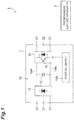
- a power conversion system 1 includes a power conversion apparatus 2 and a programming support apparatus 3.
- the power conversion apparatus 2 includes power conversion circuitry 10 for power conversion and control circuitry 100 controlling the power conversion circuitry 10.
- the power conversion circuitry 10 includes a rectifier circuit 11, a capacitor 12, an inverter circuit 13, an AC input terminal 21, and an AC output terminal 22.
- the rectifier circuit 11 is, for example, a diode bridge circuit, and converts AC power input to the AC input terminal 21 into a DC voltage and outputs the DC voltage to DC buses 14P and 14N.
- the capacitor 12 is connected between the DC buses 14P and 14N, and smooths the DC voltage between the DC buses 14P and 14N.
- the inverter circuit 13 is a circuit configured to convert DC power of the DC buses 14P and 14N into AC power and output the AC power to the AC output terminal 22.
- the inverter circuit 13 includes a plurality of switches 15 such as IGBTs, for example. It is possible to convert DC power into AC power by switching on/off of the plurality of switches 15.
- the power conversion circuitry 10 may be any circuitry as long as the circuitry can control output power.
- the power conversion circuitry 10 may be circuitry that converts DC input power into AC output power, circuitry that converts AC input power into DC output power, or circuitry that converts DC input power into DC output power.
- the power conversion circuitry 10 may be matrix converter circuitry that performs power conversion between AC input power and AC output power without converting AC power into DC power.
- the control circuitry 100 controls the inverter circuit 13 so as to execute power conversion by switching on/off of the switch 15.
- the control circuitry 100 includes program storage 111 and a control unit 112.
- the program storage 111 stores a control program configured to control the power conversion circuitry 10.
- the program storage 111 includes module storage 113 and sequence storage 114.
- the module storage 113 stores a plurality of program modules.
- the program module is, for example, an executable program including one or a plurality of functionalized information processing procedures.
- Various control programs can be configured by changing a combination of a plurality of program modules.
- the sequence storage 114 stores sequence data.
- the sequence data is data indicating an execution order of a plurality of program modules constituting the control program.
- FIG. 3 is a table illustrating sequence data. A numerical value of each cell in an upper row of FIG. 3 indicates an execution order. The numerical value of each cell in the lower row of FIG. 3 indicates an ID of a program module.
- the sequence storage 114 may be configured to store an ID of a user who has set sequence data in addition to the sequence data.
- control unit 112 controls the power conversion circuitry 10 according to the control program stored in the program storage 111.
- control unit 112 generates a gate driving signal according to the control program stored in the program storage 111, and outputs the generated gate driving signal to the switch 15 of the power conversion circuitry 10.
- the programming support apparatus 3 is an apparatus that supports generation of the above-described control program and performs information communication with the power conversion apparatus 2 in a wired or wireless manner.
- the programming support apparatus 3 is configured to execute at least reading the control program from the power conversion apparatus 2 and generating display data of a block diagram based on the control program.
- the block diagram is a diagram illustrating a content of the control program using a plurality of functional blocks and a link indicating input and output of information between the functional blocks.
- the generation of the display data may include generation of display data of a block diagram based on the sequence data stored in the power conversion apparatus 2 and a corresponding relationship between the functional block and the program module.
- the programming support apparatus 3 may be further configured to execute generating sequence data based on the arrangement of the functional blocks and the link of the block diagram.
- the programming support apparatus 3 may be further configured to execute storing the sequence data generated by the programming support apparatus 3 itself and an ID of a user stored in the programming support apparatus 3 itself in association with each other in the power conversion apparatus 2, and prohibiting the generation of display data based on the control program stored in the power conversion apparatus 2 when the ID stored in the power conversion apparatus 2 does not match the ID stored in the programming support apparatus 3 itself.
- the programming support apparatus 3 may be further configured to execute setting virtual input data for at least some of the functional blocks in the block diagram, executing any of a plurality of program modules corresponding to the plurality of program modules stored in the power conversion apparatus 2 (hereinafter referred to as "corresponding modules") in accordance with the sequence data and the virtual input data, and generating overwrite data for display of an execution result of the corresponding module together with the block diagram.
- corresponding modules a plurality of program modules corresponding to the plurality of program modules stored in the power conversion apparatus 2
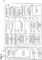
- the programming support apparatus 3 includes display data storage 214, block storage 212, a sequence data acquisition unit 219, a display data generation unit 221, and an image display unit 224.
- the display data storage 214 stores display data of a programming support screen (a screen for support of control program generation).
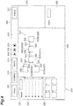
- FIG. 4 is a schematic diagram illustrating the programming support screen.
- a programming support screen 300 illustrated in FIG. 4 includes a tool bar 310, a block diagram display section 320, a block selection section 330, a property display section 340, and a condition input section 350.
- the tool bar 310 displays a plurality of tools.
- the plurality of tools includes, for example, a read button 311, a compile button 312, a write button 313, a continuous execution button 314, a step execution button 315, a stop button 316, and an add ID button 317.
- the read button 311 is a button configured to instruct reading of a control program from the power conversion apparatus 2.
- the compile button 312 is a button configured to instruct generation of sequence data based on a block diagram.
- the write button 313 is a button configured to instruct writing of sequence data to the power conversion apparatus 2.
- the continuous execution button 314 is a button configured to instruct execution of simulation in a continuous mode (to be described later).
- the step execution button 315 is a button configured to instruct execution of simulation in a step mode (to be described later).
- the stop button 316 is a button configured to instruct stop of simulation.
- the add ID button 317 is a button configured to instruct additional registration of an ID of a user in ID storage 211.
- the block diagram display section 320 is an area configured to display a block diagram 321.
- the block diagram 321 illustrates a content of a control program using a plurality of functional blocks 322 and a link 323 indicating input and output of information between the functional blocks 322.
- the functional block 322 acquires information and outputs information based on the acquired information.
- the functional block 322 may include at least one of an input terminal 324 associated with a program module for information input and an output terminal 325 associated with a program module for information output.
- the plurality of functional blocks 322 includes a signal input block 322A, a signal output block 322B, and an intermediate calculation block 322C.
- the signal input block 322A is a block configured to acquire a signal and has the output terminal 325.
- the output terminal 325 is associated with a program module configured to output information based on the acquired signal to another functional block 322.
- Specific examples of the signals to be acquired include signals from sensors inside and outside of the power conversion apparatus 2 or a command signal from the power conversion apparatus 2 or the like.
- the information based on the acquired signal may be numerical information indicating the acquired signal itself, or may be numerical information obtained by subjecting the signal to predetermined calculation (for example, multiplication by a gain).
- the signal output block 322B is a block configured to output a signal and has the input terminal 324.
- the input terminal 324 is associated with a program module configured to acquire information output from another functional block 322.
- the signal output block 322B outputs the signal based on the information acquired by the input terminal 324.
- Specific examples of the signals to be output include a frequency command signal for generation of a gate driving signal and the like.
- the signal based on the acquired information may be a signal indicating the acquired information itself or may be a signal indicating numerical information obtained by subjecting the information to predetermined calculation (for example, multiplication by a gain).
- the intermediate calculation block 322C has the input terminal 324 and the output terminal 325.
- the input terminal 324 is associated with a program module configured to acquire information output from another functional block 322.
- the output terminal 325 is associated with a program module configured to output information based on the information acquired by the input terminal 324 to another functional block 322.
- the information based on the acquired information may be the acquired numerical information itself or may be numerical information obtained by subjecting the numerical information to a predetermined calculation (for example, multiplication by a gain).
- the functional block 322 may include a plurality of the input terminals 324 and a plurality of the output terminals 325.
- the intermediate calculation block 322C may include the plurality of input terminals 324 and the single output terminal 325, and the output terminal 325 may be associated with a program module configured to output information based on a plurality of pieces of information acquired by each of the plurality of input terminals 324 to another functional block 322.
- Specific examples of the information based on the plurality of pieces of information include information obtained by adding the plurality of pieces of information and the like.
- the link 323 connects the output terminal 325 of one of the functional blocks 322 and the input terminal 324 of any of the others functional blocks 322, and indicates that information from the output terminal 325 is input to the functional block 322.
- the block selection section 330 is an area configured to select the functional block 322 to be added to the block diagram display section 320.
- the block selection section 330 includes a key input box 331, a category list 332, and a block list 333.
- the key input box 331 is a text box to input a key configured to search for a desired functional block 322 from the block storage 212.
- the category list 332 is a list displaying categories of the functional blocks 322.
- the block list 333 is a list displaying an icon of the functional block 322 corresponding to the key input to the key input box 331 among all the functional blocks 322 belonging to the category selected in the category list 332.
- the property display section 340 is an area displaying a property of the functional block 322 selected in the block diagram display section 320.
- the condition input section 350 is an area configured to input simulation conditions for the functional block 322 selected in the block diagram display section 320. Specific examples of the simulation conditions include a condition to specify the signal to be input to the signal input block 322A described above. The condition may be a numerical designation specifying a value of the signal or a waveform designation including a period and an amplitude.
- the block storage 212 stores the plurality of functional blocks 322 in association with any of a plurality of program modules.
- the block storage 212 stores identification information of the input terminal 324 of the functional block 322 and identification information of the program module for information input in association with each other, and stores identification information of the output terminal 325 of the functional block 322 and identification information of the program module for information output in association with each other.
- the sequence data acquisition unit 219 acquires the sequence data stored in the sequence storage 114 of the power conversion apparatus 2.
- the display data generation unit 221 generates display data of the block diagram 321 based on the control program stored in the program storage 111 of the power conversion apparatus 2 and stores the generated display data in the display data storage 214.
- the display data generation unit 221 generates the display data of the block diagram 321 based on the sequence data acquired by the sequence data acquisition unit 219 and a corresponding relationship between the functional block 322 of the block storage 212 and the program module.
- the display data generation unit 221 may generate the display data of the block diagram 321 such that the output terminal 325 of one of the functional blocks 322 and the input terminal 324 of any other functional block 322 are connected by the link 323.
- the display data generation unit 221 includes an arrangement setting unit 222 and a link data generation unit 223 as further divided constituent elements.
- the arrangement setting unit 222 sets an arrangement of the functional blocks 322.
- the link data generation unit 223 generates display data of the link 323. For example, when the program module associated with the input terminal 324 of the other functional block 322 is positioned next to the program module associated with the output terminal 325 of the one functional block 322 in the sequence data acquired by the sequence data acquisition unit 219, the arrangement setting unit 222 sets the arrangement of the functional blocks 322 such that a position of the one functional block 322 and a position of the other functional block 322 differ in a first direction (for example, the lateral direction in FIG.
- the link data generation unit 223 generates the display data of the link 323 such that the output terminal 325 of the one functional block 322 and the input terminal 324 of the other functional block 322 are connected to each other.
- "differ in the first direction” means that positions in the first direction are different from each other, and an arrangement relationship in a direction orthogonal to the first direction is not specified.
- the arrangement setting unit 222 sets the arrangement of the functional blocks 322 such that the position of the one functional block 322 and the position of the other functional block 322 differ in a second direction intersecting with the first direction (for example, the vertical direction in FIG. 4 ).
- the display data generation unit 221 may generate the display data of the block diagram 321 in accordance with a procedure tracing the execution order in the sequence data (that is, generate the display data of the block diagram 321 in order from the left side in FIG. 4 ), or may generate the display data of the block diagram 321 in accordance with a procedure tracing back the execution order in the sequence data (that is, generates the display data of the block diagram 321 in order from the right side in FIG. 4 ).
- the image display unit 224 displays the programming support screen 300 including the block diagram 321 according to the display data stored in the display data storage 214.
- the programming support apparatus 3 may further include the ID storage 211, an ID registration unit 216, a counterpart ID acquisition unit 217, and a security management unit 218.
- the ID storage 211 stores an ID of a user of the programming support apparatus 3 itself (the programming support apparatus 3 including the ID storage 211).
- the ID storage 211 may be configured to be capable of storing IDs of a plurality of users.
- the ID registration unit 216 acquires an ID of a user that has been additionally input and stores the acquired ID in the ID storage 211.
- the ID registration unit 216 displays a dialog box for input of an ID and a password of a user in response to clicking on the add ID button 317 (see FIG. 4 ).
- the ID and the password of the user have been issued to the power conversion apparatus 2 in advance, for example, by a manufacturer of the power conversion apparatus 2, and registered in a server or the like of the manufacturer.
- the ID registration unit 216 determines whether the ID can be registered, and stores the ID in the ID storage 211 if the ID can be registered. For example, the ID registration unit 216 determines that the ID can be registered when a combination of the input ID and password has been registered in the server or the like, and determines that the ID is prohibited from being registered when the combination is not registered in the server or the like.
- the counterpart ID acquisition unit 217 acquires an ID stored in the sequence storage 114 of the power conversion apparatus 2.
- the security management unit 218 prohibits the generation of the display data of the block diagram 321 based on the control program stored in the program storage 111 when the ID acquired by the counterpart ID acquisition unit 217 does not match the ID stored in the ID storage 211.
- the security management unit 218 prohibits the acquisition of sequence data by the sequence data acquisition unit 219.
- the security management unit 218 may be configured to permit the generation of the display data of the block diagram 321 based on the control program stored in the program storage 111 when the ID acquired by the counterpart ID acquisition unit 217 matches any one of the plurality of IDs stored in the ID storage 211.
- the security management unit 218 may be provided on the power conversion apparatus 2 side. In this case, the security management unit 218 prohibits, for example, transmission of the sequence data from the sequence storage 114 to the sequence data acquisition unit 219 when the ID stored in the sequence storage 114 does not match the ID stored in the ID storage 211.
- the programming support apparatus 3 may further include a display data editing unit 232, a compilation unit 225, sequence storage 215, a corresponding program storage 213, an input data setting unit 226, a mode setting unit 227, a simulation unit 228, a result display data generation unit 229, and a sequence data registration unit 231.
- the display data editing unit 232 changes the display data of the display data storage 214 according to an operation input to the programming support screen 300. For example, the display data editing unit 232 changes the display data such that the functional block 322 is added to the block diagram 321 according to a drag completion position when the functional block 322 has been dragged from the block list 333 to the block diagram display section 320. In addition, the display data editing unit 232 changes the display data such that the link 323 connecting the output terminal 325 and the input terminal 324 is added when a drag input from the output terminal 325 of one of the functional blocks 322 in the block diagram display section 320 to the input terminal 324 of the other functional block 322 has been made. In addition, the display data editing unit 232 changes the display data so as to delete the functional block 322 or the link 323 when an input of deleting the functional block 322 or the link 323 has been made in the block diagram display section 320.
- the compilation unit 225 performs compiling of generating sequence data based on the arrangement of the functional blocks 322 in the block diagram 321 and the link 323 and stores the generated sequence data in the sequence storage 215. For example, the compilation unit 225 generates the sequence data such that two program modules respectively associated with the output terminal 325 and the input terminal 324 connected by the link 323 are sequentially arranged. The arrangement of the functional blocks 322 and the link 323 are obtained from the display data storage 214, for example. The compiling is performed based on the correspondence between the functional block 322 and the program module stored in the block storage 212, for example. Incidentally, a process executed by the display data generation unit 221 corresponds to "decompiling" with respect to "compiling" executed by the compilation unit 225.
- the corresponding program storage 213 stores a plurality of program modules (corresponding modules) corresponding to the plurality of program modules stored in the module storage 113.
- the corresponding module is a simulation program module in the programming support apparatus 3, and is obtained by modifying, for example, the program module stored in the module storage 113 so as to be virtually executable by the programming support apparatus 3.
- a "virtual execution" means to execute the program module without operating the power conversion apparatus 2.
- the input data setting unit 226 sets virtual input data for at least some of the functional blocks 322 in the block diagram 321. For example, the input data setting unit 226 sets input data based on the content input to the condition input section 350. When the waveform designation including the period and the amplitude has been input in the condition input section 350, the input data setting unit 226 may be configured to set input data of a waveform based on the waveform designation.
- the mode setting unit 227 sets an execution mode of the simulation to one of a plurality of modes including a continuous mode and a step mode.
- the continuous mode is an execution mode in which execution of a series of program modules in accordance with sequence data is repeated.
- the step mode is an execution mode in which execution of a program module is interrupted whenever one or more program modules (hereinafter referred to as "a set of program modules") are executed.
- the mode setting unit 227 sets the execution mode to the continuous mode when the continuous execution button 314 has been clicked, and sets the execution mode to the step mode when the step execution button 315 has been clicked.
- the set of program modules to be executed in the step mode include program modules for one control cycle (a series of program modules repeated in the continuous mode). That is, the step mode may be set such that the execution of the program module is interrupted at every control cycle.
- the set of program modules may be program modules associated with the single functional block 322. That is, the step mode may be set such that the execution of the program module is interrupted for each of the functional blocks 322.
- the mode setting unit 227 may be configured to be capable of customizing a set of program modules according to user's designation.
- the simulation unit 228 executes the simulation in the execution mode set by the mode setting unit 227. Specifically, the simulation unit 228 executes the program module stored in the corresponding program storage 213 in accordance with the sequence data generated by the compilation unit 225 and the virtual input data set by the input data setting unit 226.
- the result display data generation unit 229 generates overwrite data for display of the execution result of the program module by the simulation unit 228 on the block diagram display section 320 and stores the generated overwrite data in the display data storage 214. For example, the result display data generation unit 229 generates the overwrite data such that a numerical value calculated by the execution of the program module is displayed in the vicinity of the functional block 322 corresponding to the program module.
- the sequence data registration unit 231 stores the sequence data stored in the sequence storage 215 by the compilation unit 225 and any of the IDs stored in the ID storage 211 in the sequence storage 114 of the power conversion apparatus 2 to be associated with each other.
- FIG. 5 is a block diagram illustrating a hardware configuration of the power conversion system 1.
- the control circuitry 100 includes a processor 191, a memory 192, a storage 193, a gate drive circuit 194, and a communication port 195.
- the storage 193 is a computer-readable nonvolatile storage medium (for example, a hard disk or a flash memory).
- the storage 193 includes a storage area of a program configured to construct the control unit 112 and storage areas allocated to the module storage 113 and the sequence storage 114.
- the memory 192 temporarily stores a program loaded from the storage 193, a result of calculation by the processor 191, and the like.
- the processor 191 functions as the control unit 112 by executing the above-described program in cooperation with the memory 192.
- the gate drive circuit 194 outputs a gate driving signal to the inverter circuit 13 in accordance with a command from the processor 191.
- the communication port 195 transmits and receives data to and from the programming support apparatus 3 in accordance with the command from
- the programming support apparatus 3 includes programming support circuitry 200.
- the programming support circuitry 200 includes a processor 291, a memory 292, storage 293, a monitor 294, an input device 295, a communication port 296, and a network adapter 297.
- the storage 293 is a computer-readable nonvolatile storage medium (for example, a hard disk or a flash memory). The storage 293 stores a program to cause an apparatus to execute reading the control program from the power conversion apparatus 2 and generating the display data of the block diagram 321 based on the control program.
- the program may be configured to cause the programming support apparatus 3 to generate the display data of the block diagram 321 based on the sequence data stored in the power conversion apparatus 2 and the corresponding relationship between the functional block 322 and the program module.
- the program may be configured to cause the programming support apparatus 3 to generate the display data of the block diagram 321 such that the output terminal 325 of one of the functional blocks 322 and the input terminal 324 of any other functional block 322 are connected by the link 323.
- the program may be configured, when the program module associated with the input terminal 324 of the other functional block 322 is positioned next to the program module associated with the output terminal 325 of the one functional block 322 in the sequence data stored in the power conversion apparatus 2, to cause the programming support apparatus 3 to set the arrangement of the functional blocks 322 such that a position of one of the functional blocks 322 and a position of any other functional block 322 differ in the first direction , and to cause the programming support apparatus 3 to generate the display data of the link 323 such that the output terminal 325 of the one functional blocks 322 and the input terminal 324 of the other functional block 322 are connected.
- the program may be configured to, when the program module associated with the output terminal 325 of the other functional block is positioned next to the program module associated with the input terminal 324 or the output terminal 325 of the one functional block 322 in the sequence data stored in the power conversion apparatus 2, cause the programming support apparatus 3 to set the arrangement of the functional blocks 322 such that a position of one of the functional blocks 322 and a position of any other functional block 322 differ in the second direction intersecting with the first direction.
- the program may be further configured to cause the programming support apparatus 3 to generate the sequence data based on the arrangement of the functional blocks 322 in the block diagram 321 and the link 323.
- the program may be further configured to cause the programming support apparatus 3 to execute storing the sequence data generated by the programming support apparatus 3 itself and an ID of a user stored in the programming support apparatus 3 itself in association with each other in the power conversion apparatus 2, and prohibiting the generation of display data based on the control program stored in the power conversion apparatus 2 when the ID stored in the power conversion apparatus 2 does not match the ID stored in the programming support apparatus 3 itself.
- the program is configured to be capable of storing IDs of a plurality of users in the programming support apparatus 3 itself, and may be configured to permit generation of display data based on the control program stored in the power conversion apparatus 2 when the ID stored in the power conversion apparatus matches any one of the IDs stored in the programming support apparatus 3.
- the program may be further configured to cause the programming support apparatus 3 to execute, for at least some of the functional blocks 322 in the block diagram 321, setting the virtual input data executing any of the corresponding modules in accordance with the sequence data and the virtual input data, and generating overwrite data for display of an execution result of the corresponding module together with the block diagram 321.
- the program may be configured to cause the programming support apparatus 3 to set the input data of the waveform based on the waveform designation including the cycle and the amplitude.
- the program may be configured to cause the programming support apparatus 3 to execute setting the execution mode of the simulation in the programming support apparatus 3 to any of the plurality of modes including the continuous mode and the step mode and executing the corresponding program module in the set execution mode.
- the storage 293 includes a storage area allocated to the ID storage 211, the block storage 212, the corresponding program storage 213, the display data storage 214, and the sequence storage 215 among the plurality of elements of the programming support apparatus 3 illustrated in FIG. 2 , and a storage area of a program to construct the other elements.
- the monitor 294 is, for example, an image display apparatus such as a liquid crystal monitor and is used as, for example, the image display unit 224.
- the input device 295 is an information input device such as a keypad, for example, and is used for an operation input to the programming support screen 300 displayed on the monitor 294.
- the monitor 294 and the input device 295 may be integrated such as a so-called touch panel.
- the communication port 296 transmits and receives data to and from the communication port 195 of the power conversion apparatus 2 in response to a command from the processor 291.
- the network adapter 297 is connected to a server 4 or the like of a manufacturer of the power conversion apparatus 2 via a network line NW such as the Internet and transmits and receives data to and from the server 4 in response to a command from the processor 291.
- the network adapter 297 is used for the determination on whether an ID can be registered performed by the ID registration unit 216, or the like.
- the network line NW may be interposed between the communication port 296 and the communication port 195.
- the procedure includes: a procedure (decompiling procedure) of generating the display data of the block diagram 321 based on the control program stored in the power conversion apparatus 2; a procedure (compiling procedure) of generating sequence data based on the arrangement of the functional blocks 322 and the link 323 in the block diagram 321; a procedure (simulation procedure) of simulating the sequence data generated in the compiling procedure; and a procedure (sequence registration procedure) of storing the sequence data generated by the compiling procedure in the power conversion apparatus 2.
- the programming support apparatus 3 sequentially executes Steps S01 and S02.
- Step S01 the counterpart ID acquisition unit 217 acquires the ID stored in the sequence storage 114 of the power conversion apparatus 2.
- the security management unit 218 confirms whether an ID acquired by the counterpart ID acquisition unit 217 matches one of the plurality of IDs stored in the ID storage 211. If it is determined in Step S02 that the ID acquired by the counterpart ID acquisition unit 217 does not match any of the plurality of IDs stored in the ID storage 211, the security management unit 218 prohibits the acquisition of the sequence data performed by the sequence data acquisition unit 219. As a result, the programming support apparatus 3 stops the decompiling without executing Steps S03 to S09.
- Step S02 If it is determined in Step S02 that the ID acquired by the counterpart ID acquisition unit 217 matches any one of the plurality of IDs stored in the ID storage 211, the programming support apparatus 3 executes Step S03.
- Step S03 the sequence data acquisition unit 219 acquires the sequence data stored in the sequence storage 114 of the power conversion apparatus 2.
- Step S04 the display data generation unit 221 selects the first program module from the sequence data acquired in Step S03.
- Step S05 the display data generation unit 221 specifies any functional block 322 with which the program module that has been selected in Step S04 is associated.
- the display data generation unit 221 refers to the block storage 212 to specify which terminal (the input terminal 324 or the output terminal 325) of which functional block 322 the program module is associated with.
- Step S06 the display data generation unit 221 updates the display data of the block diagram 321 based on the sequence data acquired in Step S03, and the corresponding relationship between the functional block 322 and the program module specified in Step S05 and stores the updated display data in the display data storage 214. A specific processing content of Step S06 will be described later.
- Step S07 the display data generation unit 221 confirms whether generation of display data of the entire control program has been completed. For example, the display data generation unit 221 confirms whether program modules that have not been selected as the object to be executed in Steps S05 and S06 remain in the sequence data.
- Step S07 If it is determined in Step S07 that the generation of display data of the entire control program has not been completed, the programming support apparatus 3 executes Step S08.
- Step S08 the display data generation unit 221 selects the immediately subsequent program module (i.e., the next program module in the sequence data). Thereafter, the programming support apparatus 3 returns the process to Step S05. Thereafter, the programming support apparatus 3 repeats the selection of the program module and the update of the display data of the block diagram 321 until the generation of display data of the entire control program is completed.
- Step S09 the image display unit 224 displays the block diagram 321 based on the display data, generated by repeating Steps S05, S06, S07, and S08, on the programming support screen 300.
- the decompiling procedure is completed as above.
- FIG. 7 is a flowchart illustrating an update procedure of the display data in Step S06.
- the programming support apparatus 3 first executes Step S11.
- Step S11 the arrangement setting unit 222 confirms whether it is necessary to add the functional block 322 to the block diagram 321. Specifically, if the functional block 322 associated with the currently selected program module exists in the display data of the block diagram 321, the arrangement setting unit 222 determines that it is unnecessary to add the functional block 322 and, if the functional block 322 does not exist in the display data of the block diagram 321, the arrangement setting unit 222 determines that it is necessary to add the functional block 322.
- Step S11 If it is determined in Step S11 that it is unnecessary to add the functional block 322, the programming support apparatus 3 completes the update procedure of the display data. If it is determined in Step S11 that it is necessary to add the functional block 322, the programming support apparatus 3 executes Step S12. In Step S12, the arrangement setting unit 222 confirms whether the functional block 322 other than the functional block 322 as an object to be added exists in the display data of the block diagram 321.
- Step S12 If it is determined in Step S12 that there is no other functional block 322, the programming support apparatus 3 executes Step S13.
- Step S13 the arrangement setting unit 222 adds the functional block 322 as the object to be added to the display data of the block diagram 321.
- Step S14 the arrangement setting unit 222 confirms whether there is an information input/output relationship between the functional block 322 as the object to be added and the other functional block 322. For example, if the selected program module is associated with the input terminal 324 of the functional block 322 as the object to be added and a program module immediately before the program module (i.e., the immediately preceding program module in the sequence data) is associated with the output terminal 325 of the other functional block 322, the arrangement setting unit 222 determines that there is the input/output relationship. When the selected program module is associated with the output terminal 325 of the functional block 322 as the object to be added, the arrangement setting unit 222 determines that there is no input/output relationship.
- Step S15 the arrangement setting unit 222 adds the functional block 322 as the object to the display data in an arrangement of deviating in the second direction with respect to the functional block 322 associated with the preceding program module.
- Step S16 the display data generation unit 221 adds the functional block 322 as the object to the display data in an arrangement of deviating in the first direction with respect to the functional block 322 associated with the preceding program module.
- Step S17 the link data generation unit 223 adds the display data of the link 323 to connect the output terminal 325 associated with the immediately preceding program module and the input terminal 324 associated with the selected program module. The update procedure of the display data is completed as above.
- the last program module may be selected instead of the first program module.
- the immediately preceding program module e.g., the previous program module in the sequence data
- Step S08 instead of the immediately subsequent program module.
- Step S14 if the selected program module is associated with the output terminal 325 of the functional block 322 as the object to be added and a program module immediately subsequent the program module (immediately next program module in the sequence data) is associated with the input terminal 324 of the other functional block 322, the arrangement setting unit 222 determines that there is the input/output relationship.
- the arrangement setting unit 222 determines that there is no input/output relationship.
- Step S21 the display data editing unit 232 confirms whether an operation input for changing the display of the block diagram 321 (hereinafter referred to as an "editing input") has been made on the programming support screen 300.
- Step S21 If it is determined in Step S21 that the editing input has been made, the programming support apparatus 3 sequentially executes Steps S22 and S23.
- Step S22 the display data editing unit 232 updates the display data of the block diagram 321 according to the editing input and stores the updated display data in the display data storage 214.
- Step S23 the image display unit 224 displays the block diagram 321 on the programming support screen 300 based on the display data stored in the display data storage 214.
- Step S24 the programming support apparatus 3 executes Step S24. If it is determined in Step S21 that no editing input has been made, the programming support apparatus 3 executes Step S24 without executing Steps S22 and S23.
- the compilation unit 225 confirms whether there is a compilation execution command (for example, clicking of the compile button 312). If it is determined in Step S24 that there is no compilation execution command, the programming support apparatus 3 returns the process to Step S21. Thereafter, updating of the display of the block diagram 321 according to the operation input to the programming support screen 300 is repeated until it is determined that there is a compilation execution command.
- Step S25 the compilation unit 225 generates sequence data based on the arrangement of the functional blocks 322 in the block diagram 321 and the link 323 and stores the generated sequence data in the sequence storage 215. For example, the compilation unit 225 generates the sequence data such that two program modules respectively associated with the output terminal 325 and the input terminal 324 connected by the link 323 are sequentially arranged. The compiling procedure is completed as above.
- Step S31 the display data editing unit 232 confirms whether an input to the condition input section 350 (hereinafter referred to as a "condition input") has been made. If it is determined in Step S31 that the condition input has been made, the programming support apparatus 3 executes Step S32.
- Step S32 the display data editing unit 232 updates the display data of the condition input section 350 according to the condition input and stores the updated display data in the display data storage 214.
- Step S33 the image display unit 224 updates the display of the condition input section 350 based on the display data stored in the display data storage 214.
- Step S34 the programming support apparatus 3 executes Step S34. If it is determined in Step S31 that the condition input has not been made, the programming support apparatus 3 executes Step S34 without executing Steps S32 and S33.
- the mode setting unit 227 confirms the presence or absence of a simulation start command (for example, clicking of the continuous execution button 314 or the step execution button 315). If it is determined in Step S34 that there is no simulation start command, the programming support apparatus 3 returns the process to Step S31. Thereafter, updating of the display of the condition input section 350 according to the condition input is repeated until it is determined that there is a simulation start command.
- Step S34 the programming support apparatus 3 sequentially executes Steps S35 and S36.
- Step S35 the input data setting unit 226 sets the input data based on the content input to the condition input section 350.
- Step S36 the mode setting unit 227 sets a simulation execution mode to one of the plurality of modes including the continuous mode and the step mode. For example, the mode setting unit 227 sets the execution mode to the continuous mode when the continuous execution button 314 has been clicked for the simulation start command, and sets the execution mode to the step mode when the step execution button 315 has been clicked for the simulation start command.
- Step S37 the simulation unit 228 selects a program module as an object to be executed from the corresponding program storage 213 according to the sequence data stored in the sequence storage 215.
- Step S38 the simulation unit 228 executes the program module selected in Step S37.
- Step S39 the result display data generation unit 229 generates overwrite data to display an execution result of the program module performed by the simulation unit 228 together with the block diagram 321 (for example, in the block diagram 321), and stores the generated overwrite data in the display data storage 214.
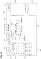
- Step S41 the image display unit 224 updates the display of the block diagram display section 320 based on the display data stored in the display data storage 214. As a result, result data 361 indicating the execution result of the program module is displayed on the block diagram display section 320 (see FIG. 10 ).
- Step S42 the simulation unit 228 confirms whether the execution mode is the continuous mode. If it is determined in Step S42 that the execution mode is the step mode, the programming support apparatus 3 executes Step S43.
- Step S43 the simulation unit 228 confirms whether execution of the set of program modules has been completed. If it is determined in Step S43 that the execution of the set of program modules has not been completed, the programming support apparatus 3 returns the process to Step S37. Thereafter, selection and execution of a program module according to the sequence data are repeated until execution of the set of program modules is completed.
- Step S43 If it is determined in Step S43 that the execution of the set of program modules has been completed, the programming support apparatus 3 executes Step S44. In Step S44, the simulation unit 228 interrupts the execution of the program module. Thereafter, the programming support apparatus 3 returns the process to Step S31.
- Step S45 the simulation unit 228 confirms the presence or absence of a simulation stop command (for example, clicking of the stop button 316). If it is determined in Step S45 that there is no simulation stop command, the programming support apparatus 3 returns the process to Step S37. Thereafter, selection and execution of a program module according to the sequence data are repeated until it is determined that there is a simulation stop command. If it is determined in Step S45 that there is a simulation stop command, the programming support apparatus 3 stops the process. The simulation procedure is completed as above.
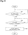
- Step S51 the sequence data registration unit 231 waits for storage of sequence data, which needs to be stored in the sequence storage 114, in the sequence storage 215.
- Step S52 the sequence data registration unit 231 waits for a sequence data registration command (for example, clicking of the write button 313).
- Step S53 the sequence data registration unit 231 stores the sequence data stored in the sequence storage 215 by the compilation unit 225 and any of the IDs stored in the ID storage 211 in the sequence storage 114 of the power conversion apparatus 2 to be associated with each other.
- the sequence registration procedure is completed as above.
- the power conversion system 1 includes: the power conversion apparatus 2 including the power conversion circuitry 10, the program storage 111 that stores the control program configured to control the power conversion circuitry 10, and the control unit 112 that controls the power conversion circuitry 10 according to the control program; and the programming support apparatus 3 connected to the power conversion apparatus 2.
- the programming support apparatus 3 includes the display data generation unit 221 that generates the display data of the block diagram 321 illustrating the content of the control program using the plurality of functional blocks 322 and the link 323 indicating input and output of information between the functional blocks 322 based on the control program stored in the program storage 111.
- the content of the control program stored in the power conversion apparatus 2 can be easily displayed as information flow between the functional blocks 322 by the programming support apparatus 3. Therefore, it is advantageous for reduction of a burden on work of editing the control program.
- the program storage 111 may include the module storage 113 that stores the plurality of program modules, and the sequence storage 114 that stores the sequence data indicating the execution order of the plurality of program modules.
- the programming support apparatus 3 may further include the block storage 212 that stores the plurality of functional blocks 322 in association with any of the plurality of program modules.
- the display data generation unit 221 may generate the display data of the block diagram 321 based on the sequence data stored in the sequence storage 215 and the corresponding relationship between the functional block 322 of the block storage 212 and the program module. In this case, it is possible to generate display data of the information flow between the functional blocks 322 while suppressing an increase in the amount of information to be stored on the power conversion apparatus 2 side.
- the functional block 322 may include at least one of the input terminal 324 associated with the program module for information input and the output terminal 325 associated with the program module for information output, and the display data generation unit 221 may generate the display data of the block diagram 321 such that the output terminal 325 of one of the functional blocks 322 and the input terminal 324 of any other functional block 322 are connected by the link 323.
- the display data generation unit 221 may generate the display data of the block diagram 321 such that the output terminal 325 of one of the functional blocks 322 and the input terminal 324 of any other functional block 322 are connected by the link 323.
- the display data generation unit 221 may include the arrangement setting unit 222 that sets the arrangement of the functional blocks 322, and the link data generation unit 223 that generates the display data of the link.
- the arrangement setting unit 222 may set the arrangement of the functional blocks 322 such that the position of the one functional block 322 and the position of the other functional block 322 differ in the first direction
- the link data generation unit 223 may generate the display data of the link 323 such that the output terminal 325 of the one functional block 322 and the input terminal 324 of the other functional block 322 are connected to each other.
- the content of the control program can be more easily grasped by arranging the functional blocks 322 along the flow of information.
- the arrangement setting unit may set the arrangement of the functional blocks 322 such that the position of the one functional block 322 and the position of the other functional block 322 differ in the second direction intersecting with the first direction.
- the content of the control program can be more easily grasped by displaying the flow of a plurality of pieces of information in parallel.
- the programming support apparatus 3 may further include the compilation unit 225 that generates the sequence data based on the arrangement of the functional blocks 322 in the block diagram 321 and the link 323. In this case, the editing result of the control program on the block diagram 321 can be easily reflected on the sequence data.
- the sequence storage 215 may be configured to store an ID of a user who has generated the sequence data in addition to the sequence data.
- the programming support apparatus 3 may further include the ID storage 211 that stores an ID of a user of the own apparatus and the sequence data registration unit 231 that stores the sequence data generated by the compilation unit 225 and any of the IDs stored in the ID storage 211 in the sequence storage 215 to be associated with each other.
- At least one of the programming support apparatus 3 and the power conversion apparatus 2 may further include the security management unit 218 that prohibits generation of display data based on the control program stored in the program storage 111 when the ID stored in the sequence storage 215 does not match the ID stored in the ID storage 211. In this case, the information in the power conversion apparatus 2 can be protected with high reliability.
- the ID storage 211 may be configured to be capable of storing IDs of a plurality of users.
- the security management unit 218 may be provided in the programming support apparatus 3 and configured to permit generation of display data based on the control program stored in the program storage 111 when the ID stored in the sequence storage 114 matches any of the IDs stored in the ID storage 211. In this case, it is possible to edit the control program of the plurality of power conversion apparatuses 2 with the single programming support apparatus 3.
- the programming support apparatus 3 may further include: the input data setting unit 226 that sets the virtual input data for at least some of the functional blocks 322 in the block diagram 321; the corresponding program storage 213 that stores a plurality of program modules respectively corresponding to the plurality of program modules stored in the module storage 113; the simulation unit 228 that executes the program module stored in the corresponding program storage 213 based on the sequence data generated by the compilation unit 225 and the virtual input data set by the input data setting unit 226; and the result display data generation unit 229 that generates the overwrite data configured to display the execution result of the program module by the simulation unit 228 together with the block diagram 321. In this case, it is possible to verify a new control program without operating the power conversion apparatus 2.
- the input data setting unit 226 may be configured to set the input data of the waveform based on the waveform designation including the cycle and the amplitude. In this case, it is possible to verify the new control program under more diverse conditions by making it possible to set the input data of the waveform.
- the programming support apparatus 3 may further include the mode setting unit 227 that sets the simulation execution mode to any of the plurality of modes including the continuous mode in which execution of a series of program modules according to sequence data is repeated and the step mode in which execution of a program module is interrupted whenever one or more program modules are executed.
- the simulation unit 228 may execute the program module stored in the corresponding program storage 213 in the execution mode set by the mode setting unit 227. In this case, it is possible to verify a new control program in more detail by allowing simulation in the step mode.
Landscapes
- Engineering & Computer Science (AREA)
- Software Systems (AREA)
- Physics & Mathematics (AREA)
- General Physics & Mathematics (AREA)
- Theoretical Computer Science (AREA)
- General Engineering & Computer Science (AREA)
- Power Engineering (AREA)
- Automation & Control Theory (AREA)
- Programmable Controllers (AREA)
- Inverter Devices (AREA)
Abstract
Description
- The present disclosure relates to a power conversion system, a programming support apparatus, a programming support method, a program, and a storage medium.
- Japanese Patent No.
5018477 - The present disclosure provides a power conversion system, a programming support apparatus, a programming support method, a program, and a storage medium which are effective for reduction of a work burden of editing a control program for a power conversion apparatus.
- A power conversion system according to an aspect of the present disclosure includes: a power conversion apparatus including power conversion circuitry, program storage that stores a control program configured to control the power conversion circuitry, and a control unit that controls the power conversion circuitry according to the control program; and a programming support apparatus connected to the power conversion apparatus. The programming support apparatus includes a display data generation unit that generates display data of a block diagram illustrating a content of the control program using a plurality of functional blocks and a link indicating input and output of information between the functional blocks based on the control program stored in the program storage.
- A programming support apparatus according to another aspect of the present disclosure includes: a program reading unit that reads a control program configured to control of power conversion circuitry from a power conversion apparatus having the power conversion circuitry; and a display data generation unit that generates display data of a block diagram illustrating a content of the control program using a plurality of functional blocks and a link indicating input and output of information between the functional blocks based on the control program read by the program reading unit.
- A programming support method according to still another aspect of the present disclosure includes: reading a control program configured to control of power conversion circuitry from a power conversion apparatus having the power conversion circuitry; and generating display data of a block diagram illustrating a content of the control program using a plurality of functional blocks and a link indicating input and output of information between the functional blocks based on the control program.
- A program according to a still another aspect of the present disclosure is a program for causing an apparatus to execute: reading a control program configured to control of power conversion circuitry from a power conversion apparatus having the power conversion circuitry; and generating display data of a block diagram illustrating a content of the control program using a plurality of functional blocks and a link indicating input and output of information between the functional blocks based on the control program.
- A storage medium according to still another aspect of the present disclosure is a computer readable storage medium storing a program for causing an apparatus to execute: reading a control program configured to control of power conversion circuitry from a power conversion apparatus having the power conversion circuitry; and generating display data of a block diagram illustrating a content of the control program using a plurality of functional blocks and a link indicating input and output of information between the functional blocks based on the control program.
- According to the present disclosure, it is possible to provide the power conversion system, the programming support apparatus, the programming support method, the program, and the storage medium which are effective for reduction of the burden on work of editing the control program for the power conversion apparatus.
-
-
FIG. 1 is a schematic diagram illustrating a schematic configuration of a power conversion system; -
FIG. 2 is a block diagram illustrating a functional configuration of the power conversion system; -
FIG. 3 is a table illustrating sequence data; -
FIG. 4 is a schematic diagram illustrating a programming support screen; -
FIG. 5 is a block diagram illustrating a hardware configuration of the power conversion system; -
FIG. 6 is a flowchart illustrating a decompiling procedure; -
FIG. 7 is a flowchart illustrating a display data generation procedure; -
FIG. 8 is a flowchart illustrating a compilation procedure; -
FIG. 9 is a flowchart illustrating a simulation procedure; -
FIG. 10 is a schematic diagram illustrating a programming support screen during simulation; and -
FIG. 11 is a flowchart illustrating a sequence data registration procedure. - Hereinafter, an embodiment will be described in detail with reference to the drawings. The same elements or elements having the same function will be denoted by the same reference signs in the description, and redundant descriptions will be appropriately omitted. A power conversion system according to the present embodiment is a system that generates desired AC power and outputs the generated AC power to a load (for example, an electric motor).
- As illustrated in
FIG. 1 , apower conversion system 1 includes apower conversion apparatus 2 and aprogramming support apparatus 3. Thepower conversion apparatus 2 includespower conversion circuitry 10 for power conversion andcontrol circuitry 100 controlling thepower conversion circuitry 10. Thepower conversion circuitry 10 includes arectifier circuit 11, acapacitor 12, aninverter circuit 13, anAC input terminal 21, and anAC output terminal 22. Therectifier circuit 11 is, for example, a diode bridge circuit, and converts AC power input to theAC input terminal 21 into a DC voltage and outputs the DC voltage toDC buses capacitor 12 is connected between theDC buses DC buses inverter circuit 13 is a circuit configured to convert DC power of theDC buses AC output terminal 22. Theinverter circuit 13 includes a plurality ofswitches 15 such as IGBTs, for example. It is possible to convert DC power into AC power by switching on/off of the plurality ofswitches 15. - Incidentally, the
power conversion circuitry 10 may be any circuitry as long as the circuitry can control output power. For example, thepower conversion circuitry 10 may be circuitry that converts DC input power into AC output power, circuitry that converts AC input power into DC output power, or circuitry that converts DC input power into DC output power. In addition, thepower conversion circuitry 10 may be matrix converter circuitry that performs power conversion between AC input power and AC output power without converting AC power into DC power. - The
control circuitry 100 controls theinverter circuit 13 so as to execute power conversion by switching on/off of theswitch 15. As illustrated inFIG. 2 , thecontrol circuitry 100 includesprogram storage 111 and acontrol unit 112. Theprogram storage 111 stores a control program configured to control thepower conversion circuitry 10. For example, theprogram storage 111 includesmodule storage 113 andsequence storage 114. - The
module storage 113 stores a plurality of program modules. The program module is, for example, an executable program including one or a plurality of functionalized information processing procedures. Various control programs can be configured by changing a combination of a plurality of program modules. - The
sequence storage 114 stores sequence data. The sequence data is data indicating an execution order of a plurality of program modules constituting the control program.FIG. 3 is a table illustrating sequence data. A numerical value of each cell in an upper row ofFIG. 3 indicates an execution order. The numerical value of each cell in the lower row ofFIG. 3 indicates an ID of a program module. Thesequence storage 114 may be configured to store an ID of a user who has set sequence data in addition to the sequence data. - Returning to
FIG. 2 , thecontrol unit 112 controls thepower conversion circuitry 10 according to the control program stored in theprogram storage 111. For example, thecontrol unit 112 generates a gate driving signal according to the control program stored in theprogram storage 111, and outputs the generated gate driving signal to theswitch 15 of thepower conversion circuitry 10. - The
programming support apparatus 3 is an apparatus that supports generation of the above-described control program and performs information communication with thepower conversion apparatus 2 in a wired or wireless manner. Theprogramming support apparatus 3 is configured to execute at least reading the control program from thepower conversion apparatus 2 and generating display data of a block diagram based on the control program. The block diagram is a diagram illustrating a content of the control program using a plurality of functional blocks and a link indicating input and output of information between the functional blocks. The generation of the display data may include generation of display data of a block diagram based on the sequence data stored in thepower conversion apparatus 2 and a corresponding relationship between the functional block and the program module. - The
programming support apparatus 3 may be further configured to execute generating sequence data based on the arrangement of the functional blocks and the link of the block diagram. Theprogramming support apparatus 3 may be further configured to execute storing the sequence data generated by theprogramming support apparatus 3 itself and an ID of a user stored in theprogramming support apparatus 3 itself in association with each other in thepower conversion apparatus 2, and prohibiting the generation of display data based on the control program stored in thepower conversion apparatus 2 when the ID stored in thepower conversion apparatus 2 does not match the ID stored in theprogramming support apparatus 3 itself. Theprogramming support apparatus 3 may be further configured to execute setting virtual input data for at least some of the functional blocks in the block diagram, executing any of a plurality of program modules corresponding to the plurality of program modules stored in the power conversion apparatus 2 (hereinafter referred to as "corresponding modules") in accordance with the sequence data and the virtual input data, and generating overwrite data for display of an execution result of the corresponding module together with the block diagram. - For example, the
programming support apparatus 3 includesdisplay data storage 214,block storage 212, a sequencedata acquisition unit 219, a displaydata generation unit 221, and animage display unit 224. Thedisplay data storage 214 stores display data of a programming support screen (a screen for support of control program generation). -
FIG. 4 is a schematic diagram illustrating the programming support screen. Aprogramming support screen 300 illustrated inFIG. 4 includes atool bar 310, a blockdiagram display section 320, ablock selection section 330, aproperty display section 340, and acondition input section 350. Thetool bar 310 displays a plurality of tools. The plurality of tools includes, for example, aread button 311, a compilebutton 312, awrite button 313, acontinuous execution button 314, astep execution button 315, astop button 316, and anadd ID button 317. Theread button 311 is a button configured to instruct reading of a control program from thepower conversion apparatus 2. The compilebutton 312 is a button configured to instruct generation of sequence data based on a block diagram. Thewrite button 313 is a button configured to instruct writing of sequence data to thepower conversion apparatus 2. Thecontinuous execution button 314 is a button configured to instruct execution of simulation in a continuous mode (to be described later). Thestep execution button 315 is a button configured to instruct execution of simulation in a step mode (to be described later). Thestop button 316 is a button configured to instruct stop of simulation. Theadd ID button 317 is a button configured to instruct additional registration of an ID of a user inID storage 211. - The block
diagram display section 320 is an area configured to display a block diagram 321. The block diagram 321 illustrates a content of a control program using a plurality offunctional blocks 322 and alink 323 indicating input and output of information between thefunctional blocks 322. Thefunctional block 322 acquires information and outputs information based on the acquired information. Thefunctional block 322 may include at least one of aninput terminal 324 associated with a program module for information input and anoutput terminal 325 associated with a program module for information output. For example, the plurality offunctional blocks 322 includes asignal input block 322A, asignal output block 322B, and anintermediate calculation block 322C. - The
signal input block 322A is a block configured to acquire a signal and has theoutput terminal 325. Theoutput terminal 325 is associated with a program module configured to output information based on the acquired signal to anotherfunctional block 322. Specific examples of the signals to be acquired include signals from sensors inside and outside of thepower conversion apparatus 2 or a command signal from thepower conversion apparatus 2 or the like. The information based on the acquired signal may be numerical information indicating the acquired signal itself, or may be numerical information obtained by subjecting the signal to predetermined calculation (for example, multiplication by a gain). - The
signal output block 322B is a block configured to output a signal and has theinput terminal 324. Theinput terminal 324 is associated with a program module configured to acquire information output from anotherfunctional block 322. Thesignal output block 322B outputs the signal based on the information acquired by theinput terminal 324. Specific examples of the signals to be output include a frequency command signal for generation of a gate driving signal and the like. The signal based on the acquired information may be a signal indicating the acquired information itself or may be a signal indicating numerical information obtained by subjecting the information to predetermined calculation (for example, multiplication by a gain). - The
intermediate calculation block 322C has theinput terminal 324 and theoutput terminal 325. Theinput terminal 324 is associated with a program module configured to acquire information output from anotherfunctional block 322. Theoutput terminal 325 is associated with a program module configured to output information based on the information acquired by theinput terminal 324 to anotherfunctional block 322. The information based on the acquired information may be the acquired numerical information itself or may be numerical information obtained by subjecting the numerical information to a predetermined calculation (for example, multiplication by a gain). - The
functional block 322 may include a plurality of theinput terminals 324 and a plurality of theoutput terminals 325. For example, theintermediate calculation block 322C may include the plurality ofinput terminals 324 and thesingle output terminal 325, and theoutput terminal 325 may be associated with a program module configured to output information based on a plurality of pieces of information acquired by each of the plurality ofinput terminals 324 to anotherfunctional block 322. Specific examples of the information based on the plurality of pieces of information include information obtained by adding the plurality of pieces of information and the like. - The
link 323 connects theoutput terminal 325 of one of thefunctional blocks 322 and theinput terminal 324 of any of the othersfunctional blocks 322, and indicates that information from theoutput terminal 325 is input to thefunctional block 322. - The
block selection section 330 is an area configured to select thefunctional block 322 to be added to the blockdiagram display section 320. For example, theblock selection section 330 includes akey input box 331, acategory list 332, and ablock list 333. Thekey input box 331 is a text box to input a key configured to search for a desiredfunctional block 322 from theblock storage 212. Thecategory list 332 is a list displaying categories of the functional blocks 322. Theblock list 333 is a list displaying an icon of thefunctional block 322 corresponding to the key input to thekey input box 331 among all thefunctional blocks 322 belonging to the category selected in thecategory list 332. - The
property display section 340 is an area displaying a property of thefunctional block 322 selected in the blockdiagram display section 320. Thecondition input section 350 is an area configured to input simulation conditions for thefunctional block 322 selected in the blockdiagram display section 320. Specific examples of the simulation conditions include a condition to specify the signal to be input to thesignal input block 322A described above. The condition may be a numerical designation specifying a value of the signal or a waveform designation including a period and an amplitude. - Returning to
FIG. 2 , theblock storage 212 stores the plurality offunctional blocks 322 in association with any of a plurality of program modules. For example, theblock storage 212 stores identification information of theinput terminal 324 of thefunctional block 322 and identification information of the program module for information input in association with each other, and stores identification information of theoutput terminal 325 of thefunctional block 322 and identification information of the program module for information output in association with each other. - The sequence
data acquisition unit 219 acquires the sequence data stored in thesequence storage 114 of thepower conversion apparatus 2. The displaydata generation unit 221 generates display data of the block diagram 321 based on the control program stored in theprogram storage 111 of thepower conversion apparatus 2 and stores the generated display data in thedisplay data storage 214. For example, the displaydata generation unit 221 generates the display data of the block diagram 321 based on the sequence data acquired by the sequencedata acquisition unit 219 and a corresponding relationship between thefunctional block 322 of theblock storage 212 and the program module. The displaydata generation unit 221 may generate the display data of the block diagram 321 such that theoutput terminal 325 of one of thefunctional blocks 322 and theinput terminal 324 of any otherfunctional block 322 are connected by thelink 323. For example, the displaydata generation unit 221 includes anarrangement setting unit 222 and a linkdata generation unit 223 as further divided constituent elements. - The
arrangement setting unit 222 sets an arrangement of the functional blocks 322. The linkdata generation unit 223 generates display data of thelink 323. For example, when the program module associated with theinput terminal 324 of the otherfunctional block 322 is positioned next to the program module associated with theoutput terminal 325 of the onefunctional block 322 in the sequence data acquired by the sequencedata acquisition unit 219, thearrangement setting unit 222 sets the arrangement of thefunctional blocks 322 such that a position of the onefunctional block 322 and a position of the otherfunctional block 322 differ in a first direction (for example, the lateral direction inFIG. 4 ), and the linkdata generation unit 223 generates the display data of thelink 323 such that theoutput terminal 325 of the onefunctional block 322 and theinput terminal 324 of the otherfunctional block 322 are connected to each other. Incidentally, "differ in the first direction" means that positions in the first direction are different from each other, and an arrangement relationship in a direction orthogonal to the first direction is not specified. - In addition, when the program module associated with the
output terminal 325 of the otherfunctional block 322 is positioned next to the program module associated with theinput terminal 324 or theoutput terminal 325 of the onefunctional block 322 in the sequence data acquired by the sequencedata acquisition unit 219, thearrangement setting unit 222 sets the arrangement of thefunctional blocks 322 such that the position of the onefunctional block 322 and the position of the otherfunctional block 322 differ in a second direction intersecting with the first direction (for example, the vertical direction inFIG. 4 ). - The display
data generation unit 221 may generate the display data of the block diagram 321 in accordance with a procedure tracing the execution order in the sequence data (that is, generate the display data of the block diagram 321 in order from the left side inFIG. 4 ), or may generate the display data of the block diagram 321 in accordance with a procedure tracing back the execution order in the sequence data (that is, generates the display data of the block diagram 321 in order from the right side inFIG. 4 ). - The
image display unit 224 displays theprogramming support screen 300 including the block diagram 321 according to the display data stored in thedisplay data storage 214. - The
programming support apparatus 3 may further include theID storage 211, anID registration unit 216, a counterpartID acquisition unit 217, and asecurity management unit 218. TheID storage 211 stores an ID of a user of theprogramming support apparatus 3 itself (theprogramming support apparatus 3 including the ID storage 211). TheID storage 211 may be configured to be capable of storing IDs of a plurality of users. TheID registration unit 216 acquires an ID of a user that has been additionally input and stores the acquired ID in theID storage 211. - For example, the
ID registration unit 216 displays a dialog box for input of an ID and a password of a user in response to clicking on the add ID button 317 (seeFIG. 4 ). The ID and the password of the user have been issued to thepower conversion apparatus 2 in advance, for example, by a manufacturer of thepower conversion apparatus 2, and registered in a server or the like of the manufacturer. When an ID and a password of a user are input, theID registration unit 216 determines whether the ID can be registered, and stores the ID in theID storage 211 if the ID can be registered. For example, theID registration unit 216 determines that the ID can be registered when a combination of the input ID and password has been registered in the server or the like, and determines that the ID is prohibited from being registered when the combination is not registered in the server or the like. - The counterpart
ID acquisition unit 217 acquires an ID stored in thesequence storage 114 of thepower conversion apparatus 2. - The
security management unit 218 prohibits the generation of the display data of the block diagram 321 based on the control program stored in theprogram storage 111 when the ID acquired by the counterpartID acquisition unit 217 does not match the ID stored in theID storage 211. For example, thesecurity management unit 218 prohibits the acquisition of sequence data by the sequencedata acquisition unit 219. Thesecurity management unit 218 may be configured to permit the generation of the display data of the block diagram 321 based on the control program stored in theprogram storage 111 when the ID acquired by the counterpartID acquisition unit 217 matches any one of the plurality of IDs stored in theID storage 211. - Incidentally, the
security management unit 218 may be provided on thepower conversion apparatus 2 side. In this case, thesecurity management unit 218 prohibits, for example, transmission of the sequence data from thesequence storage 114 to the sequencedata acquisition unit 219 when the ID stored in thesequence storage 114 does not match the ID stored in theID storage 211. - The
programming support apparatus 3 may further include a displaydata editing unit 232, acompilation unit 225,sequence storage 215, acorresponding program storage 213, an inputdata setting unit 226, amode setting unit 227, asimulation unit 228, a result displaydata generation unit 229, and a sequencedata registration unit 231. - The display
data editing unit 232 changes the display data of thedisplay data storage 214 according to an operation input to theprogramming support screen 300. For example, the displaydata editing unit 232 changes the display data such that thefunctional block 322 is added to the block diagram 321 according to a drag completion position when thefunctional block 322 has been dragged from theblock list 333 to the blockdiagram display section 320. In addition, the displaydata editing unit 232 changes the display data such that thelink 323 connecting theoutput terminal 325 and theinput terminal 324 is added when a drag input from theoutput terminal 325 of one of thefunctional blocks 322 in the blockdiagram display section 320 to theinput terminal 324 of the otherfunctional block 322 has been made. In addition, the displaydata editing unit 232 changes the display data so as to delete thefunctional block 322 or thelink 323 when an input of deleting thefunctional block 322 or thelink 323 has been made in the blockdiagram display section 320. - The
compilation unit 225 performs compiling of generating sequence data based on the arrangement of thefunctional blocks 322 in the block diagram 321 and thelink 323 and stores the generated sequence data in thesequence storage 215. For example, thecompilation unit 225 generates the sequence data such that two program modules respectively associated with theoutput terminal 325 and theinput terminal 324 connected by thelink 323 are sequentially arranged. The arrangement of thefunctional blocks 322 and thelink 323 are obtained from thedisplay data storage 214, for example. The compiling is performed based on the correspondence between thefunctional block 322 and the program module stored in theblock storage 212, for example. Incidentally, a process executed by the displaydata generation unit 221 corresponds to "decompiling" with respect to "compiling" executed by thecompilation unit 225. - The
corresponding program storage 213 stores a plurality of program modules (corresponding modules) corresponding to the plurality of program modules stored in themodule storage 113. The corresponding module is a simulation program module in theprogramming support apparatus 3, and is obtained by modifying, for example, the program module stored in themodule storage 113 so as to be virtually executable by theprogramming support apparatus 3. A "virtual execution" means to execute the program module without operating thepower conversion apparatus 2. - The input
data setting unit 226 sets virtual input data for at least some of thefunctional blocks 322 in the block diagram 321. For example, the inputdata setting unit 226 sets input data based on the content input to thecondition input section 350. When the waveform designation including the period and the amplitude has been input in thecondition input section 350, the inputdata setting unit 226 may be configured to set input data of a waveform based on the waveform designation. - The
mode setting unit 227 sets an execution mode of the simulation to one of a plurality of modes including a continuous mode and a step mode. The continuous mode is an execution mode in which execution of a series of program modules in accordance with sequence data is repeated. The step mode is an execution mode in which execution of a program module is interrupted whenever one or more program modules (hereinafter referred to as "a set of program modules") are executed. For example, themode setting unit 227 sets the execution mode to the continuous mode when thecontinuous execution button 314 has been clicked, and sets the execution mode to the step mode when thestep execution button 315 has been clicked. - Specific examples of the set of program modules to be executed in the step mode include program modules for one control cycle (a series of program modules repeated in the continuous mode). That is, the step mode may be set such that the execution of the program module is interrupted at every control cycle. The set of program modules may be program modules associated with the single
functional block 322. That is, the step mode may be set such that the execution of the program module is interrupted for each of the functional blocks 322. Incidentally, themode setting unit 227 may be configured to be capable of customizing a set of program modules according to user's designation. - The
simulation unit 228 executes the simulation in the execution mode set by themode setting unit 227. Specifically, thesimulation unit 228 executes the program module stored in thecorresponding program storage 213 in accordance with the sequence data generated by thecompilation unit 225 and the virtual input data set by the inputdata setting unit 226. - The result display
data generation unit 229 generates overwrite data for display of the execution result of the program module by thesimulation unit 228 on the blockdiagram display section 320 and stores the generated overwrite data in thedisplay data storage 214. For example, the result displaydata generation unit 229 generates the overwrite data such that a numerical value calculated by the execution of the program module is displayed in the vicinity of thefunctional block 322 corresponding to the program module. - The sequence
data registration unit 231 stores the sequence data stored in thesequence storage 215 by thecompilation unit 225 and any of the IDs stored in theID storage 211 in thesequence storage 114 of thepower conversion apparatus 2 to be associated with each other. -
FIG. 5 is a block diagram illustrating a hardware configuration of thepower conversion system 1. As illustrated inFIG. 5 , thecontrol circuitry 100 includes aprocessor 191, amemory 192, astorage 193, agate drive circuit 194, and acommunication port 195. Thestorage 193 is a computer-readable nonvolatile storage medium (for example, a hard disk or a flash memory). Thestorage 193 includes a storage area of a program configured to construct thecontrol unit 112 and storage areas allocated to themodule storage 113 and thesequence storage 114. Thememory 192 temporarily stores a program loaded from thestorage 193, a result of calculation by theprocessor 191, and the like. Theprocessor 191 functions as thecontrol unit 112 by executing the above-described program in cooperation with thememory 192. Thegate drive circuit 194 outputs a gate driving signal to theinverter circuit 13 in accordance with a command from theprocessor 191. Thecommunication port 195 transmits and receives data to and from theprogramming support apparatus 3 in accordance with the command from theprocessor 191. - The
programming support apparatus 3 includesprogramming support circuitry 200. Theprogramming support circuitry 200 includes aprocessor 291, amemory 292,storage 293, amonitor 294, aninput device 295, acommunication port 296, and anetwork adapter 297. Thestorage 293 is a computer-readable nonvolatile storage medium (for example, a hard disk or a flash memory). Thestorage 293 stores a program to cause an apparatus to execute reading the control program from thepower conversion apparatus 2 and generating the display data of the block diagram 321 based on the control program. - The program may be configured to cause the
programming support apparatus 3 to generate the display data of the block diagram 321 based on the sequence data stored in thepower conversion apparatus 2 and the corresponding relationship between thefunctional block 322 and the program module. - The program may be configured to cause the
programming support apparatus 3 to generate the display data of the block diagram 321 such that theoutput terminal 325 of one of thefunctional blocks 322 and theinput terminal 324 of any otherfunctional block 322 are connected by thelink 323. - The program may be configured, when the program module associated with the
input terminal 324 of the otherfunctional block 322 is positioned next to the program module associated with theoutput terminal 325 of the onefunctional block 322 in the sequence data stored in thepower conversion apparatus 2, to cause theprogramming support apparatus 3 to set the arrangement of thefunctional blocks 322 such that a position of one of thefunctional blocks 322 and a position of any otherfunctional block 322 differ in the first direction , and to cause theprogramming support apparatus 3 to generate the display data of thelink 323 such that theoutput terminal 325 of the onefunctional blocks 322 and theinput terminal 324 of the otherfunctional block 322 are connected. - The program may be configured to, when the program module associated with the
output terminal 325 of the other functional block is positioned next to the program module associated with theinput terminal 324 or theoutput terminal 325 of the onefunctional block 322 in the sequence data stored in thepower conversion apparatus 2, cause theprogramming support apparatus 3 to set the arrangement of thefunctional blocks 322 such that a position of one of thefunctional blocks 322 and a position of any otherfunctional block 322 differ in the second direction intersecting with the first direction. - The program may be further configured to cause the
programming support apparatus 3 to generate the sequence data based on the arrangement of thefunctional blocks 322 in the block diagram 321 and thelink 323. - The program may be further configured to cause the
programming support apparatus 3 to execute storing the sequence data generated by theprogramming support apparatus 3 itself and an ID of a user stored in theprogramming support apparatus 3 itself in association with each other in thepower conversion apparatus 2, and prohibiting the generation of display data based on the control program stored in thepower conversion apparatus 2 when the ID stored in thepower conversion apparatus 2 does not match the ID stored in theprogramming support apparatus 3 itself. - The program is configured to be capable of storing IDs of a plurality of users in the
programming support apparatus 3 itself, and may be configured to permit generation of display data based on the control program stored in thepower conversion apparatus 2 when the ID stored in the power conversion apparatus matches any one of the IDs stored in theprogramming support apparatus 3. - The program may be further configured to cause the
programming support apparatus 3 to execute, for at least some of thefunctional blocks 322 in the block diagram 321, setting the virtual input data executing any of the corresponding modules in accordance with the sequence data and the virtual input data, and generating overwrite data for display of an execution result of the corresponding module together with the block diagram 321. - The program may be configured to cause the
programming support apparatus 3 to set the input data of the waveform based on the waveform designation including the cycle and the amplitude. - The program may be configured to cause the
programming support apparatus 3 to execute setting the execution mode of the simulation in theprogramming support apparatus 3 to any of the plurality of modes including the continuous mode and the step mode and executing the corresponding program module in the set execution mode. - As an example, the
storage 293 includes a storage area allocated to theID storage 211, theblock storage 212, the correspondingprogram storage 213, thedisplay data storage 214, and thesequence storage 215 among the plurality of elements of theprogramming support apparatus 3 illustrated inFIG. 2 , and a storage area of a program to construct the other elements. - The
monitor 294 is, for example, an image display apparatus such as a liquid crystal monitor and is used as, for example, theimage display unit 224. Theinput device 295 is an information input device such as a keypad, for example, and is used for an operation input to theprogramming support screen 300 displayed on themonitor 294. Themonitor 294 and theinput device 295 may be integrated such as a so-called touch panel. Thecommunication port 296 transmits and receives data to and from thecommunication port 195 of thepower conversion apparatus 2 in response to a command from theprocessor 291. Thenetwork adapter 297 is connected to aserver 4 or the like of a manufacturer of thepower conversion apparatus 2 via a network line NW such as the Internet and transmits and receives data to and from theserver 4 in response to a command from theprocessor 291. Thenetwork adapter 297 is used for the determination on whether an ID can be registered performed by theID registration unit 216, or the like. Incidentally, the network line NW may be interposed between thecommunication port 296 and thecommunication port 195. - Next, a programming support procedure to be executed by the
programming support apparatus 3 will be described as an example of a programming support method. The procedure includes: a procedure (decompiling procedure) of generating the display data of the block diagram 321 based on the control program stored in thepower conversion apparatus 2; a procedure (compiling procedure) of generating sequence data based on the arrangement of thefunctional blocks 322 and thelink 323 in the block diagram 321; a procedure (simulation procedure) of simulating the sequence data generated in the compiling procedure; and a procedure (sequence registration procedure) of storing the sequence data generated by the compiling procedure in thepower conversion apparatus 2. Hereinafter, contents of the respective procedures will be exemplified in detail. - As illustrated in
FIG. 6 , theprogramming support apparatus 3 sequentially executes Steps S01 and S02. In Step S01, the counterpartID acquisition unit 217 acquires the ID stored in thesequence storage 114 of thepower conversion apparatus 2. In Step S02, thesecurity management unit 218 confirms whether an ID acquired by the counterpartID acquisition unit 217 matches one of the plurality of IDs stored in theID storage 211. If it is determined in Step S02 that the ID acquired by the counterpartID acquisition unit 217 does not match any of the plurality of IDs stored in theID storage 211, thesecurity management unit 218 prohibits the acquisition of the sequence data performed by the sequencedata acquisition unit 219. As a result, theprogramming support apparatus 3 stops the decompiling without executing Steps S03 to S09. - If it is determined in Step S02 that the ID acquired by the counterpart
ID acquisition unit 217 matches any one of the plurality of IDs stored in theID storage 211, theprogramming support apparatus 3 executes Step S03. In Step S03, the sequencedata acquisition unit 219 acquires the sequence data stored in thesequence storage 114 of thepower conversion apparatus 2. - Next, the
programming support apparatus 3 executes Step S04. In Step S04, the displaydata generation unit 221 selects the first program module from the sequence data acquired in Step S03. - Next, the
programming support apparatus 3 sequentially executes Steps S05, S06, and S07. In Step S05, the displaydata generation unit 221 specifies anyfunctional block 322 with which the program module that has been selected in Step S04 is associated. For example, the displaydata generation unit 221 refers to theblock storage 212 to specify which terminal (theinput terminal 324 or the output terminal 325) of whichfunctional block 322 the program module is associated with. In Step S06, the displaydata generation unit 221 updates the display data of the block diagram 321 based on the sequence data acquired in Step S03, and the corresponding relationship between thefunctional block 322 and the program module specified in Step S05 and stores the updated display data in thedisplay data storage 214. A specific processing content of Step S06 will be described later. In Step S07, the displaydata generation unit 221 confirms whether generation of display data of the entire control program has been completed. For example, the displaydata generation unit 221 confirms whether program modules that have not been selected as the object to be executed in Steps S05 and S06 remain in the sequence data. - If it is determined in Step S07 that the generation of display data of the entire control program has not been completed, the
programming support apparatus 3 executes Step S08. In Step S08, the displaydata generation unit 221 selects the immediately subsequent program module (i.e., the next program module in the sequence data). Thereafter, theprogramming support apparatus 3 returns the process to Step S05. Thereafter, theprogramming support apparatus 3 repeats the selection of the program module and the update of the display data of the block diagram 321 until the generation of display data of the entire control program is completed. - If it is determined in Step S07 that the generation of display data of the entire control program has been completed, the
programming support apparatus 3 executes Step S09. In Step S09, theimage display unit 224 displays the block diagram 321 based on the display data, generated by repeating Steps S05, S06, S07, and S08, on theprogramming support screen 300. The decompiling procedure is completed as above. -
FIG. 7 is a flowchart illustrating an update procedure of the display data in Step S06. As illustrated inFIG. 7 , theprogramming support apparatus 3 first executes Step S11. In Step S11, thearrangement setting unit 222 confirms whether it is necessary to add thefunctional block 322 to the block diagram 321. Specifically, if thefunctional block 322 associated with the currently selected program module exists in the display data of the block diagram 321, thearrangement setting unit 222 determines that it is unnecessary to add thefunctional block 322 and, if thefunctional block 322 does not exist in the display data of the block diagram 321, thearrangement setting unit 222 determines that it is necessary to add thefunctional block 322. - If it is determined in Step S11 that it is unnecessary to add the
functional block 322, theprogramming support apparatus 3 completes the update procedure of the display data. If it is determined in Step S11 that it is necessary to add thefunctional block 322, theprogramming support apparatus 3 executes Step S12. In Step S12, thearrangement setting unit 222 confirms whether thefunctional block 322 other than thefunctional block 322 as an object to be added exists in the display data of the block diagram 321. - If it is determined in Step S12 that there is no other
functional block 322, theprogramming support apparatus 3 executes Step S13. In Step S13, thearrangement setting unit 222 adds thefunctional block 322 as the object to be added to the display data of the block diagram 321. - If it is determined in Step S12 that the other
functional block 322 exists, theprogramming support apparatus 3 executes Step S14. In Step S14, thearrangement setting unit 222 confirms whether there is an information input/output relationship between thefunctional block 322 as the object to be added and the otherfunctional block 322. For example, if the selected program module is associated with theinput terminal 324 of thefunctional block 322 as the object to be added and a program module immediately before the program module (i.e., the immediately preceding program module in the sequence data) is associated with theoutput terminal 325 of the otherfunctional block 322, thearrangement setting unit 222 determines that there is the input/output relationship. When the selected program module is associated with theoutput terminal 325 of thefunctional block 322 as the object to be added, thearrangement setting unit 222 determines that there is no input/output relationship. - If it is determined in Step S14 that there is no such input/output relationship, the
programming support apparatus 3 executes Step S15. In Step S15, thearrangement setting unit 222 adds thefunctional block 322 as the object to the display data in an arrangement of deviating in the second direction with respect to thefunctional block 322 associated with the preceding program module. - If it is determined in Step S14 that there is the input/output relationship, the
programming support apparatus 3 sequentially executes Steps S16 and S17. In Step S16, the displaydata generation unit 221 adds thefunctional block 322 as the object to the display data in an arrangement of deviating in the first direction with respect to thefunctional block 322 associated with the preceding program module. In Step S17, the linkdata generation unit 223 adds the display data of thelink 323 to connect theoutput terminal 325 associated with the immediately preceding program module and theinput terminal 324 associated with the selected program module. The update procedure of the display data is completed as above. - In Step S04, the last program module may be selected instead of the first program module. In this case, the immediately preceding program module (e.g., the previous program module in the sequence data) is selected in Step S08 instead of the immediately subsequent program module. In Step S14, if the selected program module is associated with the
output terminal 325 of thefunctional block 322 as the object to be added and a program module immediately subsequent the program module (immediately next program module in the sequence data) is associated with theinput terminal 324 of the otherfunctional block 322, thearrangement setting unit 222 determines that there is the input/output relationship. When the selected program module is associated with theinput terminal 324 of thefunctional block 322 as the object to be added, thearrangement setting unit 222 determines that there is no input/output relationship. - As illustrated in
FIG. 8 , theprogramming support apparatus 3 first executes Step S21. In Step S21, the displaydata editing unit 232 confirms whether an operation input for changing the display of the block diagram 321 (hereinafter referred to as an "editing input") has been made on theprogramming support screen 300. - If it is determined in Step S21 that the editing input has been made, the
programming support apparatus 3 sequentially executes Steps S22 and S23. In Step S22, the displaydata editing unit 232 updates the display data of the block diagram 321 according to the editing input and stores the updated display data in thedisplay data storage 214. In Step S23, theimage display unit 224 displays the block diagram 321 on theprogramming support screen 300 based on the display data stored in thedisplay data storage 214. - Next, the
programming support apparatus 3 executes Step S24. If it is determined in Step S21 that no editing input has been made, theprogramming support apparatus 3 executes Step S24 without executing Steps S22 and S23. In Step S24, thecompilation unit 225 confirms whether there is a compilation execution command (for example, clicking of the compile button 312). If it is determined in Step S24 that there is no compilation execution command, theprogramming support apparatus 3 returns the process to Step S21. Thereafter, updating of the display of the block diagram 321 according to the operation input to theprogramming support screen 300 is repeated until it is determined that there is a compilation execution command. - If it is determined in Step S24 that there is a compilation execution command, the
programming support apparatus 3 executes Step S25. In Step S25, thecompilation unit 225 generates sequence data based on the arrangement of thefunctional blocks 322 in the block diagram 321 and thelink 323 and stores the generated sequence data in thesequence storage 215. For example, thecompilation unit 225 generates the sequence data such that two program modules respectively associated with theoutput terminal 325 and theinput terminal 324 connected by thelink 323 are sequentially arranged. The compiling procedure is completed as above. - As illustrated in
FIG. 9 , theprogramming support apparatus 3 first executes Step S31. In Step S31, the displaydata editing unit 232 confirms whether an input to the condition input section 350 (hereinafter referred to as a "condition input") has been made. If it is determined in Step S31 that the condition input has been made, theprogramming support apparatus 3 executes Step S32. In Step S32, the displaydata editing unit 232 updates the display data of thecondition input section 350 according to the condition input and stores the updated display data in thedisplay data storage 214. In Step S33, theimage display unit 224 updates the display of thecondition input section 350 based on the display data stored in thedisplay data storage 214. - Next, the
programming support apparatus 3 executes Step S34. If it is determined in Step S31 that the condition input has not been made, theprogramming support apparatus 3 executes Step S34 without executing Steps S32 and S33. In Step S34, themode setting unit 227 confirms the presence or absence of a simulation start command (for example, clicking of thecontinuous execution button 314 or the step execution button 315). If it is determined in Step S34 that there is no simulation start command, theprogramming support apparatus 3 returns the process to Step S31. Thereafter, updating of the display of thecondition input section 350 according to the condition input is repeated until it is determined that there is a simulation start command. - If it is determined in Step S34 that there is a simulation start command, the
programming support apparatus 3 sequentially executes Steps S35 and S36. In Step S35, the inputdata setting unit 226 sets the input data based on the content input to thecondition input section 350. In Step S36, themode setting unit 227 sets a simulation execution mode to one of the plurality of modes including the continuous mode and the step mode. For example, themode setting unit 227 sets the execution mode to the continuous mode when thecontinuous execution button 314 has been clicked for the simulation start command, and sets the execution mode to the step mode when thestep execution button 315 has been clicked for the simulation start command. - Next, the
programming support apparatus 3 sequentially executes Steps S37, S38, S39, and S41. In Step S37, thesimulation unit 228 selects a program module as an object to be executed from the correspondingprogram storage 213 according to the sequence data stored in thesequence storage 215. In Step S38, thesimulation unit 228 executes the program module selected in Step S37. In Step S39, the result displaydata generation unit 229 generates overwrite data to display an execution result of the program module performed by thesimulation unit 228 together with the block diagram 321 (for example, in the block diagram 321), and stores the generated overwrite data in thedisplay data storage 214. In Step S41, theimage display unit 224 updates the display of the blockdiagram display section 320 based on the display data stored in thedisplay data storage 214. As a result, resultdata 361 indicating the execution result of the program module is displayed on the block diagram display section 320 (seeFIG. 10 ). - Next, the
programming support apparatus 3 executes Step S42. In Step S42, thesimulation unit 228 confirms whether the execution mode is the continuous mode. If it is determined in Step S42 that the execution mode is the step mode, theprogramming support apparatus 3 executes Step S43. In Step S43, thesimulation unit 228 confirms whether execution of the set of program modules has been completed. If it is determined in Step S43 that the execution of the set of program modules has not been completed, theprogramming support apparatus 3 returns the process to Step S37. Thereafter, selection and execution of a program module according to the sequence data are repeated until execution of the set of program modules is completed. - If it is determined in Step S43 that the execution of the set of program modules has been completed, the
programming support apparatus 3 executes Step S44. In Step S44, thesimulation unit 228 interrupts the execution of the program module. Thereafter, theprogramming support apparatus 3 returns the process to Step S31. - If it is determined in Step S42 that the execution mode is the continuous mode, the
programming support apparatus 3 executes Step S45. In Step S45, thesimulation unit 228 confirms the presence or absence of a simulation stop command (for example, clicking of the stop button 316). If it is determined in Step S45 that there is no simulation stop command, theprogramming support apparatus 3 returns the process to Step S37. Thereafter, selection and execution of a program module according to the sequence data are repeated until it is determined that there is a simulation stop command. If it is determined in Step S45 that there is a simulation stop command, theprogramming support apparatus 3 stops the process. The simulation procedure is completed as above. - As illustrated in
FIG. 11 , theprogramming support apparatus 3 sequentially executes Steps S51, S52, and S53. In Step S51, the sequencedata registration unit 231 waits for storage of sequence data, which needs to be stored in thesequence storage 114, in thesequence storage 215. In Step S52, the sequencedata registration unit 231 waits for a sequence data registration command (for example, clicking of the write button 313). In Step S53, the sequencedata registration unit 231 stores the sequence data stored in thesequence storage 215 by thecompilation unit 225 and any of the IDs stored in theID storage 211 in thesequence storage 114 of thepower conversion apparatus 2 to be associated with each other. The sequence registration procedure is completed as above. - [Effects of this Embodiment] As described above, the
power conversion system 1 includes: thepower conversion apparatus 2 including thepower conversion circuitry 10, theprogram storage 111 that stores the control program configured to control thepower conversion circuitry 10, and thecontrol unit 112 that controls thepower conversion circuitry 10 according to the control program; and theprogramming support apparatus 3 connected to thepower conversion apparatus 2. Theprogramming support apparatus 3 includes the displaydata generation unit 221 that generates the display data of the block diagram 321 illustrating the content of the control program using the plurality offunctional blocks 322 and thelink 323 indicating input and output of information between thefunctional blocks 322 based on the control program stored in theprogram storage 111. - According to the
power conversion system 1, the content of the control program stored in thepower conversion apparatus 2 can be easily displayed as information flow between thefunctional blocks 322 by theprogramming support apparatus 3. Therefore, it is advantageous for reduction of a burden on work of editing the control program. - The
program storage 111 may include themodule storage 113 that stores the plurality of program modules, and thesequence storage 114 that stores the sequence data indicating the execution order of the plurality of program modules. Theprogramming support apparatus 3 may further include theblock storage 212 that stores the plurality offunctional blocks 322 in association with any of the plurality of program modules. The displaydata generation unit 221 may generate the display data of the block diagram 321 based on the sequence data stored in thesequence storage 215 and the corresponding relationship between thefunctional block 322 of theblock storage 212 and the program module. In this case, it is possible to generate display data of the information flow between thefunctional blocks 322 while suppressing an increase in the amount of information to be stored on thepower conversion apparatus 2 side. - The
functional block 322 may include at least one of theinput terminal 324 associated with the program module for information input and theoutput terminal 325 associated with the program module for information output, and the displaydata generation unit 221 may generate the display data of the block diagram 321 such that theoutput terminal 325 of one of thefunctional blocks 322 and theinput terminal 324 of any otherfunctional block 322 are connected by thelink 323. In this case, it is possible to easily generate the display data of thelink 323 based on the corresponding relationship between the terminal of the functional block 322 (theinput terminal 324 or the output terminal 325) and the program module. - The display
data generation unit 221 may include thearrangement setting unit 222 that sets the arrangement of thefunctional blocks 322, and the linkdata generation unit 223 that generates the display data of the link. When the program module associated with theinput terminal 324 of the otherfunctional block 322 is positioned next to the program module associated with theoutput terminal 325 of one of thefunctional blocks 322 in the sequence data stored in thesequence storage 215, thearrangement setting unit 222 may set the arrangement of thefunctional blocks 322 such that the position of the onefunctional block 322 and the position of the otherfunctional block 322 differ in the first direction, and the linkdata generation unit 223 may generate the display data of thelink 323 such that theoutput terminal 325 of the onefunctional block 322 and theinput terminal 324 of the otherfunctional block 322 are connected to each other. In this case, the content of the control program can be more easily grasped by arranging thefunctional blocks 322 along the flow of information. - When the program module associated with the
output terminal 325 of the otherfunctional block 322 is positioned next to the program module associated with theinput terminal 324 or theoutput terminal 325 of the onefunctional block 322 in the sequence data stored in thesequence storage 215, the arrangement setting unit may set the arrangement of thefunctional blocks 322 such that the position of the onefunctional block 322 and the position of the otherfunctional block 322 differ in the second direction intersecting with the first direction. In this case, the content of the control program can be more easily grasped by displaying the flow of a plurality of pieces of information in parallel. - The
programming support apparatus 3 may further include thecompilation unit 225 that generates the sequence data based on the arrangement of thefunctional blocks 322 in the block diagram 321 and thelink 323. In this case, the editing result of the control program on the block diagram 321 can be easily reflected on the sequence data. - The
sequence storage 215 may be configured to store an ID of a user who has generated the sequence data in addition to the sequence data. Theprogramming support apparatus 3 may further include theID storage 211 that stores an ID of a user of the own apparatus and the sequencedata registration unit 231 that stores the sequence data generated by thecompilation unit 225 and any of the IDs stored in theID storage 211 in thesequence storage 215 to be associated with each other. At least one of theprogramming support apparatus 3 and thepower conversion apparatus 2 may further include thesecurity management unit 218 that prohibits generation of display data based on the control program stored in theprogram storage 111 when the ID stored in thesequence storage 215 does not match the ID stored in theID storage 211. In this case, the information in thepower conversion apparatus 2 can be protected with high reliability. - The
ID storage 211 may be configured to be capable of storing IDs of a plurality of users. Thesecurity management unit 218 may be provided in theprogramming support apparatus 3 and configured to permit generation of display data based on the control program stored in theprogram storage 111 when the ID stored in thesequence storage 114 matches any of the IDs stored in theID storage 211. In this case, it is possible to edit the control program of the plurality ofpower conversion apparatuses 2 with the singleprogramming support apparatus 3. - The
programming support apparatus 3 may further include: the inputdata setting unit 226 that sets the virtual input data for at least some of thefunctional blocks 322 in the block diagram 321; thecorresponding program storage 213 that stores a plurality of program modules respectively corresponding to the plurality of program modules stored in themodule storage 113; thesimulation unit 228 that executes the program module stored in thecorresponding program storage 213 based on the sequence data generated by thecompilation unit 225 and the virtual input data set by the inputdata setting unit 226; and the result displaydata generation unit 229 that generates the overwrite data configured to display the execution result of the program module by thesimulation unit 228 together with the block diagram 321. In this case, it is possible to verify a new control program without operating thepower conversion apparatus 2. - The input
data setting unit 226 may be configured to set the input data of the waveform based on the waveform designation including the cycle and the amplitude. In this case, it is possible to verify the new control program under more diverse conditions by making it possible to set the input data of the waveform. - The
programming support apparatus 3 may further include themode setting unit 227 that sets the simulation execution mode to any of the plurality of modes including the continuous mode in which execution of a series of program modules according to sequence data is repeated and the step mode in which execution of a program module is interrupted whenever one or more program modules are executed. Thesimulation unit 228 may execute the program module stored in thecorresponding program storage 213 in the execution mode set by themode setting unit 227. In this case, it is possible to verify a new control program in more detail by allowing simulation in the step mode. - Although the embodiment has been described as above, the present invention is not necessarily limited to the above-described aspect, and various modifications can be made in a range without departing from a gist thereof.
Claims (15)
- A power conversion system (1) comprising:a power conversion apparatus (2) including power conversion circuitry (10), program storage (111) configured to store a control program for controlling the power conversion circuitry (10), and a control unit (112) configured to control the power conversion circuitry (10) according to the control program; anda programming support apparatus (3) connected to the power conversion apparatus (2),wherein the programming support apparatus (3) includes a display data generation unit (221) configured to generate display data of a block diagram (321) illustrating a content of the control program using a plurality of functional blocks (322) and a link (323) indicating input and output of information between the functional blocks (322) based on the control program stored in the program storage (111).
- The power conversion system (1) according to claim 1, wherein
the program storage (111) includes: module storage (113) configured to store a plurality of program modules; and a sequence storage (114) configured to store sequence data indicating an execution order of the plurality of program modules,
the programming support apparatus (3) further includes a block storage (212) configured to store the plurality of functional blocks (322) in association with any of the plurality of program modules, and
the display data generation unit (221) generates the display data of the block diagram (321) based on the sequence data stored in the sequence storage (114) and a corresponding relationship between the functional block (322) and the program module in the block storage (212). - The power conversion system (1) according to claim 2, wherein
the functional block (322) includes at least one of an input terminal (324) associated with the program module for information input and an output terminal (325) associated with the program module for information output, and
the display data generation unit (221) generates the display data of the block diagram (321) such that the output terminal (325) of one of the functional blocks (322) and the input terminal (324) of another one of the functional blocks (322) are connected by the link (323). - The power conversion system (1) according to claim 3, wherein
the display data generation unit (221) includes an arrangement setting unit (222) configured to set an arrangement of the functional blocks (322), and a link data generation unit (223) configured to generate display data of the link (323), and
when the program module associated with the input terminal (324) of the other functional block (322) is positioned next to the program module associated with the output terminal (325) of the one functional block (322) in the sequence data stored in the sequence storage (114), the arrangement setting unit (222) is configured to set the arrangement of the functional blocks (322) such that a position of the one functional block (322) and a position of the other functional block (322) differ in a first direction, and the link data generation unit (223) is configured to generate the display data of the link (323) such that the output terminal (325) of the one functional block (322) and the input terminal (324) of the other functional block (322) are connected to each other. - The power conversion system (1) according to claim 4, wherein
when the program module associated with the output terminal (325) of the other functional block (322) is positioned next to the program module associated with the input terminal (324) or the output terminal (325) of the one functional block (322) in the sequence data stored in the sequence storage (114), the arrangement setting unit (222) sets the arrangement of the functional blocks (322) such that the position of the one functional block (322) and the position of the other functional block (322) differ in a second direction intersecting with the first direction. - The power conversion system (1) according to any one of claims 2 to 5, wherein
the programming support apparatus (3) further includes a compilation unit (225) configured to generate the sequence data based on the arrangement of the functional blocks (322) in the block diagram (321) and the link (323). - The power conversion system (1) according to claim 6, wherein
the sequence storage (114) is configured to store an ID of a user who has generated the sequence data in addition to the sequence data,
the programming support apparatus (3) further includes ID storage (211) configured to store an ID of a user of the programming support apparatus (3) and a sequence data registration unit (231) configured to store the sequence data generated by the compilation unit (225) and any of the IDs stored in the ID storage (211) in the sequence storage (215) to be associated with each other, and
at least one of the programming support apparatus (3) and the power conversion apparatus (2) further includes a security management unit (218) configured to prohibit generation of the display data based on the control program stored in the program storage (1119 when the ID stored in the sequence storage (114) does not match the ID stored in the ID storage (211). - The power conversion system (1) according to claim 7, wherein
the ID storage (211) is configured to be capable of storing IDs of a plurality of users, and
the security management unit (218) is provided in the programming support apparatus (3) and configured to permit generation of the display data based on the control program stored in the program storage (111) when the ID stored in the sequence storage (114) matches any of the IDs stored in the ID storage (211). - The power conversion system (1) according to any one of claims 6 to 8, wherein
the programming support apparatus (3) further includes:an input data setting unit (226) configured to set virtual input data for at least some of the functional blocks (322) in the block diagram (321);corresponding program storage (213) configured to store a plurality of program modules respectively corresponding to the plurality of program modules stored in the module storage (113);a simulation unit (228) configured to execute the program module stored in the corresponding program storage (213) based on the sequence data generated by the compilation unit (225) and the virtual input data set by the input data setting unit (226); anda result display data generation unit (229) configured to generate overwrite data configured to display an execution result of the program module by the simulation unit (228) together with the block diagram (321). - The power conversion system (1) according to claim 9, wherein
the input data setting unit (226) is configured to set the input data of a waveform based on a waveform designation including a cycle and an amplitude. - The power conversion system (1) according to claim 9 or 10, wherein
the programming support apparatus (3) further includes a mode setting unit (227) configured to set a simulation execution mode to any of a plurality of modes including a continuous mode in which execution of a series of the program modules according to the sequence data is repeated and a step mode in which execution of the program module is interrupted whenever one or a plurality of the program modules is executed, and
the simulation unit (228) executes the program module stored in the corresponding program storage (213) in the execution mode set by the mode setting unit (227). - A programming support apparatus (1) comprising:a program reading unit configured to read a control program configured to control of power conversion circuitry (10) from a power conversion apparatus (2) having the power conversion circuitry (10); anda display data generation unit (221) configured to generate display data of a block diagram (321) illustrating a content of the control program using a plurality of functional blocks (322) and a link (323) indicating input and output of information between the functional blocks '322) based on the control program read by the program reading unit.
- A programming support method comprising:reading a control program configured to control of power conversion circuitry (10) from a power conversion apparatus (2) having the power conversion circuitry (10); andgenerating display data of a block diagram (321) illustrating a content of the control program using a plurality of functional blocks (322) and a link (323) indicating input and output of information between the functional blocks (322) based on the control program.
- A program for causing an apparatus to execute:reading a control program configured to control of power conversion circuitry (10) from a power conversion apparatus (2) having the power conversion circuitry (10) ; andgenerating display data of a block diagram (321) illustrating a content of the control program using a plurality of functional blocks (322) and a link (323) indicating input and output of information between the functional blocks (322) based on the control program.
- A computer readable storage medium storing a program for causing an apparatus to execute:reading a control program configured to control of power conversion circuitry (10) from a power conversion apparatus (2) having the power conversion circuitry (10); andgenerating display data of a block diagram (321) illustrating a content of the control program using a plurality of functional blocks (322) and a link (323) indicating input and output of information between the functional blocks (322) based on the control program.
Applications Claiming Priority (1)
| Application Number | Priority Date | Filing Date | Title |
|---|---|---|---|
| US201862619126P | 2018-01-19 | 2018-01-19 |
Publications (1)
| Publication Number | Publication Date |
|---|---|
| EP3514938A1 true EP3514938A1 (en) | 2019-07-24 |
Family
ID=65199298
Family Applications (1)
| Application Number | Title | Priority Date | Filing Date |
|---|---|---|---|
| EP19152270.5A Ceased EP3514938A1 (en) | 2018-01-19 | 2019-01-17 | Power conversion system, programming support apparatus, programming support method, program, and storage medium |
Country Status (4)
| Country | Link |
|---|---|
| US (1) | US11561520B2 (en) |
| EP (1) | EP3514938A1 (en) |
| JP (1) | JP6828700B2 (en) |
| CN (1) | CN110061609B (en) |
Families Citing this family (3)
| Publication number | Priority date | Publication date | Assignee | Title |
|---|---|---|---|---|
| US10739411B2 (en) * | 2018-06-04 | 2020-08-11 | Ford Global Technologies, Llc | Power electronic test automation circuit |
| CN116235401B (en) * | 2020-10-09 | 2025-02-25 | 株式会社安川电机 | Power conversion device, power conversion method, and method for manufacturing a power conversion device |
| JP2024014183A (en) * | 2022-07-22 | 2024-02-01 | キヤノン株式会社 | System, article manufacturing method, information processing device, information processing method, program, and recording medium |
Citations (6)
| Publication number | Priority date | Publication date | Assignee | Title |
|---|---|---|---|---|
| JPS5018477B1 (en) | 1970-02-28 | 1975-06-28 | ||
| US5005152A (en) * | 1989-04-05 | 1991-04-02 | Allen-Bradley Company | Industrial controller with decompilable user program |
| US5377315A (en) * | 1992-10-06 | 1994-12-27 | Leggett; Andrew G. | Regeneration of process control flow diagrams for programmable logic controllers |
| US5586328A (en) * | 1994-10-21 | 1996-12-17 | Microsoft Corporation | Module dependency based incremental compiler and method |
| US20080205092A1 (en) * | 2005-04-18 | 2008-08-28 | Kabushiki Kaisha Yaskawa Denki | Inverter and programming device thereof |
| WO2009112130A1 (en) * | 2008-03-11 | 2009-09-17 | Sew-Eurodrive Gmbh & Co. Kg | Device for controlling a system and method for setting up and operating the controller of a system |
Family Cites Families (7)
| Publication number | Priority date | Publication date | Assignee | Title |
|---|---|---|---|---|
| JPH0423102A (en) * | 1990-05-18 | 1992-01-27 | Fuji Facom Corp | Programming device for programmable controller |
| JP3018912B2 (en) * | 1994-08-12 | 2000-03-13 | 横河電機株式会社 | Verification support system |
| TW421761B (en) | 1994-04-12 | 2001-02-11 | Yokogawa Electric Corp | Verification support system |
| JP3442963B2 (en) * | 1997-04-04 | 2003-09-02 | 株式会社デジタル | Programmable display |
| JP2004310415A (en) * | 2003-04-07 | 2004-11-04 | Fuji Electric Fa Components & Systems Co Ltd | Programming device |
| JP5955482B1 (en) | 2015-01-28 | 2016-07-20 | 三菱電機株式会社 | Unit and programmable logic controller system |
| JP6205588B1 (en) * | 2015-12-22 | 2017-10-04 | パナソニックIpマネジメント株式会社 | Motor control device customization method and motor control device |
-
2018
- 2018-02-26 JP JP2018032218A patent/JP6828700B2/en active Active
-
2019
- 2019-01-15 CN CN201910035775.5A patent/CN110061609B/en active Active
- 2019-01-17 US US16/250,918 patent/US11561520B2/en active Active
- 2019-01-17 EP EP19152270.5A patent/EP3514938A1/en not_active Ceased
Patent Citations (6)
| Publication number | Priority date | Publication date | Assignee | Title |
|---|---|---|---|---|
| JPS5018477B1 (en) | 1970-02-28 | 1975-06-28 | ||
| US5005152A (en) * | 1989-04-05 | 1991-04-02 | Allen-Bradley Company | Industrial controller with decompilable user program |
| US5377315A (en) * | 1992-10-06 | 1994-12-27 | Leggett; Andrew G. | Regeneration of process control flow diagrams for programmable logic controllers |
| US5586328A (en) * | 1994-10-21 | 1996-12-17 | Microsoft Corporation | Module dependency based incremental compiler and method |
| US20080205092A1 (en) * | 2005-04-18 | 2008-08-28 | Kabushiki Kaisha Yaskawa Denki | Inverter and programming device thereof |
| WO2009112130A1 (en) * | 2008-03-11 | 2009-09-17 | Sew-Eurodrive Gmbh & Co. Kg | Device for controlling a system and method for setting up and operating the controller of a system |
Non-Patent Citations (3)
| Title |
|---|
| SIEMENS: "Drive Control Chart (DCC) for SINAMICS and SIMOTION", 1 April 2014 (2014-04-01), pages 1 - 239, XP093023851, Retrieved from the Internet <URL:https://cache.industry.siemens.com/dl/files/147/99005147/att_91958/v1/DCC_programming_en-US.pdf> [retrieved on 20230214] * |
| SIEMENS: "Free function blocks SINAMICS", 1 January 2011 (2011-01-01), XP055338709, Retrieved from the Internet <URL:https://cache.industry.siemens.com/dl/files/040/49492040/att_54214/v1/FH2_0111_eng.pdf> [retrieved on 20170125] * |
| SIEMENS: "simatic-programming-guideline Background and System Description", 1 March 2017 (2017-03-01), pages 1 - 120, XP055821923, Retrieved from the Internet <URL:https://media.automation24.com/manual/fr/90885040_81318674_Programming_guideline_DOC_v15_en.pdf> [retrieved on 20210707] * |
Also Published As
| Publication number | Publication date |
|---|---|
| JP6828700B2 (en) | 2021-02-10 |
| JP2019128930A (en) | 2019-08-01 |
| CN110061609B (en) | 2021-02-19 |
| US11561520B2 (en) | 2023-01-24 |
| US20190229639A1 (en) | 2019-07-25 |
| CN110061609A (en) | 2019-07-26 |
Similar Documents
| Publication | Publication Date | Title |
|---|---|---|
| JP4454198B2 (en) | Automatic test equipment with easy programming | |
| US11561520B2 (en) | Power conversion system with programming support | |
| JP2018055494A (en) | Information processing device, information processing system and information processing method | |
| JP6370503B1 (en) | Program creation device | |
| CN110850136A (en) | Oscilloscope test method, terminal equipment and computer readable storage medium | |
| CN112265879B (en) | Elevator control system, debugging method thereof, debugging equipment and readable storage medium | |
| CN110778349B (en) | Automatic control method, storage medium and system for fully mechanized mining face support | |
| CN112446625A (en) | Process line generation system, method, platform and storage medium | |
| CN117424816A (en) | Configuration parameter scanning method, device, equipment and medium of EtherCAT slave station equipment | |
| CN112936220B (en) | Robot control device | |
| KR102683193B1 (en) | Method for automatically testing battery packs | |
| CN114356771A (en) | Operation method, device and equipment of data processing entity | |
| JP2008234379A (en) | Software generation apparatus and software generation method | |
| KR20150132977A (en) | Method for generating project screen of HMI system | |
| JP7204054B1 (en) | Program, setting device and display method | |
| JP5504109B2 (en) | Change display device for skeleton screen for power management | |
| CN110083358B (en) | Tool for modifying switch number of traction automatic switching device based on scripting language | |
| JPH1165888A (en) | Software test equipment and storage medium | |
| JP3477893B2 (en) | Programming device for programmable controller | |
| JP2764732B2 (en) | Numerical control unit | |
| CN117743058A (en) | Terminal test method, device and system | |
| JPH049775A (en) | Device testing machine | |
| CN114153585A (en) | Data processing method and related equipment | |
| CN114638725A (en) | Product model changing method and system | |
| CN117761431A (en) | Fault testing method, device and system for vehicle |
Legal Events
| Date | Code | Title | Description |
|---|---|---|---|
| PUAI | Public reference made under article 153(3) epc to a published international application that has entered the european phase |
Free format text: ORIGINAL CODE: 0009012 |
|
| STAA | Information on the status of an ep patent application or granted ep patent |
Free format text: STATUS: THE APPLICATION HAS BEEN PUBLISHED |
|
| AK | Designated contracting states |
Kind code of ref document: A1 Designated state(s): AL AT BE BG CH CY CZ DE DK EE ES FI FR GB GR HR HU IE IS IT LI LT LU LV MC MK MT NL NO PL PT RO RS SE SI SK SM TR |
|
| AX | Request for extension of the european patent |
Extension state: BA ME |
|
| STAA | Information on the status of an ep patent application or granted ep patent |
Free format text: STATUS: REQUEST FOR EXAMINATION WAS MADE |
|
| STAA | Information on the status of an ep patent application or granted ep patent |
Free format text: STATUS: EXAMINATION IS IN PROGRESS |
|
| 17P | Request for examination filed |
Effective date: 20200123 |
|
| RBV | Designated contracting states (corrected) |
Designated state(s): AL AT BE BG CH CY CZ DE DK EE ES FI FR GB GR HR HU IE IS IT LI LT LU LV MC MK MT NL NO PL PT RO RS SE SI SK SM TR |
|
| 17Q | First examination report despatched |
Effective date: 20200213 |
|
| STAA | Information on the status of an ep patent application or granted ep patent |
Free format text: STATUS: THE APPLICATION HAS BEEN REFUSED |
|
| 18R | Application refused |
Effective date: 20230301 |