JP6828700B2 - Power conversion system, programming support device, programming support method, program, and storage medium - Google Patents
Power conversion system, programming support device, programming support method, program, and storage medium Download PDFInfo
- Publication number
- JP6828700B2 JP6828700B2 JP2018032218A JP2018032218A JP6828700B2 JP 6828700 B2 JP6828700 B2 JP 6828700B2 JP 2018032218 A JP2018032218 A JP 2018032218A JP 2018032218 A JP2018032218 A JP 2018032218A JP 6828700 B2 JP6828700 B2 JP 6828700B2
- Authority
- JP
- Japan
- Prior art keywords
- program
- holding unit
- function block
- unit
- input
- Prior art date
- Legal status (The legal status is an assumption and is not a legal conclusion. Google has not performed a legal analysis and makes no representation as to the accuracy of the status listed.)
- Active
Links
Images


Classifications
-
- G—PHYSICS
- G05—CONTROLLING; REGULATING
- G05B—CONTROL OR REGULATING SYSTEMS IN GENERAL; FUNCTIONAL ELEMENTS OF SUCH SYSTEMS; MONITORING OR TESTING ARRANGEMENTS FOR SUCH SYSTEMS OR ELEMENTS
- G05B19/00—Programme-control systems
- G05B19/02—Programme-control systems electric
- G05B19/04—Programme control other than numerical control, i.e. in sequence controllers or logic controllers
- G05B19/042—Programme control other than numerical control, i.e. in sequence controllers or logic controllers using digital processors
-
- H—ELECTRICITY
- H02—GENERATION; CONVERSION OR DISTRIBUTION OF ELECTRIC POWER
- H02M—APPARATUS FOR CONVERSION BETWEEN AC AND AC, BETWEEN AC AND DC, OR BETWEEN DC AND DC, AND FOR USE WITH MAINS OR SIMILAR POWER SUPPLY SYSTEMS; CONVERSION OF DC OR AC INPUT POWER INTO SURGE OUTPUT POWER; CONTROL OR REGULATION THEREOF
- H02M1/00—Details of apparatus for conversion
-
- G—PHYSICS
- G05—CONTROLLING; REGULATING
- G05B—CONTROL OR REGULATING SYSTEMS IN GENERAL; FUNCTIONAL ELEMENTS OF SUCH SYSTEMS; MONITORING OR TESTING ARRANGEMENTS FOR SUCH SYSTEMS OR ELEMENTS
- G05B19/00—Programme-control systems
- G05B19/02—Programme-control systems electric
- G05B19/04—Programme control other than numerical control, i.e. in sequence controllers or logic controllers
- G05B19/05—Programmable logic controllers, e.g. simulating logic interconnections of signals according to ladder diagrams or function charts
-
- G—PHYSICS
- G06—COMPUTING; CALCULATING OR COUNTING
- G06F—ELECTRIC DIGITAL DATA PROCESSING
- G06F8/00—Arrangements for software engineering
- G06F8/30—Creation or generation of source code
- G06F8/34—Graphical or visual programming
-
- G—PHYSICS
- G06—COMPUTING; CALCULATING OR COUNTING
- G06F—ELECTRIC DIGITAL DATA PROCESSING
- G06F9/00—Arrangements for program control, e.g. control units
- G06F9/06—Arrangements for program control, e.g. control units using stored programs, i.e. using an internal store of processing equipment to receive or retain programs
- G06F9/46—Multiprogramming arrangements
- G06F9/54—Interprogram communication
- G06F9/543—User-generated data transfer, e.g. clipboards, dynamic data exchange [DDE], object linking and embedding [OLE]
-
- G—PHYSICS
- G05—CONTROLLING; REGULATING
- G05B—CONTROL OR REGULATING SYSTEMS IN GENERAL; FUNCTIONAL ELEMENTS OF SUCH SYSTEMS; MONITORING OR TESTING ARRANGEMENTS FOR SUCH SYSTEMS OR ELEMENTS
- G05B2219/00—Program-control systems
- G05B2219/10—Plc systems
- G05B2219/13—Plc programming
- G05B2219/13107—Logic symbols, plan LOP, functional block symbols FBS, functional programming FUP
-
- G—PHYSICS
- G05—CONTROLLING; REGULATING
- G05B—CONTROL OR REGULATING SYSTEMS IN GENERAL; FUNCTIONAL ELEMENTS OF SUCH SYSTEMS; MONITORING OR TESTING ARRANGEMENTS FOR SUCH SYSTEMS OR ELEMENTS
- G05B2219/00—Program-control systems
- G05B2219/10—Plc systems
- G05B2219/13—Plc programming
- G05B2219/13118—Decompiler, translate machine code to hll, reverse processing, easy modification
-
- G—PHYSICS
- G05—CONTROLLING; REGULATING
- G05B—CONTROL OR REGULATING SYSTEMS IN GENERAL; FUNCTIONAL ELEMENTS OF SUCH SYSTEMS; MONITORING OR TESTING ARRANGEMENTS FOR SUCH SYSTEMS OR ELEMENTS
- G05B2219/00—Program-control systems
- G05B2219/20—Pc systems
- G05B2219/23—Pc programming
- G05B2219/23267—Program derived from sequence time diagram and stored in table
-
- H—ELECTRICITY
- H02—GENERATION; CONVERSION OR DISTRIBUTION OF ELECTRIC POWER
- H02M—APPARATUS FOR CONVERSION BETWEEN AC AND AC, BETWEEN AC AND DC, OR BETWEEN DC AND DC, AND FOR USE WITH MAINS OR SIMILAR POWER SUPPLY SYSTEMS; CONVERSION OF DC OR AC INPUT POWER INTO SURGE OUTPUT POWER; CONTROL OR REGULATION THEREOF
- H02M1/00—Details of apparatus for conversion
- H02M1/0003—Details of control, feedback or regulation circuits
- H02M1/0012—Control circuits using digital or numerical techniques
-
- H—ELECTRICITY
- H02—GENERATION; CONVERSION OR DISTRIBUTION OF ELECTRIC POWER
- H02M—APPARATUS FOR CONVERSION BETWEEN AC AND AC, BETWEEN AC AND DC, OR BETWEEN DC AND DC, AND FOR USE WITH MAINS OR SIMILAR POWER SUPPLY SYSTEMS; CONVERSION OF DC OR AC INPUT POWER INTO SURGE OUTPUT POWER; CONTROL OR REGULATION THEREOF
- H02M5/00—Conversion of ac power input into ac power output, e.g. for change of voltage, for change of frequency, for change of number of phases
- H02M5/40—Conversion of ac power input into ac power output, e.g. for change of voltage, for change of frequency, for change of number of phases with intermediate conversion into dc
- H02M5/42—Conversion of ac power input into ac power output, e.g. for change of voltage, for change of frequency, for change of number of phases with intermediate conversion into dc by static converters
- H02M5/44—Conversion of ac power input into ac power output, e.g. for change of voltage, for change of frequency, for change of number of phases with intermediate conversion into dc by static converters using discharge tubes or semiconductor devices to convert the intermediate dc into ac
- H02M5/453—Conversion of ac power input into ac power output, e.g. for change of voltage, for change of frequency, for change of number of phases with intermediate conversion into dc by static converters using discharge tubes or semiconductor devices to convert the intermediate dc into ac using devices of a triode or transistor type requiring continuous application of a control signal
- H02M5/458—Conversion of ac power input into ac power output, e.g. for change of voltage, for change of frequency, for change of number of phases with intermediate conversion into dc by static converters using discharge tubes or semiconductor devices to convert the intermediate dc into ac using devices of a triode or transistor type requiring continuous application of a control signal using semiconductor devices only
-
- H—ELECTRICITY
- H02—GENERATION; CONVERSION OR DISTRIBUTION OF ELECTRIC POWER
- H02M—APPARATUS FOR CONVERSION BETWEEN AC AND AC, BETWEEN AC AND DC, OR BETWEEN DC AND DC, AND FOR USE WITH MAINS OR SIMILAR POWER SUPPLY SYSTEMS; CONVERSION OF DC OR AC INPUT POWER INTO SURGE OUTPUT POWER; CONTROL OR REGULATION THEREOF
- H02M7/00—Conversion of ac power input into dc power output; Conversion of dc power input into ac power output
- H02M7/42—Conversion of dc power input into ac power output without possibility of reversal
- H02M7/44—Conversion of dc power input into ac power output without possibility of reversal by static converters
- H02M7/48—Conversion of dc power input into ac power output without possibility of reversal by static converters using discharge tubes with control electrode or semiconductor devices with control electrode
-
- H—ELECTRICITY
- H02—GENERATION; CONVERSION OR DISTRIBUTION OF ELECTRIC POWER
- H02M—APPARATUS FOR CONVERSION BETWEEN AC AND AC, BETWEEN AC AND DC, OR BETWEEN DC AND DC, AND FOR USE WITH MAINS OR SIMILAR POWER SUPPLY SYSTEMS; CONVERSION OF DC OR AC INPUT POWER INTO SURGE OUTPUT POWER; CONTROL OR REGULATION THEREOF
- H02M7/00—Conversion of ac power input into dc power output; Conversion of dc power input into ac power output
- H02M7/66—Conversion of ac power input into dc power output; Conversion of dc power input into ac power output with possibility of reversal
- H02M7/68—Conversion of ac power input into dc power output; Conversion of dc power input into ac power output with possibility of reversal by static converters
- H02M7/72—Conversion of ac power input into dc power output; Conversion of dc power input into ac power output with possibility of reversal by static converters using discharge tubes with control electrode or semiconductor devices with control electrode
- H02M7/79—Conversion of ac power input into dc power output; Conversion of dc power input into ac power output with possibility of reversal by static converters using discharge tubes with control electrode or semiconductor devices with control electrode using devices of a triode or transistor type requiring continuous application of a control signal
- H02M7/797—Conversion of ac power input into dc power output; Conversion of dc power input into ac power output with possibility of reversal by static converters using discharge tubes with control electrode or semiconductor devices with control electrode using devices of a triode or transistor type requiring continuous application of a control signal using semiconductor devices only
-
- Y—GENERAL TAGGING OF NEW TECHNOLOGICAL DEVELOPMENTS; GENERAL TAGGING OF CROSS-SECTIONAL TECHNOLOGIES SPANNING OVER SEVERAL SECTIONS OF THE IPC; TECHNICAL SUBJECTS COVERED BY FORMER USPC CROSS-REFERENCE ART COLLECTIONS [XRACs] AND DIGESTS
- Y10—TECHNICAL SUBJECTS COVERED BY FORMER USPC
- Y10S—TECHNICAL SUBJECTS COVERED BY FORMER USPC CROSS-REFERENCE ART COLLECTIONS [XRACs] AND DIGESTS
- Y10S715/00—Data processing: presentation processing of document, operator interface processing, and screen saver display processing
- Y10S715/961—Operator interface with visual structure or function dictated by intended use
- Y10S715/965—Operator interface with visual structure or function dictated by intended use for process control and configuration
- Y10S715/966—Computer process, e.g. operation of computer
- Y10S715/967—Visual or iconic programming
Description
本開示は、電力変換システム、プログラミング支援装置、プログラミング支援方法、プログラム、及び記憶媒体に関する。 The present disclosure relates to power conversion systems, programming support devices, programming support methods, programs, and storage media.
特許文献1には、あらかじめ固有の端子番号に対応した実行コード・モジュールのテーブルを記憶した実行コード部と、実行コード・モジュールの実行順序を示す接続情報テーブルをダウンロードする通信インタフェース部と、実行コード・モジュールのテーブル及び接続情報テーブルに基づいて実行コード・モジュールを実行するCPUと、を備えるインバータが開示されている。 Patent Document 1 includes an execution code unit that stores a table of execution code modules corresponding to unique terminal numbers in advance, a communication interface unit that downloads a connection information table indicating an execution order of execution code modules, and an execution code. An inverter comprising a CPU that executes an execution code module based on a module table and a connection information table is disclosed.
本開示は、電力変換装置用の制御プログラムを編集する作業の負担軽減に有効な電力変換システム、プログラミング支援装置、プログラミング支援方法、プログラム、及び記憶媒体を提供することを目的とする。 It is an object of the present disclosure to provide a power conversion system, a programming support device, a programming support method, a program, and a storage medium that are effective in reducing the burden of editing a control program for a power conversion device.
本開示の一側面に係る電力変換システムは、電力変換回路と、電力変換回路を制御するための制御プログラムを記憶したプログラム保持部と、制御プログラムに従って電力変換回路を制御する制御部と、を有する電力変換装置と、電力変換装置に接続されるプログラミング支援装置と、を備え、プログラミング支援装置は、プログラム保持部に記憶された制御プログラムに基づいて、複数のファンクションブロックと、ファンクションブロック間の情報の入出力を示すリンクとにより制御プログラムの内容を示すブロック図の表示用データを生成する表示データ生成部を有する。 The power conversion system according to one aspect of the present disclosure includes a power conversion circuit, a program holding unit that stores a control program for controlling the power conversion circuit, and a control unit that controls the power conversion circuit according to the control program. A power conversion device and a programming support device connected to the power conversion device are provided, and the programming support device includes a plurality of function blocks and information between the function blocks based on a control program stored in the program holding unit. It has a display data generation unit that generates display data of a block diagram showing the contents of a control program by a link indicating input / output.
本開示の他の側面に係るプログラミング支援装置は、電力変換回路を有する電力変換装置から、電力変換回路を制御するための制御プログラムを読み出すプログラム読出部と、プログラム読出部により読み出された制御プログラムに基づいて、複数のファンクションブロックと、ファンクションブロック間の情報の入出力を示すリンクとにより制御プログラムの内容を示すブロック図の表示用データを生成する表示データ生成部を備える。 The programming support device according to another aspect of the present disclosure includes a program reading unit that reads a control program for controlling the power conversion circuit from a power conversion device having a power conversion circuit, and a control program read by the program reading unit. Based on the above, a display data generation unit that generates display data of a block diagram showing the contents of the control program by a plurality of function blocks and a link indicating input / output of information between the function blocks is provided.
本開示の更に他の側面に係るプログラミング支援方法は、電力変換回路を有する電力変換装置から、電力変換回路を制御するための制御プログラムを読み出すことと、制御プログラムに基づいて、複数のファンクションブロックと、ファンクションブロック間の情報の入出力を示すリンクとにより制御プログラムの内容を示すブロック図の表示用データを生成することと、を含む。 A programming support method according to still another aspect of the present disclosure is to read a control program for controlling a power conversion circuit from a power conversion device having a power conversion circuit, and to use a plurality of function blocks based on the control program. , And to generate display data of a block diagram showing the contents of the control program by a link indicating input / output of information between function blocks.
本開示の更に他の側面に係るプログラムは、電力変換回路を有する電力変換装置から、電力変換回路を制御するための制御プログラムを読み出すことと、制御プログラムに基づいて、複数のファンクションブロックと、ファンクションブロック間の情報の入出力を示すリンクとにより制御プログラムの内容を示すブロック図の表示用データを生成することと、を装置に実行させるためのプログラムである。 The program according to still another aspect of the present disclosure reads a control program for controlling the power conversion circuit from a power conversion device having a power conversion circuit, and based on the control program, a plurality of function blocks and a function. This is a program for causing the device to generate display data of a block diagram showing the contents of a control program by a link indicating input / output of information between blocks.
本開示の更に他の側面に係る記憶媒体は、電力変換回路を有する電力変換装置から、電力変換回路を制御するための制御プログラムを読み出すことと、制御プログラムに基づいて、複数のファンクションブロックと、ファンクションブロック間の情報の入出力を示すリンクとにより制御プログラムの内容を示すブロック図の表示用データを生成することと、を装置に実行させるためのプログラムを記憶した、コンピュータ読み取り可能な記憶媒体である。 A storage medium according to still another aspect of the present disclosure includes reading a control program for controlling a power conversion circuit from a power conversion device having a power conversion circuit, and using a plurality of function blocks based on the control program. A computer-readable storage medium that stores a program for causing the device to generate data for displaying a block diagram showing the contents of a control program with a link indicating the input / output of information between function blocks. is there.
本開示によれば、電力変換装置用の制御プログラムを編集する作業の負担軽減に有効な電力変換システム、プログラミング支援装置、プログラミング支援方法、プログラム、及び記憶媒体を提供することができる。 According to the present disclosure, it is possible to provide a power conversion system, a programming support device, a programming support method, a program, and a storage medium that are effective in reducing the burden of editing a control program for a power conversion device.
以下、実施形態について、図面を参照しつつ詳細に説明する。説明において、同一要素又は同一機能を有する要素には同一の符号を付し、重複する説明を省略する。本実施形態に係る電力変換システムは、所望の交流電力を生成して負荷(例えば電動機)に出力するシステムである。 Hereinafter, embodiments will be described in detail with reference to the drawings. In the description, the same elements or elements having the same function are designated by the same reference numerals, and duplicate description will be omitted. The power conversion system according to the present embodiment is a system that generates desired AC power and outputs it to a load (for example, an electric motor).
〔電力変換システム〕
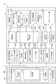
図1に示すように、電力変換システム1は、電力変換装置2とプログラミング支援装置3とを備える。電力変換装置2は、電力変換用の電力変換回路10と、電力変換回路10を制御する制御回路100とを有する。電力変換回路10は、整流回路11と、コンデンサ12と、インバータ回路13と、交流入力端子21と、交流出力端子22とを有する。整流回路11は、例えばダイオードブリッジ回路であり、交流入力端子21に入力された交流電力を直流化して直流母線14P,14Nに出力する。コンデンサ12は直流母線14P,14N間に接続されており、直流母線14P,14N間の直流電圧を平滑化する。インバータ回路13は、直流母線14P,14Nの直流電力を交流電力に変換して交流出力端子22に出力するための回路である。インバータ回路13は、例えばIGBT等の複数のスイッチ15を有する。当該複数のスイッチ15のオン・オフを切り替えることにより、直流電力を交流電力に変換することが可能である。
[Power conversion system]
As shown in FIG. 1, the power conversion system 1 includes a
なお、電力変換回路10は、出力電力を制御可能な回路である限りいかなる回路であってもよい。例えば電力変換回路10は、直流の入力電力を交流の出力電力に変換する回路であってもよく、交流の入力電力を直流の出力電力に変換する回路であってもよく、直流の入力電力を直流の出力電力に変換する回路であってもよい。また、電力変換回路10は、交流電力の直流化を行うことなく、交流の入力電力と交流の出力電力との間の電力変換を行うマトリクスコンバータ回路であってもよい。
The
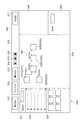
制御回路100は、スイッチ15のオン・オフ切り替えにより電力変換を実行するようにインバータ回路13を制御する。図2に示すように、制御回路100は、プログラム保持部111と、制御部112とを有する。プログラム保持部111は、電力変換回路10を制御するための制御プログラムを記憶している。例えばプログラム保持部111は、モジュール保持部113とシーケンス保持部114とを含む。
The
モジュール保持部113は、複数のプログラムモジュールを記憶する。プログラムモジュールは、例えば関数化された一つ又は複数の情報処理手順を含む実行形式のプログラムである。複数のプログラムモジュールの組み合わせの変更により、様々な制御プログラムを構成することが可能である。
The
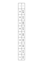
シーケンス保持部114は、シーケンスデータを記憶する。シーケンスデータは、制御プログラムを構成する複数のプログラムモジュールの実行順序を示すデータである。図3は、シーケンスデータを例示するテーブルである。図3の上側の行における各セルの数値は、実行順序を示している。図3の下側の行における各セルの数値は、プログラムモジュールのIDを示している。シーケンス保持部114は、シーケンスデータに加えて当該シーケンスデータを設定したユーザのIDを記憶するように構成されていてもよい。
The
図2に戻り、制御部112は、プログラム保持部111に記憶された制御プログラムに従って電力変換回路10を制御する。例えば制御部112は、プログラム保持部111に記憶された制御プログラムに従ってゲート駆動信号を生成し、電力変換回路10のスイッチ15に出力する。
Returning to FIG. 2, the
プログラミング支援装置3は、上述した制御プログラムの生成を支援する装置であり、有線又は無線により電力変換装置2との間で情報通信を行う。プログラミング支援装置3は、少なくとも、電力変換装置2から制御プログラムを読み出すことと、制御プログラムに基づいて、ブロック図の表示用データを生成することと、を実行するように構成されている。ブロック図は、複数のファンクションブロックと、ファンクションブロック間の情報の入出力を示すリンクとにより制御プログラムの内容を示す図である。表示用データを生成することは、電力変換装置2に記憶されたシーケンスデータと、ファンクションブロックとプログラムモジュールとの対応関係と、に基づいてブロック図の表示用データを生成することを含んでいてもよい。
The
プログラミング支援装置3は、ブロック図におけるファンクションブロックの配置と、リンクとに基づいて、シーケンスデータを生成することを更に実行するように構成されていてもよい。プログラミング支援装置3は、自装置が生成したシーケンスデータと、自装置に記憶されたユーザのIDとを対応付けて電力変換装置2に保存することと、電力変換装置2に記憶されたIDと、自装置に記憶されたIDとが一致しない場合には、当該電力変換装置2に記憶された制御プログラムに基づく表示用データの生成を禁止することとを更に実行するように構成されていてもよい。プログラミング支援装置3は、ブロック図における少なくとも一部のファンクションブロックに対し、仮想的な入力データを設定することと、電力変換装置2に記憶された複数のプログラムモジュールにそれぞれ対応する複数のプログラムモジュール(以下、「対応モジュール」という。)のいずれかを、シーケンスデータと仮想的な入力データとに従って実行することと、対応モジュールの実行結果をブロック図と共に表示するための上書用データを生成することと、を更に実行するように構成されていてもよい。
The
例えばプログラミング支援装置3は、表示データ保持部214と、ブロック保持部212と、シーケンスデータ取得部219と、表示データ生成部221と、画像表示部224とを有する。表示データ保持部214は、プログラミング支援画面(制御プログラムの生成支援用の画面)の表示用データを記憶する。
For example, the
図4は、プログラミング支援画面を例示する模式図である。図4に示すプログラミング支援画面300は、ツールバー310と、ブロック図表示部320と、ブロック選択部330と、プロパティ表示部340と、条件入力部350とを有する。ツールバー310は、複数のツールを表示する。複数のツールは、例えば読出ボタン311と、コンパイルボタン312と、書込ボタン313と、連続実行ボタン314と、ステップ実行ボタン315と、停止ボタン316と、ID追加ボタン317とを含む。読出ボタン311は、電力変換装置2からの制御プログラムの読み出しを指示するためのボタンである。コンパイルボタン312は、ブロック図に基づくシーケンスデータの生成を指示するためのボタンである。書込ボタン313は、シーケンスデータの電力変換装置2への書き込みを指示するためのボタンである。連続実行ボタン314は、連続モード(後述)でのシミュレーションの実行を指示するためのボタンである。ステップ実行ボタン315は、ステップモード(後述)でのシミュレーションの実行を指示するためのボタンである。停止ボタン316は、シミュレーションの停止を指示するためのボタンである。ID追加ボタン317は、ID保持部211へのユーザのIDの追加登録を指示するためのボタンである。
FIG. 4 is a schematic diagram illustrating a programming support screen. The
ブロック図表示部320は、ブロック図321を表示するためのエリアである。ブロック図321は、複数のファンクションブロック322と、ファンクションブロック322間の情報の入出力を示すリンク323とにより制御プログラムの内容を示す。ファンクションブロック322は、情報の取得と、取得した情報に基づく情報の出力とを行う。ファンクションブロック322は、情報の入力用のプログラムモジュールに対応付けられた入力端子324と、情報の出力用のプログラムモジュールに対応付けられた出力端子325と、の少なくとも一方を含んでいてもよい。例えば、複数のファンクションブロック322は、信号入力用のブロック322Aと、信号出力用のブロック322Bと、途中演算用のブロック322Cとを含む。
The block
信号入力用のブロック322Aは、信号を取得するためのブロックであり、出力端子325を有する。当該出力端子325は、取得した信号に基づく情報を他のファンクションブロック322に出力するためのプログラムモジュールに対応付けられている。取得対象の信号の具体例としては、電力変換装置2内外のセンサからの信号又は電力変換装置2外からの指令信号等が挙げられる。取得した信号に基づく情報は、取得した信号自体を示す数値情報であってもよいし、当該信号に所定の演算(例えばゲインの乗算)を施した数値情報であってもよい。
The
信号出力用のブロック322Bは、信号を出力するためのブロックであり、入力端子324を有する。当該入力端子324は、他のファンクションブロック322から出力された情報を取得するためのプログラムモジュールに対応付けられている。信号出力用のブロック322Bは、入力端子324が取得した情報に基づく信号を出力する。出力対象の信号の具体例としては、ゲート駆動信号を生成するための周波数指令信号等が挙げられる。取得した情報に基づく信号は、取得した情報自体を示す信号であってもよいし、当該情報に所定の演算(例えばゲインの乗算)を施した数値情報を示す信号であってもよい。
The
途中演算用のブロック322Cは、入力端子324及び出力端子325を有する。当該入力端子324は、他のファンクションブロック322から出力された情報を取得するためのプログラムモジュールに対応付けられている。当該出力端子325は、入力端子324が取得した情報に基づく情報を他のファンクションブロック322に出力するためのプログラムモジュールに対応付けられている。取得した情報に基づく情報は、取得した数値情報自体であってもよいし、当該数値情報に所定の演算(例えばゲインの乗算)を施した数値情報であってもよい。
The
ファンクションブロック322は、複数の入力端子324を含んでいてもよく、複数の出力端子325を含んでいてもよい。例えば途中演算用のブロック322Cは、複数の入力端子324と一つの出力端子325とを含んでいてもよく、当該出力端子325は、複数の入力端子324がそれぞれ取得した複数の情報に基づく情報を他のファンクションブロック322に出力するためのプログラムモジュールに対応付けられていてもよい。複数の情報に基づく情報の具体例としては、当該複数の情報を加算した情報等が挙げられる。
The
リンク323は、いずれかのファンクションブロック322の出力端子325と他のいずれかのファンクションブロック322の入力端子324とを接続し、当該出力端子325からの情報がファンクションブロック322に入力されることを示す。
The
ブロック選択部330は、ブロック図表示部320に追加するファンクションブロック322を選択するためのエリアである。例えばブロック選択部330は、キー入力ボックス331と、カテゴリリスト332と、ブロックリスト333とを含む。キー入力ボックス331は、ブロック保持部212から所望のファンクションブロック322を検索するためのキーを入力するテキストボックスである。カテゴリリスト332は、ファンクションブロック322のカテゴリを表示するリストである。ブロックリスト333は、カテゴリリスト332において選択されたカテゴリに属する全てのファンクションブロック322のうち、キー入力ボックス331に入力されたキーに該当するファンクションブロック322をアイコン表示するリストである。
The
プロパティ表示部340は、ブロック図表示部320において選択されたファンクションブロック322のプロパティを表示するエリアである。条件入力部350は、ブロック図表示部320において選択されたファンクションブロック322についてのシミュレーションの条件を入力するためのエリアである。シミュレーションの条件の具体例としては、例えば上述した信号入力用のブロック322Aに入力する信号を特定する条件等が挙げられる。当該条件は、当該信号の値を指定する数値指定であってもよいし、周期及び振幅を含む波形指定であってもよい。
The
図2に戻り、ブロック保持部212は、複数のファンクションブロック322を複数のプログラムモジュールのいずれかに対応付けて記憶する。例えばブロック保持部212は、ファンクションブロック322の入力端子324の識別情報と情報入力用のプログラムモジュールの識別情報とを対応付けて記憶し、ファンクションブロック322の出力端子325の識別情報と情報出力用のプログラムモジュールの識別情報とを対応付けて記憶する。
Returning to FIG. 2, the
シーケンスデータ取得部219は、電力変換装置2のシーケンス保持部114に記憶されたシーケンスデータを取得する。表示データ生成部221は、電力変換装置2のプログラム保持部111に記憶された制御プログラムに基づいて、ブロック図321の表示用データを生成し、表示データ保持部214に保存する。例えば表示データ生成部221は、シーケンスデータ取得部219により取得されたシーケンスデータと、ブロック保持部212におけるファンクションブロック322とプログラムモジュールとの対応関係と、に基づいてブロック図321の表示用データを生成する。表示データ生成部221は、いずれかのファンクションブロック322の出力端子325と他のいずれかのファンクションブロック322の入力端子324とをリンク323により接続するようにブロック図321の表示用データを生成してもよい。例えば表示データ生成部221は、より細分化された構成要素として、配置設定部222とリンクデータ生成部223とを有する。
The sequence
配置設定部222は、ファンクションブロック322の配置を設定する。リンクデータ生成部223は、リンク323の表示用データを生成する。例えば、シーケンスデータ取得部219が取得したシーケンスデータにおいて、いずれかのファンクションブロック322の出力端子325に対応付けられたプログラムモジュールの次に、他のいずれかのファンクションブロック322の入力端子324に対応付けられたプログラムモジュールが位置している場合に、配置設定部222は、当該いずれかのファンクションブロック322と、当該他のいずれかのファンクションブロック322とが第1の方向(例えば図4における左右方向)にずれるようにファンクションブロック322の配置を設定し、リンクデータ生成部223は、当該いずれかのファンクションブロック322の当該出力端子325と、当該他のいずれかのファンクションブロック322の当該入力端子324とを接続するようにリンク323の表示用データを生成する。なお、「第1の方向にずれる」とは、第1の方向における位置が互いに異なるように配置されることを意味し、第1の方向と直交する方向における配置関係は特定しない。
The
また、シーケンスデータ取得部219が取得したシーケンスデータにおいて、いずれかのファンクションブロック322の入力端子324又は出力端子325に対応付けられたプログラムモジュールの次に、他のいずれかのファンクションブロック322の出力端子325に対応付けられたプログラムモジュールが位置している場合に、配置設定部222は、当該いずれかのファンクションブロック322と、当該他のいずれかのファンクションブロック322とが第1の方向に交差する第2の方向(例えば図4における上下方向)にずれるようにファンクションブロック322の配置を設定する。
Further, in the sequence data acquired by the sequence
表示データ生成部221は、シーケンスデータにおける実行順序に沿った手順でブロック図321の表示用データを生成(すなわち図4の左側から順にブロック図321の表示用データを生成)してもよいし、シーケンスデータにおける実行順序を遡る手順でブロック図321の表示用データを生成(すなわち図4の右側から順にブロック図321の表示用データを生成)してもよい。
The display
画像表示部224は、表示データ保持部214に保存された表示用データに従って、ブロック図321を含むプログラミング支援画面300を表示する。
The
プログラミング支援装置3は、ID保持部211と、ID登録部216と、相手側ID取得部217と、セキュリティ管理部218とを更に有してもよい。ID保持部211は、自装置(当該ID保持部211を有するプログラミング支援装置3)のユーザのIDを記憶する。ID保持部211は、複数のユーザのIDを記憶し得るように構成されていてもよい。ID登録部216は、追加入力されたユーザのIDを取得してID保持部211に保存する。
The
例えばID登録部216は、上記ID追加ボタン317(図4参照)のクリックに応じて、ユーザのID及びパスワードの入力用のダイアログボックスを表示する。ユーザのID及びパスワードは、例えば電力変換装置2のメーカにより予め電力変換装置2に対して発行されており、当該メーカのサーバ等に登録されている。ユーザのID及びパスワードが入力されると、ID登録部216は当該IDの登録可否を判定し、登録可である場合に当該IDをID保持部211に保存する。例えばID登録部216は、入力されたID及びパスワードの組み合わせが上記サーバ等に登録されている場合には、当該IDを登録可と判定し、当該組み合わせが上記サーバ等に登録されていない場合には当該IDを登録不可と判定する。
For example, the
相手側ID取得部217は、電力変換装置2のシーケンス保持部114に記憶されたIDを取得する。
The other party
セキュリティ管理部218は、相手側ID取得部217により取得されたIDと、ID保持部211に記憶されたIDとが一致しない場合には、プログラム保持部111に記憶された制御プログラムに基づくブロック図321の表示用データの生成を禁止する。例えばセキュリティ管理部218は、シーケンスデータ取得部219によるシーケンスデータの取得を禁止する。セキュリティ管理部218は、相手側ID取得部217により取得されたIDと、ID保持部211に記憶された複数のIDのいずれか一つとが一致する場合に、プログラム保持部111に記憶された制御プログラムに基づくブロック図321の表示用データの生成を許可するように構成されていてもよい。
The
なお、セキュリティ管理部218は、電力変換装置2側に設けられていてもよい。この場合、セキュリティ管理部218は、シーケンス保持部114に記憶されたIDと、ID保持部211に記憶されたIDとが一致しない場合に、例えばシーケンス保持部114からシーケンスデータ取得部219へのシーケンスデータの送信を禁止する。
The
プログラミング支援装置3は、表示データ編集部232と、コンパイル部225と、シーケンス保持部215と、対応プログラム保持部213と、入力データ設定部226と、モード設定部227と、シミュレーション部228と、結果表示データ生成部229と、シーケンスデータ登録部231とを更に有してもよい。
The
表示データ編集部232は、プログラミング支援画面300への操作入力に従って、表示データ保持部214の表示用データを変更する。例えば表示データ編集部232は、ブロックリスト333からブロック図表示部320にファンクションブロック322がドラッグされた場合に、ドラッグ完了位置に従って当該ファンクションブロック322をブロック図321に追加するように表示用データを変更する。また、表示データ編集部232は、ブロック図表示部320においていずれかのファンクションブロック322の出力端子325から他のファンクションブロック322の入力端子324に至るドラッグ入力がなされた場合に、当該出力端子325と当該入力端子324とを接続するリンク323を追加するように表示用データを変更する。また、表示データ編集部232は、ブロック図表示部320においてファンクションブロック322又はリンク323を削除する入力がなされた場合に、当該ファンクションブロック322又はリンク323を削除するように表示用データを変更する。
The display
コンパイル部225は、ブロック図321におけるファンクションブロック322の配置と、リンク323とに基づいて、シーケンスデータを生成するコンパイル処理を行い、シーケンス保持部215に保存する。例えばコンパイル部225は、リンク323により接続された出力端子325及び入力端子324にそれぞれ対応付けられた二つのプログラムモジュールが順に並ぶようにシーケンスデータを生成する。ファンクションブロック322の配置及びリンク323は、例えば表示データ保持部214から取得される。コンパイル処理は、例えば、ブロック保持部212に記憶された、ファンクションブロック322とプログラムモジュールとの対応付けに基づいて行われる。なお、コンパイル部225が実行する「コンパイル処理」に対し、表示データ生成部221が実行する処理は「逆コンパイル処理」に相当する。
The
対応プログラム保持部213は、モジュール保持部113に記憶された複数のプログラムモジュールにそれぞれ対応する複数のプログラムモジュール(上記対応モジュール)を記憶する。対応モジュールは、プログラミング支援装置3におけるシミュレーション用のプログラムモジュールであり、例えばモジュール保持部113に記憶されたプログラムモジュールをプログラミング支援装置3にて仮想的に実行し得るように改変したものである。仮想的に実行とは、電力変換装置2を動作させることなく実行することを意味する。
The corresponding
入力データ設定部226は、ブロック図321における少なくとも一部のファンクションブロック322に対し、仮想的な入力データを設定する。例えば入力データ設定部226は、条件入力部350への入力内容に基づいて上記入力データを設定する。入力データ設定部226は、条件入力部350において周期及び振幅を含む波形指定が入力されている場合に、当該波形指定に基づいて波形の入力データを設定するように構成されていてもよい。
The input
モード設定部227は、シミュレーションの実行モードを、連続モードとステップモードとを含む複数のモードのいずれかに設定する。連続モードは、シーケンスデータに従った一連のプログラムモジュールの実行を繰り返す実行モードである。ステップモードは、一つ又は複数のプログラムモジュール(以下、「一セットのプログラムモジュール」という。)を実行する度にプログラムモジュールの実行を中断する実行モードである。例えばモード設定部227は、連続実行ボタン314がクリックされた場合には実行モードを連続モードに設定し、ステップ実行ボタン315がクリックされた場合には実行モードをステップモードに設定する。
The
ステップモードにおいて実行される上記一セットのプログラムモジュールの具体例としては、一制御周期分のプログラムモジュール(連続モードで繰り返される一連のプログラムモジュール)が挙げられる。すなわち、ステップモードは、一制御周期ごとにプログラムモジュールの実行を中断するように設定されていてもよい。上記一セットのプログラムモジュールは、一つのファンクションブロック322に対応付けられたプログラムモジュールであってもよい。すなわち、ステップモードは、一つのファンクションブロック322ごとにプログラムモジュールの実行を中断するように設定されていてもよい。なお、モード設定部227は、ユーザの指定に応じて一セットのプログラムモジュールをカスタマイズできるように構成されていてもよい。
Specific examples of the above-mentioned set of program modules executed in the step mode include a program module for one control cycle (a series of program modules repeated in the continuous mode). That is, the step mode may be set to interrupt the execution of the program module every one control cycle. The set of program modules may be a program module associated with one
シミュレーション部228は、モード設定部227により設定された実行モードでシミュレーションを実行する。具体的に、シミュレーション部228は、コンパイル部225により生成されたシーケンスデータと、入力データ設定部226により設定された仮想的な入力データとに従って、対応プログラム保持部213に記憶されたプログラムモジュールを実行する。
The
結果表示データ生成部229は、シミュレーション部228によるプログラムモジュールの実行結果をブロック図表示部320に表示するための上書用データを生成して表示データ保持部214に保存する。例えば結果表示データ生成部229は、プログラムモジュールの実行により算出された数値を当該プログラムモジュールに対応するファンクションブロック322の近傍に表示するように上書用データを生成する。
The result display
シーケンスデータ登録部231は、コンパイル部225によりシーケンス保持部215に保存されたシーケンスデータと、ID保持部211に記憶されたいずれかのIDとを対応付けて電力変換装置2のシーケンス保持部114に保存する。
The sequence
図5は、電力変換システム1のハードウェア構成を例示するブロック図である。図5に示すように、制御回路100は、プロセッサ191と、メモリ192と、ストレージ193と、ゲート駆動回路194と、通信ポート195とを有する。ストレージ193は、コンピュータによって読み取り可能な不揮発型の記憶媒体(例えばハードディスク又はフラッシュメモリ)である。ストレージ193は、制御部112を構成するためのプログラムの記憶領域と、上記モジュール保持部113及びシーケンス保持部114に割り当てられる記憶領域とを含む。メモリ192は、ストレージ193からロードしたプログラム及びプロセッサ191による演算結果等を一時的に記憶する。プロセッサ191は、メモリ192と協働して上記プログラムを実行することで制御部112として機能する。ゲート駆動回路194は、プロセッサ191からの指令に応じて、ゲート駆動信号をインバータ回路13に出力する。通信ポート195は、プロセッサ191からの指令に応じて、プログラミング支援装置3との間でデータの送受信を行う。
FIG. 5 is a block diagram illustrating a hardware configuration of the power conversion system 1. As shown in FIG. 5, the
プログラミング支援装置3は、プログラミング支援回路200を有する。プログラミング支援回路200は、プロセッサ291と、メモリ292と、ストレージ293と、モニタ294と、入力デバイス295と、通信ポート296と、ネットワークアダプタ297とを有する。ストレージ293は、コンピュータによって読み取り可能な不揮発型の記憶媒体(例えばハードディスク又はフラッシュメモリ)である。ストレージ293は、電力変換装置2から制御プログラムを読み出すことと、制御プログラムに基づいてブロック図321の表示用データを生成することと、を装置に実行させるためのプログラムを記憶している。
The
当該プログラムは、電力変換装置2に記憶されたシーケンスデータと、ファンクションブロック322とプログラムモジュールとの対応関係と、に基づいてブロック図321の表示用データをプログラミング支援装置3に生成させるように構成されていてもよい。
The program is configured to cause the
当該プログラムは、いずれかのファンクションブロック322の出力端子325と他のいずれかのファンクションブロック322の入力端子324とをリンク323により接続するようにブロック図321の表示用データをプログラミング支援装置3に生成させるように構成されていてもよい。
The program generates display data of block FIG. 321 in the
当該プログラムは、電力変換装置2に記憶されたシーケンスデータにおいて、いずれかのファンクションブロック322の出力端子325に対応付けられたプログラムモジュールの次に、他のいずれかのファンクションブロック322の入力端子324に対応付けられたプログラムモジュールが位置している場合に、当該いずれかのファンクションブロック322と、当該他のいずれかのファンクションブロック322とが第1の方向にずれるようにファンクションブロック322の配置をプログラミング支援装置3に設定させ、当該いずれかのファンクションブロック322の当該出力端子325と、当該他のファンクションブロック322の当該入力端子324とを接続するようにリンク323の表示用データをプログラミング支援装置3に生成させるように構成されていてもよい。
In the sequence data stored in the
当該プログラムは、電力変換装置2に記憶されたシーケンスデータにおいて、いずれかのファンクションブロック322の入力端子324又は出力端子325に対応付けられたプログラムモジュールの次に、他のいずれかのファンクションブロックの出力端子325に対応付けられたプログラムモジュールが位置している場合に、当該いずれかのファンクションブロック322と、当該他のいずれかのファンクションブロック322とが第1の方向に交差する第2の方向にずれるようにファンクションブロック322の配置をプログラミング支援装置3に設定させるように構成されていてもよい。
In the sequence data stored in the
当該プログラムは、ブロック図321におけるファンクションブロック322の配置と、リンク323とに基づいて、シーケンスデータを生成することを更にプログラミング支援装置3に実行させるように構成されていてもよい。
The program may be configured to cause the
当該プログラムは、自装置が生成したシーケンスデータと、自装置に記憶されたユーザのIDとを対応付けて電力変換装置2に保存することと、電力変換装置2に記憶されたIDと自装置に記憶されたIDとが一致しない場合には、電力変換装置2に記憶された制御プログラムに基づく表示用データの生成を禁止することと、を更にプログラミング支援装置3に実行させるように構成されていてもよい。
The program associates the sequence data generated by the own device with the user ID stored in the own device and stores it in the
当該プログラムは、複数のユーザのIDを自装置に保存し得るように構成されており、電力変換装置に記憶されたIDと、自装置に記憶されたいずれかのIDとが一致する場合に、電力変換装置2に記憶された制御プログラムに基づく表示用データの生成を許可するように構成されていてもよい。
The program is configured so that the IDs of a plurality of users can be stored in the own device, and when the ID stored in the power conversion device matches any of the IDs stored in the own device, It may be configured to allow the generation of display data based on the control program stored in the
当該プログラムは、ブロック図321における少なくとも一部のファンクションブロック322に対し、仮想的な入力データを設定することと、シーケンスデータと、仮想的な入力データとに従って上記対応モジュールのいずれかを実行することと、対応モジュールの実行結果をブロック図321と共に表示するための上書用データを生成することと、を更にプログラミング支援装置3に実行させるように構成されていてもよい。
The program sets virtual input data for at least a part of the function blocks 322 in the block diagram 321 and executes any of the above-mentioned corresponding modules according to the sequence data and the virtual input data. And, the overwriting data for displaying the execution result of the corresponding module together with the block diagram 321 may be generated, and the
当該プログラムは、周期及び振幅を含む波形指定に基づいて波形の入力データをプログラミング支援装置3に設定させるように構成されていてもよい。
The program may be configured to cause the
当該プログラムは、プログラミング支援装置3におけるシミュレーションの実行モードを、上記連続モードと上記ステップモードとを含む複数のモードのいずれかに設定することと、設定した実行モードで対応プログラムモジュールを実行することとをプログラミング支援装置3に実行させるように構成されていてもよい。
The program sets the execution mode of the simulation in the
一例として、ストレージ293は、図2に示したプログラミング支援装置3の複数の要素のうち、ID保持部211、ブロック保持部212、対応プログラム保持部213、表示データ保持部214、及びシーケンス保持部215に割り当てられる記憶領域と、他の要素を構成するためのプログラムの記憶領域とを含む。
As an example, the
モニタ294は、例えば液晶モニタ等の画像表示装置であり、例えば上記画像表示部224として用いられる。入力デバイス295は、例えばキーパッド等の情報入力装置であり、モニタ294に表示されるプログラミング支援画面300への操作入力等に用いられる。モニタ294及び入力デバイス295は、所謂タッチパネルのように一体化されていてもよい。通信ポート296は、プロセッサ291からの指令に応じて、電力変換装置2の通信ポート195との間でデータの送受信を行う。ネットワークアダプタ297は、インターネット等のネットワーク回線NWを介して電力変換装置2のメーカのサーバ4等に接続されており、プロセッサ291からの指令に応じてサーバ4との間でデータの送受信を行う。ネットワークアダプタ297は、ID登録部216によるIDの登録可否の判定等に用いられる。なお、通信ポート296と通信ポート195との間にネットワーク回線NWが介在していてもよい。
The
〔プログラミング支援手順〕
続いて、プログラミング支援方法の一例として、プログラミング支援装置3が実行するプログラミング支援手順を説明する。当該手順は、電力変換装置2に記憶された制御プログラムに基づいてブロック図321の表示用データを生成する手順(逆コンパイル処理手順)と、ブロック図321におけるファンクションブロック322の配置とリンク323とに基づいてシーケンスデータを生成する手順(コンパイル処理手順)と、コンパイル処理手順で生成されたシーケンスデータのシミュレーションを行う手順(シミュレーション手順)と、コンパイル処理手順で生成されたシーケンスデータを電力変換装置2に保存する手順(シーケンス登録手順)と、を含む。以下、各手順の内容を詳細に例示する。
[Programming support procedure]
Subsequently, as an example of the programming support method, the programming support procedure executed by the
(逆コンパイル処理手順)
図6に示すように、プログラミング支援装置3は、まずステップS01,S02を順に実行する。ステップS01では、相手側ID取得部217が、電力変換装置2のシーケンス保持部114に記憶されたIDを取得する。ステップS02では、セキュリティ管理部218が、相手側ID取得部217により取得されたIDと、ID保持部211に記憶された複数のIDのいずれか一つとが一致するか否かを確認する。ステップS02において、相手側ID取得部217により取得されたIDがID保持部211に記憶された複数のIDのいずれとも一致しないと判定した場合、セキュリティ管理部218はシーケンスデータ取得部219によるシーケンスデータの取得を禁止する。これにより、プログラミング支援装置3は、ステップS03〜S09を実行することなく逆コンパイル処理を中止する。
(Decompilation procedure)
As shown in FIG. 6, the
ステップS02において、相手側ID取得部217により取得されたIDとID保持部211に記憶された複数のIDのいずれか一つとが一致すると判定した場合、プログラミング支援装置3はステップS03を実行する。ステップS03では、シーケンスデータ取得部219が、電力変換装置2のシーケンス保持部114に記憶されたシーケンスデータを取得する。
In step S02, when it is determined that the ID acquired by the other party
次に、プログラミング支援装置3は、ステップS04を実行する。ステップS04では、表示データ生成部221が、ステップS03において取得されたシーケンスデータから、最初のプログラムモジュールを選択する。
Next, the
次に、プログラミング支援装置3は、ステップS05,S06,S07を順に実行する。ステップS05では、ステップS04において選択されたプログラムモジュールがいずれのファンクションブロック322に対応付けられているかを表示データ生成部221が特定する。例えば表示データ生成部221は、ブロック保持部212を参照して、当該プログラムモジュールがいずれのファンクションブロック322のいずれの端子(入力端子324又は出力端子325)に対応付けられているかを特定する。ステップS06では、表示データ生成部221が、ステップS03において取得されたシーケンスデータと、ステップS05において特定されたファンクションブロック322とプログラムモジュールとの対応関係と、に基づいてブロック図321の表示用データを更新し、表示データ保持部214に保存する。ステップS06の具体的な処理内容については後述する。ステップS07では、表示データ生成部221が、制御プログラム全体の表示用データの生成が完了したか否かを確認する。例えば表示データ生成部221は、ステップS05,S06の実行対象として選択されていないプログラムモジュールがシーケンスデータに残っているか否かを確認する。
Next, the
ステップS07において、制御プログラム全体の表示用データの生成は完了していないと判定した場合、プログラミング支援装置3はステップS08を実行する。ステップS08では、表示データ生成部221が一つ後(シーケンスデータにおける一つ後)のプログラムモジュールを選択する。その後、プログラミング支援装置3は処理をステップS05に戻す。以後、プログラミング支援装置3は、制御プログラム全体の表示用データの生成が完了するまで、プログラムモジュールの選択とブロック図321の表示用データの更新とを繰り返す。
If it is determined in step S07 that the generation of display data for the entire control program has not been completed, the
ステップS07において、制御プログラム全体の表示用データの生成が完了したと判定した場合、プログラミング支援装置3はステップS09を実行する。ステップS09では、画像表示部224が、ステップS05,S06,S07,S08の繰り返しにより生成された表示用データに基づくブロック図321をプログラミング支援画面300に表示する。以上で逆コンパイル処理手順が完了する。
If it is determined in step S07 that the generation of display data for the entire control program has been completed, the
図7は、ステップS06における表示用データの更新手順を示すフローチャートである。図7に示すように、プログラミング支援装置3は、まずステップS11を実行する。ステップS11では、配置設定部222が、ブロック図321へのファンクションブロック322の追加の要否を確認する。具体的に、配置設定部222は、選択中のプログラムモジュールに対応付けられたファンクションブロック322がブロック図321の表示用データに存在している場合には、当該ファンクションブロック322の追加を不要と判定し、当該ファンクションブロック322がブロック図321の表示用データに存在していない場合には、当該ファンクションブロック322の追加を必要と判定する。
FIG. 7 is a flowchart showing the procedure for updating the display data in step S06. As shown in FIG. 7, the
ステップS11において、当該ファンクションブロック322の追加は不要であると判定した場合、プログラミング支援装置3は表示用データの更新手順を完了する。ステップS11において、当該ファンクションブロック322の追加は必要であると判定した場合、プログラミング支援装置3はステップS12を実行する。ステップS12では、追加対象のファンクションブロック322の他のファンクションブロック322がブロック図321の表示用データに存在しているか否かを配置設定部222が確認する。
If it is determined in step S11 that the addition of the
ステップS12において、他のファンクションブロック322は存在していないと判定した場合、プログラミング支援装置3はステップS13を実行する。ステップS13では、配置設定部222が、追加対象のファンクションブロック322をブロック図321の表示用データに追加する。
If it is determined in step S12 that the
ステップS12において、他のファンクションブロック322が存在していると判定した場合、プログラミング支援装置3はステップS14を実行する。ステップS14では、追加対象のファンクションブロック322と、他のファンクションブロック322との間に情報の出入力関係があるか否かを配置設定部222が確認する。例えば、選択中のプログラムモジュールが追加対象のファンクションブロック322の入力端子324に対応付けられており、当該プログラムモジュールの一つ前(シーケンスデータにおける一つ前)のプログラムモジュールが他のファンクションブロック322の出力端子325に対応付けられている場合に、配置設定部222は上記出入力関係があると判定する。選択中のプログラムモジュールが追加対象のファンクションブロック322の出力端子325に対応付けられている場合、配置設定部222は上記出入力関係がないと判定する。
If it is determined in step S12 that another
ステップS14において、上記出入力関係がないと判定した場合、プログラミング支援装置3はステップS15を実行する。ステップS15では、配置設定部222が、上記一つ前のプログラムモジュールに対応付けられたファンクションブロック322に対して第2の方向にずれる配置にて、追加対象のファンクションブロック322を表示用データに追加する。
If it is determined in step S14 that there is no input / output relationship, the
ステップS14において、上記出入力関係があると判定した場合、プログラミング支援装置3はステップS16,S17を順に実行する。ステップS16では、表示データ生成部221が、上記一つ前のプログラムモジュールに対応付けられたファンクションブロック322に対して第1の方向にずれる配置にて、追加対象のファンクションブロック322を表示用データに追加する。ステップS17では、上記一つ前のプログラムモジュールに対応付けられた出力端子325と、選択中のプログラムモジュールに対応付けられた入力端子324とを接続するリンク323の表示用データをリンクデータ生成部223が追加する。以上で表示用データの更新手順が完了する。
If it is determined in step S14 that there is an input / output relationship, the
なお、ステップS04では、最初のプログラムモジュールに代えて最後のプログラムモジュールを選択してもよい。この場合、ステップS08では、一つ後のプログラムモジュールに代えて一つ前(シーケンスデータにおける一つ前)のプログラムモジュールを選択する。ステップS14では、選択中のプログラムモジュールが追加対象のファンクションブロック322の出力端子325に対応付けられており、当該プログラムモジュールの一つ後(シーケンスデータにおける一つ後)のプログラムモジュールが他のファンクションブロック322の入力端子324に対応付けられている場合に、配置設定部222は上記出入力関係があると判定する。選択中のプログラムモジュールが追加対象のファンクションブロック322の入力端子324に対応付けられている場合、配置設定部222は上記出入力関係がないと判定する。
In step S04, the last program module may be selected instead of the first program module. In this case, in step S08, the previous program module (one previous program in the sequence data) is selected instead of the next program module. In step S14, the selected program module is associated with the
(コンパイル処理手順)
図8に示すように、プログラミング支援装置3は、まずステップS21を実行する。ステップS21では、表示データ編集部232が、プログラミング支援画面300に対して、ブロック図321の表示を変更させる操作入力(以下、「編集入力」という。)がなされたか否かを確認する。
(Compilation procedure)
As shown in FIG. 8, the
ステップS21において、編集入力がなされたと判定した場合、プログラミング支援装置3はステップS22,S23を順に実行する。ステップS22では、表示データ編集部232が、編集入力に従ってブロック図321の表示用データを更新して表示データ保持部214に保存する。ステップS23では、画像表示部224が、表示データ保持部214に保存された表示用データに基づくブロック図321をプログラミング支援画面300に表示する。
If it is determined in step S21 that the edit input has been made, the
次に、プログラミング支援装置3はステップS24を実行する。ステップS21において、編集入力はなされていないと判定した場合、プログラミング支援装置3は、ステップS22,S23を実行することなくステップS24を実行する。ステップS24では、コンパイルの実行指令(例えばコンパイルボタン312のクリック)の有無をコンパイル部225が確認する。ステップS24において、コンパイルの実行指令はないと判定した場合、プログラミング支援装置3は処理をステップS21に戻す。以後、コンパイルの実行指令があると判定されるまで、プログラミング支援画面300への操作入力に従ったブロック図321の表示の更新が繰り返される。
Next, the
ステップS24において、コンパイルの実行指令があると判定した場合、プログラミング支援装置3はステップS25を実行する。ステップS25では、コンパイル部225が、ブロック図321におけるファンクションブロック322の配置と、リンク323とに基づいて、シーケンスデータを生成してシーケンス保持部215に保存する。例えばコンパイル部225は、リンク323により接続された出力端子325及び入力端子324にそれぞれ対応付けられた二つのプログラムモジュールが順に並ぶようにシーケンスデータを生成する。以上でコンパイル処理手順が完了する。
If it is determined in step S24 that there is a compile execution command, the
(シミュレーション手順)
図9に示すように、プログラミング支援装置3は、まずステップS31を実行する。ステップS31では、条件入力部350への入力(以下、「条件入力」という。)がなされたか否かを表示データ編集部232が確認する。ステップS31において、条件入力がなされたと判定した場合、プログラミング支援装置3はステップS32を実行する。ステップS32では、表示データ編集部232が、条件入力に従って条件入力部350の表示用データを更新して表示データ保持部214に保存する。ステップS33では、画像表示部224が、表示データ保持部214に保存された表示用データに基づいて条件入力部350の表示を更新する。
(Simulation procedure)
As shown in FIG. 9, the
次に、プログラミング支援装置3はステップS34を実行する。ステップS31において、条件入力はなされていないと判定した場合、プログラミング支援装置3は、ステップS32,S33を実行することなくステップS34を実行する。ステップS34では、シミュレーションの開始指令(例えば連続実行ボタン314又はステップ実行ボタン315のクリック)の有無をモード設定部227が確認する。ステップS34において、シミュレーションの開始指令はないと判定した場合、プログラミング支援装置3は処理をステップS31に戻す。以後、シミュレーションの開始指令があると判定されるまで、条件入力に従った条件入力部350の表示の更新が繰り返される。
Next, the
ステップS34において、シミュレーションの開始指令が有ると判定した場合、プログラミング支援装置3はステップS35,S36を順に実行する。ステップS35では、入力データ設定部226が、条件入力部350への入力内容に基づいて上記入力データを設定する。ステップS36では、モード設定部227が、シミュレーションの実行モードを、上記連続モードと上記ステップモードとを含む複数のモードのいずれかに設定する。例えばモード設定部227は、シミュレーションの開始指令のために連続実行ボタン314がクリックされた場合には実行モードを連続モードに設定し、シミュレーションの開始指令のためにステップ実行ボタン315がクリックされた場合には実行モードをステップモードに設定する。
If it is determined in step S34 that there is a simulation start command, the
次に、プログラミング支援装置3はステップS37,S38,S39,S41を順に実行する。ステップS37では、シミュレーション部228が、シーケンス保持部215に記憶されたシーケンスデータに従って、対応プログラム保持部213から実行対象のプログラムモジュールを選択する。ステップS38では、シミュレーション部228が、ステップS37において選択したプログラムモジュールを実行する。ステップS39では、結果表示データ生成部229が、シミュレーション部228によるプログラムモジュールの実行結果をブロック図321と共に(例えばブロック図321内に)表示するための上書用データを生成して表示データ保持部214に保存する。ステップS41では、画像表示部224が、表示データ保持部214に保存された表示用データに基づいてブロック図表示部320の表示を更新する。これにより、プログラムモジュールの実行結果を示す結果データ361がブロック図表示部320に表示される(図10参照)。
Next, the
次に、プログラミング支援装置3はステップS42を実行する。ステップS42では、実行モードが連続モードであるか否かをシミュレーション部228が確認する。ステップS42において、実行モードはステップモードであると判定した場合、プログラミング支援装置3はステップS43を実行する。ステップS43では、上記一セットのプログラムモジュールの実行が完了したか否かをシミュレーション部228が確認する。ステップS43において、上記一セットのプログラムモジュールの実行は完了していないと判定した場合、プログラミング支援装置3は処理をステップS37に戻す。以後、上記一セットのプログラムモジュールの実行が完了するまでは、シーケンスデータに従ったプログラムモジュールの選択と実行が繰り返される。
Next, the
ステップS43において、上記一セットのプログラムモジュールの実行が完了したと判定した場合、プログラミング支援装置3はステップS44を実行する。ステップS44では、シミュレーション部228がプログラムモジュールの実行を中断する。その後、プログラミング支援装置3は処理をステップS31に戻す。
When it is determined in step S43 that the execution of the set of program modules is completed, the
ステップS42において、実行モードは連続モードであると判定した場合、プログラミング支援装置3はステップS45を実行する。ステップS45では、シミュレーションの停止指令(例えば停止ボタン316のクリック)の有無をシミュレーション部228が確認する。ステップS45において、シミュレーションの停止指令はないと判定した場合、プログラミング支援装置3は処理をステップS37に戻す。以後、シミュレーションの停止指令があると判定されるまでは、シーケンスデータに従ったプログラムモジュールの選択と実行が繰り返される。ステップS45において、シミュレーションの停止指令があると判定した場合、プログラミング支援装置3は処理を中止する。以上でシミュレーション手順が完了する。
If it is determined in step S42 that the execution mode is the continuous mode, the
(シーケンス登録手順)
図11に示すように、プログラミング支援装置3は、ステップS51,S52,S53を順に実行する。ステップS51では、シーケンス保持部114に保存すべきシーケンスデータがシーケンス保持部215に記憶されるのをシーケンスデータ登録部231が待機する。ステップS52では、シーケンスデータの登録指令(例えば書込ボタン313のクリック)をシーケンスデータ登録部231が待機する。ステップS53では、シーケンスデータ登録部231が、コンパイル部225によりシーケンス保持部215に保存されたシーケンスデータと、ID保持部211に記憶されたいずれかのIDとを対応付けて電力変換装置2のシーケンス保持部114に保存する。以上でシーケンス登録手順が完了する。
(Sequence registration procedure)
As shown in FIG. 11, the
〔本実施形態の効果〕
以上に説明したように、電力変換システム1は、電力変換回路10と、電力変換回路10を制御するための制御プログラムを記憶したプログラム保持部111と、制御プログラムに従って電力変換回路10を制御する制御部112と、を有する電力変換装置2と、電力変換装置2に接続されるプログラミング支援装置3と、を備え、プログラミング支援装置3は、プログラム保持部111に記憶された制御プログラムに基づいて、複数のファンクションブロック322と、ファンクションブロック322間の情報の入出力を示すリンク323とにより制御プログラムの内容を示すブロック図321の表示用データを生成する表示データ生成部221を有する。
[Effect of this embodiment]
As described above, the power conversion system 1 includes a
この電力変換システム1によれば、電力変換装置2に記憶されている制御プログラムの内容を、プログラミング支援装置3によってファンクションブロック322間の情報の流れとしてわかり易く表示できる。したがって、制御プログラムを編集する作業の負担軽減に有効である。
According to the power conversion system 1, the contents of the control program stored in the
プログラム保持部111は、複数のプログラムモジュールを記憶するモジュール保持部113と、複数のプログラムモジュールの実行順序を示すシーケンスデータを記憶するシーケンス保持部114と、を含み、プログラミング支援装置3は、複数のファンクションブロック322を複数のプログラムモジュールのいずれかに対応付けて記憶するブロック保持部212を更に有し、表示データ生成部221は、シーケンス保持部215に記憶されたシーケンスデータと、ブロック保持部212におけるファンクションブロック322とプログラムモジュールとの対応関係と、に基づいてブロック図321の表示用データを生成してもよい。この場合、電力変換装置2側に記憶すべき情報量の増加を抑制しつつ、ファンクションブロック322間の情報の流れの表示用データを生成できる。
The
ファンクションブロック322は、情報の入力用のプログラムモジュールに対応付けられた入力端子324と、情報の出力用のプログラムモジュールに対応付けられた出力端子325と、の少なくとも一方を含み、表示データ生成部221は、いずれかのファンクションブロック322の出力端子325と他のいずれかのファンクションブロック322の入力端子324とをリンク323により接続するようにブロック図321の表示用データを生成してもよい。この場合、ファンクションブロック322の端子(入力端子324又は出力端子325)とプログラムモジュールとの対応関係に基づいて、リンク323の表示用データを容易に生成できる。
The
表示データ生成部221は、ファンクションブロック322の配置を設定する配置設定部222と、リンクの表示用データを生成するリンクデータ生成部223と、を含み、シーケンス保持部215に記憶されたシーケンスデータにおいて、いずれかのファンクションブロック322の出力端子325に対応付けられたプログラムモジュールの次に、他のいずれかのファンクションブロック322の入力端子324に対応付けられたプログラムモジュールが位置している場合に、配置設定部222は、当該いずれかのファンクションブロック322と、当該他のいずれかのファンクションブロック322とが第1の方向にずれるようにファンクションブロック322の配置を設定し、リンクデータ生成部223は、当該いずれかのファンクションブロック322の当該出力端子325と、当該他のいずれかのファンクションブロック322の当該入力端子324とを接続するようにリンク323の表示用データを生成してもよい。この場合、情報の流れに沿ってファンクションブロック322を並べることで、制御プログラムの内容をより把握し易くすることができる。
The display
シーケンス保持部215に記憶されたシーケンスデータにおいて、いずれかのファンクションブロック322の入力端子324又は出力端子325に対応付けられたプログラムモジュールの次に、他のいずれかのファンクションブロック322の出力端子325に対応付けられたプログラムモジュールが位置している場合に、配置設定部は、当該いずれかのファンクションブロック322と、当該他のいずれかのファンクションブロック322とが第1の方向に交差する第2の方向にずれるようにファンクションブロック322の配置を設定してもよい。この場合、複数の情報の流れを並行して表示することで、制御プログラムの内容をより把握し易くすることができる。
In the sequence data stored in the
プログラミング支援装置3は、ブロック図321におけるファンクションブロック322の配置と、リンク323とに基づいて、シーケンスデータを生成するコンパイル部225を更に備えていてもよい。この場合、ブロック図321上における制御プログラムの編集結果を容易にシーケンスデータに反映させることができる。
The
シーケンス保持部215は、シーケンスデータに加えて当該シーケンスデータを生成したユーザのIDを記憶するように構成されており、プログラミング支援装置3は、自装置のユーザのIDを記憶するID保持部211と、コンパイル部225により生成されたシーケンスデータと、ID保持部211に記憶されたいずれかのIDとを対応付けてシーケンス保持部215に保存するシーケンスデータ登録部231と、を更に有し、プログラミング支援装置3及び電力変換装置2の少なくとも一方は、シーケンス保持部215に記憶されたIDと、ID保持部211に記憶されたIDとが一致しない場合には、プログラム保持部111に記憶された制御プログラムに基づく表示用データの生成を禁止するセキュリティ管理部218を更に有していてもよい。この場合、電力変換装置2内の情報を高い信頼性で保護することができる。
The
ID保持部211は、複数のユーザのIDを記憶し得るように構成されており、セキュリティ管理部218は、プログラミング支援装置3に設けられており、シーケンス保持部114に記憶されたIDと、ID保持部211に記憶されたいずれかのIDとが一致する場合に、プログラム保持部111に記憶された制御プログラムに基づく表示用データの生成を許可するように構成されていてもよい。この場合、一台のプログラミング支援装置3にて複数台の電力変換装置2の制御プログラムを編集することができる。
The
プログラミング支援装置3は、ブロック図321における少なくとも一部のファンクションブロック322に対し、仮想的な入力データを設定する入力データ設定部226と、モジュール保持部113に記憶された複数のプログラムモジュールにそれぞれ対応する複数のプログラムモジュールを記憶する対応プログラム保持部213と、コンパイル部225により生成されたシーケンスデータと、入力データ設定部226により設定された仮想的な入力データとに従って、対応プログラム保持部213に記憶されたプログラムモジュールを実行するシミュレーション部228と、シミュレーション部228によるプログラムモジュールの実行結果をブロック図321と共に表示するための上書用データを生成する結果表示データ生成部229と、を更に備えていてもよい。この場合、電力変換装置2を動作させることなく、新たな制御プログラムを検証することができる。
The
入力データ設定部226は、周期及び振幅を含む波形指定に基づいて波形の入力データを設定するように構成されていてもよい。この場合、波形の入力データを設定可能にすることで、より多様な条件にて新たな制御プログラムを検証することができる。
The input
プログラミング支援装置3は、シミュレーションの実行モードを、シーケンスデータに従った一連のプログラムモジュールの実行を繰り返す連続モードと、一つ又は複数のプログラムモジュールを実行する度にプログラムモジュールの実行を中断するステップモードと、を含む複数のモードのいずれかに設定するモード設定部227を更に備え、シミュレーション部228は、対応プログラム保持部213に記憶されたプログラムモジュールを、モード設定部227により設定された実行モードで実行してもよい。この場合、ステップモードでのシミュレーションを可能にすることで、新たな制御プログラムをより詳細に検証することができる。
The
以上、実施形態について説明したが、本発明は必ずしも上述した形態に限定されるものではなく、その要旨を逸脱しない範囲で様々な変形が可能である。 Although the embodiments have been described above, the present invention is not necessarily limited to the above-described embodiments, and various modifications can be made without departing from the gist thereof.
1…電力変換システム、2…電力変換装置、3…プログラミング支援装置、10…電力変換回路、111…プログラム保持部、112…制御部、113…モジュール保持部、114…シーケンス保持部、211…ID保持部、212…ブロック保持部、213…対応プログラム保持部、215…シーケンス保持部、218…セキュリティ管理部、221…表示データ生成部、222…配置設定部、223…リンクデータ生成部、225…コンパイル部、226…入力データ設定部、227…モード設定部、228…シミュレーション部、229…結果表示データ生成部、231…シーケンスデータ登録部、321…ブロック図、322…ファンクションブロック、323…リンク、324…入力端子、325…出力端子。 1 ... Power conversion system, 2 ... Power conversion device, 3 ... Programming support device, 10 ... Power conversion circuit, 111 ... Program holding unit, 112 ... Control unit, 113 ... Module holding unit, 114 ... Sequence holding unit, 211 ... ID Holding unit, 212 ... Block holding unit, 213 ... Corresponding program holding unit, 215 ... Sequence holding unit, 218 ... Security management unit, 221 ... Display data generation unit, 222 ... Arrangement setting unit, 223 ... Link data generation unit, 225 ... Compile unit, 226 ... Input data setting unit, 227 ... Mode setting unit, 228 ... Simulation unit, 229 ... Result display data generation unit, 231 ... Sequence data registration unit, 321 ... Block diagram, 322 ... Function block, 323 ... Link, 324 ... Input terminal, 325 ... Output terminal.
Claims (11)
前記電力変換装置に接続されるプログラミング支援装置と、を備え、
前記プログラム保持部は、
複数のプログラムモジュールを記憶するモジュール保持部と、
前記複数のプログラムモジュールの実行順序を示すシーケンスデータを記憶するシーケンス保持部と、を含み、
前記プログラミング支援装置は、
前記複数のプログラムモジュールに対応付けられた複数のファンクションブロックを記憶するブロック保持部と、
2つ以上のファンクションブロックと少なくとも1つのリンクとにより前記制御プログラムの内容を示すブロック図の表示用データを生成する表示データ生成部と、を有し、
前記複数のファンクションブロックのそれぞれは、入力端子及び出力端子の少なくとも一方を有し、前記複数のファンクションブロックは、入力端子及び出力端子の両方を有する途中演算用のブロックを含み、
前記ブロック保持部は、前記複数のプログラムモジュールのうち情報入力用であるプログラムモジュールのそれぞれを前記複数のファンクションブロックのいずれかの入力端子に対応付け、前記複数のプログラムモジュールのうち情報出力用であるプログラムモジュールのそれぞれを前記複数のファンクションブロックのいずれかの出力端子に対応付け、前記途中演算用のブロックを情報入力用のプログラムモジュールと情報出力用のプログラムモジュールとに対応付け、
前記表示データ生成部は、
前記シーケンス保持部に記憶された前記シーケンスデータにおいて、第1ファンクションブロックの出力端子に対応付けられた情報出力用のプログラムモジュールの次に、第2ファンクションブロックの入力端子に対応付けられた情報入力用のプログラムモジュールが位置している場合に、前記第1ファンクションブロックと前記第2ファンクションブロックとが第1の方向にずれ、前記第1ファンクションブロックの前記出力端子と、前記第2ファンクションブロックの前記入力端子とがリンクで接続されるように前記表示用データを生成し、
前記シーケンス保持部に記憶された前記シーケンスデータにおいて、前記第1ファンクションブロックの入力端子に対応付けられた情報入力用のプログラムモジュール又は前記第1ファンクションブロックの出力端子に対応付けられた情報出力用のプログラムモジュールの次に、前記第2ファンクションブロックの出力端子に対応付けられた情報出力用のプログラムモジュールが位置している場合に、前記第1ファンクションブロックと前記第2ファンクションブロックとが前記第1の方向に交差する第2の方向にずれるように前記表示用データを生成する、電力変換システム。 A power conversion device having a power conversion circuit, a program holding unit that stores a control program for controlling the power conversion circuit, and a control unit that controls the power conversion circuit according to the control program.
A programming support device connected to the power conversion device is provided.
The program holding unit is
A module holder that stores multiple program modules and
A sequence holding unit for storing sequence data indicating the execution order of the plurality of program modules is included.
The programming support device is
A block holding unit that stores a plurality of function blocks associated with the plurality of program modules , and
It has a display data generation unit that generates display data of a block diagram showing the contents of the control program by using two or more function blocks and at least one link.
Each of the plurality of function blocks has at least one of an input terminal and an output terminal, and the plurality of function blocks include a block for intermediate calculation having both an input terminal and an output terminal.
The block holding unit associates each of the program modules for information input among the plurality of program modules with the input terminals of any of the plurality of function blocks, and is for information output among the plurality of program modules. Each of the program modules is associated with one of the output terminals of the plurality of function blocks, and the block for intermediate calculation is associated with the program module for information input and the program module for information output.
The display data generation unit
Information in the sequence data stored in the sequence retention unit, next to the program module for the associated information output to the output terminal of the first function block, associated to the input terminal of the second function block When the input program module is located, the first function block and the second function block are displaced in the first direction, and the output terminal of the first function block and the second function block The display data is generated so that the input terminal is connected by a link, and the display data is generated.
In the sequence data stored in the sequence retention unit, the first information is associated with the output terminal of the program module or the first function block of information associated with the input terminal input of the function block output following the program module, when a program module for output information output associated with the terminal of the second function block is located, the first function block and said second function block is the first A power conversion system that generates the display data so as to shift in a second direction that intersects in one direction.
前記ブロック図における前記ファンクションブロックの配置と、前記リンクとに基づいて、前記シーケンスデータを生成するコンパイル部を更に備える、請求項1記載の電力変換システム。 The programming support device is
The power conversion system according to claim 1, further comprising a compilation unit that generates the sequence data based on the arrangement of the function blocks in the block diagram and the links.
前記プログラミング支援装置は、自装置のユーザのIDを記憶するID保持部と、
前記コンパイル部により生成された前記シーケンスデータと、前記ID保持部に記憶されたいずれかのIDとを対応付けて前記シーケンス保持部に保存するシーケンスデータ登録部と、を更に有し、
前記プログラミング支援装置及び前記電力変換装置の少なくとも一方は、
前記シーケンス保持部に記憶されたIDと、前記ID保持部に記憶されたIDとが一致しない場合には、前記プログラム保持部に記憶された前記制御プログラムに基づく前記表示用データの生成を禁止するセキュリティ管理部を更に有する、請求項2記載の電力変換システム。 The sequence holding unit is configured to store the ID of the user who generated the sequence data in addition to the sequence data.
The programming support device includes an ID holding unit that stores the user's ID of the own device and
It further has a sequence data registration unit that associates the sequence data generated by the compilation unit with any ID stored in the ID holding unit and stores it in the sequence holding unit.
At least one of the programming support device and the power conversion device
When the ID stored in the sequence holding unit and the ID stored in the ID holding unit do not match, the generation of the display data based on the control program stored in the program holding unit is prohibited. The power conversion system according to claim 2, further comprising a security management unit.
前記セキュリティ管理部は、前記プログラミング支援装置に設けられており、前記シーケンス保持部に記憶されたIDと、前記ID保持部に記憶されたいずれかのIDとが一致する場合に、前記プログラム保持部に記憶された前記制御プログラムに基づく前記表示用データの生成を許可するように構成されている、請求項3記載の電力変換システム。 The ID holding unit is configured to be able to store the IDs of a plurality of the users.
The security management unit is provided in the programming support device, and when the ID stored in the sequence holding unit matches any ID stored in the ID holding unit, the program holding unit The power conversion system according to claim 3, wherein the display data is generated based on the control program stored in the control program.
前記ブロック図における少なくとも一部の前記ファンクションブロックに対し、仮想的な入力データを設定する入力データ設定部と、
前記モジュール保持部に記憶された前記複数のプログラムモジュールにそれぞれ対応する複数のプログラムモジュールを記憶する対応プログラム保持部と、
前記コンパイル部により生成された前記シーケンスデータと、前記入力データ設定部により設定された前記仮想的な入力データとに従って、前記対応プログラム保持部に記憶された前記プログラムモジュールを実行するシミュレーション部と、
前記シミュレーション部による前記プログラムモジュールの実行結果を前記ブロック図と共に表示するための上書用データを生成する結果表示データ生成部と、を更に備える、請求項2〜4のいずれか一項記載の電力変換システム。 The programming support device is
An input data setting unit that sets virtual input data for at least a part of the function blocks in the block diagram,
A corresponding program holding unit that stores a plurality of program modules corresponding to the plurality of program modules stored in the module holding unit, and a corresponding program holding unit that stores a plurality of program modules stored in the module holding unit.
A simulation unit that executes the program module stored in the corresponding program holding unit according to the sequence data generated by the compilation unit and the virtual input data set by the input data setting unit.
The power according to any one of claims 2 to 4, further comprising a result display data generation unit for generating overwriting data for displaying the execution result of the program module by the simulation unit together with the block diagram. Conversion system.
前記シミュレーション部は、前記対応プログラム保持部に記憶された前記プログラムモジュールを、前記モード設定部により設定された前記実行モードで実行する、請求項5又は6記載の電力変換システム。 The programming support device sets the execution mode of the simulation to a continuous mode in which the execution of the series of the program modules according to the sequence data is repeated, and the execution of the program module each time one or a plurality of the program modules are executed. It also has a mode setting unit that sets the step mode to interrupt and one of multiple modes including.
The power conversion system according to claim 5 or 6, wherein the simulation unit executes the program module stored in the corresponding program holding unit in the execution mode set by the mode setting unit.
前記複数のプログラムモジュールに対応付けられた複数のファンクションブロックを記憶するブロック保持部と、
2つ以上のファンクションブロックと少なくとも1つのリンクとにより前記制御プログラムの内容を示すブロック図の表示用データを生成する表示データ生成部と、を備え、
前記複数のファンクションブロックのそれぞれは、入力端子及び出力端子の少なくとも一方を有し、前記複数のファンクションブロックは、入力端子及び出力端子の両方を有する途中演算用のブロックを含み、
前記ブロック保持部は、前記複数のプログラムモジュールのうち情報入力用であるプログラムモジュールのそれぞれを前記複数のファンクションブロックのいずれかの入力端子に対応付け、前記複数のプログラムモジュールのうち情報出力用であるプログラムモジュールのそれぞれを前記複数のファンクションブロックのいずれかの出力端子に対応付け、前記途中演算用のブロックを情報入力用のプログラムモジュールと情報出力用のプログラムモジュールとに対応付け、
前記表示データ生成部は、
前記シーケンス保持部に記憶された前記シーケンスデータにおいて、第1ファンクションブロックの出力端子に対応付けられた情報出力用のプログラムモジュールの次に、第2ファンクションブロックの入力端子に対応付けられた情報入力用のプログラムモジュールが位置している場合に、前記第1ファンクションブロックと前記第2ファンクションブロックとが第1の方向にずれ、前記第1ファンクションブロックの前記出力端子と、前記第2ファンクションブロックの前記入力端子とがリンクで接続されるように前記表示用データを生成し、
前記シーケンス保持部に記憶された前記シーケンスデータにおいて、前記第1ファンクションブロックの入力端子に対応付けられた情報入力用のプログラムモジュール又は前記第1ファンクションブロックの出力端子に対応付けられた情報出力用のプログラムモジュールの次に、前記第2ファンクションブロックの出力端子に対応付けられた情報出力用のプログラムモジュールが位置している場合に、前記第1ファンクションブロックと、前記第2ファンクションブロックとが前記第1の方向に交差する第2の方向にずれるように前記表示用データを生成する、プログラミング支援装置。 The program holding unit includes a power conversion circuit and a program holding unit that stores a control program for controlling the power conversion circuit. The program holding unit includes a module holding unit that stores a plurality of program modules and the plurality of programs. A program reading unit that reads a control program for controlling the power conversion circuit from a power conversion device including a sequence holding unit that stores sequence data indicating the execution order of the modules.
A block holding unit that stores a plurality of function blocks associated with the plurality of program modules , and
A display data generation unit that generates display data of a block diagram showing the contents of the control program by using two or more function blocks and at least one link is provided.
Each of the plurality of function blocks has at least one of an input terminal and an output terminal, and the plurality of function blocks include a block for intermediate calculation having both an input terminal and an output terminal.
The block holding unit associates each of the program modules for information input among the plurality of program modules with the input terminals of any of the plurality of function blocks, and is for information output among the plurality of program modules. Each of the program modules is associated with one of the output terminals of the plurality of function blocks, and the block for intermediate calculation is associated with the program module for information input and the program module for information output.
The display data generation unit
Information in the sequence data stored in the sequence retention unit, next to the program module for the associated information output to the output terminal of the first function block, associated to the input terminal of the second function block When the input program module is located, the first function block and the second function block are displaced in the first direction, and the output terminal of the first function block and the second function block The display data is generated so that the input terminal is connected by a link, and the display data is generated.
In the sequence data stored in the sequence retention unit, the first information is associated with the output terminal of the program module or the first function block of information associated with the input terminal input of the function block output following the program module, when a program module for output the associated information output terminal of the second function block is located, said first function block and a second function block the A programming support device that generates the display data so as to be displaced in a second direction that intersects the first direction.
前記複数のプログラムモジュールに対応付けられた複数のファンクションブロックを記憶することと、
2つ以上のファンクションブロックと少なくとも1つのリンクとにより前記制御プログラムの内容を示すブロック図の表示用データを生成することと、を含み、
前記複数のファンクションブロックのそれぞれは、入力端子及び出力端子の少なくとも一方を有し、前記複数のファンクションブロックは、入力端子及び出力端子の両方を有する途中演算用のブロックを含み、
前記複数のプログラムモジュールに対応付けられた複数のファンクションブロックを記憶することは、前記複数のプログラムモジュールのうち情報入力用であるプログラムモジュールのそれぞれを前記複数のファンクションブロックのいずれかの入力端子に対応付け、前記複数のプログラムモジュールのうち情報出力用であるプログラムモジュールのそれぞれを前記複数のファンクションブロックのいずれかの出力端子に対応付け、前記途中演算用のブロックを情報入力用のプログラムモジュールと情報出力用のプログラムモジュールとに対応付けることを含み、
前記シーケンス保持部に記憶された前記シーケンスデータにおいて、第1ファンクションブロックの出力端子に対応付けられた情報出力用のプログラムモジュールの次に、第2ファンクションブロックの入力端子に対応付けられた情報入力用のプログラムモジュールが位置している場合に、前記第1ファンクションブロックと前記第2ファンクションブロックとが第1の方向にずれ、前記第1ファンクションブロックの前記出力端子と、前記第2ファンクションブロックの前記入力端子とがリンクで接続されるように前記表示用データを生成し、
前記シーケンス保持部に記憶された前記シーケンスデータにおいて、前記第1ファンクションブロックの入力端子に対応付けられた情報入力用のプログラムモジュール又は前記第1ファンクションブロックの出力端子に対応付けられた情報出力用のプログラムモジュールの次に、前記第2ファンクションブロックの出力端子に対応付けられた情報出力用のプログラムモジュールが位置している場合に、前記第1ファンクションブロックと、前記第2ファンクションブロックとが前記第1の方向に交差する第2の方向にずれるように前記表示用データを生成するプログラミング支援方法。 The program holding unit includes a power conversion circuit and a program holding unit that stores a control program for controlling the power conversion circuit. The program holding unit includes a module holding unit that stores a plurality of program modules and the plurality of programs. Reading a control program for controlling the power conversion circuit from a power conversion device including a sequence holding unit that stores sequence data indicating the execution order of the modules, and
To store a plurality of function blocks associated with the plurality of program modules , and
Including generating data for displaying a block diagram showing the contents of the control program by using two or more function blocks and at least one link.
Each of the plurality of function blocks has at least one of an input terminal and an output terminal, and the plurality of function blocks include a block for intermediate calculation having both an input terminal and an output terminal.
Storage of a plurality of function blocks associated with the plurality of program modules corresponds to each of the program modules for information input among the plurality of program modules corresponding to any input terminal of the plurality of function blocks. Attached, each of the program modules for information output among the plurality of program modules is associated with one of the output terminals of the plurality of function blocks, and the block for intermediate calculation is associated with the program module for information input and information output. Including associating with the program module for
Information in the sequence data stored in the sequence retention unit, next to the program module for the associated information output to the output terminal of the first function block, associated to the input terminal of the second function block When the input program module is located, the first function block and the second function block are displaced in the first direction, and the output terminal of the first function block and the second function block The display data is generated so that the input terminal is connected by a link, and the display data is generated.
In the sequence data stored in the sequence retention unit, the first information is associated with the output terminal of the program module or the first function block of information associated with the input terminal input of the function block output following the program module, when a program module for output the associated information output terminal of the second function block is located, said first function block and a second function block the A programming support method for generating display data so as to be displaced in a second direction that intersects the first direction.
前記複数のプログラムモジュールに対応付けられた複数のファンクションブロックを記憶することと、
2つ以上のファンクションブロックと少なくとも1つのリンクとにより前記制御プログラムの内容を示すブロック図の表示用データを生成することと、を含み、
前記複数のファンクションブロックのそれぞれは、入力端子及び出力端子の少なくとも一方を有し、前記複数のファンクションブロックは、入力端子及び出力端子の両方を有する途中演算用のブロックを含み、
前記複数のプログラムモジュールに対応付けられた複数のファンクションブロックを記憶することは、前記複数のプログラムモジュールのうち情報入力用であるプログラムモジュールのそれぞれを前記複数のファンクションブロックのいずれかの入力端子に対応付け、前記複数のプログラムモジュールのうち情報出力用であるプログラムモジュールのそれぞれを前記複数のファンクションブロックのいずれかの出力端子に対応付け、前記途中演算用のブロックを情報入力用のプログラムモジュールと情報出力用のプログラムモジュールとに対応付けることを含み、
前記シーケンス保持部に記憶された前記シーケンスデータにおいて、第1ファンクションブロックの出力端子に対応付けられた情報出力用のプログラムモジュールの次に、第2ファンクションブロックの入力端子に対応付けられた情報入力用のプログラムモジュールが位置している場合に、前記第1ファンクションブロックと前記第2ファンクションブロックとが第1の方向にずれ、前記第1ファンクションブロックの前記出力端子と、前記第2ファンクションブロックの前記入力端子とがリンクで接続されるように前記表示用データを生成し、
前記シーケンス保持部に記憶された前記シーケンスデータにおいて、前記第1ファンクションブロックの入力端子に対応付けられた情報入力用のプログラムモジュール又は前記第1ファンクションブロックの出力端子に対応付けられた情報出力用のプログラムモジュールの次に、前記第2ファンクションブロックの出力端子に対応付けられた情報出力用のプログラムモジュールが位置している場合に、前記第1ファンクションブロックと、前記第2ファンクションブロックとが前記第1の方向に交差する第2の方向にずれるように前記表示用データを生成するプログラミング支援方法を装置に実行させるためのプログラム。 The program holding unit includes a power conversion circuit and a program holding unit that stores a control program for controlling the power conversion circuit. The program holding unit includes a module holding unit that stores a plurality of program modules and the plurality of programs. Reading a control program for controlling the power conversion circuit from a power conversion device including a sequence holding unit that stores sequence data indicating the execution order of the modules, and
To store a plurality of function blocks associated with the plurality of program modules , and
Including generating data for displaying a block diagram showing the contents of the control program by using two or more function blocks and at least one link.
Each of the plurality of function blocks has at least one of an input terminal and an output terminal, and the plurality of function blocks include a block for intermediate calculation having both an input terminal and an output terminal.
Storage of a plurality of function blocks associated with the plurality of program modules corresponds to each of the program modules for information input among the plurality of program modules corresponding to any input terminal of the plurality of function blocks. Attached, each of the program modules for information output among the plurality of program modules is associated with one of the output terminals of the plurality of function blocks, and the block for intermediate calculation is associated with the program module for information input and information output. Including associating with the program module for
Information in the sequence data stored in the sequence retention unit, next to the program module for the associated information output to the output terminal of the first function block, associated to the input terminal of the second function block When the input program module is located, the first function block and the second function block are displaced in the first direction, and the output terminal of the first function block and the second function block The display data is generated so that the input terminal is connected by a link, and the display data is generated.
In the sequence data stored in the sequence retention unit, the first information is associated with the output terminal of the program module or the first function block of information associated with the input terminal input of the function block output following the program module, when a program module for output the associated information output terminal of the second function block is located, said first function block and a second function block the A program for causing an apparatus to execute a programming support method for generating display data so as to be displaced in a second direction that intersects the first direction.
前記複数のプログラムモジュールに対応付けられた複数のファンクションブロックを記憶することと、
2つ以上のファンクションブロックと少なくとも1つのリンクとにより前記制御プログラムの内容を示すブロック図の表示用データを生成することと、を含み、
前記複数のファンクションブロックのそれぞれは、入力端子及び出力端子の少なくとも一方を有し、前記複数のファンクションブロックは、入力端子及び出力端子の両方を有する途中演算用のブロックを含み、
前記複数のプログラムモジュールに対応付けられた複数のファンクションブロックを記憶することは、前記複数のプログラムモジュールのうち情報入力用であるプログラムモジュールのそれぞれを前記複数のファンクションブロックのいずれかの入力端子に対応付け、前記複数のプログラムモジュールのうち情報出力用であるプログラムモジュールのそれぞれを前記複数のファンクションブロックのいずれかの出力端子に対応付け、前記途中演算用のブロックを情報入力用のプログラムモジュールと情報出力用のプログラムモジュールとに対応付けることを含み、
前記シーケンス保持部に記憶された前記シーケンスデータにおいて、第1ファンクションブロックの出力端子に対応付けられた情報出力用のプログラムモジュールの次に、第2ファンクションブロックの入力端子に対応付けられた情報入力用のプログラムモジュールが位置している場合に、前記第1ファンクションブロックと前記第2ファンクションブロックとが第1の方向にずれ、前記第1ファンクションブロックの前記出力端子と、前記第2ファンクションブロックの前記入力端子とがリンクで接続されるように前記表示用データを生成し、
前記シーケンス保持部に記憶された前記シーケンスデータにおいて、前記第1ファンクションブロックの入力端子に対応付けられた情報入力用のプログラムモジュール又は前記第1ファンクションブロックの出力端子に対応付けられた情報出力用のプログラムモジュールの次に、前記第2ファンクションブロックの出力端子に対応付けられた情報出力用のプログラムモジュールが位置している場合に、前記第1ファンクションブロックと、前記第2ファンクションブロックとが前記第1の方向に交差する第2の方向にずれるように前記表示用データを生成するプログラミング支援方法を装置に実行させるためのプログラムを記憶した、コンピュータ読み取り可能な記憶媒体。 The program holding unit includes a power conversion circuit and a program holding unit that stores a control program for controlling the power conversion circuit. The program holding unit includes a module holding unit that stores a plurality of program modules and the plurality of programs. Reading a control program for controlling the power conversion circuit from a power conversion device including a sequence holding unit that stores sequence data indicating the execution order of the modules, and
To store a plurality of function blocks associated with the plurality of program modules , and
Including generating data for displaying a block diagram showing the contents of the control program by using two or more function blocks and at least one link.
Each of the plurality of function blocks has at least one of an input terminal and an output terminal, and the plurality of function blocks include a block for intermediate calculation having both an input terminal and an output terminal.
Storage of a plurality of function blocks associated with the plurality of program modules corresponds to each of the program modules for information input among the plurality of program modules corresponding to any input terminal of the plurality of function blocks. Attached, each of the program modules for information output among the plurality of program modules is associated with one of the output terminals of the plurality of function blocks, and the block for intermediate calculation is associated with the program module for information input and information output. Including associating with the program module for
Information in the sequence data stored in the sequence retention unit, next to the program module for the associated information output to the output terminal of the first function block, associated to the input terminal of the second function block When the input program module is located, the first function block and the second function block are displaced in the first direction, and the output terminal of the first function block and the second function block The display data is generated so that the input terminal is connected by a link, and the display data is generated.
In the sequence data stored in the sequence retention unit, the first information is associated with the output terminal of the program module or the first function block of information associated with the input terminal input of the function block output following the program module, when a program module for output the associated information output terminal of the second function block is located, said first function block and a second function block the A computer-readable storage medium that stores a program for causing a device to execute a programming support method for generating display data so as to intersect in a first direction and shift in a second direction.
Applications Claiming Priority (2)
| Application Number | Priority Date | Filing Date | Title |
|---|---|---|---|
| US201862619126P | 2018-01-19 | 2018-01-19 | |
| US62/619,126 | 2018-01-19 |
Publications (2)
| Publication Number | Publication Date |
|---|---|
| JP2019128930A JP2019128930A (en) | 2019-08-01 |
| JP6828700B2 true JP6828700B2 (en) | 2021-02-10 |
Family
ID=65199298
Family Applications (1)
| Application Number | Title | Priority Date | Filing Date |
|---|---|---|---|
| JP2018032218A Active JP6828700B2 (en) | 2018-01-19 | 2018-02-26 | Power conversion system, programming support device, programming support method, program, and storage medium |
Country Status (4)
| Country | Link |
|---|---|
| US (1) | US11561520B2 (en) |
| EP (1) | EP3514938A1 (en) |
| JP (1) | JP6828700B2 (en) |
| CN (1) | CN110061609B (en) |
Families Citing this family (2)
| Publication number | Priority date | Publication date | Assignee | Title |
|---|---|---|---|---|
| US10739411B2 (en) * | 2018-06-04 | 2020-08-11 | Ford Global Technologies, Llc | Power electronic test automation circuit |
| JPWO2022074832A1 (en) * | 2020-10-09 | 2022-04-14 |
Family Cites Families (13)
| Publication number | Priority date | Publication date | Assignee | Title |
|---|---|---|---|---|
| JPS5018477B1 (en) | 1970-02-28 | 1975-06-28 | ||
| US5005152A (en) | 1989-04-05 | 1991-04-02 | Allen-Bradley Company | Industrial controller with decompilable user program |
| JPH0423102A (en) * | 1990-05-18 | 1992-01-27 | Fuji Facom Corp | Programming device for programmable controller |
| US5377315A (en) * | 1992-10-06 | 1994-12-27 | Leggett; Andrew G. | Regeneration of process control flow diagrams for programmable logic controllers |
| TW421761B (en) | 1994-04-12 | 2001-02-11 | Yokogawa Electric Corp | Verification support system |
| JP3018912B2 (en) * | 1994-08-12 | 2000-03-13 | 横河電機株式会社 | Verification support system |
| US5586328A (en) * | 1994-10-21 | 1996-12-17 | Microsoft Corporation | Module dependency based incremental compiler and method |
| JP3442963B2 (en) * | 1997-04-04 | 2003-09-02 | 株式会社デジタル | Programmable display |
| JP2004310415A (en) * | 2003-04-07 | 2004-11-04 | Fuji Electric Fa Components & Systems Co Ltd | Programming device |
| WO2006112324A1 (en) * | 2005-04-18 | 2006-10-26 | Kabushiki Kaisha Yaskawa Denki | Inverter and programming device thereof |
| DE102008053557B4 (en) | 2008-03-11 | 2017-07-06 | Sew-Eurodrive Gmbh & Co Kg | Device for controlling a system and method for setting up and operating the control of a system |
| KR102056350B1 (en) | 2015-01-28 | 2019-12-16 | 미쓰비시덴키 가부시키가이샤 | Intelligent function unit and programmable logic controller system |
| CN107438944B (en) * | 2015-12-22 | 2019-01-29 | 松下知识产权经营株式会社 | The method for customizing and control device of electric motor of control device of electric motor |
-
2018
- 2018-02-26 JP JP2018032218A patent/JP6828700B2/en active Active
-
2019
- 2019-01-15 CN CN201910035775.5A patent/CN110061609B/en active Active
- 2019-01-17 US US16/250,918 patent/US11561520B2/en active Active
- 2019-01-17 EP EP19152270.5A patent/EP3514938A1/en not_active Ceased
Also Published As
| Publication number | Publication date |
|---|---|
| JP2019128930A (en) | 2019-08-01 |
| CN110061609B (en) | 2021-02-19 |
| EP3514938A1 (en) | 2019-07-24 |
| US20190229639A1 (en) | 2019-07-25 |
| CN110061609A (en) | 2019-07-26 |
| US11561520B2 (en) | 2023-01-24 |
Similar Documents
| Publication | Publication Date | Title |
|---|---|---|
| KR100808504B1 (en) | Easy to program automatic test equipment | |
| CN110011978B (en) | Method, system, device and computer equipment for modifying block chain network configuration | |
| JP2014510482A (en) | System and method for testing content of a mobile communication device | |
| US11126920B2 (en) | Interaction scenario display control method and information processing apparatus | |
| JP6458754B2 (en) | Program development support apparatus, program development support program, and program development support method | |
| KR101860252B1 (en) | Plotting device and control system | |
| JP6828700B2 (en) | Power conversion system, programming support device, programming support method, program, and storage medium | |
| CN108334365B (en) | Method for realizing instrument parameter interface dynamic configuration in automatic test system software | |
| CN110505245A (en) | Login method, device and the equipment of application | |
| JP2007527063A (en) | Method and apparatus for generating configuration data | |
| CN104049122A (en) | Handheld measurement system with selectable options | |
| TW201433892A (en) | System development device, method and program | |
| CN105302709A (en) | Test data generating method and device | |
| CN113268229B (en) | Code generation method and code generation device | |
| JP4842541B2 (en) | Display device for control, screen data generation device, and program and recording medium thereof | |
| JPWO2014061093A1 (en) | Screen creation device and screen creation method | |
| JP2013210756A (en) | Information processing method and program | |
| JP2007293409A (en) | Simulation method and device thereof | |
| JP2020173519A (en) | Work man-hour prediction system and production planning support system with work man-hour prediction system | |
| JP2012043216A (en) | Program automatic generation device | |
| CN114185557A (en) | Software product deployment method, device, medium and electronic equipment | |
| JP6924168B2 (en) | KPI tree creation support system and KPI tree creation support method | |
| JP2008234379A (en) | Software generation device and software generation method | |
| JP5504109B2 (en) | Change display device for skeleton screen for power management | |
| KR100925553B1 (en) | Apparatus for definding vibration pattern and method thereof, and apparatus for vibrating |
Legal Events
| Date | Code | Title | Description |
|---|---|---|---|
| A621 | Written request for application examination |
Free format text: JAPANESE INTERMEDIATE CODE: A621 Effective date: 20181023 |
|
| A977 | Report on retrieval |
Free format text: JAPANESE INTERMEDIATE CODE: A971007 Effective date: 20191118 |
|
| A131 | Notification of reasons for refusal |
Free format text: JAPANESE INTERMEDIATE CODE: A131 Effective date: 20191126 |
|
| A521 | Request for written amendment filed |
Free format text: JAPANESE INTERMEDIATE CODE: A523 Effective date: 20200123 |
|
| A02 | Decision of refusal |
Free format text: JAPANESE INTERMEDIATE CODE: A02 Effective date: 20200630 |
|
| A521 | Request for written amendment filed |
Free format text: JAPANESE INTERMEDIATE CODE: A523 Effective date: 20200930 |
|
| C60 | Trial request (containing other claim documents, opposition documents) |
Free format text: JAPANESE INTERMEDIATE CODE: C60 Effective date: 20200930 |
|
| A911 | Transfer to examiner for re-examination before appeal (zenchi) |
Free format text: JAPANESE INTERMEDIATE CODE: A911 Effective date: 20201008 |
|
| C21 | Notice of transfer of a case for reconsideration by examiners before appeal proceedings |
Free format text: JAPANESE INTERMEDIATE CODE: C21 Effective date: 20201013 |
|
| TRDD | Decision of grant or rejection written | ||
| A01 | Written decision to grant a patent or to grant a registration (utility model) |
Free format text: JAPANESE INTERMEDIATE CODE: A01 Effective date: 20201222 |
|
| A61 | First payment of annual fees (during grant procedure) |
Free format text: JAPANESE INTERMEDIATE CODE: A61 Effective date: 20210104 |
|
| R150 | Certificate of patent or registration of utility model |
Ref document number: 6828700 Country of ref document: JP Free format text: JAPANESE INTERMEDIATE CODE: R150 |