EP3514874A1 - Fuel cell system - Google Patents
Fuel cell system Download PDFInfo
- Publication number
- EP3514874A1 EP3514874A1 EP16916250.0A EP16916250A EP3514874A1 EP 3514874 A1 EP3514874 A1 EP 3514874A1 EP 16916250 A EP16916250 A EP 16916250A EP 3514874 A1 EP3514874 A1 EP 3514874A1
- Authority
- EP
- European Patent Office
- Prior art keywords
- fuel
- gas
- fuel cell
- supply
- path
- Prior art date
- Legal status (The legal status is an assumption and is not a legal conclusion. Google has not performed a legal analysis and makes no representation as to the accuracy of the status listed.)
- Granted
Links
- 239000000446 fuel Substances 0.000 title claims abstract description 360
- 239000007789 gas Substances 0.000 claims abstract description 249
- 238000010926 purge Methods 0.000 claims abstract description 64
- 239000002828 fuel tank Substances 0.000 claims abstract description 41
- 239000007800 oxidant agent Substances 0.000 claims abstract description 31
- 230000001590 oxidative effect Effects 0.000 claims abstract description 31
- 239000007788 liquid Substances 0.000 claims abstract description 18
- 239000002737 fuel gas Substances 0.000 claims abstract description 15
- 238000002485 combustion reaction Methods 0.000 claims description 40
- 238000002407 reforming Methods 0.000 claims description 31
- 239000000567 combustion gas Substances 0.000 claims description 28
- 239000003054 catalyst Substances 0.000 claims description 23
- 238000010438 heat treatment Methods 0.000 claims description 6
- 239000000203 mixture Substances 0.000 claims description 5
- 238000011144 upstream manufacturing Methods 0.000 claims description 2
- 238000010248 power generation Methods 0.000 description 18
- 238000010586 diagram Methods 0.000 description 10
- 230000006866 deterioration Effects 0.000 description 7
- 238000000034 method Methods 0.000 description 7
- 230000002265 prevention Effects 0.000 description 7
- 238000007084 catalytic combustion reaction Methods 0.000 description 4
- 230000001681 protective effect Effects 0.000 description 4
- QVGXLLKOCUKJST-UHFFFAOYSA-N atomic oxygen Chemical compound [O] QVGXLLKOCUKJST-UHFFFAOYSA-N 0.000 description 3
- 238000006243 chemical reaction Methods 0.000 description 3
- 230000003247 decreasing effect Effects 0.000 description 3
- 239000001301 oxygen Substances 0.000 description 3
- 229910052760 oxygen Inorganic materials 0.000 description 3
- 239000007787 solid Substances 0.000 description 3
- 238000001179 sorption measurement Methods 0.000 description 3
- OKTJSMMVPCPJKN-UHFFFAOYSA-N Carbon Chemical compound [C] OKTJSMMVPCPJKN-UHFFFAOYSA-N 0.000 description 2
- CURLTUGMZLYLDI-UHFFFAOYSA-N Carbon dioxide Chemical compound O=C=O CURLTUGMZLYLDI-UHFFFAOYSA-N 0.000 description 2
- LFQSCWFLJHTTHZ-UHFFFAOYSA-N Ethanol Chemical compound CCO LFQSCWFLJHTTHZ-UHFFFAOYSA-N 0.000 description 2
- UFHFLCQGNIYNRP-UHFFFAOYSA-N Hydrogen Chemical compound [H][H] UFHFLCQGNIYNRP-UHFFFAOYSA-N 0.000 description 2
- 238000006555 catalytic reaction Methods 0.000 description 2
- 238000003487 electrochemical reaction Methods 0.000 description 2
- 238000005516 engineering process Methods 0.000 description 2
- 239000001257 hydrogen Substances 0.000 description 2
- 229910052739 hydrogen Inorganic materials 0.000 description 2
- 230000003647 oxidation Effects 0.000 description 2
- 238000007254 oxidation reaction Methods 0.000 description 2
- 230000010349 pulsation Effects 0.000 description 2
- XLYOFNOQVPJJNP-UHFFFAOYSA-N water Substances O XLYOFNOQVPJJNP-UHFFFAOYSA-N 0.000 description 2
- 238000003915 air pollution Methods 0.000 description 1
- 229910002092 carbon dioxide Inorganic materials 0.000 description 1
- 239000001569 carbon dioxide Substances 0.000 description 1
- 239000000919 ceramic Substances 0.000 description 1
- 239000002826 coolant Substances 0.000 description 1
- 238000007599 discharging Methods 0.000 description 1
- 239000000428 dust Substances 0.000 description 1
- 230000000694 effects Effects 0.000 description 1
- 239000003792 electrolyte Substances 0.000 description 1
- 238000010348 incorporation Methods 0.000 description 1
- VUZPPFZMUPKLLV-UHFFFAOYSA-N methane;hydrate Chemical compound C.O VUZPPFZMUPKLLV-UHFFFAOYSA-N 0.000 description 1
- 230000002093 peripheral effect Effects 0.000 description 1
- 230000001172 regenerating effect Effects 0.000 description 1
Images


Classifications
-
- H—ELECTRICITY
- H01—ELECTRIC ELEMENTS
- H01M—PROCESSES OR MEANS, e.g. BATTERIES, FOR THE DIRECT CONVERSION OF CHEMICAL ENERGY INTO ELECTRICAL ENERGY
- H01M8/00—Fuel cells; Manufacture thereof
- H01M8/04—Auxiliary arrangements, e.g. for control of pressure or for circulation of fluids
- H01M8/04082—Arrangements for control of reactant parameters, e.g. pressure or concentration
- H01M8/04186—Arrangements for control of reactant parameters, e.g. pressure or concentration of liquid-charged or electrolyte-charged reactants
-
- H—ELECTRICITY
- H01—ELECTRIC ELEMENTS
- H01M—PROCESSES OR MEANS, e.g. BATTERIES, FOR THE DIRECT CONVERSION OF CHEMICAL ENERGY INTO ELECTRICAL ENERGY
- H01M8/00—Fuel cells; Manufacture thereof
- H01M8/24—Grouping of fuel cells, e.g. stacking of fuel cells
- H01M8/241—Grouping of fuel cells, e.g. stacking of fuel cells with solid or matrix-supported electrolytes
- H01M8/2425—High-temperature cells with solid electrolytes
-
- H—ELECTRICITY
- H01—ELECTRIC ELEMENTS
- H01M—PROCESSES OR MEANS, e.g. BATTERIES, FOR THE DIRECT CONVERSION OF CHEMICAL ENERGY INTO ELECTRICAL ENERGY
- H01M8/00—Fuel cells; Manufacture thereof
- H01M8/02—Details
- H01M8/0202—Collectors; Separators, e.g. bipolar separators; Interconnectors
- H01M8/0267—Collectors; Separators, e.g. bipolar separators; Interconnectors having heating or cooling means, e.g. heaters or coolant flow channels
-
- H—ELECTRICITY
- H01—ELECTRIC ELEMENTS
- H01M—PROCESSES OR MEANS, e.g. BATTERIES, FOR THE DIRECT CONVERSION OF CHEMICAL ENERGY INTO ELECTRICAL ENERGY
- H01M8/00—Fuel cells; Manufacture thereof
- H01M8/04—Auxiliary arrangements, e.g. for control of pressure or for circulation of fluids
- H01M8/04007—Auxiliary arrangements, e.g. for control of pressure or for circulation of fluids related to heat exchange
- H01M8/04014—Heat exchange using gaseous fluids; Heat exchange by combustion of reactants
-
- H—ELECTRICITY
- H01—ELECTRIC ELEMENTS
- H01M—PROCESSES OR MEANS, e.g. BATTERIES, FOR THE DIRECT CONVERSION OF CHEMICAL ENERGY INTO ELECTRICAL ENERGY
- H01M8/00—Fuel cells; Manufacture thereof
- H01M8/04—Auxiliary arrangements, e.g. for control of pressure or for circulation of fluids
- H01M8/04082—Arrangements for control of reactant parameters, e.g. pressure or concentration
- H01M8/04089—Arrangements for control of reactant parameters, e.g. pressure or concentration of gaseous reactants
-
- H—ELECTRICITY
- H01—ELECTRIC ELEMENTS
- H01M—PROCESSES OR MEANS, e.g. BATTERIES, FOR THE DIRECT CONVERSION OF CHEMICAL ENERGY INTO ELECTRICAL ENERGY
- H01M8/00—Fuel cells; Manufacture thereof
- H01M8/04—Auxiliary arrangements, e.g. for control of pressure or for circulation of fluids
- H01M8/04082—Arrangements for control of reactant parameters, e.g. pressure or concentration
- H01M8/04201—Reactant storage and supply, e.g. means for feeding, pipes
-
- H—ELECTRICITY
- H01—ELECTRIC ELEMENTS
- H01M—PROCESSES OR MEANS, e.g. BATTERIES, FOR THE DIRECT CONVERSION OF CHEMICAL ENERGY INTO ELECTRICAL ENERGY
- H01M8/00—Fuel cells; Manufacture thereof
- H01M8/04—Auxiliary arrangements, e.g. for control of pressure or for circulation of fluids
- H01M8/04223—Auxiliary arrangements, e.g. for control of pressure or for circulation of fluids during start-up or shut-down; Depolarisation or activation, e.g. purging; Means for short-circuiting defective fuel cells
- H01M8/04231—Purging of the reactants
-
- H—ELECTRICITY
- H01—ELECTRIC ELEMENTS
- H01M—PROCESSES OR MEANS, e.g. BATTERIES, FOR THE DIRECT CONVERSION OF CHEMICAL ENERGY INTO ELECTRICAL ENERGY
- H01M8/00—Fuel cells; Manufacture thereof
- H01M8/04—Auxiliary arrangements, e.g. for control of pressure or for circulation of fluids
- H01M8/04298—Processes for controlling fuel cells or fuel cell systems
- H01M8/04694—Processes for controlling fuel cells or fuel cell systems characterised by variables to be controlled
- H01M8/04746—Pressure; Flow
-
- H—ELECTRICITY
- H01—ELECTRIC ELEMENTS
- H01M—PROCESSES OR MEANS, e.g. BATTERIES, FOR THE DIRECT CONVERSION OF CHEMICAL ENERGY INTO ELECTRICAL ENERGY
- H01M8/00—Fuel cells; Manufacture thereof
- H01M8/06—Combination of fuel cells with means for production of reactants or for treatment of residues
- H01M8/0606—Combination of fuel cells with means for production of reactants or for treatment of residues with means for production of gaseous reactants
- H01M8/0612—Combination of fuel cells with means for production of reactants or for treatment of residues with means for production of gaseous reactants from carbon-containing material
-
- H—ELECTRICITY
- H01—ELECTRIC ELEMENTS
- H01M—PROCESSES OR MEANS, e.g. BATTERIES, FOR THE DIRECT CONVERSION OF CHEMICAL ENERGY INTO ELECTRICAL ENERGY
- H01M8/00—Fuel cells; Manufacture thereof
- H01M8/06—Combination of fuel cells with means for production of reactants or for treatment of residues
- H01M8/0662—Treatment of gaseous reactants or gaseous residues, e.g. cleaning
-
- H—ELECTRICITY
- H01—ELECTRIC ELEMENTS
- H01M—PROCESSES OR MEANS, e.g. BATTERIES, FOR THE DIRECT CONVERSION OF CHEMICAL ENERGY INTO ELECTRICAL ENERGY
- H01M8/00—Fuel cells; Manufacture thereof
- H01M8/24—Grouping of fuel cells, e.g. stacking of fuel cells
-
- H—ELECTRICITY
- H01—ELECTRIC ELEMENTS
- H01M—PROCESSES OR MEANS, e.g. BATTERIES, FOR THE DIRECT CONVERSION OF CHEMICAL ENERGY INTO ELECTRICAL ENERGY
- H01M8/00—Fuel cells; Manufacture thereof
- H01M8/24—Grouping of fuel cells, e.g. stacking of fuel cells
- H01M8/2457—Grouping of fuel cells, e.g. stacking of fuel cells with both reactants being gaseous or vaporised
-
- H—ELECTRICITY
- H01—ELECTRIC ELEMENTS
- H01M—PROCESSES OR MEANS, e.g. BATTERIES, FOR THE DIRECT CONVERSION OF CHEMICAL ENERGY INTO ELECTRICAL ENERGY
- H01M8/00—Fuel cells; Manufacture thereof
- H01M8/10—Fuel cells with solid electrolytes
- H01M8/12—Fuel cells with solid electrolytes operating at high temperature, e.g. with stabilised ZrO2 electrolyte
- H01M2008/1293—Fuel cells with solid oxide electrolytes
-
- H—ELECTRICITY
- H01—ELECTRIC ELEMENTS
- H01M—PROCESSES OR MEANS, e.g. BATTERIES, FOR THE DIRECT CONVERSION OF CHEMICAL ENERGY INTO ELECTRICAL ENERGY
- H01M2250/00—Fuel cells for particular applications; Specific features of fuel cell system
- H01M2250/20—Fuel cells in motive systems, e.g. vehicle, ship, plane
-
- H—ELECTRICITY
- H01—ELECTRIC ELEMENTS
- H01M—PROCESSES OR MEANS, e.g. BATTERIES, FOR THE DIRECT CONVERSION OF CHEMICAL ENERGY INTO ELECTRICAL ENERGY
- H01M8/00—Fuel cells; Manufacture thereof
- H01M8/04—Auxiliary arrangements, e.g. for control of pressure or for circulation of fluids
- H01M8/04007—Auxiliary arrangements, e.g. for control of pressure or for circulation of fluids related to heat exchange
- H01M8/04014—Heat exchange using gaseous fluids; Heat exchange by combustion of reactants
- H01M8/04022—Heating by combustion
-
- H—ELECTRICITY
- H01—ELECTRIC ELEMENTS
- H01M—PROCESSES OR MEANS, e.g. BATTERIES, FOR THE DIRECT CONVERSION OF CHEMICAL ENERGY INTO ELECTRICAL ENERGY
- H01M8/00—Fuel cells; Manufacture thereof
- H01M8/06—Combination of fuel cells with means for production of reactants or for treatment of residues
- H01M8/0606—Combination of fuel cells with means for production of reactants or for treatment of residues with means for production of gaseous reactants
- H01M8/0612—Combination of fuel cells with means for production of reactants or for treatment of residues with means for production of gaseous reactants from carbon-containing material
- H01M8/0618—Reforming processes, e.g. autothermal, partial oxidation or steam reforming
-
- Y—GENERAL TAGGING OF NEW TECHNOLOGICAL DEVELOPMENTS; GENERAL TAGGING OF CROSS-SECTIONAL TECHNOLOGIES SPANNING OVER SEVERAL SECTIONS OF THE IPC; TECHNICAL SUBJECTS COVERED BY FORMER USPC CROSS-REFERENCE ART COLLECTIONS [XRACs] AND DIGESTS
- Y02—TECHNOLOGIES OR APPLICATIONS FOR MITIGATION OR ADAPTATION AGAINST CLIMATE CHANGE
- Y02E—REDUCTION OF GREENHOUSE GAS [GHG] EMISSIONS, RELATED TO ENERGY GENERATION, TRANSMISSION OR DISTRIBUTION
- Y02E60/00—Enabling technologies; Technologies with a potential or indirect contribution to GHG emissions mitigation
- Y02E60/30—Hydrogen technology
- Y02E60/50—Fuel cells
-
- Y—GENERAL TAGGING OF NEW TECHNOLOGICAL DEVELOPMENTS; GENERAL TAGGING OF CROSS-SECTIONAL TECHNOLOGIES SPANNING OVER SEVERAL SECTIONS OF THE IPC; TECHNICAL SUBJECTS COVERED BY FORMER USPC CROSS-REFERENCE ART COLLECTIONS [XRACs] AND DIGESTS
- Y02—TECHNOLOGIES OR APPLICATIONS FOR MITIGATION OR ADAPTATION AGAINST CLIMATE CHANGE
- Y02T—CLIMATE CHANGE MITIGATION TECHNOLOGIES RELATED TO TRANSPORTATION
- Y02T90/00—Enabling technologies or technologies with a potential or indirect contribution to GHG emissions mitigation
- Y02T90/40—Application of hydrogen technology to transportation, e.g. using fuel cells
Landscapes
- Engineering & Computer Science (AREA)
- Chemical & Material Sciences (AREA)
- Life Sciences & Earth Sciences (AREA)
- Manufacturing & Machinery (AREA)
- Sustainable Development (AREA)
- Sustainable Energy (AREA)
- Chemical Kinetics & Catalysis (AREA)
- Electrochemistry (AREA)
- General Chemical & Material Sciences (AREA)
- Combustion & Propulsion (AREA)
- Fuel Cell (AREA)
- Hydrogen, Water And Hydrids (AREA)
Abstract
Description
- The present invention relates to a fuel cell system.
- A solid oxide fuel cell (SOFC) is expected as a fuel cell to be mounted on a vehicle from the viewpoint of high efficiency, long-time stability, and the like. Particularly, liquid fuel can be used as the fuel of the fuel cell and thus the fuel can be safely managed compared to the case where fuel gas is stored in a tank. Although a part of liquid fuel may vaporize inside a fuel tank storing the liquid fuel because the liquid fuel has volatility, it is not preferable to discharge this vaporized component to the atmospheric air from the viewpoint of air pollution.
- To solve such a problem, Japanese Patent Application Laid-Open No.
2000-192863 - However, in the above technology, the pump directly touch fuel and thus the pump may be deteriorated by contact with vaporized fuel.
- An object of the invention is to provide a fuel cell system that can suppress the deterioration of a supply section of purge gas for detaching vaporized fuel adsorbed to a canister.
- According to an aspect of this invention, there is provided a fuel cell system comprising: a fuel cell that is supplied with a fuel gas and an oxidant gas to generate electric power; a fuel tank that stores therein liquid fuel acting as the fuel gas; an oxidant gas supply source configured to supply the oxidant gas; a supply/discharge mechanism that is connected to the fuel tank and the oxidant gas supply source, the supply/discharge mechanism being configured to supply and discharge the fuel gas and the oxidant gas to and from the fuel cell; a collector configured to collect vaporized fuel that is vaporized in the fuel tank; an introduction path that is connected to the fuel tank and the collector, the introduction path being configured to guide the vaporized fuel to the collector; a discharge path configured to discharge the vaporized fuel collected by the collector to the supply/discharge mechanism; and a supply path and a purge gas supply unit that are connected to the collector, the supply path and the purge gas supply unit being configured to supply, to the collector, purge gas for pushing out the vaporized fuel collected by the collector into the discharge path.
-
-
FIG. 1 is a block diagram illustrating the main configuration of a fuel cell system according to a first embodiment. -
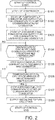
FIG. 2 is a flowchart illustrating the procedure of a start-up control of the fuel cell system according to the first embodiment. -
FIG. 3 is a flowchart illustrating the procedure of a stop control of the fuel cell system according to the first embodiment. -
FIG. 4 is a block diagram illustrating the main configuration of a fuel cell system according to a second embodiment. -
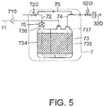
FIG. 5 is a block diagram illustrating the main configuration of a fuel cell system according to a third embodiment. -
FIG. 6 is a block diagram illustrating the main configuration of a fuel cell system according to a fourth embodiment. -
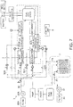
FIG. 7 is a block diagram illustrating the main configuration of a fuel cell system according to a fifth embodiment. - Hereinafter, exemplary embodiments of the present invention will be explained with reference to the accompanying drawings.
-
FIG. 1 is a block diagram illustrating the main configuration of a fuel cell system according to the first embodiment. Afuel cell system 100 according to the present embodiment includes: an anode gas supply system 2 (supply/ discharge mechanism) configured to supply an anode gas (fuel gas) to afuel cell stack 1; a cathode gas supply system 3 (supply/discharge mechanism) configured to supply a cathode gas (oxidant gas) to thefuel cell stack 1; a system discharge system (supply/discharge mechanism) configured to discharge a fuel offgas and an oxidation offgas discharged from thefuel cell stack 1; and a system drive system 5 configured to take out electric power from thefuel cell stack 1 to obtain power. - The anode
gas supply system 2 is connected to afuel tank 20 and includes afilter 21, apump 22, anevaporator 24, aheat exchanger 25, areformer 26, and the like, and a path 23 (path 23A) serially connecting these is connected to thefuel cell stack 1. In the anode gas supply system, theevaporator 24, theheat exchanger 25, and thereformer 26 constitute a fuel reforming system. The cathodegas supply system 3 is connected to a compressor 31 (oxidant gas supply source) and includes aheat exchanger 33, a start-up combustor 34, acatalyst combustor 35, and the like, and a path 32 (path 32A) serially-connecting these is connected to thefuel cell stack 1. In the cathodegas supply system 3, the start-up combustor 34 and thecatalyst combustor 35 constitute a start-up combustion system. The system discharge system includes a dischargedgas combustor 4 and the like. The system drive system 5 includes a DC-DC converter 50, abattery 51, adrive motor 52, and the like. Moreover, thefuel cell system 100 further includes acollection mechanism 7 to be described later connected to thefuel tank 20 and acontrol unit 9 that controls the overall operations of the fuel cell system. - Among the above components, the
fuel cell stack 1 and the supply/ discharge mechanism (theevaporator 24, theheat exchanger 25, thereformer 26, theheat exchanger 33, the start-up combustor 34, thecatalyst combustor 35, and the discharged gas combustor 4) are accommodated in a heat-insulatingcase 8, and thus the release of heat to the outside is reduced to suppress the temperature decrease of these during common power generation. - The
fuel cell stack 1 is a solid oxide fuel cell (SOFC) and is formed by stacking cells of which each obtained by sandwiching an electrolyte layer formed of solid oxide such as ceramic between an anode electrode (fuel electrode) to which anode gas reformed by thereformer 26 is supplied and a cathode electrode (air electrode) to which air containing oxygen is supplied as cathode gas. - Herein, an anode includes a passage in the
fuel cell stack 1 configured to supply anode gas to the anode electrode and a passage in thefuel cell stack 1 configured to discharge anode offgas after a reaction on the anode electrode as well as the anode electrode that constitutes thefuel cell stack 1. Similarly, a cathode includes a passage in thefuel cell stack 1 configured to supply cathode gas to the cathode electrode and a passage in thefuel cell stack 1 configured to discharge cathode offgas after a reaction on the cathode electrode as well as the cathode electrode that constitutes thefuel cell stack 1. - The
fuel cell stack 1 reacts therein hydrogen contained in the anode gas with oxygen in the cathode gas to generate electric power and discharges the anode offgas and cathode offgas generated after the reaction. Moreover, atemperature sensor 10 that measures the internal temperature of thefuel cell stack 1 is attached to thefuel cell stack 1. - The
path 23A configured to supply anode gas to the anode of thefuel cell stack 1, thepath 32A configured to supply combustion gas to the cathode of thefuel cell stack 1 during the start-up control of thefuel cell stack 1 and to supply cathode gas to the cathode of thefuel cell stack 1 during the power generation control, a dischargedgas path 27 configured to introduce anode offgas (fuel offgas) discharged from the anode of thefuel cell stack 1 into the dischargedgas combustor 4, and a dischargedgas path 36 configured to introduce cathode offgas (oxidation offgas) discharged from the cathode of thefuel cell stack 1 into the dischargedgas combustor 4 are connected to the fuel cell stack 1 (manifold). - The
fuel tank 20 stores therein reforming fuel consisting of liquid obtained by mixing ethanol and water, for example, and thepump 22 sucks the reforming fuel and supplies the reforming fuel to a fuel supply system at a predetermined pressure. Thefilter 21 is placed between thefuel tank 20 and thepump 22 to remove dust in the reforming fuel sucked by thepump 22. In addition, the reforming fuel vaporizes and vaporized fuel is accumulated in thefuel tank 20. Therefore, avapor line 71 introducing the vaporized fuel is provided on the upper portion of thefuel tank 20, and thevapor line 71 is connected to acollector 73 to be described later. - The
path 23 configured to supply reforming fuel from thefuel tank 20 branches to thepath 23A configured to supply the reforming fuel to theevaporator 24, a path 23B configured to supply fuel for combustion (reforming fuel) to the start-up combustor 34, apath 23C configured to supply the fuel for combustion to thecatalyst combustor 35, and apath 23D configured to supply the fuel for combustion to the dischargedgas combustor 4. An opening/closing valve 61A that can open and close the flow channel of thepath 23A is attached at an upstream-side position of the reforming fuel from theevaporator 24 of thepath 23A, and an injector 60A that injects the reforming fuel to theevaporator 24 is attached at its subsequent position. - Similarly, an opening/
closing valve 61B is attached to the path 23B, and aninjector 60B that injects the fuel for combustion to the start-up combustor 34 is attached at its subsequent position. An opening/closing valve 61C is attached to thepath 23C, and aninjector 60C that injects the fuel for combustion to thecatalyst combustor 35 is attached at its subsequent position. An opening/closing valve 61D is attached to thepath 23D, and aninjector 60D that injects the fuel for combustion to the dischargedgas combustor 4 is attached at its subsequent stage. - The opening/
closing valve 61B opens the path 23B to circulate the fuel for combustion during the start-up control of thefuel cell system 100, and closes the path 23B after the end of the start-up control. Similarly, the opening/closing valve 61C opens thepath 23C to circulate the fuel for combustion during the start-up control of thefuel cell system 100, and closes thepath 23C after the end of the start-up control. Moreover, the opening/closing valve 61A closes thepath 23A during the start-up control, but opens thepath 23A after the end of the start-up control to circulate the reforming fuel. The opening/closing valve 61D opens thepath 23D at a predetermined opening degree to circulate the fuel for combustion during the start-up control of thefuel cell system 100, but closes thepath 23D when the dischargedgas combustor 4 arrives at a predetermined temperature at which catalytic combustion can be performed. - The
evaporator 24 vaporizes the reforming fuel by using the heat of the discharged gas discharged from the dischargedgas combustor 4. Theheat exchanger 25 is supplied with heat from the dischargedgas combustor 4 and further heats the vaporized reforming fuel to reform the heated reforming fuel in thereformer 26. - The reformer 26 (fuel reforming mechanism) reforms the reforming fuel to anode gas containing hydrogen by using a catalytic reaction and supplies the anode gas to the anode of the
fuel cell stack 1. - The
compressor 31 takes in the outside air through thefilter 30 and supplies air to thefuel cell stack 1. Arelief valve 64 is attached to thepath 32 configured to supply air discharged by thecompressor 31. When a pressure in thepath 32 exceeds a predetermined value, therelief valve 64 opens thepath 32 to avoid a predetermined amount or more of load with respect to thecompressor 31. Moreover, thepath 32 branches to thepath 32A configured to supply air (cathode gas) to theheat exchanger 33, apath 32B configured to supply air to the start-up combustor 34, apath 32C configured to supply air to the heat exchanger 25 (the reformer 26), and apath 32D configured to supply air to the dischargedgas combustor 4. - A
throttle 62A is attached to thepath 32A, athrottle 62B is attached to thepath 32B, a throttle 62C is attached to thepath 32C, and athrottle 62D is attached to thepath 32D to be able to adjust the respective flow rates of air (cathode gas) by the control of thecontrol unit 9. Furthermore, aflashback arrester 63 configured to dam up flame is attached at a downstream-side position of air from each throttle of each path. - The
throttle 62A opens thepath 32A to circulate a predetermined amount of air during the start-up control of thefuel cell stack 1, but closes thepath 32A after the end of the start-up control. Similarly, thethrottle 62B opens thepath 32B to circulate a predetermined amount of air during the start-up control of thefuel cell stack 1, but closes thepath 32B after the end of the start-up control. The throttle 62C does not open thepath 32C during the start-up control of thefuel cell stack 1 but opens thepath 32C to circulate a predetermined amount of air (oxygen for reformulation adjustment) if needed during the power generation control of thefuel cell stack 1. Thethrottle 62D opens thepath 32D to circulate a predetermined amount of air during the start-up control of thefuel cell stack 1, but closes thepath 32D when the dischargedgas combustor 4 arrives at the temperature at which catalytic combustion can be performed. - The heat exchanger 33 heats air for combustion gas or air for cathode gas by using the heat of discharged gas discharged from the discharged
gas combustor 4. - The start-up
combustor 34 is supplied with the air heated by theheat exchanger 33 and the fuel for combustion supplied from theinjector 60B to mix both during the start-up control of thefuel cell system 100. Then, a mixture of the air and the fuel for combustion is ignited by an ignition device attached to the start-upcombustor 34 to generate high-temperature combustion gas. Moreover, air is introduced into the start-upcombustor 34 from thepath 32B and mixed gas of the combustion gas and the air is supplied to thecatalyst combustor 35. - During the start-up control of the
fuel cell system 100, thecatalyst combustor 35 mixes mixed gas of the air and combustion gas supplied from the start-upcombustor 34 with the fuel for combustion supplied from theinjector 60C to generate a great amount of combustion gas by using a catalytic reaction and supplies the generated combustion gas to thefuel cell stack 1. Herein, the catalyst combustor 35 heats a catalyst by using the mixed gas supplied from the start-upcombustor 34, but may heat a catalyst by using a heater. - After the end of the start-up control, the generation of combustion gas is terminated, and air passing through the
heat exchanger 33, the start-upcombustor 34, and thecatalyst combustor 35 is continuously used as cathode gas and is supplied to thefuel cell stack 1 to transfer to the power generation control. - During the power generation control, the discharged
gas combustor 4 mixes the anode offgas supplied from the dischargedgas path 27 with the cathode offgas supplied from the dischargedgas path 36 to combust its mixed gas by using a catalyst, generates discharged gas containing carbon dioxide and water as the main components, and transmits heat caused by catalytic combustion to theheat exchanger 25 etc. Moreover, during the start-up control, the dischargedgas combustor 4 mixes the fuel for combustion supplied from theinjector 60D with the air supplied from thepath 32D, combusts this mixed gas by using the attached ignition device, and generates discharged gas similar to the above. Furthermore, the dischargedgas combustor 4 is connected to adischarge path 41 configured to discharge the discharged gas after combustion, and thedischarge path 41 passes through theevaporator 24 and theheat exchanger 33 and is connected to a muffler (not illustrated). Therefore, theevaporator 24 and theheat exchanger 33 are heated by the discharged gas. In addition, atemperature sensor 40 that measures the temperature of the dischargedgas combustor 4 is attached to the dischargedgas combustor 4. - The
collection mechanism 7 includes the vapor line 71 (introduction path) connected to thefuel tank 20, thecollector 73 configured to collect the vaporized fuel supplied from thevapor line 71, asupply path 72 configured to supply gas for purge (air) to thecollector 73, and adischarge path 74 configured to discharge the purge gas from thecollector 73. InFIG. 1 , thesupply path 72 and thedischarge path 74 are incorporated into thepath 32D. Herein, a purge gas supply unit of thecollection mechanism 7 also serves as thecompressor 31. - A
backflow prevention valve 710 is attached to thevapor line 71. Thebackflow prevention valve 710 is a valve configured to open and close the vapor line by using a pressure difference. The backflow prevention valve opens thevapor line 71 when the pressure of thefuel tank 20 side is high, and conversely closes thevapor line 71 when the pressure of thecollector 73 side is high. Therefore, the circulation of vaporized fuel from thefuel tank 20 toward thecollector 73 is allowed, but the circulation of its backward-direction gas for purge (purge gas) etc. is prohibited. - An opening/
closing valve 720 is attached to thesupply path 72. The opening/closing valve 720 opens thesupply path 72 when turning on thethrottle 62D. In the stop control of thefuel cell stack 1, the opening/closing valve 720 closes thesupply path 72 after that thecompressor 31 is turned off. - The
collector 73 collects the vaporized fuel supplied from thevapor line 71. Thecollector 73 is partitioned into afront chamber 731 and arear chamber 732, and thefront chamber 731 and therear chamber 732 communicate with each other by aconnection passage 733. Aninlet port 736 to which thesupply path 72 is connected is provided on thefront chamber 731 and adischarge port 737 to which thedischarge path 74 is connected is provided on therear chamber 732. Moreover, aconnection port 738 to which thevapor line 71 is connected is provided on therear chamber 732. - The
front chamber 731 is filled up with acanister 734 formed of activated carbon etc. Similarly, therear chamber 732 is filled up with acanister 735. Thecanisters vapor line 71, but detach the adsorbed adsorption fuel by introducing gas for purge. - In a stage where the vaporized fuel begins to be adsorbed, the vaporized fuel adsorbed in the
canister 735 of therear chamber 732 is distributed near theconnection port 738 in thecanister 735. Then, depending on an increase in the adsorption amount of the vaporized fuel, the distribution of the vaporized fuel inside thecanister 735 expands toward theconnection passage 733, and the vaporized fuel arriving at theconnection passage 733 passes through theconnection passage 733 and arrives at and is adsorbed to thecanister 734 of thefront chamber 731. The vaporized fuel adsorbed to thecanister 734 is initially distributed near theconnection passage 733 in thecanister 734, but its distribution expands toward theinlet port 736 in thecanister 734 depending on an increase in the adsorption amount. - On the other hand, when introducing gas for purge from the
inlet port 736, the gas for purge penetrates into thefront chamber 731 and arrives at theconnection passage 733 through thecanister 734. Then, the gas for purge penetrates into therear chamber 732 and is discharged from thedischarge port 737 through thecanister 735. On this occasion, the vaporized fuel adsorbed to thecanisters canisters discharge port 737. In addition, because a pressure caused by the gas for purge (purge gas) is applied to thebackflow prevention valve 710 through theconnection port 738 regardless of the open/closed state of thethrottle 62D when thecompressor 31 is in an ON state, thebackflow prevention valve 710 closes thevapor line 71. - As described above, the
supply path 72 and thedischarge path 74 of thecollection mechanism 7 are incorporated into and united with thepath 32D, and thedischarge path 74 is connected to the dischargedgas combustor 4. For this reason, during the start-up control of thefuel cell stack 1, the dischargedgas combustor 4 is supplied with the fuel for combustion from thepath 23D and the gas for purge from thepath 32D. Because the vaporized fuel is contained in the purge gas discharged from thecollector 73, the supplied amount of the fuel for combustion to be supplied from thepath 32D can be reduced that much. - In the meantime, the present embodiment has a configuration that the collection mechanism 7 (the collector 73) is placed outside of the heat-insulating
case 8 and the discharge path 74 (thepath 32D) penetrates through the heat-insulatingcase 8. As a result, because thecollection mechanism 7 is substantially thermally insulated from a heat source such as thefuel cell stack 1 and the dischargedgas combustor 4, it is possible to avoid the deterioration of thecanisters - As illustrated in
FIG. 1 , in the present embodiment, the collection mechanism 7 (the collector 73) can be incorporated into thepath 32A, thepath 32B, thepath 32C, or thepath 32 besides thepath 32D. When thecollection mechanism 7 is incorporated into thepath 32A, thesupply path 72 and thedischarge path 74 are united with thepath 32A and thus are connected to theheat exchanger 33. When thecollection mechanism 7 is incorporated into thepath 32B, thesupply path 72 and thedischarge path 74 are united with thepath 32B and thus are connected to the start-upcombustor 34. When thecollection mechanism 7 is incorporated into thepath 32C, thesupply path 72 and thedischarge path 74 are united with thepath 32C and thus are connected to the heat exchanger 25 (the reformer 26). When thecollection mechanism 7 is incorporated into thepath 32, thesupply path 72 and thedischarge path 74 are united with thepath 32 and then are branched, and consequently are connected to theheat exchanger 33, the start-upcombustor 34, the heat exchanger 25 (the reformer 26), and the dischargedgas combustor 4. Furthermore, thesupply path 72 of thecollection mechanism 7 can be incorporated into at least one of thepath 32 and thepath 32A to thepath 32D and thedischarge path 74 can be connected to the dischargedgas path 27 and/or the dischargedgas path 36. Moreover, among the components of thecollection mechanism 7, thesupply path 72 is branched from thepath 32 and thedischarge path 74 is delinked from thepath 32 and is optionally branched to join at least two of thepath 32A, thepath 32B, thepath 32C, and thepath 32D. - When the
collection mechanism 7 is incorporated into thepath 32A, the vaporized fuel can be discharged into thepath 32A during the start-up control and the power generation control of thefuel cell stack 1. The vaporized fuel discharged from thecollection mechanism 7 is heated by theheat exchanger 33. During the start-up control, the vaporized fuel is combusted in the start-upcombustor 34 or thecatalyst combustor 35. Therefore, the supplied amount of the fuel for combustion to the start-upcombustor 34 and thecatalyst combustor 35 can be reduced that much. On the other hand, during the power generation control, the vaporized fuel passes through thefuel cell stack 1 and is combusted in the dischargedgas combustor 4. - When the
collection mechanism 7 is incorporated into thepath 32B, it is possible to discharge the vaporized fuel into thepath 32A to supply it to the start-upcombustor 34 during the start-up control of thefuel cell stack 1. Therefore, the supplied amount of the fuel for combustion to the start-upcombustor 34 and thecatalyst combustor 35 can be reduced that much. - When the
collection mechanism 7 is incorporated into thepath 32C, it is possible to discharge the vaporized fuel into thepath 32C to supply it to the heat exchanger 25 (the reformer 26) during the power generation control of thefuel cell stack 1. Therefore, the supplied amount of the reforming fuel to thereformer 26 can be reduced that much. - When the
collection mechanism 7 is incorporated into thepath 32, the vaporized fuel can be discharged into thepath 32 during the start-up control and the power generation control of thefuel cell stack 1. At this time, thedischarge path 74 is branched and consequently is connected to the dischargedgas combustor 4, the start-upcombustor 34, theheat exchanger 33, and thereformer 26. Due to the incorporation in this way, because the supply destination of the vaporized fuel collected by thecollection mechanism 7 is dispersed and thus the vaporized fuel to be supplied to the supply destination becomes smaller that much, the change of state of the device located at the supply destination can be made smaller to stably activate the whole system. Moreover, because the flow rate of air (gas for purge) from thecompressor 31 is the most, the vaporized fuel can be efficiently discharged from thecanisters - In any case, the present embodiment requires a configuration to combust the vaporized fuel collected by the
collection mechanism 7 to discharge it to the outside. For this reason, thedischarge path 74 at least only needs to be connected to an upstream-side position from an outlet of the dischargedgas combustor 4 in the supply/discharge mechanism described above, namely, in the paths (thepath 23, thepaths 23A to 23D, and the discharged gas path 27) through which anode gas circulates or the paths (thepath 32, thepaths 32A to 32D, and the discharged gas path 36) through which cathode gas circulates. - The DC-
DC converter 50 is connected to thefuel cell stack 1, and raises the output voltage of thefuel cell stack 1 to supply electric power to thebattery 51 or thedrive motor 52. Thebattery 51 is charged with electric power supplied from the DC-DC converter 50 and supplies the electric power to thedrive motor 52. Thedrive motor 52 is connected to thebattery 51 and the DC-DC converter 50 via an inverter (not illustrated), and acts as a power source of a vehicle. Moreover, during braking the vehicle, thedrive motor 52 generates regenerative electric power and thebattery 51 can be charged with this electric power. - The
battery 51 and thedrive motor 52 act as a load connected to thefuel cell stack 1 via the DC-DC converter 50. On the other hand, auxiliary machines, such as thepump 22 and thecompressor 31, to make thefuel cell stack 1 generate electric power can be connected to thefuel cell stack 1 as a load to be driven by the supply of power from thefuel cell stack 1, but may be driven by the supply of power from thebattery 51. - The
control unit 9 is configured to include general-purpose electronic circuit and peripheral device that include a microcomputer, a microprocessor, and/or a CPU, and executes a specified program to execute a process for controlling thefuel cell system 100. Moreover, thecontrol unit 9 can perform the drive/stop control (ON/OFF control) for components that constitutes thefuel cell system 100. The control of thefuel cell system 100 that is performed by thecontrol unit 9 as described below includes the start-up control for performing heating so that thefuel cell stack 1 can generate electric power, the power generation control for performing normal power generation, and the stop control for stopping the system. In addition, in order to suppress the deterioration of the anode (the anode electrode), the stop control of thefuel cell stack 1 requires to apply a voltage about the open voltage of thefuel cell stack 1 as a protective voltage. For this reason, after connecting a protection circuit (not illustrated) configured to apply this protective voltage to thefuel cell stack 1, thecontrol unit 9 may drive the protection circuit (not illustrated) during the stop control of thefuel cell stack 1. - Next, the procedure of the start-up control of the
fuel cell system 100 will be explained in accordance with a flowchart illustrated inFIG. 2 . In an initial state, the opening/closing valves 61A to 61D and thethrottles 62A to 62D are turned off. As illustrated inFIG. 2 , when the system starts the start-up control, thecontrol unit 9 turns on thecompressor 31, thethrottle 62A, and thethrottle 62B at a constant opening degree in Step S101. As a result, air is supplied to thepath 32, thepath 32A, and thepath 32B. - In Step S102, the
control unit 9 turns on thepump 22 and the start-upcombustor 34, and turns on the opening/closing valve 61B, the opening/closing valve 61C, and the opening/closing valve 61D. As a result, the start-upcombustor 34 generates combustion gas, and thecatalyst combustor 35 generates a large amount of combustion gas and supplies it to thefuel cell stack 1 to heat thefuel cell stack 1. Then, the combustion gas (discharged gas) passing through thefuel cell stack 1 arrives at the dischargedgas combustor 4 through the dischargedgas path 36. - In Step S103, the
control unit 9 turns on the dischargedgas combustor 4, the opening/closing valve 61D, the opening/closing valve 720, and thethrottle 62D. As a result, the air (gas for purge) supplied from thepath 32D is mixed with the fuel for combustion supplied from thepath 32D and the mixed gas is combusted to generate discharged gas. Herein, the air (purge gas) passing through thecollector 73 contains vaporized fuel, but this vaporized fuel is also combusted in the dischargedgas combustor 4. The discharged gas generated from the dischargedgas combustor 4 heats the dischargedgas combustor 4 itself. Moreover, the dischargedgas combustor 4 is also heated by the combustion gas (discharged gas) discharged from thefuel cell stack 1. The heat generated in the dischargedgas combustor 4 is transmitted to theheat exchanger 25 and thereformer 26. Then, the discharged gas discharged from the dischargedgas combustor 4 is discharged to the outside through theevaporator 24 and theheat exchanger 33. Therefore, theevaporator 24 and theheat exchanger 33 are heated by the discharged gas. In addition, Steps S102 and S103 may be simultaneously performed. - In Step S104, based on the temperature measured by the
temperature sensor 40, thecontrol unit 9 determines whether the temperature of the dischargedgas combustor 4 arrives at a predetermined temperature at which catalytic combustion can be performed. The control unit transfers to the next Step S105 if it is YES (positive), and maintains the state after Step S103 if it is NO (negative). - In Step S105, the
control unit 9 turns off the ignition device of the dischargedgas combustor 4 and turns off the opening/closing valve 61D and thethrottle 62D. As a result, the discharge of the vaporized fuel from thecollection mechanism 7 is stopped. On the other hand, the dischargedgas combustor 4 is continuously heated by the combustion gas (discharged gas) supplied from thefuel cell stack 1. - In Step S106, based on the temperature measured by the
temperature sensor 10, thecontrol unit 9 determines whether the temperature of thefuel cell stack 1 arrives at a predetermined temperature at which power generation can be performed. The control unit transfers to the next Step S107 if it is YES (positive), and maintains the state after Step S105 if it is NO (negative). - In Step S107, the
control unit 9 turns off the opening/closing valve 61B and the opening/closing valve 61C to stop supplying the fuel for combustion to the start-upcombustor 34 and thecatalyst combustor 35 and turns off thethrottle 62B to stop supplying the air to the start-upcombustor 34, so as to stop generating the combustion gas. On the other hand, thecontrol unit 9 maintains the ON state of thethrottle 62A. As a result, the air (cathode gas) heated by theheat exchanger 33 is supplied to thefuel cell stack 1. - In Step S108, the
control unit 9 turns on the opening/closing valve 61A to supply the reforming fuel to theevaporator 24. As a result, the reforming fuel is heated and vaporized in theevaporator 24, is further heated in theheat exchanger 25, and is reformed to anode gas in thereformer 26 and then is supplied to thefuel cell stack 1. According to this, because thefuel cell stack 1 enters a state where power generation can be performed by the anode gas supplied to the anode and the cathode gas supplied to the cathode, the control unit terminates the start-up control. - Next, operations during the power generation control of the
fuel cell system 100 will be explained. During the power generation control of the system, the reforming fuel supplied from thefuel tank 20 is first reformed to anode gas by thereformer 26 and is supplied to the anode of thefuel cell stack 1. On the other hand, air acting as cathode gas is heated by theheat exchanger 33 and is supplied to the cathode of thefuel cell stack 1. - The
fuel cell stack 1 supplied with the anode gas and cathode gas generates electric power by using an electrochemical reaction and supplies the electric power in accordance with the required power of thebattery 51 and the drive motor 52 (the DC-DC converter 50) and the further required power of auxiliary machines such as thepump 22 and thecompressor 31, and introduces the anode offgas and cathode offgas used for the electrochemical reaction into the dischargedgas combustor 4. - The discharged
gas combustor 4 combusts the anode offgas and cathode offgas in a state where they are mixed to generate discharged gas. The discharged gas passes through theevaporator 24 and theheat exchanger 33 while heating them and is discharged to the outside. At this time, as illustrated inFIG. 1 , when thecollection mechanism 7 is incorporated into thepath 32C, thecontrol unit 9 turns on the throttle 62C if needed so as to be able to supply the vaporized fuel to thereformer 26. - Next, the procedure of the stop control of the
fuel cell system 100 will be explained in accordance with a flowchart illustrated inFIG. 3 . When the system starts the stop control, thecontrol unit 9 turns off thepump 22 and turns off the opening/closing valve 61A to stop supplying the anode gas in Step S201. As a result, the power generation of thefuel cell stack 1 is stopped. Moreover, thecontrol unit 9 maintains the ON state of thethrottle 62A. As a result, the cathode gas is continuously introduced into thefuel cell stack 1 as coolant gas, and thus the temperature of thefuel cell stack 1 is decreased. Furthermore, the control unit drives the protection circuit (not illustrated) configured to apply a protective voltage to thefuel cell stack 1. As a result, the deterioration of the anode electrode is avoided. - In Step S202, based on the temperature measured by the
temperature sensor 10, thecontrol unit 9 determines whether the temperature of thefuel cell stack 1 is decreased up to an upper limit temperature at which the deterioration of the anode can be avoided. The control unit maintains the state after Step S201 when determining that it is NO (negative), and transfers to the next Step S203 when determining that it is YES. - In Step S203, the
control unit 9 turns off the protection circuit (not illustrated) to stop applying the protective voltage. Moreover, thecontrol unit 9 turns off thecompressor 31 and thethrottle 62A. As a result, the pressure in thepath 32 and thepaths 32A to 32D returns to atmospheric pressure, and thus becomes the same as a pressure in thefuel tank 20 or becomes smaller than the pressure in the fuel tank. Therefore, thebackflow prevention valve 710 opens the vapor line, and thus the vaporized fuel that is vaporized in thefuel tank 20 again arrives at thecollection mechanism 7 through thevapor line 71 to make thecollection mechanism 7 restart the collection of the vaporized fuel. - In Step S204, the
control unit 9 turns off the opening/closing valve 720 of thecollection mechanism 7 to close thesupply path 72 of the gas for purge in thecollection mechanism 7. As a result, thecompressor 31 is prevented from being deteriorated due to the arrival of the vaporized fuel, which is discharged from thecanisters inlet port 736, at thecompressor 31. According to this, the stop control of thefuel cell stack 1 is terminated. - As described above, the
fuel cell system 100 according to the first embodiment includes: thefuel cell stack 1 that is supplied with anode gas and cathode gas to generate electric power; thefuel tank 20 that stores therein liquid fuel acting as the anode gas; thecompressor 31 that supplies the cathode gas; and the supply/discharge mechanism (theevaporator 24, theheat exchanger 25, thereformer 26, theheat exchanger 33, the start-upcombustor 34, thecatalyst combustor 35, and the discharged gas combustor 4) that is connected to thefuel tank 20 and thecompressor 31, the supply/ discharge mechanism being configured to supply/ discharge the fuel gas and the oxidant gas to/from thefuel cell stack 1. Thefuel cell system 100 further includes: thecollector 73 configured to collect vaporized fuel that is vaporized in thefuel tank 20; thevapor line 71 that is connected to thefuel tank 20 and thecollector 73 to guide the vaporized fuel to thecollector 73; thedischarge path 74 configured to discharge the vaporized fuel collected by thecollector 73 to the supply/discharge mechanism; and thesupply pass 72 and the purge gas supply unit (the compressor 31) that are connected to thecollector 73 to supply to thecollector 73 the gas for purge for pushing out the vaporized fuel collected by thecollector 73 into thedischarge path 74. - As a result, because the purge gas supply unit (the compressor 31) does not directly touch fuel, the deterioration of the purge gas supply unit can be avoided. Furthermore, because the purge gas supply unit (the compressor 31) does not communicate with the
reformer 26 etc. close to thefuel cell stack 1, the purge gas supply unit can also avoid being deteriorated due to heat from thefuel cell stack 1 and thereformer 26. - The purge gas supply unit also serves as the
compressor 31, and the cathode gas is supplied to thecollector 73 as the gas for purge. As a result, because a supply source to supply cathode gas and a supply source to supply gas for purge are united with each other, the whole system can be downsized. - The supply/discharge mechanism includes the discharged
gas combustor 4 that is placed at the downstream-side position from thefuel cell stack 1, and thedischarge path 74 is configured to supply the vaporized fuel to the dischargedgas combustor 4. As a result, the dischargedgas combustor 4 having high combustion efficiency can surely combust the vaporized fuel collected by thecollector 73. - The supply/discharge mechanism includes the start-up
combustor 34 that is placed at a position between thecompressor 31 and thefuel cell stack 1 and mixes the fuel for combustion with the cathode gas and ignites the mixture to generate combustion gas and supply it to thefuel cell stack 1, and thedischarge path 74 is configured to discharge the vaporized fuel to the start-upcombustor 34. As a result, during the start-up control of thefuel cell system 100, the vaporized fuel collected by thecollector 73 can be surely combusted in the start-upcombustor 34. Moreover, the supplied amount of the fuel for combustion to the start-upcombustor 34 can be reduced as much as the vaporized fuel is supplied thereto. - The supply/discharge mechanism includes: the
heat exchanger 33 that is placed at a position between thecompressor 31 and thefuel cell stack 1 to heat cathode gas by using the discharged gas discharged from thefuel cell stack 1; and thecatalyst combustor 35 that is placed at a position between theheat exchanger 33 and thefuel cell stack 1 and mixes the fuel for combustion with the cathode gas to generate combustion gas and supply it to thefuel cell stack 1, and thedischarge path 74 is configured to discharge the vaporized fuel to theheat exchanger 33. As a result, the vaporized fuel collected by thecollection mechanism 7 can be combusted by the dischargedgas combustor 4 at least located at the downstream side from thepath 32A. Moreover, during the start-up control of thefuel cell system 100, because the vaporized fuel (vaporized fuel that is not combusted in the start-up combustor 34) heated in theheat exchanger 33 is supplied to thecatalyst combustor 35, it is possible to raise the combustion efficiency of the vaporized fuel. - The supply/discharge mechanism includes the
reformer 26 that is placed at a position between thefuel tank 20 and thefuel cell stack 1 to reform liquid fuel to anode gas, and thedischarge path 74 is configured to discharge the vaporized fuel to thereformer 26. As a result, during the power generation control of thefuel cell system 100, the vaporized fuel collected by thecollector 73 can be surely reformed in thereformer 26. Moreover, the supplied amount of the reforming fuel to thereformer 26 can be reduced as much as the vaporized fuel is supplied thereto. - The supply/discharge mechanism includes: the discharged
gas combustor 4 that is placed at the downstream-side position from thefuel cell stack 1 and theheat exchanger 25 that is placed at a position between thefuel tank 20 and thereformer 26 to heat liquid fuel by using heat from the dischargedgas combustor 4 during the combustion of discharged gas, and thedischarge path 74 is configured to supply the vaporized fuel upstream of theheat exchanger 25. As a result, it is possible to raise the reforming efficiency of vaporized fuel in thereformer 26 because the vaporized fuel discharged from thecollector 73 is heated by theheat exchanger 25. - The supply/discharge mechanism includes: the discharged
gas combustor 4 that is placed at the downstream-side position from thefuel cell stack 1; thereformer 26 that is placed at a position between thefuel tank 20 and thefuel cell stack 1 to reform liquid fuel to anode gas; theheat exchanger 33 that is placed at a position between thecompressor 31 and thefuel cell stack 1 to heat cathode gas by using discharged gas discharged from thefuel cell stack 1; and the start-upcombustor 34 that is placed at a position between theheat exchanger 33 and thefuel cell stack 1 and mixes the fuel for combustion with the cathode gas heated by theheat exchanger 33 and ignites the mixture to generate combustion gas and supply the combustion gas to thefuel cell stack 1. Thedischarge path 74 is configured to discharge the vaporized fuel to at least two of thereformer 26, theheat exchanger 33, the start-upcombustor 34, and the dischargedgas combustor 4. As a result, because the discharge destination of the vaporized fuel collected by thecollector 73 is dispersed and thus the vaporized fuel to be supplied to the discharge destination becomes smaller that much, the change of state of the device located at the discharge destination can be made smaller to stably activate the whole system. - The supply/discharge mechanism includes: the discharged
gas combustor 4 that is placed at the downstream-side position from thefuel cell stack 1; the fuel reforming mechanism (theevaporator 24, theheat exchanger 25, and the reformer 26) that is placed at a position between thefuel tank 20 and thefuel cell stack 1 to heat liquid fuel and reform it to anode gas; theheat exchanger 33 that is placed at a position between thecompressor 31 and thefuel cell stack 1 to heat cathode gas; the start-up combustion system (the start-upcombustor 34 and the catalyst combustor 35) that is placed at a position between theheat exchanger 33 and thefuel cell stack 1 and mixes the fuel for combustion with the cathode gas heated by theheat exchanger 33 and ignites the mixture to generate combustion gas and supply the combustion gas to thefuel cell stack 1; and the heat-insulatingcase 8 that accommodates thefuel cell stack 1, the fuel reforming mechanism, theheat exchanger 33, the start-up combustion system, and the dischargedgas combustor 4. Thecollection mechanism 7 is placed outside of the heat-insulatingcase 8, and thedischarge path 74 penetrates through the heat-insulatingcase 8. As a result, because thecollection mechanism 7 is substantially thermally insulated from a heat source such as thefuel cell stack 1 and the dischargedgas combustor 4, the collection mechanism 7 (thecanisters 734 and 735) can avoid being deteriorated due to heat. In addition, the heat-insulatingcase 8 may be configured to accommodate at least thefuel cell stack 1 and the dischargedgas combustor 4. -
FIG. 4 is a block diagram illustrating the main configuration of a fuel cell system according to the second embodiment. The illustration of surrounding components of thecollection mechanism 7 is omitted in the second embodiment (third embodiment, fourth embodiment). The basic configuration according to the second embodiment is common to that of the first embodiment, but the configuration of thecollection mechanism 7 is different from that of the first embodiment. - The
collection mechanism 7 includes afirst bypass line 75 that is connected to thesupply path 72 and thedischarge path 74 to bypass thecollector 73. Thefirst bypass line 75 is connected to the downstream-side position from the opening/closing valve 720 of thesupply path 72. Thefirst bypass line 75 has an inside diameter etc. that are designed so that the pressure loss of the gas for purge is smaller than thecollector 73 and the flow rate of the gas for purge is larger than thecollector 73. As a result, because the pressure loss of the path supplying air (cathode gas) through thecollector 73 is reduced, the burden of the compressor 31 (FIG. 1 ) can be reduced. Moreover, because a large pressure is not also applied to thecollector 73, a burden on the collector 73 (thecanisters 734 and 735) can be reduced. - Moreover, the
first bypass line 75 has an inside diameter etc. that are designed so that the pressure loss of the gas for purge is smaller than thecollector 73 and the flow rate of the gas for purge is larger than thecollector 73. As a result, even if the supplied amount of cathode gas of thecompressor 31 is large, thecollector 73 can be protected from the pressure of cathode gas. -
FIG. 5 is a block diagram illustrating the main configuration of a fuel cell system according to the third embodiment. The basic configuration according to the third embodiment is common to that of the second embodiment, but avalve 76 is provided at theinlet port 736 of thecollector 73. - The vaporized fuel collected by the
collector 73 can be discharged by supplying gas for purge to thecollector 73. However, when the gas for purge is supplied to thecollector 73, the distribution density of the vaporized fuel inside thecanisters collector 73 is decreased with the passage of time. Therefore, when discharging the vaporized fuel from thecollector 73, the present embodiment initially sets the opening degree of thevalve 76 to a low value to lower the supplied amount of the gas for purge to be introduced into thecollector 73 and then makes the opening degree of thevalve 76 larger to increasingly increase the supplied amount of the gas for purge with the passage of time. As a result, the time-direction unevenness of the discharge amount of the vaporized fuel can be suppressed to stabilize the control of the device located at the discharge destination. - The control unit 9 (
FIG. 1 ) turns on the opening/closing valve 720 and thethrottle 62D and turns on thevalve 76, but initially performs control of making their opening degrees smaller and increasingly making their opening degrees larger with the passage of time. In addition, inFIG. 5 , thevalve 76 is attached to theinlet port 736, but may be attached to thedischarge port 737 or may be attached to theinlet port 736 and thedischarge port 737. -
FIG. 6 is a block diagram illustrating the main configuration of a fuel cell system according to the fourth embodiment. The basic configuration according to the fourth embodiment is common to that of the second embodiment, but thesupply path 72 branches to asecond bypass line 78 and abranch path 721 circulating through thecollector 73 by using a three-way valve 77 (changeover valve) as a branching point. Thebranch path 721 and thesecond bypass line 78 join each other at thedischarge path 74. - The three-
way valve 77 is controlled by the control unit 9 (FIG. 1 ), and causes the circulation path communicating with thesupply path 72 to switch between thebranch path 721 and thesecond bypass line 78 or adjusts a circulation ratio of air between thebranch path 721 and thesecond bypass line 78. - The
second bypass line 78 includes a component such as a damper such that the pressure loss of gas for purge is substantially equal to that of thecollector 73 and the flow rate of gas for purge is substantially the same as that of thecollector 73. - In the present embodiment, the three-
way valve 77 fully opens thesecond bypass line 78 in an initial state. As a result, thecollector 73 is opened only with respect to thefuel tank 20, and thus the vaporized fuel can be adsorbed to thecanisters compressor 31, the opening/closing valve 720, and thethrottle 62D so as to make air circulate through the first andsecond bypass lines discharge port 737 from the first andsecond bypass lines backflow prevention valve 710 closes thevapor line 71 due to the pressure of the air. - In this state, the
control unit 9 performs switching control on the three-way valve 77 to fully open thebranch path 721. As a result, the air to circulate through thesecond bypass line 78 can be supplied to thecollector 73 as gas for purge at substantially the same flow rate, and thus the vaporized fuel collected by thecollector 73 can be discharged from thedischarge port 737. By performing control in this way, the vaporized fuel can be discharged at an arbitrary time when air is being supplied to thecollection mechanism 7. Moreover, because there is no change in the pressure loss of thecollection mechanism 7 before and after the discharge of vaporized fuel, the pulsation of the flow rate of air can be suppressed and thus a vibration and the deterioration of the device caused by this pulsation can be suppressed. - Similarly to the third embodiment, the present embodiment can suppress the time-direction unevenness of the discharge amount of vaporized fuel. In other words, when supplying the gas for purge to the
collector 73, the present embodiment initially sets the opening degree of the three-way valve 77 related to thebranch path 721 to a small value and the opening degree of the three-way valve 77 related to thesecond bypass line 78 to a large value to lower the supplied amount of gas for purge to be introduced into thecollector 73. Then, the present embodiment controls the opening degrees of the three-way valve 77, in such a manner that the opening degree related to thebranch path 721 is larger than the opening degree related to thesecond bypass line 78 with the passage of time, to increase the supplied amount of gas for purge to be introduced into thecollector 73. Finally, the present embodiment only needs to perform control on the three-way valve 77 to fully open thebranch path 721 and fully close thesecond bypass line 78. InFIG. 6 , thevalve 76 is not attached, but the present embodiment may attach thevalve 76 to thecollector 73 similarly to the third embodiment to perform interlocking control of the three-way valve 77 and thevalve 76. Moreover, thefirst bypass line 75 may be omitted inFIG. 6 . -
FIG. 7 is a block diagram illustrating the main configuration of a fuel cell system according to the fifth embodiment. The basic configuration of the fuel cell system according to the fifth embodiment is common to the first embodiment, but a purge gas supply source (the compressor 31) and thefilter 30 that constitute thecollection mechanism 7 are separated from the cathodegas supply system 3. On the other hand, the cathodegas supply system 3 includes acompressor 31A and afilter 30A that are dedicated thereto. Thecompressor 31A is controlled in a similar manner to thecompressor 31 that is used in the first to fourth embodiments. - Moreover, the
supply path 72 and thedischarge path 74 that constitutes thecollection mechanism 7 are separated from thepath 32 of the cathodegas supply system 3 and thepaths 32A to 32D that branch from thepath 32.FIG. 7 illustrates the state where thedischarge path 74 is connected to thepath 32D with a solid line. However, as indicated by a dashed line ofFIG. 7 , thedischarge path 74 can be connected to any of thepath 32, thepath 32A, thepath 32B, thepath 32C, and thepath 32D. Herein, when air circulates through the path connected to thedischarge path 74, thecontrol unit 9 can drive thecompressor 31 to discharge the vaporized fuel collected by thecollection mechanism 7 to the connected path. - As described above, by separating a supply source configured to supply air (cathode gas) to the
fuel cell stack 1 and a supply source configured to supply gas for purge to thecollection mechanism 7, the burden of each supply source can be reduced. - As described above, the embodiments of the present invention have been explained, but the above embodiments are only a part of the application example of the present invention and the technical scope of the present invention is not intended to be limited to the specific configurations of the above embodiments.
Claims (14)
- A fuel cell system comprising:a fuel cell that is supplied with a fuel gas and an oxidant gas to generate electric power;a fuel tank that stores therein liquid fuel acting as the fuel gas;an oxidant gas supply source configured to supply the oxidant gas;a supply/discharge mechanism that is connected to the fuel tank and the oxidant gas supply source, the supply/discharge mechanism being configured to supply and discharge the fuel gas and the oxidant gas to and from the fuel cell;a collector configured to collect vaporized fuel that is vaporized in the fuel tank;an introduction path that is connected to the fuel tank and the collector, the introduction path being configured to guide the vaporized fuel to the collector;a discharge path configured to discharge the vaporized fuel collected by the collector to the supply/discharge mechanism; anda supply path and a purge gas supply unit that are connected to the collector, the supply path and the purge gas supply unit being configured to supply, to the collector, purge gas for pushing out the vaporized fuel collected by the collector into the discharge path.
- The fuel cell system according to claim 1, wherein
the purge gas supply unit also serves as the oxidant gas supply source, and
the oxidant gas is supplied to the collector as the purge gas. - The fuel cell system according to claim 1 or 2, further comprising:
a first bypass line that is connected to the introduction path and the discharge path to bypass the collector. - The fuel cell system according to claim 3, wherein the first bypass line is configured so that a flow rate of the purge gas is more than that of the collector.
- The fuel cell system according to claim 3 or 4, wherein the collector includes a valve that is provided on at least one of an introduction side of the purge gas and a discharge side of the vaporized fuel, the valve controlling a flow rate of the purge gas to be supplied to the collector.
- The fuel cell system according to claim 1 or 2, further comprising:a second bypass line that is connected to the introduction path and the discharge path to bypass the collector; anda changeover valve that switches between the second bypass line and the collector to select a circulation path of the purge gas, whereinflow rates of the purge gas in the collector and the second bypass line are substantially same.
- The fuel cell system according to any one of claims 1 to 6, wherein
the supply/discharge mechanism includes a discharged gas combustor that is placed at a downstream-side position from the fuel cell, and
the discharge path is configured to supply the vaporized fuel to the discharged gas combustor. - The fuel cell system according to any one of claims 1 to 6, wherein
the supply/discharge mechanism includes a start-up combustor that is placed at a position between the oxidant gas supply source and the fuel cell, the start-up combustor mixing fuel for combustion with the oxidant gas and igniting a mixture to generate combustion gas and supply the combustion gas to the fuel cell, and
the discharge path is configured to discharge the vaporized fuel to the start-up combustor. - The fuel cell system according to any one of claims 1 to 6, wherein
the supply/discharge mechanism includes:a heat exchanger that is placed at a position between the oxidant gas supply source and the fuel cell, the heat exchanger heating the oxidant gas by using discharged gas discharged from the fuel cell; anda catalyst combustor that is placed at a position between the heat exchanger and the fuel cell, the catalyst combustor mixing fuel for combustion with the oxidant gas to generate combustion gas and supply the combustion gas to the fuel cell, andthe discharge path is configured to discharge the vaporized fuel to the heat exchanger. - The fuel cell system according to any one of claims 1 to 6, wherein
the supply/discharge mechanism includes a reformer that is placed at a position between the fuel tank and the fuel cell, the reformer reforming the liquid fuel to the fuel gas, and
the discharge path is configured to discharge the vaporized fuel to the reformer. - The fuel cell system according to claim 10, wherein
the supply/discharge mechanism includes:a discharged gas combustor that is placed at a downstream-side position from the fuel cell; anda heat exchanger that is placed at a position between the fuel tank and the reformer, the heat exchanger heating the liquid fuel by using heat from combustion of discharged gas performed by the discharged gas combustor, andthe discharge path supplies the vaporized fuel upstream of the heat exchanger. - The fuel cell system according to any one of claims 1 to 6, wherein
the supply/discharge mechanism includes:a discharged gas combustor that is placed at a downstream-side position from the fuel cell;a reformer that is placed at a position between the fuel tank and the fuel cell, the reformer reforming the liquid fuel to the fuel gas;a heat exchanger that is placed at a position between the oxidant gas supply source and the fuel cell, the heat exchanger heating the oxidant gas by using discharged gas discharged from the fuel cell; anda start-up combustor that is placed at a position between the heat exchanger and the fuel cell, the start-up combustor mixing fuel for combustion with the oxidant gas heated by the heat exchanger to generate combustion gas and supply the combustion gas to the fuel cell, andthe discharge path is configured to discharge the vaporized fuel to at least two of the reformer, the heat exchanger, the start-up combustor, and the discharged gas combustor. - The fuel cell system according to any one of claims 1 to 6, wherein
the supply/discharge mechanism includes a discharged gas combustor that is placed at a downstream-side position from the fuel cell,
the fuel cell and the discharged gas combustor are accommodated in a heat-insulating case,
the collector is placed outside of the heat-insulating case, and
the discharge path penetrates through the heat-insulating case. - The fuel cell system according to any one of claims 1 to 6, wherein
the supply/discharge mechanism includes:a discharged gas combustor that is placed at a downstream-side position from the fuel cell;a fuel reforming system that is placed at a position between the fuel tank and the fuel cell, the fuel reforming system being configured to heat the liquid fuel and reform the liquid fuel to the fuel gas;a heat exchanger that is placed at a position between the oxidant gas supply source and the fuel cell, the heat exchanger heating the oxidant gas; anda start-up combustion system that is placed at a position between the heat exchanger and the fuel cell, the start-up combustion system being configured to mix fuel for combustion with the oxidant gas heated by the heat exchanger to generate combustion gas and supply the combustion gas to the fuel cell,the fuel cell, the fuel reforming system, the heat exchanger, the start-up combustion system, and the discharged gas combustor are accommodated in a heat-insulating case,the collector is placed outside of the heat-insulating case, andthe discharge path penetrates through the heat-insulating case.
Applications Claiming Priority (1)
| Application Number | Priority Date | Filing Date | Title |
|---|---|---|---|
| PCT/JP2016/077298 WO2018051468A1 (en) | 2016-09-15 | 2016-09-15 | Fuel cell system |
Publications (3)
| Publication Number | Publication Date |
|---|---|
| EP3514874A1 true EP3514874A1 (en) | 2019-07-24 |
| EP3514874A4 EP3514874A4 (en) | 2019-10-09 |
| EP3514874B1 EP3514874B1 (en) | 2021-07-28 |
Family
ID=61618698
Family Applications (1)
| Application Number | Title | Priority Date | Filing Date |
|---|---|---|---|
| EP16916250.0A Active EP3514874B1 (en) | 2016-09-15 | 2016-09-15 | Fuel cell system |
Country Status (5)
| Country | Link |
|---|---|
| US (1) | US11127969B2 (en) |
| EP (1) | EP3514874B1 (en) |
| JP (1) | JP6981418B2 (en) |
| CN (2) | CN109716568A (en) |
| WO (1) | WO2018051468A1 (en) |
Families Citing this family (3)
| Publication number | Priority date | Publication date | Assignee | Title |
|---|---|---|---|---|
| JP7234507B2 (en) * | 2018-05-11 | 2023-03-08 | 日産自動車株式会社 | FUEL COMBUSTION SYSTEM, FUEL CELL SYSTEM, AND FUEL COMBUSTION METHOD |
| JP2022143747A (en) * | 2021-03-18 | 2022-10-03 | 本田技研工業株式会社 | Fuel cell system and low temperature start method thereof |
| JPWO2023007555A1 (en) | 2021-07-26 | 2023-02-02 |
Family Cites Families (18)
| Publication number | Priority date | Publication date | Assignee | Title |
|---|---|---|---|---|
| JP2000192863A (en) * | 1998-12-25 | 2000-07-11 | Aisan Ind Co Ltd | Fuel vapor processing device for vehicle |
| DE10063648B4 (en) | 2000-12-20 | 2006-12-14 | Nucellsys Gmbh | Fuel cell system and method for operating the fuel cell system |
| US6463889B2 (en) * | 2001-03-08 | 2002-10-15 | General Motors Corporation | POx cold start vapor system |
| US6635372B2 (en) * | 2001-10-01 | 2003-10-21 | General Motors Corporation | Method of delivering fuel and air to a fuel cell system |
| JP3900922B2 (en) * | 2001-12-17 | 2007-04-04 | 日産自動車株式会社 | Fuel cell system |
| JP2004103453A (en) * | 2002-09-11 | 2004-04-02 | Nissan Motor Co Ltd | Fuel cell system |
| JP2004235027A (en) * | 2003-01-30 | 2004-08-19 | Nissan Motor Co Ltd | Fuel cell system |
| US9190693B2 (en) * | 2006-01-23 | 2015-11-17 | Bloom Energy Corporation | Modular fuel cell system |
| GB0621784D0 (en) * | 2006-11-01 | 2006-12-13 | Ceres Power Ltd | Fuel cell heat exchange systems and methods |
| JP2009277621A (en) | 2008-05-19 | 2009-11-26 | Nissan Motor Co Ltd | Fuel-cell system |
| JP5100848B2 (en) * | 2008-11-20 | 2012-12-19 | パナソニック株式会社 | Hydrogen generator and fuel cell system provided with the same |
| JP6248376B2 (en) * | 2012-06-19 | 2017-12-20 | 日産自動車株式会社 | Solid oxide fuel cell system |
| JP6122360B2 (en) * | 2013-07-19 | 2017-04-26 | 本田技研工業株式会社 | Fuel cell module |
| US9604730B2 (en) * | 2014-03-27 | 2017-03-28 | Honeywell International Inc. | Aircraft systems and methods with integrated tank inerting and power generation |
| US11133516B2 (en) | 2014-08-19 | 2021-09-28 | Watt Fuel Cell Corp. | Multi-reformable fuel delivery systems and methods for fuel cells |
| KR20170097137A (en) | 2015-03-05 | 2017-08-25 | 가부시키가이샤 캬타라 | Carbon porous body, production method thereof, ammonia adsorbent material, canister, and production method thereof |
| WO2016174739A1 (en) | 2015-04-28 | 2016-11-03 | 株式会社日立製作所 | Multicomputer system, management computer, and data linkage management method |
| EP3291345A4 (en) | 2015-04-28 | 2018-07-25 | Nissan Motor Co., Ltd. | Fuel cell system |
-
2016
- 2016-09-15 JP JP2018539458A patent/JP6981418B2/en active Active
- 2016-09-15 CN CN201680089352.6A patent/CN109716568A/en active Pending
- 2016-09-15 US US16/333,422 patent/US11127969B2/en active Active
- 2016-09-15 CN CN202210744357.5A patent/CN114976121A/en active Pending
- 2016-09-15 WO PCT/JP2016/077298 patent/WO2018051468A1/en unknown
- 2016-09-15 EP EP16916250.0A patent/EP3514874B1/en active Active
Also Published As
| Publication number | Publication date |
|---|---|
| US11127969B2 (en) | 2021-09-21 |
| US20190252713A1 (en) | 2019-08-15 |
| JP6981418B2 (en) | 2021-12-15 |
| EP3514874B1 (en) | 2021-07-28 |
| CN114976121A (en) | 2022-08-30 |
| JPWO2018051468A1 (en) | 2019-06-24 |
| CN109716568A (en) | 2019-05-03 |
| WO2018051468A1 (en) | 2018-03-22 |
| EP3514874A4 (en) | 2019-10-09 |
Similar Documents
| Publication | Publication Date | Title |
|---|---|---|
| CN108604693B (en) | Solid oxide fuel cell system and method for controlling solid oxide fuel cell system | |
| US8415064B2 (en) | Fuel cell system | |
| US10218016B2 (en) | Fuel cell system and control method for fuel cell system | |
| EP2863464B1 (en) | Solid oxide fuel cell system and method for controlling same | |
| EP3392949B1 (en) | Control method for fuel cell system and fuel cell system | |
| EP3396761B1 (en) | Fuel cell system and fuel cell system control method | |
| US20180138526A1 (en) | Fuel cell system | |
| US11127969B2 (en) | Fuel cell system | |
| CA2544631A1 (en) | Fuel cell system and water recovery method thereof | |
| CN109565063B (en) | Fuel cell system and control method of fuel cell system | |
| WO2017098787A1 (en) | Solid oxide fuel cell system and ventilation method for solid oxide fuel cell system | |
| KR20090005233A (en) | Fuel cell system | |
| US10439237B2 (en) | Fuel cell system and control of collector and burner when stopped | |
| JP2008293755A (en) | Fuel cell system and its operation method | |
| JP2004199931A (en) | Fuel cell system |
Legal Events
| Date | Code | Title | Description |
|---|---|---|---|
| STAA | Information on the status of an ep patent application or granted ep patent |
Free format text: STATUS: THE INTERNATIONAL PUBLICATION HAS BEEN MADE |
|
| PUAI | Public reference made under article 153(3) epc to a published international application that has entered the european phase |
Free format text: ORIGINAL CODE: 0009012 |
|
| STAA | Information on the status of an ep patent application or granted ep patent |
Free format text: STATUS: REQUEST FOR EXAMINATION WAS MADE |
|
| 17P | Request for examination filed |
Effective date: 20190404 |
|
| AK | Designated contracting states |
Kind code of ref document: A1 Designated state(s): AL AT BE BG CH CY CZ DE DK EE ES FI FR GB GR HR HU IE IS IT LI LT LU LV MC MK MT NL NO PL PT RO RS SE SI SK SM TR |
|
| AX | Request for extension of the european patent |
Extension state: BA ME |
|
| A4 | Supplementary search report drawn up and despatched |
Effective date: 20190905 |
|
| RIC1 | Information provided on ipc code assigned before grant |
Ipc: H01M 8/04186 20160101AFI20190830BHEP Ipc: H01M 8/04014 20160101ALN20190830BHEP Ipc: H01M 8/124 20160101ALN20190830BHEP Ipc: H01M 8/04082 20160101ALI20190830BHEP Ipc: H01M 8/0612 20160101ALN20190830BHEP |
|
| DAV | Request for validation of the european patent (deleted) | ||
| DAX | Request for extension of the european patent (deleted) | ||
| STAA | Information on the status of an ep patent application or granted ep patent |
Free format text: STATUS: EXAMINATION IS IN PROGRESS |
|
| 17Q | First examination report despatched |
Effective date: 20200414 |
|
| STAA | Information on the status of an ep patent application or granted ep patent |
Free format text: STATUS: EXAMINATION IS IN PROGRESS |
|
| REG | Reference to a national code |
Ref country code: DE Ref legal event code: R079 Ref document number: 602016061433 Country of ref document: DE Free format text: PREVIOUS MAIN CLASS: H01M0008040000 Ipc: H01M0008041860 |
|
| GRAP | Despatch of communication of intention to grant a patent |
Free format text: ORIGINAL CODE: EPIDOSNIGR1 |
|
| STAA | Information on the status of an ep patent application or granted ep patent |
Free format text: STATUS: GRANT OF PATENT IS INTENDED |
|
| RIC1 | Information provided on ipc code assigned before grant |
Ipc: H01M 8/04186 20160101AFI20210319BHEP Ipc: H01M 8/04082 20160101ALI20210319BHEP Ipc: H01M 8/04014 20160101ALN20210319BHEP Ipc: H01M 8/0612 20160101ALN20210319BHEP Ipc: H01M 8/124 20160101ALN20210319BHEP |
|
| INTG | Intention to grant announced |
Effective date: 20210416 |
|
| RIN1 | Information on inventor provided before grant (corrected) |
Inventor name: SATAKE, MASAMITSU |
|
| GRAS | Grant fee paid |
Free format text: ORIGINAL CODE: EPIDOSNIGR3 |
|
| GRAA | (expected) grant |
Free format text: ORIGINAL CODE: 0009210 |
|
| STAA | Information on the status of an ep patent application or granted ep patent |
Free format text: STATUS: THE PATENT HAS BEEN GRANTED |
|
| AK | Designated contracting states |
Kind code of ref document: B1 Designated state(s): AL AT BE BG CH CY CZ DE DK EE ES FI FR GB GR HR HU IE IS IT LI LT LU LV MC MK MT NL NO PL PT RO RS SE SI SK SM TR |
|
| REG | Reference to a national code |
Ref country code: GB Ref legal event code: FG4D |
|
| REG | Reference to a national code |
Ref country code: CH Ref legal event code: EP |
|
| REG | Reference to a national code |
Ref country code: DE Ref legal event code: R096 Ref document number: 602016061433 Country of ref document: DE |
|
| REG | Reference to a national code |
Ref country code: AT Ref legal event code: REF Ref document number: 1415514 Country of ref document: AT Kind code of ref document: T Effective date: 20210815 |
|
| REG | Reference to a national code |
Ref country code: IE Ref legal event code: FG4D |
|
| REG | Reference to a national code |
Ref country code: LT Ref legal event code: MG9D |
|
| REG | Reference to a national code |
Ref country code: NL Ref legal event code: MP Effective date: 20210728 |
|
| REG | Reference to a national code |
Ref country code: AT Ref legal event code: MK05 Ref document number: 1415514 Country of ref document: AT Kind code of ref document: T Effective date: 20210728 |
|
| PG25 | Lapsed in a contracting state [announced via postgrant information from national office to epo] |
Ref country code: SE Free format text: LAPSE BECAUSE OF FAILURE TO SUBMIT A TRANSLATION OF THE DESCRIPTION OR TO PAY THE FEE WITHIN THE PRESCRIBED TIME-LIMIT Effective date: 20210728 Ref country code: RS Free format text: LAPSE BECAUSE OF FAILURE TO SUBMIT A TRANSLATION OF THE DESCRIPTION OR TO PAY THE FEE WITHIN THE PRESCRIBED TIME-LIMIT Effective date: 20210728 Ref country code: LT Free format text: LAPSE BECAUSE OF FAILURE TO SUBMIT A TRANSLATION OF THE DESCRIPTION OR TO PAY THE FEE WITHIN THE PRESCRIBED TIME-LIMIT Effective date: 20210728 Ref country code: BG Free format text: LAPSE BECAUSE OF FAILURE TO SUBMIT A TRANSLATION OF THE DESCRIPTION OR TO PAY THE FEE WITHIN THE PRESCRIBED TIME-LIMIT Effective date: 20211028 Ref country code: AT Free format text: LAPSE BECAUSE OF FAILURE TO SUBMIT A TRANSLATION OF THE DESCRIPTION OR TO PAY THE FEE WITHIN THE PRESCRIBED TIME-LIMIT Effective date: 20210728 Ref country code: NL Free format text: LAPSE BECAUSE OF FAILURE TO SUBMIT A TRANSLATION OF THE DESCRIPTION OR TO PAY THE FEE WITHIN THE PRESCRIBED TIME-LIMIT Effective date: 20210728 Ref country code: PT Free format text: LAPSE BECAUSE OF FAILURE TO SUBMIT A TRANSLATION OF THE DESCRIPTION OR TO PAY THE FEE WITHIN THE PRESCRIBED TIME-LIMIT Effective date: 20211129 Ref country code: NO Free format text: LAPSE BECAUSE OF FAILURE TO SUBMIT A TRANSLATION OF THE DESCRIPTION OR TO PAY THE FEE WITHIN THE PRESCRIBED TIME-LIMIT Effective date: 20211028 Ref country code: HR Free format text: LAPSE BECAUSE OF FAILURE TO SUBMIT A TRANSLATION OF THE DESCRIPTION OR TO PAY THE FEE WITHIN THE PRESCRIBED TIME-LIMIT Effective date: 20210728 Ref country code: ES Free format text: LAPSE BECAUSE OF FAILURE TO SUBMIT A TRANSLATION OF THE DESCRIPTION OR TO PAY THE FEE WITHIN THE PRESCRIBED TIME-LIMIT Effective date: 20210728 Ref country code: FI Free format text: LAPSE BECAUSE OF FAILURE TO SUBMIT A TRANSLATION OF THE DESCRIPTION OR TO PAY THE FEE WITHIN THE PRESCRIBED TIME-LIMIT Effective date: 20210728 |
|
| PG25 | Lapsed in a contracting state [announced via postgrant information from national office to epo] |
Ref country code: PL Free format text: LAPSE BECAUSE OF FAILURE TO SUBMIT A TRANSLATION OF THE DESCRIPTION OR TO PAY THE FEE WITHIN THE PRESCRIBED TIME-LIMIT Effective date: 20210728 Ref country code: LV Free format text: LAPSE BECAUSE OF FAILURE TO SUBMIT A TRANSLATION OF THE DESCRIPTION OR TO PAY THE FEE WITHIN THE PRESCRIBED TIME-LIMIT Effective date: 20210728 Ref country code: GR Free format text: LAPSE BECAUSE OF FAILURE TO SUBMIT A TRANSLATION OF THE DESCRIPTION OR TO PAY THE FEE WITHIN THE PRESCRIBED TIME-LIMIT Effective date: 20211029 |
|
| PG25 | Lapsed in a contracting state [announced via postgrant information from national office to epo] |
Ref country code: DK Free format text: LAPSE BECAUSE OF FAILURE TO SUBMIT A TRANSLATION OF THE DESCRIPTION OR TO PAY THE FEE WITHIN THE PRESCRIBED TIME-LIMIT Effective date: 20210728 |
|
| REG | Reference to a national code |
Ref country code: DE Ref legal event code: R097 Ref document number: 602016061433 Country of ref document: DE Ref country code: CH Ref legal event code: PL |
|
| REG | Reference to a national code |
Ref country code: BE Ref legal event code: MM Effective date: 20210930 |
|
| PG25 | Lapsed in a contracting state [announced via postgrant information from national office to epo] |
Ref country code: SM Free format text: LAPSE BECAUSE OF FAILURE TO SUBMIT A TRANSLATION OF THE DESCRIPTION OR TO PAY THE FEE WITHIN THE PRESCRIBED TIME-LIMIT Effective date: 20210728 Ref country code: SK Free format text: LAPSE BECAUSE OF FAILURE TO SUBMIT A TRANSLATION OF THE DESCRIPTION OR TO PAY THE FEE WITHIN THE PRESCRIBED TIME-LIMIT Effective date: 20210728 Ref country code: RO Free format text: LAPSE BECAUSE OF FAILURE TO SUBMIT A TRANSLATION OF THE DESCRIPTION OR TO PAY THE FEE WITHIN THE PRESCRIBED TIME-LIMIT Effective date: 20210728 Ref country code: MC Free format text: LAPSE BECAUSE OF FAILURE TO SUBMIT A TRANSLATION OF THE DESCRIPTION OR TO PAY THE FEE WITHIN THE PRESCRIBED TIME-LIMIT Effective date: 20210728 Ref country code: EE Free format text: LAPSE BECAUSE OF FAILURE TO SUBMIT A TRANSLATION OF THE DESCRIPTION OR TO PAY THE FEE WITHIN THE PRESCRIBED TIME-LIMIT Effective date: 20210728 Ref country code: CZ Free format text: LAPSE BECAUSE OF FAILURE TO SUBMIT A TRANSLATION OF THE DESCRIPTION OR TO PAY THE FEE WITHIN THE PRESCRIBED TIME-LIMIT Effective date: 20210728 Ref country code: AL Free format text: LAPSE BECAUSE OF FAILURE TO SUBMIT A TRANSLATION OF THE DESCRIPTION OR TO PAY THE FEE WITHIN THE PRESCRIBED TIME-LIMIT Effective date: 20210728 |
|
| PLBE | No opposition filed within time limit |
Free format text: ORIGINAL CODE: 0009261 |
|
| STAA | Information on the status of an ep patent application or granted ep patent |
Free format text: STATUS: NO OPPOSITION FILED WITHIN TIME LIMIT |
|
| 26N | No opposition filed |
Effective date: 20220429 |
|
| PG25 | Lapsed in a contracting state [announced via postgrant information from national office to epo] |
Ref country code: LU Free format text: LAPSE BECAUSE OF NON-PAYMENT OF DUE FEES Effective date: 20210915 Ref country code: IT Free format text: LAPSE BECAUSE OF FAILURE TO SUBMIT A TRANSLATION OF THE DESCRIPTION OR TO PAY THE FEE WITHIN THE PRESCRIBED TIME-LIMIT Effective date: 20210728 Ref country code: IE Free format text: LAPSE BECAUSE OF NON-PAYMENT OF DUE FEES Effective date: 20210915 Ref country code: BE Free format text: LAPSE BECAUSE OF NON-PAYMENT OF DUE FEES Effective date: 20210930 |
|
| PG25 | Lapsed in a contracting state [announced via postgrant information from national office to epo] |
Ref country code: LI Free format text: LAPSE BECAUSE OF NON-PAYMENT OF DUE FEES Effective date: 20210930 Ref country code: CH Free format text: LAPSE BECAUSE OF NON-PAYMENT OF DUE FEES Effective date: 20210930 |
|
| PG25 | Lapsed in a contracting state [announced via postgrant information from national office to epo] |
Ref country code: CY Free format text: LAPSE BECAUSE OF FAILURE TO SUBMIT A TRANSLATION OF THE DESCRIPTION OR TO PAY THE FEE WITHIN THE PRESCRIBED TIME-LIMIT Effective date: 20210728 |
|
| PG25 | Lapsed in a contracting state [announced via postgrant information from national office to epo] |
Ref country code: HU Free format text: LAPSE BECAUSE OF FAILURE TO SUBMIT A TRANSLATION OF THE DESCRIPTION OR TO PAY THE FEE WITHIN THE PRESCRIBED TIME-LIMIT; INVALID AB INITIO Effective date: 20160915 |
|
| REG | Reference to a national code |
Ref country code: DE Ref legal event code: R084 Ref document number: 602016061433 Country of ref document: DE |
|
| REG | Reference to a national code |
Ref country code: GB Ref legal event code: 746 Effective date: 20230925 |
|
| PGFP | Annual fee paid to national office [announced via postgrant information from national office to epo] |
Ref country code: GB Payment date: 20230823 Year of fee payment: 8 |
|
| PGFP | Annual fee paid to national office [announced via postgrant information from national office to epo] |
Ref country code: FR Payment date: 20230822 Year of fee payment: 8 Ref country code: DE Payment date: 20230822 Year of fee payment: 8 |