EP3514864A1 - Cathode active material for secondary battery and secondary battery comprising same - Google Patents
Cathode active material for secondary battery and secondary battery comprising same Download PDFInfo
- Publication number
- EP3514864A1 EP3514864A1 EP17858722.6A EP17858722A EP3514864A1 EP 3514864 A1 EP3514864 A1 EP 3514864A1 EP 17858722 A EP17858722 A EP 17858722A EP 3514864 A1 EP3514864 A1 EP 3514864A1
- Authority
- EP
- European Patent Office
- Prior art keywords
- lithium
- positive electrode
- active material
- coating layer
- electrode active
- Prior art date
- Legal status (The legal status is an assumption and is not a legal conclusion. Google has not performed a legal analysis and makes no representation as to the accuracy of the status listed.)
- Granted
Links
- 239000006182 cathode active material Substances 0.000 title 1
- WHXSMMKQMYFTQS-UHFFFAOYSA-N Lithium Chemical compound [Li] WHXSMMKQMYFTQS-UHFFFAOYSA-N 0.000 claims abstract description 121
- 239000007774 positive electrode material Substances 0.000 claims abstract description 119
- 229910052744 lithium Inorganic materials 0.000 claims abstract description 118
- 239000011247 coating layer Substances 0.000 claims abstract description 116
- 229910001416 lithium ion Inorganic materials 0.000 claims abstract description 73
- HBBGRARXTFLTSG-UHFFFAOYSA-N Lithium ion Chemical compound [Li+] HBBGRARXTFLTSG-UHFFFAOYSA-N 0.000 claims abstract description 72
- 150000001875 compounds Chemical class 0.000 claims abstract description 67
- 229910044991 metal oxide Inorganic materials 0.000 claims abstract description 43
- 150000004706 metal oxides Chemical class 0.000 claims abstract description 43
- 239000002131 composite material Substances 0.000 claims abstract description 42
- 230000015556 catabolic process Effects 0.000 claims abstract description 25
- 239000008151 electrolyte solution Substances 0.000 claims abstract description 20
- 238000000034 method Methods 0.000 claims description 26
- PXHVJJICTQNCMI-UHFFFAOYSA-N Nickel Chemical compound [Ni] PXHVJJICTQNCMI-UHFFFAOYSA-N 0.000 claims description 23
- 230000005684 electric field Effects 0.000 claims description 17
- 229910008969 Li2PO2 Inorganic materials 0.000 claims description 15
- 229910052782 aluminium Inorganic materials 0.000 claims description 15
- XAGFODPZIPBFFR-UHFFFAOYSA-N aluminium Chemical compound [Al] XAGFODPZIPBFFR-UHFFFAOYSA-N 0.000 claims description 11
- 239000010936 titanium Substances 0.000 claims description 10
- 229910000103 lithium hydride Inorganic materials 0.000 claims description 9
- 229910052759 nickel Inorganic materials 0.000 claims description 9
- GLNWILHOFOBOFD-UHFFFAOYSA-N lithium sulfide Chemical compound [Li+].[Li+].[S-2] GLNWILHOFOBOFD-UHFFFAOYSA-N 0.000 claims description 8
- 229910052751 metal Inorganic materials 0.000 claims description 8
- 229910052719 titanium Inorganic materials 0.000 claims description 8
- RTAQQCXQSZGOHL-UHFFFAOYSA-N Titanium Chemical compound [Ti] RTAQQCXQSZGOHL-UHFFFAOYSA-N 0.000 claims description 6
- 239000011651 chromium Substances 0.000 claims description 6
- 239000011777 magnesium Substances 0.000 claims description 6
- 239000010955 niobium Substances 0.000 claims description 6
- 239000011575 calcium Substances 0.000 claims description 5
- 239000002184 metal Substances 0.000 claims description 5
- XEEYBQQBJWHFJM-UHFFFAOYSA-N Iron Chemical compound [Fe] XEEYBQQBJWHFJM-UHFFFAOYSA-N 0.000 claims description 4
- 229910052804 chromium Inorganic materials 0.000 claims description 4
- 229910017052 cobalt Inorganic materials 0.000 claims description 4
- 239000010941 cobalt Substances 0.000 claims description 4
- GUTLYIVDDKVIGB-UHFFFAOYSA-N cobalt atom Chemical compound [Co] GUTLYIVDDKVIGB-UHFFFAOYSA-N 0.000 claims description 4
- 229910052749 magnesium Inorganic materials 0.000 claims description 4
- 229910052750 molybdenum Inorganic materials 0.000 claims description 4
- 229910052758 niobium Inorganic materials 0.000 claims description 4
- 229910052721 tungsten Inorganic materials 0.000 claims description 4
- 229910010408 Li2NH Inorganic materials 0.000 claims description 3
- 239000012448 Lithium borohydride Substances 0.000 claims description 3
- 229910052791 calcium Inorganic materials 0.000 claims description 3
- WPBNNNQJVZRUHP-UHFFFAOYSA-L manganese(2+);methyl n-[[2-(methoxycarbonylcarbamothioylamino)phenyl]carbamothioyl]carbamate;n-[2-(sulfidocarbothioylamino)ethyl]carbamodithioate Chemical compound [Mn+2].[S-]C(=S)NCCNC([S-])=S.COC(=O)NC(=S)NC1=CC=CC=C1NC(=S)NC(=O)OC WPBNNNQJVZRUHP-UHFFFAOYSA-L 0.000 claims description 3
- 229910052715 tantalum Inorganic materials 0.000 claims description 3
- OYPRJOBELJOOCE-UHFFFAOYSA-N Calcium Chemical compound [Ca] OYPRJOBELJOOCE-UHFFFAOYSA-N 0.000 claims description 2
- VYZAMTAEIAYCRO-UHFFFAOYSA-N Chromium Chemical compound [Cr] VYZAMTAEIAYCRO-UHFFFAOYSA-N 0.000 claims description 2
- FYYHWMGAXLPEAU-UHFFFAOYSA-N Magnesium Chemical compound [Mg] FYYHWMGAXLPEAU-UHFFFAOYSA-N 0.000 claims description 2
- ZOKXTWBITQBERF-UHFFFAOYSA-N Molybdenum Chemical compound [Mo] ZOKXTWBITQBERF-UHFFFAOYSA-N 0.000 claims description 2
- 239000011733 molybdenum Substances 0.000 claims description 2
- GUCVJGMIXFAOAE-UHFFFAOYSA-N niobium atom Chemical compound [Nb] GUCVJGMIXFAOAE-UHFFFAOYSA-N 0.000 claims description 2
- VSZWPYCFIRKVQL-UHFFFAOYSA-N selanylidenegallium;selenium Chemical compound [Se].[Se]=[Ga].[Se]=[Ga] VSZWPYCFIRKVQL-UHFFFAOYSA-N 0.000 claims description 2
- GUVRBAGPIYLISA-UHFFFAOYSA-N tantalum atom Chemical compound [Ta] GUVRBAGPIYLISA-UHFFFAOYSA-N 0.000 claims description 2
- WFKWXMTUELFFGS-UHFFFAOYSA-N tungsten Chemical compound [W] WFKWXMTUELFFGS-UHFFFAOYSA-N 0.000 claims description 2
- 239000010937 tungsten Substances 0.000 claims description 2
- LEONUFNNVUYDNQ-UHFFFAOYSA-N vanadium atom Chemical compound [V] LEONUFNNVUYDNQ-UHFFFAOYSA-N 0.000 claims description 2
- IDBFBDSKYCUNPW-UHFFFAOYSA-N lithium nitride Chemical compound [Li]N([Li])[Li] IDBFBDSKYCUNPW-UHFFFAOYSA-N 0.000 claims 2
- 229910052788 barium Inorganic materials 0.000 claims 1
- DSAJWYNOEDNPEQ-UHFFFAOYSA-N barium atom Chemical compound [Ba] DSAJWYNOEDNPEQ-UHFFFAOYSA-N 0.000 claims 1
- 239000002245 particle Substances 0.000 abstract description 27
- 239000011149 active material Substances 0.000 abstract description 19
- 230000003647 oxidation Effects 0.000 abstract description 11
- 238000007254 oxidation reaction Methods 0.000 abstract description 11
- 238000006722 reduction reaction Methods 0.000 abstract description 11
- 230000000903 blocking effect Effects 0.000 abstract description 5
- 230000000052 comparative effect Effects 0.000 description 56
- 238000000151 deposition Methods 0.000 description 22
- 230000008021 deposition Effects 0.000 description 22
- 239000000203 mixture Substances 0.000 description 21
- 239000003792 electrolyte Substances 0.000 description 19
- OKTJSMMVPCPJKN-UHFFFAOYSA-N Carbon Chemical compound [C] OKTJSMMVPCPJKN-UHFFFAOYSA-N 0.000 description 17
- 239000010410 layer Substances 0.000 description 17
- 238000010438 heat treatment Methods 0.000 description 16
- 239000011248 coating agent Substances 0.000 description 14
- 238000000576 coating method Methods 0.000 description 14
- 239000002904 solvent Substances 0.000 description 14
- 230000015572 biosynthetic process Effects 0.000 description 13
- -1 NaOH or KOH Chemical class 0.000 description 12
- 239000011230 binding agent Substances 0.000 description 11
- 239000006258 conductive agent Substances 0.000 description 11
- 239000011572 manganese Substances 0.000 description 10
- 239000007773 negative electrode material Substances 0.000 description 10
- KFZMGEQAYNKOFK-UHFFFAOYSA-N Isopropanol Chemical compound CC(C)O KFZMGEQAYNKOFK-UHFFFAOYSA-N 0.000 description 9
- 229910052799 carbon Inorganic materials 0.000 description 9
- IAZDPXIOMUYVGZ-UHFFFAOYSA-N Dimethylsulphoxide Chemical compound CS(C)=O IAZDPXIOMUYVGZ-UHFFFAOYSA-N 0.000 description 8
- 239000010949 copper Substances 0.000 description 8
- 238000002360 preparation method Methods 0.000 description 8
- LFQSCWFLJHTTHZ-UHFFFAOYSA-N Ethanol Chemical compound CCO LFQSCWFLJHTTHZ-UHFFFAOYSA-N 0.000 description 7
- 229910032387 LiCoO2 Inorganic materials 0.000 description 7
- 229910052802 copper Inorganic materials 0.000 description 7
- 230000008569 process Effects 0.000 description 7
- BHZCMUVGYXEBMY-UHFFFAOYSA-N trilithium;azanide Chemical compound [Li+].[Li+].[Li+].[NH2-] BHZCMUVGYXEBMY-UHFFFAOYSA-N 0.000 description 7
- 230000006872 improvement Effects 0.000 description 6
- 238000005259 measurement Methods 0.000 description 6
- 239000003960 organic solvent Substances 0.000 description 6
- 238000007086 side reaction Methods 0.000 description 6
- RYGMFSIKBFXOCR-UHFFFAOYSA-N Copper Chemical compound [Cu] RYGMFSIKBFXOCR-UHFFFAOYSA-N 0.000 description 5
- SECXISVLQFMRJM-UHFFFAOYSA-N N-Methylpyrrolidone Chemical compound CN1CCCC1=O SECXISVLQFMRJM-UHFFFAOYSA-N 0.000 description 5
- 238000005054 agglomeration Methods 0.000 description 5
- 230000002776 aggregation Effects 0.000 description 5
- 230000000694 effects Effects 0.000 description 5
- 229910003002 lithium salt Inorganic materials 0.000 description 5
- 159000000002 lithium salts Chemical class 0.000 description 5
- 239000011148 porous material Substances 0.000 description 5
- XLYOFNOQVPJJNP-UHFFFAOYSA-N water Substances O XLYOFNOQVPJJNP-UHFFFAOYSA-N 0.000 description 5
- CSCPPACGZOOCGX-UHFFFAOYSA-N Acetone Chemical compound CC(C)=O CSCPPACGZOOCGX-UHFFFAOYSA-N 0.000 description 4
- 238000003775 Density Functional Theory Methods 0.000 description 4
- VGGSQFUCUMXWEO-UHFFFAOYSA-N Ethene Chemical compound C=C VGGSQFUCUMXWEO-UHFFFAOYSA-N 0.000 description 4
- 239000005977 Ethylene Substances 0.000 description 4
- 229910015965 LiNi0.8Mn0.1Co0.1O2 Inorganic materials 0.000 description 4
- 239000002033 PVDF binder Substances 0.000 description 4
- 229910052796 boron Inorganic materials 0.000 description 4
- 239000003575 carbonaceous material Substances 0.000 description 4
- 229920001577 copolymer Polymers 0.000 description 4
- 235000019441 ethanol Nutrition 0.000 description 4
- 239000004210 ether based solvent Substances 0.000 description 4
- JBTWLSYIZRCDFO-UHFFFAOYSA-N ethyl methyl carbonate Chemical compound CCOC(=O)OC JBTWLSYIZRCDFO-UHFFFAOYSA-N 0.000 description 4
- 239000010408 film Substances 0.000 description 4
- 229910052738 indium Inorganic materials 0.000 description 4
- 150000002500 ions Chemical class 0.000 description 4
- 239000000463 material Substances 0.000 description 4
- 239000004745 nonwoven fabric Substances 0.000 description 4
- 229920002981 polyvinylidene fluoride Polymers 0.000 description 4
- 238000004544 sputter deposition Methods 0.000 description 4
- 229910001220 stainless steel Inorganic materials 0.000 description 4
- 239000010935 stainless steel Substances 0.000 description 4
- 239000000126 substance Substances 0.000 description 4
- 239000010409 thin film Substances 0.000 description 4
- 230000005641 tunneling Effects 0.000 description 4
- IJGRMHOSHXDMSA-UHFFFAOYSA-N Atomic nitrogen Chemical compound N#N IJGRMHOSHXDMSA-UHFFFAOYSA-N 0.000 description 3
- UHOVQNZJYSORNB-UHFFFAOYSA-N Benzene Chemical compound C1=CC=CC=C1 UHOVQNZJYSORNB-UHFFFAOYSA-N 0.000 description 3
- XEKOWRVHYACXOJ-UHFFFAOYSA-N Ethyl acetate Chemical compound CCOC(C)=O XEKOWRVHYACXOJ-UHFFFAOYSA-N 0.000 description 3
- OKKJLVBELUTLKV-UHFFFAOYSA-N Methanol Chemical compound OC OKKJLVBELUTLKV-UHFFFAOYSA-N 0.000 description 3
- ZMXDDKWLCZADIW-UHFFFAOYSA-N N,N-Dimethylformamide Chemical compound CN(C)C=O ZMXDDKWLCZADIW-UHFFFAOYSA-N 0.000 description 3
- BQCADISMDOOEFD-UHFFFAOYSA-N Silver Chemical compound [Ag] BQCADISMDOOEFD-UHFFFAOYSA-N 0.000 description 3
- HEMHJVSKTPXQMS-UHFFFAOYSA-M Sodium hydroxide Chemical compound [OH-].[Na+] HEMHJVSKTPXQMS-UHFFFAOYSA-M 0.000 description 3
- 230000002411 adverse Effects 0.000 description 3
- 229910021383 artificial graphite Inorganic materials 0.000 description 3
- 238000006243 chemical reaction Methods 0.000 description 3
- 238000009826 distribution Methods 0.000 description 3
- 229910010272 inorganic material Inorganic materials 0.000 description 3
- 239000011147 inorganic material Substances 0.000 description 3
- 238000009830 intercalation Methods 0.000 description 3
- 229910021382 natural graphite Inorganic materials 0.000 description 3
- 238000002161 passivation Methods 0.000 description 3
- 239000002994 raw material Substances 0.000 description 3
- 229910052709 silver Inorganic materials 0.000 description 3
- 239000004332 silver Substances 0.000 description 3
- 238000005245 sintering Methods 0.000 description 3
- 239000011701 zinc Substances 0.000 description 3
- DHKHKXVYLBGOIT-UHFFFAOYSA-N 1,1-Diethoxyethane Chemical compound CCOC(C)OCC DHKHKXVYLBGOIT-UHFFFAOYSA-N 0.000 description 2
- YEJRWHAVMIAJKC-UHFFFAOYSA-N 4-Butyrolactone Chemical compound O=C1CCCO1 YEJRWHAVMIAJKC-UHFFFAOYSA-N 0.000 description 2
- XKRFYHLGVUSROY-UHFFFAOYSA-N Argon Chemical compound [Ar] XKRFYHLGVUSROY-UHFFFAOYSA-N 0.000 description 2
- ZOXJGFHDIHLPTG-UHFFFAOYSA-N Boron Chemical compound [B] ZOXJGFHDIHLPTG-UHFFFAOYSA-N 0.000 description 2
- 229920000049 Carbon (fiber) Polymers 0.000 description 2
- 229910052684 Cerium Inorganic materials 0.000 description 2
- OIFBSDVPJOWBCH-UHFFFAOYSA-N Diethyl carbonate Chemical compound CCOC(=O)OCC OIFBSDVPJOWBCH-UHFFFAOYSA-N 0.000 description 2
- XTHFKEDIFFGKHM-UHFFFAOYSA-N Dimethoxyethane Chemical compound COCCOC XTHFKEDIFFGKHM-UHFFFAOYSA-N 0.000 description 2
- 229920002943 EPDM rubber Polymers 0.000 description 2
- KMTRUDSVKNLOMY-UHFFFAOYSA-N Ethylene carbonate Chemical compound O=C1OCCO1 KMTRUDSVKNLOMY-UHFFFAOYSA-N 0.000 description 2
- 229910052688 Gadolinium Inorganic materials 0.000 description 2
- 229910002993 LiMnO2 Inorganic materials 0.000 description 2
- 229910012748 LiNi0.5Mn0.3Co0.2O2 Inorganic materials 0.000 description 2
- 229910003005 LiNiO2 Inorganic materials 0.000 description 2
- WMFOQBRAJBCJND-UHFFFAOYSA-M Lithium hydroxide Chemical compound [Li+].[OH-] WMFOQBRAJBCJND-UHFFFAOYSA-M 0.000 description 2
- PWHULOQIROXLJO-UHFFFAOYSA-N Manganese Chemical compound [Mn] PWHULOQIROXLJO-UHFFFAOYSA-N 0.000 description 2
- 239000004698 Polyethylene Substances 0.000 description 2
- JUJWROOIHBZHMG-UHFFFAOYSA-N Pyridine Chemical compound C1=CC=NC=C1 JUJWROOIHBZHMG-UHFFFAOYSA-N 0.000 description 2
- KAESVJOAVNADME-UHFFFAOYSA-N Pyrrole Chemical compound C=1C=CNC=1 KAESVJOAVNADME-UHFFFAOYSA-N 0.000 description 2
- 229910052772 Samarium Inorganic materials 0.000 description 2
- WYURNTSHIVDZCO-UHFFFAOYSA-N Tetrahydrofuran Chemical compound C1CCOC1 WYURNTSHIVDZCO-UHFFFAOYSA-N 0.000 description 2
- XLOMVQKBTHCTTD-UHFFFAOYSA-N Zinc monoxide Chemical compound [Zn]=O XLOMVQKBTHCTTD-UHFFFAOYSA-N 0.000 description 2
- 239000000654 additive Substances 0.000 description 2
- 230000000996 additive effect Effects 0.000 description 2
- 239000004917 carbon fiber Substances 0.000 description 2
- 238000005266 casting Methods 0.000 description 2
- 239000013078 crystal Substances 0.000 description 2
- 230000001186 cumulative effect Effects 0.000 description 2
- JHIVVAPYMSGYDF-UHFFFAOYSA-N cyclohexanone Chemical compound O=C1CCCCC1 JHIVVAPYMSGYDF-UHFFFAOYSA-N 0.000 description 2
- 238000009831 deintercalation Methods 0.000 description 2
- 239000006185 dispersion Substances 0.000 description 2
- 239000002612 dispersion medium Substances 0.000 description 2
- 238000006073 displacement reaction Methods 0.000 description 2
- 238000001035 drying Methods 0.000 description 2
- FKRCODPIKNYEAC-UHFFFAOYSA-N ethyl propionate Chemical compound CCOC(=O)CC FKRCODPIKNYEAC-UHFFFAOYSA-N 0.000 description 2
- LYCAIKOWRPUZTN-UHFFFAOYSA-N ethylene glycol Natural products OCCO LYCAIKOWRPUZTN-UHFFFAOYSA-N 0.000 description 2
- 239000000835 fiber Substances 0.000 description 2
- 239000006260 foam Substances 0.000 description 2
- 239000011888 foil Substances 0.000 description 2
- 239000007789 gas Substances 0.000 description 2
- 229910002804 graphite Inorganic materials 0.000 description 2
- 239000010439 graphite Substances 0.000 description 2
- 229910000765 intermetallic Inorganic materials 0.000 description 2
- 229910052742 iron Inorganic materials 0.000 description 2
- 238000010030 laminating Methods 0.000 description 2
- 229910052746 lanthanum Inorganic materials 0.000 description 2
- 239000011244 liquid electrolyte Substances 0.000 description 2
- KWGKDLIKAYFUFQ-UHFFFAOYSA-M lithium chloride Chemical compound [Li+].[Cl-] KWGKDLIKAYFUFQ-UHFFFAOYSA-M 0.000 description 2
- 229910001386 lithium phosphate Inorganic materials 0.000 description 2
- VDVLPSWVDYJFRW-UHFFFAOYSA-N lithium;bis(fluorosulfonyl)azanide Chemical compound [Li+].FS(=O)(=O)[N-]S(F)(=O)=O VDVLPSWVDYJFRW-UHFFFAOYSA-N 0.000 description 2
- 229910052748 manganese Inorganic materials 0.000 description 2
- 239000002609 medium Substances 0.000 description 2
- 230000005624 perturbation theories Effects 0.000 description 2
- 229920000573 polyethylene Polymers 0.000 description 2
- 239000005518 polymer electrolyte Substances 0.000 description 2
- 229920006254 polymer film Polymers 0.000 description 2
- 238000002459 porosimetry Methods 0.000 description 2
- RUOJZAUFBMNUDX-UHFFFAOYSA-N propylene carbonate Chemical compound CC1COC(=O)O1 RUOJZAUFBMNUDX-UHFFFAOYSA-N 0.000 description 2
- 230000009257 reactivity Effects 0.000 description 2
- 238000007789 sealing Methods 0.000 description 2
- 229910052710 silicon Inorganic materials 0.000 description 2
- 239000007787 solid Substances 0.000 description 2
- 238000001179 sorption measurement Methods 0.000 description 2
- 229910052712 strontium Inorganic materials 0.000 description 2
- 238000004381 surface treatment Methods 0.000 description 2
- JBQYATWDVHIOAR-UHFFFAOYSA-N tellanylidenegermanium Chemical compound [Te]=[Ge] JBQYATWDVHIOAR-UHFFFAOYSA-N 0.000 description 2
- XOLBLPGZBRYERU-UHFFFAOYSA-N tin dioxide Chemical compound O=[Sn]=O XOLBLPGZBRYERU-UHFFFAOYSA-N 0.000 description 2
- TWQULNDIKKJZPH-UHFFFAOYSA-K trilithium;phosphate Chemical compound [Li+].[Li+].[Li+].[O-]P([O-])([O-])=O TWQULNDIKKJZPH-UHFFFAOYSA-K 0.000 description 2
- 229910052720 vanadium Inorganic materials 0.000 description 2
- 229910052725 zinc Inorganic materials 0.000 description 2
- 229910052726 zirconium Inorganic materials 0.000 description 2
- WNXJIVFYUVYPPR-UHFFFAOYSA-N 1,3-dioxolane Chemical compound C1COCO1 WNXJIVFYUVYPPR-UHFFFAOYSA-N 0.000 description 1
- DURPTKYDGMDSBL-UHFFFAOYSA-N 1-butoxybutane Chemical compound CCCCOCCCC DURPTKYDGMDSBL-UHFFFAOYSA-N 0.000 description 1
- HFZLSTDPRQSZCQ-UHFFFAOYSA-N 1-pyrrolidin-3-ylpyrrolidine Chemical compound C1CCCN1C1CNCC1 HFZLSTDPRQSZCQ-UHFFFAOYSA-N 0.000 description 1
- UHOPWFKONJYLCF-UHFFFAOYSA-N 2-(2-sulfanylethyl)isoindole-1,3-dione Chemical compound C1=CC=C2C(=O)N(CCS)C(=O)C2=C1 UHOPWFKONJYLCF-UHFFFAOYSA-N 0.000 description 1
- XNWFRZJHXBZDAG-UHFFFAOYSA-N 2-METHOXYETHANOL Chemical compound COCCO XNWFRZJHXBZDAG-UHFFFAOYSA-N 0.000 description 1
- DSMUTQTWFHVVGQ-UHFFFAOYSA-N 4,5-difluoro-1,3-dioxolan-2-one Chemical compound FC1OC(=O)OC1F DSMUTQTWFHVVGQ-UHFFFAOYSA-N 0.000 description 1
- 229910000838 Al alloy Inorganic materials 0.000 description 1
- QGZKDVFQNNGYKY-UHFFFAOYSA-O Ammonium Chemical compound [NH4+] QGZKDVFQNNGYKY-UHFFFAOYSA-O 0.000 description 1
- VHUUQVKOLVNVRT-UHFFFAOYSA-N Ammonium hydroxide Chemical compound [NH4+].[OH-] VHUUQVKOLVNVRT-UHFFFAOYSA-N 0.000 description 1
- 229920002134 Carboxymethyl cellulose Polymers 0.000 description 1
- 229910000925 Cd alloy Inorganic materials 0.000 description 1
- PIICEJLVQHRZGT-UHFFFAOYSA-N Ethylenediamine Chemical compound NCCN PIICEJLVQHRZGT-UHFFFAOYSA-N 0.000 description 1
- YCKRFDGAMUMZLT-UHFFFAOYSA-N Fluorine atom Chemical compound [F] YCKRFDGAMUMZLT-UHFFFAOYSA-N 0.000 description 1
- GYHNNYVSQQEPJS-UHFFFAOYSA-N Gallium Chemical compound [Ga] GYHNNYVSQQEPJS-UHFFFAOYSA-N 0.000 description 1
- 229920002153 Hydroxypropyl cellulose Polymers 0.000 description 1
- 229910004406 Li(Ni0.6Mn0.2CO0.2)O2 Inorganic materials 0.000 description 1
- 229910003405 Li10GeP2S12 Inorganic materials 0.000 description 1
- 229910010500 Li2.9PO3.3N0.46 Inorganic materials 0.000 description 1
- 229910009294 Li2S-B2S3 Inorganic materials 0.000 description 1
- 229910009292 Li2S-GeS2 Inorganic materials 0.000 description 1
- 229910009297 Li2S-P2S5 Inorganic materials 0.000 description 1
- 229910009298 Li2S-P2S5-Li2O Inorganic materials 0.000 description 1
- 229910009305 Li2S-P2S5-Li2O-LiI Inorganic materials 0.000 description 1
- 229910009303 Li2S-P2S5-LiCl Inorganic materials 0.000 description 1
- 229910009304 Li2S-P2S5-LiI Inorganic materials 0.000 description 1
- 229910009311 Li2S-SiS2 Inorganic materials 0.000 description 1
- 229910009324 Li2S-SiS2-Li3PO4 Inorganic materials 0.000 description 1
- 229910009320 Li2S-SiS2-LiBr Inorganic materials 0.000 description 1
- 229910009316 Li2S-SiS2-LiCl Inorganic materials 0.000 description 1
- 229910009318 Li2S-SiS2-LiI Inorganic materials 0.000 description 1
- 229910009328 Li2S-SiS2—Li3PO4 Inorganic materials 0.000 description 1
- 229910009346 Li2S—B2S3 Inorganic materials 0.000 description 1
- 229910009351 Li2S—GeS2 Inorganic materials 0.000 description 1
- 229910009228 Li2S—P2S5 Inorganic materials 0.000 description 1
- 229910009224 Li2S—P2S5-LiI Inorganic materials 0.000 description 1
- 229910009219 Li2S—P2S5—Li2O Inorganic materials 0.000 description 1
- 229910009222 Li2S—P2S5—Li2O—LiI Inorganic materials 0.000 description 1
- 229910009237 Li2S—P2S5—LiCl Inorganic materials 0.000 description 1
- 229910009240 Li2S—P2S5—LiI Inorganic materials 0.000 description 1
- 229910009287 Li2S—P2S5—X Inorganic materials 0.000 description 1
- 229910009433 Li2S—SiS2 Inorganic materials 0.000 description 1
- 229910007281 Li2S—SiS2—B2S3LiI Inorganic materials 0.000 description 1
- 229910007295 Li2S—SiS2—Li3PO4 Inorganic materials 0.000 description 1
- 229910007291 Li2S—SiS2—LiBr Inorganic materials 0.000 description 1
- 229910007288 Li2S—SiS2—LiCl Inorganic materials 0.000 description 1
- 229910007289 Li2S—SiS2—LiI Inorganic materials 0.000 description 1
- 229910007306 Li2S—SiS2—P2S5LiI Inorganic materials 0.000 description 1
- 229910007860 Li3.25Ge0.25P0.75S4 Inorganic materials 0.000 description 1
- 229910010088 LiAlO4 Inorganic materials 0.000 description 1
- 229910001559 LiC4F9SO3 Inorganic materials 0.000 description 1
- 229910000552 LiCF3SO3 Inorganic materials 0.000 description 1
- 229910013131 LiN Inorganic materials 0.000 description 1
- 229910011322 LiNi0.6Mn0.2Co0.2O2 Inorganic materials 0.000 description 1
- 229910002995 LiNi0.8Co0.15Al0.05O2 Inorganic materials 0.000 description 1
- 229910001290 LiPF6 Inorganic materials 0.000 description 1
- 229910002097 Lithium manganese(III,IV) oxide Inorganic materials 0.000 description 1
- RJUFJBKOKNCXHH-UHFFFAOYSA-N Methyl propionate Chemical compound CCC(=O)OC RJUFJBKOKNCXHH-UHFFFAOYSA-N 0.000 description 1
- ZHGDJTMNXSOQDT-UHFFFAOYSA-N NP(N)(N)=O.NP(N)(N)=O.NP(N)(N)=O.NP(N)(N)=O.NP(N)(N)=O.NP(N)(N)=O Chemical compound NP(N)(N)=O.NP(N)(N)=O.NP(N)(N)=O.NP(N)(N)=O.NP(N)(N)=O.NP(N)(N)=O ZHGDJTMNXSOQDT-UHFFFAOYSA-N 0.000 description 1
- OAICVXFJPJFONN-UHFFFAOYSA-N Phosphorus Chemical compound [P] OAICVXFJPJFONN-UHFFFAOYSA-N 0.000 description 1
- 229920000265 Polyparaphenylene Polymers 0.000 description 1
- 239000004743 Polypropylene Substances 0.000 description 1
- 239000004372 Polyvinyl alcohol Substances 0.000 description 1
- XBDQKXXYIPTUBI-UHFFFAOYSA-M Propionate Chemical compound CCC([O-])=O XBDQKXXYIPTUBI-UHFFFAOYSA-M 0.000 description 1
- 229910000676 Si alloy Inorganic materials 0.000 description 1
- XUIMIQQOPSSXEZ-UHFFFAOYSA-N Silicon Chemical compound [Si] XUIMIQQOPSSXEZ-UHFFFAOYSA-N 0.000 description 1
- 229910001128 Sn alloy Inorganic materials 0.000 description 1
- 229920002472 Starch Polymers 0.000 description 1
- NINIDFKCEFEMDL-UHFFFAOYSA-N Sulfur Chemical compound [S] NINIDFKCEFEMDL-UHFFFAOYSA-N 0.000 description 1
- ATJFFYVFTNAWJD-UHFFFAOYSA-N Tin Chemical compound [Sn] ATJFFYVFTNAWJD-UHFFFAOYSA-N 0.000 description 1
- GWEVSGVZZGPLCZ-UHFFFAOYSA-N Titan oxide Chemical compound O=[Ti]=O GWEVSGVZZGPLCZ-UHFFFAOYSA-N 0.000 description 1
- GSEJCLTVZPLZKY-UHFFFAOYSA-N Triethanolamine Chemical compound OCCN(CCO)CCO GSEJCLTVZPLZKY-UHFFFAOYSA-N 0.000 description 1
- NXPZICSHDHGMGT-UHFFFAOYSA-N [Co].[Mn].[Li] Chemical compound [Co].[Mn].[Li] NXPZICSHDHGMGT-UHFFFAOYSA-N 0.000 description 1
- PFYQFCKUASLJLL-UHFFFAOYSA-N [Co].[Ni].[Li] Chemical compound [Co].[Ni].[Li] PFYQFCKUASLJLL-UHFFFAOYSA-N 0.000 description 1
- RLTFLELMPUMVEH-UHFFFAOYSA-N [Li+].[O--].[O--].[O--].[V+5] Chemical compound [Li+].[O--].[O--].[O--].[V+5] RLTFLELMPUMVEH-UHFFFAOYSA-N 0.000 description 1
- KLARSDUHONHPRF-UHFFFAOYSA-N [Li].[Mn] Chemical compound [Li].[Mn] KLARSDUHONHPRF-UHFFFAOYSA-N 0.000 description 1
- SOXUFMZTHZXOGC-UHFFFAOYSA-N [Li].[Mn].[Co].[Ni] Chemical compound [Li].[Mn].[Co].[Ni] SOXUFMZTHZXOGC-UHFFFAOYSA-N 0.000 description 1
- ZYXUQEDFWHDILZ-UHFFFAOYSA-N [Ni].[Mn].[Li] Chemical compound [Ni].[Mn].[Li] ZYXUQEDFWHDILZ-UHFFFAOYSA-N 0.000 description 1
- XHCLAFWTIXFWPH-UHFFFAOYSA-N [O-2].[O-2].[O-2].[O-2].[O-2].[V+5].[V+5] Chemical compound [O-2].[O-2].[O-2].[O-2].[O-2].[V+5].[V+5] XHCLAFWTIXFWPH-UHFFFAOYSA-N 0.000 description 1
- KXKVLQRXCPHEJC-UHFFFAOYSA-N acetic acid trimethyl ester Natural products COC(C)=O KXKVLQRXCPHEJC-UHFFFAOYSA-N 0.000 description 1
- 239000006230 acetylene black Substances 0.000 description 1
- 239000005456 alcohol based solvent Substances 0.000 description 1
- PNEYBMLMFCGWSK-UHFFFAOYSA-N aluminium oxide Inorganic materials [O-2].[O-2].[O-2].[Al+3].[Al+3] PNEYBMLMFCGWSK-UHFFFAOYSA-N 0.000 description 1
- 229910000147 aluminium phosphate Inorganic materials 0.000 description 1
- VSCWAEJMTAWNJL-UHFFFAOYSA-K aluminium trichloride Chemical compound Cl[Al](Cl)Cl VSCWAEJMTAWNJL-UHFFFAOYSA-K 0.000 description 1
- NDPGDHBNXZOBJS-UHFFFAOYSA-N aluminum lithium cobalt(2+) nickel(2+) oxygen(2-) Chemical compound [Li+].[O--].[O--].[O--].[O--].[Al+3].[Co++].[Ni++] NDPGDHBNXZOBJS-UHFFFAOYSA-N 0.000 description 1
- 150000001408 amides Chemical class 0.000 description 1
- 150000003863 ammonium salts Chemical class 0.000 description 1
- BFNBIHQBYMNNAN-UHFFFAOYSA-N ammonium sulfate Chemical compound N.N.OS(O)(=O)=O BFNBIHQBYMNNAN-UHFFFAOYSA-N 0.000 description 1
- 229910052921 ammonium sulfate Inorganic materials 0.000 description 1
- 229910003481 amorphous carbon Inorganic materials 0.000 description 1
- 238000004458 analytical method Methods 0.000 description 1
- 229910052786 argon Inorganic materials 0.000 description 1
- 150000004945 aromatic hydrocarbons Chemical class 0.000 description 1
- 125000003118 aryl group Chemical group 0.000 description 1
- 150000007514 bases Chemical class 0.000 description 1
- 230000008901 benefit Effects 0.000 description 1
- 229910052797 bismuth Inorganic materials 0.000 description 1
- JCXGWMGPZLAOME-UHFFFAOYSA-N bismuth atom Chemical compound [Bi] JCXGWMGPZLAOME-UHFFFAOYSA-N 0.000 description 1
- IAQRGUVFOMOMEM-UHFFFAOYSA-N butene Natural products CC=CC IAQRGUVFOMOMEM-UHFFFAOYSA-N 0.000 description 1
- 229910052793 cadmium Inorganic materials 0.000 description 1
- BDOSMKKIYDKNTQ-UHFFFAOYSA-N cadmium atom Chemical compound [Cd] BDOSMKKIYDKNTQ-UHFFFAOYSA-N 0.000 description 1
- 239000003990 capacitor Substances 0.000 description 1
- 125000004432 carbon atom Chemical group C* 0.000 description 1
- 239000006229 carbon black Substances 0.000 description 1
- 239000003660 carbonate based solvent Substances 0.000 description 1
- 239000000919 ceramic Substances 0.000 description 1
- GWXLDORMOJMVQZ-UHFFFAOYSA-N cerium Chemical compound [Ce] GWXLDORMOJMVQZ-UHFFFAOYSA-N 0.000 description 1
- 239000006231 channel black Substances 0.000 description 1
- 239000007795 chemical reaction product Substances 0.000 description 1
- 238000000975 co-precipitation Methods 0.000 description 1
- 239000011294 coal tar pitch Substances 0.000 description 1
- CKFRRHLHAJZIIN-UHFFFAOYSA-N cobalt lithium Chemical compound [Li].[Co] CKFRRHLHAJZIIN-UHFFFAOYSA-N 0.000 description 1
- 239000000571 coke Substances 0.000 description 1
- 239000008139 complexing agent Substances 0.000 description 1
- 229920001940 conductive polymer Polymers 0.000 description 1
- 229910052593 corundum Inorganic materials 0.000 description 1
- 150000004292 cyclic ethers Chemical class 0.000 description 1
- 125000004122 cyclic group Chemical group 0.000 description 1
- 230000007423 decrease Effects 0.000 description 1
- 230000003247 decreasing effect Effects 0.000 description 1
- 230000007547 defect Effects 0.000 description 1
- 230000007850 degeneration Effects 0.000 description 1
- 238000006731 degradation reaction Methods 0.000 description 1
- 230000003111 delayed effect Effects 0.000 description 1
- 238000011161 development Methods 0.000 description 1
- IEJIGPNLZYLLBP-UHFFFAOYSA-N dimethyl carbonate Chemical compound COC(=O)OC IEJIGPNLZYLLBP-UHFFFAOYSA-N 0.000 description 1
- 229910001873 dinitrogen Inorganic materials 0.000 description 1
- 150000004862 dioxolanes Chemical class 0.000 description 1
- NJLLQSBAHIKGKF-UHFFFAOYSA-N dipotassium dioxido(oxo)titanium Chemical compound [K+].[K+].[O-][Ti]([O-])=O NJLLQSBAHIKGKF-UHFFFAOYSA-N 0.000 description 1
- 238000007598 dipping method Methods 0.000 description 1
- 238000007599 discharging Methods 0.000 description 1
- 238000004090 dissolution Methods 0.000 description 1
- 229920001971 elastomer Polymers 0.000 description 1
- 238000003487 electrochemical reaction Methods 0.000 description 1
- 238000005516 engineering process Methods 0.000 description 1
- 239000003759 ester based solvent Substances 0.000 description 1
- RTZKZFJDLAIYFH-UHFFFAOYSA-N ether Chemical group CCOCC RTZKZFJDLAIYFH-UHFFFAOYSA-N 0.000 description 1
- 239000011737 fluorine Substances 0.000 description 1
- 229910052731 fluorine Inorganic materials 0.000 description 1
- 239000006232 furnace black Substances 0.000 description 1
- UIWYJDYFSGRHKR-UHFFFAOYSA-N gadolinium atom Chemical compound [Gd] UIWYJDYFSGRHKR-UHFFFAOYSA-N 0.000 description 1
- 229910052733 gallium Inorganic materials 0.000 description 1
- 229910052732 germanium Inorganic materials 0.000 description 1
- GNPVGFCGXDBREM-UHFFFAOYSA-N germanium atom Chemical compound [Ge] GNPVGFCGXDBREM-UHFFFAOYSA-N 0.000 description 1
- 239000003365 glass fiber Substances 0.000 description 1
- 239000011357 graphitized carbon fiber Substances 0.000 description 1
- 229910021385 hard carbon Inorganic materials 0.000 description 1
- 229920001519 homopolymer Polymers 0.000 description 1
- 239000001863 hydroxypropyl cellulose Substances 0.000 description 1
- 235000010977 hydroxypropyl cellulose Nutrition 0.000 description 1
- 150000002461 imidazolidines Chemical class 0.000 description 1
- APFVFJFRJDLVQX-UHFFFAOYSA-N indium atom Chemical compound [In] APFVFJFRJDLVQX-UHFFFAOYSA-N 0.000 description 1
- 230000002687 intercalation Effects 0.000 description 1
- 238000010884 ion-beam technique Methods 0.000 description 1
- 230000001788 irregular Effects 0.000 description 1
- 239000003273 ketjen black Substances 0.000 description 1
- 239000005453 ketone based solvent Substances 0.000 description 1
- 239000006233 lamp black Substances 0.000 description 1
- FZLIPJUXYLNCLC-UHFFFAOYSA-N lanthanum atom Chemical compound [La] FZLIPJUXYLNCLC-UHFFFAOYSA-N 0.000 description 1
- 238000007561 laser diffraction method Methods 0.000 description 1
- 239000007788 liquid Substances 0.000 description 1
- XGZVUEUWXADBQD-UHFFFAOYSA-L lithium carbonate Chemical compound [Li+].[Li+].[O-]C([O-])=O XGZVUEUWXADBQD-UHFFFAOYSA-L 0.000 description 1
- 229910052808 lithium carbonate Inorganic materials 0.000 description 1
- 229910001547 lithium hexafluoroantimonate(V) Inorganic materials 0.000 description 1
- 229910001540 lithium hexafluoroarsenate(V) Inorganic materials 0.000 description 1
- RSNHXDVSISOZOB-UHFFFAOYSA-N lithium nickel Chemical compound [Li].[Ni] RSNHXDVSISOZOB-UHFFFAOYSA-N 0.000 description 1
- MHCFAGZWMAWTNR-UHFFFAOYSA-M lithium perchlorate Chemical compound [Li+].[O-]Cl(=O)(=O)=O MHCFAGZWMAWTNR-UHFFFAOYSA-M 0.000 description 1
- 229910001486 lithium perchlorate Inorganic materials 0.000 description 1
- 229910001537 lithium tetrachloroaluminate Inorganic materials 0.000 description 1
- 229910001496 lithium tetrafluoroborate Inorganic materials 0.000 description 1
- 229910000686 lithium vanadium oxide Inorganic materials 0.000 description 1
- ACFSQHQYDZIPRL-UHFFFAOYSA-N lithium;bis(1,1,2,2,2-pentafluoroethylsulfonyl)azanide Chemical compound [Li+].FC(F)(F)C(F)(F)S(=O)(=O)[N-]S(=O)(=O)C(F)(F)C(F)(F)F ACFSQHQYDZIPRL-UHFFFAOYSA-N 0.000 description 1
- QSZMZKBZAYQGRS-UHFFFAOYSA-N lithium;bis(trifluoromethylsulfonyl)azanide Chemical compound [Li+].FC(F)(F)S(=O)(=O)[N-]S(=O)(=O)C(F)(F)F QSZMZKBZAYQGRS-UHFFFAOYSA-N 0.000 description 1
- VGYDTVNNDKLMHX-UHFFFAOYSA-N lithium;manganese;nickel;oxocobalt Chemical compound [Li].[Mn].[Ni].[Co]=O VGYDTVNNDKLMHX-UHFFFAOYSA-N 0.000 description 1
- 230000014759 maintenance of location Effects 0.000 description 1
- 238000004519 manufacturing process Methods 0.000 description 1
- 238000000691 measurement method Methods 0.000 description 1
- 238000002844 melting Methods 0.000 description 1
- 230000008018 melting Effects 0.000 description 1
- QSHDDOUJBYECFT-UHFFFAOYSA-N mercury Chemical compound [Hg] QSHDDOUJBYECFT-UHFFFAOYSA-N 0.000 description 1
- 229910052753 mercury Inorganic materials 0.000 description 1
- 239000002931 mesocarbon microbead Substances 0.000 description 1
- 239000011302 mesophase pitch Substances 0.000 description 1
- 229940017219 methyl propionate Drugs 0.000 description 1
- 239000012046 mixed solvent Substances 0.000 description 1
- 238000002156 mixing Methods 0.000 description 1
- 238000012986 modification Methods 0.000 description 1
- 230000004048 modification Effects 0.000 description 1
- PYLWMHQQBFSUBP-UHFFFAOYSA-N monofluorobenzene Chemical compound FC1=CC=CC=C1 PYLWMHQQBFSUBP-UHFFFAOYSA-N 0.000 description 1
- YKYONYBAUNKHLG-UHFFFAOYSA-N n-Propyl acetate Natural products CCCOC(C)=O YKYONYBAUNKHLG-UHFFFAOYSA-N 0.000 description 1
- 150000002825 nitriles Chemical class 0.000 description 1
- 150000005181 nitrobenzenes Chemical class 0.000 description 1
- 229910052757 nitrogen Inorganic materials 0.000 description 1
- 230000035515 penetration Effects 0.000 description 1
- 239000011301 petroleum pitch Substances 0.000 description 1
- 229910052698 phosphorus Inorganic materials 0.000 description 1
- 239000011574 phosphorus Substances 0.000 description 1
- 239000011295 pitch Substances 0.000 description 1
- 239000003495 polar organic solvent Substances 0.000 description 1
- 229920005569 poly(vinylidene fluoride-co-hexafluoropropylene) Polymers 0.000 description 1
- 229920002239 polyacrylonitrile Polymers 0.000 description 1
- 229920000139 polyethylene terephthalate Polymers 0.000 description 1
- 239000005020 polyethylene terephthalate Substances 0.000 description 1
- 229920000642 polymer Polymers 0.000 description 1
- 239000002861 polymer material Substances 0.000 description 1
- 229920000098 polyolefin Polymers 0.000 description 1
- 229920001155 polypropylene Polymers 0.000 description 1
- 229920002451 polyvinyl alcohol Polymers 0.000 description 1
- 229920000036 polyvinylpyrrolidone Polymers 0.000 description 1
- 239000001267 polyvinylpyrrolidone Substances 0.000 description 1
- 235000013855 polyvinylpyrrolidone Nutrition 0.000 description 1
- 239000000843 powder Substances 0.000 description 1
- 229940090181 propyl acetate Drugs 0.000 description 1
- 229920001384 propylene homopolymer Polymers 0.000 description 1
- UMJSCPRVCHMLSP-UHFFFAOYSA-N pyridine Natural products COC1=CC=CN=C1 UMJSCPRVCHMLSP-UHFFFAOYSA-N 0.000 description 1
- 239000002296 pyrolytic carbon Substances 0.000 description 1
- 239000001008 quinone-imine dye Substances 0.000 description 1
- 239000000376 reactant Substances 0.000 description 1
- 230000009467 reduction Effects 0.000 description 1
- 239000004627 regenerated cellulose Substances 0.000 description 1
- 239000013557 residual solvent Substances 0.000 description 1
- 230000027756 respiratory electron transport chain Effects 0.000 description 1
- 238000005096 rolling process Methods 0.000 description 1
- 239000005060 rubber Substances 0.000 description 1
- KZUNJOHGWZRPMI-UHFFFAOYSA-N samarium atom Chemical compound [Sm] KZUNJOHGWZRPMI-UHFFFAOYSA-N 0.000 description 1
- 229910052706 scandium Inorganic materials 0.000 description 1
- SIXSYDAISGFNSX-UHFFFAOYSA-N scandium atom Chemical compound [Sc] SIXSYDAISGFNSX-UHFFFAOYSA-N 0.000 description 1
- 239000010703 silicon Substances 0.000 description 1
- 239000002153 silicon-carbon composite material Substances 0.000 description 1
- 238000004088 simulation Methods 0.000 description 1
- 239000002356 single layer Substances 0.000 description 1
- 239000002002 slurry Substances 0.000 description 1
- 238000007581 slurry coating method Methods 0.000 description 1
- 229910021384 soft carbon Inorganic materials 0.000 description 1
- 239000000243 solution Substances 0.000 description 1
- 230000002269 spontaneous effect Effects 0.000 description 1
- 238000005507 spraying Methods 0.000 description 1
- 239000008107 starch Substances 0.000 description 1
- 235000019698 starch Nutrition 0.000 description 1
- 238000003860 storage Methods 0.000 description 1
- CIOAGBVUUVVLOB-UHFFFAOYSA-N strontium atom Chemical compound [Sr] CIOAGBVUUVVLOB-UHFFFAOYSA-N 0.000 description 1
- 229920003048 styrene butadiene rubber Polymers 0.000 description 1
- HXJUTPCZVOIRIF-UHFFFAOYSA-N sulfolane Chemical class O=S1(=O)CCCC1 HXJUTPCZVOIRIF-UHFFFAOYSA-N 0.000 description 1
- 229920005608 sulfonated EPDM Polymers 0.000 description 1
- 239000011593 sulfur Substances 0.000 description 1
- 229910052717 sulfur Inorganic materials 0.000 description 1
- 230000001629 suppression Effects 0.000 description 1
- 239000002345 surface coating layer Substances 0.000 description 1
- 230000008961 swelling Effects 0.000 description 1
- BFKJFAAPBSQJPD-UHFFFAOYSA-N tetrafluoroethene Chemical group FC(F)=C(F)F BFKJFAAPBSQJPD-UHFFFAOYSA-N 0.000 description 1
- YLQBMQCUIZJEEH-UHFFFAOYSA-N tetrahydrofuran Natural products C=1C=COC=1 YLQBMQCUIZJEEH-UHFFFAOYSA-N 0.000 description 1
- 239000006234 thermal black Substances 0.000 description 1
- 229910052718 tin Inorganic materials 0.000 description 1
- 239000002733 tin-carbon composite material Substances 0.000 description 1
- OGIDPMRJRNCKJF-UHFFFAOYSA-N titanium oxide Inorganic materials [Ti]=O OGIDPMRJRNCKJF-UHFFFAOYSA-N 0.000 description 1
- 238000012546 transfer Methods 0.000 description 1
- BDZBKCUKTQZUTL-UHFFFAOYSA-N triethyl phosphite Chemical compound CCOP(OCC)OCC BDZBKCUKTQZUTL-UHFFFAOYSA-N 0.000 description 1
- NQPDZGIKBAWPEJ-UHFFFAOYSA-N valeric acid Chemical compound CCCCC(O)=O NQPDZGIKBAWPEJ-UHFFFAOYSA-N 0.000 description 1
- 229910001935 vanadium oxide Inorganic materials 0.000 description 1
- 229910001845 yogo sapphire Inorganic materials 0.000 description 1
- 229910052727 yttrium Inorganic materials 0.000 description 1
- VWQVUPCCIRVNHF-UHFFFAOYSA-N yttrium atom Chemical compound [Y] VWQVUPCCIRVNHF-UHFFFAOYSA-N 0.000 description 1
- 239000011787 zinc oxide Substances 0.000 description 1
- PAPBSGBWRJIAAV-UHFFFAOYSA-N ε-Caprolactone Chemical compound O=C1CCCCCO1 PAPBSGBWRJIAAV-UHFFFAOYSA-N 0.000 description 1
Images
Classifications
-
- H—ELECTRICITY
- H01—ELECTRIC ELEMENTS
- H01M—PROCESSES OR MEANS, e.g. BATTERIES, FOR THE DIRECT CONVERSION OF CHEMICAL ENERGY INTO ELECTRICAL ENERGY
- H01M4/00—Electrodes
- H01M4/02—Electrodes composed of, or comprising, active material
- H01M4/36—Selection of substances as active materials, active masses, active liquids
- H01M4/38—Selection of substances as active materials, active masses, active liquids of elements or alloys
- H01M4/40—Alloys based on alkali metals
- H01M4/405—Alloys based on lithium
-
- H—ELECTRICITY
- H01—ELECTRIC ELEMENTS
- H01M—PROCESSES OR MEANS, e.g. BATTERIES, FOR THE DIRECT CONVERSION OF CHEMICAL ENERGY INTO ELECTRICAL ENERGY
- H01M10/00—Secondary cells; Manufacture thereof
- H01M10/05—Accumulators with non-aqueous electrolyte
- H01M10/052—Li-accumulators
- H01M10/0525—Rocking-chair batteries, i.e. batteries with lithium insertion or intercalation in both electrodes; Lithium-ion batteries
-
- H—ELECTRICITY
- H01—ELECTRIC ELEMENTS
- H01M—PROCESSES OR MEANS, e.g. BATTERIES, FOR THE DIRECT CONVERSION OF CHEMICAL ENERGY INTO ELECTRICAL ENERGY
- H01M4/00—Electrodes
- H01M4/02—Electrodes composed of, or comprising, active material
- H01M4/04—Processes of manufacture in general
- H01M4/0402—Methods of deposition of the material
- H01M4/0407—Methods of deposition of the material by coating on an electrolyte layer
-
- H—ELECTRICITY
- H01—ELECTRIC ELEMENTS
- H01M—PROCESSES OR MEANS, e.g. BATTERIES, FOR THE DIRECT CONVERSION OF CHEMICAL ENERGY INTO ELECTRICAL ENERGY
- H01M4/00—Electrodes
- H01M4/02—Electrodes composed of, or comprising, active material
- H01M4/13—Electrodes for accumulators with non-aqueous electrolyte, e.g. for lithium-accumulators; Processes of manufacture thereof
- H01M4/131—Electrodes based on mixed oxides or hydroxides, or on mixtures of oxides or hydroxides, e.g. LiCoOx
-
- H—ELECTRICITY
- H01—ELECTRIC ELEMENTS
- H01M—PROCESSES OR MEANS, e.g. BATTERIES, FOR THE DIRECT CONVERSION OF CHEMICAL ENERGY INTO ELECTRICAL ENERGY
- H01M4/00—Electrodes
- H01M4/02—Electrodes composed of, or comprising, active material
- H01M4/13—Electrodes for accumulators with non-aqueous electrolyte, e.g. for lithium-accumulators; Processes of manufacture thereof
- H01M4/139—Processes of manufacture
- H01M4/1391—Processes of manufacture of electrodes based on mixed oxides or hydroxides, or on mixtures of oxides or hydroxides, e.g. LiCoOx
-
- H—ELECTRICITY
- H01—ELECTRIC ELEMENTS
- H01M—PROCESSES OR MEANS, e.g. BATTERIES, FOR THE DIRECT CONVERSION OF CHEMICAL ENERGY INTO ELECTRICAL ENERGY
- H01M4/00—Electrodes
- H01M4/02—Electrodes composed of, or comprising, active material
- H01M4/36—Selection of substances as active materials, active masses, active liquids
- H01M4/362—Composites
- H01M4/366—Composites as layered products
-
- H—ELECTRICITY
- H01—ELECTRIC ELEMENTS
- H01M—PROCESSES OR MEANS, e.g. BATTERIES, FOR THE DIRECT CONVERSION OF CHEMICAL ENERGY INTO ELECTRICAL ENERGY
- H01M4/00—Electrodes
- H01M4/02—Electrodes composed of, or comprising, active material
- H01M4/36—Selection of substances as active materials, active masses, active liquids
- H01M4/48—Selection of substances as active materials, active masses, active liquids of inorganic oxides or hydroxides
- H01M4/485—Selection of substances as active materials, active masses, active liquids of inorganic oxides or hydroxides of mixed oxides or hydroxides for inserting or intercalating light metals, e.g. LiTi2O4 or LiTi2OxFy
-
- H—ELECTRICITY
- H01—ELECTRIC ELEMENTS
- H01M—PROCESSES OR MEANS, e.g. BATTERIES, FOR THE DIRECT CONVERSION OF CHEMICAL ENERGY INTO ELECTRICAL ENERGY
- H01M4/00—Electrodes
- H01M4/02—Electrodes composed of, or comprising, active material
- H01M4/36—Selection of substances as active materials, active masses, active liquids
- H01M4/48—Selection of substances as active materials, active masses, active liquids of inorganic oxides or hydroxides
- H01M4/50—Selection of substances as active materials, active masses, active liquids of inorganic oxides or hydroxides of manganese
- H01M4/505—Selection of substances as active materials, active masses, active liquids of inorganic oxides or hydroxides of manganese of mixed oxides or hydroxides containing manganese for inserting or intercalating light metals, e.g. LiMn2O4 or LiMn2OxFy
-
- H—ELECTRICITY
- H01—ELECTRIC ELEMENTS
- H01M—PROCESSES OR MEANS, e.g. BATTERIES, FOR THE DIRECT CONVERSION OF CHEMICAL ENERGY INTO ELECTRICAL ENERGY
- H01M4/00—Electrodes
- H01M4/02—Electrodes composed of, or comprising, active material
- H01M4/36—Selection of substances as active materials, active masses, active liquids
- H01M4/48—Selection of substances as active materials, active masses, active liquids of inorganic oxides or hydroxides
- H01M4/52—Selection of substances as active materials, active masses, active liquids of inorganic oxides or hydroxides of nickel, cobalt or iron
- H01M4/525—Selection of substances as active materials, active masses, active liquids of inorganic oxides or hydroxides of nickel, cobalt or iron of mixed oxides or hydroxides containing iron, cobalt or nickel for inserting or intercalating light metals, e.g. LiNiO2, LiCoO2 or LiCoOxFy
-
- H—ELECTRICITY
- H01—ELECTRIC ELEMENTS
- H01M—PROCESSES OR MEANS, e.g. BATTERIES, FOR THE DIRECT CONVERSION OF CHEMICAL ENERGY INTO ELECTRICAL ENERGY
- H01M10/00—Secondary cells; Manufacture thereof
- H01M10/05—Accumulators with non-aqueous electrolyte
- H01M10/052—Li-accumulators
-
- H—ELECTRICITY
- H01—ELECTRIC ELEMENTS
- H01M—PROCESSES OR MEANS, e.g. BATTERIES, FOR THE DIRECT CONVERSION OF CHEMICAL ENERGY INTO ELECTRICAL ENERGY
- H01M4/00—Electrodes
- H01M4/02—Electrodes composed of, or comprising, active material
- H01M2004/026—Electrodes composed of, or comprising, active material characterised by the polarity
- H01M2004/028—Positive electrodes
-
- Y—GENERAL TAGGING OF NEW TECHNOLOGICAL DEVELOPMENTS; GENERAL TAGGING OF CROSS-SECTIONAL TECHNOLOGIES SPANNING OVER SEVERAL SECTIONS OF THE IPC; TECHNICAL SUBJECTS COVERED BY FORMER USPC CROSS-REFERENCE ART COLLECTIONS [XRACs] AND DIGESTS
- Y02—TECHNOLOGIES OR APPLICATIONS FOR MITIGATION OR ADAPTATION AGAINST CLIMATE CHANGE
- Y02E—REDUCTION OF GREENHOUSE GAS [GHG] EMISSIONS, RELATED TO ENERGY GENERATION, TRANSMISSION OR DISTRIBUTION
- Y02E60/00—Enabling technologies; Technologies with a potential or indirect contribution to GHG emissions mitigation
- Y02E60/10—Energy storage using batteries
Definitions
- the present invention relates to a positive electrode active material for a secondary battery, which may improve energy density of an electrode and life characteristics of a battery and may prevent an oxidation/reduction reaction by blocking the movement of electrons at an interface between an active material and an electrolyte solution by a coating layer surrounding the surface of particles and having lithium ion conductivity, and a secondary battery including the same.
- lithium secondary batteries having high energy density, high voltage, long cycle life, and low self-discharging rate have been commercialized and widely used.
- lithium secondary batteries have a limitation in that lifetime rapidly decreases as charge and discharge are repeated, and the limitation is more serious in a long-life or high-voltage battery.
- LiMeO 2 -based lithium composite metal oxide where Me is at least one of manganese (Mn), nickel (Ni), and cobalt (Co)
- degradation of a positive electrode occurs due to an oxidation/reduction reaction at an interface between an active material and an electrolyte solution or dissolution of the metallic element (Me) at a high voltage of 4 V (vs. Li/Li + ) or more.
- An aspect of the present invention provides a positive electrode active material for a secondary battery, which may improve energy density of an electrode and life characteristics of a battery and may prevent an oxidation/reduction reaction by blocking the movement of electrons at an interface between an active material and an electrolyte solution by a coating layer surrounding the surface of particles and having lithium ion conductivity, and a method of preparing the same.
- Another aspect of the present invention provides a positive electrode for a secondary battery and a lithium secondary battery which include the positive electrode active material.
- a method of preparing the above-described positive electrode active material for a secondary battery including forming a film-shaped coating layer on a core including a lithium composite metal oxide to a thickness (d) satisfying X ⁇ d ⁇ 100X (where X is the same as defined above), wherein the thickness (d) of the film-shaped coating layer is less than 500 nm, and the lithium ion conductive compound includes at least one selected from the group consisting of lithium sulfide, lithium nitride, and lithium hydride.
- a positive electrode for a secondary battery and a lithium secondary battery which include the above-described positive electrode active material.
- a positive electrode active material for a secondary battery in a positive electrode active material for a secondary battery according to the present invention, an oxidation/reduction reaction is suppressed by blocking the movement of electrons at an interface between an active material and an electrolyte solution by a film-shaped coating layer which surrounds the surface of particles and has lithium ion conductivity, and, as a result, the positive electrode active material may improve energy density of an electrode and life characteristics of a battery.
- a method of forming a coating layer on a surface of the positive electrode active material has been tried.
- a conventional coating material used in the formation of the coating layer has no lithium ion conductivity and does not surround the entire surface of the positive electrode active material, the coating layer may not sufficiently suppress an oxidation/reduction reaction between the positive electrode active material and the electrolyte solution.
- the coating layer acts as a resistance as its thickness is increased, there is a need to optimize the thickness.
- the contact at the interface between the active material and the electrolyte solution may be blocked by forming a film-shaped encapsulated coating layer which surrounds the entire surface of the active material instead of grain boundaries.
- the coating layer is formed by using a compound having lithium ion conductivity, movement of lithium ions from the electrolyte solution in the coating layer may be possible.
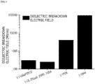
- the larger the band gap and maximum phonon frequency are, the larger the electric field (F b ) when dielectric breakdown occurs is, and thus, the thickness of the coating layer for blocking the movement of electrons may be reduced.
- a breakdown electric field is predicted by analyzing the maximum phonon cutoff frequency, and a minimum coating thickness, at which dielectric breakdown does not occur under charge and discharge conditions, is determined therefrom. Accordingly, the oxidation/reduction reaction at the interface between the positive electrode active material and the electrolyte solution may be suppressed by preventing breakdown due to electron tunneling effect.
- a positive electrode active material for a secondary battery includes:
- the coating layer has a band gap of 5.5 eV to 10 eV and includes at least one compound having lithium ion conductivity.
- the band gap is determined by a crystal structure of the compound, wherein the larger the band gap is, the higher the electron transfer resistance is, and thus, the thickness of the coating layer may be reduced.
- the thickness of the coating layer is excessively decreased when the band gap is excessively large, uniform coating is difficult, and thus, there is a concern that the active material and the electrolyte may be in contact with each other.
- the thickness of the coating layer is excessively increased when the band gap is excessively small, the coating layer itself may act as a resistance during the movement of lithium ions.
- the lithium ion conductive compound may specifically have a band gap of 5.5 eV to 10 eV, particularly 5.8 eV to 10 eV, and more particularly 6 eV to 10 eV.
- the band gap may be calculated by using a band gap measurement program, specifically, GW or HSE06 (Heyd-Scuseria-Ernzerhof).
- the lithium ion conductive compound may specifically have a lithium ion conductivity of 1 ⁇ 10 -8 S/cm to 1 ⁇ 10 -2 S/cm at 25°C.
- the lithium ion conductive compound may include at least one compound selected from the group consisting of lithium sulfide, lithium nitride, and lithium hydride. Since a high-temperature sintering process is not necessary for these compounds during the preparation of the active material, a process is simple and there is no concern about the occurrence of a side reaction due to high-temperature sintering. Furthermore, ionic conductivity is lower than that of a conventional oxide-based lithium ion conductive compound, but it is more advantageous in terms of energy density of the battery because the thickness of the coating layer may be reduced and density is low.
- the lithium sulfide may specifically include Li 10 GeP 2 S 12 , Li 3.25 Ge 0.25 P 0.75 S 4 , Li 2 S-P 2 S 5 -LiCl, Li 2 S-P 2 S 5 , Li 2 S-P 2 S 5 -LiI, Li 2 S-P 2 S 5 -Li 2 O, Li 2 S-P 2 S 5 -Li 2 O-LiI, Li 2 S-SiS 2 , Li 2 S-SiS 2 -LiI, Li 2 S-SiS 2 -LiBr, Li 2 S-SiS 2 -LiCl, Li 2 S-SiS 2 -B 2 S 3 -LiI, Li 2 S-SiS 2 -P 2 S 5 -LiI, Li 2 S-B 2 S 3 , Li 2 S-P 2 S 5 -X 1 a S b (where a and b are each independently an integer of 1 or more, and
- the lithium nitride may include Li 2 PO 2 N; or a Li e PO f N g -based compound (where 2.6 ⁇ e ⁇ 3.0, 3.0 ⁇ f ⁇ 4.0, and 0.1 ⁇ g ⁇ 0.6), such as Li 2.9 PO 3.3 N 0.46 , and any one thereof or a mixture of two or more thereof may be used.
- the lithium hydride may include LiBH 4 , LiBH 4 -LiI, or Li 2 NH.
- the lithium ion conductive compound may be selected from the group consisting of Li 2 PO 2 N, LiBH 4 , LiBH 4 -LiI, and Li 2 NH.
- the lithium ion conductive compound may affect the energy density of the active material. Accordingly, in consideration of the significant improvement due to the formation of the coating layer, the lithium ion conductive compound may have a density of 0.5 g/cm 3 or more, for example, 0.5 g/cm 3 or more to 2.5 g/cm 3 or less, which is lower than density of a typical oxide-based lithium ion conductive compound, under conditions satisfying the above-described band gap and ion conductive conditions.
- the lithium ion conductive compound since the lithium ion conductive compound has low density, it is more advantageous in terms of the energy density of the battery in comparison to the oxide-based lithium ion conductive compound.
- the lithium ion conductive compound may be lithium nitride or lithium hydride having a band gap of 8 eV to 10 eV and a density of 0.5 g/cm 3 to 2.5 g/cm 3 .
- the band gap, ion conductivity, and density of the above-described lithium ion conductive compound may be achieved by controlling components constituting the lithium ion conductive compound, content ratio, and crystal structure.
- the thickness (d) of the coating layer including the above-described lithium ion conductive compound may satisfy X ⁇ d ⁇ 100X.
- X is a maximum distance at which electrons may pass through the coating layer by a dielectric breakdown electric field when charging to an open circuit voltage of the lithium composite metal oxide versus lithium, wherein it denotes a minimum distance limit to prevent the movement of electrons in the coating layer at the same voltage.
- X V / F b in Equation 1
- V is the open circuit voltage of the lithium composite metal oxide versus lithium
- F b is a dielectric breakdown electric field value calculated by Equation 2 below
- F b 24.442 exp 0.315 E g ⁇ max in Equation 2
- E g is a band gap
- ⁇ max is the maximum phonon frequency.
- the thickness (d) may satisfy X ⁇ d ⁇ X b (where X b is the thickness of the coating layer when bulk resistance of the coating layer calculated by the following Equation 3 is 10 ⁇ ).
- Bulk resistance of the coating layer lithium ion conductivity of the lithium ion conductive compound ⁇ the thickness of the coating layer
- the bulk resistance of the coating layer is 10 ⁇ or more, it is not desirable because output characteristics during the operation of a cell are low due to the large resistance.
- FIG. 1 is a graph illustrating breakdown electric fields of various lithium ion conductive compounds which may be used in the present invention
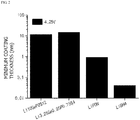
- FIG. 2 is a graph illustrating minimum coating thicknesses during the formation of coating layers on cores including a lithium composite metal oxide, LiCoO 2 , using various lithium ion conductive compounds.
- DFT-GGA density-functional theory
- DFPT density functional perturbation theory
- the thickness of the coating layer calculated by Equations 1 and 2 may be less than 500 nm, particularly 300 nm or less, and more particularly in a range of 1 nm to 100 nm.
- the coating layer has the above-described thickness, the breakdown due to the electron tunneling effect may be prevented while minimizing the resistance of the coating layer itself, and, accordingly, the oxidation/reduction reaction at the interface between the active material and the electrolyte solution may be suppressed.
- the thickness of the coating layer denotes an average thickness and may be measured by particle section analysis using a forced ion beam (FIB) .
- FIB forced ion beam
- FIG. 1 is a graph illustrating breakdown electric fields of various lithium ion conductive compounds which may be used in the present invention
- FIG. 2 is a graph illustrating minimum coating thicknesses during the formation of coating layers on cores including a lithium composite metal oxide, LiCoO 2 , using various lithium ion conductive compounds.
- DFT-GGA density-functional theory
- DFPT density functional perturbation theory
- the core may be a single particulate primary structure including the lithium composite metal oxide, or a secondary structure formed by agglomeration of two or more particulate primary structures.
- the expression “primary structure” denotes a single-particle structure
- the expression “secondary structure” denotes an aggregate in which the primary structures are agglomerated each other by physical or chemical bonding between the primary structures without an intentional agglomeration or assembly process for the primary structures constituting the secondary structure.
- the lithium composite metal oxide is a compound (lithiated intercalation compound) capable of reversibly intercalating and deintercalating lithium, wherein a lithium composite metal oxide including lithium and at least one metal, such as cobalt, manganese, nickel, or aluminum, may be specifically included.
- the lithium composite metal oxide may include lithium-manganese-based oxide (e.g., LiMnO 2 , LiMn 2 O 4 , etc.), lithium-cobalt-based oxide (e.g., LiCoO 2 , etc.), lithium-nickel-based oxide (e.g., LiNiO 2 , etc.), lithium-nickel-manganese-based oxide (e.g., LiNi 1-h Mn h O 2 (where 0 ⁇ h ⁇ 1), LiMn 2-1 Ni i O 4 (where 0 ⁇ i ⁇ 2), etc.), lithium-nickel-cobalt-based oxide (e.g., LiNi 1-j Co j O 2 (where 0 ⁇ j ⁇ 1), lithium-manganese-cobalt-based oxide (e.g., LiCo 1-k Mn k O 2 (where 0 ⁇ k ⁇ 1), LiMn 2 - l Co l O 4 (where 0 ⁇ l ⁇ 2), etc.), lithium-nickel
- At least one metallic element other than lithium in the lithium composite metal oxide may be doped with at least one element selected from the group consisting of Al, Cu, Fe, V, Cr, Ti, Zr, Zn, In, Ta, yttrium (Y), lanthanum (La), strontium (Sr), Ga, scandium (Sc), gadolinium (Gd), samarium (Sm), calcium (Ca), cerium (Ce), Nb, Mg, B, W, and Mo.
- the lithium composite metal oxide with lithium defects is further doped with the above-described metallic element, structural stability of the positive electrode active material may be improved, and, as a result, the output characteristics of the battery may be improved.
- an amount of the doping element included in the lithium composite metal oxide may be appropriately adjusted within a range that does not degrade characteristics of the positive electrode active material, and may specifically be 0.02 at% or less.
- the lithium composite metal oxide may include a compound of Formula 1 below.
- Formula 1 Li ⁇ Ni 1- ⁇ - ⁇ Co ⁇ M1 ⁇ M2 ⁇ O 2
- M1 includes at least one element selected from the group consisting of Al and manganese (Mn)
- M2 includes at least one element selected from the group consisting of Al, Cu, Fe, V, Cr, Ti, Zr, Zn, In, Ta, Y, La, Sr, Ga, Sc, Gd, Sm, Ca, Ce, Nb, Mg, B, W, and Mo, but M1 and M2 are different elements from each other, wherein 1.0 ⁇ 1.5, 0 ⁇ 0.5, 0 ⁇ 0.5, 0 ⁇ 0.02, and 0 ⁇ + ⁇ 0.4, for example, 1.0 ⁇ 1.2, 0 ⁇ 0.5, 0 ⁇ 0.5, 0.0005 ⁇ 0.02, and 0 ⁇ + ⁇ 0.4.
- ⁇ is a value when it is uncharged
- a composition of Formula 1 is an average value.
- the lithium composite metal oxide may include LiCoO 2 , LiMnO 2 , LiNiO 2 , lithium nickel manganese cobalt oxide (e.g., Li(Ni 0.6 Mn 0.2 Co 0.2 )O 2 , LiNi 0.5 Mn 0.3 Co 0.2 O 2 , LiNi 0.7 Mn 0.15 Co 0.15 O 2 , or LiNi 0.8 Mn 0.1 Co 0.1 O 2 ), or lithium nickel cobalt aluminum oxide (e.g., LiNi 0.8 Co 0.15 Al 0.05 O 2 , etc.), and, in consideration of significant improvement due to the control of type and content ratio of elements constituting the lithium composite metal oxide, the lithium composite metal oxide may include LiNi 0.6 Mn 0.2 Co 0.2 O 2 , LiNi 0.5 Mn 0.3 Co 0.2 O 2 , LiNi 0.7 Mn 0.15 Co 0.15 O 2 , or LiNi 0.8 Mn 0.1 Co 0.1
- the primary structure including the lithium composite metal oxide may have an average particle diameter (D 50 ) of 50 nm to 1,000 nm, for example, 100 nm to 500 nm.
- D 50 average particle diameter
- the average particle diameter of the primary structure is less than 50 nm, dispersibility may be low due to strong cohesion between the primary structures, and it may be difficult to include the lithium ion conductive compound at an interface between the primary structures during the preparation of the active material.
- the average particle diameter of the primary structure is greater than 1,000 nm, the disersibility of the primary structure itself may be low, and pores in the structure may be excessively enlarged during the formation of the secondary structure.
- the positive electrode active material including the secondary structure formed by the agglomeration of the above-described primary structures may have an average particle diameter (D 50 ) of 1 ⁇ m to 20 ⁇ m in consideration of specific surface area and positive electrode material mixture density.
- the average particle diameter of the positive electrode active material is less than 1 ⁇ m, there is a concern that dispersibility in the positive electrode material mixture may be reduced due to the agglomeration of the positive electrode active material, and, in a case in which the average particle diameter of the positive electrode active material is greater than 20 ⁇ m, there is a concern that mechanical strength and specific surface are of the positive electrode active material may be reduced.
- the positive electrode active material may have an average particle diameter (D 50 ) of 1 ⁇ m to 15 ⁇ m in consideration of significant improvement in rate capability and initial capacity characteristics of the battery due to the control of the particle diameter of the positive electrode active material.
- the average particle diameters (D 50 ) of the primary structure and the secondary structure of the positive electrode active material may each be defined as a particle diameter at 50% in a cumulative particle diameter distribution.
- the average particle diameters (D 50 ) of the primary structure and the secondary structure may be measured by using a laser diffraction method.
- the average particle diameter (D 50 ) of the positive electrode active material after particles of the positive electrode active material are dispersed in a dispersion medium, the dispersion medium is introduced into a commercial laser diffraction particle size measurement instrument (e.g., Microtrac MT 3000) and irradiated with ultrasonic waves having a frequency of about 28 kHz and an output of 60 W, and the average particle diameter (D 50 ) at 50% in a cumulative particle diameter distribution of the measurement instrument may then be calculated.
- a commercial laser diffraction particle size measurement instrument e.g., Microtrac MT 3000
- the positive electrode active material according to the embodiment of the present invention may further include pores disposed in an air gap between the primary structures in the secondary structure.
- the pores may facilitate the penetration of the electrolyte solution into the active material to increase the contact interface between the active material and the electrolyte solution, and, as a result, the pores may further improve battery characteristics by facilitating the lithium ion movement from the electrolyte solution into the active material.
- the positive electrode active material may have a porosity of 1 vol% to 10 vol%, for example, 1 vol% to 5 vol%, based on a total volume of the positive electrode active material.
- the porosity of the positive electrode active material may be measured by using a pore distribution measurement method such as porosimetry, such as mercury porosimetry, or a gas adsorption method such as a Brunauer-Emmett-Teller (BET) method.
- a pore distribution measurement method such as porosimetry, such as mercury porosimetry
- a gas adsorption method such as a Brunauer-Emmett-Teller (BET) method.
- the positive electrode active material according to the embodiment of the present invention may have a BET specific surface area of 0.5 m 2 /g to 1.9 m 2 /g.
- the BET specific surface area of the positive electrode active material is greater than 1.9 m 2 /g, dispersion of the positive electrode active material in an active material layer may be reduced and resistance in an electrode may be increased due to the agglomeration of the positive electrode active material, and, in a case in which the BET specific surface area is less than 0.5 m 2 /g, the dispersion of the positive electrode active material itself may be reduced and the capacity may be reduced.
- the specific surface area of the positive electrode active material is measured by a Brunauer-Emmett-Teller (BET) method, wherein, specifically, the specific surface area may be calculated from a nitrogen gas adsorption amount at a liquid nitrogen temperature (77K) using BELSORP-mini II by Bell Japan Inc.
- BET Brunauer-Emmett-Teller
- the positive electrode active material according to the embodiment of the present invention satisfies the above-described average particle diameter and BET specific surface area conditions at the same time, excellent capacity and charge and discharge characteristics may be obtained.
- the positive electrode active material may have an average particle diameter (D 50 ) of 3 ⁇ m to 15 ⁇ m and a BET specific surface area of 1.0 m 2 /g to 1.5 m 2 /g.
- the positive electrode active material according to the embodiment of the present invention may have a tap density of 1.7 g/cc or more or 1.7 g/cc to 2.5 g/cc.
- the positive electrode active material of the present invention may exhibit high capacity characteristics by having high tap density within the above-described range.
- the tap density of the positive electrode active material may be measured by using a typical tap density meter, and may be specifically measured by using TAP-2S by LOGAN Instruments Corp.
- the positive electrode active material having the above-described configuration and structure according to the embodiment of the present invention may be prepared by a preparation method including a step of forming a film-shaped coating layer on a core including a lithium composite metal oxide using a lithium ion conductive compound having a band gap of 5.5 eV to 10 eV.
- the lithium ion conductive compound includes at least one selected from the group consisting of lithium sulfide, lithium nitride, and lithium hydride under conditions satisfying the above-described band gap conditions, and the formation of the coating layer may be performed such that the thickness of the film-shaped coating layer formed is lower than a value, at which dielectric breakdown does not occur at a breakdown electric field, calculated by Equation 1 when charging to an open circuit voltage of the lithium composite metal oxide versus lithium.
- a method of preparing the above-described positive electrode active material is provided.
- the core including the lithium composite metal oxide is the same as described above, and may be prepared by a typical method of preparing a lithium composite metal oxide.
- the core may be prepared by a method in which metallic raw materials including at least one metal, such as cobalt, manganese, nickel, or aluminum, are dry-mixed together and then heat-treated, or by a method in which, after metallic raw materials are mixed in water or a mixed solvent of water and an organic solvent (specifically, alcohol etc.) which may be uniformly mixed with the water, an ammonium cation-containing complexing agent, such as NH 4 OH and (NH 4 ) 2 SO 4 , and a basic compound, such as NaOH or KOH, are added thereto to perform a co-precipitation reaction, the reaction product is mixed with a lithium raw material, such as Li 2 CO 3 and LiOH, and a heat treatment is then performed.
- metallic raw materials including at least one metal such as cobalt, manganese, nickel, or aluminum
- an organic solvent specifically, alcohol etc
- the coating layer may be prepared by a dry or wet method.
- a uniform film-shaped coating layer may be formed on a surface of the core by surface-treating the core with a composition, which is prepared by dispersing the lithium ion conductive compound in a solvent, using a conventional slurry coating method, such as coating, dipping, and spraying, and then heat-treating the coated composition.
- the solvent which may be used in the preparation of the composition, may include water, an alcohol having 1 to 8 carbon atoms (e.g., methanol, ethanol, or isopropyl alcohol), or a polar organic solvent, such as dimethyl sulfoxide (DMSO), N-methylpyrrolidone (NMP), and acetone, and any one thereof or a mixture of two or more thereof may be used.
- DMSO dimethyl sulfoxide
- NMP N-methylpyrrolidone
- acetone any one thereof or a mixture of two or more thereof may be used.
- the above-described solvent may be included in an amount such that the composition may have appropriate coating properties during the surface treatment and may be easily removed during the subsequent heat treatment.
- the heat treatment after the surface treatment may be performed in a temperature range in which the solvent used in the composition may be removed. Specifically, the heat treatment may be performed in a temperature range of 100°C to 250°C. In a case in which the temperature during the heat treatment is less than 100°C, a side reaction may occur due to the residual solvent component and the battery characteristics may be degraded due to the side reaction. In a case in which the temperature during the heat treatment is greater than 250°C, a side reaction may occur due to high heat.
- the heat treatment may be performed in a temperature range of 180°C to 250°C in consideration of coating layer forming efficiency.
- a uniform film-shaped coating layer may be formed on the surface of the core by performing a heat treatment at a temperature of 600°C to 850°C after the mixing of the core and the lithium ion conductive compound.
- the temperature during the heat treatment is less than 600°C, the formation of the coating layer is insignificant, and, in a case in which the temperature during the heat treatment is greater than 850°C, degeneration of the positive electrode active material and the lithium ion conductive compound may occur and a side reactant may be formed due to over-sintering.
- the heat treatment process may be performed in a temperature range of 700°C to 850°C.
- a coating layer including the lithium ion conductive compound may be deposited on the surface of the core using a sputtering apparatus.
- operating conditions for example, pressure and temperature conditions, of the sputtering apparatus may be used without particular limitation as long as they are within pressure and temperature ranges used during the operation of a typical sputtering apparatus.
- the heat treatment process may be performed in multiple stages within the above-described temperature range, and, in this case, the heat treatment process may be performed by variously changing the temperature according to each stage.
- an atmosphere during the heat treatment is not particularly limited, but the heat treatment may be performed in a vacuum, inert, or air atmosphere. Also, the heat treatment process may be performed for 5 hours to 48 hours or 10 hours to 20 hours under the above-described conditions.
- the lithium ion conductive compound may be used in an amount such that the coating layer of the finally-prepared active material satisfies the above-described thickness conditions.
- the encapsulated coating layer in which the lithium ion conductive compound surrounds the entire surface of the core including the lithium composite metal oxide, is formed to the optimum thickness, the breakdown due to the electron tunneling effect may be prevented while minimizing the resistance of the coating layer itself, and thus, the oxidation/reduction reaction at the interface between the active material and the electrolyte solution may be suppressed.
- a positive electrode and a lithium secondary battery which include the above-described positive electrode active material.
- the positive electrode includes a positive electrode collector and a positive electrode active material layer formed on the positive electrode collector and including the above-described positive electrode active material.
- the positive electrode collector is not particularly limited as long as it has conductivity without causing adverse chemical changes in the battery, and, for example, stainless steel, aluminum, nickel, titanium, fired carbon, or aluminum or stainless steel that is surface-treated with one of carbon, nickel, titanium, silver, or the like may be used. Also, the positive electrode collector may typically have a thickness of 3 ⁇ m to 500 ⁇ m, and microscopic irregularities may be formed on the surface of the collector to improve the adhesion of the positive electrode active material.
- the positive electrode collector for example, may be used in various shapes such as that of a film, a sheet, a foil, a net, a porous body, a foam body, a non-woven fabric body, and the like.
- the positive electrode active material layer may selectively further include at least one of a conductive agent and a binder, if necessary, in addition to the above-described positive electrode active material.
- the positive electrode active material layer may be included in an amount of 80 wt% to 99 wt%, for example, 85 wt% to 98 wt%, based on a total weight of the positive electrode active material layer.
- the positive electrode active material may exhibit excellent capacity characteristics.
- the conductive agent is used to provide conductivity to the electrode, wherein any conductive agent may be used without particular limitation as long as it has suitable electron conductivity without causing adverse chemical changes in the battery.
- the conductive agent may be graphite such as natural graphite or artificial graphite; carbon based materials such as carbon black, acetylene black, Ketjen black, channel black, furnace black, lamp black, thermal black, and carbon fibers; powder or fibers of metal such as copper, nickel, aluminum, and silver; conductive whiskers such as zinc oxide whiskers and potassium titanate whiskers; conductive metal oxides such as titanium oxide; or conductive polymers such as polyphenylene derivatives, and any one thereof or a mixture of two or more thereof may be used.
- the conductive agent may be included in an amount of 1 wt% to 30 wt% based on the total weight of the positive electrode active material layer.
- the binder improves the adhesion between the positive electrode active material particles and the adhesion between the positive electrode active material and the current collector.
- the binder may be polyvinylidene fluoride (PVDF), a polyvinylidene fluoride-hexafluoropropylene copolymer (PVDF-co-HFP), polyvinyl alcohol, polyacrylonitrile, carboxymethyl cellulose (CMC), starch, hydroxypropyl cellulose, regenerated cellulose, polyvinylpyrrolidone, tetrafluoroethylene, polyethylene, polypropylene, an ethylene-propylene-diene monomer (EPDM), a sulfonated EPDM, a styrene-butadiene rubber (SBR), a fluorine rubber, or various copolymers thereof, and any one thereof or a mixture of two or more thereof may be used.
- the binder may be included in an amount of 1 wt% to 30 wt%
- the positive electrode may be prepared according to a typical method of preparing a positive electrode except that the above-described positive electrode active material is used. Specifically, a composition for forming a positive electrode active material layer, which is prepared by dispersing or dissolving the positive electrode active material as well as at least one of the binder and the conductive agent, if necessary, in a solvent, is coated on the positive electrode collector, and the positive electrode may then be prepared by drying and rolling the coated positive electrode collector. In this case, types and amounts of the positive electrode active material, the binder, and the conductive are the same as those previously described.
- the solvent may be a solvent normally used in the art.
- the solvent may include dimethyl sulfoxide (DMSO), isopropyl alcohol, N-methylpyrrolidone (NMP), acetone, or water, and any one thereof or a mixture of two or more thereof may be used.
- An amount of the solvent used may be sufficient if the solvent may dissolve or disperse the positive electrode active material, the conductive agent, and the binder in consideration of a coating thickness of a slurry and manufacturing yield, and may allow to have a viscosity that may provide excellent thickness uniformity during the subsequent coating for the preparation of the positive electrode.
- the positive electrode may be prepared by casting the composition for forming a positive electrode active material layer on a separate support and then laminating a film separated from the support on the positive electrode collector.
- an electrochemical device including the positive electrode is provided.
- the electrochemical device may specifically be a battery or a capacitor, and, for example, may be a lithium secondary battery.
- the lithium secondary battery specifically includes a positive electrode, a negative electrode disposed to face the positive electrode, a separator disposed between the positive electrode and the negative electrode, and an electrolyte, wherein the positive electrode is the same as described above. Also, the lithium secondary battery may further selectively include a battery case accommodating an electrode assembly of the positive electrode, the negative electrode, and the separator, and a sealing member sealing the battery case.
- the negative electrode includes a negative electrode collector and a negative electrode active material layer disposed on the negative electrode collector.
- the negative electrode collector is not particularly limited as long as it has high conductivity without causing adverse chemical changes in the battery, and, for example, copper, stainless steel, aluminum, nickel, titanium, fired carbon, copper or stainless steel that is surface-treated with one of carbon, nickel, titanium, silver, or the like, and an aluminum-cadmium alloy may be used.
- the negative electrode collector may typically have a thickness of 3 ⁇ m to 500 ⁇ m, and, similar to the positive electrode collector, microscopic irregularities may be formed on the surface of the collector to improve the adhesion of a negative electrode active material.
- the negative electrode collector for example, may be used in various shapes such as that of a film, a sheet, a foil, a net, a porous body, a foam body, a non-woven fabric body, and the like.
- the negative electrode active material layer selectively includes a binder and a conductive agent in addition to the negative electrode active material.
- the negative electrode active material layer may be prepared by coating a composition for forming a negative electrode, which selectively includes the binder and the conductive agent as well as the negative electrode active material, on the negative electrode collector and drying the coated negative electrode collector, or may be prepared by casting the composition for forming a negative electrode on a separate support and then laminating a film separated from the support on the negative electrode collector.
- Any negative electrode active material may be used as the negative electrode active material without limitation as long as it is a compound capable of reversibly intercalating and deintercalating lithium and is used in the art.
- the negative electrode active material may include a carbonaceous material such as artificial graphite, natural graphite, graphitized carbon fibers, and amorphous carbon; a metallic compound alloyable with lithium such as Si, Al, tin (Sn), lead (Pb), Zn, bismuth (Bi), In, Mg, Ga, cadmium (Cd), a Si alloy, a Sn alloy, or an Al alloy; a metal oxide which may be doped and undoped with lithium such as SiO ⁇ (0 ⁇ 2), SnO 2 , vanadium oxide, and lithium vanadium oxide; or a composite including the metallic compound and the carbonaceous material such as a Si-C composite or a Sn-C composite, and any one thereof or a mixture of two or more thereof may be used.
- a carbonaceous material such as artificial graphite, natural graphite, graphitized carbon fibers, and amorphous carbon
- a metallic compound alloyable with lithium such as Si, Al, tin (Sn), lead
- both low crystalline carbon and high crystalline carbon may be used as the carbon material.
- Typical examples of the low crystalline carbon may be soft carbon and hard carbon
- typical examples of the high crystalline carbon may be irregular, planar, flaky, spherical, or fibrous natural graphite or artificial graphite, Kish graphite, pyrolytic carbon, mesophase pitch-based carbon fibers, meso-carbon microbeads, mesophase pitches, and high-temperature sintered carbon such as petroleum or coal tar pitch derived cokes.
- a metallic lithium thin film may be used as the negative electrode active material.
- the metallic lithium thin film not only has a high ionization tendency, a small atomic weight, and low density, but also has a very low standard electrode potential, and thus, the metallic lithium thin film may have high specific capacity. Accordingly, in a case in which the metallic lithium thin film is used, a negative electrode having high energy density may be prepared.
- the battery having high capacity characteristics may be prepared when the negative electrode is used in the battery.
- the binder and the conductive agent may be the same as those previously described in the positive electrode.
- the separator separates the negative electrode and the positive electrode and provides a movement path of lithium ions
- any separator may be used as the separator without particular limitation as long as it is typically used as a separator in a lithium secondary battery, and particularly, a separator having high moisture-retention ability for an electrolyte as well as low resistance to the transfer of electrolyte ions may be used.
- a porous polymer film for example, a porous polymer film prepared from a polyolefin-based polymer, such as an ethylene homopolymer, a propylene homopolymer, an ethylene/butene copolymer, an ethylene/hexene copolymer, and an ethylene/methacrylate copolymer, or a laminated structure having two or more layers thereof may be used.
- a typical porous nonwoven fabric for example, a nonwoven fabric formed of high melting point glass fibers or polyethylene terephthalate fibers may be used.
- a coated separator including a ceramic component or a polymer material may be used to secure heat resistance or mechanical strength, and the separator having a single layer or multilayer structure may be selectively used.
- the electrolyte used in the present invention may include an organic liquid electrolyte, an inorganic liquid electrolyte, a solid polymer electrolyte, a gel-type polymer electrolyte, a solid inorganic electrolyte, or a molten-type inorganic electrolyte which may be used in the preparation of the lithium secondary battery, but the present invention is not limited thereto.
- the electrolyte may include an organic solvent and a lithium salt.
- any organic solvent may be used as the organic solvent without particular limitation so long as it may function as a medium through which ions involved in an electrochemical reaction of the battery may move.
- an ester-based solvent such as methyl acetate, ethyl acetate, ⁇ -butyrolactone, ⁇ -caprolactone, propyl acetate, methyl propionate, ethyl propionate, propyl propionate, and butyl propionate
- an ether-based solvent such as dimethoxyethane, diethoxyethane, dibutyl ether, or tetrahydrofuran
- a ketone-based solvent such as cyclohexanone
- an aromatic hydrocarbon-based solvent such as benzene and fluorobenzene
- a carbonate-based solvent such as dimethyl carbonate (DMC), diethyl carbonate (DEC), methylethyl carbonate (MEC), ethylmethyl carbonate (EMC), ethylene
- a passivation layer may be formed on a surface of the negative electrode by a spontaneous reaction when the lithium metal and the electrolyte component are in contact with each other. That is, since the formation and removal of the passivation layer formed on the surface of the negative electrode are repeated during charge and discharge of the secondary battery, the passivation layer component in the lithium negative electrode may be increased and the electrolyte may be depleted when the charge and discharge of the battery are repeated. Also, since some converted materials in the electrolyte cause a side reaction with the lithium metal, lithium consumption rate may be increased.
- the ether-based solvent having a lower oxidation potential than lithium since the ether-based solvent has a lower ionization tendency than the lithium, the reactivity with the lithium is reduced, and thus, lithium consumption may be delayed.
- the lithium salt may be used without particular limitation as long as it is a compound capable of providing lithium ions used in the lithium secondary battery. Specifically, LiPF 6 , LiClO 4 , LiAsF 6 , LiBF 4 , LiSbF 6 , LiAlO 4 , LiAlCl 4 , LiCF 3 SO 3 , LiC 4 F 9 SO 3 , LiN(C 2 F 5 SO 3 ) 2 , LiN(C 2 F 5 SO 2 ) 2 , LiN(CF 3 SO 2 ) 2 , LiCl, LiI, or LiB(C 2 O 4 ) 2 may be used as the lithium salt.
- the lithium salt may be used in a concentration range of 0.1 M to 2.0 M. In a case in which the concentration of the lithium salt is included within the above range, since the electrolyte may have appropriate conductivity and viscosity, excellent performance of the electrolyte may be obtained and lithium ions may effectively move.
- At least one additive for example, a halo-alkylene carbonate-based compound such as difluoroethylene carbonate, pyridine, triethylphosphite, triethanolamine, cyclic ether, ethylenediamine, n-glyme, hexaphosphoric triamide, a nitrobenzene derivative, sulfur, a quinone imine dye, N-substituted oxazolidinone, N,N-substituted imidazolidine, ethylene glycol dialkyl ether, an ammonium salt, pyrrole, 2-methoxy ethanol, or aluminum trichloride, may be further added to the electrolyte in addition to the electrolyte components.
- the additive may be included in an amount of 0.1 wt% to 5 wt% based on a total weight of the electrolyte.
- the lithium secondary battery including the positive electrode active material according to the present invention stably exhibits excellent discharge capacity, output characteristics, and capacity retention
- the lithium secondary battery is suitable for portable devices, such as mobile phones, notebook computers, and digital cameras, and electric cars such as hybrid electric vehicles (HEVs).
- portable devices such as mobile phones, notebook computers, and digital cameras
- electric cars such as hybrid electric vehicles (HEVs).
- HEVs hybrid electric vehicles
- a battery module including the lithium secondary battery as a unit cell and a battery pack including the battery module are provided.
- the battery module or the battery pack may be used as a power source of at least one medium and large sized device of a power tool; electric cars including an electric vehicle (EV), a hybrid electric vehicle, and a plug-in hybrid electric vehicle (PHEV); or a power storage system.
- electric cars including an electric vehicle (EV), a hybrid electric vehicle, and a plug-in hybrid electric vehicle (PHEV); or a power storage system.
- EV electric vehicle
- PHEV plug-in hybrid electric vehicle
- X V / F b in Equation 1
- V is an open circuit voltage of the lithium composite metal oxide versus lithium
- F b is a dielectric breakdown electric field value calculated by Equation 2 below
- F b 24.442 exp 0.315 E g ⁇ max in Equation 2
- E g is a band gap
- ⁇ max is the maximum phonon frequency.
- a coating layer was formed on LiCoO 2 by sputtering a Li 3 PO 4 target for 1 minute in a vacuum chamber in an argon (Ar) atmosphere. It was confirmed that a thickness of the surface coating layer was adjusted according to deposition time. In this case, the thickness of the coating layer formed on the surface was checked by using a scanning electron microscope.
- a positive electrode active material was prepared in which a 1 nm thick Li 2 PO 2 N coating layer was formed on the surface of LiCoO 2 .
- the above-prepared positive electrode active material, a carbon black conductive agent, and a polyvinylidene fluoride (PVDF) binder were mixed in an N-methylpyrrolidone solvent at a weight ratio of 95:2.5:2.5 to prepare a composition for forming a positive electrode (viscosity: 5,000 mPs).
- a 20 ⁇ m thick aluminum current collector was coated with the composition for forming a positive electrode, dried at 130°C, and then rolled to prepare a positive electrode.
- a 20 ⁇ m thick lithium metal electrode was stacked on a 10 ⁇ m thick copper current collector to be used as a negative electrode.
- a lithium secondary battery was prepared by preparing an electrode assembly by disposing a porous polyethylene separator between the positive electrode and the negative electrode prepared as described above, putting the electrode assembly in a case, and then injecting an electrolyte solution, in which 3 M lithium bis(fluorosulfonyl)imide (LiFSI) was dissolved in a dimethoxyethane solvent, into the case.
- LiFSI lithium bis(fluorosulfonyl)imide
- a coating layer was formed on LiNi 0.8 Mn 0.1 Co 0.1 O 2 by using a Li 3 PO 4 target in a vacuum chamber in an Ar atmosphere.
- a positive electrode and a lithium secondary battery, which include a positive electrode active material, were prepared in the same manner as in Example 1 except that the positive electrode active material having a 1 nm thick Li 2 PO 2 N coating layer formed on the surface thereof was prepared by setting the deposition time to 1 minute.
- Comparative Examples 2 and 3 in which the coating layers were respectively formed to thicknesses of 500 nm and 800 nm on the surfaces of the cores, were compared with Examples 1 to 3, it may be confirmed that internal resistance increase rates of Comparative Examples 2 and 3 were at equivalent levels to those of Examples 1 to 3 or lower than those of Examples 1 to 3.
- Comparative Examples 6 and 7 in which the coating layers were respectively formed to thicknesses of 500 nm and 800 nm on the surfaces of the cores, were compared with Examples 4 to 6, it may be confirmed that internal resistance increase rates of Comparative Examples 6 and 7 were at equivalent levels to those of Examples 4 to 6 or lower than those of Examples 4 to 6. The reason for this was that, as in Comparative Examples 2, 3, 6, and 7, since the side reaction between the positive electrode active material and the electrolyte solution was suppressed as the thickness of the coating layer was increased, the internal resistance was reduced.
- Comparative Examples 4 and 8 in which the surface of the core was coated with the layer in the form of islands, it may be confirmed that Comparative Examples 4 and 8 had higher internal resistance increase rates than Examples 1 to 6.
- the lithium secondary batteries prepared in Examples 1 to 6 and Comparative Examples 1 to 8 were maintained for 1 day at room temperature (25°C) and then charged at a constant current of 0.1 C to a voltage of 4.25 V. Thereafter, the lithium secondary batteries were discharged at a constant current of 0.1 C until the voltage reached 3.0 V to perform initial charge and discharge. In the subsequent charge and discharge, the lithium secondary batteries were charged at a constant current of 0.5 C to a voltage of 4.25 V, and discharged at a constant current of 0.5 C until the voltage reached 3.0 V. After the above charge and discharge cycle was set as one cycle and was repeated, a cycle, when residual capacity relative to initial discharge capacity was 80%, was recorded.
Landscapes
- Chemical & Material Sciences (AREA)
- Chemical Kinetics & Catalysis (AREA)
- Electrochemistry (AREA)
- General Chemical & Material Sciences (AREA)
- Engineering & Computer Science (AREA)
- Materials Engineering (AREA)
- Inorganic Chemistry (AREA)
- Manufacturing & Machinery (AREA)
- Composite Materials (AREA)
- Battery Electrode And Active Subsutance (AREA)
- Secondary Cells (AREA)
Abstract
Description
- This application claims the benefit of Korean Patent Application Nos.
10-2016-0128582, filed on October 5, 2016 10-2017-0125953, filed on September 28, 2017 - The present invention relates to a positive electrode active material for a secondary battery, which may improve energy density of an electrode and life characteristics of a battery and may prevent an oxidation/reduction reaction by blocking the movement of electrons at an interface between an active material and an electrolyte solution by a coating layer surrounding the surface of particles and having lithium ion conductivity, and a secondary battery including the same.
- Demand for secondary batteries as an energy source has been significantly increased as technology development and demand with respect to mobile devices have increased. Among these secondary batteries, lithium secondary batteries having high energy density, high voltage, long cycle life, and low self-discharging rate have been commercialized and widely used.
- However, lithium secondary batteries have a limitation in that lifetime rapidly decreases as charge and discharge are repeated, and the limitation is more serious in a long-life or high-voltage battery. Specifically, with respect to a LiMeO2-based lithium composite metal oxide (where Me is at least one of manganese (Mn), nickel (Ni), and cobalt (Co)) as a positive electrode active material for a high-voltage battery, degradation of a positive electrode occurs due to an oxidation/reduction reaction at an interface between an active material and an electrolyte solution or dissolution of the metallic element (Me) at a high voltage of 4 V (vs. Li/Li+) or more.
- In order to address the limitation, a method of coating the surface of the positive electrode active material with an inorganic material, such as Al2O3 or AlPO4, was proposed. However, since these inorganic materials had no lithium ion conductivity and were coated on the surface of particles in a crystalline state, it was difficult to uniformly coat the entire active material with the inorganic materials, and, as a result, it was difficult to sufficiently block the contact between the positive electrode active material and the electrolyte solution.
- Thus, there is an urgent need to develop a positive electrode active material which may improve performance of the lithium secondary battery while addressing the limitation.
- An aspect of the present invention provides a positive electrode active material for a secondary battery, which may improve energy density of an electrode and life characteristics of a battery and may prevent an oxidation/reduction reaction by blocking the movement of electrons at an interface between an active material and an electrolyte solution by a coating layer surrounding the surface of particles and having lithium ion conductivity, and a method of preparing the same.
- Another aspect of the present invention provides a positive electrode for a secondary battery and a lithium secondary battery which include the positive electrode active material.
- According to an aspect of the present invention, there is provided a positive electrode active material for a secondary battery including: a core including a lithium composite metal oxide; and a film-shaped coating layer disposed to surround the core,
wherein the coating layer includes at least one lithium ion conductive compound having a band gap of 5.5 eV to 10 eV, a thickness (d) of the coating layer satisfies X<d≤100X (where X is a maximum distance at which electrons are capable of passing through the coating layer by a dielectric breakdown electric field (Fb) when charging to an open circuit voltage of the lithium composite metal oxide versus lithium, wherein X is determined by Equation 1), wherein d is less than 500 nm, and
the lithium ion conductive compound includes at least one selected from the group consisting of lithium sulfide, lithium nitride, and lithium hydride:
wherein, in Equation 1, V is the open circuit voltage of the lithium composite metal oxide versus lithium, and Fb is a dielectric breakdown electric field value calculated by Equation 2, and
wherein, in Equation 2, Eg is a band gap, and ωmax is a maximum phonon frequency. - According to another aspect of the present invention, there is provided a method of preparing the above-described positive electrode active material for a secondary battery including forming a film-shaped coating layer on a core including a lithium composite metal oxide to a thickness (d) satisfying X<d≤100X (where X is the same as defined above), wherein the thickness (d) of the film-shaped coating layer is less than 500 nm, and the lithium ion conductive compound includes at least one selected from the group consisting of lithium sulfide, lithium nitride, and lithium hydride.
- According to another aspect of the present invention, there is provided a positive electrode for a secondary battery and a lithium secondary battery which include the above-described positive electrode active material.
- Details of other embodiments of the present invention are included in the following detailed description.
- In a positive electrode active material for a secondary battery according to the present invention, an oxidation/reduction reaction is suppressed by blocking the movement of electrons at an interface between an active material and an electrolyte solution by a film-shaped coating layer which surrounds the surface of particles and has lithium ion conductivity, and, as a result, the positive electrode active material may improve energy density of an electrode and life characteristics of a battery.
- The following drawings attached to the specification illustrate preferred examples of the present invention by example, and serve to enable technical concepts of the present invention to be further understood together with detailed description of the invention given below, and therefore the present invention should not be interpreted only with matters in such drawings.
-
FIG. 1 is a graph illustrating breakdown electric fields of various lithium ion conductive compounds; and -
FIG. 2 is a graph illustrating minimum coating thicknesses during the formation of coating layers using various lithium ion conductive compounds. - Hereinafter, the present invention will be described in more detail to allow for a clearer understanding of the present invention.
- It will be understood that words or terms used in the specification and claims shall not be interpreted as the meaning defined in commonly used dictionaries. It will be further understood that the words or terms should be interpreted as having a meaning that is consistent with their meaning in the context of the relevant art and the technical idea of the invention, based on the principle that an inventor may properly define the meaning of the words or terms to best explain the invention.
- Typically, in order to suppress a reaction at an interface between a positive electrode active material for a secondary battery and an electrolyte solution, a method of forming a coating layer on a surface of the positive electrode active material has been tried. However, since a conventional coating material used in the formation of the coating layer has no lithium ion conductivity and does not surround the entire surface of the positive electrode active material, the coating layer may not sufficiently suppress an oxidation/reduction reaction between the positive electrode active material and the electrolyte solution. Also, since the coating layer acts as a resistance as its thickness is increased, there is a need to optimize the thickness.
- In the present invention, the contact at the interface between the active material and the electrolyte solution may be blocked by forming a film-shaped encapsulated coating layer which surrounds the entire surface of the active material instead of grain boundaries. Also, since the coating layer is formed by using a compound having lithium ion conductivity, movement of lithium ions from the electrolyte solution in the coating layer may be possible. Furthermore, the larger the band gap and maximum phonon frequency are, the larger the electric field (Fb) when dielectric breakdown occurs is, and thus, the thickness of the coating layer for blocking the movement of electrons may be reduced. Therefore, after band gaps of coating materials are calculated through computational chemistry simulation, a breakdown electric field is predicted by analyzing the maximum phonon cutoff frequency, and a minimum coating thickness, at which dielectric breakdown does not occur under charge and discharge conditions, is determined therefrom. Accordingly, the oxidation/reduction reaction at the interface between the positive electrode active material and the electrolyte solution may be suppressed by preventing breakdown due to electron tunneling effect.
- Specifically, a positive electrode active material for a secondary battery according to an embodiment of the present invention includes:
- a core including a lithium composite metal oxide; and
- a film-shaped coating layer disposed to surround the core,
- wherein the coating layer includes at least one lithium ion conductive compound having a band gap of 5.5 eV to 10 eV, and has a thickness (d) satisfying X<d≤100X (where X is a maximum distance, at which electrons may pass through the coating layer by a dielectric breakdown electric field (Fb) when charging to an open circuit voltage of the lithium composite metal oxide versus lithium, and a minimum distance to prevent the movement of electrons in the coating layer, wherein X is determined by Equation 1), wherein the thickness (d) is less than 500 nm, and
- the lithium ion conductive compound includes at least one selected from the group consisting of lithium sulfide, lithium nitride, and lithium hydride:
- In the positive electrode active material for a secondary battery according to the embodiment of the present invention, the coating layer has a band gap of 5.5 eV to 10 eV and includes at least one compound having lithium ion conductivity.
- The band gap is determined by a crystal structure of the compound, wherein the larger the band gap is, the higher the electron transfer resistance is, and thus, the thickness of the coating layer may be reduced. However, since the thickness of the coating layer is excessively decreased when the band gap is excessively large, uniform coating is difficult, and thus, there is a concern that the active material and the electrolyte may be in contact with each other. Also, since the thickness of the coating layer is excessively increased when the band gap is excessively small, the coating layer itself may act as a resistance during the movement of lithium ions. Accordingly, in order to block the movement of electrons with a minimum thickness while not reducing lithium ion mobility, the lithium ion conductive compound may specifically have a band gap of 5.5 eV to 10 eV, particularly 5.8 eV to 10 eV, and more particularly 6 eV to 10 eV.
- In the present invention, after a structure of a measurement target compound is optimized by generalized gradient approximation (GGA) based on density-functional theory (DFT) (DFT-GGA(PBEsol), the band gap may be calculated by using a band gap measurement program, specifically, GW or HSE06 (Heyd-Scuseria-Ernzerhof).
- Also, as a compound capable of conducting lithium ions under conditions satisfying the above-described band gap conditions, the lithium ion conductive compound may specifically have a lithium ion conductivity of 1 × 10⁻⁸ S/cm to 1 × 10⁻² S/cm at 25°C. Specifically, the lithium ion conductive compound may include at least one compound selected from the group consisting of lithium sulfide, lithium nitride, and lithium hydride. Since a high-temperature sintering process is not necessary for these compounds during the preparation of the active material, a process is simple and there is no concern about the occurrence of a side reaction due to high-temperature sintering. Furthermore, ionic conductivity is lower than that of a conventional oxide-based lithium ion conductive compound, but it is more advantageous in terms of energy density of the battery because the thickness of the coating layer may be reduced and density is low.
- In the lithium ion conductive compound, the lithium sulfide may specifically include Li10GeP2S12, Li3.25Ge0.25P0.75S4, Li2S-P2S5-LiCl, Li2S-P2S5, Li2S-P2S5-LiI, Li2S-P2S5-Li2O, Li2S-P2S5-Li2O-LiI, Li2S-SiS2, Li2S-SiS2-LiI, Li2S-SiS2-LiBr, Li2S-SiS2-LiCl, Li2S-SiS2-B2S3-LiI, Li2S-SiS2-P2S5-LiI, Li2S-B2S3, Li2S-P2S5-X1 aSb (where a and b are each independently an integer of 1 or more, and X1 is any one selected from the group consisting of germanium (Ge), zinc (Zn), and gallium (Ga)), Li2S-GeS2, Li2S-SiS2-Li3PO4, or Li2S-SiS2-LicX2Od (where c and d are each independently an integer of 1 or more, and X2 is any one selected from the group consisting of phosphorus (P), silicon (Si), Ge, boron (B), aluminum (Al), Ga, and indium (In)), and any one thereof or a mixture of two or more thereof may be used.
- Also, the lithium nitride may include Li2PO2N; or a LiePOfNg-based compound (where 2.6≤e≤3.0, 3.0≤f≤4.0, and 0.1≤g≤0.6), such as Li2.9PO3.3N0.46, and any one thereof or a mixture of two or more thereof may be used.
- Furthermore, the lithium hydride may include LiBH4, LiBH4-LiI, or Li2NH.
- Among these compounds, in consideration of significant improvement due to the formation of the coating layer of the lithium ion conductive compound, the lithium ion conductive compound may be selected from the group consisting of Li2PO2N, LiBH4, LiBH4-LiI, and Li2NH.
- Also, density of the lithium ion conductive compound may affect the energy density of the active material. Accordingly, in consideration of the significant improvement due to the formation of the coating layer, the lithium ion conductive compound may have a density of 0.5 g/cm3 or more, for example, 0.5 g/cm3 or more to 2.5 g/cm3 or less, which is lower than density of a typical oxide-based lithium ion conductive compound, under conditions satisfying the above-described band gap and ion conductive conditions. Thus, since the lithium ion conductive compound has low density, it is more advantageous in terms of the energy density of the battery in comparison to the oxide-based lithium ion conductive compound.
- Among the above-described lithium ion conductive compounds, in consideration of excellent lithium ion conductivity and the suppression of the oxidation/reduction reaction at the interface with the electrolyte solution due to the formation of the coating layer, the lithium ion conductive compound may be lithium nitride or lithium hydride having a band gap of 8 eV to 10 eV and a density of 0.5 g/cm3 to 2.5 g/cm3.
- In the present invention, the band gap, ion conductivity, and density of the above-described lithium ion conductive compound may be achieved by controlling components constituting the lithium ion conductive compound, content ratio, and crystal structure.
- Furthermore, the thickness (d) of the coating layer including the above-described lithium ion conductive compound may satisfy X<d≤100X. In this case, X is a maximum distance at which electrons may pass through the coating layer by a dielectric breakdown electric field when charging to an open circuit voltage of the lithium composite metal oxide versus lithium, wherein it denotes a minimum distance limit to prevent the movement of electrons in the coating layer at the same voltage. X may be determined by Equation 1 below:

in Equation 1, V is the open circuit voltage of the lithium composite metal oxide versus lithium, and Fb is a dielectric breakdown electric field value calculated by Equation 2 below,
in Equation 2, Eg is a band gap, and ωmax is the maximum phonon frequency. - Specifically, the thickness (d) may satisfy X<d<Xb (where Xb is the thickness of the coating layer when bulk resistance of the coating layer calculated by the following Equation 3 is 10 Ω).

- If the bulk resistance of the coating layer is 10 Ω or more, it is not desirable because output characteristics during the operation of a cell are low due to the large resistance.
- In this regard,
FIG. 1 is a graph illustrating breakdown electric fields of various lithium ion conductive compounds which may be used in the present invention, andFIG. 2 is a graph illustrating minimum coating thicknesses during the formation of coating layers on cores including a lithium composite metal oxide, LiCoO2, using various lithium ion conductive compounds. In this case, batteries each including the positive electrode active material were charged at 4.25 V, the band gap is a value (unit eV) calculated by using a band gap measurement program after a structure of the corresponding lithium ion conductive compound is optimized by generalized gradient approximation based on density-functional theory (DFT-GGA), and the phonon frequency is a value (unit=THz) calculated using density functional perturbation theory (DFPT) and finite displacement implemented in the phonopy code. - The thickness of the coating layer calculated by Equations 1 and 2 may be less than 500 nm, particularly 300 nm or less, and more particularly in a range of 1 nm to 100 nm.
- When the coating layer has the above-described thickness, the breakdown due to the electron tunneling effect may be prevented while minimizing the resistance of the coating layer itself, and, accordingly, the oxidation/reduction reaction at the interface between the active material and the electrolyte solution may be suppressed.
- In the present invention, the thickness of the coating layer denotes an average thickness and may be measured by particle section analysis using a forced ion beam (FIB) .
- In this regard,
FIG. 1 is a graph illustrating breakdown electric fields of various lithium ion conductive compounds which may be used in the present invention, andFIG. 2 is a graph illustrating minimum coating thicknesses during the formation of coating layers on cores including a lithium composite metal oxide, LiCoO2, using various lithium ion conductive compounds. In this case, batteries each including the positive electrode active material are charged at 4.25 V, the band gap is a value (unit eV) calculated by using a band gap measurement program after a structure of the corresponding lithium ion conductive compound is optimized by generalized gradient approximation based on density-functional theory (DFT-GGA), and the phonon frequency is a value (unit=THz) calculated using density functional perturbation theory (DFPT) and finite displacement implemented in the phonopy code. In a case in which the thickness of the coating layer calculated by Equations 1 and 2 is less than the minimum coating thickness illustrated inFIG. 2 , the dielectric breakdown of the positive electrode active material due to the electron tunneling effect may occur. - In the positive electrode active material according to the embodiment of the present invention, the core may be a single particulate primary structure including the lithium composite metal oxide, or a secondary structure formed by agglomeration of two or more particulate primary structures.
- In the present invention, the expression "primary structure" denotes a single-particle structure, and the expression "secondary structure" denotes an aggregate in which the primary structures are agglomerated each other by physical or chemical bonding between the primary structures without an intentional agglomeration or assembly process for the primary structures constituting the secondary structure.
- The lithium composite metal oxide is a compound (lithiated intercalation compound) capable of reversibly intercalating and deintercalating lithium, wherein a lithium composite metal oxide including lithium and at least one metal, such as cobalt, manganese, nickel, or aluminum, may be specifically included.
- Specifically, the lithium composite metal oxide may include lithium-manganese-based oxide (e.g., LiMnO2, LiMn2O4, etc.), lithium-cobalt-based oxide (e.g., LiCoO2, etc.), lithium-nickel-based oxide (e.g., LiNiO2, etc.), lithium-nickel-manganese-based oxide (e.g., LiNi1-hMnhO2 (where 0<h<1), LiMn2-1NiiO4 (where 0<i<2), etc.), lithium-nickel-cobalt-based oxide (e.g., LiNi1-jCojO2 (where 0<j<1), lithium-manganese-cobalt-based oxide (e.g., LiCo1-kMnkO2 (where 0<k<1), LiMn2-lColO4 (where 0<l<2), etc.), lithium-nickel-manganese-cobalt-based oxide (e.g., Li(NimConMnp)O2 (where 0<m<1, 0<n<1, 0<p<1, and m+n+p=1) or Li(NiqCorMns)O4 (where 0<q<2, 0<r<2, 0<s<2, and q+r+s=2), etc.), or lithium-nickel-cobalt-metal(Me) oxide (e.g., Li(NitCouMnvMw)O2 (where Me includes at least one selected from the group consisting of aluminum (Al), copper (Cu), iron (Fe), vanadium (V), chromium (Cr), titanium (Ti), zirconium (Zr), zinc (Zn), tantalum (Ta), niobium (Nb), magnesium (Mg), boron (B), tungsten (W), and molybdenum (Mo), and t, u, v, and w are atomic fractions of each independent elements, wherein 0<t<1, 0<u<1, 0<v<1, 0<w<1, and t+u+v+w=1), etc.), and any one thereof or a compound of two or more thereof may be included.
- Also, at least one metallic element other than lithium in the lithium composite metal oxide may be doped with at least one element selected from the group consisting of Al, Cu, Fe, V, Cr, Ti, Zr, Zn, In, Ta, yttrium (Y), lanthanum (La), strontium (Sr), Ga, scandium (Sc), gadolinium (Gd), samarium (Sm), calcium (Ca), cerium (Ce), Nb, Mg, B, W, and Mo. Thus, in a case in which the lithium composite metal oxide with lithium defects is further doped with the above-described metallic element, structural stability of the positive electrode active material may be improved, and, as a result, the output characteristics of the battery may be improved. In this case, an amount of the doping element included in the lithium composite metal oxide may be appropriately adjusted within a range that does not degrade characteristics of the positive electrode active material, and may specifically be 0.02 at% or less.
- Specifically, in the positive electrode active material according to the embodiment of the present invention, the lithium composite metal oxide may include a compound of Formula 1 below.
[Formula 1] LiαNi1-β-γCoβM1γM2δO2
- (in Formula 1, M1 includes at least one element selected from the group consisting of Al and manganese (Mn), and M2 includes at least one element selected from the group consisting of Al, Cu, Fe, V, Cr, Ti, Zr, Zn, In, Ta, Y, La, Sr, Ga, Sc, Gd, Sm, Ca, Ce, Nb, Mg, B, W, and Mo, but M1 and M2 are different elements from each other, wherein 1.0≤α≤1.5, 0<β≤0.5, 0<γ≤0.5, 0≤δ≤0.02, and 0<β+γ≤0.4, for example, 1.0≤α≤1.2, 0<β≤0.5, 0<γ≤0.5, 0.0005≤δ≤0.02, and 0<β+γ≤0.4. In this case, α is a value when it is uncharged, and a composition of Formula 1 is an average value.)
- Among these materials, in terms of the improvement of capacity characteristics and stability of the battery, the lithium composite metal oxide may include LiCoO2, LiMnO2, LiNiO2, lithium nickel manganese cobalt oxide (e.g., Li(Ni0.6Mn0.2Co0.2)O2, LiNi0.5Mn0.3Co0.2O2, LiNi0.7Mn0.15Co0.15O2, or LiNi0.8Mn0.1Co0.1O2), or lithium nickel cobalt aluminum oxide (e.g., LiNi0.8Co0.15Al0.05O2, etc.), and, in consideration of significant improvement due to the control of type and content ratio of elements constituting the lithium composite metal oxide, the lithium composite metal oxide may include LiNi0.6Mn0.2Co0.2O2, LiNi0.5Mn0.3Co0.2O2, LiNi0.7Mn0.15Co0.15O2, or LiNi0.8Mn0.1Co0.1O2.
- In the core, the primary structure including the lithium composite metal oxide may have an average particle diameter (D50) of 50 nm to 1,000 nm, for example, 100 nm to 500 nm. When the average particle diameter of the primary structure is less than 50 nm, dispersibility may be low due to strong cohesion between the primary structures, and it may be difficult to include the lithium ion conductive compound at an interface between the primary structures during the preparation of the active material. Also, when the average particle diameter of the primary structure is greater than 1,000 nm, the disersibility of the primary structure itself may be low, and pores in the structure may be excessively enlarged during the formation of the secondary structure.
- Furthermore, the positive electrode active material including the secondary structure formed by the agglomeration of the above-described primary structures may have an average particle diameter (D50) of 1 µm to 20 µm in consideration of specific surface area and positive electrode material mixture density. In a case in which the average particle diameter of the positive electrode active material is less than 1 µm, there is a concern that dispersibility in the positive electrode material mixture may be reduced due to the agglomeration of the positive electrode active material, and, in a case in which the average particle diameter of the positive electrode active material is greater than 20 µm, there is a concern that mechanical strength and specific surface are of the positive electrode active material may be reduced. Also, the positive electrode active material may have an average particle diameter (D50) of 1 µm to 15 µm in consideration of significant improvement in rate capability and initial capacity characteristics of the battery due to the control of the particle diameter of the positive electrode active material.
- In the present invention, the average particle diameters (D50) of the primary structure and the secondary structure of the positive electrode active material may each be defined as a particle diameter at 50% in a cumulative particle diameter distribution. In the present invention, the average particle diameters (D50) of the primary structure and the secondary structure, for example, may be measured by using a laser diffraction method. Specifically, with respect to the average particle diameter (D50) of the positive electrode active material, after particles of the positive electrode active material are dispersed in a dispersion medium, the dispersion medium is introduced into a commercial laser diffraction particle size measurement instrument (e.g., Microtrac MT 3000) and irradiated with ultrasonic waves having a frequency of about 28 kHz and an output of 60 W, and the average particle diameter (D50) at 50% in a cumulative particle diameter distribution of the measurement instrument may then be calculated.
- Also, the positive electrode active material according to the embodiment of the present invention may further include pores disposed in an air gap between the primary structures in the secondary structure. The pores may facilitate the penetration of the electrolyte solution into the active material to increase the contact interface between the active material and the electrolyte solution, and, as a result, the pores may further improve battery characteristics by facilitating the lithium ion movement from the electrolyte solution into the active material. Specifically, the positive electrode active material may have a porosity of 1 vol% to 10 vol%, for example, 1 vol% to 5 vol%, based on a total volume of the positive electrode active material.
- In the present invention, the porosity of the positive electrode active material may be measured by using a pore distribution measurement method such as porosimetry, such as mercury porosimetry, or a gas adsorption method such as a Brunauer-Emmett-Teller (BET) method.
- Also, the positive electrode active material according to the embodiment of the present invention may have a BET specific surface area of 0.5 m2/g to 1.9 m2/g. In a case in which the BET specific surface area of the positive electrode active material is greater than 1.9 m2/g, dispersion of the positive electrode active material in an active material layer may be reduced and resistance in an electrode may be increased due to the agglomeration of the positive electrode active material, and, in a case in which the BET specific surface area is less than 0.5 m2/g, the dispersion of the positive electrode active material itself may be reduced and the capacity may be reduced.
- In the present invention, the specific surface area of the positive electrode active material is measured by a Brunauer-Emmett-Teller (BET) method, wherein, specifically, the specific surface area may be calculated from a nitrogen gas adsorption amount at a liquid nitrogen temperature (77K) using BELSORP-mini II by Bell Japan Inc.
- Also, since the positive electrode active material according to the embodiment of the present invention satisfies the above-described average particle diameter and BET specific surface area conditions at the same time, excellent capacity and charge and discharge characteristics may be obtained. Specifically, the positive electrode active material may have an average particle diameter (D50) of 3 µm to 15 µm and a BET specific surface area of 1.0 m2/g to 1.5 m2/g.
- Furthermore, the positive electrode active material according to the embodiment of the present invention may have a tap density of 1.7 g/cc or more or 1.7 g/cc to 2.5 g/cc. The positive electrode active material of the present invention may exhibit high capacity characteristics by having high tap density within the above-described range. In the present invention, the tap density of the positive electrode active material may be measured by using a typical tap density meter, and may be specifically measured by using TAP-2S by LOGAN Instruments Corp.
- The positive electrode active material having the above-described configuration and structure according to the embodiment of the present invention may be prepared by a preparation method including a step of forming a film-shaped coating layer on a core including a lithium composite metal oxide using a lithium ion conductive compound having a band gap of 5.5 eV to 10 eV. In this case, the lithium ion conductive compound includes at least one selected from the group consisting of lithium sulfide, lithium nitride, and lithium hydride under conditions satisfying the above-described band gap conditions, and the formation of the coating layer may be performed such that the thickness of the film-shaped coating layer formed is lower than a value, at which dielectric breakdown does not occur at a breakdown electric field, calculated by Equation 1 when charging to an open circuit voltage of the lithium composite metal oxide versus lithium. Thus, according to another embodiment of the present invention, a method of preparing the above-described positive electrode active material is provided.
- The core including the lithium composite metal oxide is the same as described above, and may be prepared by a typical method of preparing a lithium composite metal oxide. Specifically, the core may be prepared by a method in which metallic raw materials including at least one metal, such as cobalt, manganese, nickel, or aluminum, are dry-mixed together and then heat-treated, or by a method in which, after metallic raw materials are mixed in water or a mixed solvent of water and an organic solvent (specifically, alcohol etc.) which may be uniformly mixed with the water, an ammonium cation-containing complexing agent, such as NH4OH and (NH4)2SO4, and a basic compound, such as NaOH or KOH, are added thereto to perform a co-precipitation reaction, the reaction product is mixed with a lithium raw material, such as Li2CO3 and LiOH, and a heat treatment is then performed.
- Also, the coating layer may be prepared by a dry or wet method.
- Specifically, in a case in which the coating layer is formed by the wet method, a uniform film-shaped coating layer may be formed on a surface of the core by surface-treating the core with a composition, which is prepared by dispersing the lithium ion conductive compound in a solvent, using a conventional slurry coating method, such as coating, dipping, and spraying, and then heat-treating the coated composition.
- The solvent, which may be used in the preparation of the composition, may include water, an alcohol having 1 to 8 carbon atoms (e.g., methanol, ethanol, or isopropyl alcohol), or a polar organic solvent, such as dimethyl sulfoxide (DMSO), N-methylpyrrolidone (NMP), and acetone, and any one thereof or a mixture of two or more thereof may be used. The above-described solvent may be included in an amount such that the composition may have appropriate coating properties during the surface treatment and may be easily removed during the subsequent heat treatment.
- The heat treatment after the surface treatment may be performed in a temperature range in which the solvent used in the composition may be removed. Specifically, the heat treatment may be performed in a temperature range of 100°C to 250°C. In a case in which the temperature during the heat treatment is less than 100°C, a side reaction may occur due to the residual solvent component and the battery characteristics may be degraded due to the side reaction. In a case in which the temperature during the heat treatment is greater than 250°C, a side reaction may occur due to high heat. The heat treatment may be performed in a temperature range of 180°C to 250°C in consideration of coating layer forming efficiency.
- Furthermore, in a case in which the coating layer is formed by the dry method, a uniform film-shaped coating layer may be formed on the surface of the core by performing a heat treatment at a temperature of 600°C to 850°C after the mixing of the core and the lithium ion conductive compound. When the temperature during the heat treatment is less than 600°C, the formation of the coating layer is insignificant, and, in a case in which the temperature during the heat treatment is greater than 850°C, degeneration of the positive electrode active material and the lithium ion conductive compound may occur and a side reactant may be formed due to over-sintering. Specifically, the heat treatment process may be performed in a temperature range of 700°C to 850°C.
- Also, a coating layer including the lithium ion conductive compound may be deposited on the surface of the core using a sputtering apparatus. In this case, operating conditions, for example, pressure and temperature conditions, of the sputtering apparatus may be used without particular limitation as long as they are within pressure and temperature ranges used during the operation of a typical sputtering apparatus.
- Furthermore, the heat treatment process may be performed in multiple stages within the above-described temperature range, and, in this case, the heat treatment process may be performed by variously changing the temperature according to each stage.
- In addition, an atmosphere during the heat treatment is not particularly limited, but the heat treatment may be performed in a vacuum, inert, or air atmosphere. Also, the heat treatment process may be performed for 5 hours to 48 hours or 10 hours to 20 hours under the above-described conditions.
- Furthermore, during the formation of the coating layer, the lithium ion conductive compound may be used in an amount such that the coating layer of the finally-prepared active material satisfies the above-described thickness conditions.
- In the positive electrode active material prepared by the above-described preparation method, since the encapsulated coating layer, in which the lithium ion conductive compound surrounds the entire surface of the core including the lithium composite metal oxide, is formed to the optimum thickness, the breakdown due to the electron tunneling effect may be prevented while minimizing the resistance of the coating layer itself, and thus, the oxidation/reduction reaction at the interface between the active material and the electrolyte solution may be suppressed.
- According to another embodiment of the present invention, provided are a positive electrode and a lithium secondary battery which include the above-described positive electrode active material.
- Specifically, the positive electrode includes a positive electrode collector and a positive electrode active material layer formed on the positive electrode collector and including the above-described positive electrode active material.
- The positive electrode collector is not particularly limited as long as it has conductivity without causing adverse chemical changes in the battery, and, for example, stainless steel, aluminum, nickel, titanium, fired carbon, or aluminum or stainless steel that is surface-treated with one of carbon, nickel, titanium, silver, or the like may be used. Also, the positive electrode collector may typically have a thickness of 3 µm to 500 µm, and microscopic irregularities may be formed on the surface of the collector to improve the adhesion of the positive electrode active material. The positive electrode collector, for example, may be used in various shapes such as that of a film, a sheet, a foil, a net, a porous body, a foam body, a non-woven fabric body, and the like.
- The positive electrode active material layer may selectively further include at least one of a conductive agent and a binder, if necessary, in addition to the above-described positive electrode active material.
- In this case, the positive electrode active material layer may be included in an amount of 80 wt% to 99 wt%, for example, 85 wt% to 98 wt%, based on a total weight of the positive electrode active material layer. When the amount of the positive electrode active material included is within the above-described amount range, the positive electrode active material may exhibit excellent capacity characteristics.
- Also, the conductive agent is used to provide conductivity to the electrode, wherein any conductive agent may be used without particular limitation as long as it has suitable electron conductivity without causing adverse chemical changes in the battery. Specific examples of the conductive agent may be graphite such as natural graphite or artificial graphite; carbon based materials such as carbon black, acetylene black, Ketjen black, channel black, furnace black, lamp black, thermal black, and carbon fibers; powder or fibers of metal such as copper, nickel, aluminum, and silver; conductive whiskers such as zinc oxide whiskers and potassium titanate whiskers; conductive metal oxides such as titanium oxide; or conductive polymers such as polyphenylene derivatives, and any one thereof or a mixture of two or more thereof may be used. In this case, the conductive agent may be included in an amount of 1 wt% to 30 wt% based on the total weight of the positive electrode active material layer.
- Furthermore, the binder improves the adhesion between the positive electrode active material particles and the adhesion between the positive electrode active material and the current collector. Specific examples of the binder may be polyvinylidene fluoride (PVDF), a polyvinylidene fluoride-hexafluoropropylene copolymer (PVDF-co-HFP), polyvinyl alcohol, polyacrylonitrile, carboxymethyl cellulose (CMC), starch, hydroxypropyl cellulose, regenerated cellulose, polyvinylpyrrolidone, tetrafluoroethylene, polyethylene, polypropylene, an ethylene-propylene-diene monomer (EPDM), a sulfonated EPDM, a styrene-butadiene rubber (SBR), a fluorine rubber, or various copolymers thereof, and any one thereof or a mixture of two or more thereof may be used. The binder may be included in an amount of 1 wt% to 30 wt% based on the total weight of the positive electrode active material layer.
- The positive electrode may be prepared according to a typical method of preparing a positive electrode except that the above-described positive electrode active material is used. Specifically, a composition for forming a positive electrode active material layer, which is prepared by dispersing or dissolving the positive electrode active material as well as at least one of the binder and the conductive agent, if necessary, in a solvent, is coated on the positive electrode collector, and the positive electrode may then be prepared by drying and rolling the coated positive electrode collector. In this case, types and amounts of the positive electrode active material, the binder, and the conductive are the same as those previously described.
- The solvent may be a solvent normally used in the art. The solvent may include dimethyl sulfoxide (DMSO), isopropyl alcohol, N-methylpyrrolidone (NMP), acetone, or water, and any one thereof or a mixture of two or more thereof may be used. An amount of the solvent used may be sufficient if the solvent may dissolve or disperse the positive electrode active material, the conductive agent, and the binder in consideration of a coating thickness of a slurry and manufacturing yield, and may allow to have a viscosity that may provide excellent thickness uniformity during the subsequent coating for the preparation of the positive electrode.
- Also, as another method, the positive electrode may be prepared by casting the composition for forming a positive electrode active material layer on a separate support and then laminating a film separated from the support on the positive electrode collector.
- According to another embodiment of the present invention, an electrochemical device including the positive electrode is provided. The electrochemical device may specifically be a battery or a capacitor, and, for example, may be a lithium secondary battery.
- The lithium secondary battery specifically includes a positive electrode, a negative electrode disposed to face the positive electrode, a separator disposed between the positive electrode and the negative electrode, and an electrolyte, wherein the positive electrode is the same as described above. Also, the lithium secondary battery may further selectively include a battery case accommodating an electrode assembly of the positive electrode, the negative electrode, and the separator, and a sealing member sealing the battery case.
- In the lithium secondary battery, the negative electrode includes a negative electrode collector and a negative electrode active material layer disposed on the negative electrode collector.
- The negative electrode collector is not particularly limited as long as it has high conductivity without causing adverse chemical changes in the battery, and, for example, copper, stainless steel, aluminum, nickel, titanium, fired carbon, copper or stainless steel that is surface-treated with one of carbon, nickel, titanium, silver, or the like, and an aluminum-cadmium alloy may be used. Also, the negative electrode collector may typically have a thickness of 3 µm to 500 µm, and, similar to the positive electrode collector, microscopic irregularities may be formed on the surface of the collector to improve the adhesion of a negative electrode active material. The negative electrode collector, for example, may be used in various shapes such as that of a film, a sheet, a foil, a net, a porous body, a foam body, a non-woven fabric body, and the like.
- The negative electrode active material layer selectively includes a binder and a conductive agent in addition to the negative electrode active material. The negative electrode active material layer may be prepared by coating a composition for forming a negative electrode, which selectively includes the binder and the conductive agent as well as the negative electrode active material, on the negative electrode collector and drying the coated negative electrode collector, or may be prepared by casting the composition for forming a negative electrode on a separate support and then laminating a film separated from the support on the negative electrode collector.
- Any negative electrode active material may be used as the negative electrode active material without limitation as long as it is a compound capable of reversibly intercalating and deintercalating lithium and is used in the art.
- For example, the negative electrode active material may include a carbonaceous material such as artificial graphite, natural graphite, graphitized carbon fibers, and amorphous carbon; a metallic compound alloyable with lithium such as Si, Al, tin (Sn), lead (Pb), Zn, bismuth (Bi), In, Mg, Ga, cadmium (Cd), a Si alloy, a Sn alloy, or an Al alloy; a metal oxide which may be doped and undoped with lithium such as SiOε(0<ε<2), SnO2, vanadium oxide, and lithium vanadium oxide; or a composite including the metallic compound and the carbonaceous material such as a Si-C composite or a Sn-C composite, and any one thereof or a mixture of two or more thereof may be used. Also, both low crystalline carbon and high crystalline carbon may be used as the carbon material. Typical examples of the low crystalline carbon may be soft carbon and hard carbon, and typical examples of the high crystalline carbon may be irregular, planar, flaky, spherical, or fibrous natural graphite or artificial graphite, Kish graphite, pyrolytic carbon, mesophase pitch-based carbon fibers, meso-carbon microbeads, mesophase pitches, and high-temperature sintered carbon such as petroleum or coal tar pitch derived cokes.
- Furthermore, a metallic lithium thin film may be used as the negative electrode active material. The metallic lithium thin film not only has a high ionization tendency, a small atomic weight, and low density, but also has a very low standard electrode potential, and thus, the metallic lithium thin film may have high specific capacity. Accordingly, in a case in which the metallic lithium thin film is used, a negative electrode having high energy density may be prepared. The battery having high capacity characteristics may be prepared when the negative electrode is used in the battery.
- Also, the binder and the conductive agent may be the same as those previously described in the positive electrode.
- In the lithium secondary battery, the separator separates the negative electrode and the positive electrode and provides a movement path of lithium ions, wherein any separator may be used as the separator without particular limitation as long as it is typically used as a separator in a lithium secondary battery, and particularly, a separator having high moisture-retention ability for an electrolyte as well as low resistance to the transfer of electrolyte ions may be used. Specifically, a porous polymer film, for example, a porous polymer film prepared from a polyolefin-based polymer, such as an ethylene homopolymer, a propylene homopolymer, an ethylene/butene copolymer, an ethylene/hexene copolymer, and an ethylene/methacrylate copolymer, or a laminated structure having two or more layers thereof may be used. Also, a typical porous nonwoven fabric, for example, a nonwoven fabric formed of high melting point glass fibers or polyethylene terephthalate fibers may be used. Furthermore, a coated separator including a ceramic component or a polymer material may be used to secure heat resistance or mechanical strength, and the separator having a single layer or multilayer structure may be selectively used.
- Also, the electrolyte used in the present invention may include an organic liquid electrolyte, an inorganic liquid electrolyte, a solid polymer electrolyte, a gel-type polymer electrolyte, a solid inorganic electrolyte, or a molten-type inorganic electrolyte which may be used in the preparation of the lithium secondary battery, but the present invention is not limited thereto.
- Specifically, the electrolyte may include an organic solvent and a lithium salt.
- Any organic solvent may be used as the organic solvent without particular limitation so long as it may function as a medium through which ions involved in an electrochemical reaction of the battery may move. Specifically, an ester-based solvent such as methyl acetate, ethyl acetate, γ-butyrolactone, ε-caprolactone, propyl acetate, methyl propionate, ethyl propionate, propyl propionate, and butyl propionate; an ether-based solvent such as dimethoxyethane, diethoxyethane, dibutyl ether, or tetrahydrofuran; a ketone-based solvent such as cyclohexanone; an aromatic hydrocarbon-based solvent such as benzene and fluorobenzene; or a carbonate-based solvent such as dimethyl carbonate (DMC), diethyl carbonate (DEC), methylethyl carbonate (MEC), ethylmethyl carbonate (EMC), ethylene carbonate (EC), and propylene carbonate (PC); an alcohol-based solvent such as ethyl alcohol and isopropyl alcohol; nitriles such as R-CN (where R is a linear, branched, or cyclic C2-C20 hydrocarbon group and may include a doublebond aromatic ring or ether bond); amides such as dimethylformamide; dioxolanes such as 1,3-dioxolane; or sulfolanes may be used as the organic solvent.
- In a case in which a lithium metal electrode is used as the negative electrode, it is desirable to use the ether-based solvent as the organic solvent of the electrolyte. Since the lithium metal electrode has a high reactivity with the electrolyte, a passivation layer may be formed on a surface of the negative electrode by a spontaneous reaction when the lithium metal and the electrolyte component are in contact with each other. That is, since the formation and removal of the passivation layer formed on the surface of the negative electrode are repeated during charge and discharge of the secondary battery, the passivation layer component in the lithium negative electrode may be increased and the electrolyte may be depleted when the charge and discharge of the battery are repeated. Also, since some converted materials in the electrolyte cause a side reaction with the lithium metal, lithium consumption rate may be increased.
- However, in a case in which the ether-based solvent having a lower oxidation potential than lithium is used as the electrolyte solvent, since the ether-based solvent has a lower ionization tendency than the lithium, the reactivity with the lithium is reduced, and thus, lithium consumption may be delayed.
- The lithium salt may be used without particular limitation as long as it is a compound capable of providing lithium ions used in the lithium secondary battery. Specifically, LiPF6, LiClO4, LiAsF6, LiBF4, LiSbF6, LiAlO4, LiAlCl4, LiCF3SO3, LiC4F9SO3, LiN(C2F5SO3)2, LiN(C2F5SO2)2, LiN(CF3SO2)2, LiCl, LiI, or LiB(C2O4)2 may be used as the lithium salt. The lithium salt may be used in a concentration range of 0.1 M to 2.0 M. In a case in which the concentration of the lithium salt is included within the above range, since the electrolyte may have appropriate conductivity and viscosity, excellent performance of the electrolyte may be obtained and lithium ions may effectively move.
- In order to improve life characteristics of the battery, suppress the reduction in battery capacity, and improve discharge capacity of the battery, at least one additive, for example, a halo-alkylene carbonate-based compound such as difluoroethylene carbonate, pyridine, triethylphosphite, triethanolamine, cyclic ether, ethylenediamine, n-glyme, hexaphosphoric triamide, a nitrobenzene derivative, sulfur, a quinone imine dye, N-substituted oxazolidinone, N,N-substituted imidazolidine, ethylene glycol dialkyl ether, an ammonium salt, pyrrole, 2-methoxy ethanol, or aluminum trichloride, may be further added to the electrolyte in addition to the electrolyte components. In this case, the additive may be included in an amount of 0.1 wt% to 5 wt% based on a total weight of the electrolyte.
- As described above, since the lithium secondary battery including the positive electrode active material according to the present invention stably exhibits excellent discharge capacity, output characteristics, and capacity retention, the lithium secondary battery is suitable for portable devices, such as mobile phones, notebook computers, and digital cameras, and electric cars such as hybrid electric vehicles (HEVs).
- Thus, according to another embodiment of the present invention, a battery module including the lithium secondary battery as a unit cell and a battery pack including the battery module are provided.
- The battery module or the battery pack may be used as a power source of at least one medium and large sized device of a power tool; electric cars including an electric vehicle (EV), a hybrid electric vehicle, and a plug-in hybrid electric vehicle (PHEV); or a power storage system.
- According to another embodiment of the present invention, during the preparation of the positive electrode active material for a secondary battery which includes a core including a lithium composite metal oxide and a film-shaped coating layer of a lithium ion conductive compound surrounding the core, provided is a method of predicting a minimum formation thickness of the coating layer in which the coating layer is formed to a thickness of greater than an X value calculated by the following Equation 1, particularly, a thickness satisfying X<d≤100X:

in Equation 1, V is an open circuit voltage of the lithium composite metal oxide versus lithium, and Fb is a dielectric breakdown electric field value calculated by Equation 2 below,
in Equation 2, Eg is a band gap, and ωmax is the maximum phonon frequency. - Although the exemplary embodiments of the present invention have been described in detail, the scope of the present invention is not limited thereto but various modifications and improvements made by those skilled in the art using the basic concept of the present invention defined in the claims also fall within the scope of the present invention.
- Hereinafter, the present invention will be described according to examples, but the following examples are merely provided to allow for a clearer understanding of the present invention, rather than to limit the scope thereof.
- A coating layer was formed on LiCoO2 by sputtering a Li3PO4 target for 1 minute in a vacuum chamber in an argon (Ar) atmosphere. It was confirmed that a thickness of the surface coating layer was adjusted according to deposition time. In this case, the thickness of the coating layer formed on the surface was checked by using a scanning electron microscope. A positive electrode active material was prepared in which a 1 nm thick Li2PO2N coating layer was formed on the surface of LiCoO2.
- The above-prepared positive electrode active material, a carbon black conductive agent, and a polyvinylidene fluoride (PVDF) binder were mixed in an N-methylpyrrolidone solvent at a weight ratio of 95:2.5:2.5 to prepare a composition for forming a positive electrode (viscosity: 5,000 mPs). A 20 µm thick aluminum current collector was coated with the composition for forming a positive electrode, dried at 130°C, and then rolled to prepare a positive electrode.
- A 20 µm thick lithium metal electrode was stacked on a 10 µm thick copper current collector to be used as a negative electrode.
- A lithium secondary battery was prepared by preparing an electrode assembly by disposing a porous polyethylene separator between the positive electrode and the negative electrode prepared as described above, putting the electrode assembly in a case, and then injecting an electrolyte solution, in which 3 M lithium bis(fluorosulfonyl)imide (LiFSI) was dissolved in a dimethoxyethane solvent, into the case.
- A positive electrode and a lithium secondary battery, which include a positive electrode active material, were prepared in the same manner as in Example 1 except that the positive electrode active material having a 80 nm thick Li2PO2N coating layer formed on the surface thereof was prepared by setting the deposition time to 10 minutes during the deposition of the coating layer.
- A positive electrode and a lithium secondary battery, which include a positive electrode active material, were prepared in the same manner as in Example 1 except that the positive electrode active material having a 450 nm thick Li2PO2N coating layer formed on the surface thereof was prepared by setting the deposition time to 45 minutes during the deposition of the coating layer.
- A coating layer was formed on LiNi0.8Mn0.1Co0.1O2 by using a Li3PO4 target in a vacuum chamber in an Ar atmosphere. A positive electrode and a lithium secondary battery, which include a positive electrode active material, were prepared in the same manner as in Example 1 except that the positive electrode active material having a 1 nm thick Li2PO2N coating layer formed on the surface thereof was prepared by setting the deposition time to 1 minute.
- A positive electrode and a lithium secondary battery, which include a positive electrode active material, were prepared in the same manner as in Example 1 except that the positive electrode active material having a 80 nm thick Li2PO2N coating layer formed on the surface thereof was prepared by setting the deposition time to 10 minutes during the deposition of the coating layer.
- A positive electrode and a lithium secondary battery, which include a positive electrode active material, were prepared in the same manner as in Example 1 except that the positive electrode active material having a 450 nm thick Li2PO2N coating layer formed on the surface thereof was prepared by setting the deposition time to 45 minutes during the deposition of the coating layer.
- A positive electrode and a lithium secondary battery, which include a positive electrode active material, were prepared in the same manner as in Example 1 except that LiCoO2, which did not have a coating layer formed on the surface thereof, was used as the positive electrode active material.
- A positive electrode and a lithium secondary battery, which include a positive electrode active material, were prepared in the same manner as in Example 1 except that the positive electrode active material having a 500 nm thick Li2PO2N coating layer formed on the surface thereof was prepared by setting the deposition time to 50 minutes during the deposition of the coating layer.
- A positive electrode and a lithium secondary battery, which include a positive electrode active material, were prepared in the same manner as in Example 1 except that the positive electrode active material having a 800 nm thick Li2PO2N coating layer formed on the surface thereof was prepared by setting the deposition time to 90 minutes during the deposition of the coating layer.
- A positive electrode and a lithium secondary battery, which include a positive electrode active material, were prepared in the same manner as in Example 1 except that the positive electrode active material having a surface, on which Li2PO2N was distributed in the form of islands, was prepared by setting the deposition time to 20 seconds during the deposition of the coating layer.
- A positive electrode and a lithium secondary battery, which include a positive electrode active material, were prepared in the same manner as in Example 1 except that LiNi0.8Mn0.1Co0.1O2, which did not have a coating layer formed on the surface thereof, was used as the positive electrode active material.
- A positive electrode and a lithium secondary battery, which include a positive electrode active material, were prepared in the same manner as in Example 4 except that the positive electrode active material having a 500 nm thick Li2PO2N coating layer formed on the surface thereof was prepared by setting the deposition time to 50 minutes during the deposition of the coating layer.
- A positive electrode and a lithium secondary battery, which include a positive electrode active material, were prepared in the same manner as in Example 4 except that the positive electrode active material having a 800 nm thick Li2PO2N coating layer formed on the surface thereof was prepared by setting the deposition time to 90 minutes during the deposition of the coating layer.
- A positive electrode and a lithium secondary battery, which include a positive electrode active material, were prepared in the same manner as in Example 4 except that the positive electrode active material having a surface, on which Li2PO2N was distributed in the form of islands, was prepared by setting the deposition time to 20 seconds during the deposition of the coating layer.
- After the lithium secondary batteries prepared in Examples 1 to 6 and Comparative Examples 1 to 8 were maintained for 1 day at a room temperature of 25°C, internal resistance was measured after storing the batteries for 3 weeks, based on internal resistance at 1 kHz calculated from impedance that was measured by using Hioki 3541 (Hioki E.E. Corporation). Internal resistance increase rates were calculated, and the results thereof are presented in Table 1 below.
[Table 1] Battery internal resistance increase rate (%) Example 1 53.2 Example 2 44.2 Example 3 39.1 Example 4 52.2 Example 5 39.2 Example 6 34.1 Comparative Example 1 61.2 Comparative Example 2 39.4 Comparative Example 3 33.5 Comparative Example 4 63.4 Comparative Example 5 67.2 Comparative Example 6 33.5 Comparative Example 7 28.7 Comparative Example 8 71.2 - As illustrated in Table 1, it may be confirmed that the lithium secondary batteries prepared in Examples 1 to 3 exhibited lower internal resistance increase rates than Comparative Example 1 which did not include a coating layer. Also, it may be confirmed that the lithium secondary batteries prepared in Examples 4 to 6 exhibited lower internal resistance increase rates than Comparative Example 5 which did not include a coating layer.
- However, when Comparative Examples 2 and 3, in which the coating layers were respectively formed to thicknesses of 500 nm and 800 nm on the surfaces of the cores, were compared with Examples 1 to 3, it may be confirmed that internal resistance increase rates of Comparative Examples 2 and 3 were at equivalent levels to those of Examples 1 to 3 or lower than those of Examples 1 to 3. Also, when Comparative Examples 6 and 7, in which the coating layers were respectively formed to thicknesses of 500 nm and 800 nm on the surfaces of the cores, were compared with Examples 4 to 6, it may be confirmed that internal resistance increase rates of Comparative Examples 6 and 7 were at equivalent levels to those of Examples 4 to 6 or lower than those of Examples 4 to 6. The reason for this was that, as in Comparative Examples 2, 3, 6, and 7, since the side reaction between the positive electrode active material and the electrolyte solution was suppressed as the thickness of the coating layer was increased, the internal resistance was reduced.
- In contrast, with respect to Comparative Examples 4 and 8 in which the surface of the core was coated with the layer in the form of islands, it may be confirmed that Comparative Examples 4 and 8 had higher internal resistance increase rates than Examples 1 to 6.
- The lithium secondary batteries prepared in Examples 1 to 6 and Comparative Examples 1 to 8 were maintained for 1 day at room temperature (25°C) and then charged at a constant current of 0.1 C to a voltage of 4.25 V. Thereafter, the lithium secondary batteries were discharged at a constant current of 0.1 C until the voltage reached 3.0 V to perform initial charge and discharge. In the subsequent charge and discharge, the lithium secondary batteries were charged at a constant current of 0.5 C to a voltage of 4.25 V, and discharged at a constant current of 0.5 C until the voltage reached 3.0 V. After the above charge and discharge cycle was set as one cycle and was repeated, a cycle, when residual capacity relative to initial discharge capacity was 80%, was recorded. Also, with respect to Examples 1 to 3 and Comparative Examples 2 to 4, cycle life increase rates were calculated based on the number of cycles of Comparative Example 1 without a coating layer, and, with respect to Examples 4 to 6 and Comparative Examples 6 to 8, cycle life increase rates were calculated based on the number of cycles of Comparative Example 5 without a coating layer. The results thereof are presented in Table 2 below.
[Table 2] Life increase rate (%) Example 1 80 Example 2 180 Example 3 30 Example 4 76 Example 5 152 Example 6 28 Comparative Example 1 Ref. Comparative Example 2 -20 Comparative Example 3 -80 Comparative Example 4 0 Comparative Example 5 Ref. Comparative Example 6 -32 Comparative Example 7 -88 Comparative Example 8 12 - As illustrated in Table 2, when the life increase rates of Examples 1 to 3 were calculated based on the cycle of Comparative Example 1 in which a coating layer was not formed on the surface of the core, it may be confirmed that the life increase rates were in a range of about 30% to about 180%. In contrast, it may be confirmed that the life increase rates of Comparative Examples 2 to 4 were the same as or were 20% to 80% lower than that of Comparative Example 1 in which a coating layer was not formed on the surface of the core.
- Also, when the life increase rates of Examples 4 to 6 were calculated based on the cycle of Comparative Example 5 in which a coating layer was not formed on the surface of the core, it may be confirmed that the life increase rates were in a range of about 28% to about 152%. In contrast, it may be confirmed that the life increase rates of Comparative Examples 6 to 8 were at equivalent levels to that of Comparative Example 1 in which a coating layer was not formed on the surface of the core, or were about 32% to about 88% lower than that of Comparative Example 1.
- After the lithium secondary batteries prepared in Examples 1 to 6 and Comparative Examples 1 to 8 were maintained for 1 day at room temperature (25°C), overvoltage increase rates of 1 C charge relative to 0.1 C charge were measured. Specifically, an excessive increase in voltage of 1 C charge relative to 0.1 C charge was calculated by comparing a capacity-voltage profile during 0.1 C with a capacity-voltage profile during 1 C charge, and the results thereof are presented in Table 3 below.
[Table 3] Overvoltage increase rate during 1 C charge(%) Example 1 3.1 Example 2 4.7 Example 3 7.3 Example 4 8.2 Example 5 10.1 Example 6 16.5 Comparative Example 1 3.0 Comparative Example 2 8.9 Comparative Example 3 Not charged Comparative Example 4 2.9 Comparative Example 5 7.5 Comparative Example 6 18.1 Comparative Example 7 Not charged Comparative Example 8 7.5 - As illustrated in Table 3, it may be confirmed that the overvoltage increase rate was increased as the thickness of the coating layer was increased. Particularly, with respect to Comparative Examples 3 and 7 in which the 800 nm thick coating layer was formed on the surface of the core, it may be confirmed that the secondary batteries were not charged. The reason for this was that swelling of the battery occurred by an increase in the amount of gas generated in the secondary battery due to the increase in overvoltage during 1 C charge, and, since the voltage reached a charge end voltage, charging was no longer performed.
in Equation 1, V is the open circuit voltage of the lithium composite metal oxide versus lithium, and Fb is a dielectric breakdown electric field value calculated by Equation 2 below, and

in Equation 2, Eg is a band gap, and ωmax is the maximum phonon frequency.
Claims (11)
- A positive electrode active material for a secondary battery, the positive electrode active material comprising:a core including a lithium composite metal oxide; anda film-shaped coating layer disposed to surround the core,wherein the coating layer comprises at least one lithium ion conductive compound having a band gap of 5.5 eV to 10 eV,a thickness (d) of the coating layer satisfies X<d≤100X (where X is a maximum distance at which electrons are capable of passing through the coating layer by a dielectric breakdown electric field when charging to an open circuit voltage of the lithium composite metal oxide versus lithium, wherein X is determined by Equation 1), wherein d is less than 500 nm, andthe lithium ion conductive compound comprises at least one selected from the group consisting of lithium sulfide, lithium nitride, and lithium hydride:
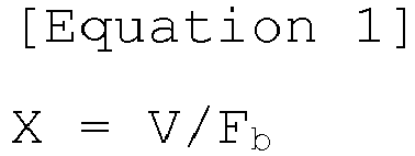

- The positive electrode active material for a secondary battery of claim 1, wherein the thickness (d) of the coating layer satisfies X<d<Xb (where Xb is the thickness of the coating layer when bulk resistance of the coating layer calculated by Equation 3 is 10 Ω) :

- The positive electrode active material for a secondary battery of claim 1, wherein the lithium ion conductive compound has a band gap of 5.8 eV to 10 eV.
- The positive electrode active material for a secondary battery of claim 1, wherein the lithium ion conductive compound has a lithium ion conductivity at 25°C of 1 × 10⁻⁸ S/cm to 1 × 10⁻² S/cm and a density of 0.5 g/cm3 or more.
- The positive electrode active material for a secondary battery of claim 1, wherein the lithium ion conductive compound is selected from the group consisting of Li2PO2N, LiBH4, LiBH4-LiI, and Li2NH.
- The positive electrode active material for a secondary battery of claim 1, wherein the lithium composite metal oxide is an oxide including lithium; and at least one metal selected from the group consisting of nickel, manganese, cobalt, and aluminum.
- The positive electrode active material for a secondary battery of claim 1, wherein the lithium composite metal oxide is doped with at least one element selected from the group consisting of tungsten (W), molybdenum (Mo), zirconium (Zr), titanium (Ti), magnesium (Mg), tantalum (Ta), aluminum (Al), iron (Fe), vanadium (V), chromium (Cr), barium (Ba), calcium (Ca), and niobium (Nb).
- A method of preparing a positive electrode active material for a secondary battery, the method comprising forming a film-shaped coating layer on a core including a lithium composite metal oxide to a thickness (d) satisfying X<d≤100X (where X is a maximum distance at which electrons are capable of passing through the coating layer by a dielectric breakdown electric field when charging to an open circuit voltage of the lithium composite metal oxide versus lithium, wherein X is determined by Equation 1) using at least one lithium ion conductive compound having a band gap of 5.5 eV to 10 eV,
wherein the thickness (d) of the coating layer is less than 500 nm, and
the lithium ion conductive compound is selected from the group consisting of lithium sulfide, lithium nitride, and lithium hydride:

- A positive electrode for a secondary battery, the positive electrode comprising the positive electrode active material of any one of claims 1 to 7.
- A lithium secondary battery comprising the positive electrode of claim 9, a negative electrode, a separator disposed between the positive electrode and the negative electrode, and an electrolyte solution.
- The lithium secondary battery of claim 10, wherein the negative electrode comprises a lithium metal electrode.
Applications Claiming Priority (3)
| Application Number | Priority Date | Filing Date | Title |
|---|---|---|---|
| KR20160128582 | 2016-10-05 | ||
| KR1020170125953A KR102006726B1 (en) | 2016-10-05 | 2017-09-28 | Positive electrode active material for secondary battery and secondary battery comprising the same |
| PCT/KR2017/010966 WO2018066928A1 (en) | 2016-10-05 | 2017-09-29 | Cathode active material for secondary battery and secondary battery comprising same |
Publications (3)
| Publication Number | Publication Date |
|---|---|
| EP3514864A1 true EP3514864A1 (en) | 2019-07-24 |
| EP3514864A4 EP3514864A4 (en) | 2019-08-07 |
| EP3514864B1 EP3514864B1 (en) | 2024-05-15 |
Family
ID=61974446
Family Applications (1)
| Application Number | Title | Priority Date | Filing Date |
|---|---|---|---|
| EP17858722.6A Active EP3514864B1 (en) | 2016-10-05 | 2017-09-29 | Cathode active material for secondary battery and secondary battery comprising same |
Country Status (5)
| Country | Link |
|---|---|
| US (1) | US11380891B2 (en) |
| EP (1) | EP3514864B1 (en) |
| JP (1) | JP7027627B2 (en) |
| KR (1) | KR102006726B1 (en) |
| CN (1) | CN109804489B (en) |
Families Citing this family (2)
| Publication number | Priority date | Publication date | Assignee | Title |
|---|---|---|---|---|
| JP7415452B2 (en) * | 2019-11-05 | 2024-01-17 | セイコーエプソン株式会社 | Solid electrolyte coated positive electrode active material powder and method for producing solid electrolyte coated positive electrode active material powder |
| CN111900473B (en) * | 2020-07-16 | 2022-08-05 | 浙江大学 | Lithium ion battery electrolyte for improving performance of anode material and lithium ion battery |
Family Cites Families (25)
| Publication number | Priority date | Publication date | Assignee | Title |
|---|---|---|---|---|
| KR100467436B1 (en) * | 2002-10-18 | 2005-01-24 | 삼성에스디아이 주식회사 | Negative electrode for lithium-sulfur battery, method of preparing same, and lithium-sulfur battery comprising same |
| KR100478997B1 (en) | 2003-02-13 | 2005-03-31 | 제일모직주식회사 | Cathode active material for lithium secondary battery, producing method thereof and lithium secondary battery using the same |
| JP5135664B2 (en) | 2003-12-05 | 2013-02-06 | 日産自動車株式会社 | Cathode material for non-aqueous electrolyte lithium ion battery and battery using the same |
| JP2006100083A (en) | 2004-09-29 | 2006-04-13 | Matsushita Electric Ind Co Ltd | Negative electrode for battery and battery using this |
| US20060078790A1 (en) | 2004-10-05 | 2006-04-13 | Polyplus Battery Company | Solid electrolytes based on lithium hafnium phosphate for active metal anode protection |
| JP5470669B2 (en) * | 2005-05-13 | 2014-04-16 | 日産自動車株式会社 | Cathode material for non-aqueous electrolysis lithium ion battery, battery using the same, and method for producing cathode material for non-aqueous electrolysis lithium ion battery |
| KR101330616B1 (en) | 2007-04-04 | 2013-11-18 | 삼성에스디아이 주식회사 | Positive electrode for rechargable lithium battery and rechargable lithium battery comprising same |
| KR101050438B1 (en) | 2008-11-10 | 2011-07-19 | 주식회사 코캄 | A positive electrode active material for lithium secondary batteries having excellent safety, a method of manufacturing the same, and a lithium secondary battery comprising the same |
| WO2010079962A2 (en) | 2009-01-06 | 2010-07-15 | 주식회사 엘지화학 | Positive electrode active material for lithium secondary battery |
| CN102263258A (en) | 2010-08-10 | 2011-11-30 | 中信国安盟固利动力科技有限公司 | Positive electrode material of high voltage lithium battery |
| CN102569774B (en) | 2010-12-29 | 2015-05-13 | 比亚迪股份有限公司 | Cathode active material and preparation method thereof, cathode material and lithium ion battery |
| US9461303B2 (en) | 2011-05-13 | 2016-10-04 | Toyota Jidosha Kabushiki Kaisha | Electrode body, all solid state battery, and method for producing coated active material |
| CN103703594B (en) * | 2011-08-05 | 2016-03-16 | 旭硝子株式会社 | Positive electrode active material for lithium ion secondary battery |
| CN103022415A (en) * | 2011-09-26 | 2013-04-03 | 比亚迪股份有限公司 | Positive pole, preparation method thereof and lithium-ion battery |
| WO2013073038A1 (en) * | 2011-11-17 | 2013-05-23 | トヨタ自動車株式会社 | Electrolyte-coated positive electrode active material particles, all-solid-state battery, and production method for electrolyte-coated positive electrode active material particles |
| US9570748B2 (en) * | 2012-10-12 | 2017-02-14 | Ut-Battelle, Llc | Lipon coatings for high voltage and high temperature Li-ion battery cathodes |
| US9761907B2 (en) | 2013-05-07 | 2017-09-12 | Dowa Holdings Co., Ltd. | Positive-electrode active-material powder and manufacturing method therefor |
| BR112016004291B1 (en) | 2013-09-02 | 2021-08-24 | Tohoku Techno Arch Co., Ltd. | SOLID STATE BATTERY |
| KR101977995B1 (en) | 2013-12-24 | 2019-05-13 | 경북대학교 산학협력단 | Positive electrode active material coated with boron compounds for lithium secondary battery and preparation method thereof |
| KR102184372B1 (en) | 2014-02-10 | 2020-11-30 | 삼성에스디아이 주식회사 | Composite cathode active material, preparation method thereof, and cathode and lithium battery containing the same |
| JP6494194B2 (en) | 2014-07-04 | 2019-04-03 | マクセルホールディングス株式会社 | Coated positive electrode active material for lithium secondary battery, method for producing the same, and lithium secondary battery using the same |
| JP6431707B2 (en) * | 2014-07-08 | 2018-11-28 | 三菱瓦斯化学株式会社 | Electrode layer for all solid state battery and all solid state battery |
| KR101755121B1 (en) | 2014-10-31 | 2017-07-06 | 주식회사 엘지화학 | Lithium metal electrode for lithium secondary battery with safe protective layer and lithium secondary battery comprising the same |
| RU2690293C2 (en) * | 2014-12-22 | 2019-06-03 | Мицубиси Газ Кемикал Компани, Инк. | Ion conductor and method of its production |
| WO2017042659A1 (en) * | 2015-09-11 | 2017-03-16 | Umicore | Lithium metal oxide material, the use thereof in a positive electrode of a secondary battery and a method for preparing such a lithium metal oxide material |
-
2017
- 2017-09-28 KR KR1020170125953A patent/KR102006726B1/en active IP Right Grant
- 2017-09-29 EP EP17858722.6A patent/EP3514864B1/en active Active
- 2017-09-29 JP JP2019517278A patent/JP7027627B2/en active Active
- 2017-09-29 US US16/339,638 patent/US11380891B2/en active Active
- 2017-09-29 CN CN201780061473.4A patent/CN109804489B/en active Active
Also Published As
| Publication number | Publication date |
|---|---|
| US11380891B2 (en) | 2022-07-05 |
| EP3514864B1 (en) | 2024-05-15 |
| US20200044246A1 (en) | 2020-02-06 |
| KR20180037899A (en) | 2018-04-13 |
| JP7027627B2 (en) | 2022-03-02 |
| CN109804489A (en) | 2019-05-24 |
| EP3514864A4 (en) | 2019-08-07 |
| KR102006726B1 (en) | 2019-08-02 |
| JP2019530184A (en) | 2019-10-17 |
| CN109804489B (en) | 2022-04-05 |
Similar Documents
| Publication | Publication Date | Title |
|---|---|---|
| EP3712990B1 (en) | Cathode active material for secondary battery, preparation method therefor, and lithium secondary battery comprising same | |
| US11121357B2 (en) | Positive electrode active material for secondary battery and method of preparing the same | |
| US11031595B2 (en) | Positive electrode active material for lithium secondary battery, method of preparing the same, and positive electrode for lithium secondary battery and lithium secondary battery which include the positive electrode active material | |
| US11876210B2 (en) | Positive electrode active material for lithium secondary battery, method of preparing the same, and positive electrode for lithium secondary battery and lithium secondary battery which include the positive electrode active material | |
| US20230327107A1 (en) | Positive Electrode Active Material for Secondary Battery, Method of Preparing the Same, and Lithium Secondary Battery Including the Positive Electrode Active Material | |
| US11476456B2 (en) | Lithium cobalt-based positive electrode active material, preparation method thereof, positive electrode and secondary battery including the same | |
| EP4064391A1 (en) | Cathode active material for lithium secondary battery and method for producing same | |
| US11764347B2 (en) | Method of preparing positive electrode active material for secondary battery and secondary battery using the same | |
| EP3584222B1 (en) | Method for preparing positive electrode active material for lithium secondary battery | |
| EP3876315A1 (en) | Lithium secondary battery | |
| EP4047693A1 (en) | Cathode active material for lithium secondary battery and method for preparing cathode active material | |
| EP3514864B1 (en) | Cathode active material for secondary battery and secondary battery comprising same | |
| US11316151B2 (en) | Positive electrode active material for lithium secondary battery, method of preparing the same, and positive electrode for lithium secondary battery and lithium secondary battery which include the positive electrode active material | |
| EP4203098A1 (en) | Method for manufacturing lithium secondary battery, and lithium secondary battery manufactured thereby | |
| EP3686160A2 (en) | Lithium cobalt-based positive electrode active material, method for preparing same, positive electrode comprising same, and secondary battery | |
| EP4235862A1 (en) | Cathode active material, and cathode and lithium secondary battery comprising same | |
| EP4246624A1 (en) | Method for preparing positive electrode active material, and positive electrode active material | |
| US20230352654A1 (en) | Method of Preparing Positive Electrode Active Material | |
| EP3780189A1 (en) | Cathode for secondary battery, method for manufacturing same, and lithium secondary battery including same |
Legal Events
| Date | Code | Title | Description |
|---|---|---|---|
| STAA | Information on the status of an ep patent application or granted ep patent |
Free format text: STATUS: THE INTERNATIONAL PUBLICATION HAS BEEN MADE |
|
| PUAI | Public reference made under article 153(3) epc to a published international application that has entered the european phase |
Free format text: ORIGINAL CODE: 0009012 |
|
| STAA | Information on the status of an ep patent application or granted ep patent |
Free format text: STATUS: REQUEST FOR EXAMINATION WAS MADE |
|
| 17P | Request for examination filed |
Effective date: 20190416 |
|
| AK | Designated contracting states |
Kind code of ref document: A1 Designated state(s): AL AT BE BG CH CY CZ DE DK EE ES FI FR GB GR HR HU IE IS IT LI LT LU LV MC MK MT NL NO PL PT RO RS SE SI SK SM TR |
|
| AX | Request for extension of the european patent |
Extension state: BA ME |
|
| A4 | Supplementary search report drawn up and despatched |
Effective date: 20190709 |
|
| RIC1 | Information provided on ipc code assigned before grant |
Ipc: H01M 4/525 20100101ALI20190703BHEP Ipc: H01M 10/052 20100101ALN20190703BHEP Ipc: H01M 4/1391 20100101ALI20190703BHEP Ipc: H01M 4/36 20060101AFI20190703BHEP Ipc: H01M 4/131 20100101ALI20190703BHEP Ipc: H01M 4/485 20100101ALI20190703BHEP Ipc: H01M 4/505 20100101ALI20190703BHEP |
|
| DAV | Request for validation of the european patent (deleted) | ||
| DAX | Request for extension of the european patent (deleted) | ||
| STAA | Information on the status of an ep patent application or granted ep patent |
Free format text: STATUS: EXAMINATION IS IN PROGRESS |
|
| 17Q | First examination report despatched |
Effective date: 20200514 |
|
| STAA | Information on the status of an ep patent application or granted ep patent |
Free format text: STATUS: EXAMINATION IS IN PROGRESS |
|
| STAA | Information on the status of an ep patent application or granted ep patent |
Free format text: STATUS: EXAMINATION IS IN PROGRESS |
|
| RAP1 | Party data changed (applicant data changed or rights of an application transferred) |
Owner name: LG ENERGY SOLUTION LTD. |
|
| RAP3 | Party data changed (applicant data changed or rights of an application transferred) |
Owner name: LG ENERGY SOLUTION, LTD. |
|
| GRAP | Despatch of communication of intention to grant a patent |
Free format text: ORIGINAL CODE: EPIDOSNIGR1 |
|
| GRAJ | Information related to disapproval of communication of intention to grant by the applicant or resumption of examination proceedings by the epo deleted |
Free format text: ORIGINAL CODE: EPIDOSDIGR1 |
|
| RIC1 | Information provided on ipc code assigned before grant |
Ipc: H01M 10/052 20100101ALN20231211BHEP Ipc: H01M 4/1391 20100101ALI20231211BHEP Ipc: H01M 4/131 20100101ALI20231211BHEP Ipc: H01M 4/505 20100101ALI20231211BHEP Ipc: H01M 4/525 20100101ALI20231211BHEP Ipc: H01M 4/485 20100101ALI20231211BHEP Ipc: H01M 4/36 20060101AFI20231211BHEP |
|
| GRAP | Despatch of communication of intention to grant a patent |
Free format text: ORIGINAL CODE: EPIDOSNIGR1 |
|
| STAA | Information on the status of an ep patent application or granted ep patent |
Free format text: STATUS: GRANT OF PATENT IS INTENDED |
|
| INTG | Intention to grant announced |
Effective date: 20240123 |
|
| RIC1 | Information provided on ipc code assigned before grant |
Ipc: H01M 10/052 20100101ALN20240112BHEP Ipc: H01M 4/1391 20100101ALI20240112BHEP Ipc: H01M 4/131 20100101ALI20240112BHEP Ipc: H01M 4/505 20100101ALI20240112BHEP Ipc: H01M 4/525 20100101ALI20240112BHEP Ipc: H01M 4/485 20100101ALI20240112BHEP Ipc: H01M 4/36 20060101AFI20240112BHEP |
|
| GRAS | Grant fee paid |
Free format text: ORIGINAL CODE: EPIDOSNIGR3 |
|
| GRAA | (expected) grant |
Free format text: ORIGINAL CODE: 0009210 |
|
| STAA | Information on the status of an ep patent application or granted ep patent |
Free format text: STATUS: THE PATENT HAS BEEN GRANTED |
|
| AK | Designated contracting states |
Kind code of ref document: B1 Designated state(s): AL AT BE BG CH CY CZ DE DK EE ES FI FR GB GR HR HU IE IS IT LI LT LU LV MC MK MT NL NO PL PT RO RS SE SI SK SM TR |
|
| REG | Reference to a national code |
Ref country code: CH Ref legal event code: EP Ref country code: GB Ref legal event code: FG4D |