EP3514375B1 - Shafting cooling system and method for controlling same, and wind power generator set - Google Patents
Shafting cooling system and method for controlling same, and wind power generator set Download PDFInfo
- Publication number
- EP3514375B1 EP3514375B1 EP18811124.9A EP18811124A EP3514375B1 EP 3514375 B1 EP3514375 B1 EP 3514375B1 EP 18811124 A EP18811124 A EP 18811124A EP 3514375 B1 EP3514375 B1 EP 3514375B1
- Authority
- EP
- European Patent Office
- Prior art keywords
- shaft
- air
- temperature
- cooling system
- stationary
- Prior art date
- Legal status (The legal status is an assumption and is not a legal conclusion. Google has not performed a legal analysis and makes no representation as to the accuracy of the status listed.)
- Active
Links
Images



Classifications
-
- F—MECHANICAL ENGINEERING; LIGHTING; HEATING; WEAPONS; BLASTING
- F03—MACHINES OR ENGINES FOR LIQUIDS; WIND, SPRING, OR WEIGHT MOTORS; PRODUCING MECHANICAL POWER OR A REACTIVE PROPULSIVE THRUST, NOT OTHERWISE PROVIDED FOR
- F03D—WIND MOTORS
- F03D80/00—Details, components or accessories not provided for in groups F03D1/00 - F03D17/00
- F03D80/60—Cooling or heating of wind motors
-
- F—MECHANICAL ENGINEERING; LIGHTING; HEATING; WEAPONS; BLASTING
- F03—MACHINES OR ENGINES FOR LIQUIDS; WIND, SPRING, OR WEIGHT MOTORS; PRODUCING MECHANICAL POWER OR A REACTIVE PROPULSIVE THRUST, NOT OTHERWISE PROVIDED FOR
- F03D—WIND MOTORS
- F03D80/00—Details, components or accessories not provided for in groups F03D1/00 - F03D17/00
- F03D80/70—Bearing or lubricating arrangements
-
- F—MECHANICAL ENGINEERING; LIGHTING; HEATING; WEAPONS; BLASTING
- F16—ENGINEERING ELEMENTS AND UNITS; GENERAL MEASURES FOR PRODUCING AND MAINTAINING EFFECTIVE FUNCTIONING OF MACHINES OR INSTALLATIONS; THERMAL INSULATION IN GENERAL
- F16C—SHAFTS; FLEXIBLE SHAFTS; ELEMENTS OR CRANKSHAFT MECHANISMS; ROTARY BODIES OTHER THAN GEARING ELEMENTS; BEARINGS
- F16C37/00—Cooling of bearings
- F16C37/007—Cooling of bearings of rolling bearings
-
- F—MECHANICAL ENGINEERING; LIGHTING; HEATING; WEAPONS; BLASTING
- F05—INDEXING SCHEMES RELATING TO ENGINES OR PUMPS IN VARIOUS SUBCLASSES OF CLASSES F01-F04
- F05B—INDEXING SCHEME RELATING TO WIND, SPRING, WEIGHT, INERTIA OR LIKE MOTORS, TO MACHINES OR ENGINES FOR LIQUIDS COVERED BY SUBCLASSES F03B, F03D AND F03G
- F05B2260/00—Function
- F05B2260/20—Heat transfer, e.g. cooling
- F05B2260/208—Heat transfer, e.g. cooling using heat pipes
-
- F—MECHANICAL ENGINEERING; LIGHTING; HEATING; WEAPONS; BLASTING
- F05—INDEXING SCHEMES RELATING TO ENGINES OR PUMPS IN VARIOUS SUBCLASSES OF CLASSES F01-F04
- F05B—INDEXING SCHEME RELATING TO WIND, SPRING, WEIGHT, INERTIA OR LIKE MOTORS, TO MACHINES OR ENGINES FOR LIQUIDS COVERED BY SUBCLASSES F03B, F03D AND F03G
- F05B2260/00—Function
- F05B2260/20—Heat transfer, e.g. cooling
- F05B2260/232—Heat transfer, e.g. cooling characterised by the cooling medium
-
- F—MECHANICAL ENGINEERING; LIGHTING; HEATING; WEAPONS; BLASTING
- F05—INDEXING SCHEMES RELATING TO ENGINES OR PUMPS IN VARIOUS SUBCLASSES OF CLASSES F01-F04
- F05B—INDEXING SCHEME RELATING TO WIND, SPRING, WEIGHT, INERTIA OR LIKE MOTORS, TO MACHINES OR ENGINES FOR LIQUIDS COVERED BY SUBCLASSES F03B, F03D AND F03G
- F05B2260/00—Function
- F05B2260/60—Fluid transfer
- F05B2260/64—Aeration, ventilation, dehumidification or moisture removal of closed spaces
-
- F—MECHANICAL ENGINEERING; LIGHTING; HEATING; WEAPONS; BLASTING
- F16—ENGINEERING ELEMENTS AND UNITS; GENERAL MEASURES FOR PRODUCING AND MAINTAINING EFFECTIVE FUNCTIONING OF MACHINES OR INSTALLATIONS; THERMAL INSULATION IN GENERAL
- F16C—SHAFTS; FLEXIBLE SHAFTS; ELEMENTS OR CRANKSHAFT MECHANISMS; ROTARY BODIES OTHER THAN GEARING ELEMENTS; BEARINGS
- F16C19/00—Bearings with rolling contact, for exclusively rotary movement
- F16C19/22—Bearings with rolling contact, for exclusively rotary movement with bearing rollers essentially of the same size in one or more circular rows, e.g. needle bearings
- F16C19/24—Bearings with rolling contact, for exclusively rotary movement with bearing rollers essentially of the same size in one or more circular rows, e.g. needle bearings for radial load mainly
- F16C19/28—Bearings with rolling contact, for exclusively rotary movement with bearing rollers essentially of the same size in one or more circular rows, e.g. needle bearings for radial load mainly with two or more rows of rollers
-
- F—MECHANICAL ENGINEERING; LIGHTING; HEATING; WEAPONS; BLASTING
- F16—ENGINEERING ELEMENTS AND UNITS; GENERAL MEASURES FOR PRODUCING AND MAINTAINING EFFECTIVE FUNCTIONING OF MACHINES OR INSTALLATIONS; THERMAL INSULATION IN GENERAL
- F16C—SHAFTS; FLEXIBLE SHAFTS; ELEMENTS OR CRANKSHAFT MECHANISMS; ROTARY BODIES OTHER THAN GEARING ELEMENTS; BEARINGS
- F16C2360/00—Engines or pumps
- F16C2360/31—Wind motors
-
- Y—GENERAL TAGGING OF NEW TECHNOLOGICAL DEVELOPMENTS; GENERAL TAGGING OF CROSS-SECTIONAL TECHNOLOGIES SPANNING OVER SEVERAL SECTIONS OF THE IPC; TECHNICAL SUBJECTS COVERED BY FORMER USPC CROSS-REFERENCE ART COLLECTIONS [XRACs] AND DIGESTS
- Y02—TECHNOLOGIES OR APPLICATIONS FOR MITIGATION OR ADAPTATION AGAINST CLIMATE CHANGE
- Y02E—REDUCTION OF GREENHOUSE GAS [GHG] EMISSIONS, RELATED TO ENERGY GENERATION, TRANSMISSION OR DISTRIBUTION
- Y02E10/00—Energy generation through renewable energy sources
- Y02E10/70—Wind energy
- Y02E10/72—Wind turbines with rotation axis in wind direction
Definitions
- the present application relates to the field of wind power generation, and particularly relates to a cooling system for a shafting of a wind turbine, a wind turbine including the cooling system and a control method of the cooling system.
- Wind turbines mostly employ permanent-magnet direct-drive wind power generators.
- the wind turbine with a permanent-magnet direct-drive wind power generator mainly includes: blades 1, a hub 2, a generator subsystem 3, a nacelle 4 and a tower 5.
- the generator subsystem 3 mainly includes: a permanent-magnet direct-drive wind power generator 6, a stationary shaft 7, a rotating shaft 9, and a main bearing.
- the main bearing includes an inner ring 10, rollers 8 and an outer ring 11, the inner ring 10 is connected to the rotating shaft 9, and the outer ring 11 is connected to the stationary shaft 7.
- the main bearing is one of the core components of the wind turbine, and the service life of the main bearing affects the service life of the entire wind turbine. Once the main bearing fails, the replacement of the main bearing is very difficult and expensive.
- the main bearing In order to ensure the normal operation of the main bearing, the main bearing needs to be lubricated.
- grease lubrication is generally used because compared to the oil lubrication, the grease lubrication device is simpler and the grease is less likely to leak, which is convenient for the maintenance of the main bearing.
- the wind turbine may be installed in coastal areas, Gobi and grassland areas, and the climatic conditions vary greatly between these areas. If the heat generated in the main bearing cannot be effectively dissipated, and additionally the wind turbine is located in a harsh environment (such as a high temperature environment), the main bearing may operate under a high temperature continuously, and the service life of the grease will decrease rapidly as the temperature increases, thereby causing failure of the lubricating function of the grease.
- the rollers 8, the inner ring 10 and the outer ring 11 are subjected to the external wind loads and bear the weight of the wind turbine itself, a large friction torque is produced when the inner ring 10 and the outer ring 11 rotate relative to each other, and thus large amounts of heat is generated inside the main bearing. If the generated heat cannot be dissipated in real time, the main bearing will have a high temperature, and the high temperature will cause the viscosity of the grease to decrease, further affecting the formation of the lubricating oil film between the inner ring 10, the rollers 8 and the outer ring 11 of the main bearing.
- WO 2013/152850 A1 discloses an adjusting device for the bearing of a wind turbine rotor.
- the adjusting device can be used in combination with the previously described adjusting mechanisms.
- the adjusting device can be designed for both heating and cooling, thereby allowing systematic adjustment of preload depending on the particular requirement profile.
- Three different temperature control zones are provided along the axial direction, namely, a tower-side zone, an intermediate zone and a rotor-side zone. Different temperatures can be set in the various temperature control zones, and the stator unit and rotor unit in general are systematically temperature-controlled via these temperature control zones.
- An object of the present application is to provide a cooling system for a shafting of a wind turbine so as to effectively dissipate the heat of the shafting.
- a cooling system for a shafting of a wind turbine is provided according to an aspect of the present application.
- the shafting includes a stationary shaft, a rotating shaft, and a bearing provided between the stationary shaft and the rotating shaft, the bearing includes an outer ring, rollers and an inner ring, the outer ring is connected to the stationary shaft, and the inner ring is connected to the rotating shaft.
- the cooling system includes: a cold air supply unit; and a rotating-shaft air blow box, the rotating-shaft air blow box is mounted on an inner surface of the stationary shaft and in a shape of a circular ring-shaped box, multiple first air blow openings are uniformly distributed in a surface, facing the rotating shaft, of the rotating-shaft air blow box in a circumferential direction, to blow cold air from the cold air supply unit to the rotating shaft, and each of the multiple first air blow openings is in a shape of a slit to form a jet, thereby enhancing heat exchange and improving the cooling effect of the rotating shaft.
- the cooling system further includes a stationary-shaft air blow box, the stationary-shaft air blow box is mounted on the inner surface of the stationary shaft and is in a shape of a circular ring-shaped box, multiple second air blow openings are uniformly distributed in a surface, facing the shafting, of the stationary-shaft air blow box in a circumferential direction, to blow the cold air from the cold air supply unit to the outer ring, and each of the multiple second air blow openings is in a shape of a slit to form a jet, thereby enhancing heat exchange and improving the cooling effect of the rotating shaft.
- the cooling system further includes an annular heat dissipation assembly fixedly mounted on an inner surface of the rotating shaft, in order to better dissipate the heat from the shafting.
- the annular heat dissipation assembly includes multiple heat dissipation units, and each of the multiple heat dissipation units includes a base plate and a heat pipe embedded in the base plate, in order to facilitate the installation of the annular heat dissipation assembly.
- the heat pipe includes a first extension portion extending inward along a radial direction of the rotating shaft from the base plate, a second extension portion extending along an axial direction of the rotating shaft from an end of the first extension portion, and a third extension portion extending inward along the radial direction of the rotating shaft from an end of the second extension portion, and each of the plurality of the heat dissipation units further includes heat dissipation fins interposed in the third extension portion, in order to more effectively dissipate heat.
- the heat pipe includes a single pipe formed by bending or multiple pipes arranged in parallel with each other.
- the annular heat dissipation assembly is mounted on the inner surface of the rotating shaft by a pressing strip, the pressing strip is formed by splicing multiple arc segments together, and is configured to support inner surfaces of the multiple base plates to fixedly mount the annular heat dissipation assembly on the inner surface of the rotating shaft, in order to securely mount the annular heat dissipation assembly in a simple manner.
- the cold air supply unit includes: a condenser and an air treatment tank.
- the condenser is mounted on a nacelle of the wind turbine.
- the air treatment tank includes: an evaporator forming a circulation loop with the condenser through a cooling medium pipe; and an air inlet for introducing external air.
- the air treatment tank further includes: a first air blow opening in communication with the rotating-shaft air blow box, and a second air blow opening in communication with the stationary-shaft air blow box; and fans are respectively provided in the vicinity of the first air blow opening and the second air blow opening, thus the flow rate and flow amount of the blown cold air can be adjusted by adjusting the speed of the fans.
- the cooling system further includes an annular fixing bracket for fixing the rotating-shaft air blow box, the stationary-shaft air blow box and the air treatment tank, thereby effectively utilizing an internal space of the shafting.
- a wind turbine is provided according to another aspect of the present application, where the wind turbine includes the above cooling system.
- a control method for the cooling system including: determining whether a temperature of the shafting is higher than a preset temperature threshold in a case that the wind turbine is in operation; operating the cooling system in a first operation mode if the temperature of the shafting is lower than the preset temperature threshold; and operating the cooling system in a second operation mode if the temperature of the shafting is higher than the preset temperature threshold; and wherein the cold air supply unit supplies natural wind in the first operation mode and supplies cold air in the second operation mode, thereby reducing energy consumption and improving energy efficiency.
- the method includes: calculating a temperature difference between the inner ring and the outer ring in the first operation mode; supplying a first preset air amount to the outer ring and a second preset air amount to the rotating shaft in a case that an absolute value of the temperature difference is smaller than a first preset temperature value; and adjusting an air supply amount of the cold air supply unit in a case that the absolute value of the temperature difference is greater than or equal to the first preset temperature value, to increase an air amount supplied to one having a higher temperature between the inner ring and the outer ring and reduce an air amount supplied to the other one having a lower temperature between the inner ring and the outer ring.
- the method includes: calculating the absolute value of the temperature difference between the inner ring and the outer ring in the second operation mode;
- the preset temperature threshold is embodied as 35 °C
- the first preset temperature value (a) is embodied as 5 °C
- the second preset temperature value (b) is embodied as 60 °C.
- the cooling system according to the present application is added after the design of the wind turbine is completed according to the spatial layout of the wind turbine, thereby achieving reliable installation and operation of the cooling system without affecting the operation of other components in the wind turbine.
- the cooling system according to the present application can effectively and specifically dissipate heat from the shafting through the combination of the cooling system and the annular heat dissipation assembly, thereby ensuring that the temperature of the shafting in the wind turbine is within a reasonable working range.
- the cooling system according to the present application has air blow boxes respectively corresponding to the inner ring and the outer ring, so that the inner and outer rings can be synchronously cooled to guarantee the temperature difference between the inner and outer rings, thereby ensuring the working clearance of the bearing.
- the air blow openings of the air blow box according to the present application can form a jet, thereby enhancing heat exchange to obtain a better cooling effect.
- a main bearing of a wind turbine will be described as a cooling object, but it should be noted that the present application is not limited to this, and the cooling system according to the exemplary embodiments may also be applied to other shafting of the wind turbine.
- the description about the directions is based on the shape of the main bearing, for example, descriptions such as “inside”, “outside”, “inner surface” and “inner surface” are based on a radial direction of the main bearing, specifically, the side that is close to the central axis of the main bearing and faces the central axis is “inside” or “inner surface”, and the opposite side is “outside” or “outer surface”.
- Figure 3 is a partially sectional view showing the breakdown structure of a wind turbine including a cooling system according to an embodiment of the present application
- Figure 4 is a partially schematic view showing the structure of a cooling system according to an embodiment of the present application
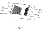
- Figure 5 is a schematic view showing the internal structure of an air treatment tank according to an embodiment of the present application.
- a cooling system includes: a cold air supply unit; and a rotating-shaft air blow box 19.
- the rotating-shaft air blow box 19 is mounted on an inner surface of a stationary shaft 7 and is in the shape of a circular ring-shaped box, multiple first air blow openings 19a are uniformly distributed in a surface, facing a rotating shaft 9, of the rotating-shaft air blow box 19 in a circumferential direction, to blow cold air from the cold air supply unit to the rotating shaft 9.
- Each of the multiple first air blow openings 19a is in the shape of a slit, to form a jet.
- the reason why the jet is formed is that: when the fluid flows from a relatively large space (the rotating-shaft air blow box 19) to a small space (the slit-shaped first air blow openings 19a), the air flow speed is increased, and the air flow pressure is increased, so that the air is ejected from the large space at a high speed and the heat transfer coefficient of forced convection is increased to more effectively cool the rotating shaft 9, and thus in turn cooling an inner ring 10.
- the cooling system further includes a stationary-shaft air blow box 16.
- the stationary-shaft air blow box 16 may also be mounted on the inner surface of the stationary shaft 7 and is in the shape of a circular ring-shaped box. Similar to the rotating-shaft air blow box 19, multiple second air blow openings 16a are uniformly distributed in a surface, facing the main bearing, of the stationary-shaft air blow box 16 in a circumferential direction, to blow cold air from the cold air supply unit to an outer ring 11. Each of the multiple second air blow openings 16a is in the shape of a slit to form a jet.
- the air blown to the outer ring 11 and the rotating shaft 9 as referred to herein does not mean that the air is blown onto the outer ring 11 and the rotating shaft 9 very accurately, but means that the air may be blown to places adjacent to the outer ring 11, or blown onto the components (for example, rollers 8) adjacent to the bearing ring 11, or blown to the vicinity of the rotating shaft 9.
- the stationary-shaft air blow box 16 and the rotating-shaft air blow box 19 may also be formed as an integral structure, that is, the stationary-shaft air blow box 16 and the rotating-shaft air blow box 19 may be integrally formed into a circular ring-shaped box, and the box is divided by a partition plate into two air passages respectively facing different areas, so that cold air can be respectively blown to the vicinity of the outer ring 11 and the vicinity of the rotating shaft 9 in the form of a jet.
- the rotating-shaft air blow box 19 may be mounted on an inner surface of the stationary-shaft air blow box 16, to be indirectly mounted on the inner surface of the stationary shaft 7 through the stationary-shaft air blow box 16, so that the inner space of the main bearing can be utilized more effectively.
- annular heat dissipation assembly 15 may be mounted on an inner surface of the rotating shaft 9.
- the cooling system may further include the annular heat dissipation assembly 15.
- the annular heat dissipation assembly 15 may include multiple heat dissipation units, and each of the multiple heat dissipation units includes a base plate 22 and a heat pipe 20 embedded in the base plate 20.
- the heat pipe 20 includes a first extension portion extending inward along a radial direction of the rotating shaft 9 from the base plate 22, a second extension portion extending along an axial direction of the rotating shaft 9 from an end of the first extension portion, and a third extension portion extending inward along the radial direction of the rotating shaft 9 from an end of the second extension portion.
- Each of the heat dissipation units further includes heat dissipation fins 21 interposed in the third extension portion, and the heat dissipation fins 21 are provided on an inner side of the base plate 22 along the radial direction of the rotating shaft 9, to achieve effective heat dissipation in a limited space through a reasonable layout.
- a cooling medium with a certain boiling point is within the heat pipe 20.
- the bottom of the heat pipe 20 (the portion closer to the rotating shaft 9 than the other portions of the heat pipe 20) absorbs heat, the cooling medium inside the heat pipe 20 evaporates into a gaseous cooling medium, the gaseous cooling medium starts to cool down under the heat dissipation of the heat dissipation fins 21, the gaseous cooling medium condenses into a liquid cooling medium, and the liquid cooling medium returns to the bottom of the heat pipe again by capillary action, thereby realizing a heat transfer cycle to cool the rotating shaft 9.
- the heat pipe 20 includes multiple pipes arranged in parallel with each other is illustrated in Figure 4 , but the structure of the heat pipe 20 is not limited to this, and the heat pipe 20 may be embodied as a single pipe curved in a zigzag shape or multiple pipes curved in a zigzag shape.
- the heat transferred to the rotating shaft 9 is sequentially transmitted to the base plates 22, the heat pipes 20, and the heat dissipation fins 21, and the cold air blown by the air blow boxes dissipates heat from the heat dissipation fins 21, to further reduce the temperature of the main bearing.
- the structure of the annular heat dissipation assembly 15 according to the present application is not limited to this, and for example, the annular heat dissipation assembly 15 may only include the base plates 22 and the heat pipes 20 embedded in the base plates 22.
- the rotating shaft 9 is a large component, it is not allowed to punch the inner surface of the rotating shaft 9 to mount the base plates 22 in view of the performances such as strength and fatigue, so that an adhesive with high thermal conductivity and high bonding strength may be employed to fix the multiple base plates 22.
- the mounting manner of the base plates 22 is not limited to this, and an auxiliary mounting device may be employed as necessary.
- the pressing strip 18 may be formed by splicing multiple arc segments together, and the outer surface of the pressing strip 18 has a size corresponding to the size of the inner surfaces of the multiple base plates 22 of the annular heat dissipation assembly 15, thus the annular heat dissipation assembly 15 can be fixedly mounted on the inner surface of the rotating shaft 9 by using the pressing strip 18 to support the inner surfaces of the multiple base plates 22. That is, the pressing strip with an entire circumference formed by splicing the multiple arc segments fixes the annular heat dissipation assembly 15 by generating a tension away from the center of the circle.
- the manner of mounting the annular heat dissipation assembly 15 is not limited to the above manners, and any structure is feasible as long as it can fixedly mount the annular heat dissipation assembly 15 on the inner surface of the rotating shaft 9.
- the cold air supply unit may include a condenser 12 and an air treatment tank 14.
- the condenser 12 may be mounted on a nacelle 4 of the wind turbine.
- the air treatment tank 14 includes an air inlet 14a for introducing external air, and an evaporator 23 provided in the air treatment tank 14.
- the evaporator 23 can form a circulation loop with the condenser 12 through a cooling medium pipe 13, to cool the introduced external air.
- the condenser 12 is preferably mounted at the top of the nacelle 4, to discharge heat generated inside the wind turbine to the outside and to avoid additional temperature rise to the interior.
- a cooling medium is provided in the refrigeration system constituted by the condenser 12 and the evaporator 23.
- the cooling medium evaporates into a gaseous cooling medium in the evaporator 23, taking away heat of the air in the air treatment tank 14; the gaseous cooling medium flows to the condenser 12, and condensates into a liquid cooling medium in the condenser 12, releasing heat; and then the liquid cooling medium flows into the evaporator 23 again in the air treatment tank 14, and the above process is repeated.
- the air in the air treatment tank 14 is cooled by the phase transition of the cooling medium in the evaporator 23, and the cooled air can flow into the stationary-shaft air blow boxer 16 and the rotating-shaft air blow boxer 19 in the manner as described above.
- the air treatment box 14 further includes a first air outlet and a second air outlet.
- the first air outlet can be in communication with the rotating-shaft air blow box 19 through the rotating-shaft air blow assembly 25, and the second air outlet can be in communication with the stationary-shaft air blow box 16 through the stationary-shaft air blow assembly 24.
- Fans may be respectively provided in the vicinity of the first air outlet and the vicinity of the second air outlet (for example, the rotating-shaft air blow assembly 25 and the stationary-shaft air blow assembly 24), so that the flow rate and flow amount of the blown cold air can be adjusted by adjusting the speed of the fans.
- a flow meter may be provided at a downstream side of the fans to detect the amount of blown cold air.
- temperature sensors may be respectively provided on the outer ring 11 and the inner ring 10, to sense the temperatures of the outer ring 11 and the inner ring 10, and the amount of air blown to the stationary-shaft air blow box 16 and the rotating-shaft air blow box 19 can be determined according to the sensed temperatures of the outer ring 11 and the inner ring 10. That is, more cold air is blown to a part having a higher temperature, and less cold air is blown to a part having a lower temperature, thereby specifically and effectively dissipating heat from the main bearing.
- the above solution will be described in detail below.
- the cooling system according to the embodiment further includes an annular fixing bracket 17 for fixing the rotating-shaft air blow box 19 and the stationary-shaft air blow box 16.
- the annular fixing bracket 17 may be in the shape of a ladder wound into an annular shape and can be fixed to the inner surface of the stationary shaft 7 by its own tension force.
- the outer side surfaces of the stationary-shaft air blow box 16 and the rotating-shaft air blow box 19 may each have a shape corresponding to the shape of the annular fixing bracket 17, and can be mounted to the annular fixing bracket 17 through a fastening member (not shown).
- the air treatment tank 14 can also be fixed to the stationary shaft 7 through the annular fixing bracket 17.
- the rotating-shaft air blow box 19, the stationary-shaft air blow box 16 and the air treatment box 14 can be fixed by a same annular fixing bracket 17 having a long length in the axial direction, or can be respectively fixed by their respective annular fixing brackets 17, which can be set according to the space in the stationary shaft 7 and the actual needs.
- the air treatment box 14 can be placed at a high position of the stationary shaft 7, so that the idle space of the shaft hole can be fully utilized without occupying a maintenance space of the shaft hole due to the additional equipment.
- the cooling system according to the embodiment performs a forced convection heat transfer by means of power consumption, which will increase the electric power consumption of the wind turbine itself without doubt. Therefore, a control method of the cooling system is provided in the present application, to reduce energy consumption and increase energy utilization.
- the wind turbine is in different external environments throughout the year, and only in summer the external environmental temperature is high and the temperature of air for dissipating heat from the main bearing is not required to be very low, therefore, the temperature of the main bearing can be controlled by combining the external natural wind and the cooling air generated by the cooling system.
- the cooling system may not work, the cooling capacity is 0, and the external natural wind is introduced to directly cool the main bearing;
- the cooling system is used to cool the air introduced into the air treatment tank 14, and at this time, the cooling capacity of the cooling system is M2; and when the external environmental temperature T is higher than or equal to the first temperature threshold T1 and lower than or equal to the second temperature threshold T2 (T1 ⁇ T ⁇ T2), the cooling system is used to control a certain proportion of the cooling capacity and external natural wind is partially introduced, at this time, the cooling capacity of the cooling system is M1, where M1 ⁇ M2.
- the first temperature threshold may be 30 °C and the second temperature threshold may be 35 °C.
- the temperature of the main bearing is usually related to the external environmental temperature. Normally, the temperature of the main bearing is not lower than the external environmental temperature, so that the main bearing can be cooled by the cooling system only according to the temperature of the main bearing.
- a preset temperature threshold (the preset temperature threshold may be 35 °C) when the wind turbine is in operation can be determined by a temperature sensor provided on the main bearing. If a detected temperature is lower than the preset temperature threshold, the cooling system operates in a first operation mode; and if the detected temperature is higher than the preset temperature threshold, the cooling system operates in a second operation mode. In the first operation mode, the cold air supply unit only supplies natural wind, and in the second operation mode, the cold air supply unit only supplies cold air. In addition, a bearing clearance is critical to the operational reliability of the main bearing, and temperature is an important factor affecting the operation of the main bearing.
- both the inner ring 10 and the outer ring 11 should be taken into consideration, to allow the inner ring 10 and the outer ring 11 to be cooled simultaneously, so that the temperature difference can be guaranteed to ensure the bearing clearance.
- the air amounts blown to the stationary-shaft air blow box 16 and the rotating-shaft air blow box 19 should be controlled regardless of the first operation mode or the second operation mode.
- a first preset air amount may be supplied to the stationary-shaft air blow box 16 and a second preset air amount may be supplied to the rotating-shaft air blow box 19, and the second preset air amount supplied to the rotating-shaft air blow box 19 may be greater than the first preset air amount supplied to the stationary-shaft blow box 16.
- Temperature sensors may be respectively arranged on the inner ring 10 and the outer ring 11 to sense the temperatures of the inner ring 10 and the outer ring 11.
- Figure 6 is a flow chart showing processes of controlling air supply amounts of the stationary-shaft air blow box 16 and the rotating-shaft air blow box 19 according to an embodiment of the present application. The control method will be described in detail below with reference to Figure 6 .
- the control method of Figure 6 is performed for the second operation mode, because in the first operation mode, the temperatures of the main bearing and the external environment are relatively low, thus it is only necessary to determine whether the temperature difference between the main bearing and the external environment is large. For example, it is determined whether the absolute value
- the temperature t1 of the inner ring 10 and the temperature t2 of the outer ring 11 can be respectively measured by temperature sensors.
- the first preset temperature value a for example, the first preset temperature value may be 5 °C.
- is smaller than the first preset temperature value a
- the air supply amounts for the stationary shaft and the rotating shaft are increased at the same time; if neither one of the temperature t1 of the inner ring 10 and the temperature t2 of the outer ring 11 is higher than or equal to the second preset temperature value (b), the first preset air amount and the second preset air amount may be maintained unchanged.
- the temperature t1 of the inner ring 10 is higher than the temperature t2 of the outer ring 11, it is determined whether the temperature t2 of the outer ring 11 having a lower temperature compared to the inner ring 10 is higher than or equal to the second preset temperature value b. If the temperature t2 is higher than or equal to the second preset temperature value b, it indicates that the temperature t1 of the inner ring 10 and the temperature t2 of the outer ring 11 both exceed the second preset temperature value b, so the air supply amounts for the stationary shaft and the rotating shaft are increased at the same time.
- the air supply amount for the inner ring 10 may be increased while the air supply amount for the outer ring 11 may be reduced (that is, the air supply amount for the rotating shaft is increased while the air supply amount for the stationary shaft is reduced).
- the temperature t1 of the inner ring 10 is not higher than the temperature t2 of the outer ring 11, it is determined whether the temperature t1 of the inner ring 10 having a lower temperature compared to the outer ring 11 is higher than or equal to the second preset temperature value b. Similar to the above process of determination, if the temperature t1 of the inner ring 10 is higher than or equal to the second preset temperature value b, the air supply amounts for the stationary shaft and the rotating shaft are increased at the same time; and if the temperature t1 of the inner ring 10 is lower than the second preset temperature value b, the air supply amount for the stationary shaft may be increased and the air supply amount for the rotating shaft may be reduced.
- the cooling system according to the present application is added after the design of the wind turbine is completed according to the spatial layout of the wind turbine, which can achieve reliable installation and operation without affecting the operation of other components within the wind turbine.
- the cooling system according to the present application can effectively and specifically dissipate heat from the main bearing through the combination of the cooling system and the annular heat dissipation assembly, so that the temperature the main bearing of the wind turbine is within a reasonable working range.
- the cooling system according to the present application has air blow boxes respectively corresponding to the inner ring and the outer ring, so that the inner and outer rings can be synchronously cooled, thereby guaranteeing the temperature difference between the inner and outer rings and ensuring the working clearance of the bearing.
- the air blow openings of the air blow box according to the present application can form a jet, thereby enhancing heat exchange to obtain a better cooling effect.
Landscapes
- Engineering & Computer Science (AREA)
- General Engineering & Computer Science (AREA)
- Mechanical Engineering (AREA)
- Life Sciences & Earth Sciences (AREA)
- Sustainable Development (AREA)
- Sustainable Energy (AREA)
- Chemical & Material Sciences (AREA)
- Combustion & Propulsion (AREA)
- Physics & Mathematics (AREA)
- Thermal Sciences (AREA)
- Mounting Of Bearings Or Others (AREA)
Description
- The present application relates to the field of wind power generation, and particularly relates to a cooling system for a shafting of a wind turbine, a wind turbine including the cooling system and a control method of the cooling system.
- Wind turbines mostly employ permanent-magnet direct-drive wind power generators. As shown in
Figure 1 (a schematic view showing the structure of a wind turbine), the wind turbine with a permanent-magnet direct-drive wind power generator mainly includes: blades 1, ahub 2, a generator subsystem 3, a nacelle 4 and atower 5. As shown inFigure 2 (a cross-sectional view of a portion A ofFigure 1 ), the generator subsystem 3 mainly includes: a permanent-magnet direct-drivewind power generator 6, astationary shaft 7, a rotating shaft 9, and a main bearing. The main bearing includes aninner ring 10,rollers 8 and anouter ring 11, theinner ring 10 is connected to the rotating shaft 9, and theouter ring 11 is connected to thestationary shaft 7. Since the blades 1 and thehub 2 are connected to the rotating shaft 9, the relative movement between the rotating shaft 9 and thestationary shaft 7 can be achieved by therollers 8 of the main bearing under the action of external wind loads. Therefore, the main bearing is one of the core components of the wind turbine, and the service life of the main bearing affects the service life of the entire wind turbine. Once the main bearing fails, the replacement of the main bearing is very difficult and expensive. - In order to ensure the normal operation of the main bearing, the main bearing needs to be lubricated. At present, there are two main lubrication methods for the main bearing: grease lubrication and oil lubrication. For rolling bearings, grease lubrication is generally used because compared to the oil lubrication, the grease lubrication device is simpler and the grease is less likely to leak, which is convenient for the maintenance of the main bearing.
- However, the wind turbine may be installed in coastal areas, Gobi and grassland areas, and the climatic conditions vary greatly between these areas. If the heat generated in the main bearing cannot be effectively dissipated, and additionally the wind turbine is located in a harsh environment (such as a high temperature environment), the main bearing may operate under a high temperature continuously, and the service life of the grease will decrease rapidly as the temperature increases, thereby causing failure of the lubricating function of the grease.
- Since the
rollers 8, theinner ring 10 and theouter ring 11 are subjected to the external wind loads and bear the weight of the wind turbine itself, a large friction torque is produced when theinner ring 10 and theouter ring 11 rotate relative to each other, and thus large amounts of heat is generated inside the main bearing. If the generated heat cannot be dissipated in real time, the main bearing will have a high temperature, and the high temperature will cause the viscosity of the grease to decrease, further affecting the formation of the lubricating oil film between theinner ring 10, therollers 8 and theouter ring 11 of the main bearing. As a result, dry friction may occur, causing the temperature of the components inside the transmission system to rise sharply, and the working clearance of the main bearing may exceed a reasonable working range due to the thermal expansion, and even a "shaft seizure" phenomenon may occur. It can be seen that long-term high-temperature operation will lead to severe vicious cycle, and seriously affect the service life of the main bearing, resulting in failure of the main bearing, which is unable to meet the requirement of allowing the wind turbine to have an operation life of 20 to 25 years. - In fact, not only the main bearing but also the bearings in other shafting have the above problems. Most failure modes of the bearings are ultimately caused by "heat". Moreover, as the power of the wind turbine increases gradually, the heat dissipation problem not only affects the service life of the grease, but also poses a threat (for example, internal components may melt due to high temperatures) to other components of the wind turbine, which attracts more and more attentions.
-
WO 2013/152850 A1 discloses an adjusting device for the bearing of a wind turbine rotor. The adjusting device can be used in combination with the previously described adjusting mechanisms. The adjusting device can be designed for both heating and cooling, thereby allowing systematic adjustment of preload depending on the particular requirement profile. Three different temperature control zones are provided along the axial direction, namely, a tower-side zone, an intermediate zone and a rotor-side zone. Different temperatures can be set in the various temperature control zones, and the stator unit and rotor unit in general are systematically temperature-controlled via these temperature control zones. - An object of the present application is to provide a cooling system for a shafting of a wind turbine so as to effectively dissipate the heat of the shafting.
- The object of the invention is achieved by the features of the independent claims. Further preferred embodiments of the present invention are defined in the dependent claim.
- A cooling system for a shafting of a wind turbine is provided according to an aspect of the present application. The shafting includes a stationary shaft, a rotating shaft, and a bearing provided between the stationary shaft and the rotating shaft, the bearing includes an outer ring, rollers and an inner ring, the outer ring is connected to the stationary shaft, and the inner ring is connected to the rotating shaft. The cooling system includes: a cold air supply unit; and a rotating-shaft air blow box, the rotating-shaft air blow box is mounted on an inner surface of the stationary shaft and in a shape of a circular ring-shaped box, multiple first air blow openings are uniformly distributed in a surface, facing the rotating shaft, of the rotating-shaft air blow box in a circumferential direction, to blow cold air from the cold air supply unit to the rotating shaft, and each of the multiple first air blow openings is in a shape of a slit to form a jet, thereby enhancing heat exchange and improving the cooling effect of the rotating shaft.
- The cooling system further includes a stationary-shaft air blow box, the stationary-shaft air blow box is mounted on the inner surface of the stationary shaft and is in a shape of a circular ring-shaped box, multiple second air blow openings are uniformly distributed in a surface, facing the shafting, of the stationary-shaft air blow box in a circumferential direction, to blow the cold air from the cold air supply unit to the outer ring, and each of the multiple second air blow openings is in a shape of a slit to form a jet, thereby enhancing heat exchange and improving the cooling effect of the rotating shaft.
- The cooling system further includes an annular heat dissipation assembly fixedly mounted on an inner surface of the rotating shaft, in order to better dissipate the heat from the shafting.
- The annular heat dissipation assembly includes multiple heat dissipation units, and each of the multiple heat dissipation units includes a base plate and a heat pipe embedded in the base plate, in order to facilitate the installation of the annular heat dissipation assembly.
- The heat pipe includes a first extension portion extending inward along a radial direction of the rotating shaft from the base plate, a second extension portion extending along an axial direction of the rotating shaft from an end of the first extension portion, and a third extension portion extending inward along the radial direction of the rotating shaft from an end of the second extension portion, and each of the plurality of the heat dissipation units further includes heat dissipation fins interposed in the third extension portion, in order to more effectively dissipate heat.
- The heat pipe includes a single pipe formed by bending or multiple pipes arranged in parallel with each other.
- The annular heat dissipation assembly is mounted on the inner surface of the rotating shaft by a pressing strip, the pressing strip is formed by splicing multiple arc segments together, and is configured to support inner surfaces of the multiple base plates to fixedly mount the annular heat dissipation assembly on the inner surface of the rotating shaft, in order to securely mount the annular heat dissipation assembly in a simple manner.
- The cold air supply unit includes: a condenser and an air treatment tank. The condenser is mounted on a nacelle of the wind turbine. The air treatment tank includes: an evaporator forming a circulation loop with the condenser through a cooling medium pipe; and an air inlet for introducing external air.
- The air treatment tank further includes: a first air blow opening in communication with the rotating-shaft air blow box, and a second air blow opening in communication with the stationary-shaft air blow box; and fans are respectively provided in the vicinity of the first air blow opening and the second air blow opening, thus the flow rate and flow amount of the blown cold air can be adjusted by adjusting the speed of the fans.
- The cooling system further includes an annular fixing bracket for fixing the rotating-shaft air blow box, the stationary-shaft air blow box and the air treatment tank, thereby effectively utilizing an internal space of the shafting.
- A wind turbine is provided according to another aspect of the present application, where the wind turbine includes the above cooling system.
- A control method for the cooling system is provided according to yet another aspect of the present application, including: determining whether a temperature of the shafting is higher than a preset temperature threshold in a case that the wind turbine is in operation; operating the cooling system in a first operation mode if the temperature of the shafting is lower than the preset temperature threshold; and operating the cooling system in a second operation mode if the temperature of the shafting is higher than the preset temperature threshold; and wherein the cold air supply unit supplies natural wind in the first operation mode and supplies cold air in the second operation mode, thereby reducing energy consumption and improving energy efficiency.
- The method includes: calculating a temperature difference between the inner ring and the outer ring in the first operation mode; supplying a first preset air amount to the outer ring and a second preset air amount to the rotating shaft in a case that an absolute value of the temperature difference is smaller than a first preset temperature value; and adjusting an air supply amount of the cold air supply unit in a case that the absolute value of the temperature difference is greater than or equal to the first preset temperature value, to increase an air amount supplied to one having a higher temperature between the inner ring and the outer ring and reduce an air amount supplied to the other one having a lower temperature between the inner ring and the outer ring.
- The method includes: calculating the absolute value of the temperature difference between the inner ring and the outer ring in the second operation mode;
- determining whether at least one of the inner ring and the outer ring has a temperature higher than or equal to a second preset temperature value in a case that the absolute value is smaller than the first preset temperature value; increasing air supply amounts for the stationary shaft and the rotating shaft at the same time if at least one of the inner ring and the outer ring has a temperature higher than or equal to the second preset temperature value; and maintaining the first preset air amount and the second preset air amount unchanged if neither one of the inner ring and the outer ring has a temperature higher than or equal to the second preset temperature value;
- determining whether a temperature of the inner ring is higher than a temperature of the outer ring in a case that the absolute value is greater than or equal to the first preset temperature value;
- determining whether the temperature of the outer ring is higher than or equal to the second preset temperature value if the temperature of the inner ring is higher than the temperature of the outer ring; increasing the air supply amounts for the stationary shaft and the rotating shaft at the same time if the temperature of the outer ring is higher than or equal to the second preset temperature value; and increasing the air supply amount for the rotating shaft and reducing the air supply amount for the stationary shaft if the temperature of the outer ring is lower than the second preset temperature value; and
- determining whether the temperature of the inner ring is higher than or equal to the second preset temperature value if the temperature of the inner ring is lower than or equal to the temperature of the outer ring; increasing the air supply amounts for the stationary shaft and the rotating shaft at the same time if the temperature of the inner ring is higher than or equal to the second preset temperature value; and increasing the air supply amount for the stationary shaft and reducing the air supply amount for the rotating shaft if the temperature of the inner ring is lower than the second preset temperature value.
- The preset temperature threshold is embodied as 35 °C, the first preset temperature value (a) is embodied as 5 °C, and the second preset temperature value (b) is embodied as 60 °C.
- The cooling system according to the present application is added after the design of the wind turbine is completed according to the spatial layout of the wind turbine, thereby achieving reliable installation and operation of the cooling system without affecting the operation of other components in the wind turbine.
- The cooling system according to the present application can effectively and specifically dissipate heat from the shafting through the combination of the cooling system and the annular heat dissipation assembly, thereby ensuring that the temperature of the shafting in the wind turbine is within a reasonable working range.
- The cooling system according to the present application has air blow boxes respectively corresponding to the inner ring and the outer ring, so that the inner and outer rings can be synchronously cooled to guarantee the temperature difference between the inner and outer rings, thereby ensuring the working clearance of the bearing.
- The air blow openings of the air blow box according to the present application can form a jet, thereby enhancing heat exchange to obtain a better cooling effect.
- According to the control method for the cooling system in the present application, specific temperature difference control logic is proposed for heat generation inside the main bearing caused by different external environmental temperatures and the operation characteristics of the wind turbine itself, thereby guaranteeing the clearance of the main bearing and ensuring the operation safety.
-
-
Figure 1 is a schematic view showing the structure of a wind turbine; -
Figure 2 is a cross-sectional view of a portion A ofFigure 1 ; -
Figure 3 is a partially sectional view showing the breakdown structure of a wind turbine including a cooling system according to an embodiment of the present application; -
Figure 4 is a partially schematic view showing the structure of a cooling system according to an embodiment of the present application; -
Figure 5 is a schematic view showing the internal structure of an air treatment tank according to an embodiment of the present application; and -
Figure 6 is a flow chart showing processes of controlling air supply amounts of a stationary-shaft air blow box and a rotating-shaft air blow box according to an embodiment of the present application. - The embodiments of the present application will be specifically described below in conjunction with the accompanying drawings.
- Hereinafter, a main bearing of a wind turbine will be described as a cooling object, but it should be noted that the present application is not limited to this, and the cooling system according to the exemplary embodiments may also be applied to other shafting of the wind turbine. In addition, the description about the directions is based on the shape of the main bearing, for example, descriptions such as "inside", "outside", "inner surface" and "inner surface" are based on a radial direction of the main bearing, specifically, the side that is close to the central axis of the main bearing and faces the central axis is "inside" or "inner surface", and the opposite side is "outside" or "outer surface".
-
Figure 3 is a partially sectional view showing the breakdown structure of a wind turbine including a cooling system according to an embodiment of the present application;Figure 4 is a partially schematic view showing the structure of a cooling system according to an embodiment of the present application;Figure 5 is a schematic view showing the internal structure of an air treatment tank according to an embodiment of the present application. - As shown in
Figures 3 to 5 , a cooling system according to an embodiment of the present application includes: a cold air supply unit; and a rotating-shaftair blow box 19. The rotating-shaftair blow box 19 is mounted on an inner surface of astationary shaft 7 and is in the shape of a circular ring-shaped box, multiple firstair blow openings 19a are uniformly distributed in a surface, facing a rotating shaft 9, of the rotating-shaftair blow box 19 in a circumferential direction, to blow cold air from the cold air supply unit to the rotating shaft 9. Each of the multiple firstair blow openings 19a is in the shape of a slit, to form a jet. The reason why the jet is formed is that: when the fluid flows from a relatively large space (the rotating-shaft air blow box 19) to a small space (the slit-shaped firstair blow openings 19a), the air flow speed is increased, and the air flow pressure is increased, so that the air is ejected from the large space at a high speed and the heat transfer coefficient of forced convection is increased to more effectively cool the rotating shaft 9, and thus in turn cooling aninner ring 10. - Moreover, the cooling system further includes a stationary-shaft
air blow box 16. The stationary-shaftair blow box 16 may also be mounted on the inner surface of thestationary shaft 7 and is in the shape of a circular ring-shaped box. Similar to the rotating-shaftair blow box 19, multiple secondair blow openings 16a are uniformly distributed in a surface, facing the main bearing, of the stationary-shaftair blow box 16 in a circumferential direction, to blow cold air from the cold air supply unit to anouter ring 11. Each of the multiple secondair blow openings 16a is in the shape of a slit to form a jet. - It should be noted that the air blown to the
outer ring 11 and the rotating shaft 9 as referred to herein does not mean that the air is blown onto theouter ring 11 and the rotating shaft 9 very accurately, but means that the air may be blown to places adjacent to theouter ring 11, or blown onto the components (for example, rollers 8) adjacent to thebearing ring 11, or blown to the vicinity of the rotating shaft 9. - By making the cold air flow out of the stationary-shaft
air blow box 16 and the rotating-shaftair blow box 19 in a form of a jet, the heat exchange is enhanced and the cooling effect is improved. - However, the structure of the air blow box is not limited to this. The stationary-shaft
air blow box 16 and the rotating-shaftair blow box 19 may also be formed as an integral structure, that is, the stationary-shaftair blow box 16 and the rotating-shaftair blow box 19 may be integrally formed into a circular ring-shaped box, and the box is divided by a partition plate into two air passages respectively facing different areas, so that cold air can be respectively blown to the vicinity of theouter ring 11 and the vicinity of the rotating shaft 9 in the form of a jet. - In addition, although a situation that the stationary-shaft
air blow box 16 and the rotating-shaftair blow box 19 are both mounted on the inner surface of thestationary shaft 7 are described above, it is also practicable that the rotating-shaftair blow box 19 may be mounted on an inner surface of the stationary-shaftair blow box 16, to be indirectly mounted on the inner surface of thestationary shaft 7 through the stationary-shaftair blow box 16, so that the inner space of the main bearing can be utilized more effectively. - Since heat generated by the friction between the
rollers 8 and theinner ring 10 and the friction between therollers 8 and theouter ring 11 is transmitted to theinner ring 10 in a radial direction, and further is transmitted to the rotating shaft 9, in order to realize better heat dissipation, an annularheat dissipation assembly 15 may be mounted on an inner surface of the rotating shaft 9. - As shown in
Figure 4 , the cooling system may further include the annularheat dissipation assembly 15. In order to facilitate the installation of the annularheat dissipation assembly 15, the annularheat dissipation assembly 15 may include multiple heat dissipation units, and each of the multiple heat dissipation units includes a base plate 22 and aheat pipe 20 embedded in thebase plate 20. Theheat pipe 20 includes a first extension portion extending inward along a radial direction of the rotating shaft 9 from the base plate 22, a second extension portion extending along an axial direction of the rotating shaft 9 from an end of the first extension portion, and a third extension portion extending inward along the radial direction of the rotating shaft 9 from an end of the second extension portion. Each of the heat dissipation units further includesheat dissipation fins 21 interposed in the third extension portion, and theheat dissipation fins 21 are provided on an inner side of the base plate 22 along the radial direction of the rotating shaft 9, to achieve effective heat dissipation in a limited space through a reasonable layout. - A cooling medium with a certain boiling point is within the
heat pipe 20. Through the heat conduction of the base plate 22, the bottom of the heat pipe 20 (the portion closer to the rotating shaft 9 than the other portions of the heat pipe 20) absorbs heat, the cooling medium inside theheat pipe 20 evaporates into a gaseous cooling medium, the gaseous cooling medium starts to cool down under the heat dissipation of theheat dissipation fins 21, the gaseous cooling medium condenses into a liquid cooling medium, and the liquid cooling medium returns to the bottom of the heat pipe again by capillary action, thereby realizing a heat transfer cycle to cool the rotating shaft 9. - In addition, a situation that the
heat pipe 20 includes multiple pipes arranged in parallel with each other is illustrated inFigure 4 , but the structure of theheat pipe 20 is not limited to this, and theheat pipe 20 may be embodied as a single pipe curved in a zigzag shape or multiple pipes curved in a zigzag shape. - By providing the annular
heat dissipation assembly 15, the heat transferred to the rotating shaft 9 is sequentially transmitted to the base plates 22, theheat pipes 20, and theheat dissipation fins 21, and the cold air blown by the air blow boxes dissipates heat from theheat dissipation fins 21, to further reduce the temperature of the main bearing. - However, the structure of the annular
heat dissipation assembly 15 according to the present application is not limited to this, and for example, the annularheat dissipation assembly 15 may only include the base plates 22 and theheat pipes 20 embedded in the base plates 22. - In addition, since the rotating shaft 9 is a large component, it is not allowed to punch the inner surface of the rotating shaft 9 to mount the base plates 22 in view of the performances such as strength and fatigue, so that an adhesive with high thermal conductivity and high bonding strength may be employed to fix the multiple base plates 22. However, the mounting manner of the base plates 22 is not limited to this, and an auxiliary mounting device may be employed as necessary.
- A situation that a
pressing strip 18 is used as an auxiliary mounting device for the annularheat dissipation assembly 15 is illustrated in an embodiment of the present application. Thepressing strip 18 may be formed by splicing multiple arc segments together, and the outer surface of thepressing strip 18 has a size corresponding to the size of the inner surfaces of the multiple base plates 22 of the annularheat dissipation assembly 15, thus the annularheat dissipation assembly 15 can be fixedly mounted on the inner surface of the rotating shaft 9 by using thepressing strip 18 to support the inner surfaces of the multiple base plates 22. That is, the pressing strip with an entire circumference formed by splicing the multiple arc segments fixes the annularheat dissipation assembly 15 by generating a tension away from the center of the circle. - However, the manner of mounting the annular
heat dissipation assembly 15 is not limited to the above manners, and any structure is feasible as long as it can fixedly mount the annularheat dissipation assembly 15 on the inner surface of the rotating shaft 9. - As shown in
Figure 3 , the cold air supply unit according to the embodiment may include acondenser 12 and anair treatment tank 14. Thecondenser 12 may be mounted on a nacelle 4 of the wind turbine. Theair treatment tank 14 includes anair inlet 14a for introducing external air, and anevaporator 23 provided in theair treatment tank 14. Theevaporator 23 can form a circulation loop with thecondenser 12 through a coolingmedium pipe 13, to cool the introduced external air. - The
condenser 12 is preferably mounted at the top of the nacelle 4, to discharge heat generated inside the wind turbine to the outside and to avoid additional temperature rise to the interior. A cooling medium is provided in the refrigeration system constituted by thecondenser 12 and theevaporator 23. The cooling medium evaporates into a gaseous cooling medium in theevaporator 23, taking away heat of the air in theair treatment tank 14; the gaseous cooling medium flows to thecondenser 12, and condensates into a liquid cooling medium in thecondenser 12, releasing heat; and then the liquid cooling medium flows into theevaporator 23 again in theair treatment tank 14, and the above process is repeated. The air in theair treatment tank 14 is cooled by the phase transition of the cooling medium in theevaporator 23, and the cooled air can flow into the stationary-shaftair blow boxer 16 and the rotating-shaftair blow boxer 19 in the manner as described above. - In addition, the
air treatment box 14 further includes a first air outlet and a second air outlet. The first air outlet can be in communication with the rotating-shaftair blow box 19 through the rotating-shaftair blow assembly 25, and the second air outlet can be in communication with the stationary-shaftair blow box 16 through the stationary-shaftair blow assembly 24. Fans may be respectively provided in the vicinity of the first air outlet and the vicinity of the second air outlet (for example, the rotating-shaftair blow assembly 25 and the stationary-shaft air blow assembly 24), so that the flow rate and flow amount of the blown cold air can be adjusted by adjusting the speed of the fans. In addition, a flow meter may be provided at a downstream side of the fans to detect the amount of blown cold air. - Further, temperature sensors may be respectively provided on the
outer ring 11 and theinner ring 10, to sense the temperatures of theouter ring 11 and theinner ring 10, and the amount of air blown to the stationary-shaftair blow box 16 and the rotating-shaftair blow box 19 can be determined according to the sensed temperatures of theouter ring 11 and theinner ring 10. That is, more cold air is blown to a part having a higher temperature, and less cold air is blown to a part having a lower temperature, thereby specifically and effectively dissipating heat from the main bearing. The above solution will be described in detail below. - The cooling system according to the embodiment further includes an
annular fixing bracket 17 for fixing the rotating-shaftair blow box 19 and the stationary-shaftair blow box 16. Theannular fixing bracket 17 may be in the shape of a ladder wound into an annular shape and can be fixed to the inner surface of thestationary shaft 7 by its own tension force. The outer side surfaces of the stationary-shaftair blow box 16 and the rotating-shaftair blow box 19 may each have a shape corresponding to the shape of theannular fixing bracket 17, and can be mounted to theannular fixing bracket 17 through a fastening member (not shown). - The
air treatment tank 14 can also be fixed to thestationary shaft 7 through theannular fixing bracket 17. The rotating-shaftair blow box 19, the stationary-shaftair blow box 16 and theair treatment box 14 can be fixed by a sameannular fixing bracket 17 having a long length in the axial direction, or can be respectively fixed by their respectiveannular fixing brackets 17, which can be set according to the space in thestationary shaft 7 and the actual needs. By using theannular fixing bracket 17, theair treatment box 14 can be placed at a high position of thestationary shaft 7, so that the idle space of the shaft hole can be fully utilized without occupying a maintenance space of the shaft hole due to the additional equipment. - The cooling system according to the embodiment performs a forced convection heat transfer by means of power consumption, which will increase the electric power consumption of the wind turbine itself without doubt. Therefore, a control method of the cooling system is provided in the present application, to reduce energy consumption and increase energy utilization.
- The wind turbine is in different external environments throughout the year, and only in summer the external environmental temperature is high and the temperature of air for dissipating heat from the main bearing is not required to be very low, therefore, the temperature of the main bearing can be controlled by combining the external natural wind and the cooling air generated by the cooling system. When the external environmental temperature T is lower than a first temperature threshold T1 (T<T1), the cooling system may not work, the cooling capacity is 0, and the external natural wind is introduced to directly cool the main bearing; when the external environmental temperature T is higher than a second temperature threshold T2 (T>T2), the cooling system is used to cool the air introduced into the
air treatment tank 14, and at this time, the cooling capacity of the cooling system is M2; and when the external environmental temperature T is higher than or equal to the first temperature threshold T1 and lower than or equal to the second temperature threshold T2 (T1 ≤ T ≤ T2), the cooling system is used to control a certain proportion of the cooling capacity and external natural wind is partially introduced, at this time, the cooling capacity of the cooling system is M1, where M1 < M2. Additionally, the first temperature threshold may be 30 °C and the second temperature threshold may be 35 °C. - The temperature of the main bearing is usually related to the external environmental temperature. Normally, the temperature of the main bearing is not lower than the external environmental temperature, so that the main bearing can be cooled by the cooling system only according to the temperature of the main bearing.
- Specifically, whether the temperature of the main bearing is higher than a preset temperature threshold (the preset temperature threshold may be 35 °C) when the wind turbine is in operation can be determined by a temperature sensor provided on the main bearing. If a detected temperature is lower than the preset temperature threshold, the cooling system operates in a first operation mode; and if the detected temperature is higher than the preset temperature threshold, the cooling system operates in a second operation mode. In the first operation mode, the cold air supply unit only supplies natural wind, and in the second operation mode, the cold air supply unit only supplies cold air. In addition, a bearing clearance is critical to the operational reliability of the main bearing, and temperature is an important factor affecting the operation of the main bearing. Therefore, when cooling the main bearing, both the
inner ring 10 and theouter ring 11 should be taken into consideration, to allow theinner ring 10 and theouter ring 11 to be cooled simultaneously, so that the temperature difference can be guaranteed to ensure the bearing clearance. For this reason, the air amounts blown to the stationary-shaftair blow box 16 and the rotating-shaftair blow box 19 should be controlled regardless of the first operation mode or the second operation mode. In an initial state, a first preset air amount may be supplied to the stationary-shaftair blow box 16 and a second preset air amount may be supplied to the rotating-shaftair blow box 19, and the second preset air amount supplied to the rotating-shaftair blow box 19 may be greater than the first preset air amount supplied to the stationary-shaft blow box 16. - Temperature sensors may be respectively arranged on the
inner ring 10 and theouter ring 11 to sense the temperatures of theinner ring 10 and theouter ring 11. -
Figure 6 is a flow chart showing processes of controlling air supply amounts of the stationary-shaftair blow box 16 and the rotating-shaftair blow box 19 according to an embodiment of the present application. The control method will be described in detail below with reference toFigure 6 . - It should be noted here that the control method of
Figure 6 is performed for the second operation mode, because in the first operation mode, the temperatures of the main bearing and the external environment are relatively low, thus it is only necessary to determine whether the temperature difference between the main bearing and the external environment is large. For example, it is determined whether the absolute value |Δt| of the temperature difference between the main bearing and the external environment is greater than the first preset temperature value, and if the absolute value |Δt| is greater than the first preset temperature value, it indicates that the temperature difference between the main bearing and the external environment is large, in this situation, since the main bearing and the external environment only have a large temperature difference, the temperatures of the main bearing and the external environment are both not high, so that it is only necessary to adjust the air supply amount of the cold air supply unit to increase the air amount supplied to the one having a higher temperature between theinner ring 10 and theouter ring 11 and reduce the air amount supplied to the other one; and if the absolute value |Δt| is not greater than the first preset temperature value, the first preset air amount and the second preset air amount supplied to theinner ring 10 and theouter ring 11 are maintained unchanged. Therefore, the second operation mode will be described below with reference toFigure 6 . - As described above, the temperature t1 of the
inner ring 10 and the temperature t2 of theouter ring 11 can be respectively measured by temperature sensors. - Then, based on the temperatures sensed by the temperature sensors, the absolute value |Δt| of the temperature difference Δt between the
inner ring 10 and theouter ring 11 is calculated. - Next, it is determined whether |Δt| is greater than or equal to the first preset temperature value a (for example, the first preset temperature value may be 5 °C).
- In a case that the absolute value |Δt| is smaller than the first preset temperature value a, it is determined whether any one of the temperature t1 of the
inner ring 10 and the temperature t2 of theouter ring 11 is higher than or equal to a second preset temperature value b (for example, the second preset temperature value b may be 60 °C). If any one of the temperature t1 of theinner ring 10 and the temperature t2 of theouter ring 11 is higher than or equal to the second preset temperature value (b), the air supply amounts for the stationary shaft and the rotating shaft are increased at the same time; if neither one of the temperature t1 of theinner ring 10 and the temperature t2 of theouter ring 11 is higher than or equal to the second preset temperature value (b), the first preset air amount and the second preset air amount may be maintained unchanged. - In a case that the absolute value |Δtl is greater than or equal to the first preset temperature value a, it is further determined whether the temperature t1 of the
inner ring 10 is higher than the temperature t2 of theouter ring 11. - If the temperature t1 of the
inner ring 10 is higher than the temperature t2 of theouter ring 11, it is determined whether the temperature t2 of theouter ring 11 having a lower temperature compared to theinner ring 10 is higher than or equal to the second preset temperature value b. If the temperature t2 is higher than or equal to the second preset temperature value b, it indicates that the temperature t1 of theinner ring 10 and the temperature t2 of theouter ring 11 both exceed the second preset temperature value b, so the air supply amounts for the stationary shaft and the rotating shaft are increased at the same time. If the temperature t2 of theouter ring 11 having the lower temperature is lower than the second preset temperature value b, in a situation that the temperature difference between theinner ring 10 and theouter ring 11 is large, the air supply amount for theinner ring 10 may be increased while the air supply amount for theouter ring 11 may be reduced (that is, the air supply amount for the rotating shaft is increased while the air supply amount for the stationary shaft is reduced). - If the temperature t1 of the
inner ring 10 is not higher than the temperature t2 of theouter ring 11, it is determined whether the temperature t1 of theinner ring 10 having a lower temperature compared to theouter ring 11 is higher than or equal to the second preset temperature value b. Similar to the above process of determination, if the temperature t1 of theinner ring 10 is higher than or equal to the second preset temperature value b, the air supply amounts for the stationary shaft and the rotating shaft are increased at the same time; and if the temperature t1 of theinner ring 10 is lower than the second preset temperature value b, the air supply amount for the stationary shaft may be increased and the air supply amount for the rotating shaft may be reduced. - The cooling system according to the present application is added after the design of the wind turbine is completed according to the spatial layout of the wind turbine, which can achieve reliable installation and operation without affecting the operation of other components within the wind turbine.
- The cooling system according to the present application can effectively and specifically dissipate heat from the main bearing through the combination of the cooling system and the annular heat dissipation assembly, so that the temperature the main bearing of the wind turbine is within a reasonable working range.
- The cooling system according to the present application has air blow boxes respectively corresponding to the inner ring and the outer ring, so that the inner and outer rings can be synchronously cooled, thereby guaranteeing the temperature difference between the inner and outer rings and ensuring the working clearance of the bearing.
- The air blow openings of the air blow box according to the present application can form a jet, thereby enhancing heat exchange to obtain a better cooling effect.
- According to the control method of the cooling system in the present application, specific temperature difference control logic is proposed for heat generation inside the main bearing caused by different external environmental temperatures and the operation characteristics of the wind turbine itself, thereby guaranteeing the clearance of the main bearing and ensuring the operation safety.
- Although the exemplary embodiments of the present application are described in detail above, it should be noted that, for the person skilled in the art, a few of modifications and variations may be made to the present application without departing from the principle of the present application. It should be understood that, for the person skilled in the art, these modifications and variations are also deemed to fall into the scope of the present application defined by the claims.
| 1 | blade, | 2 | hub, |
| 3 | generator subsystem, | 4 | nacelle, |
| 5 | tower, | ||
| 6 | permanent-magnet direct-drive wind power generator, | ||
| 7 | stationary shaft, | 8 | roller, |
| 9 | rotating shaft, | 10 | inner ring, |
| 11 | outer ring, | 12 | condenser, |
| 13 | cooling medium pipe, | 14 | air treatment tank, |
| 14a | air inlet, | 15 | annular heat dissipation assembly, |
| 16 | stationary-shaft air blow box, | 16a | second air blow opening, |
| 17 | annular fixing bracket, | 18 | pressing strip, |
| 19 | rotating-shaft air blow box, | 19a | first air blow opening, |
| 20 | heat pipe, | 21 | heat dissipation fin, |
| 22 | base plate, | 23 | evaporator, |
| 24 | stationary-shaft air blow assembly, | 25 | rotating-shaft air blow assembly. |
Claims (15)
- A cooling system for a shafting of a wind turbine, the shafting comprising a stationary shaft (7), a rotating shaft (9), and a bearing provided between the stationary shaft (7) and the rotating shaft (9), the bearing comprising an outer ring (11), rollers (8) and an inner ring (10), the outer ring (11) being connected to the stationary shaft (7), and the inner ring (10) being connected to the rotating shaft (9), wherein the cooling system comprises:a cold air supply unit; anda rotating-shaft air blow box (19), wherein the rotating-shaft air blow box (19) is mountable on an inner surface of the stationary shaft (7) and is in a shape of a circular ring-shaped box, a plurality of first air blow openings (19a) are uniformly distributed in a surface, facing the rotating shaft (9), of the rotating-shaft air blow box (19) in a circumferential direction, to blow cold air from the cold air supply unit to the rotating shaft (9), andwherein each of the plurality of the first air blow openings (19a) is in a shape of a slit, to form a jet.
- The cooling system according to claim 1, further comprising:a stationary-shaft air blow box (16), wherein the stationary-shaft air blow box (16) is mountable on the inner surface of the stationary shaft (7) and in a shape of a circular ring-shaped box, a plurality of second air blow openings (16a) are uniformly distributed in a surface, facing the shafting, of the stationary-shaft air blow box (16) in a circumferential direction, to blow the cold air from the cold air supply unit to the outer ring (11), andwherein each of the plurality of the second air blow openings (16a) is in a shape of a slit, to form a jet.
- The cooling system according to claim 2, wherein the cooling system further comprises an annular heat dissipation assembly (15) fixedly mountable on an inner surface of the rotating shaft (9).
- The cooling system according to claim 3, wherein the annular heat dissipation assembly (15) comprises a plurality of heat dissipation units and each of the plurality of heat dissipation units comprises a base plate (22) and a heat pipe (20) embedded in the base plate (22).
- The cooling system according to claim 4, wherein the heat pipe (20) comprises a first extension portion extending inward along a radial direction of the rotating shaft (9) from the base plate (22), a second extension portion extending along an axial direction of the rotating shaft (9) from an end of the first extension portion, and a third extension portion extending inward along the radial direction of the rotating shaft (9) from an end of the second extension portion, and each of the plurality of the heat dissipation units further comprises heat dissipation fins (21) interposed in the third extension portion.
- The cooling system according to claim 5, wherein the heat pipe (20) comprises a single pipe formed by bending or a plurality of pipes arranged in parallel with each other.
- The cooling system according to any one of claims 4 to 6, wherein the annular heat dissipation assembly (15) is mountable on the inner surface of the rotating shaft (9) by a pressing strip (18), and
wherein the pressing strip (18) is formed by splicing a plurality of arc segments together, and is configured to support inner surfaces of the plurality of base plates (22) to fixedly mount the annular heat dissipation assembly (15) on the inner surface of the rotating shaft (9). - The cooling system according to any one of claims 2 to 6, wherein the cold air supply unit comprises:a condenser (12) being mountable on a nacelle (4) of the wind turbine; andan air treatment tank (14), wherein the air treatment tank (14) comprises: an evaporator (23) forming a circulation loop with the condenser (12) through a cooling medium pipe (13); and an air inlet (14a) for introducing external air.
- The cooling system according to claim 8, wherein the air treatment tank (14) further comprises: a first air blow opening in communication with the rotating-shaft air blow box (19), and a second air blow opening in communication with the stationary-shaft air blow box (16); and fans are respectively provided in the vicinity of the first air blow opening and the second air blow opening.
- The cooling system according to claim 8, wherein the cooling system further comprises an annular fixing bracket (17) for fixing the rotating-shaft air blow box (19), the stationary-shaft air blow box (16) and the air treatment tank (14).
- A wind turbine, wherein the wind turbine comprises the cooling system according to any one of claims 1 to 10.
- A control method for the cooling system according to claim 1, comprising:determining whether a temperature of the shafting is higher than a preset temperature threshold when the wind turbine is in operation;operating the cooling system in a first operation mode if the temperature of the shafting is lower than the preset temperature threshold; andoperating the cooling system in a second operation mode if the temperature of the shafting is higher than the preset temperature threshold; andwherein the cold air supply unit supplies natural wind in the first operation mode and supplies cold air in the second operation mode; and the natural wind or the cold air is blown to the rotating shaft (9) via the plurality of first air blow openings (19a) of the rotating-shaft air blow box (19).
- The control method according to claim 12, wherein the cooling system further comprises a stationary-shaft air blow box (16), the stationary-shaft air blow box (16) is mountable on the inner surface of the stationary shaft (7) and in a shape of a circular ring-shaped box, a plurality of second air blow openings (16a) are uniformly distributed in a surface, facing the shafting, of the stationary-shaft air blow box (16) in a circumferential direction, to blow the cold air from the cold air supply unit to the outer ring (11), and each of the plurality of the second air blow openings (16a) is in a shape of a slit, to form a jet; and
wherein, the control method comprises:calculating a temperature difference (Δt) between the inner ring (10) and the outer ring (11) in the first operation mode;supplying a first preset air amount to the outer ring (11) and a second preset air amount to the rotating shaft (9) in a case that an absolute value (|Δt|) of the temperature difference (Δt) is smaller than a first preset temperature value (a); andadjusting an air supply amount of the cold air supply unit in a case that the absolute value (|Δt|) of the temperature difference (Δt) is greater than or equal to the first preset temperature value (a), to increase an air amount supplied to one having a higher temperature between the inner ring (10) and the outer ring (11) and reduce an air amount supplied to the other one having a lower temperature between the inner ring (10) and the outer ring (11). - The control method according to claim 13, comprising:calculating the absolute value (|Δt|) of the temperature difference (Δt) between the inner ring (10) and the outer ring (11) in the second operation mode;determining whether at least one of the inner ring (10) and the outer ring (11) has a temperature higher than or equal to a second preset temperature value (b) in a case that the absolute value (|Δt|) is smaller than the first preset temperature value (a); increasing air supply amounts for the stationary shaft and the rotating shaft at the same time if at least one of the inner ring (10) and the outer ring (11) has a temperature higher than or equal to the second preset temperature value (b); and maintaining the first preset air amount and the second preset air amount unchanged if neither one of the inner ring (10) and the outer ring (11) has a temperature higher than or equal to the second preset temperature value (b);determining whether a temperature (t1) of the inner ring (10) is higher than a temperature (t2) of the outer ring (11) in a case that the absolute value (|Δt|) is greater than or equal to the first preset temperature value (a);determining whether the temperature (t2) of the outer ring (11) is higher than or equal to the second preset temperature value (b) if the temperature (t1) of the inner ring (10) is higher than the temperature (t2) of the outer ring (11); increasing the air supply amounts for the stationary shaft and the rotating shaft at the same time if the temperature (t2) of the outer ring (11) is higher than or equal to the second preset temperature value (b); and increasing the air supply amount for the rotating shaft and reducing the air supply amount for the stationary shaft if the temperature (t2) of the outer ring (11) is lower than the second preset temperature value (b); anddetermining whether the temperature (t1) of the inner ring (10) is higher than or equal to the second preset temperature value (b) if the temperature (t1) of the inner ring (10) is lower than or equal to the temperature (t2) of the outer ring (11); increasing the air supply amounts for the stationary shaft and the rotating shaft at the same time if the temperature (t1) of the inner ring (10) is higher than or equal to the second preset temperature value (b); and increasing the air supply amount for the stationary shaft and reducing the air supply amount for the rotating shaft if the temperature (t1) of the inner ring (10) is lower than the second preset temperature value (b).
- The control method according to claim 14, wherein the preset temperature threshold is 35 °C, the first preset temperature value (a) is 5 °C, and the second preset temperature value (b) is 60 °C.
Applications Claiming Priority (2)
| Application Number | Priority Date | Filing Date | Title |
|---|---|---|---|
| CN201711278833.4A CN108019324B (en) | 2017-12-06 | 2017-12-06 | Shafting cooling system, control method thereof and wind generating set |
| PCT/CN2018/089529 WO2019109612A1 (en) | 2017-12-06 | 2018-06-01 | Shafting cooling system and method for controlling same, and wind power generator set |
Publications (3)
| Publication Number | Publication Date |
|---|---|
| EP3514375A1 EP3514375A1 (en) | 2019-07-24 |
| EP3514375A4 EP3514375A4 (en) | 2019-11-20 |
| EP3514375B1 true EP3514375B1 (en) | 2022-08-17 |
Family
ID=62078570
Family Applications (1)
| Application Number | Title | Priority Date | Filing Date |
|---|---|---|---|
| EP18811124.9A Active EP3514375B1 (en) | 2017-12-06 | 2018-06-01 | Shafting cooling system and method for controlling same, and wind power generator set |
Country Status (5)
| Country | Link |
|---|---|
| US (1) | US11261849B2 (en) |
| EP (1) | EP3514375B1 (en) |
| CN (1) | CN108019324B (en) |
| AU (1) | AU2018282297B2 (en) |
| WO (1) | WO2019109612A1 (en) |
Families Citing this family (10)
| Publication number | Priority date | Publication date | Assignee | Title |
|---|---|---|---|---|
| CN108019324B (en) | 2017-12-06 | 2019-07-09 | 北京金风科创风电设备有限公司 | Shafting cooling system, control method thereof and wind generating set |
| CN109139396B (en) * | 2018-08-07 | 2020-05-08 | 北京金风科创风电设备有限公司 | Wind turbine cooling system and cooling method and wind turbine |
| ES2995039T3 (en) | 2019-01-10 | 2025-02-05 | Siemens Gamesa Renewable Energy As | Inclined heat exchanger for a wind turbine |
| CN109826764B (en) * | 2019-03-13 | 2020-07-28 | 浙江大学 | Bearing cooling device and wind turbine comprising the same |
| JP7206141B2 (en) * | 2019-03-25 | 2023-01-17 | Ntn株式会社 | bearing device |
| CN109958591B (en) * | 2019-04-25 | 2020-10-23 | 浙江大学 | Air cooling device of wind driven generator bearing and wind driven generator comprising same |
| CN111122159B (en) * | 2020-01-10 | 2022-06-14 | 上海大学 | Hollow shaft type high-speed rail bearing test bed test head |
| CN113931937B (en) * | 2020-06-29 | 2024-10-29 | 金风科技股份有限公司 | Bearing cooling system, bearing cooling method and wind turbine generator set |
| CN114593025B (en) * | 2022-03-17 | 2022-08-26 | 安徽中安绿能股份有限公司 | Cooling system of shafting of wind generating set and wind generating set |
| CN114683512B (en) * | 2022-03-30 | 2023-09-01 | 江苏思可达塑业有限公司 | Cooling device and cooling method for reinforced polypropylene material production |
Family Cites Families (18)
| Publication number | Priority date | Publication date | Assignee | Title |
|---|---|---|---|---|
| JP2008157340A (en) * | 2006-12-22 | 2008-07-10 | Ntn Corp | Rolling bearing |
| ITMI20081122A1 (en) * | 2008-06-19 | 2009-12-20 | Rolic Invest Sarl | WIND GENERATOR PROVIDED WITH A COOLING SYSTEM |
| AU2010341071B2 (en) | 2010-01-11 | 2014-10-02 | Siemens Gamesa Renewable Energy A/S | Direct drive wind turbine with a cooling system |
| DE102010049953B4 (en) | 2010-10-21 | 2021-04-15 | Imo Holding Gmbh | Arrangement with devices for integrated cooling and / or heating and a method for integrated heating or cooling |
| ITMI20110376A1 (en) * | 2011-03-10 | 2012-09-11 | Wilic Sarl | FLUID COOLED AIRBRUSHER |
| US20120133152A1 (en) * | 2011-11-29 | 2012-05-31 | Robert Gregory Wagoner | Systems and methods for cooling electrical components of wind turbines |
| WO2013152850A1 (en) * | 2012-04-13 | 2013-10-17 | Eolotec Gmbh | Bearing arrangement and method for adjusting the preload of a bearing arrangement |
| ITMI20121395A1 (en) * | 2012-08-06 | 2014-02-07 | Wilic Sarl | METHOD, PROGRAM, AND CONTROL SYSTEM FOR CHECKING THE PRE-LOAD OF A BEARING OF A AIRCONDITIONER AND AIRCONDITIONER INCLUDING SUCH CONTROL SYSTEM |
| CN203272484U (en) | 2013-04-10 | 2013-11-06 | 河北大唐国际王滩发电有限责任公司 | External air cooler for bearing of air pre-heater |
| EP2796740B1 (en) | 2013-04-26 | 2017-03-22 | Siemens Aktiengesellschaft | Direct driven wind turbine with a sliding bearing arrangement |
| EP2806542B1 (en) | 2013-05-22 | 2016-09-14 | Siemens Aktiengesellschaft | Airflow control arrangement |
| DK2827012T3 (en) | 2013-07-19 | 2018-03-12 | Siemens Ag | Cooling a bearing for a wind turbine |
| CN205207057U (en) * | 2015-12-10 | 2016-05-04 | 北京金风科创风电设备有限公司 | Wind generating set cooling system and wind generating set |
| EP3236065A1 (en) | 2016-04-19 | 2017-10-25 | Siemens Aktiengesellschaft | Wind turbine and method for guiding cooling air to an electric machine |
| CN205714607U (en) | 2016-07-01 | 2016-11-23 | 河北工业大学 | A kind of circulating type cooling system of wind driven generator |
| DE102016125218A1 (en) * | 2016-12-21 | 2018-06-21 | Wobben Properties Gmbh | Stator support for a stator of a wind turbine generator, as well as stator, generator and wind turbine with selbigem |
| CN107044390B (en) * | 2017-05-12 | 2023-10-13 | 北京金风科创风电设备有限公司 | Wind turbine generator and its cooling control method |
| CN108019324B (en) | 2017-12-06 | 2019-07-09 | 北京金风科创风电设备有限公司 | Shafting cooling system, control method thereof and wind generating set |
-
2017
- 2017-12-06 CN CN201711278833.4A patent/CN108019324B/en active Active
-
2018
- 2018-06-01 US US16/329,490 patent/US11261849B2/en active Active
- 2018-06-01 EP EP18811124.9A patent/EP3514375B1/en active Active
- 2018-06-01 WO PCT/CN2018/089529 patent/WO2019109612A1/en not_active Ceased
- 2018-06-01 AU AU2018282297A patent/AU2018282297B2/en active Active
Also Published As
| Publication number | Publication date |
|---|---|
| EP3514375A1 (en) | 2019-07-24 |
| AU2018282297B2 (en) | 2020-03-05 |
| EP3514375A4 (en) | 2019-11-20 |
| CN108019324A (en) | 2018-05-11 |
| CN108019324B (en) | 2019-07-09 |
| WO2019109612A1 (en) | 2019-06-13 |
| US11261849B2 (en) | 2022-03-01 |
| AU2018282297A1 (en) | 2019-06-20 |
| US20190285059A1 (en) | 2019-09-19 |
Similar Documents
| Publication | Publication Date | Title |
|---|---|---|
| US11261849B2 (en) | Cooling system for shafting and control method thereof, and wind turbine | |
| CN108050023B (en) | Cooling system for shafting of wind generating set and wind generating set | |
| US9531245B2 (en) | Direct drive wind turbine with a thermal control system | |
| US9303694B2 (en) | Bearing for a wind turbine | |
| CA2786786C (en) | Direct drive wind turbine with a cooling system | |
| EP2800913B1 (en) | Turbomachine and method of reducing thrust loads on a radial bearing of a turbomachine | |
| JP4796039B2 (en) | Wind power generator | |
| US11111905B2 (en) | Wind turbine and a method for operating a wind turbine | |
| CN110094313B (en) | Main bearing cooling system of wind generating set and wind generating set | |
| ITMI20100170A1 (en) | PLANT AND METHOD OF COOLING OF AN ELECTRIC GENERATOR OF AN AIR SPREADER, AND AIRCONDITIONER INCLUDING SUCH A COOLING PLANT | |
| JP6118185B2 (en) | Rotating electric machine and wind power generation system equipped with rotating electric machine | |
| CN107842472B (en) | Cooling system for shaft system of wind turbine generator and wind turbine generator set | |
| CN205277723U (en) | Wind generating set and base bearing cooling system thereof | |
| CN211720429U (en) | Motor based on heat pipe cooling | |
| US20120111532A1 (en) | Cooling-arrangement | |
| CN210978253U (en) | Main bearing cooling device and direct-drive generator comprising same | |
| JP2012012978A (en) | Wind power generator |
Legal Events
| Date | Code | Title | Description |
|---|---|---|---|
| STAA | Information on the status of an ep patent application or granted ep patent |
Free format text: STATUS: UNKNOWN |
|
| STAA | Information on the status of an ep patent application or granted ep patent |
Free format text: STATUS: THE INTERNATIONAL PUBLICATION HAS BEEN MADE |
|
| PUAI | Public reference made under article 153(3) epc to a published international application that has entered the european phase |
Free format text: ORIGINAL CODE: 0009012 |
|
| STAA | Information on the status of an ep patent application or granted ep patent |
Free format text: STATUS: REQUEST FOR EXAMINATION WAS MADE |
|
| 17P | Request for examination filed |
Effective date: 20190111 |
|
| AK | Designated contracting states |
Kind code of ref document: A1 Designated state(s): AL AT BE BG CH CY CZ DE DK EE ES FI FR GB GR HR HU IE IS IT LI LT LU LV MC MK MT NL NO PL PT RO RS SE SI SK SM TR |
|
| AX | Request for extension of the european patent |
Extension state: BA ME |
|
| RIN1 | Information on inventor provided before grant (corrected) |
Inventor name: BAI, LUOLIN Inventor name: LIANG, KUNFENG Inventor name: FANG, TAO Inventor name: YIN, RAN Inventor name: GAO, YANG |
|
| A4 | Supplementary search report drawn up and despatched |
Effective date: 20191023 |
|
| RIC1 | Information provided on ipc code assigned before grant |
Ipc: F03D 80/60 20160101ALI20191017BHEP Ipc: F03D 80/70 20160101AFI20191017BHEP Ipc: F16C 37/00 20060101ALI20191017BHEP |
|
| DAV | Request for validation of the european patent (deleted) | ||
| DAX | Request for extension of the european patent (deleted) | ||
| GRAP | Despatch of communication of intention to grant a patent |
Free format text: ORIGINAL CODE: EPIDOSNIGR1 |
|
| STAA | Information on the status of an ep patent application or granted ep patent |
Free format text: STATUS: GRANT OF PATENT IS INTENDED |
|
| RIC1 | Information provided on ipc code assigned before grant |
Ipc: F16C 19/28 20060101ALI20220131BHEP Ipc: F16C 37/00 20060101ALI20220131BHEP Ipc: F03D 80/60 20160101ALI20220131BHEP Ipc: F03D 80/70 20160101AFI20220131BHEP |
|
| INTG | Intention to grant announced |
Effective date: 20220225 |
|
| GRAS | Grant fee paid |
Free format text: ORIGINAL CODE: EPIDOSNIGR3 |
|
| GRAA | (expected) grant |
Free format text: ORIGINAL CODE: 0009210 |
|
| STAA | Information on the status of an ep patent application or granted ep patent |
Free format text: STATUS: THE PATENT HAS BEEN GRANTED |
|
| AK | Designated contracting states |
Kind code of ref document: B1 Designated state(s): AL AT BE BG CH CY CZ DE DK EE ES FI FR GB GR HR HU IE IS IT LI LT LU LV MC MK MT NL NO PL PT RO RS SE SI SK SM TR |
|
| REG | Reference to a national code |
Ref country code: CH Ref legal event code: EP |
|
| REG | Reference to a national code |
Ref country code: DE Ref legal event code: R096 Ref document number: 602018039486 Country of ref document: DE |
|
| REG | Reference to a national code |
Ref country code: IE Ref legal event code: FG4D |
|
| REG | Reference to a national code |
Ref country code: AT Ref legal event code: REF Ref document number: 1512359 Country of ref document: AT Kind code of ref document: T Effective date: 20220915 |
|
| REG | Reference to a national code |
Ref country code: NL Ref legal event code: MP Effective date: 20220817 |
|
| REG | Reference to a national code |
Ref country code: LT Ref legal event code: MG9D |
|
| REG | Reference to a national code |
Ref country code: GR Ref legal event code: EP Ref document number: 20220402203 Country of ref document: GR Effective date: 20221212 |
|
| PG25 | Lapsed in a contracting state [announced via postgrant information from national office to epo] |
Ref country code: SE Free format text: LAPSE BECAUSE OF FAILURE TO SUBMIT A TRANSLATION OF THE DESCRIPTION OR TO PAY THE FEE WITHIN THE PRESCRIBED TIME-LIMIT Effective date: 20220817 Ref country code: RS Free format text: LAPSE BECAUSE OF FAILURE TO SUBMIT A TRANSLATION OF THE DESCRIPTION OR TO PAY THE FEE WITHIN THE PRESCRIBED TIME-LIMIT Effective date: 20220817 Ref country code: PT Free format text: LAPSE BECAUSE OF FAILURE TO SUBMIT A TRANSLATION OF THE DESCRIPTION OR TO PAY THE FEE WITHIN THE PRESCRIBED TIME-LIMIT Effective date: 20221219 Ref country code: NO Free format text: LAPSE BECAUSE OF FAILURE TO SUBMIT A TRANSLATION OF THE DESCRIPTION OR TO PAY THE FEE WITHIN THE PRESCRIBED TIME-LIMIT Effective date: 20221117 Ref country code: NL Free format text: LAPSE BECAUSE OF FAILURE TO SUBMIT A TRANSLATION OF THE DESCRIPTION OR TO PAY THE FEE WITHIN THE PRESCRIBED TIME-LIMIT Effective date: 20220817 Ref country code: LV Free format text: LAPSE BECAUSE OF FAILURE TO SUBMIT A TRANSLATION OF THE DESCRIPTION OR TO PAY THE FEE WITHIN THE PRESCRIBED TIME-LIMIT Effective date: 20220817 Ref country code: LT Free format text: LAPSE BECAUSE OF FAILURE TO SUBMIT A TRANSLATION OF THE DESCRIPTION OR TO PAY THE FEE WITHIN THE PRESCRIBED TIME-LIMIT Effective date: 20220817 Ref country code: FI Free format text: LAPSE BECAUSE OF FAILURE TO SUBMIT A TRANSLATION OF THE DESCRIPTION OR TO PAY THE FEE WITHIN THE PRESCRIBED TIME-LIMIT Effective date: 20220817 |
|
| REG | Reference to a national code |
Ref country code: AT Ref legal event code: MK05 Ref document number: 1512359 Country of ref document: AT Kind code of ref document: T Effective date: 20220817 |
|
| PG25 | Lapsed in a contracting state [announced via postgrant information from national office to epo] |
Ref country code: PL Free format text: LAPSE BECAUSE OF FAILURE TO SUBMIT A TRANSLATION OF THE DESCRIPTION OR TO PAY THE FEE WITHIN THE PRESCRIBED TIME-LIMIT Effective date: 20220817 Ref country code: IS Free format text: LAPSE BECAUSE OF FAILURE TO SUBMIT A TRANSLATION OF THE DESCRIPTION OR TO PAY THE FEE WITHIN THE PRESCRIBED TIME-LIMIT Effective date: 20221217 Ref country code: HR Free format text: LAPSE BECAUSE OF FAILURE TO SUBMIT A TRANSLATION OF THE DESCRIPTION OR TO PAY THE FEE WITHIN THE PRESCRIBED TIME-LIMIT Effective date: 20220817 |
|
| PG25 | Lapsed in a contracting state [announced via postgrant information from national office to epo] |
Ref country code: SM Free format text: LAPSE BECAUSE OF FAILURE TO SUBMIT A TRANSLATION OF THE DESCRIPTION OR TO PAY THE FEE WITHIN THE PRESCRIBED TIME-LIMIT Effective date: 20220817 Ref country code: RO Free format text: LAPSE BECAUSE OF FAILURE TO SUBMIT A TRANSLATION OF THE DESCRIPTION OR TO PAY THE FEE WITHIN THE PRESCRIBED TIME-LIMIT Effective date: 20220817 Ref country code: ES Free format text: LAPSE BECAUSE OF FAILURE TO SUBMIT A TRANSLATION OF THE DESCRIPTION OR TO PAY THE FEE WITHIN THE PRESCRIBED TIME-LIMIT Effective date: 20220817 Ref country code: DK Free format text: LAPSE BECAUSE OF FAILURE TO SUBMIT A TRANSLATION OF THE DESCRIPTION OR TO PAY THE FEE WITHIN THE PRESCRIBED TIME-LIMIT Effective date: 20220817 Ref country code: CZ Free format text: LAPSE BECAUSE OF FAILURE TO SUBMIT A TRANSLATION OF THE DESCRIPTION OR TO PAY THE FEE WITHIN THE PRESCRIBED TIME-LIMIT Effective date: 20220817 Ref country code: AT Free format text: LAPSE BECAUSE OF FAILURE TO SUBMIT A TRANSLATION OF THE DESCRIPTION OR TO PAY THE FEE WITHIN THE PRESCRIBED TIME-LIMIT Effective date: 20220817 |
|
| REG | Reference to a national code |
Ref country code: DE Ref legal event code: R097 Ref document number: 602018039486 Country of ref document: DE |
|
| PG25 | Lapsed in a contracting state [announced via postgrant information from national office to epo] |
Ref country code: SK Free format text: LAPSE BECAUSE OF FAILURE TO SUBMIT A TRANSLATION OF THE DESCRIPTION OR TO PAY THE FEE WITHIN THE PRESCRIBED TIME-LIMIT Effective date: 20220817 Ref country code: EE Free format text: LAPSE BECAUSE OF FAILURE TO SUBMIT A TRANSLATION OF THE DESCRIPTION OR TO PAY THE FEE WITHIN THE PRESCRIBED TIME-LIMIT Effective date: 20220817 |
|
| P01 | Opt-out of the competence of the unified patent court (upc) registered |
Effective date: 20230425 |
|
| PLBE | No opposition filed within time limit |
Free format text: ORIGINAL CODE: 0009261 |
|
| STAA | Information on the status of an ep patent application or granted ep patent |
Free format text: STATUS: NO OPPOSITION FILED WITHIN TIME LIMIT |
|
| PG25 | Lapsed in a contracting state [announced via postgrant information from national office to epo] |
Ref country code: AL Free format text: LAPSE BECAUSE OF FAILURE TO SUBMIT A TRANSLATION OF THE DESCRIPTION OR TO PAY THE FEE WITHIN THE PRESCRIBED TIME-LIMIT Effective date: 20220817 |
|
| 26N | No opposition filed |
Effective date: 20230519 |
|
| PG25 | Lapsed in a contracting state [announced via postgrant information from national office to epo] |
Ref country code: SI Free format text: LAPSE BECAUSE OF FAILURE TO SUBMIT A TRANSLATION OF THE DESCRIPTION OR TO PAY THE FEE WITHIN THE PRESCRIBED TIME-LIMIT Effective date: 20220817 |
|
| PG25 | Lapsed in a contracting state [announced via postgrant information from national office to epo] |
Ref country code: MC Free format text: LAPSE BECAUSE OF FAILURE TO SUBMIT A TRANSLATION OF THE DESCRIPTION OR TO PAY THE FEE WITHIN THE PRESCRIBED TIME-LIMIT Effective date: 20220817 |
|
| PG25 | Lapsed in a contracting state [announced via postgrant information from national office to epo] |
Ref country code: MC Free format text: LAPSE BECAUSE OF FAILURE TO SUBMIT A TRANSLATION OF THE DESCRIPTION OR TO PAY THE FEE WITHIN THE PRESCRIBED TIME-LIMIT Effective date: 20220817 |
|
| REG | Reference to a national code |
Ref country code: CH Ref legal event code: PL |
|
| REG | Reference to a national code |
Ref country code: BE Ref legal event code: MM Effective date: 20230630 |
|
| GBPC | Gb: european patent ceased through non-payment of renewal fee |
Effective date: 20230601 |
|
| PG25 | Lapsed in a contracting state [announced via postgrant information from national office to epo] |
Ref country code: LU Free format text: LAPSE BECAUSE OF NON-PAYMENT OF DUE FEES Effective date: 20230601 |
|
| REG | Reference to a national code |
Ref country code: IE Ref legal event code: MM4A |
|
| PG25 | Lapsed in a contracting state [announced via postgrant information from national office to epo] |
Ref country code: LU Free format text: LAPSE BECAUSE OF NON-PAYMENT OF DUE FEES Effective date: 20230601 |
|
| PG25 | Lapsed in a contracting state [announced via postgrant information from national office to epo] |
Ref country code: IE Free format text: LAPSE BECAUSE OF NON-PAYMENT OF DUE FEES Effective date: 20230601 |
|
| PG25 | Lapsed in a contracting state [announced via postgrant information from national office to epo] |
Ref country code: IE Free format text: LAPSE BECAUSE OF NON-PAYMENT OF DUE FEES Effective date: 20230601 Ref country code: GB Free format text: LAPSE BECAUSE OF NON-PAYMENT OF DUE FEES Effective date: 20230601 Ref country code: CH Free format text: LAPSE BECAUSE OF NON-PAYMENT OF DUE FEES Effective date: 20230630 |
|
| PG25 | Lapsed in a contracting state [announced via postgrant information from national office to epo] |
Ref country code: BE Free format text: LAPSE BECAUSE OF NON-PAYMENT OF DUE FEES Effective date: 20230630 |
|
| PG25 | Lapsed in a contracting state [announced via postgrant information from national office to epo] |
Ref country code: BG Free format text: LAPSE BECAUSE OF FAILURE TO SUBMIT A TRANSLATION OF THE DESCRIPTION OR TO PAY THE FEE WITHIN THE PRESCRIBED TIME-LIMIT Effective date: 20220817 |
|
| PG25 | Lapsed in a contracting state [announced via postgrant information from national office to epo] |
Ref country code: BG Free format text: LAPSE BECAUSE OF FAILURE TO SUBMIT A TRANSLATION OF THE DESCRIPTION OR TO PAY THE FEE WITHIN THE PRESCRIBED TIME-LIMIT Effective date: 20220817 |
|
| PGFP | Annual fee paid to national office [announced via postgrant information from national office to epo] |
Ref country code: DE Payment date: 20250402 Year of fee payment: 8 |
|
| PGFP | Annual fee paid to national office [announced via postgrant information from national office to epo] |
Ref country code: IT Payment date: 20250522 Year of fee payment: 8 |
|
| PGFP | Annual fee paid to national office [announced via postgrant information from national office to epo] |
Ref country code: FR Payment date: 20250401 Year of fee payment: 8 |
|
| PGFP | Annual fee paid to national office [announced via postgrant information from national office to epo] |
Ref country code: GR Payment date: 20250516 Year of fee payment: 8 |
|
| PG25 | Lapsed in a contracting state [announced via postgrant information from national office to epo] |
Ref country code: CY Free format text: LAPSE BECAUSE OF FAILURE TO SUBMIT A TRANSLATION OF THE DESCRIPTION OR TO PAY THE FEE WITHIN THE PRESCRIBED TIME-LIMIT; INVALID AB INITIO Effective date: 20180601 |
|
| PG25 | Lapsed in a contracting state [announced via postgrant information from national office to epo] |
Ref country code: HU Free format text: LAPSE BECAUSE OF FAILURE TO SUBMIT A TRANSLATION OF THE DESCRIPTION OR TO PAY THE FEE WITHIN THE PRESCRIBED TIME-LIMIT; INVALID AB INITIO Effective date: 20180601 |
|
| PG25 | Lapsed in a contracting state [announced via postgrant information from national office to epo] |
Ref country code: TR Free format text: LAPSE BECAUSE OF FAILURE TO SUBMIT A TRANSLATION OF THE DESCRIPTION OR TO PAY THE FEE WITHIN THE PRESCRIBED TIME-LIMIT Effective date: 20220817 |