EP3514065B1 - Système de contrôle environnemental d'un aéronef - Google Patents
Système de contrôle environnemental d'un aéronef Download PDFInfo
- Publication number
- EP3514065B1 EP3514065B1 EP19152829.8A EP19152829A EP3514065B1 EP 3514065 B1 EP3514065 B1 EP 3514065B1 EP 19152829 A EP19152829 A EP 19152829A EP 3514065 B1 EP3514065 B1 EP 3514065B1
- Authority
- EP
- European Patent Office
- Prior art keywords
- medium
- control system
- environmental control
- turbine
- mode
- Prior art date
- Legal status (The legal status is an assumption and is not a legal conclusion. Google has not performed a legal analysis and makes no representation as to the accuracy of the status listed.)
- Active
Links
- 230000007613 environmental effect Effects 0.000 title claims description 33
- 238000007791 dehumidification Methods 0.000 claims description 24
- 230000006835 compression Effects 0.000 claims description 20
- 238000007906 compression Methods 0.000 claims description 20
- XLYOFNOQVPJJNP-UHFFFAOYSA-N water Substances O XLYOFNOQVPJJNP-UHFFFAOYSA-N 0.000 claims description 19
- 239000000203 mixture Substances 0.000 claims description 14
- 239000012530 fluid Substances 0.000 claims description 7
- 238000004891 communication Methods 0.000 claims description 5
- 238000011144 upstream manufacturing Methods 0.000 claims description 4
- 230000001419 dependent effect Effects 0.000 claims description 3
- CBENFWSGALASAD-UHFFFAOYSA-N Ozone Chemical compound [O-][O+]=O CBENFWSGALASAD-UHFFFAOYSA-N 0.000 description 4
- 238000013459 approach Methods 0.000 description 4
- 239000000284 extract Substances 0.000 description 4
- 238000000034 method Methods 0.000 description 4
- 238000001816 cooling Methods 0.000 description 3
- 238000004378 air conditioning Methods 0.000 description 2
- 230000001143 conditioned effect Effects 0.000 description 2
- 238000007710 freezing Methods 0.000 description 2
- 230000008014 freezing Effects 0.000 description 2
- 238000010586 diagram Methods 0.000 description 1
- 239000000446 fuel Substances 0.000 description 1
- 239000002608 ionic liquid Substances 0.000 description 1
- 238000005259 measurement Methods 0.000 description 1
- 230000007246 mechanism Effects 0.000 description 1
- 230000001105 regulatory effect Effects 0.000 description 1
- 238000012546 transfer Methods 0.000 description 1
Images
Classifications
-
- B—PERFORMING OPERATIONS; TRANSPORTING
- B64—AIRCRAFT; AVIATION; COSMONAUTICS
- B64D—EQUIPMENT FOR FITTING IN OR TO AIRCRAFT; FLIGHT SUITS; PARACHUTES; ARRANGEMENT OR MOUNTING OF POWER PLANTS OR PROPULSION TRANSMISSIONS IN AIRCRAFT
- B64D13/00—Arrangements or adaptations of air-treatment apparatus for aircraft crew or passengers, or freight space, or structural parts of the aircraft
- B64D13/06—Arrangements or adaptations of air-treatment apparatus for aircraft crew or passengers, or freight space, or structural parts of the aircraft the air being conditioned
- B64D2013/0603—Environmental Control Systems
- B64D2013/0618—Environmental Control Systems with arrangements for reducing or managing bleed air, using another air source, e.g. ram air
-
- B—PERFORMING OPERATIONS; TRANSPORTING
- B64—AIRCRAFT; AVIATION; COSMONAUTICS
- B64D—EQUIPMENT FOR FITTING IN OR TO AIRCRAFT; FLIGHT SUITS; PARACHUTES; ARRANGEMENT OR MOUNTING OF POWER PLANTS OR PROPULSION TRANSMISSIONS IN AIRCRAFT
- B64D13/00—Arrangements or adaptations of air-treatment apparatus for aircraft crew or passengers, or freight space, or structural parts of the aircraft
- B64D13/06—Arrangements or adaptations of air-treatment apparatus for aircraft crew or passengers, or freight space, or structural parts of the aircraft the air being conditioned
- B64D2013/0603—Environmental Control Systems
- B64D2013/0648—Environmental Control Systems with energy recovery means, e.g. using turbines
-
- B—PERFORMING OPERATIONS; TRANSPORTING
- B64—AIRCRAFT; AVIATION; COSMONAUTICS
- B64D—EQUIPMENT FOR FITTING IN OR TO AIRCRAFT; FLIGHT SUITS; PARACHUTES; ARRANGEMENT OR MOUNTING OF POWER PLANTS OR PROPULSION TRANSMISSIONS IN AIRCRAFT
- B64D13/00—Arrangements or adaptations of air-treatment apparatus for aircraft crew or passengers, or freight space, or structural parts of the aircraft
- B64D13/06—Arrangements or adaptations of air-treatment apparatus for aircraft crew or passengers, or freight space, or structural parts of the aircraft the air being conditioned
- B64D2013/0603—Environmental Control Systems
- B64D2013/0662—Environmental Control Systems with humidity control
-
- B—PERFORMING OPERATIONS; TRANSPORTING
- B64—AIRCRAFT; AVIATION; COSMONAUTICS
- B64D—EQUIPMENT FOR FITTING IN OR TO AIRCRAFT; FLIGHT SUITS; PARACHUTES; ARRANGEMENT OR MOUNTING OF POWER PLANTS OR PROPULSION TRANSMISSIONS IN AIRCRAFT
- B64D13/00—Arrangements or adaptations of air-treatment apparatus for aircraft crew or passengers, or freight space, or structural parts of the aircraft
- B64D13/06—Arrangements or adaptations of air-treatment apparatus for aircraft crew or passengers, or freight space, or structural parts of the aircraft the air being conditioned
- B64D2013/0603—Environmental Control Systems
- B64D2013/0685—Environmental Control Systems with ozone control
-
- F—MECHANICAL ENGINEERING; LIGHTING; HEATING; WEAPONS; BLASTING
- F25—REFRIGERATION OR COOLING; COMBINED HEATING AND REFRIGERATION SYSTEMS; HEAT PUMP SYSTEMS; MANUFACTURE OR STORAGE OF ICE; LIQUEFACTION SOLIDIFICATION OF GASES
- F25B—REFRIGERATION MACHINES, PLANTS OR SYSTEMS; COMBINED HEATING AND REFRIGERATION SYSTEMS; HEAT PUMP SYSTEMS
- F25B9/00—Compression machines, plants or systems, in which the refrigerant is air or other gas of low boiling point
- F25B9/002—Compression machines, plants or systems, in which the refrigerant is air or other gas of low boiling point characterised by the refrigerant
- F25B9/004—Compression machines, plants or systems, in which the refrigerant is air or other gas of low boiling point characterised by the refrigerant the refrigerant being air
-
- Y—GENERAL TAGGING OF NEW TECHNOLOGICAL DEVELOPMENTS; GENERAL TAGGING OF CROSS-SECTIONAL TECHNOLOGIES SPANNING OVER SEVERAL SECTIONS OF THE IPC; TECHNICAL SUBJECTS COVERED BY FORMER USPC CROSS-REFERENCE ART COLLECTIONS [XRACs] AND DIGESTS
- Y02—TECHNOLOGIES OR APPLICATIONS FOR MITIGATION OR ADAPTATION AGAINST CLIMATE CHANGE
- Y02T—CLIMATE CHANGE MITIGATION TECHNOLOGIES RELATED TO TRANSPORTATION
- Y02T50/00—Aeronautics or air transport
- Y02T50/50—On board measures aiming to increase energy efficiency
Definitions
- Embodiments of the disclosure relate to environmental control systems, and more specifically to an environmental control system of an aircraft.
- Aircraft need to have their internal environment controlled.
- contemporary air conditioning systems are supplied a pressure at cruise that is approximately 210 kPa (30 psig) to 240 kPa (35 psig).
- the trend in the aerospace industry today is towards smaller systems with higher efficiency.
- One approach to improve efficiency of an aircraft environmental control system is to eliminate the bleed air entirely and use electrical power to compress outside air.
- a second approach is to use lower engine pressure.
- the third approach is to use the energy in the cabin outflow air to compress outside air and bring it into the cabin.
- EP 1386837 A1 and EP 3248878 A1 relate to air conditioning systems for aircraft.
- an environmental control system of an aircraft according to claim 1 is provided. Preferred embodiments are disclosed in the dependent claims.
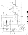
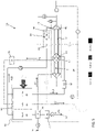
- FIG. 1 a schematic diagram of a portion of an environment control system (ECS) 20, such as a pack for example, is depicted according to non-limiting embodiments.
- ECS environment control system
- the system 20 can receive a first medium A1 at a first inlet 22.
- the first medium A1 is bleed air, which is pressurized air originating from i.e. being "bled" from, an engine or auxiliary power unit of the aircraft. It shall be understood that one or more of the temperature, humidity, and pressure of the bleed air can vary based upon the compressor stage and revolutions per minute of the engine or auxiliary power unit from which the air is drawn.
- the system 20 also receives a second medium A2 at an inlet 24 and may provide a conditioned form of at least one of the first medium A1 and the second medium A2 to a volume 26.
- the second medium A2 is fresh air, such as outside air for example.
- the outside air can be procured via one or more scooping mechanisms, such as an impact scoop or a flush scoop for example.
- the inlet 24 can be considered a fresh or outside air inlet.
- the fresh air A2 described herein is at an ambient pressure equal to an air pressure outside of the aircraft when the aircraft is on the ground, and is between an ambient pressure and a cabin pressure when the aircraft is in flight.
- the system 20 can further receive a third medium A3 at an inlet 26.
- the inlet 26 is operably coupled to a volume 26 is the cabin of an aircraft and the third medium A3 is cabin discharge air, which is air leaving the volume that would typically be discharged overboard.
- the system 20 is configured to extract work from the third medium A3. In this manner, the pressurized air A3 of the volume can be utilized by the system 20 to achieve certain operations.
- the environmental control system 20 includes a RAM air circuit 30 including a shell or duct, illustrated schematically in broken lines at 32, within which one or more heat exchangers are located.
- the shell 32 can receive and direct a medium, such as ram air for example, through a portion of the system 20.
- the one or more heat exchangers are devices built for efficient heat transfer from one medium to another. Examples of the type of heat exchangers that may be used, include, but are not limited to, double pipe, shell and tube, plate, plate and shell, adiabatic shell, plate fin, pillow plate, and fluid heat exchangers.
- the one or more heat exchangers arranged within the shell 32 may be referred to as ram heat exchangers.
- the ram heat exchangers include a first heat exchanger 34, a second heat exchanger 36, and a third heat exchanger 38.
- ram air such as outside air for example, acts as a heat sink to cool a medium passing there through, for example the first medium A1 and/or the second medium A2.
- the system 20 additionally comprises at least one compression device 40.
- the compression device 40 of the system 20 is a mechanical device that includes components for performing thermodynamic work on a medium (e.g., extracts work from or applies work to the first medium A1, the second medium A2, and/or the third medium A3 by raising and/or lowering pressure and by raising and/or lowering temperature).
- Examples of the compression device 40 include an air cycle machine, a three-wheel air cycle machine, a four-wheel air cycle machine, etc.
- the compression device 40 includes a compressor 42, a first turbine 44, a second turbine 46, and a power turbine 48 operably coupled to each other via a shaft 50.
- the compressor 42 is a mechanical device that raises a pressure of a medium and can be driven by another mechanical device (e.g., a motor or a medium via a turbine). Examples of compressor types include centrifugal, diagonal or mixed-flow, axial-flow, reciprocating, ionic liquid piston, rotary screw, rotary vane, scroll, diaphragm, air bubble, etc.
- the compressor 42 is configured to receive and pressurize the second medium A2.
- the first turbine 44, the second turbine 46, and the power turbine 48 are mechanical devices that expand a medium and extract work therefrom (also referred to as extracting energy). In the compression device 40, the turbines 44, 46, and 48 drive the compressor 42 via the shaft 50.
- the system 20 additionally comprises at least one expansion device 52.
- the expansion device 52 is a mechanical device, similar to the compression device 40, and includes components for performing thermodynamic work on a medium (e.g., extracts work from or applies work to the second medium A2 by raising and/or lowering pressure and by raising and/or lowering temperature). Examples of the expansion device 52 include, but are not limited to, a simple air cycle machine or a tip turbine fan etc.
- the expansion device 52 is a two-wheel air cycle machine including a turbine 54 and a fan 56 operably coupled via a shaft 58.
- the turbine 54 is a mechanical device that expands a medium and extracts work therefrom.
- the turbine 54 drives rotation of the fan 56 via the shaft 58.
- the turbine 54 can comprise a nozzle configured to accelerate a medium supplied thereto for entry into a turbine impeller (not shown).
- the fan 56 is a mechanical device that can force via push or pull methods a medium (e.g., ram air) through the shell 32 across the one or more ram heat exchangers 34, 36, 38 and at a variable cooling to control temperatures.
- the system 20 additionally includes a dehumidification system 60.
- the dehumidification system 60 includes a condenser 62 and a water extractor 64 arranged downstream from the condenser 62.
- the condenser 62 and the water extractor 64 are arranged in fluid communication with the first medium A1, and in some embodiments with both the first medium A1 and the second medium A2.
- the condenser 62 is a particular type of heat exchanger and the water collectors 64 is a mechanical device that performs a process of removing water from a medium.
- the dehumidification system 60 includes an additional water extractor 66 associated with the first medium A1 and located at a position upstream from the first turbine 44. Further, operation of the first turbine may contribute to dehumidification of the first medium received therein.
- Valves e.g., flow regulation device or mass flow valve
- Valves are devices that regulate, direct, and/or control a flow of a medium by opening, closing, or partially obstructing various passageways within the tubes, pipes, etc. of the system. Valves can be operated by actuators, such that flow rates of the medium in any portion of the system 20 can be regulated to a desired value.
- a first valve V1 is configured to control a supply of the first medium A1 to the system 20.
- a second valve V2 may be operable to allow a portion of a medium, such as the first medium A1, to bypass the first turbine 44 of the compression device 40.
- operation of the second valve V2 may be used to add heat and to drive the compression device 40 during failure modes.
- the third valve V3 may be operable to allow a portion of the second medium A2 to bypass the expansion device 52, and is therefore configured to control the speed of the ram fan and to provide compressor surge control.
- Operation of a fourth valve V4 is used to control the amount of the second medium entering the condenser for ground and low altitude flight conditions. On moderate temperature days on the ground, the valve V4 may be partially or fully closed. Further, valve V4 is typically closed at altitude.
- the fifth valve V5 is configured to control a supply of a third medium provided to the power turbine 48.
- Valve V6 may be configured to direct a supply of conditioned first medium, downstream from the outlet of the second turbine 46 overboard or to the ram air circuit 30 and valve V7 may be configured to allow a portion of a medium output from the dehumidification system 60 to bypass the second turbine 46 of the compression device 40.
- the system 20 is operable in a plurality of modes, selectable based on a flight condition of the aircraft. For example, the system 20 is operable in a first mode when the aircraft is on the ground or at a low altitude and the system is operable in a second mode when the aircraft is at altitude or in a cruise condition. Operation in a third mode may occur in the event of a failure of a portion of the environmental control system. Similarly, the system may be operable in a fourth mode when 100% fresh air is to be provided to the one or more loads such as the cabin for example.
- each of valves V2, V3, V5 and V7 are in a closed configuration. Accordingly, in the first mode of operation, a supply of the third medium A3 is not provided to the system 20.
- Valve V1 is open and a high temperature, high pressure first medium A1 drawn through the inlet port 22 may pass through an ozone converter, illustrated at 70, before being provided to the first heat exchanger 34.
- the first medium A1 is cooled via a flow of ram air.
- the first medium A1 then passes sequentially from the first heat exchanger 34 to the third heat exchanger 38 where the first medium A1 is cooled to a nearly ambient temperature.
- the process of cooling the first medium in the chiller or third heat exchanger 38 condenses moisture out of the air. Moisture is then removed from the wet first medium A1 within a water extractor 66 of the dehumidification system 60 before being provided to the inlet of the first turbine 44. Within the first turbine 44, the first medium A1 is expanded and work is extracted to power operation of the compressor 42. The additional temperature drop of the first medium that occurs within the first turbine 44 causes moisture within the first medium A1 to condense while maintaining the temperature of the first medium A1 above freezing.
- a supply of second medium A2 drawn from port 24 is compressed within the compressor 42 causing the temperature of the second medium A2 to increase.
- the second medium A2 output from the compressor 42 passes sequentially through an ozone converter 72 and the second heat exchanger 36 to cool the second medium A2 to about an ambient temperature. Downstream from the second heat exchanger 36, the second medium A2 diverts.
- a first portion A2A of the second medium A2 is provided to the turbine 54 of the expansion device 52. Within the turbine 54, the first portion A2A of the second medium A2 is expanded and work is extracted, thereby driving operation of the fan 56 which moves ram air through the ram air circuit 30.
- the first portion A2A of the second medium A2 output from the turbine 54 of the expansion device 52 is then directed to the condenser 62 of the dehumidification system prior to being dumped overboard to ambient or being released into the ram air circuit 30.
- a second portion A2B of the second medium A2 is provided from the second heat exchanger 36 of the ram air circuit 30 directly to the condenser 62 of the dehumidification system 60.
- the second portion A2B of the second medium A2 combines with the first medium A1 output from the first turbine 44, such that a mixture A4 thereof is provided to the condenser 62 and subsequently to the water extractor 64.
- the condenser 62 and the water extractor 64 function as a middle pressure water separator.
- the mixture A4 is arranged in a heat exchanger relationship with the first portion A2A of the second medium A2.
- the mixture A4 is cooled and then moisture is removed therefrom in the water extractor 64.
- the mixture A4 of the first medium A1 and the second portion A2B of the second medium A2 is provided to the second turbine 46 of the compression device 40 where the mixture A4 is expanded and work is extracted, further driving the compressor 42.
- the mixture A4 is provided to one or more loads of the aircraft.
- the output from the second turbine 46 is used to cool the flight deck and cabin.
- the mixture A4 provided to the loads of the aircraft has less than 150 grains of moisture per kg of air (70 grains of moisture per pound of air).
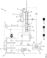
- the system 20 is configured to operate in a second mode when the aircraft is at altitude.
- the second mode of operation is similar to the first mode.
- additional energy is provided to the compressor 42 of the compression device 40 via the supply of third medium A3 is provided to the power turbine 48 of the compression device 40.
- the third medium A3 is heated by the first medium A1 in an outflow heat exchanger, illustrated schematically at 74, prior to being supplied to the power turbine 48.
- the air can be used as a heat sink by dumping the air into the inlet of the ram air circuit 30 or the air can be dumped overboard either directly or via the ram air circuit 30.
- valve V3 is open, thereby allowing the second medium A2 to bypass the expansion device 52 and the fourth valve V4 is closed so that all of the second medium A2 is provided to the one or more loads of the aircraft and used for cooling.
- each of valves V1, V3, and V5 are open, and valves V2, V4, and V7 are closed.
- a high temperature, high pressure first medium A1 drawn through the inlet port 22 passes through the ozone converter 70 before being supplied to the outflow heat exchanger 74.
- the first medium is arranged in a heat exchanger relationship with the third medium A3, such that heat is transferred from the hot first medium A1 to the cooler third medium A3.
- the cooler first medium is then provided to the first heat exchanger 34 and subsequently to the third heat exchanger 38, where the first medium A1 is cooled via a flow of ram air.
- the moisture that has condensed out of the first medium A1 is collected as the first medium A1 passes through the water extractor 66 of the dehumidification system 60 before being provided to the inlet of the first turbine 44.
- the first medium A1 is expanded and work is extracted to power operation of the compressor 42.
- the additional temperature drop of the first medium that occurs within the first turbine 44 causes moisture within the first medium A1 to condense while maintaining the temperature of the first medium A1 above freezing.
- the cool first medium A1 passes through the condenser 62 to the water extractor 64. Because no secondary flow is provided to the condenser in the second mode of operation, the condenser is not an active component of the dehumidification system 60. However, moisture is removed from the first medium A1 within the water extractor 64. From the water extractor 64, the first medium A1 is provided to the second turbine 46 of the compression device 40 where the first medium A1 is expanded and work is extracted. From the outlet of the second turbine 46, the first medium A1 is mixed with the second medium A2 prior to being provided to one or more loads of the system or aircraft.
- a supply of second medium A2 drawn from port 24 is compressed within the compressor 42 causing the temperature of the second medium A2 to increase.
- the second medium A2 output from the compressor 42 passes sequentially through the ozone converter 72 and the second heat exchanger 36 to cool the second medium A2 to about an ambient temperature.
- the flow of the second medium A2 is not divided into multiple paths. Rather, because valve V3 is open, the entirety of the flow of second medium A2 bypasses the expansion device 52 and is provided downstream from the outlet of the second turbine 46 for mixture with the first medium A1 and to be provided to one or more loads of the system or aircraft.
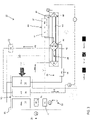
- the system 20 is configured to operate in a third mode during a failure of the environmental control system, such as when only a single ECS pack 20, for example the pack shown in the FIGS., is operational.
- the third mode of operation as illustrated schematically in FIG. 4 , is similar to the second mode; however in the third mode, valve V2 is open.
- a first portion A1A of the output from the first heat exchanger 34 is provided to the third heat exchanger 38 and the remainder of the system 20 in a manner as previously described.
- a second portion A1B of the first medium A1 is configured to bypass the third heat exchanger 38, the water extractor 66 and the first turbine 44.
- the first portion A1A and the second portion A1B of the first medium A1 mix upstream from the dehumidification system 60.
- valve V2 By opening valve V2, the temperature of the first medium A1 provided to the second turbine 46 is increased and more power is provided to the compression device 40 compared to other modes of operation.
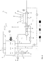
- the system is configured to operate in a fourth mode.
- the fourth mode is a "Fresh air" mode where only fresh air is distributed from the system 20 to one or more downstream loads.
- the fourth mode of operation is similar to the third mode except that in the fourth mode, valve V6 is open.
- the mixture of partially cooled and fully cooled first medium A1 output from the second turbine 46 may be dumped overboard or may be used as a heat sink by dumping the first medium into the ram air circuit 30.
- a first portion A1A of the output from the first heat exchanger 34 is provided to the third heat exchanger 38 and the remainder of the system 20 in a manner as previously described.
- a second portion A1B of the first medium A1 is configured to bypass the third heat exchanger 38, the water extractor 66 and the first turbine 44.
- the first portion A1A and the second portion A1B of the first medium A1 mix upstream from the dehumidification system 60.
- valve V2 By opening valve V2, the temperature of the first medium A1 provided to the second turbine 46 is increased and more power is provided to the compression device 40 compared to other modes of operation.
- a check valve may be arranged within the fluid flow line at a position between the connection of the outlet of the second turbine 46 and the conduit extending from valve V3. The check valve restricts the flow of the first medium there through, while preventing a back flow of the second medium toward the second turbine 46.
Landscapes
- Health & Medical Sciences (AREA)
- General Health & Medical Sciences (AREA)
- Pulmonology (AREA)
- Engineering & Computer Science (AREA)
- Aviation & Aerospace Engineering (AREA)
- Drying Of Gases (AREA)
- Engine Equipment That Uses Special Cycles (AREA)
- Control Of Turbines (AREA)
Claims (13)
- Système de contrôle environnemental d'un aéronef comprenant :un circuit d'air dynamique (30) comportant une enveloppe d'air dynamique (32) à l'intérieur de laquelle sont positionnés un premier échangeur de chaleur (34), un deuxième échangeur de chaleur (36) et un troisième échangeur de chaleur (38), dans lequel le troisième échangeur de chaleur (38) est directement relié à une sortie du premier échangeur de chaleur (34) de sorte qu'un flux d'un premier fluide (A1) est fourni au premier échangeur de chaleur (34) et au troisième échangeur de chaleur (38) en série ;un système de déshumidification (60) comprenant un condenseur (62) et un extracteur d'eau (64) agencé en communication fluidique avec le circuit d'air dynamique ; etun dispositif de compression (40) agencé en communication fluidique avec le circuit d'air dynamique et le système de déshumidification, le dispositif de compression comporte un compresseur (42) et une première turbine (44) couplés l'un à l'autre via un arbre (50), dans lequel, pendant le fonctionnement de la première turbine, de la puissance est extraite du premier fluide (A1) à l'intérieur de la première turbine pour alimenter le compresseur ; etun extracteur d'eau supplémentaire agencé en amont de la première turbine ;dans lequel un deuxième fluide est fourni au compresseur et pendant le fonctionnement du système de contrôle environnemental dans un premier mode, un mélange comportant seulement une partie du deuxième fluide sortant du compresseur et du premier fluide sortant de la première turbine est fourni au système de déshumidification puis à une charge en aval ;et dans lequel pendant le fonctionnement du système de contrôle environnemental dans un deuxième mode, le premier fluide et le deuxième fluide sont mélangés avant d'être distribués à une charge en aval.
- Système de contrôle environnemental selon la revendication 1, dans lequel le dispositif de compression comprend en outre une deuxième turbine (46) agencée en communication fluidique avec le système de déshumidification.
- Système de contrôle environnemental selon la revendication 2, dans lequel lors du fonctionnement du système de contrôle environnemental dans le premier mode, le mélange sortant du système de déshumidification est fourni à la deuxième turbine.
- Système de contrôle environnemental selon la revendication 1, 2 ou 3, dans lequel le système de contrôle environnemental est utilisable dans le premier mode lorsque l'aéronef est au sol ou à basse altitude.
- Système de contrôle environnemental selon la revendication 2 ou 3, comprenant en outre un dispositif de détente (52) situé séparément du dispositif de compression et agencé en communication fluidique avec le circuit d'air dynamique et le système de déshumidification.
- Système de contrôle environnemental selon la revendication 5, dans lequel le dispositif de détente comprend en outre une autre turbine (54) couplée de manière fonctionnelle à un ventilateur (56) par un autre arbre (58), le ventilateur étant situé à l'intérieur de l'enveloppe d'air dynamique de sorte que le fonctionnement du ventilateur déplace l'air à travers le circuit d'air dynamique.
- Système de contrôle environnemental selon la revendication 5 ou 6, dans lequel lors du fonctionnement du système de contrôle environnemental dans le premier mode, une autre partie du deuxième fluide (A2) est fournie au dispositif de détente (52) puis au système de déshumidification (60), dans lequel à l'intérieur du système de déshumidification, une autre partie du deuxième fluide est agencée dans une relation d'échange de chaleur avec le mélange (A4).
- Système de contrôle environnemental selon la revendication 7, dans lequel pendant le fonctionnement du système de contrôle environnemental, une autre partie du deuxième fluide (A2) est émise à partir du système de déshumidification (60) par-dessus bord.
- Système de contrôle environnemental selon la revendication 7, dans lequel pendant le fonctionnement du système de contrôle environnemental, une autre partie du deuxième fluide (A2) est émise à partir du système de déshumidification (60) dans le circuit d'air dynamique (30).
- Système de contrôle environnemental selon la revendication 5 ou l'une quelconque des revendications qui en dépendent, comprenant en outre une première soupape de dérivation associée au dispositif de détente (52), dans lequel pendant le fonctionnement du système de contrôle environnemental dans un deuxième mode, la première soupape de dérivation est ouverte de sorte qu'au moins une partie du deuxième fluide (A2) sortant du compresseur contourne le dispositif de détente et le système de déshumidification (60).
- Système de contrôle environnemental selon la revendication 10, comprenant en outre une seconde soupape de dérivation associée à la première turbine du dispositif de compression, dans lequel pendant le fonctionnement du système de contrôle environnemental dans le troisième mode, la seconde soupape de dérivation est ouverte de sorte qu'au moins une partie du premier fluide (A1) est fournie du circuit d'air dynamique (30) directement au système de déshumidification (60).
- Système de contrôle environnemental selon la revendication 1 ou l'une quelconque des revendications qui en dépendent, dans lequel le dispositif de compression comprend en outre une turbine de puissance (48) couplée à l'arbre, le système de contrôle environnemental pouvant fonctionner dans une pluralité de modes de sorte que dans au moins un mode, un troisième fluide est fourni à la turbine de puissance.
- Système de contrôle environnemental selon la revendication 12, dans lequel le premier fluide (A1) est de l'air de purge, le deuxième fluide (A2) est de l'air frais et le troisième fluide (A3) est de l'air de décharge de cabine.
Applications Claiming Priority (1)
| Application Number | Priority Date | Filing Date | Title |
|---|---|---|---|
| US201862619459P | 2018-01-19 | 2018-01-19 |
Publications (2)
| Publication Number | Publication Date |
|---|---|
| EP3514065A1 EP3514065A1 (fr) | 2019-07-24 |
| EP3514065B1 true EP3514065B1 (fr) | 2023-01-18 |
Family
ID=65138904
Family Applications (1)
| Application Number | Title | Priority Date | Filing Date |
|---|---|---|---|
| EP19152829.8A Active EP3514065B1 (fr) | 2018-01-19 | 2019-01-21 | Système de contrôle environnemental d'un aéronef |
Country Status (2)
| Country | Link |
|---|---|
| US (1) | US11053010B2 (fr) |
| EP (1) | EP3514065B1 (fr) |
Families Citing this family (18)
| Publication number | Priority date | Publication date | Assignee | Title |
|---|---|---|---|---|
| US11192655B2 (en) * | 2017-11-03 | 2021-12-07 | Hamilton Sundstrand Corporation | Regenerative system ECOECS |
| CN110481791B (zh) * | 2019-09-18 | 2020-12-15 | 南京航空航天大学 | 一种飞机座舱空气调节系统 |
| CN111017235B (zh) * | 2019-12-25 | 2021-09-03 | 中国航空工业集团公司沈阳飞机设计研究所 | 一种能量优化的飞机机电系统热管理方法 |
| US11851191B2 (en) | 2020-07-30 | 2023-12-26 | Hamilton Sundstrand Corporation | Aircraft environmental control system |
| EP3945026A1 (fr) | 2020-07-30 | 2022-02-02 | Hamilton Sundstrand Corporation | Système de réglage environnemental d'un aéronef |
| EP3945025A1 (fr) | 2020-07-30 | 2022-02-02 | Hamilton Sundstrand Corporation | Système de réglage environnemental d'un aéronef |
| US11926422B2 (en) | 2021-04-29 | 2024-03-12 | Hamilton Sundstrand Corporation | 100% ambient air environmental control system with bleed turbine in series |
| CN113353267A (zh) * | 2021-07-20 | 2021-09-07 | 南京航空航天大学 | 一种直升机座舱空气调节系统 |
| US11731780B2 (en) | 2021-09-09 | 2023-08-22 | Hamilton Sundstrand Corporation | Aircraft system including a cryogenic fluid operated auxiliary power unit (APU) |
| US20230080053A1 (en) * | 2021-09-10 | 2023-03-16 | Hamilton Sundstrand Corporation | Cryogenic fluid heat exchanger system for an aircraft environmental control system (ecs) |
| US20230234710A1 (en) * | 2022-01-27 | 2023-07-27 | Hamilton Sundstrand Corporation | Environmental control system including humidity sensor |
| US20240043126A1 (en) * | 2022-08-04 | 2024-02-08 | Hamilton Sundstrand Corporation | Ram air cooling power recovery |
| US20240300551A1 (en) * | 2023-03-09 | 2024-09-12 | Hamilton Sundstrand Corporation | Hyperloop environmental control system |
| US20240300548A1 (en) * | 2023-03-09 | 2024-09-12 | Hamilton Sundstrand Corporation | Hyperloop environmental control system |
| US20240300549A1 (en) * | 2023-03-09 | 2024-09-12 | Hamilton Sundstrand Corporation | Hyperloop environmental control system |
| US20240300550A1 (en) * | 2023-03-09 | 2024-09-12 | Hamilton Sundstrand Corporation | Hyperloop environmental control system |
| US20240300552A1 (en) * | 2023-03-09 | 2024-09-12 | Hamilton Sundstrand Corporation | Hyperloop environmental control system |
| US20240300547A1 (en) * | 2023-03-09 | 2024-09-12 | Hamilton Sundstrand Corporation | Hyperloop environmental control system |
Citations (1)
| Publication number | Priority date | Publication date | Assignee | Title |
|---|---|---|---|---|
| EP3489142A2 (fr) * | 2017-11-06 | 2019-05-29 | Hamilton Sundstrand Corporation | Système de commande environnemental d'aéronef avec des turbines à air de prélèvement en série |
Family Cites Families (12)
| Publication number | Priority date | Publication date | Assignee | Title |
|---|---|---|---|---|
| US4261416A (en) | 1979-02-23 | 1981-04-14 | The Boeing Company | Multimode cabin air conditioning system |
| US5442905A (en) | 1994-04-08 | 1995-08-22 | Alliedsignal Inc. | Integrated power and cooling environmental control system |
| US5461882A (en) | 1994-07-22 | 1995-10-31 | United Technologies Corporation | Regenerative condensing cycle |
| US5887445A (en) * | 1997-11-11 | 1999-03-30 | Alliedsignal Inc. | Two spool environmental control system |
| DE19963280C1 (de) | 1999-12-27 | 2001-08-23 | Liebherr Aerospace Gmbh | Klimatisierungssystem für Flugzeugkabinen |
| DE10036443A1 (de) | 2000-07-26 | 2002-04-04 | Liebherr Aerospace Gmbh | Klimatisierungssystem für Flugzeuge |
| DE10234968A1 (de) | 2002-07-31 | 2004-02-12 | Liebherr-Aerospace Lindenberg Gmbh | Flugzeugklimaanlage |
| JP4122925B2 (ja) | 2002-10-22 | 2008-07-23 | 株式会社島津製作所 | 航空機用空気調和装置 |
| US20080110193A1 (en) * | 2006-11-10 | 2008-05-15 | Honeywell International Inc. | Environmental control system with adsorption based water removal |
| US9669936B1 (en) | 2012-10-24 | 2017-06-06 | The Boeing Company | Aircraft air conditioning systems and methods |
| EP2998223B1 (fr) | 2014-09-19 | 2018-12-05 | Airbus Operations GmbH | Système de conditionnement d'air pour aéronef et procédé de fonctionnement d'un système de conditionnement d'air pour aéronef |
| US10604263B2 (en) | 2016-05-26 | 2020-03-31 | Hamilton Sundstrand Corporation | Mixing bleed and ram air using a dual use turbine system |
-
2018
- 2018-05-23 US US15/987,590 patent/US11053010B2/en active Active
-
2019
- 2019-01-21 EP EP19152829.8A patent/EP3514065B1/fr active Active
Patent Citations (1)
| Publication number | Priority date | Publication date | Assignee | Title |
|---|---|---|---|---|
| EP3489142A2 (fr) * | 2017-11-06 | 2019-05-29 | Hamilton Sundstrand Corporation | Système de commande environnemental d'aéronef avec des turbines à air de prélèvement en série |
Also Published As
| Publication number | Publication date |
|---|---|
| US20190225343A1 (en) | 2019-07-25 |
| US11053010B2 (en) | 2021-07-06 |
| EP3514065A1 (fr) | 2019-07-24 |
Similar Documents
| Publication | Publication Date | Title |
|---|---|---|
| EP3514065B1 (fr) | Système de contrôle environnemental d'un aéronef | |
| EP3489142B1 (fr) | Système de commande environnemental d'aéronef avec des turbines à air de prélèvement en série | |
| EP3480113B1 (fr) | Système régénératif ecoecs | |
| EP3354573B1 (fr) | Système de commande environnemental dans un arrangement intégré avec un échangeur de chaleur prélèvement d'air/échappement cabine | |
| EP3354576B1 (fr) | Système avancé de commande environnemental | |
| EP3421364B1 (fr) | Système de contrôle environnemental d'un aéronef à cycle simple et à trois roues | |
| EP3587269B1 (fr) | Système de réglage environnemental d'un aéronef | |
| EP3945031B1 (fr) | Système de réglage environnemental d'un aéronef | |
| EP3354574B1 (fr) | Système de commande environnemental agencé dans un arrangement intégré avec deux échangeurs de chaleur prélèvement d'air/échappement cabine | |
| EP3945026A1 (fr) | Système de réglage environnemental d'un aéronef | |
| EP3760542A1 (fr) | Système de contrôle environnemental d'un aéronef | |
| EP3945029B1 (fr) | Système de réglage environnemental d'un aéronef | |
| EP4082911A1 (fr) | Système de climatisation à 100 % air ambiant avec turbines à prélèvement d'air moteur agencées en série | |
| EP4005925A1 (fr) | Architecture d'air ambiant avec machine à cycle d'air unique et séparateur d'eau haute pression | |
| EP4331991A1 (fr) | Système de contrôle environnemental à faible pression d'entrée | |
| US12097962B2 (en) | Aircraft environmental control system | |
| EP3521169B1 (fr) | Système de commande environnemental d'un aéronef à cycle simple et à trois roues |
Legal Events
| Date | Code | Title | Description |
|---|---|---|---|
| PUAI | Public reference made under article 153(3) epc to a published international application that has entered the european phase |
Free format text: ORIGINAL CODE: 0009012 |
|
| STAA | Information on the status of an ep patent application or granted ep patent |
Free format text: STATUS: THE APPLICATION HAS BEEN PUBLISHED |
|
| AK | Designated contracting states |
Kind code of ref document: A1 Designated state(s): AL AT BE BG CH CY CZ DE DK EE ES FI FR GB GR HR HU IE IS IT LI LT LU LV MC MK MT NL NO PL PT RO RS SE SI SK SM TR |
|
| AX | Request for extension of the european patent |
Extension state: BA ME |
|
| STAA | Information on the status of an ep patent application or granted ep patent |
Free format text: STATUS: REQUEST FOR EXAMINATION WAS MADE |
|
| 17P | Request for examination filed |
Effective date: 20191121 |
|
| RBV | Designated contracting states (corrected) |
Designated state(s): AL AT BE BG CH CY CZ DE DK EE ES FI FR GB GR HR HU IE IS IT LI LT LU LV MC MK MT NL NO PL PT RO RS SE SI SK SM TR |
|
| STAA | Information on the status of an ep patent application or granted ep patent |
Free format text: STATUS: EXAMINATION IS IN PROGRESS |
|
| 17Q | First examination report despatched |
Effective date: 20200504 |
|
| STAA | Information on the status of an ep patent application or granted ep patent |
Free format text: STATUS: EXAMINATION IS IN PROGRESS |
|
| GRAP | Despatch of communication of intention to grant a patent |
Free format text: ORIGINAL CODE: EPIDOSNIGR1 |
|
| STAA | Information on the status of an ep patent application or granted ep patent |
Free format text: STATUS: GRANT OF PATENT IS INTENDED |
|
| INTG | Intention to grant announced |
Effective date: 20220822 |
|
| GRAS | Grant fee paid |
Free format text: ORIGINAL CODE: EPIDOSNIGR3 |
|
| GRAA | (expected) grant |
Free format text: ORIGINAL CODE: 0009210 |
|
| STAA | Information on the status of an ep patent application or granted ep patent |
Free format text: STATUS: THE PATENT HAS BEEN GRANTED |
|
| AK | Designated contracting states |
Kind code of ref document: B1 Designated state(s): AL AT BE BG CH CY CZ DE DK EE ES FI FR GB GR HR HU IE IS IT LI LT LU LV MC MK MT NL NO PL PT RO RS SE SI SK SM TR |
|
| REG | Reference to a national code |
Ref country code: GB Ref legal event code: FG4D |
|
| REG | Reference to a national code |
Ref country code: DE Ref legal event code: R096 Ref document number: 602019024443 Country of ref document: DE |
|
| REG | Reference to a national code |
Ref country code: CH Ref legal event code: EP |
|
| REG | Reference to a national code |
Ref country code: AT Ref legal event code: REF Ref document number: 1544562 Country of ref document: AT Kind code of ref document: T Effective date: 20230215 Ref country code: IE Ref legal event code: FG4D |
|
| REG | Reference to a national code |
Ref country code: LT Ref legal event code: MG9D |
|
| REG | Reference to a national code |
Ref country code: NL Ref legal event code: MP Effective date: 20230118 |
|
| REG | Reference to a national code |
Ref country code: AT Ref legal event code: MK05 Ref document number: 1544562 Country of ref document: AT Kind code of ref document: T Effective date: 20230118 |
|
| P01 | Opt-out of the competence of the unified patent court (upc) registered |
Effective date: 20230522 |
|
| PG25 | Lapsed in a contracting state [announced via postgrant information from national office to epo] |
Ref country code: NL Free format text: LAPSE BECAUSE OF FAILURE TO SUBMIT A TRANSLATION OF THE DESCRIPTION OR TO PAY THE FEE WITHIN THE PRESCRIBED TIME-LIMIT Effective date: 20230118 |
|
| PG25 | Lapsed in a contracting state [announced via postgrant information from national office to epo] |
Ref country code: RS Free format text: LAPSE BECAUSE OF FAILURE TO SUBMIT A TRANSLATION OF THE DESCRIPTION OR TO PAY THE FEE WITHIN THE PRESCRIBED TIME-LIMIT Effective date: 20230118 Ref country code: PT Free format text: LAPSE BECAUSE OF FAILURE TO SUBMIT A TRANSLATION OF THE DESCRIPTION OR TO PAY THE FEE WITHIN THE PRESCRIBED TIME-LIMIT Effective date: 20230518 Ref country code: NO Free format text: LAPSE BECAUSE OF FAILURE TO SUBMIT A TRANSLATION OF THE DESCRIPTION OR TO PAY THE FEE WITHIN THE PRESCRIBED TIME-LIMIT Effective date: 20230418 Ref country code: LV Free format text: LAPSE BECAUSE OF FAILURE TO SUBMIT A TRANSLATION OF THE DESCRIPTION OR TO PAY THE FEE WITHIN THE PRESCRIBED TIME-LIMIT Effective date: 20230118 Ref country code: LT Free format text: LAPSE BECAUSE OF FAILURE TO SUBMIT A TRANSLATION OF THE DESCRIPTION OR TO PAY THE FEE WITHIN THE PRESCRIBED TIME-LIMIT Effective date: 20230118 Ref country code: HR Free format text: LAPSE BECAUSE OF FAILURE TO SUBMIT A TRANSLATION OF THE DESCRIPTION OR TO PAY THE FEE WITHIN THE PRESCRIBED TIME-LIMIT Effective date: 20230118 Ref country code: ES Free format text: LAPSE BECAUSE OF FAILURE TO SUBMIT A TRANSLATION OF THE DESCRIPTION OR TO PAY THE FEE WITHIN THE PRESCRIBED TIME-LIMIT Effective date: 20230118 Ref country code: AT Free format text: LAPSE BECAUSE OF FAILURE TO SUBMIT A TRANSLATION OF THE DESCRIPTION OR TO PAY THE FEE WITHIN THE PRESCRIBED TIME-LIMIT Effective date: 20230118 |
|
| PG25 | Lapsed in a contracting state [announced via postgrant information from national office to epo] |
Ref country code: SE Free format text: LAPSE BECAUSE OF FAILURE TO SUBMIT A TRANSLATION OF THE DESCRIPTION OR TO PAY THE FEE WITHIN THE PRESCRIBED TIME-LIMIT Effective date: 20230118 Ref country code: PL Free format text: LAPSE BECAUSE OF FAILURE TO SUBMIT A TRANSLATION OF THE DESCRIPTION OR TO PAY THE FEE WITHIN THE PRESCRIBED TIME-LIMIT Effective date: 20230118 Ref country code: IS Free format text: LAPSE BECAUSE OF FAILURE TO SUBMIT A TRANSLATION OF THE DESCRIPTION OR TO PAY THE FEE WITHIN THE PRESCRIBED TIME-LIMIT Effective date: 20230518 Ref country code: GR Free format text: LAPSE BECAUSE OF FAILURE TO SUBMIT A TRANSLATION OF THE DESCRIPTION OR TO PAY THE FEE WITHIN THE PRESCRIBED TIME-LIMIT Effective date: 20230419 Ref country code: FI Free format text: LAPSE BECAUSE OF FAILURE TO SUBMIT A TRANSLATION OF THE DESCRIPTION OR TO PAY THE FEE WITHIN THE PRESCRIBED TIME-LIMIT Effective date: 20230118 |
|
| REG | Reference to a national code |
Ref country code: CH Ref legal event code: PL |
|
| PG25 | Lapsed in a contracting state [announced via postgrant information from national office to epo] |
Ref country code: LU Free format text: LAPSE BECAUSE OF NON-PAYMENT OF DUE FEES Effective date: 20230121 |
|
| REG | Reference to a national code |
Ref country code: BE Ref legal event code: MM Effective date: 20230131 |
|
| REG | Reference to a national code |
Ref country code: DE Ref legal event code: R097 Ref document number: 602019024443 Country of ref document: DE |
|
| PG25 | Lapsed in a contracting state [announced via postgrant information from national office to epo] |
Ref country code: SM Free format text: LAPSE BECAUSE OF FAILURE TO SUBMIT A TRANSLATION OF THE DESCRIPTION OR TO PAY THE FEE WITHIN THE PRESCRIBED TIME-LIMIT Effective date: 20230118 Ref country code: RO Free format text: LAPSE BECAUSE OF FAILURE TO SUBMIT A TRANSLATION OF THE DESCRIPTION OR TO PAY THE FEE WITHIN THE PRESCRIBED TIME-LIMIT Effective date: 20230118 Ref country code: MC Free format text: LAPSE BECAUSE OF FAILURE TO SUBMIT A TRANSLATION OF THE DESCRIPTION OR TO PAY THE FEE WITHIN THE PRESCRIBED TIME-LIMIT Effective date: 20230118 Ref country code: LI Free format text: LAPSE BECAUSE OF NON-PAYMENT OF DUE FEES Effective date: 20230131 Ref country code: EE Free format text: LAPSE BECAUSE OF FAILURE TO SUBMIT A TRANSLATION OF THE DESCRIPTION OR TO PAY THE FEE WITHIN THE PRESCRIBED TIME-LIMIT Effective date: 20230118 Ref country code: DK Free format text: LAPSE BECAUSE OF FAILURE TO SUBMIT A TRANSLATION OF THE DESCRIPTION OR TO PAY THE FEE WITHIN THE PRESCRIBED TIME-LIMIT Effective date: 20230118 Ref country code: CZ Free format text: LAPSE BECAUSE OF FAILURE TO SUBMIT A TRANSLATION OF THE DESCRIPTION OR TO PAY THE FEE WITHIN THE PRESCRIBED TIME-LIMIT Effective date: 20230118 Ref country code: CH Free format text: LAPSE BECAUSE OF NON-PAYMENT OF DUE FEES Effective date: 20230131 |
|
| PLBE | No opposition filed within time limit |
Free format text: ORIGINAL CODE: 0009261 |
|
| STAA | Information on the status of an ep patent application or granted ep patent |
Free format text: STATUS: NO OPPOSITION FILED WITHIN TIME LIMIT |
|
| PG25 | Lapsed in a contracting state [announced via postgrant information from national office to epo] |
Ref country code: SK Free format text: LAPSE BECAUSE OF FAILURE TO SUBMIT A TRANSLATION OF THE DESCRIPTION OR TO PAY THE FEE WITHIN THE PRESCRIBED TIME-LIMIT Effective date: 20230118 Ref country code: BE Free format text: LAPSE BECAUSE OF NON-PAYMENT OF DUE FEES Effective date: 20230131 |
|
| 26N | No opposition filed |
Effective date: 20231019 |
|
| PGFP | Annual fee paid to national office [announced via postgrant information from national office to epo] |
Ref country code: GB Payment date: 20231219 Year of fee payment: 6 |
|
| PG25 | Lapsed in a contracting state [announced via postgrant information from national office to epo] |
Ref country code: SI Free format text: LAPSE BECAUSE OF FAILURE TO SUBMIT A TRANSLATION OF THE DESCRIPTION OR TO PAY THE FEE WITHIN THE PRESCRIBED TIME-LIMIT Effective date: 20230118 Ref country code: IE Free format text: LAPSE BECAUSE OF NON-PAYMENT OF DUE FEES Effective date: 20230121 |
|
| PGFP | Annual fee paid to national office [announced via postgrant information from national office to epo] |
Ref country code: FR Payment date: 20231219 Year of fee payment: 6 |
|
| PGFP | Annual fee paid to national office [announced via postgrant information from national office to epo] |
Ref country code: DE Payment date: 20231219 Year of fee payment: 6 |
|
| PG25 | Lapsed in a contracting state [announced via postgrant information from national office to epo] |
Ref country code: IT Free format text: LAPSE BECAUSE OF FAILURE TO SUBMIT A TRANSLATION OF THE DESCRIPTION OR TO PAY THE FEE WITHIN THE PRESCRIBED TIME-LIMIT Effective date: 20230118 |