EP3514036A1 - Bogie assembly and straddle-type monorail vehicle having same - Google Patents
Bogie assembly and straddle-type monorail vehicle having same Download PDFInfo
- Publication number
- EP3514036A1 EP3514036A1 EP17852082.1A EP17852082A EP3514036A1 EP 3514036 A1 EP3514036 A1 EP 3514036A1 EP 17852082 A EP17852082 A EP 17852082A EP 3514036 A1 EP3514036 A1 EP 3514036A1
- Authority
- EP
- European Patent Office
- Prior art keywords
- bogie
- traction
- assembly according
- frame
- pin
- Prior art date
- Legal status (The legal status is an assumption and is not a legal conclusion. Google has not performed a legal analysis and makes no representation as to the accuracy of the status listed.)
- Withdrawn
Links
- 239000003638 chemical reducing agent Substances 0.000 claims abstract description 44
- 239000000725 suspension Substances 0.000 claims description 57
- 230000035939 shock Effects 0.000 claims description 50
- 230000007246 mechanism Effects 0.000 claims description 32
- 239000006096 absorbing agent Substances 0.000 claims description 28
- 229910000831 Steel Inorganic materials 0.000 claims description 16
- 239000010959 steel Substances 0.000 claims description 16
- 238000000638 solvent extraction Methods 0.000 claims description 13
- 238000010586 diagram Methods 0.000 description 10
- 230000000087 stabilizing effect Effects 0.000 description 9
- 238000004134 energy conservation Methods 0.000 description 6
- 230000007613 environmental effect Effects 0.000 description 6
- 238000000034 method Methods 0.000 description 6
- 230000008569 process Effects 0.000 description 5
- 230000003014 reinforcing effect Effects 0.000 description 5
- 238000005516 engineering process Methods 0.000 description 4
- 238000003466 welding Methods 0.000 description 3
- 239000000463 material Substances 0.000 description 2
- 230000002159 abnormal effect Effects 0.000 description 1
- 238000010521 absorption reaction Methods 0.000 description 1
- 230000005540 biological transmission Effects 0.000 description 1
- 230000015572 biosynthetic process Effects 0.000 description 1
- 230000003139 buffering effect Effects 0.000 description 1
- 238000004891 communication Methods 0.000 description 1
- 239000004020 conductor Substances 0.000 description 1
- 230000008094 contradictory effect Effects 0.000 description 1
- 230000000694 effects Effects 0.000 description 1
- 238000005265 energy consumption Methods 0.000 description 1
- 230000006872 improvement Effects 0.000 description 1
- 230000003993 interaction Effects 0.000 description 1
- 238000004519 manufacturing process Methods 0.000 description 1
- 239000002184 metal Substances 0.000 description 1
- 230000004048 modification Effects 0.000 description 1
- 238000012986 modification Methods 0.000 description 1
- 230000009467 reduction Effects 0.000 description 1
- 230000007704 transition Effects 0.000 description 1
Images







Classifications
-
- B—PERFORMING OPERATIONS; TRANSPORTING
- B61—RAILWAYS
- B61B—RAILWAY SYSTEMS; EQUIPMENT THEREFOR NOT OTHERWISE PROVIDED FOR
- B61B13/00—Other railway systems
- B61B13/04—Monorail systems
-
- B—PERFORMING OPERATIONS; TRANSPORTING
- B61—RAILWAYS
- B61C—LOCOMOTIVES; MOTOR RAILCARS
- B61C3/00—Electric locomotives or railcars
-
- B—PERFORMING OPERATIONS; TRANSPORTING
- B61—RAILWAYS
- B61C—LOCOMOTIVES; MOTOR RAILCARS
- B61C9/00—Locomotives or motor railcars characterised by the type of transmission system used; Transmission systems specially adapted for locomotives or motor railcars
- B61C9/38—Transmission systems in or for locomotives or motor railcars with electric motor propulsion
- B61C9/48—Transmission systems in or for locomotives or motor railcars with electric motor propulsion with motors supported on vehicle frames and driving axles, e.g. axle or nose suspension
- B61C9/50—Transmission systems in or for locomotives or motor railcars with electric motor propulsion with motors supported on vehicle frames and driving axles, e.g. axle or nose suspension in bogies
-
- B—PERFORMING OPERATIONS; TRANSPORTING
- B61—RAILWAYS
- B61F—RAIL VEHICLE SUSPENSIONS, e.g. UNDERFRAMES, BOGIES OR ARRANGEMENTS OF WHEEL AXLES; RAIL VEHICLES FOR USE ON TRACKS OF DIFFERENT WIDTH; PREVENTING DERAILING OF RAIL VEHICLES; WHEEL GUARDS, OBSTRUCTION REMOVERS OR THE LIKE FOR RAIL VEHICLES
- B61F5/00—Constructional details of bogies; Connections between bogies and vehicle underframes; Arrangements or devices for adjusting or allowing self-adjustment of wheel axles or bogies when rounding curves
- B61F5/02—Arrangements permitting limited transverse relative movements between vehicle underframe or bolster and bogie; Connections between underframes and bogies
- B61F5/04—Bolster supports or mountings
- B61F5/10—Bolster supports or mountings incorporating fluid springs
-
- B—PERFORMING OPERATIONS; TRANSPORTING
- B61—RAILWAYS
- B61F—RAIL VEHICLE SUSPENSIONS, e.g. UNDERFRAMES, BOGIES OR ARRANGEMENTS OF WHEEL AXLES; RAIL VEHICLES FOR USE ON TRACKS OF DIFFERENT WIDTH; PREVENTING DERAILING OF RAIL VEHICLES; WHEEL GUARDS, OBSTRUCTION REMOVERS OR THE LIKE FOR RAIL VEHICLES
- B61F5/00—Constructional details of bogies; Connections between bogies and vehicle underframes; Arrangements or devices for adjusting or allowing self-adjustment of wheel axles or bogies when rounding curves
- B61F5/02—Arrangements permitting limited transverse relative movements between vehicle underframe or bolster and bogie; Connections between underframes and bogies
- B61F5/22—Guiding of the vehicle underframes with respect to the bogies
-
- B—PERFORMING OPERATIONS; TRANSPORTING
- B61—RAILWAYS
- B61H—BRAKES OR OTHER RETARDING DEVICES SPECIALLY ADAPTED FOR RAIL VEHICLES; ARRANGEMENT OR DISPOSITION THEREOF IN RAIL VEHICLES
- B61H5/00—Applications or arrangements of brakes with substantially radial braking surfaces pressed together in axial direction, e.g. disc brakes
-
- Y—GENERAL TAGGING OF NEW TECHNOLOGICAL DEVELOPMENTS; GENERAL TAGGING OF CROSS-SECTIONAL TECHNOLOGIES SPANNING OVER SEVERAL SECTIONS OF THE IPC; TECHNICAL SUBJECTS COVERED BY FORMER USPC CROSS-REFERENCE ART COLLECTIONS [XRACs] AND DIGESTS
- Y02—TECHNOLOGIES OR APPLICATIONS FOR MITIGATION OR ADAPTATION AGAINST CLIMATE CHANGE
- Y02T—CLIMATE CHANGE MITIGATION TECHNOLOGIES RELATED TO TRANSPORTATION
- Y02T30/00—Transportation of goods or passengers via railways, e.g. energy recovery or reducing air resistance
Definitions
- the present disclosure belongs to the field of vehicle manufacturing technology, and in particular relates to a bogie assembly and a straddle-type monorail vehicle with the bogie assembly.
- the laying cost of a straddle-type monorail transportation system is much lower than that of a subway transportation system, and its application scope is wider.
- An electric assembly is an important part of a straddle-type monorail vehicle.
- the reduction ratio of the electric assembly in the related technology is small, such that the electric assembly can only use a motor with low rotating speed, and the energy utilization efficiency of the motor with low rotating speed is relatively low.
- the electric assembly in the related technology occupies a large space and cannot realize a low floor structure.
- the mass of the whole vehicle is larger, the energy consumption is higher, it is not conducive to energy conservation and environmental protection, and there is a space for improvement.
- the present disclosure aims at resolving one of technical problems in related technologies at least to some extent. For this reason, one purpose of the present disclosure is to provide a bogie assembly with a compact structure and high energy efficiency.
- Another purpose of the present disclosure is to provide a straddle-type monorail vehicle with the bogie assembly.
- the bogie assembly comprises: a bogie frame; an electric assembly, the electric assembly being mounted on the bogie frame, the electric assembly comprising a traction motor, a gear reducer and a planetary wheel-side reducer, the traction motor being connected with an input shaft of the gear reducer, and an output shaft of the gear reducer being connected with an input end of the planetary wheel-side reducer; and a walking wheel, the walking wheel being mounted on the bogie frame and an output end of the planetary wheel-side reducer being connected with a hub of the walking wheel.
- the bogie assembly according to the embodiment in the first aspect of the present disclosure adopts a driving solution of integrally mounting the traction motor, the gear reducer, the planetary wheel-side reducer, the hub and the like, the overall structure is simple, the occupied space is small, a low floor structure can be realized, the weight is light, the energy utilization ratio is high and it is conducive to energy conservation and environmental protection.
- the bogie assembly may further have the following additional technical features:
- the electric assembly further comprises: a brake, the brake being disposed between the traction motor and the walking wheel.
- the brake is mounted between the gear reducer and the hub of the walking wheel.
- the brake comprises: a brake disc, the brake disc being connected with the hub of the walking wheel; brake calipers, the brake calipers being connected with a box body of the gear reducer; and a brake driving unit, the brake driving unit being used for driving the brake calipers.
- the electric assembly is disposed on the inner side of the bogie frame.
- the traction motor is transversely disposed.
- the traction motor is connected with the box body of the gear reducer and the box body of the gear reducer is connected with the bogie frame.
- the bogie frame further comprises a traction mechanism comprising: a traction frame, the traction frame straddling the bogie frame along a front-rear direction; and a traction pin assembly, the traction pin assembly being connected with the traction frame and adapted to be connected with a vehicle body.
- the traction pin assembly comprises: a pin shaft, the pin shaft being connected with the top wall of the traction frame, the upper end of the pin shaft being provided with a flange and the flange being adapted to be connected with the vehicle body.
- the top wall of the traction frame is provided with a mounting hole
- the pin shaft has a threaded segment
- the pin shaft penetrates through the mounting hole and the threaded segment is fixed through a nut.
- the traction pin assembly further comprises: a bushing, the bushing being sleeved over the pin shaft; an upper shock absorbing pad, the upper shock absorbing pad being clamped between the flange and the upper surface of the top wall of the traction frame; and a lower shock absorbing pad, the lower shock absorbing pad being clamped between the nut and the lower surface of the top wall of the traction frame.
- the bushing comprises an outer steel bushing, an inner steel bushing and a buffer bushing between the outer steel bushing and the inner steel bushing.
- the traction pin assembly comprises: a pin shaft, the pin shaft being connected with the top wall of the traction frame; and a vehicle body connecting member, the vehicle body connecting member being arranged such that the rigidity in a front-rear direction is greater than the rigidity in the left-right direction, and comprising: a pin bushing mounting seat, the pin bushing mounting seat being adapted to be connected with the vehicle body; and a pin bushing, the pin bushing being connected with the pin bushing mounting seat and sleeved over the pin shaft.
- the pin bushing mounting seat comprises: a fixing cylinder, the fixing cylinder being sleeved over the pin bushing and a buffer member being arranged between the fixing cylinder and the pin bushing; and a mounting plate, the mounting plate being connected with the fixing cylinder and adapted to be connected with the vehicle body.
- the fixing cylinder and the buffer member respectively have an elliptical horizontal section, moreover the long axis of the elliptical horizontal section is oriented along the front-rear direction, and the short axis of the elliptical horizontal section is oriented along the left-right direction.
- a gap is provided in the buffer member and the gap is located on the left side or the right side of the pin shaft.
- the number of the gaps is two and the two gaps are respectively located on the left side and the right side of the pin shaft.
- the horizontal section of the gap is arch-shaped and comprises a first segment, a second segment and a third segment sequentially connected along the front-rear direction, the second segment is rectangular, the long side of the second segment faces the pin bushing, the first segment is an arc-shaped segment extending from the short side of the second segment to the edge of the buffer member, and the first segment and the third segment are symmetrically arranged.
- the buffer member comprises a plurality of sub-buffer members.
- the buffer member is partitioned into four sub-buffer members by two parallel partitioning planes and the pin bushing, the normal of each partitioning plane is oriented along the front-rear direction, and each partitioning plane is intersected with the pin bushing.
- a gap is provided in the buffer member, the gap divides the sub-buffer member between the two partitioning planes into two portions, the portion, close to the pin bushing, in the two portions is fixedly connected with the pin bushing, and the portion, close to the fixing cylinder, in the two portions is fixedly connected with the fixing cylinder.
- the traction frame is arch-shaped and covers a position above the walking wheel.
- the traction frame comprises: a top wall; and two sidewalls, the upper ends of the two sidewalls being respectively connected with the front end and the rear end of the top wall, the lower end of each sidewall being provided with a plurality of fixing seats used for being connected with the bogie frame such that the traction frame is adapted to straddle the bogie frame along the front-rear direction, the plurality of fixing seats at the lower end of the same sidewall comprising a first fixing seat and a second fixing seat, and the bottom surface of the first fixing seat and the bottom surface of the second fixing seat being located on different horizontal planes.
- the position between the first fixing seat and the corresponding second fixing seat is hollowed out to form a lightening hole.
- the width of the sidewalls is gradually increased from top to bottom.
- the top wall is flat and the sidewalls are arc-shaped.
- the sidewall comprises a plurality of sequentially connected arc-shaped segments.
- the bogie assembly further comprises a suspension system comprising: a suspension mounting seat, the suspension mounting seat being adapted to be connected with the vehicle body; a transverse shock absorber, the transverse shock absorber being connected between the suspension mounting seat and the bogie frame; a longitudinal shock absorber, the longitudinal shock absorber being connected between the suspension mounting seat and the bogie frame; and an elastic member, the elastic member being connected between the suspension mounting seat and the bogie frame.
- a suspension system comprising: a suspension mounting seat, the suspension mounting seat being adapted to be connected with the vehicle body; a transverse shock absorber, the transverse shock absorber being connected between the suspension mounting seat and the bogie frame; a longitudinal shock absorber, the longitudinal shock absorber being connected between the suspension mounting seat and the bogie frame; and an elastic member, the elastic member being connected between the suspension mounting seat and the bogie frame.
- the straddle-type monorail vehicle according to the embodiment of the second aspect of the present disclosure comprises the bogie assembly according to the embodiment of the first aspect of the present disclosure.
- the straddle-type monorail vehicle according to the embodiment of the present disclosure has the same advantages as the bogie assembly according to the embodiment of the present disclosure relative to the prior art, which will not be repetitively described here.
- references such as reference terms “an embodiment”, “some embodiments”, “example”, “specific example”, or “some examples” intend to indicate that specific features, structures, materials, or characteristics described with reference to embodiments or examples are included in at least one embodiment or example of the present disclosure.
- schematic descriptions of the foregoing terms do not need to aim at a same embodiment or example.
- the specific features, the structures, the materials or the characteristics that are described may be combined in a proper manner in any one or more embodiments or examples.
- persons skilled in the art can combine or group different embodiments or examples that are described in this specification and features of the different embodiments or examples.
- front-rear direction and “longitudinal” are the running directions of the straddle-type monorail vehicle, i.e., the extending direction of the rail girder 2000
- left-right direction is perpendicular to the running direction of the straddle-type monorail vehicle
- left-right direction is the “transverse direction” of the straddle-type monorail vehicle
- upper-lower direction is the upper-lower direction in the conventional concept
- inside refers to a position close to the rail girder 2000
- outside refers to a position far away from the rail girder 2000.
- the bogie assembly 1000 comprises a bogie frame 100, a traction mechanism 200, a walking wheel 300, guide wheels 400, stabilizing wheels 500, an electric assembly 600 and a suspension system 700.
- the bogie frame 100 is provided with a rail concave portion for straddling the rail girder 2000.
- the traction mechanism 200, the walking wheel 300, the guide wheels 400, the stabilizing wheels 500, the electric assembly 600 and the suspension system 700 are all mounted on the bogie frame 100.
- the suspension system 700 is supported between the bogie frame 100 and the vehicle body of the straddle-type monorail vehicle.
- the electric assembly 600 is used to drive the walking wheel 300 to move along the walking surface of the rail girder 2000.
- the traction mechanism 200 is connected between the bogie frame 100 and the vehicle body of the straddle-type monorail vehicle.
- the traction mechanism 200 is used to transfer the power of the walking wheel 300 to the vehicle body.
- the guide wheels 400 and the stabilizing wheels 500 clamp the sidewalls of the rail girder 2000.
- the walking wheel 300, the guide wheels 400 and the stabilizing wheels 500 according to the embodiment of the present disclosure will be described below with reference to the drawings.
- the walking wheel 300 runs along the walking surface (upper surface) of the rail girder 2000.
- the number of the walking wheel 300 is at least one, and the rotating axis of the walking wheel 300 is in parallel with the walking surface of the rail girder 2000.
- the walking wheel 300 may comprise a rubber tire, such that the shock-proof performance of the straddle-type monorail vehicle is better.
- the walking wheel 300 may also be a steel wheel.
- the bogie assembly 1000 may be provided with two pairs of guide wheels 400, the two pairs of guide wheels 400 are spaced apart along the front-rear direction, each pair of guide wheels 400 comprises two guide wheels 400, the two guide wheels 400 are symmetrically arranged with respect to the rail girder 2000, and the two guide wheels 400 are respectively in contact with one sidewall of the rail girder 2000.
- the distance between the rotating axes of the two guide wheels 400 in the same pair of guide wheels 400 and the rotating axis of the walking wheel 300 is equal.
- the number of the stabilizing wheels 500 is at least two.
- the two stabilizing wheels 500 are symmetrically arranged with respect to the rail girder 2000.
- the two stabilizing wheels 500 are respectively in contact with one sidewall of the rail girder 2000, and the rotating axis of each stabilizing wheel 500 is perpendicular to the rotating axis of the walking wheel 300.
- the traction mechanism 200 comprises a traction frame 210 and a traction pin assembly 220, the traction frame 210 is connected with the frame body 110 of the bogie frame 100, the traction pin assembly 220 is connected with the traction frame 210, and the traction pin assembly 220 is adapted to be connected with the vehicle body.
- the traction force is transmitted successively through the bogie frame 100, the traction frame 210, the traction pin assembly 220 and the vehicle body.
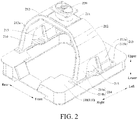
- the traction frame 210 according to the embodiment of the present disclosure will be described firstly with reference to Fig. 2 .
- the traction frame 210 comprises a top wall 211, sidewalls 212 and fixing seats.
- two sidewalls 212 are provided.
- the upper ends of the two sidewalls 212 are respectively connected with the front end of the top wall 211 and the rear end of the top wall 211.
- the lower end of each sidewall 212 is provided with a plurality of fixing seats, the fixing seats are used for being connected with the frame body 110.
- the plurality of fixing seats connected below the two sidewalls 212 is respectively connected with the front arm and rear arm of the frame body 110, that is, the plurality of fixing seats below one sidewall 212 is connected with the front arm of the frame body 110, and plurality of fixing seats below the other sidewall 212 is connected with the rear arm of the frame body 110, such that the traction frame 210 is adapted to straddling the bogie frame 100 along the front-rear direction.
- the rigidity of the traction frame 210 in the front-rear direction is greater than that in the left-right direction, and it helps the traction frame 210 to transfer the traction force in the front-rear direction.
- the plurality of fixing seats at the lower end of the same sidewall 212 comprises a first fixing seat 213 and a second fixing seat 214
- the first fixing seat 213 and the second fixing seat 214 are disposed at an interval along the left-right direction
- the heights of the left half segment and right half segment of each of the front arm and rear arm of the frame body 110 are different
- the left half segment and the right half segment are connected by an arc-shaped segment, such that the strength of the bogie frame 100 is higher.
- the bottom surface of the first fixing seat 213 and the bottom surface of the second fixing seat 214 are located on different horizontal planes to fit with the frame body 110 of the bogie frame 100.
- the mounting strength of the traction frame 210 is high, and the fitting with the bogie frame 100 is better and it helps to realize better transfer of the traction force.
- the traction frame 210 by providing a plurality of fixing seats at different heights, it helps the traction frame 210 to fit with the bogie frame 100, the strength of the traction frame 210 is high, it can bear larger traction force, and the traction process is stable and reliable.
- the sidewalls 212 and the top wall 211 of the traction frame 210 may be jointly formed as an arch-shaped structure, the traction frame 210 is adapted to cover a position above the walking wheel 300, the top wall 211 may be flat, the top wall 211 is adapted to be connected with the vehicle body, and the sidewalls 212 may be arc-shaped.
- the sidewall 212 comprises a plurality of sequentially connected arc-shaped segments, and the width of the sidewall 212 is gradually increased from top to bottom, such that the strength of the traction frame 210 is higher and the traction stability is higher.
- the edges of the left and right sides of the sidewall 212 may be provided with reinforcing ribs 212a to enhance the strength of the sidewall 212.
- the front edge and the rear edge of the right side of the sidewall 212 respectively extend transversely outwards (i.e., towards the right) to form the reinforcing ribs 212a, and the formation method of the reinforcing ribs 212a of the edges of the left side of the sidewall 212 is the same as that of the right side.
- a position between the first fixing seat 213 and the corresponding second fixing seat 214 may be hollowed out to form a lightening hole 215.
- the weight of the traction frame 210 can be reduced, and the lightweight level of the traction frame 210 can be improved.
- the first fixing seat 213 may comprise a first connecting arm 213a and a first mounting plate 213b, the first connecting arm 213a is connected with the corresponding sidewall 212, and the first mounting plate 213b is connected with the first connecting arm 213a.
- the upper end of the first connecting arm 213a is connected with the corresponding sidewall 212
- the lower end of the first connecting arm 213a is connected with the corresponding first mounting plate 213b.
- the first connecting arm 213a can be connected with the first mounting plate 213b through welding.
- the first mounting plate 213b is adapted to be connected with the bogie frame 100.
- the first mounting plate 213b may be provided with a plurality of mounting holes, and threaded fastening members penetrate through the mounting holes and are connected with the frame body 110 of the bogie frame 100, so as to connect the first mounting plate 213b to the bogie frame 100.
- the second fixing seat 214 may comprise a second connecting arm 214a and a second mounting plate 214b, the second connecting arm 214a is connected with the corresponding sidewall 212, and the second mounting plate 214b is connected with the second connecting arm 214a.
- the upper end of the second connecting arm 214a is connected with the corresponding sidewall 212
- the lower end of the second connecting arm 214a is connected with the corresponding second mounting plate 214b.
- the second connecting arm 214a may be connected with the second mounting plate 214b through welding.
- the second mounting plate 214b is adapted to be connected with the bogie frame 100.
- the second mounting plate 214b may be provided with a plurality of mounting holes, and threaded fastening members penetrate through the mounting holes and are connected with the frame body 110 of the bogie frame 100, so as to connect the second mounting plate 214b to the bogie frame 100.
- the first connecting arm 213a and the second connecting arm 214a are respectively and integrally molded with the corresponding sidewalls 212, that is, the first connecting arm 213a is integrally molded with the corresponding sidewall 212, and the second connecting arm 214a is also integrally molded with the corresponding sidewall 212.
- the reinforcing rib 212a may extend from the edge of the sidewall 212 to the edge of the outer side of the first connecting arm 213a (i.e. the edge of the left side), the edge of the outer side of the second connecting arm 214a (i.e. the edge of the right side) and the edge of the lower side of the top wall 211.
- the embodiment of the present disclosure further discloses a bogie assembly 1000.
- the bogie assembly 1000 according to the embodiment of the present disclosure is provided with the traction frame 210 described in any one of the above-mentioned embodiments, and the traction frame 210 is connected with the bogie frame 100.
- the traction force of the bogie assembly 1000 according to the embodiment of the present disclosure is transferred stably, and it can bear a larger driving force.
- the embodiment of the present disclosure further discloses a straddle-type monorail vehicle.
- the straddle-type monorail vehicle according to the embodiment of the present disclosure is provided with the bogie assembly 1000 described in any one of the above-mentioned embodiments, and the traction frame 210 of the bogie assembly 1000 is connected with the vehicle body of the straddle-type monorail vehicle.
- the straddle-type monorail vehicle according to the embodiment of the present disclosure can transfer traction force stably.
- the traction pin assembly 220 according to the embodiment of the present disclosure will be described below with reference to Figs. 2 to 6 .
- the traction pin assembly 220 comprises a pin shaft 221 and a vehicle body connecting member, the pin shaft 221 is connected with the traction frame 210 and the vehicle body connecting member, the vehicle body connecting member is adapted to be connected with the vehicle body, and the vehicle body connecting member is configured such that the rigidity in the front-rear direction is greater than the rigidity in the left-right direction.
- the traction force is mainly transferred along the front-rear direction, and the traction force is transferred from the traction frame 210 to the vehicle body through the pin shaft 221 and the vehicle body connecting member.
- the vehicle body connecting member By configuring the vehicle body connecting member such that the rigidity in the front-rear direction is greater than the rigidity in the left-right direction, the vehicle body connecting member can be prevented from being damaged, the traction is more stable and the stress concentration can be avoided during steering.
- the vehicle body connecting member may comprise a pin bushing mounting seat and a pin bushing 222.
- the pin bushing 222 is connected with the pin bushing mounting seat, and the pin bushing mounting seat is adapted to be connected with the vehicle body.
- the pin bushing mounting seat may comprise a fixing cylinder 223 and a mounting plate 224, the mounting plate 224 is connected with the fixing cylinder 223, the fixing cylinder 223 may be sleeved over the pin bushing 222, and a buffer member 225 is arranged between the fixing cylinder 223 and the pin bushing 222.
- One end of the pin shaft 221 is fixedly connected onto the top wall 211 of the traction frame 210.
- the pin shaft 221 may be connected with the top wall 211 of the traction frame 210 through welding, and the pin bushing 222 is sleeved over the pin shaft 221, and the pin bushing 222 may be in interference fit with the pin shaft 221, such that the pin bushing 222 and the pin shaft 221 are not easily worn and do not produce abnormal noise.
- the mounting plate 224 is adapted to be connected with the vehicle body.
- the mounting plate 224 may be connected with the vehicle body through threaded fastening members.
- the mounting plate 224 may surround the fixing cylinder 223 along the circumferential wall of the fixing cylinder 223, that is, the fixing cylinder 223 may penetrate through the mounting plate 224, and the height of the portion, above the mounting plate 224, of the fixing cylinder 223 is smaller than that below the mounting plate 224.
- the portion, above the mounting plate 224, of the fixing cylinder 223 may be fit with the concave portion on the vehicle body to realize the positioning between the mounting plate 224 and the vehicle body.
- the traction force is sequentially transmitted between the traction frame 210, the pin shaft 221, the pin bushing 222, the buffer member 225, the fixing cylinder 223 and the mounting plate 224, and then is transferred to the vehicle body to achieve traction of the vehicle body.
- the noise during traction force transfer is low, the traction is stable, and it can bear a larger traction force.
- the fixing cylinder 223 may have an elliptical horizontal section, and the long axis of the elliptical horizontal section is oriented along the front-rear direction, the short axis of the elliptical horizontal section is oriented along the left-right direction, the buffer member 225 has an elliptical horizontal section, and the long axis of the elliptical horizontal section is oriented along the front-rear direction, and the short axis of the elliptical horizontal section is oriented along the left-right direction.
- the rigidity of the vehicle body connecting member in the front-rear direction can be enabled to be greater than that in the left-right direction, moreover the buffer member 225 can absorb more shock in the front-rear direction, and thus the shock-proof performance of the traction mechanism 200 is better.
- a gap 226 is provided in the buffer member 225, the gap 226 may be located on the left side or right side of the pin bushing 222.
- the number of the gaps 226 may be two, the two gaps 226 may be respectively located on the left side and right side of the pin bushing 222, the two gaps 226 may be symmetrically arranged with respect to a symmetry plane, the normal of the symmetry plane is oriented along the left-right direction, and the central axis of the pin bushing 222 is in the symmetry plane.
- the traction force is mainly transferred along the front-rear direction, and the shock impact is mainly from the front-rear direction.
- the mass of the traction mechanism 200 can be reduced, the rigidity of the vehicle body connecting member in the left-right direction can be reduced, and the connection strength of the vehicle body connecting member in the left-right direction can be increased.
- the horizontal section of the gap 226 may be arch-shaped.
- the gap 226 comprises a first segment 226a, a second segment 226b and a third segment 226c sequentially connected along the front-back direction.
- the second segment 226b is rectangular, and the long side of the rectangular second segment 226b faces the pin bushing 222.
- the first segment 226a is an arc-shaped segment extending from the short side of the second segment 226b to the edge of the buffer member 225, and the first segment 226a and the third segment 226c are symmetrically arranged.
- the buffer member 225 may include a plurality of sub-buffer members. As illustrated in Fig. 4 , the buffer member 225 is divided into four sub-buffer members 225a, 225b, 225c and 225d by two parallel partitioning planes 225e and the pin bushing 222. The normal of the partitioning planes 225e is oriented along the front-rear direction, and the two partitioning planes 225e are intersected with the pin bushing 222.
- the sub-buffer member 225a and the sub-buffer member 225c are symmetrically arranged, the sub-buffer member 225b and the sub-buffer member 225d are symmetrically arranged, and the sub-buffer member 225b and the sub-buffer member 225d are located between the two partitioning planes 225e.
- the two gaps 226 respectively divide the sub-buffer member 225b and the sub-buffer member 225d into two portions, the portion, close to the pin bushing 222, in the two portions is fixedly connected with the pin bushing 222, and the portion, close to the fixing cylinder 223, in the two portions is fixedly connected with the fixing cylinder 223.
- the buffer member 225 may be a rubber member
- the pin bushing 222 and the fixing cylinder 223 may be metal members
- the buffer member 225 may be respectively vulcanized with the pin bushing 222 and the fixing cylinder 223.
- the traction pin assembly 220 may comprise a pin shaft 221, and the pin shaft 221 is connected to the top wall 211 of the traction frame 210.
- the top wall 211 of the traction frame 210 may be provided with a mounting hole
- the lower end of the pin shaft 221 may have a threaded segment 221b
- the pin shaft 221 penetrates through the mounting hole
- the threaded segment 221b is fixed through a nut 229a.
- the nut 229a may be located below the top wall 211 of the traction frame 210, and a gasket 229b may be clamped between the nut 229a and the top wall 211 of the traction frame 210.
- the upper end of the pin shaft 221 may be provided with a flange 221a, and the flange 221a is adapted to be connected with the vehicle body through threaded fastening members.
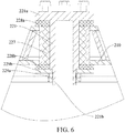
- the traction pin assembly 220 may further comprise an upper shock absorbing pad 228a and a lower shock absorbing pad 228b, the upper shock absorbing pad 228a may be clamped between the flange 221a and the upper surface of the top wall 211 of the traction frame 210, and the lower shock absorbing pad 228b may be clamped between the nut 229a and the lower surface of the top wall 211. Specifically, the lower shock absorbing pad 228b may be clamped between the lower surface of the top wall 211 and the gasket 229b.
- both the upper shock absorbing pad 228a and the lower shock absorbing pad 228b may be rubber members.
- the traction pin assembly 220 may further comprise a bushing 227, the bushing 227 is sleeved over the pin shaft 221, and the length of the bushing 227 may be the same as the thickness of the top wall 211 of the traction frame 210.
- the bushing 227 may comprise a plurality of layers, such as an outer steel bushing, an inner steel bushing and a buffer bushing.
- the buffer bushing is located between the outer steel bushing and the inner steel bushing, and the buffer bushing may be a rubber member.
- the outer steel bushing may be in interference fit with the mounting hole in the top wall 211 of the traction frame 210, the inner steel bushing is sleeved over the pin shaft 221, and the inner steel bushing may be in interference fit with the pin shaft 221.
- the traction mechanism 200 according to the embodiment of the present disclosure comprises the traction frame 210 according to any one of the above-mentioned embodiments and the traction pin assembly 220 according to any one of the above-mentioned embodiments, such that the strength of the traction mechanism 200 is high, it can bear a larger traction force, the traction process is stable and reliable, and the noise is low.
- the embodiment of the present disclosure further discloses a bogie assembly 1000.
- the bogie assembly 1000 according to the embodiment of the present disclosure is provided with the traction mechanism 200 described in any one of the above-mentioned embodiments, and the traction mechanism 200 is connected with the bogie frame 100 of the bogie assembly 1000.
- the traction force of the bogie assembly 1000 according to the embodiment of the present disclosure is transferred stably and it can bear a larger driving force.
- the embodiment of the present disclosure further discloses a straddle-type monorail vehicle.
- the straddle-type monorail vehicle according to the embodiment of the disclosure is provided with a bogie assembly 1000 described in any one of the above-mentioned embodiments, and the traction mechanism 200 of the bogie assembly 1000 is connected with the vehicle body of the straddle-type monorail vehicle.
- the traction force of the straddle-type monorail vehicle according to the embodiment of the present disclosure is stably transferred.
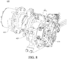
- the electric assembly 600 is mounted on the bogie frame 100, and the electric assembly 600 comprises a traction motor 610, a gear reducer 620 and a planetary wheel-side reducer 630.
- the traction motor 610 is connected with the input shaft of the gear reducer 620
- the output shaft of the gear reducer 620 is connected with the input end of the planetary wheel-side reducer 630
- the output end of the planetary wheel-side reducer 630 is connected with a hub of the walking wheel 300.
- the electric assembly 600 may be powered from the conductive rail 2001 on the rail girder 2000.
- the electric assembly 600 comprises at least two stages of reducing mechanisms, and the transmission ratio of the electric assembly 600 is large, thus the traction motor 610 with high rotating speed may be adopted in a certain range, the energy utilization ratio of the electric assembly 600 is high, and it is conducive to energy conservation and environmental protection.
- the bogie assembly 1000 adopts a driving solution of integrally mounting the traction motor 610, the gear reducer 620, the planetary wheel-side reducer 630, the hub and the like, the overall structure is simple, the occupied space is small, a low floor structure can be realized, the weight is light, the energy utilization ratio is high and it is conducive to energy conservation and environmental protection.
- the electric assembly 600 may be disposed on the inner side of the bogie frame 100, and the traction motor 610 may be transversely disposed, i.e., the axis of the motor shaft of the traction motor 610 may be oriented along the transverse direction (left-right direction).
- the traction motor 610 may be connected with the box body of the gear reducer 620, and the box body of the gear reducer 620 may be connected with the bogie frame 100.
- the bogie frame 100 may be provided with a motor mounting bracket, and the box body of the gear reducer 620 may be connected with the motor mounting bracket through threaded fastening members.
- the number of the motor mounting bracket may be two.
- the two motor mounting brackets are spaced apart along the front-rear direction to clamp the electric assembly 600.
- the motor mounting bracket may comprise a connecting plate and a supporting spoke plate, the connecting plate is connected with the box body of the gear reducer 620 through threads, the supporting spoke plate may be constructed to be triangular, and one side of the supporting spoke plate is welded with the connecting plate, and the other side is welded with the bogie frame 100.
- the electric assembly 600 may further comprise a brake 640, and the brake 640 may be disposed between the traction motor 610 and the walking wheel 300. As illustrated in Fig. 7 , the brake 640 is mounted between the gear reducer 620 and the hub of the walking wheel 300. In this way, no separate position for mounting the brake 640 on the bogie frame 100 is needed, the weight of the bogie assembly 1000 can be reduced, the space utilization ratio can be significantly improved, and a space is provided for the layout of other parts.
- the brake 640 comprises a brake disc 641, brake calipers 642 and a brake driving unit 643, wherein the brake disc 641 may be connected with the hub of the walking wheel 300, for example, the brake disc 641 may be connected with the hub of the walking wheel 300 through threaded connecting members, the brake calipers 642 may be connected with the box body of the gear reducer 620, and the brake driving unit 643 is used to drive the brake calipers 642.
- the brake driving unit 643 may be a cylinder.
- the brake 640 may also adopt a hydraulic brake driving unit 643 or a pneumatic-hydraulic brake driving unit 643.
- the embodiment of the present disclosure further discloses a bogie assembly 1000, and the bogie assembly 1000 according to the embodiment of the present disclosure comprises a bogie frame 100, a walking wheel 300 and the electric assembly 600 described in any one of the above-mentioned embodiments.
- the bogie assembly 1000 according to the embodiment of the present disclosure has the advantages that the overall structure is simple, the occupied space is small, the weight is light, the energy utilization ratio is high, and it is conducive to energy conservation and environmental protection.
- the embodiment of the present disclosure further discloses a straddle-type monorail vehicle, and the straddle-type monorail vehicle according to the embodiment of the present disclosure comprises the bogie assembly 1000 described in any one of the above-mentioned embodiments.
- the straddle-type monorail vehicle according to the embodiment of the present disclosure has the advantages that the structure is simple, the weight is light, the energy efficiency is high, and it is conducive to energy conservation and environmental protection.
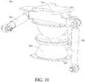
- the suspension system 700 according to the embodiment of the present disclosure will be described below with reference to Figs. 1 and 10 to 12 .
- the suspension system 700 is supported between the bogie frame 100 and the vehicle body.
- the suspension system 700 comprises an elastic member 740 and a shock absorber assembly
- the shock absorber assembly comprises a suspension mounting seat 710, a transverse shock absorber 720 and a longitudinal shock absorber 730.
- the suspension mounting seat 710 is adapted to be connected with the vehicle body
- the transverse shock absorber 720 is connected between the suspension mounting seat 710 and the bogie frame 100
- the longitudinal shock absorber 730 is connected between the suspension mounting seat 710 and the bogie frame 100
- the elastic member 740 is connected between the suspension mounting seat 710 and the bogie frame 100.
- the elastic member 740 is an hourglass spring, as illustrated in Figs. 1 and 11 .
- the elastic member 740, the transverse shock absorber 720 and the longitudinal shock absorber 730 may jointly ensure the stability of the straddle-type monorail vehicles in the upper-lower direction, the left-right direction, and the front-rear direction.
- the suspension system 700 can play the role of shock absorption and buffering, thus the shock or bump feeling of the rail vehicle in the course of running can be reduced and the running noise of the straddle-type monorail vehicle can be reduced.
- the suspension mounting seat 710 is located above the suspension supporting seat 120 of the bogie frame 100, the upper end of the elastic member 740 is connected to the suspension mounting seat 710, and the lower end of the elastic member 740 is connected to the suspension supporting seat 120.
- the transverse shock absorber 720 is hinged between the suspension mounting seat 710 and the frame body 110, and the longitudinal shock absorber 730 is hinged between the suspension mounting seat 710 and the suspension supporting seat 120.
- the hinging between the transverse shock absorber 720 and the frame body 110, the hinging between the transverse shock absorber 720 and the suspension mounting seat 710, the hinging between the longitudinal shock absorber 730 and the suspension mounting seat 710, and the hinging between the longitudinal shock absorber 730 and the suspension supporting seat 120 are spherical hinging, which can improve the shock absorbing effect of the suspension system 700 and avoid stress concentration, thus improving the reliability of the suspension system 700.
- the transverse shock absorber 720 and the longitudinal shock absorber 730 may be respectively located on the two sides of the elastic member 740.
- the number of the suspension systems 700 is even, such as two or four, and the suspension systems 700 are symmetrically disposed with respect to the center of the bogie frame 100, such that the vehicle body can be prevented from twisting in the horizontal plane and the stability of the rail vehicle in the running process can be improved.
- the elastic member 740 is an hourglass spring and is connected with the suspension supporting seat 120 of the bogie frame 100.
- the bogie assembly 1000 further comprises supporting plates 762, the supporting plates 762 are mounted on the suspension supporting seat 120, and the elastic members 740 are mounted on the supporting plates 762.
- the elastic member 740 may be connected with the supporting plate 762 through threaded fastening members.
- the supporting plate 762 may extend along the front-rear direction, two elastic members 740 are mounted on each supporting plate 762.
- the bogie frame 100 is provided with two suspension supporting seats 120 spaced apart along the left-right direction, and each suspension supporting seat 120 is connected with the supporting plate 762.
- each bogie frame 100 may have four elastic members 740, the four elastic members 740 are respectively distributed on the two sides of the frame body 110 of the bogie frame 100, i.e., two elastic members 740 are distributed on one side of the frame body 110 of the bogie frame 100, and the other two elastic members 740 are distributed on the other side of the frame body 110 of the bogie frame 100.
- four suspension systems 700 are provided, and the four suspension systems 700 are symmetrically distributed on the two sides of the frame body 110 of the bogie frame 100 with respect to the center of the bogie frame 100.
- suspension mounting seat 710 is not illustrated in the embodiments of Figs. 1 and 11 in order to illustrate the connection and position relationship between the elastic members 740 and other components.
- the elastic members 740 are air springs (i.e., the hourglass spring is replaced with the air spring, which is not shown in this embodiment), while the other components of the suspension system 700 remain unchanged, the bogie assembly 1000 according to the embodiments of the disclosure comprises a bogie frame 100, a traction mechanism 200 and a suspension system 700 with an air spring.
- the traction mechanism 200 is the traction mechanism 200 described in any one of the above-mentioned embodiments, the traction mechanism 200 comprises the traction frame 210, the traction frame 210 is arch-shaped, the traction frame 210 straddles the bogie frame 100 along the front-rear direction, and the traction frame 210 is adapted to be connected with the vehicle body.
- the suspension system 700 is mounted on the bogie frame 100, and the suspension system 700 is used to support the vehicle body.
- the support height of the air spring is adjustable, it is convenient to adjust the relative position of the vehicle body and the bogie frame 100, such that the application scope of the bogie assembly 1000 according to the embodiments of the present disclosure is wider.
- the suspension system 700 with the air spring is fit with the traction mechanism 200 with the above-mentioned structure, such that the bogie assembly 1000 works more stably and reliably.
- the suspension system 700 comprises an air spring 761
- the bogie assembly 1000 according to the embodiments of the present disclosure comprises a bogie frame 100, a traction mechanism 200 and a plurality of air springs 761.
- the traction mechanism 200 is the traction mechanism 200 described in any one of the above-mentioned embodiments, the traction mechanism 200 comprises the traction frame 210, the traction frame is arch-shaped, the traction frame 210 straddles the bogie frame 100 in the front-rear direction, and the traction frame 210 is adapted to be connected with the vehicle body.
- a plurality of air springs 761 is directly mounted on the frame body 110 of the bogie frame 100 to support the vehicle body, the number of the air springs 761 may be four, and the four air springs 761 are respectively distributed at four corners of the frame body 110, i.e., one air spring 761 is arranged at each corner of the frame body 110, and the centers of the four air springs 761 form four vertices of a rectangle. Therefore, the suspension system 700 uniformly supports the vehicle body and the vehicle body can be prevented from nodding.
- the embodiment of the present disclosure further discloses a straddle-type monorail vehicle, and the straddle-type monorail vehicle comprises the bogie assembly 1000 described in any one of the above-mentioned embodiments.
- the straddle-type monorail vehicle according to the embodiment of the present disclosure has good shock-proof performance.
- first and second are used only for description purposes, and shall not be understood as indicating or suggesting relative importance or implicitly indicating a quantity of indicated technical features. Therefore, features defined by “first” and “second” may explicitly or implicitly include at least one feature. In the description of the present disclosure, unless otherwise specifically limited, “multiple” means at least two, for example, two or three.
- connection may be a fixed connection, a detachable connection, or an integral connection; may be a mechanical connection or an electrical connection; may be a direct connection or an indirect connection by means of an intermediate medium; or may be internal communication between two elements or interaction relationship between two elements, unless otherwise clearly limited.
- a person of ordinary skill in the art may understand specific meanings of the foregoing terms in the present disclosure according to a specific situation.
Landscapes
- Engineering & Computer Science (AREA)
- Mechanical Engineering (AREA)
- Transportation (AREA)
- Chemical & Material Sciences (AREA)
- Combustion & Propulsion (AREA)
- Vibration Prevention Devices (AREA)
- Body Structure For Vehicles (AREA)
- Carriers, Traveling Bodies, And Overhead Traveling Cranes (AREA)
Abstract
The present disclosure provides a bogie assembly and a straddle-type monorail vehicle with the same. The bogie assembly comprises: a bogie frame; an electric assembly which is mounted on the bogie frame and comprises a traction motor, a gear reducer and a planetary wheel-side reducer, wherein the traction motor is connected with an input shaft of the gear reducer, and an output shaft of the gear reducer is connected with an input end of the planetary wheel-side reducer; and a walking wheel which is mounted on the bogie frame, wherein an output end of the planetary wheel-side reducer is connected with a hub of the walking wheel.
Description
- The present disclosure belongs to the field of vehicle manufacturing technology, and in particular relates to a bogie assembly and a straddle-type monorail vehicle with the bogie assembly.
- The laying cost of a straddle-type monorail transportation system is much lower than that of a subway transportation system, and its application scope is wider. An electric assembly is an important part of a straddle-type monorail vehicle. The reduction ratio of the electric assembly in the related technology is small, such that the electric assembly can only use a motor with low rotating speed, and the energy utilization efficiency of the motor with low rotating speed is relatively low. Moreover, the electric assembly in the related technology occupies a large space and cannot realize a low floor structure. The mass of the whole vehicle is larger, the energy consumption is higher, it is not conducive to energy conservation and environmental protection, and there is a space for improvement.
- The present disclosure aims at resolving one of technical problems in related technologies at least to some extent. For this reason, one purpose of the present disclosure is to provide a bogie assembly with a compact structure and high energy efficiency.
- Another purpose of the present disclosure is to provide a straddle-type monorail vehicle with the bogie assembly.
- The bogie assembly according to the embodiment in the first aspect of the present disclosure comprises: a bogie frame; an electric assembly, the electric assembly being mounted on the bogie frame, the electric assembly comprising a traction motor, a gear reducer and a planetary wheel-side reducer, the traction motor being connected with an input shaft of the gear reducer, and an output shaft of the gear reducer being connected with an input end of the planetary wheel-side reducer; and a walking wheel, the walking wheel being mounted on the bogie frame and an output end of the planetary wheel-side reducer being connected with a hub of the walking wheel.
- Since the bogie assembly according to the embodiment in the first aspect of the present disclosure adopts a driving solution of integrally mounting the traction motor, the gear reducer, the planetary wheel-side reducer, the hub and the like, the overall structure is simple, the occupied space is small, a low floor structure can be realized, the weight is light, the energy utilization ratio is high and it is conducive to energy conservation and environmental protection.
- In addition, the bogie assembly according to the embodiment of the present disclosure may further have the following additional technical features:
In some embodiments of the present disclosure, the electric assembly further comprises: a brake, the brake being disposed between the traction motor and the walking wheel. - In some embodiments of the present disclosure, the brake is mounted between the gear reducer and the hub of the walking wheel.
- In some embodiments of the present disclosure, the brake comprises: a brake disc, the brake disc being connected with the hub of the walking wheel; brake calipers, the brake calipers being connected with a box body of the gear reducer; and a brake driving unit, the brake driving unit being used for driving the brake calipers.
- In some embodiments of the present disclosure, the electric assembly is disposed on the inner side of the bogie frame.
- In some embodiments of the present disclosure, the traction motor is transversely disposed.
- In some embodiments of the present disclosure, the traction motor is connected with the box body of the gear reducer and the box body of the gear reducer is connected with the bogie frame.
- In some embodiments of the present disclosure, the bogie frame further comprises a traction mechanism comprising: a traction frame, the traction frame straddling the bogie frame along a front-rear direction; and a traction pin assembly, the traction pin assembly being connected with the traction frame and adapted to be connected with a vehicle body.
- In some embodiments of the present disclosure, the traction pin assembly comprises: a pin shaft, the pin shaft being connected with the top wall of the traction frame, the upper end of the pin shaft being provided with a flange and the flange being adapted to be connected with the vehicle body.
- In some embodiments of the present disclosure, the top wall of the traction frame is provided with a mounting hole, the pin shaft has a threaded segment, the pin shaft penetrates through the mounting hole and the threaded segment is fixed through a nut.
- In some embodiments of the present disclosure, the traction pin assembly further comprises: a bushing, the bushing being sleeved over the pin shaft; an upper shock absorbing pad, the upper shock absorbing pad being clamped between the flange and the upper surface of the top wall of the traction frame; and a lower shock absorbing pad, the lower shock absorbing pad being clamped between the nut and the lower surface of the top wall of the traction frame.
- In some embodiments of the present disclosure, the bushing comprises an outer steel bushing, an inner steel bushing and a buffer bushing between the outer steel bushing and the inner steel bushing.
- In some embodiments of the present disclosure, the traction pin assembly comprises: a pin shaft, the pin shaft being connected with the top wall of the traction frame; and a vehicle body connecting member, the vehicle body connecting member being arranged such that the rigidity in a front-rear direction is greater than the rigidity in the left-right direction, and comprising: a pin bushing mounting seat, the pin bushing mounting seat being adapted to be connected with the vehicle body; and a pin bushing, the pin bushing being connected with the pin bushing mounting seat and sleeved over the pin shaft.
- In some embodiments of the present disclosure, the pin bushing mounting seat comprises: a fixing cylinder, the fixing cylinder being sleeved over the pin bushing and a buffer member being arranged between the fixing cylinder and the pin bushing; and a mounting plate, the mounting plate being connected with the fixing cylinder and adapted to be connected with the vehicle body.
- In some embodiments of the present disclosure, the fixing cylinder and the buffer member respectively have an elliptical horizontal section, moreover the long axis of the elliptical horizontal section is oriented along the front-rear direction, and the short axis of the elliptical horizontal section is oriented along the left-right direction.
- In some embodiments of the present disclosure, a gap is provided in the buffer member and the gap is located on the left side or the right side of the pin shaft.
- In some embodiments of the present disclosure, the number of the gaps is two and the two gaps are respectively located on the left side and the right side of the pin shaft.
- In some embodiments of the present disclosure, the horizontal section of the gap is arch-shaped and comprises a first segment, a second segment and a third segment sequentially connected along the front-rear direction, the second segment is rectangular, the long side of the second segment faces the pin bushing, the first segment is an arc-shaped segment extending from the short side of the second segment to the edge of the buffer member, and the first segment and the third segment are symmetrically arranged.
- In some embodiments of the present disclosure, the buffer member comprises a plurality of sub-buffer members.
- In some embodiments of the present disclosure, the buffer member is partitioned into four sub-buffer members by two parallel partitioning planes and the pin bushing, the normal of each partitioning plane is oriented along the front-rear direction, and each partitioning plane is intersected with the pin bushing.
- In some embodiments of the present disclosure, a gap is provided in the buffer member, the gap divides the sub-buffer member between the two partitioning planes into two portions, the portion, close to the pin bushing, in the two portions is fixedly connected with the pin bushing, and the portion, close to the fixing cylinder, in the two portions is fixedly connected with the fixing cylinder.
- In some embodiments of the present disclosure, the traction frame is arch-shaped and covers a position above the walking wheel.
- In some embodiments of the present disclosure, the traction frame comprises: a top wall; and two sidewalls, the upper ends of the two sidewalls being respectively connected with the front end and the rear end of the top wall, the lower end of each sidewall being provided with a plurality of fixing seats used for being connected with the bogie frame such that the traction frame is adapted to straddle the bogie frame along the front-rear direction, the plurality of fixing seats at the lower end of the same sidewall comprising a first fixing seat and a second fixing seat, and the bottom surface of the first fixing seat and the bottom surface of the second fixing seat being located on different horizontal planes.
- In some embodiments of the present disclosure, the position between the first fixing seat and the corresponding second fixing seat is hollowed out to form a lightening hole.
- In some embodiments of the present disclosure, the width of the sidewalls is gradually increased from top to bottom.
- In some embodiments of the present disclosure, the top wall is flat and the sidewalls are arc-shaped.
- In some embodiments of the present disclosure, the sidewall comprises a plurality of sequentially connected arc-shaped segments.
- In some embodiments of the present disclosure, the bogie assembly further comprises a suspension system comprising: a suspension mounting seat, the suspension mounting seat being adapted to be connected with the vehicle body; a transverse shock absorber, the transverse shock absorber being connected between the suspension mounting seat and the bogie frame; a longitudinal shock absorber, the longitudinal shock absorber being connected between the suspension mounting seat and the bogie frame; and an elastic member, the elastic member being connected between the suspension mounting seat and the bogie frame.
- The straddle-type monorail vehicle according to the embodiment of the second aspect of the present disclosure comprises the bogie assembly according to the embodiment of the first aspect of the present disclosure.
- The straddle-type monorail vehicle according to the embodiment of the present disclosure has the same advantages as the bogie assembly according to the embodiment of the present disclosure relative to the prior art, which will not be repetitively described here.
- The foregoing and/or additional aspects and advantages of the present disclosure become obvious and easily understood in descriptions of the embodiments with reference to the following accompanying drawings.
-
Fig. 1 is a structural schematic diagram of a bogie assembly and a rail girder according to one embodiment of the present disclosure; -
Fig. 2 is a structural schematic diagram of a bogie assembly and a traction mechanism according to one embodiment of the present disclosure; -
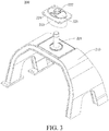
Fig. 3 is a structural schematic diagram of a traction mechanism according to one embodiment of the present disclosure; -
Fig. 4 is a top view of a traction pin assembly according to one embodiment of the present disclosure; -
Fig. 5 is a structural schematic diagram of a traction mechanism according to another embodiment of the present disclosure; -
Fig. 6 is a sectional view of a traction pin assembly according to another embodiment of the present disclosure; -
Fig. 7 is a structural schematic diagram of an electric assembly according to one embodiment of the present disclosure; -
Fig. 8 is a structural schematic diagram of an electric assembly (without a brake) according to one embodiment of the present disclosure; -
Fig. 9 is a structural schematic diagram of a brake according to one embodiment of the present disclosure; -
Fig. 10 is a structural schematic diagram of a suspension system according to one embodiment of the present disclosure; -
Fig. 11 is a structural schematic diagram of a bogie assembly according to one embodiment of the present disclosure; and -
Fig. 12 is a structural schematic diagram of a bogie assembly and a rail girder according to another embodiment of the present disclosure. -
-
bogie assembly 1000, -
bogie frame 100,frame body 110,suspension supporting seat 120, -
traction mechanism 200, -
traction frame 210,top wall 211,sidewall 212, reinforcingrib 212a,first fixing seat 213, first connectingarm 213a,first mounting plate 213b,second fixing seat 214, second connectingarm 214a,second mounting plate 214b,lightening hole 215, -
traction pin assembly 220,pin shaft 221,flange 221a, threadedsegment 221b,pin bushing 222,fixing cylinder 223,mounting plate 224,buffer member 225,sub-buffer member partitioning plane 225e,gap 226,first segment 226a,second segment 226b,third segment 226c,bushing 227, uppershock absorbing pad 228a, lowershock absorbing pad 228b,nut 229a,gasket 229b, -
walking wheel 300,guide wheel 400, stabilizingwheel 500, -
electric assembly 600,traction motor 610,gear reducer 620, planetary wheel-side reducer 630,brake 640,brake disc 641,brake calipers 642,brake driving unit 643, -
suspension system 700,suspension mounting seat 710,transverse shock absorber 720,longitudinal shock absorber 730,elastic member 740,air spring 761, supportingplate 762, -
rail girder 2000,conductor rail 2001. - The following describes in detail embodiments of the present disclosure. Examples of the embodiments are shown in the accompanying drawings, where reference signs that are the same or similar from beginning to end represent same or similar components or components that have same or similar functions. The embodiments described below with reference to the accompanying drawings are exemplary, and are used for explaining rather than limiting the present disclosure.
- In the descriptions of this specification, descriptions such as reference terms "an embodiment", "some embodiments", "example", "specific example", or "some examples" intend to indicate that specific features, structures, materials, or characteristics described with reference to embodiments or examples are included in at least one embodiment or example of the present disclosure. In this specification, schematic descriptions of the foregoing terms do not need to aim at a same embodiment or example. Besides, the specific features, the structures, the materials or the characteristics that are described may be combined in a proper manner in any one or more embodiments or examples. In addition, in a case that is not mutually contradictory, persons skilled in the art can combine or group different embodiments or examples that are described in this specification and features of the different embodiments or examples.
- In the description of the present disclosure, it needs to be understood that "front-rear direction" and "longitudinal" are the running directions of the straddle-type monorail vehicle, i.e., the extending direction of the
rail girder 2000, "left-right direction" is perpendicular to the running direction of the straddle-type monorail vehicle, "left-right direction" is the "transverse direction" of the straddle-type monorail vehicle, and "upper-lower direction" is the upper-lower direction in the conventional concept, "inside" refers to a position close to therail girder 2000, and "outside" refers to a position far away from therail girder 2000. - The present disclosure is described in detail below with reference to the accompanying drawings and the embodiments.
- A
bogie assembly 1000 according to one embodiment of the present disclosure will be described in detail with reference to the drawings. As illustrated inFigs. 1 to 12 , thebogie assembly 1000 comprises abogie frame 100, atraction mechanism 200, awalking wheel 300, guidewheels 400, stabilizingwheels 500, anelectric assembly 600 and asuspension system 700. - The
bogie frame 100 is provided with a rail concave portion for straddling therail girder 2000. Thetraction mechanism 200, thewalking wheel 300, theguide wheels 400, the stabilizingwheels 500, theelectric assembly 600 and thesuspension system 700 are all mounted on thebogie frame 100. Thesuspension system 700 is supported between thebogie frame 100 and the vehicle body of the straddle-type monorail vehicle. Theelectric assembly 600 is used to drive thewalking wheel 300 to move along the walking surface of therail girder 2000. Thetraction mechanism 200 is connected between thebogie frame 100 and the vehicle body of the straddle-type monorail vehicle. Thetraction mechanism 200 is used to transfer the power of thewalking wheel 300 to the vehicle body. Theguide wheels 400 and the stabilizingwheels 500 clamp the sidewalls of therail girder 2000. - The
walking wheel 300, theguide wheels 400 and the stabilizingwheels 500 according to the embodiment of the present disclosure will be described below with reference to the drawings. - As illustrated in
Fig. 1 andFig. 12 , thewalking wheel 300 runs along the walking surface (upper surface) of therail girder 2000. The number of thewalking wheel 300 is at least one, and the rotating axis of thewalking wheel 300 is in parallel with the walking surface of therail girder 2000. In some embodiments of the present disclosure, thewalking wheel 300 may comprise a rubber tire, such that the shock-proof performance of the straddle-type monorail vehicle is better. Of course, thewalking wheel 300 may also be a steel wheel. - As illustrated in
Fig. 1 ,Fig. 11 andFig. 12 , thebogie assembly 1000 may be provided with two pairs ofguide wheels 400, the two pairs ofguide wheels 400 are spaced apart along the front-rear direction, each pair ofguide wheels 400 comprises twoguide wheels 400, the twoguide wheels 400 are symmetrically arranged with respect to therail girder 2000, and the twoguide wheels 400 are respectively in contact with one sidewall of therail girder 2000. The distance between the rotating axes of the twoguide wheels 400 in the same pair ofguide wheels 400 and the rotating axis of thewalking wheel 300 is equal. - The number of the stabilizing
wheels 500 is at least two. The two stabilizingwheels 500 are symmetrically arranged with respect to therail girder 2000. The two stabilizingwheels 500 are respectively in contact with one sidewall of therail girder 2000, and the rotating axis of each stabilizingwheel 500 is perpendicular to the rotating axis of thewalking wheel 300. - The
traction mechanism 200 according to the embodiment of the present disclosure will described below with reference toFigs. 2 to 6 . As illustrated inFigs. 2 to 6 , thetraction mechanism 200 comprises atraction frame 210 and atraction pin assembly 220, thetraction frame 210 is connected with theframe body 110 of thebogie frame 100, thetraction pin assembly 220 is connected with thetraction frame 210, and thetraction pin assembly 220 is adapted to be connected with the vehicle body. The traction force is transmitted successively through thebogie frame 100, thetraction frame 210, thetraction pin assembly 220 and the vehicle body. - The
traction frame 210 according to the embodiment of the present disclosure will be described firstly with reference toFig. 2 . As illustrated inFig. 2 , thetraction frame 210 comprises atop wall 211,sidewalls 212 and fixing seats. - Herein, two
sidewalls 212 are provided. The upper ends of the twosidewalls 212 are respectively connected with the front end of thetop wall 211 and the rear end of thetop wall 211. The lower end of eachsidewall 212 is provided with a plurality of fixing seats, the fixing seats are used for being connected with theframe body 110. The plurality of fixing seats connected below the twosidewalls 212 is respectively connected with the front arm and rear arm of theframe body 110, that is, the plurality of fixing seats below onesidewall 212 is connected with the front arm of theframe body 110, and plurality of fixing seats below theother sidewall 212 is connected with the rear arm of theframe body 110, such that thetraction frame 210 is adapted to straddling thebogie frame 100 along the front-rear direction. Thus, the rigidity of thetraction frame 210 in the front-rear direction is greater than that in the left-right direction, and it helps thetraction frame 210 to transfer the traction force in the front-rear direction. - Referring to
Fig. 2 , the plurality of fixing seats at the lower end of thesame sidewall 212 comprises a first fixingseat 213 and a second fixingseat 214, the first fixingseat 213 and the second fixingseat 214 are disposed at an interval along the left-right direction, the heights of the left half segment and right half segment of each of the front arm and rear arm of theframe body 110 are different, and the left half segment and the right half segment are connected by an arc-shaped segment, such that the strength of thebogie frame 100 is higher. In addition, the bottom surface of the first fixingseat 213 and the bottom surface of the second fixingseat 214 are located on different horizontal planes to fit with theframe body 110 of thebogie frame 100. As a result, the mounting strength of thetraction frame 210 is high, and the fitting with thebogie frame 100 is better and it helps to realize better transfer of the traction force. - In the the
traction frame 210 according to the embodiment of the present disclosure, by providing a plurality of fixing seats at different heights, it helps thetraction frame 210 to fit with thebogie frame 100, the strength of thetraction frame 210 is high, it can bear larger traction force, and the traction process is stable and reliable. - The
sidewalls 212 and thetop wall 211 of thetraction frame 210 may be jointly formed as an arch-shaped structure, thetraction frame 210 is adapted to cover a position above thewalking wheel 300, thetop wall 211 may be flat, thetop wall 211 is adapted to be connected with the vehicle body, and thesidewalls 212 may be arc-shaped. In the embodiment illustrated inFig. 2 , thesidewall 212 comprises a plurality of sequentially connected arc-shaped segments, and the width of thesidewall 212 is gradually increased from top to bottom, such that the strength of thetraction frame 210 is higher and the traction stability is higher. - The edges of the left and right sides of the
sidewall 212 may be provided with reinforcingribs 212a to enhance the strength of thesidewall 212. By taking the right side of thesidewall 212 as an example, the front edge and the rear edge of the right side of thesidewall 212 respectively extend transversely outwards (i.e., towards the right) to form the reinforcingribs 212a, and the formation method of the reinforcingribs 212a of the edges of the left side of thesidewall 212 is the same as that of the right side. - Referring to
Fig. 2 , a position between the first fixingseat 213 and the corresponding second fixingseat 214 may be hollowed out to form alightening hole 215. Thus, on the premise that the transfer of the traction force is not affected, the weight of thetraction frame 210 can be reduced, and the lightweight level of thetraction frame 210 can be improved. There may be an arc-shaped transition angle between the sidewall of the lighteninghole 215 and the top wall of the lighteninghole 215 to prevent stress concentration from being caused at the junction between the sidewall of the lighteninghole 215 and the top wall of the lighteninghole 215, such that the durability of thetraction frame 210 is higher. - The first fixing
seat 213 may comprise a first connectingarm 213a and afirst mounting plate 213b, the first connectingarm 213a is connected with thecorresponding sidewall 212, and the first mountingplate 213b is connected with the first connectingarm 213a. Referring toFig. 2 , the upper end of the first connectingarm 213a is connected with thecorresponding sidewall 212, and the lower end of the first connectingarm 213a is connected with the corresponding first mountingplate 213b. In some embodiments of the present disclosure, the first connectingarm 213a can be connected with the first mountingplate 213b through welding. In addition, the first mountingplate 213b is adapted to be connected with thebogie frame 100. For example, the first mountingplate 213b may be provided with a plurality of mounting holes, and threaded fastening members penetrate through the mounting holes and are connected with theframe body 110 of thebogie frame 100, so as to connect the first mountingplate 213b to thebogie frame 100. - The
second fixing seat 214 may comprise a second connectingarm 214a and asecond mounting plate 214b, the second connectingarm 214a is connected with thecorresponding sidewall 212, and thesecond mounting plate 214b is connected with the second connectingarm 214a. Referring toFig. 2 , the upper end of the second connectingarm 214a is connected with thecorresponding sidewall 212, and the lower end of the second connectingarm 214a is connected with the corresponding second mountingplate 214b. In some embodiments of the present disclosure, the second connectingarm 214a may be connected with thesecond mounting plate 214b through welding. In addition, thesecond mounting plate 214b is adapted to be connected with thebogie frame 100. For example, thesecond mounting plate 214b may be provided with a plurality of mounting holes, and threaded fastening members penetrate through the mounting holes and are connected with theframe body 110 of thebogie frame 100, so as to connect thesecond mounting plate 214b to thebogie frame 100. - In some embodiments of the present disclosure, the first connecting
arm 213a and the second connectingarm 214a are respectively and integrally molded with thecorresponding sidewalls 212, that is, the first connectingarm 213a is integrally molded with thecorresponding sidewall 212, and the second connectingarm 214a is also integrally molded with thecorresponding sidewall 212. In addition, the reinforcingrib 212a may extend from the edge of thesidewall 212 to the edge of the outer side of the first connectingarm 213a (i.e. the edge of the left side), the edge of the outer side of the second connectingarm 214a (i.e. the edge of the right side) and the edge of the lower side of thetop wall 211. - The embodiment of the present disclosure further discloses a
bogie assembly 1000. Thebogie assembly 1000 according to the embodiment of the present disclosure is provided with thetraction frame 210 described in any one of the above-mentioned embodiments, and thetraction frame 210 is connected with thebogie frame 100. The traction force of thebogie assembly 1000 according to the embodiment of the present disclosure is transferred stably, and it can bear a larger driving force. - The embodiment of the present disclosure further discloses a straddle-type monorail vehicle. The straddle-type monorail vehicle according to the embodiment of the present disclosure is provided with the
bogie assembly 1000 described in any one of the above-mentioned embodiments, and thetraction frame 210 of thebogie assembly 1000 is connected with the vehicle body of the straddle-type monorail vehicle. The straddle-type monorail vehicle according to the embodiment of the present disclosure can transfer traction force stably. - The
traction pin assembly 220 according to the embodiment of the present disclosure will be described below with reference toFigs. 2 to 6 . - As illustrated in
Figs. 2 to 4 , in some embodiments of the present disclosure, thetraction pin assembly 220 comprises apin shaft 221 and a vehicle body connecting member, thepin shaft 221 is connected with thetraction frame 210 and the vehicle body connecting member, the vehicle body connecting member is adapted to be connected with the vehicle body, and the vehicle body connecting member is configured such that the rigidity in the front-rear direction is greater than the rigidity in the left-right direction. - It can be understood that, in the working process of the
traction mechanism 200, the traction force is mainly transferred along the front-rear direction, and the traction force is transferred from thetraction frame 210 to the vehicle body through thepin shaft 221 and the vehicle body connecting member. By configuring the vehicle body connecting member such that the rigidity in the front-rear direction is greater than the rigidity in the left-right direction, the vehicle body connecting member can be prevented from being damaged, the traction is more stable and the stress concentration can be avoided during steering. - Referring to
Figs. 3 and4 , the vehicle body connecting member may comprise a pin bushing mounting seat and apin bushing 222. Thepin bushing 222 is connected with the pin bushing mounting seat, and the pin bushing mounting seat is adapted to be connected with the vehicle body. The pin bushing mounting seat may comprise a fixingcylinder 223 and a mountingplate 224, the mountingplate 224 is connected with the fixingcylinder 223, the fixingcylinder 223 may be sleeved over thepin bushing 222, and abuffer member 225 is arranged between the fixingcylinder 223 and thepin bushing 222. One end of thepin shaft 221 is fixedly connected onto thetop wall 211 of thetraction frame 210. For example, thepin shaft 221 may be connected with thetop wall 211 of thetraction frame 210 through welding, and thepin bushing 222 is sleeved over thepin shaft 221, and thepin bushing 222 may be in interference fit with thepin shaft 221, such that thepin bushing 222 and thepin shaft 221 are not easily worn and do not produce abnormal noise. - The mounting
plate 224 is adapted to be connected with the vehicle body. For example, the mountingplate 224 may be connected with the vehicle body through threaded fastening members. The mountingplate 224 may surround the fixingcylinder 223 along the circumferential wall of the fixingcylinder 223, that is, the fixingcylinder 223 may penetrate through the mountingplate 224, and the height of the portion, above the mountingplate 224, of the fixingcylinder 223 is smaller than that below the mountingplate 224. When the vehicle body connecting member is connected with the vehicle body, the portion, above the mountingplate 224, of the fixingcylinder 223 may be fit with the concave portion on the vehicle body to realize the positioning between the mountingplate 224 and the vehicle body. - When the
traction mechanism 200 works, the traction force is sequentially transmitted between thetraction frame 210, thepin shaft 221, thepin bushing 222, thebuffer member 225, the fixingcylinder 223 and the mountingplate 224, and then is transferred to the vehicle body to achieve traction of the vehicle body. The noise during traction force transfer is low, the traction is stable, and it can bear a larger traction force. - In the embodiment illustrated in
Fig. 4 , the fixingcylinder 223 may have an elliptical horizontal section, and the long axis of the elliptical horizontal section is oriented along the front-rear direction, the short axis of the elliptical horizontal section is oriented along the left-right direction, thebuffer member 225 has an elliptical horizontal section, and the long axis of the elliptical horizontal section is oriented along the front-rear direction, and the short axis of the elliptical horizontal section is oriented along the left-right direction. In this way, the rigidity of the vehicle body connecting member in the front-rear direction can be enabled to be greater than that in the left-right direction, moreover thebuffer member 225 can absorb more shock in the front-rear direction, and thus the shock-proof performance of thetraction mechanism 200 is better. - In some embodiments of the present disclosure, a
gap 226 is provided in thebuffer member 225, thegap 226 may be located on the left side or right side of thepin bushing 222. As illustrated inFig. 4 , the number of thegaps 226 may be two, the twogaps 226 may be respectively located on the left side and right side of thepin bushing 222, the twogaps 226 may be symmetrically arranged with respect to a symmetry plane, the normal of the symmetry plane is oriented along the left-right direction, and the central axis of thepin bushing 222 is in the symmetry plane. - It can be understood that, in the working process of the
traction mechanism 200, the traction force is mainly transferred along the front-rear direction, and the shock impact is mainly from the front-rear direction. By configuring thegaps 226 on the left side and right side of thepin bushing 222, the mass of thetraction mechanism 200 can be reduced, the rigidity of the vehicle body connecting member in the left-right direction can be reduced, and the connection strength of the vehicle body connecting member in the left-right direction can be increased. - Referring to
Fig. 4 , the horizontal section of thegap 226 may be arch-shaped. Thegap 226 comprises afirst segment 226a, asecond segment 226b and athird segment 226c sequentially connected along the front-back direction. Thesecond segment 226b is rectangular, and the long side of the rectangularsecond segment 226b faces thepin bushing 222. Thefirst segment 226a is an arc-shaped segment extending from the short side of thesecond segment 226b to the edge of thebuffer member 225, and thefirst segment 226a and thethird segment 226c are symmetrically arranged. - In some embodiments of the present disclosure, the
buffer member 225 may include a plurality of sub-buffer members. As illustrated inFig. 4 , thebuffer member 225 is divided into foursub-buffer members parallel partitioning planes 225e and thepin bushing 222. The normal of thepartitioning planes 225e is oriented along the front-rear direction, and the twopartitioning planes 225e are intersected with thepin bushing 222. - The
sub-buffer member 225a and thesub-buffer member 225c are symmetrically arranged, thesub-buffer member 225b and thesub-buffer member 225d are symmetrically arranged, and thesub-buffer member 225b and thesub-buffer member 225d are located between the twopartitioning planes 225e. - The two
gaps 226 respectively divide thesub-buffer member 225b and thesub-buffer member 225d into two portions, the portion, close to thepin bushing 222, in the two portions is fixedly connected with thepin bushing 222, and the portion, close to the fixingcylinder 223, in the two portions is fixedly connected with the fixingcylinder 223. For example, thebuffer member 225 may be a rubber member, thepin bushing 222 and the fixingcylinder 223 may be metal members, and thebuffer member 225 may be respectively vulcanized with thepin bushing 222 and the fixingcylinder 223. Thus, the two portions of thesub-buffer member 225b and thesub-buffer member 225d divided by thegaps 226 can be prevented from shaking along the left-right direction. - As illustrated in
Figs. 5 to 6 , in other embodiments of the present disclosure, thetraction pin assembly 220 may comprise apin shaft 221, and thepin shaft 221 is connected to thetop wall 211 of thetraction frame 210. For example, thetop wall 211 of thetraction frame 210 may be provided with a mounting hole, the lower end of thepin shaft 221 may have a threadedsegment 221b, thepin shaft 221 penetrates through the mounting hole, and the threadedsegment 221b is fixed through anut 229a. Thenut 229a may be located below thetop wall 211 of thetraction frame 210, and agasket 229b may be clamped between thenut 229a and thetop wall 211 of thetraction frame 210. The upper end of thepin shaft 221 may be provided with aflange 221a, and theflange 221a is adapted to be connected with the vehicle body through threaded fastening members. - In some embodiments of the present disclosure, the
traction pin assembly 220 may further comprise an uppershock absorbing pad 228a and a lowershock absorbing pad 228b, the uppershock absorbing pad 228a may be clamped between theflange 221a and the upper surface of thetop wall 211 of thetraction frame 210, and the lowershock absorbing pad 228b may be clamped between thenut 229a and the lower surface of thetop wall 211. Specifically, the lowershock absorbing pad 228b may be clamped between the lower surface of thetop wall 211 and thegasket 229b. In some embodiments of the present disclosure, both the uppershock absorbing pad 228a and the lowershock absorbing pad 228b may be rubber members. - The
traction pin assembly 220 may further comprise abushing 227, thebushing 227 is sleeved over thepin shaft 221, and the length of thebushing 227 may be the same as the thickness of thetop wall 211 of thetraction frame 210. Thebushing 227 may comprise a plurality of layers, such as an outer steel bushing, an inner steel bushing and a buffer bushing. The buffer bushing is located between the outer steel bushing and the inner steel bushing, and the buffer bushing may be a rubber member. The outer steel bushing may be in interference fit with the mounting hole in thetop wall 211 of thetraction frame 210, the inner steel bushing is sleeved over thepin shaft 221, and the inner steel bushing may be in interference fit with thepin shaft 221. - The
traction mechanism 200 according to the embodiment of the present disclosure comprises thetraction frame 210 according to any one of the above-mentioned embodiments and thetraction pin assembly 220 according to any one of the above-mentioned embodiments, such that the strength of thetraction mechanism 200 is high, it can bear a larger traction force, the traction process is stable and reliable, and the noise is low. - The embodiment of the present disclosure further discloses a
bogie assembly 1000. Thebogie assembly 1000 according to the embodiment of the present disclosure is provided with thetraction mechanism 200 described in any one of the above-mentioned embodiments, and thetraction mechanism 200 is connected with thebogie frame 100 of thebogie assembly 1000. The traction force of thebogie assembly 1000 according to the embodiment of the present disclosure is transferred stably and it can bear a larger driving force. - The embodiment of the present disclosure further discloses a straddle-type monorail vehicle. The straddle-type monorail vehicle according to the embodiment of the disclosure is provided with a
bogie assembly 1000 described in any one of the above-mentioned embodiments, and thetraction mechanism 200 of thebogie assembly 1000 is connected with the vehicle body of the straddle-type monorail vehicle. The traction force of the straddle-type monorail vehicle according to the embodiment of the present disclosure is stably transferred. - The
electric assembly 600 according to the embodiment of the present disclosure will be described below with reference toFigs. 1 and7 to 9 . - Referring to
Figs. 1 and7 , theelectric assembly 600 is mounted on thebogie frame 100, and theelectric assembly 600 comprises atraction motor 610, agear reducer 620 and a planetary wheel-side reducer 630. Thetraction motor 610 is connected with the input shaft of thegear reducer 620, the output shaft of thegear reducer 620 is connected with the input end of the planetary wheel-side reducer 630, and the output end of the planetary wheel-side reducer 630 is connected with a hub of thewalking wheel 300. Theelectric assembly 600 may be powered from theconductive rail 2001 on therail girder 2000. - That is to say, the
electric assembly 600 comprises at least two stages of reducing mechanisms, and the transmission ratio of theelectric assembly 600 is large, thus thetraction motor 610 with high rotating speed may be adopted in a certain range, the energy utilization ratio of theelectric assembly 600 is high, and it is conducive to energy conservation and environmental protection. - Since the
bogie assembly 1000 according to the embodiment of the present disclosure adopts a driving solution of integrally mounting thetraction motor 610, thegear reducer 620, the planetary wheel-side reducer 630, the hub and the like, the overall structure is simple, the occupied space is small, a low floor structure can be realized, the weight is light, the energy utilization ratio is high and it is conducive to energy conservation and environmental protection. - In some embodiments of the present disclosure, the
electric assembly 600 may be disposed on the inner side of thebogie frame 100, and thetraction motor 610 may be transversely disposed, i.e., the axis of the motor shaft of thetraction motor 610 may be oriented along the transverse direction (left-right direction). In this way, the structure thebogie assembly 1000 is compact structure, and the transverse and longitudinal sizes are smaller. Thetraction motor 610 may be connected with the box body of thegear reducer 620, and the box body of thegear reducer 620 may be connected with thebogie frame 100. For example, thebogie frame 100 may be provided with a motor mounting bracket, and the box body of thegear reducer 620 may be connected with the motor mounting bracket through threaded fastening members. The number of the motor mounting bracket may be two. The two motor mounting brackets are spaced apart along the front-rear direction to clamp theelectric assembly 600. The motor mounting bracket may comprise a connecting plate and a supporting spoke plate, the connecting plate is connected with the box body of thegear reducer 620 through threads, the supporting spoke plate may be constructed to be triangular, and one side of the supporting spoke plate is welded with the connecting plate, and the other side is welded with thebogie frame 100. - In some embodiments of the present disclosure, the
electric assembly 600 may further comprise abrake 640, and thebrake 640 may be disposed between thetraction motor 610 and thewalking wheel 300. As illustrated inFig. 7 , thebrake 640 is mounted between thegear reducer 620 and the hub of thewalking wheel 300. In this way, no separate position for mounting thebrake 640 on thebogie frame 100 is needed, the weight of thebogie assembly 1000 can be reduced, the space utilization ratio can be significantly improved, and a space is provided for the layout of other parts. - Referring to
Fig. 9 , thebrake 640 comprises abrake disc 641,brake calipers 642 and abrake driving unit 643, wherein thebrake disc 641 may be connected with the hub of thewalking wheel 300, for example, thebrake disc 641 may be connected with the hub of thewalking wheel 300 through threaded connecting members, thebrake calipers 642 may be connected with the box body of thegear reducer 620, and thebrake driving unit 643 is used to drive thebrake calipers 642. In some embodiments of the present disclosure, thebrake driving unit 643 may be a cylinder. Of course, thebrake 640 may also adopt a hydraulicbrake driving unit 643 or a pneumatic-hydraulicbrake driving unit 643. - The embodiment of the present disclosure further discloses a
bogie assembly 1000, and thebogie assembly 1000 according to the embodiment of the present disclosure comprises abogie frame 100, awalking wheel 300 and theelectric assembly 600 described in any one of the above-mentioned embodiments. Thebogie assembly 1000 according to the embodiment of the present disclosure has the advantages that the overall structure is simple, the occupied space is small, the weight is light, the energy utilization ratio is high, and it is conducive to energy conservation and environmental protection. - The embodiment of the present disclosure further discloses a straddle-type monorail vehicle, and the straddle-type monorail vehicle according to the embodiment of the present disclosure comprises the
bogie assembly 1000 described in any one of the above-mentioned embodiments. The straddle-type monorail vehicle according to the embodiment of the present disclosure has the advantages that the structure is simple, the weight is light, the energy efficiency is high, and it is conducive to energy conservation and environmental protection. - The
suspension system 700 according to the embodiment of the present disclosure will be described below with reference toFigs. 1 and10 to 12 . - The
suspension system 700 is supported between thebogie frame 100 and the vehicle body. As illustrated inFig. 10 , thesuspension system 700 comprises anelastic member 740 and a shock absorber assembly, and the shock absorber assembly comprises asuspension mounting seat 710, atransverse shock absorber 720 and alongitudinal shock absorber 730. Thesuspension mounting seat 710 is adapted to be connected with the vehicle body, thetransverse shock absorber 720 is connected between thesuspension mounting seat 710 and thebogie frame 100, thelongitudinal shock absorber 730 is connected between thesuspension mounting seat 710 and thebogie frame 100, and theelastic member 740 is connected between thesuspension mounting seat 710 and thebogie frame 100. In some embodiments of the present disclosure, theelastic member 740 is an hourglass spring, as illustrated inFigs. 1 and11 . - Thus, the
elastic member 740, thetransverse shock absorber 720 and thelongitudinal shock absorber 730 may jointly ensure the stability of the straddle-type monorail vehicles in the upper-lower direction, the left-right direction, and the front-rear direction. Moreover, thesuspension system 700 can play the role of shock absorption and buffering, thus the shock or bump feeling of the rail vehicle in the course of running can be reduced and the running noise of the straddle-type monorail vehicle can be reduced. - In some embodiments of the present disclosure, the
suspension mounting seat 710 is located above thesuspension supporting seat 120 of thebogie frame 100, the upper end of theelastic member 740 is connected to thesuspension mounting seat 710, and the lower end of theelastic member 740 is connected to thesuspension supporting seat 120. Thetransverse shock absorber 720 is hinged between thesuspension mounting seat 710 and theframe body 110, and thelongitudinal shock absorber 730 is hinged between thesuspension mounting seat 710 and thesuspension supporting seat 120. - Herein, the hinging between the
transverse shock absorber 720 and theframe body 110, the hinging between thetransverse shock absorber 720 and thesuspension mounting seat 710, the hinging between thelongitudinal shock absorber 730 and thesuspension mounting seat 710, and the hinging between thelongitudinal shock absorber 730 and thesuspension supporting seat 120 are spherical hinging, which can improve the shock absorbing effect of thesuspension system 700 and avoid stress concentration, thus improving the reliability of thesuspension system 700. - Referring to
Fig. 10 , in order to enable thesuspension system 700 to be reasonably constructed and to enable thetransverse shock absorber 720 and thelongitudinal shock absorber 730 to work better, thetransverse shock absorber 720 and thelongitudinal shock absorber 730 may be respectively located on the two sides of theelastic member 740. - In some embodiments of the present disclosure, the number of the
suspension systems 700 is even, such as two or four, and thesuspension systems 700 are symmetrically disposed with respect to the center of thebogie frame 100, such that the vehicle body can be prevented from twisting in the horizontal plane and the stability of the rail vehicle in the running process can be improved. - In the embodiments illustrated in
Figs. 1 and11 , theelastic member 740 is an hourglass spring and is connected with thesuspension supporting seat 120 of thebogie frame 100. Specifically, thebogie assembly 1000 further comprises supportingplates 762, the supportingplates 762 are mounted on thesuspension supporting seat 120, and theelastic members 740 are mounted on the supportingplates 762. For example, theelastic member 740 may be connected with the supportingplate 762 through threaded fastening members. The supportingplate 762 may extend along the front-rear direction, twoelastic members 740 are mounted on each supportingplate 762. Thebogie frame 100 is provided with twosuspension supporting seats 120 spaced apart along the left-right direction, and eachsuspension supporting seat 120 is connected with the supportingplate 762. That is to say, eachbogie frame 100 may have fourelastic members 740, the fourelastic members 740 are respectively distributed on the two sides of theframe body 110 of thebogie frame 100, i.e., twoelastic members 740 are distributed on one side of theframe body 110 of thebogie frame 100, and the other twoelastic members 740 are distributed on the other side of theframe body 110 of thebogie frame 100. In other words, foursuspension systems 700 are provided, and the foursuspension systems 700 are symmetrically distributed on the two sides of theframe body 110 of thebogie frame 100 with respect to the center of thebogie frame 100. - It needs to be noted that the
suspension mounting seat 710 is not illustrated in the embodiments ofFigs. 1 and11 in order to illustrate the connection and position relationship between theelastic members 740 and other components. - In other embodiments of the present disclosure, the
elastic members 740 are air springs (i.e., the hourglass spring is replaced with the air spring, which is not shown in this embodiment), while the other components of thesuspension system 700 remain unchanged, thebogie assembly 1000 according to the embodiments of the disclosure comprises abogie frame 100, atraction mechanism 200 and asuspension system 700 with an air spring. - In these embodiments, the
traction mechanism 200 is thetraction mechanism 200 described in any one of the above-mentioned embodiments, thetraction mechanism 200 comprises thetraction frame 210, thetraction frame 210 is arch-shaped, thetraction frame 210 straddles thebogie frame 100 along the front-rear direction, and thetraction frame 210 is adapted to be connected with the vehicle body. Thesuspension system 700 is mounted on thebogie frame 100, and thesuspension system 700 is used to support the vehicle body. - Because the support height of the air spring is adjustable, it is convenient to adjust the relative position of the vehicle body and the
bogie frame 100, such that the application scope of thebogie assembly 1000 according to the embodiments of the present disclosure is wider. In addition, thesuspension system 700 with the air spring is fit with thetraction mechanism 200 with the above-mentioned structure, such that thebogie assembly 1000 works more stably and reliably. - In other embodiments of the present disclosure, as illustrated in
Fig. 12 , thesuspension system 700 comprises anair spring 761, and thus thebogie assembly 1000 according to the embodiments of the present disclosure comprises abogie frame 100, atraction mechanism 200 and a plurality of air springs 761. - In these embodiments, the
traction mechanism 200 is thetraction mechanism 200 described in any one of the above-mentioned embodiments, thetraction mechanism 200 comprises thetraction frame 210, the traction frame is arch-shaped, thetraction frame 210 straddles thebogie frame 100 in the front-rear direction, and thetraction frame 210 is adapted to be connected with the vehicle body. A plurality of air springs 761 is directly mounted on theframe body 110 of thebogie frame 100 to support the vehicle body, the number of the air springs 761 may be four, and the four air springs 761 are respectively distributed at four corners of theframe body 110, i.e., oneair spring 761 is arranged at each corner of theframe body 110, and the centers of the four air springs 761 form four vertices of a rectangle. Therefore, thesuspension system 700 uniformly supports the vehicle body and the vehicle body can be prevented from nodding. - The embodiment of the present disclosure further discloses a straddle-type monorail vehicle, and the straddle-type monorail vehicle comprises the
bogie assembly 1000 described in any one of the above-mentioned embodiments. The straddle-type monorail vehicle according to the embodiment of the present disclosure has good shock-proof performance. - In addition, terms "first" and "second" are used only for description purposes, and shall not be understood as indicating or suggesting relative importance or implicitly indicating a quantity of indicated technical features. Therefore, features defined by "first" and "second" may explicitly or implicitly include at least one feature. In the description of the present disclosure, unless otherwise specifically limited, "multiple" means at least two, for example, two or three.
- In the present disclosure, it should be noted that unless otherwise clearly specified and limited, the terms "mounted", "connected", "connection", and "fixed" should be understood in a broad sense. For example, a connection may be a fixed connection, a detachable connection, or an integral connection; may be a mechanical connection or an electrical connection; may be a direct connection or an indirect connection by means of an intermediate medium; or may be internal communication between two elements or interaction relationship between two elements, unless otherwise clearly limited. A person of ordinary skill in the art may understand specific meanings of the foregoing terms in the present disclosure according to a specific situation.
- Although the embodiments of the present disclosure are shown and described above, it may be understood that the foregoing embodiments are examples, and cannot be understood as limitations to the present disclosure. A person of ordinary skill in the art may make changes, modifications, replacements, and variations to the foregoing embodiments without departing from the scope of the present disclosure.
Claims (29)
- A bogie assembly, comprising:a bogie frame;an electric assembly, the electric assembly being mounted on the bogie frame, the electric assembly comprising a traction motor, a gear reducer and a planetary wheel-side reducer, the traction motor being connected with an input shaft of the gear reducer, and an output shaft of the gear reducer being connected with an input end of the planetary wheel-side reducer; anda walking wheel, the walking wheel being mounted on the bogie frame and an output end of the planetary wheel-side reducer being connected with a hub of the walking wheel.
- The bogie assembly according to claim 1, wherein the electric assembly further comprises: a brake, the brake being disposed between the traction motor and the walking wheel.
- The bogie assembly according to claim 2, wherein the brake is mounted between the gear reducer and the hub of the walking wheel.
- The bogie assembly according to claim 2 or 3, wherein the brake comprises:a brake disc, the brake disc being connected with the hub of the walking wheel;brake calipers, the brake calipers being connected with a box body of the gear reducer; anda brake driving unit, the brake driving unit being used for driving the brake calipers.
- The bogie assembly according to claim 1, wherein the electric assembly is disposed on the inner side of the bogie frame.
- The bogie assembly according to claim 5, wherein the traction motor is transversely disposed.
- The bogie assembly according to claim 5, wherein the traction motor is connected with the box body of the gear reducer and the box body of the gear reducer is connected with the bogie frame.
- The bogie assembly according to claim 1, wherein the bogie assembly further comprises a traction mechanism comprising:a traction frame, the traction frame straddling the bogie frame along a front-rear direction; anda traction pin assembly, the traction pin assembly being connected with the traction frame and adapted to be connected with a vehicle body.
- The bogie assembly according to claim 8, wherein the traction pin assembly comprises:
a pin shaft, the pin shaft being connected with the top wall of the traction frame, the upper end of the pin shaft being provided with a flange and the flange being adapted to be connected with the vehicle body. - The bogie assembly according to claim 9, wherein the top wall of the traction frame is provided with a mounting hole, the pin shaft has a threaded segment, the pin shaft penetrates through the mounting hole and the threaded segment is fixed through a nut.
- The bogie assembly according to claim 10, wherein the traction pin assembly further comprises:a bushing, the bushing being sleeved over the pin shaft;an upper shock absorbing pad, the upper shock absorbing pad being clamped between the flange and the upper surface of the top wall of the traction frame; anda lower shock absorbing pad, the lower shock absorbing pad being clamped between the nut and the lower surface of the top wall of the traction frame.
- The bogie assembly according to claim 11, wherein the bushing comprises an outer steel bushing, an inner steel bushing and a buffer bushing between the outer steel bushing and the inner steel bushing.
- The bogie assembly according to claim 8, wherein the traction pin assembly comprises:a pin shaft, the pin shaft being connected with the top wall of the traction frame; anda vehicle body connecting member, the vehicle body connecting member being arranged such that the rigidity in a front-rear direction is greater than the rigidity in a left-right direction, and comprising:a pin bushing mounting seat, the pin bushing mounting seat being adapted to be connected with the vehicle body; anda pin bushing, the pin bushing being connected with the pin bushing mounting seat and sleeved over the pin shaft.
- The bogie assembly according to claim 13, wherein the pin bushing mounting seat comprises:a fixing cylinder, the fixing cylinder being sleeved over the pin bushing and a buffer member being arranged between the fixing cylinder and the pin bushing; anda mounting plate, the mounting plate being connected with the fixing cylinder and adapted to be connected with the vehicle body.
- The bogie assembly according to claim 14, wherein the fixing cylinder and the buffer member respectively have an elliptical horizontal section, moreover the long axis of the elliptical horizontal section is oriented along the front-rear direction, and the short axis of the elliptical horizontal section is oriented along the left-right direction.
- The bogie assembly according to claim 14, wherein a gap is provided in the buffer member and the gap is located on the left side or the right side of the pin shaft.
- The bogie assembly according to claim 16, wherein the number of the gaps is two and the two gaps are respectively located on the left side and the right side of the pin shaft.
- The bogie assembly according to claim 16, wherein the horizontal section of the gap is arch-shaped and comprises a first segment, a second segment and a third segment sequentially connected along the front-rear direction, the second segment is rectangular, the long side of the second segment faces the pin bushing, the first segment is an arc-shaped segment extending from the short side of the second segment to the edge of the buffer member, and the first segment and the third segment are symmetrically arranged.
- The bogie assembly according to claim 14, wherein the buffer member comprises a plurality of sub-buffer members.
- The bogie assembly according to claim 19, wherein the buffer member is partitioned into four sub-buffer members by two parallel partitioning planes and the pin bushing, the normal of each partitioning plane is oriented along the front-rear direction, and each partitioning plane is intersected with the pin bushing.
- The bogie assembly according to claim 19, wherein a gap is provided in the buffer member, the gap divides the sub-buffer member between the two partitioning planes into two portions, the portion, close to the pin bushing, in the two portions is fixedly connected with the pin bushing, and the portion, close to the fixing cylinder, in the two portions is fixedly connected with the fixing cylinder.
- The bogie assembly according to claim 8, wherein the traction frame is arch-shaped and covers a position above the walking wheel.
- The bogie assembly according to claim 22, wherein the traction frame comprises:a top wall; andtwo sidewalls, the upper ends of the two sidewalls being respectively connected with the front end and the rear end of the top wall,the lower end of each sidewall being provided with a plurality of fixing seats used for being connected with the bogie frame such that the traction frame is adapted to straddle the bogie frame along the front-rear direction, the plurality of fixing seats at the lower end of the same sidewall comprising a first fixing seat and a second fixing seat, and the bottom surface of the first fixing seat and the bottom surface of the second fixing seat being located on different horizontal planes.
- The bogie assembly according to claim 23, wherein the position between the first fixing seat and the corresponding second fixing seat is hollowed out to form a lightening hole.
- The bogie assembly according to claim 23, wherein the width of the sidewalls is gradually increased from top to bottom.
- The bogie assembly according to claim 23, wherein the top wall is flat and the sidewalls are arc-shaped.
- The bogie assembly according to claim 26, wherein the sidewall comprises a plurality of sequentially connected arc-shaped segments.
- The bogie assembly according to claim 1, wherein the bogie assembly further comprises a suspension system comprising:a suspension mounting seat, the suspension mounting seat being adapted to be connected with the vehicle body;a transverse shock absorber, the transverse shock absorber being connected between the suspension mounting seat and the bogie frame;a longitudinal shock absorber, the longitudinal shock absorber being connected between the suspension mounting seat and the bogie frame; andan elastic member, the elastic member being connected between the suspension mounting seat and the bogie frame.
- A straddle-type monorail vehicle, comprising the bogie assembly according to any one of claims 1 to 28.
Applications Claiming Priority (2)
| Application Number | Priority Date | Filing Date | Title |
|---|---|---|---|
| CN201610839788.4A CN106809230B (en) | 2016-09-21 | 2016-09-21 | Bogie assembly and straddle-type single-track vehicle |
| PCT/CN2017/075171 WO2018054003A1 (en) | 2016-09-21 | 2017-02-28 | Bogie assembly and straddle-type monorail vehicle having same |
Publications (1)
| Publication Number | Publication Date |
|---|---|
| EP3514036A1 true EP3514036A1 (en) | 2019-07-24 |
Family
ID=59106641
Family Applications (1)
| Application Number | Title | Priority Date | Filing Date |
|---|---|---|---|
| EP17852082.1A Withdrawn EP3514036A1 (en) | 2016-09-21 | 2017-02-28 | Bogie assembly and straddle-type monorail vehicle having same |
Country Status (5)
| Country | Link |
|---|---|
| US (1) | US11247703B2 (en) |
| EP (1) | EP3514036A1 (en) |
| KR (1) | KR102181266B1 (en) |
| CN (1) | CN106809230B (en) |
| WO (1) | WO2018054003A1 (en) |
Families Citing this family (17)
| Publication number | Priority date | Publication date | Assignee | Title |
|---|---|---|---|---|
| CN106809230B (en) | 2016-09-21 | 2018-02-09 | 比亚迪股份有限公司 | Bogie assembly and straddle-type single-track vehicle |
| CN106494435B (en) * | 2016-09-21 | 2018-05-08 | 比亚迪股份有限公司 | Rail Transit System |
| MX2019003215A (en) * | 2016-09-21 | 2019-09-05 | Byd Co Ltd | Bogie frame, bogie assembly and rail vehicle. |
| CN109080655A (en) * | 2018-10-17 | 2018-12-25 | 西南交通大学 | Simple Straddle type monorail train bogie |
| CN109484425A (en) * | 2018-11-21 | 2019-03-19 | 中车长春轨道客车股份有限公司 | A kind of single shaft straddle-type monorail bogie |
| CN110588694A (en) * | 2019-09-30 | 2019-12-20 | 中铁轨道交通装备有限公司 | A centripetal-guided straddle-type monorail bogie |
| CN112758122B (en) * | 2019-11-04 | 2022-08-09 | 比亚迪股份有限公司 | Bogie frame and have its bogie assembly and straddle type monorail vehicle |
| KR102116394B1 (en) * | 2020-01-07 | 2020-06-05 | 주식회사 에이엠티 | Driving apparatus for monorail, rail bike with the apparatus, and bogie frame with the apparatus |
| CN113844486A (en) * | 2020-06-28 | 2021-12-28 | 比亚迪股份有限公司 | Bogie and railway vehicle with same |
| WO2022211613A1 (en) * | 2021-04-01 | 2022-10-06 | Petra Transit Systems Sdn. Bhd. | Monorail bogie, bolster and parts thereof |
| CN115593457A (en) * | 2021-06-28 | 2023-01-13 | 唐协跃(Cn) | A straddle monorail bogie for mountain light rail |
| CN113562006B (en) * | 2021-07-20 | 2024-12-17 | 中宝科轨道交通集团有限公司 | Intelligent bus, driving assembly thereof and rail |
| CN114104011B (en) * | 2021-12-08 | 2023-03-17 | 株洲中车特种装备科技有限公司 | Bogie driving and damping assembly |
| CN114161364A (en) * | 2021-12-22 | 2022-03-11 | 广西大学 | A tooling suitable for the disassembly and assembly of the inner sleeve of the traction pin hole of the multi-type bogie |
| CN115571171B (en) * | 2022-09-29 | 2025-09-19 | 中车青岛四方机车车辆股份有限公司 | Driving device of railway vehicle, bogie and railway vehicle |
| CN116395341A (en) * | 2023-04-07 | 2023-07-07 | 宁夏天地奔牛实业集团有限公司 | Rail transport device for fully mechanized coal mining face |
| CN116767299B (en) * | 2023-07-14 | 2025-09-02 | 吉林大学 | A straddle-type monorail train bogie using a suspended coupling gearbox |
Family Cites Families (12)
| Publication number | Priority date | Publication date | Assignee | Title |
|---|---|---|---|---|
| DE2650035C2 (en) * | 1976-10-30 | 1986-07-03 | M.A.N. Maschinenfabrik Augsburg-Nürnberg AG, 8500 Nürnberg | Bogie arrangement for high-speed electric rail-powered vehicles |
| JPH04244706A (en) | 1991-01-31 | 1992-09-01 | Toshiba Corp | train drive system |
| JPH09123907A (en) | 1995-11-02 | 1997-05-13 | Hitachi Ltd | Center pin tension device |
| JP2004148948A (en) * | 2002-10-30 | 2004-05-27 | Kawasaki Heavy Ind Ltd | Trucks for railway vehicles |
| US7823512B2 (en) * | 2008-04-28 | 2010-11-02 | Bombardier Transportation Gmbh | Monorail bogie having improved roll behavior |
| CN201296254Y (en) * | 2008-10-28 | 2009-08-26 | 南车南京浦镇车辆有限公司 | Mounting formwork of secondary suspension device of railway vehicle bogie |
| FR2958906B1 (en) * | 2010-04-14 | 2012-05-25 | Alstom Transp | BOGIE MOTOR |
| CN203402195U (en) * | 2013-06-25 | 2014-01-22 | 长春轨道客车股份有限公司 | Bogie driving device |
| FR3014397B1 (en) * | 2013-12-10 | 2016-01-15 | Alstom Transport Sa | ENGINE BOGIE AND VEHICLE COMPRISING SUCH A BOGIE |
| CN103950455A (en) * | 2014-05-20 | 2014-07-30 | 南车四方车辆有限公司 | Bogie for engineering truck and engineering truck |
| CN105905120A (en) * | 2016-05-10 | 2016-08-31 | 西南交通大学 | Single axle bogie transmission of straddle-type single rail vehicle |
| CN106809230B (en) | 2016-09-21 | 2018-02-09 | 比亚迪股份有限公司 | Bogie assembly and straddle-type single-track vehicle |
-
2016
- 2016-09-21 CN CN201610839788.4A patent/CN106809230B/en active Active
-
2017
- 2017-02-28 US US16/334,918 patent/US11247703B2/en active Active
- 2017-02-28 WO PCT/CN2017/075171 patent/WO2018054003A1/en not_active Ceased
- 2017-02-28 KR KR1020197008290A patent/KR102181266B1/en active Active
- 2017-02-28 EP EP17852082.1A patent/EP3514036A1/en not_active Withdrawn
Also Published As
| Publication number | Publication date |
|---|---|
| WO2018054003A1 (en) | 2018-03-29 |
| US20190210620A1 (en) | 2019-07-11 |
| KR20190039803A (en) | 2019-04-15 |
| US11247703B2 (en) | 2022-02-15 |
| BR112019005501A2 (en) | 2019-06-11 |
| KR102181266B1 (en) | 2020-11-23 |
| CN106809230B (en) | 2018-02-09 |
| CN106809230A (en) | 2017-06-09 |
Similar Documents
| Publication | Publication Date | Title |
|---|---|---|
| EP3514036A1 (en) | Bogie assembly and straddle-type monorail vehicle having same | |
| CN206202314U (en) | Bogie assembly and straddle-type single-track vehicle | |
| CN112550340B (en) | Bogie and rail vehicle | |
| CN207931733U (en) | A kind of bogie with there is its Rail Transit System | |
| WO2021022901A1 (en) | Bogie and rail vehicle | |
| US11161530B2 (en) | Traction mechanism, bogie assembly, and straddle-type monorail vehicle | |
| WO2022032807A1 (en) | Frame, bogie, and rail vehicle | |
| CN102963382A (en) | Rail wagon bogie | |
| US11377129B2 (en) | Traction mechanism, bogie assembly, and straddle-type monorail vehicle | |
| KR102168517B1 (en) | Bogie frame, bogie assembly and rail vehicle | |
| CN206141547U (en) | Drive mechanism , bogie assembly and stride a formula monorail vehicle | |
| WO2022032806A1 (en) | Bogie and rail vehicle | |
| CN101190684A (en) | Single motor driving steering frame | |
| CN109849589B (en) | An electric vehicle rear-drive structure with an integrated driving rear axle | |
| CN214647433U (en) | Oblique-pulling type multi-rigidity auxiliary independent suspension device | |
| CN206202318U (en) | Hitch frame, bogie assembly and straddle-type single-track vehicle | |
| CN205097850U (en) | Bear preceding independent suspension structure of formula [electric] motor coach entirely | |
| CN208102102U (en) | A kind of front suspension knuckle assembly system | |
| CN202944167U (en) | Double-cross-arm independent pneumatic suspension assembly of drive axle | |
| CN206344826U (en) | Bogie assembly and straddle-type single-track vehicle | |
| CN216969666U (en) | Bogie and have its rail vehicle | |
| CN108515981B (en) | A wheel-mounted braking device for a wheelset with variable gauge | |
| CN201006704Y (en) | Single motor drive steering frame | |
| CN112757857B (en) | Cable-stayed multi-rigidity auxiliary independent suspension device | |
| CN108657215B (en) | Bogie frame and bogie assembly having the same and rail vehicle |
Legal Events
| Date | Code | Title | Description |
|---|---|---|---|
| PUAI | Public reference made under article 153(3) epc to a published international application that has entered the european phase |
Free format text: ORIGINAL CODE: 0009012 |
|
| 17P | Request for examination filed |
Effective date: 20190415 |
|
| AK | Designated contracting states |
Kind code of ref document: A1 Designated state(s): AL AT BE BG CH CY CZ DE DK EE ES FI FR GB GR HR HU IE IS IT LI LT LU LV MC MK MT NL NO PL PT RO RS SE SI SK SM TR |
|
| AX | Request for extension of the european patent |
Extension state: BA ME |
|
| STAA | Information on the status of an ep patent application or granted ep patent |
Free format text: STATUS: THE APPLICATION HAS BEEN WITHDRAWN |
|
| 18W | Application withdrawn |
Effective date: 20190911 |