EP3514027A1 - System for maintaining near-peak friction of a braking wheel - Google Patents
System for maintaining near-peak friction of a braking wheel Download PDFInfo
- Publication number
- EP3514027A1 EP3514027A1 EP19152753.0A EP19152753A EP3514027A1 EP 3514027 A1 EP3514027 A1 EP 3514027A1 EP 19152753 A EP19152753 A EP 19152753A EP 3514027 A1 EP3514027 A1 EP 3514027A1
- Authority
- EP
- European Patent Office
- Prior art keywords
- volatility
- wheel
- brake
- wheel slip
- slip
- Prior art date
- Legal status (The legal status is an assumption and is not a legal conclusion. Google has not performed a legal analysis and makes no representation as to the accuracy of the status listed.)
- Granted
Links
Images



Classifications
-
- B—PERFORMING OPERATIONS; TRANSPORTING
- B60—VEHICLES IN GENERAL
- B60T—VEHICLE BRAKE CONTROL SYSTEMS OR PARTS THEREOF; BRAKE CONTROL SYSTEMS OR PARTS THEREOF, IN GENERAL; ARRANGEMENT OF BRAKING ELEMENTS ON VEHICLES IN GENERAL; PORTABLE DEVICES FOR PREVENTING UNWANTED MOVEMENT OF VEHICLES; VEHICLE MODIFICATIONS TO FACILITATE COOLING OF BRAKES
- B60T8/00—Arrangements for adjusting wheel-braking force to meet varying vehicular or ground-surface conditions, e.g. limiting or varying distribution of braking force
- B60T8/17—Using electrical or electronic regulation means to control braking
- B60T8/176—Brake regulation specially adapted to prevent excessive wheel slip during vehicle deceleration, e.g. ABS
- B60T8/1761—Brake regulation specially adapted to prevent excessive wheel slip during vehicle deceleration, e.g. ABS responsive to wheel or brake dynamics, e.g. wheel slip, wheel acceleration or rate of change of brake fluid pressure
- B60T8/17616—Microprocessor-based systems
-
- B—PERFORMING OPERATIONS; TRANSPORTING
- B60—VEHICLES IN GENERAL
- B60T—VEHICLE BRAKE CONTROL SYSTEMS OR PARTS THEREOF; BRAKE CONTROL SYSTEMS OR PARTS THEREOF, IN GENERAL; ARRANGEMENT OF BRAKING ELEMENTS ON VEHICLES IN GENERAL; PORTABLE DEVICES FOR PREVENTING UNWANTED MOVEMENT OF VEHICLES; VEHICLE MODIFICATIONS TO FACILITATE COOLING OF BRAKES
- B60T8/00—Arrangements for adjusting wheel-braking force to meet varying vehicular or ground-surface conditions, e.g. limiting or varying distribution of braking force
- B60T8/17—Using electrical or electronic regulation means to control braking
- B60T8/1701—Braking or traction control means specially adapted for particular types of vehicles
- B60T8/1703—Braking or traction control means specially adapted for particular types of vehicles for aircrafts
-
- B—PERFORMING OPERATIONS; TRANSPORTING
- B60—VEHICLES IN GENERAL
- B60T—VEHICLE BRAKE CONTROL SYSTEMS OR PARTS THEREOF; BRAKE CONTROL SYSTEMS OR PARTS THEREOF, IN GENERAL; ARRANGEMENT OF BRAKING ELEMENTS ON VEHICLES IN GENERAL; PORTABLE DEVICES FOR PREVENTING UNWANTED MOVEMENT OF VEHICLES; VEHICLE MODIFICATIONS TO FACILITATE COOLING OF BRAKES
- B60T8/00—Arrangements for adjusting wheel-braking force to meet varying vehicular or ground-surface conditions, e.g. limiting or varying distribution of braking force
- B60T8/17—Using electrical or electronic regulation means to control braking
- B60T8/171—Detecting parameters used in the regulation; Measuring values used in the regulation
-
- B—PERFORMING OPERATIONS; TRANSPORTING
- B60—VEHICLES IN GENERAL
- B60T—VEHICLE BRAKE CONTROL SYSTEMS OR PARTS THEREOF; BRAKE CONTROL SYSTEMS OR PARTS THEREOF, IN GENERAL; ARRANGEMENT OF BRAKING ELEMENTS ON VEHICLES IN GENERAL; PORTABLE DEVICES FOR PREVENTING UNWANTED MOVEMENT OF VEHICLES; VEHICLE MODIFICATIONS TO FACILITATE COOLING OF BRAKES
- B60T8/00—Arrangements for adjusting wheel-braking force to meet varying vehicular or ground-surface conditions, e.g. limiting or varying distribution of braking force
- B60T8/17—Using electrical or electronic regulation means to control braking
- B60T8/172—Determining control parameters used in the regulation, e.g. by calculations involving measured or detected parameters
-
- B—PERFORMING OPERATIONS; TRANSPORTING
- B60—VEHICLES IN GENERAL
- B60T—VEHICLE BRAKE CONTROL SYSTEMS OR PARTS THEREOF; BRAKE CONTROL SYSTEMS OR PARTS THEREOF, IN GENERAL; ARRANGEMENT OF BRAKING ELEMENTS ON VEHICLES IN GENERAL; PORTABLE DEVICES FOR PREVENTING UNWANTED MOVEMENT OF VEHICLES; VEHICLE MODIFICATIONS TO FACILITATE COOLING OF BRAKES
- B60T8/00—Arrangements for adjusting wheel-braking force to meet varying vehicular or ground-surface conditions, e.g. limiting or varying distribution of braking force
- B60T8/32—Arrangements for adjusting wheel-braking force to meet varying vehicular or ground-surface conditions, e.g. limiting or varying distribution of braking force responsive to a speed condition, e.g. acceleration or deceleration
- B60T8/321—Arrangements for adjusting wheel-braking force to meet varying vehicular or ground-surface conditions, e.g. limiting or varying distribution of braking force responsive to a speed condition, e.g. acceleration or deceleration deceleration
-
- B—PERFORMING OPERATIONS; TRANSPORTING
- B60—VEHICLES IN GENERAL
- B60T—VEHICLE BRAKE CONTROL SYSTEMS OR PARTS THEREOF; BRAKE CONTROL SYSTEMS OR PARTS THEREOF, IN GENERAL; ARRANGEMENT OF BRAKING ELEMENTS ON VEHICLES IN GENERAL; PORTABLE DEVICES FOR PREVENTING UNWANTED MOVEMENT OF VEHICLES; VEHICLE MODIFICATIONS TO FACILITATE COOLING OF BRAKES
- B60T8/00—Arrangements for adjusting wheel-braking force to meet varying vehicular or ground-surface conditions, e.g. limiting or varying distribution of braking force
- B60T8/32—Arrangements for adjusting wheel-braking force to meet varying vehicular or ground-surface conditions, e.g. limiting or varying distribution of braking force responsive to a speed condition, e.g. acceleration or deceleration
- B60T8/58—Arrangements for adjusting wheel-braking force to meet varying vehicular or ground-surface conditions, e.g. limiting or varying distribution of braking force responsive to a speed condition, e.g. acceleration or deceleration responsive to speed and another condition or to plural speed conditions
-
- B—PERFORMING OPERATIONS; TRANSPORTING
- B60—VEHICLES IN GENERAL
- B60T—VEHICLE BRAKE CONTROL SYSTEMS OR PARTS THEREOF; BRAKE CONTROL SYSTEMS OR PARTS THEREOF, IN GENERAL; ARRANGEMENT OF BRAKING ELEMENTS ON VEHICLES IN GENERAL; PORTABLE DEVICES FOR PREVENTING UNWANTED MOVEMENT OF VEHICLES; VEHICLE MODIFICATIONS TO FACILITATE COOLING OF BRAKES
- B60T2240/00—Monitoring, detecting wheel/tyre behaviour; counteracting thereof
-
- B—PERFORMING OPERATIONS; TRANSPORTING
- B60—VEHICLES IN GENERAL
- B60T—VEHICLE BRAKE CONTROL SYSTEMS OR PARTS THEREOF; BRAKE CONTROL SYSTEMS OR PARTS THEREOF, IN GENERAL; ARRANGEMENT OF BRAKING ELEMENTS ON VEHICLES IN GENERAL; PORTABLE DEVICES FOR PREVENTING UNWANTED MOVEMENT OF VEHICLES; VEHICLE MODIFICATIONS TO FACILITATE COOLING OF BRAKES
- B60T2270/00—Further aspects of brake control systems not otherwise provided for
- B60T2270/10—ABS control systems
Definitions
- Wheeled vehicles can be equipped with a disk brake system, a drum brake system, engine brake systems, electrical-energy harvesting systems, other types of braking systems, or combinations of such systems.
- each type of braking system is ultimately limited by a peak value of friction of the ground/wheel interface.
- the efficacy of a braking system is therefore limited by this ground/wheel interface.
- the friction of the ground/wheel interface can depend on many factors. For example, the tire condition, the road condition, the vehicle dynamics, etc. can all affect the friction of the ground/wheel interface, and can therefore affect braking efficacy.
- Some of the factors that affect the friction of the ground/wheel interface are independent of the specific wheeled vehicle and independent of the specific braking system of such wheeled vehicle.
- road conditions can be affected by pavement material, debris on the pavement, and weather conditions.
- Weather conditions can dramatically affect road conditions. For example, rain, snow, and ice can dramatically change the friction of the ground/wheel interface.
- the friction of the ground/wheel interface can also vary in as a function of wheel slip.
- Wheel slip is difference between ground speed and a rotation speed of the wheel.
- the rotation speed of a wheel during a braking operation, is not necessarily equal to the ground speed.
- the rotation speed of the wheel is approximately equal to the ground speed.
- the elasticity of the tire causes it to deform in response to forces induced by the braking operation.
- Such tire deformation can reduce the effective circumference of the tire, thereby reducing the rotation speed of the tire with respect to the ground speed. If sufficient braking power is applied, the tire can skid with respect to the ground surface, further increasing slip ratio.
- Apparatus and associated methods relate to a system for maintaining peak friction of wheel/ground interface during a braking operation of a wheeled vehicle.
- the system includes a perturbation controller configured to provide a small-signal high-frequency perturbation signal to a brake mechanism so as to cause the brake mechanism to dither braking power.
- the system includes a slip detector configured to determine wheel slip based on a difference between ground speed and rotation speed of the wheel.
- the system includes a volatility calculator configured to calculate a measure of volatility of wheel slip based on a small-signal high-frequency component of the determined wheel slip.
- the system also includes a brake controller configured to generate a brake control signal for transmission to the brake mechanism of the wheel based, at least in part, on the calculated measure of volatility.
- Some embodiments relate to a method for maintaining peak friction of wheel/ground interface during a braking operation of a wheeled vehicle.
- the method includes providing, by a perturbation controller, a small-signal high-frequency perturbation signal to a brake mechanism so as to cause the brake mechanism to dither braking power.
- wheel slip is determined, by a slip detector, based on a difference between ground speed and rotation speed of the wheel.
- a measure of volatility of wheel slip is calculated, by a volatility calculator, volatility based on a small-signal high-frequency component of the determined wheel slip.
- a brake control signal is generated, by a brake controller, for transmission to the brake mechanism of the wheel based, at least in part, on the calculated measure of volatility.
- Apparatus and associated methods relate to controlling a brake mechanism during braking operation to provide near-maximal braking power.
- Maximal braking power occurs when the wheel slip has a target value.
- Wheel slip can be monitored during braking operation so as to be used to control the brake mechanism to operate at the maximal braking power.
- the braking power is modulated so as to dither the braking power about a nominal braking power.
- the monitored wheel slip will have a dither component in response to the dithering of the braking power.
- a volatility of the dither component of the monitored wheel slip can be indicative of nominal braking power proximity to the maximal braking power.
- a nominal brake signal can be generated so as to change the nominal braking power in the direction of the maximal braking power based on the volatility of the dither component of the monitored wheel slip.
- FIG. 1 is a graph depicting the relationship between braking torque coefficient and wheel slip.
- graph 10 has horizontal axis 12 and vertical axis 14.
- Horizontal axis 12 is indicative of a measure of wheel slip as given by ( ⁇ tire r tire -v gs )/v gs .
- ⁇ tire is the angular rotational velocity of a tire of the wheel
- r tire is the radius of the tire of the wheel
- v gs is a ground speed of the vehicle to which the wheel belongs.
- Vertical axis 14 is indicative of a measure of braking torque coefficient as given by F t /N v .
- F t is the tire tractive or braking force
- N v is the normal force of the vehicle.
- the normal force N v can be thought of as force of the wheel directed vertically upon the ground surface. Such a force is affected by vehicle weight, payload weight, lift, center of gravity, location of the wheel and other vehicle dynamics.
- Braking torque coefficient/wheel slip relation 16 is shown on graph 10 to indicate a functional relationship between braking torque coefficient and wheel slip.
- braking torque coefficient is zero when wheel slip is zero. This indicates that when the wheel is freely rotating without locomotion or application of braking power, both wheel slip and braking torque coefficient are zero. Then, as braking power is applied to the system, both wheel slip and the braking torque coefficient increases.
- the braking torque coefficient increases in response to increasing wheel slip critical point (BT crit , WS crit ).
- critical wheel slip WS crit critical braking torque coefficient BT crit is at a maximum value.
- the braking torque coefficient decreases to values less than critical braking torque coefficient BT crit .
- the braking system is being operated in the stable regime.
- the vehicle is decelerating at a rate proportional to the braking force as computed using the braking torque coefficient indicated at operating point P1.
- a small additional increase in braking power will cause the operating point to shift to an operating point that has a slightly greater value of wheel slip and a greater value of braking torque coefficient.
- This will cause the vehicle to decelerate at a rate proportional to the braking force computed using a greater value of braking torque coefficient than that indicated at operating point PI.
- braking force will be increased.
- the braking system is being operated in the unstable regime.
- the vehicle is decelerating at a rate proportional to the braking force as computed using the braking torque coefficient indicated at operating point P2.
- a small additional increase in braking power will cause the operating point to shift to an operating point that has a slightly greater value of wheel slip but a lower value of braking torque coefficient.
- This will cause the vehicle to decelerate at a rate proportional to the braking force computed using a lower value of braking torque coefficient than that indicated at operating point P2.
- braking force will be decreased. Because the braking force is decreased, the brake mechanism of the wheel can lock up, thereby causing the wheel slip to further increase. Such further increase in the value of wheel slip further reduces the breaking torque coefficient.
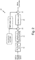
- FIG. 2 is a block diagram of an embodiment of a system for controlling braking power based on volatility of wheel slip.
- brake control system 20 includes de-trend module 22, volatility calculator 24, volatility comparator 26, controller 28, and perturbation summer 30.
- Brake control system 10 receives wheel-slip data that indicates the ratio of a difference between wheel rotational speed and ground speed to ground speed.
- the wheel-slip data is received by de-trend module 22.
- De-trend module 22 removes high-frequency components of the received wheel-slip data.
- de-trend module 22 can include a low-pass filter so as to perform the de-trend operation.
- the wheel-slip data includes high-frequency components that are passed by de-trend module 22 to volatility calculator 24.
- Volatility calculator 24 performs a measurement of the magnitude of the high-frequency components of the wheel-slip data (e.g., a measure of volatility) passed thereto.
- various measurements of the magnitude of the high-frequency components can be made, including, for example, a measurement of AC power and/or a peak-to-peak measurement.
- volatility comparator 26 The measure of volatility of the wheel-slip data is then compared to a volatility target by volatility comparator 26.
- volatility comparator 26 generates a signal indicative of a difference between the measure of volatility and the volatility target.
- Volatility comparator 26 sends the generated difference signal to controller 28.
- Controller 28 then generates a brake control signal based on the received signal indicative of a difference between the measured volatility and the volatility target.
- the controller sends the brake control signal to perturbation summer 30.
- Perturbation summer 30 adds a high-frequency perturbation to the generated brake control signal so as to dither the braking mechanism about the braking power that is actuated based on the brake control signal. This dithering of the braking mechanism about the braking power set by the brake control signal that causes the high-frequency components of wheel slip to occur.
- FIG. 3 is a schematic diagram of an embodiment of a system for controlling braking power based on volatility of wheel slip.
- brake control system 20 depicted in FIG. 2 is realized schematically.
- Brake control system 20 includes de-trend module 22, volatility calculator 24, volatility comparator 26, and controller 28.
- perturbations are introduced by controller 28.
- wheel-slip data is received by de-trend module 22.
- De-trend module 22 removes the low-frequency trend component of the received wheel-slip data.
- the wheel-slip data includes high-frequency components that are passed by de-trend module 22 to volatility calculator 24.
- Volatility calculator 24 performs a measurement of the magnitude of the high-frequency components of the wheel-slip data (e.g., a measure of volatility) passed thereto. Volatility calculator 24 generates a signal indicative of the measure of volatility calculated and send the signal to both controller 28 and saturation module 29.
- a measure of volatility e.g., a measure of volatility
- Saturation module 29 saturates the received signal at predetermined levels, if the magnitude of the received signal is indicative of a measure of volatility that is greater than a predetermined maximum value or less than a predetermined minimum value.
- the saturated measure of volatility of the wheel-slip data is then compared to a volatility target by volatility comparator 26.
- Controller 28 receives, from volatility comparator 26, a signal indicative of a difference between the saturated measure of volatility and a predetermined volatility target.
- Controller 28 has Proportional channel 32 and Integrated channel 34, thereby forming a PI controller.
- Proportional channel 32 generates a signal indicative of the difference between the saturated measure of volatility and the volatility target.
- the gain of proportional channel is large so as to cause perturbations about the signal generated by integrated channel 34.
- Integrated channel 34 generates a signal indicative of the integrated difference between the saturated measure of volatility and the volatility target.
- the signal generated by integrated channel 34 includes the low-frequency trend component of the brake control signal sent to a braking mechanism.
- the signals generated by proportional channel 32 and integrated channel 34 are then summed and sent to saturation module 35.
- Saturation module 35 saturates the received PI signal at predetermined levels, if the magnitude of the received PI signal is greater than a predetermined maximum value or less than a predetermined minimum value. Saturation module 35 then sends the saturated PI signal to a braking mechanism.
- mode control module 36 controls operation of brake controller 20.
- mode control module 36 sends mode control signals to brake controller 20.
- Brake controller 30 then controls operation of Proportional and Integrated channels 32 and 34 in response to the received mode control signals.
- brake controller enables Proportional channel 32 and disables Integrated channel 34 when the wheel-slip data indicates operation in the stable regime (i.e., wheel slip is less than the critical value WS crit ).
- Integrated channel 34 is enabled when a skid detector detects that the wheel is in a skid mode.
- integrated channel 34 is reset when a brake pedal pressure exceeds a predetermined threshold.
- FIG. 4 is a graph indicating various braking metrics of a system for controlling braking power based on volatility of wheel slip.
- graph 40 includes horizontal axis 42 and vertical axes 44 and 46.
- Horizontal axis 42 is indicative of time (t).
- Vertical axis 44 is indicative of velocity (m/s).
- Vertical axis 46 is indicative of braking torque coefficient ( ⁇ ).
- Graph 40 depicts a simulation of a brake control system of the FIG. 3 depicted schematic diagram.
- Graph 40 also depicts rotational wheel velocity 48, ground speed 50, braking torque coefficient 52, and maximum braking torque coefficient 54 as functions of time.
- a simulated aircraft wheel has made contact with a runway and has assumed a rotational wheel velocity 48 equal to the ground speed 50 of the aircraft, as indicated by rotational wheel velocity 48 and ground speed 50.
- Rotational wheel velocity and ground speed are equal to one another between times T, and T 2 .
- braking torque coefficient 52 is approximately zero, thereby indicating that little if any braking power is being applied by a braking mechanism to the wheel of the aircraft.
- brake power begins to be applied by the braking mechanism, as indicated by the suddenly increasing value of braking torque coefficient 52.
- Rotational wheel velocity 48 and ground speed 50 also begin to decrease after time T 2 .
- rotational wheel velocity 48 suddenly decreases to a value much less than ground speed 50.
- Such a sudden separation between rotational wheel velocity 48 and ground speed 50 can be indicative of a skid.
- the difference between rotational wheel velocity 48 and ground speed 50 is wheel slip.
- brake controller 28 (depicted in FIG. 3 ) begins to control the braking power, based on volatility of wheel skid.
- a perturbation signal is added to the brake control signal sent to the braking mechanism and the brake control signal is reduced so as to terminate skidding.
- Rotational wheel velocity 48 again approaches values substantially equal to ground speed 50.
- Braking torque coefficient 52 dips to a value around 0.4 and closed loop control begins.
- braking torque coefficient 52 soon climbs to a value of 0.7 where it is maintained for the remaining duration of braking operation.
- both rotational wheel velocity 48 and ground speed 50 monotonically decrease until both speeds 48 and 50 are reduced to zero. At zero speed, the aircraft is stopped.
- rotational wheel velocity 48 and ground speed 50 are modestly separated from one another. This separation is indicative of wheel slip.
- the controlled wheel slip during this time period after time T 3 is the wheel slip corresponding to the controlled braking torque coefficient of 0.7.
- FIG. 5 is a graph indicating various intermediate metrics of a system for controlling braking power based on volatility of wheel slip.
- Graph 60 depicted in FIG. 5 shows intermediate calculations corresponding to the simulation whose braking metrics are depicted in FIG. 4 .
- graph 60 includes horizontal axis 62 and vertical axes 64 and 66.
- Horizontal axis 62 is indicative of time (t).
- Vertical axis 64 is indicative of wheel slip.
- Vertical axis 66 is indicative of volatility.
- Graph 60 again depicts simulation results of a brake control system of the FIG. 3 depicted schematic diagram.
- Graph 60 also depicts wheel slip ratio 68, volatility 70, and volatility target 72 as functions of time.
- a simulated aircraft wheel has made contact with a runway and has assumed a rotational velocity equal to the ground velocity of the aircraft.
- wheel slip ratio 68 is at 0.01 and volatility (of wheel slip) is near zero. Wheel slip ratio 68 and volatility remain at these values between times T 1 and T 2 .
- brake power begins to be applied by the braking mechanism, as indicated by the suddenly increasing value of wheel slip ratio 68. Wheel slip ratio 68 increases until it reaches a value of 0.75 - a value greater than the critical value WS crit .
- brake controller 28 (depicted in FIG. 3 ) begins to control braking power based on volatility 70.
- brake controller 28 reduces the braking power, thereby reducing wheel slip ratio 68.
- wheel slip ratio 68 is reduced to a value of approximately 0.35, which is approximately equal or even less than to the critical value WS crit .
- brake controller 28 is in closed-loop control of braking system 20 (as depicted in FIG. 3 ).
- the oscillations of volatility 70 about volatility target 72 indicate that the brake control signal generated by the brake controller causes the brake mechanism to decrease the braking power if the calculated measure of volatility is greater than the volatility target. Conversely, the brake control signal generated by the brake controller causes the brake mechanism to increase the braking power if the magnitude of the calculated measure of volatility is less than the volatility target.
- Apparatus and associated methods relate to a system for maintaining near-peak friction of a wheel/ground interface during a braking operation of a wheeled vehicle.
- the system includes a perturbation controller configured to provide a high-frequency perturbation signal to a brake mechanism so as to cause the brake mechanism to dither braking power.
- the system includes a slip detector configured to determine wheel slip based on a difference between ground speed and rotation speed of the wheel.
- the system includes a volatility calculator configured to calculate a measure of volatility of the wheel slip based on a high-frequency component of the determined wheel slip.
- the system also includes a brake controller configured to generate a brake control signal for transmission to the brake mechanism of the wheel based, at least in part, on the calculated measure of volatility.
- the system of the preceding paragraph can optionally include, additionally and/or alternatively, any one or more of the following features, configurations and/or additional components:
- brake controller can be configured to compare the calculated measure of volatility with a predetermined volatility target.
- the brake control signal generated by the brake controller can be configured to cause the brake mechanism to decrease the braking power if the calculated measure of volatility is greater than the predetermined volatility target.
- the brake control signal generated by the brake controller can be configured to cause the brake mechanism to increase the braking power if the magnitude of the calculated measure of volatility is less than the predetermined volatility target.
- a further embodiment of any of the foregoing systems can further include a skid detector configured to detect a skid based on the determined wheel slip.
- skid detector can be further configured to compare the determined wheel slip with a predetermined slip threshold.
- skid detector can be configured to detect a skid if the determined wheel slip is greater than the predetermined slip threshold.
- system can be configured to begin maintaining peak friction of the wheel/ground interface in response to the skid detector having detected a skid.
- the brake controller can include a proportional channel configured to generate a signal proportional to a difference between the calculated measure of volatility and a selected volatility target.
- proportional channel can be configured to have a saturation limit that determines the calculated measure of volatility.
- proportional channel can have a channel gain that is greater than a target value so as to cause the small-signal high-frequency perturbation signal in closed-loop operation of the system.
- the brake controller can include an integrated channel configured to generate a signal proportional to an integrated difference between the calculated measure of volatility and a predetermined volatility target.
- Some embodiments relate to a method for maintaining near-peak friction of wheel/ground interface during a braking operation of a wheeled vehicle.
- the method includes providing, by a perturbation controller, a small-signal high-frequency perturbation signal to a brake mechanism so as to cause the brake mechanism to dither braking power.
- the method includes determining, by a slip detector, wheel slip based on a difference between ground speed and rotation speed of the wheel.
- the method includes calculating, by a volatility calculator, a measure of volatility of wheel slip based on a small-signal high-frequency component of the determined wheel slip.
- the method also includes generating, by a brake controller, a brake control signal for transmission to the brake mechanism of the wheel based, at least in part, on the calculated measure of volatility.
- the method of the preceding paragraph can optionally include, additionally and/or alternatively, any one or more of the following features, configurations and/or additional components:
- a further embodiment of the foregoing method can further include comparing, by the brake controller, the calculated measure of volatility with a predetermined volatility target.
- the brake control signal generated by the brake controller can be configured to cause the brake mechanism to decrease the braking power if the calculated measure of volatility is greater than the predetermined volatility target.
- the brake control signal generated by the brake controller can be configured to cause the brake mechanism to increase the braking power if the magnitude of the calculated measure of volatility is less than the predetermined volatility target.
- a further embodiment of any of the foregoing methods can further include detecting, by a skid detector, a skid based on the determined wheel slip.
- a further embodiment of any of the foregoing methods can further include comparing, by the skid detector, the determined wheel slip with a predetermined slip threshold.
- skid detector can be configured to detect a skid if the determined wheel slip is greater than the predetermined slip threshold.
- system can be configured to begin maintaining peak friction of the wheel/ground interface in response to the skid detector having detected a skid.
Landscapes
- Engineering & Computer Science (AREA)
- Transportation (AREA)
- Mechanical Engineering (AREA)
- Microelectronics & Electronic Packaging (AREA)
- Physics & Mathematics (AREA)
- Fluid Mechanics (AREA)
- Aviation & Aerospace Engineering (AREA)
- Regulating Braking Force (AREA)
Abstract
Description
- Many vehicles are equipped with various types of braking systems. Wheeled vehicles can be equipped with a disk brake system, a drum brake system, engine brake systems, electrical-energy harvesting systems, other types of braking systems, or combinations of such systems. For wheeled vehicles, each type of braking system is ultimately limited by a peak value of friction of the ground/wheel interface.
- The efficacy of a braking system is therefore limited by this ground/wheel interface. The friction of the ground/wheel interface can depend on many factors. For example, the tire condition, the road condition, the vehicle dynamics, etc. can all affect the friction of the ground/wheel interface, and can therefore affect braking efficacy.
- Some of the factors that affect the friction of the ground/wheel interface are independent of the specific wheeled vehicle and independent of the specific braking system of such wheeled vehicle. For example, road conditions can be affected by pavement material, debris on the pavement, and weather conditions. Weather conditions can dramatically affect road conditions. For example, rain, snow, and ice can dramatically change the friction of the ground/wheel interface.
- The friction of the ground/wheel interface can also vary in as a function of wheel slip. Wheel slip is difference between ground speed and a rotation speed of the wheel. The rotation speed of a wheel, during a braking operation, is not necessarily equal to the ground speed. When a wheeled vehicle is coasting, the rotation speed of the wheel is approximately equal to the ground speed. When, modest brake power is applied, however, the elasticity of the tire causes it to deform in response to forces induced by the braking operation. Such tire deformation can reduce the effective circumference of the tire, thereby reducing the rotation speed of the tire with respect to the ground speed. If sufficient braking power is applied, the tire can skid with respect to the ground surface, further increasing slip ratio.
- Apparatus and associated methods relate to a system for maintaining peak friction of wheel/ground interface during a braking operation of a wheeled vehicle. The system includes a perturbation controller configured to provide a small-signal high-frequency perturbation signal to a brake mechanism so as to cause the brake mechanism to dither braking power. The system includes a slip detector configured to determine wheel slip based on a difference between ground speed and rotation speed of the wheel. The system includes a volatility calculator configured to calculate a measure of volatility of wheel slip based on a small-signal high-frequency component of the determined wheel slip. The system also includes a brake controller configured to generate a brake control signal for transmission to the brake mechanism of the wheel based, at least in part, on the calculated measure of volatility.
- Some embodiments relate to a method for maintaining peak friction of wheel/ground interface during a braking operation of a wheeled vehicle. The method includes providing, by a perturbation controller, a small-signal high-frequency perturbation signal to a brake mechanism so as to cause the brake mechanism to dither braking power. Then, wheel slip is determined, by a slip detector, based on a difference between ground speed and rotation speed of the wheel. A measure of volatility of wheel slip is calculated, by a volatility calculator, volatility based on a small-signal high-frequency component of the determined wheel slip. Then a brake control signal is generated, by a brake controller, for transmission to the brake mechanism of the wheel based, at least in part, on the calculated measure of volatility.
-
-
FIG. 1 is a graph depicting the relationship between braking torque coefficient and wheel slip. -
FIG. 2 is a block diagram of an embodiment of a system for controlling braking power based on volatility of wheel slip. -
FIG. 3 is a schematic diagram of an embodiment of a system for controlling braking power based on volatility of wheel slip. -
FIG. 4 is a graph indicating various braking metrics of a system for controlling braking power based on volatility of wheel slip. -
FIG. 5 is a graph indicating various intermediate metrics of a system for controlling braking power based on volatility of wheel slip. - Apparatus and associated methods relate to controlling a brake mechanism during braking operation to provide near-maximal braking power. Maximal braking power occurs when the wheel slip has a target value. Wheel slip can be monitored during braking operation so as to be used to control the brake mechanism to operate at the maximal braking power. The braking power is modulated so as to dither the braking power about a nominal braking power. The monitored wheel slip will have a dither component in response to the dithering of the braking power. A volatility of the dither component of the monitored wheel slip can be indicative of nominal braking power proximity to the maximal braking power. A nominal brake signal can be generated so as to change the nominal braking power in the direction of the maximal braking power based on the volatility of the dither component of the monitored wheel slip.
-
FIG. 1 is a graph depicting the relationship between braking torque coefficient and wheel slip. InFIG. 1 ,graph 10 hashorizontal axis 12 andvertical axis 14.Horizontal axis 12 is indicative of a measure of wheel slip as given by (ωtirertire-vgs)/vgs. Here, ωtire is the angular rotational velocity of a tire of the wheel, rtire is the radius of the tire of the wheel, and vgs is a ground speed of the vehicle to which the wheel belongs.Vertical axis 14 is indicative of a measure of braking torque coefficient as given by Ft/Nv. Here, Ft is the tire tractive or braking force, and Nv is the normal force of the vehicle. The normal force Nv can be thought of as force of the wheel directed vertically upon the ground surface. Such a force is affected by vehicle weight, payload weight, lift, center of gravity, location of the wheel and other vehicle dynamics. - Braking torque coefficient/
wheel slip relation 16 is shown ongraph 10 to indicate a functional relationship between braking torque coefficient and wheel slip. As indicated inrelation 16, braking torque coefficient is zero when wheel slip is zero. This indicates that when the wheel is freely rotating without locomotion or application of braking power, both wheel slip and braking torque coefficient are zero. Then, as braking power is applied to the system, both wheel slip and the braking torque coefficient increases. The braking torque coefficient increases in response to increasing wheel slip critical point (BTcrit, WScrit). At critical wheel slip WScrit, critical braking torque coefficient BTcrit is at a maximum value. As braking power is further increased causing wheel slip to increase to values greater than critical wheel slip WScrit, the braking torque coefficient decreases to values less than critical braking torque coefficient BTcrit. - The consequences of such a braking torque coefficient/
wheel slip relation 16 as indicated ingraph 10 are many. First, as a braking system is operated at braking powers that are low, so as to cause wheel slip values that are less than WScrit, the braking system is operating in a stable regime. When the braking system is operated at braking powers that are high, so as to cause wheel slip values that are greater than WScrit, the braking system is operating in an unstable regime. - If, for example, the braking power is applied so as cause operation at operating point PI as indicated on
relation 16, the braking system is being operated in the stable regime. At operating point PI, the vehicle is decelerating at a rate proportional to the braking force as computed using the braking torque coefficient indicated at operating point P1. A small additional increase in braking power will cause the operating point to shift to an operating point that has a slightly greater value of wheel slip and a greater value of braking torque coefficient. This in turn will cause the vehicle to decelerate at a rate proportional to the braking force computed using a greater value of braking torque coefficient than that indicated at operating point PI. In short, braking force will be increased. - If, however, the braking power is applied so as cause operation at operating point P2 as indicated on
relation 16, the braking system is being operated in the unstable regime. At operating point P2, the vehicle is decelerating at a rate proportional to the braking force as computed using the braking torque coefficient indicated at operating point P2. A small additional increase in braking power will cause the operating point to shift to an operating point that has a slightly greater value of wheel slip but a lower value of braking torque coefficient. This in turn will cause the vehicle to decelerate at a rate proportional to the braking force computed using a lower value of braking torque coefficient than that indicated at operating point P2. In short, braking force will be decreased. Because the braking force is decreased, the brake mechanism of the wheel can lock up, thereby causing the wheel slip to further increase. Such further increase in the value of wheel slip further reduces the breaking torque coefficient. -
FIG. 2 is a block diagram of an embodiment of a system for controlling braking power based on volatility of wheel slip. InFIG. 2 ,brake control system 20 includesde-trend module 22,volatility calculator 24,volatility comparator 26,controller 28, andperturbation summer 30.Brake control system 10 receives wheel-slip data that indicates the ratio of a difference between wheel rotational speed and ground speed to ground speed. The wheel-slip data is received byde-trend module 22.De-trend module 22, removes high-frequency components of the received wheel-slip data. In some embodiments,de-trend module 22 can include a low-pass filter so as to perform the de-trend operation. The wheel-slip data includes high-frequency components that are passed byde-trend module 22 tovolatility calculator 24.Volatility calculator 24 performs a measurement of the magnitude of the high-frequency components of the wheel-slip data (e.g., a measure of volatility) passed thereto. In various embodiments, various measurements of the magnitude of the high-frequency components can be made, including, for example, a measurement of AC power and/or a peak-to-peak measurement. - The measure of volatility of the wheel-slip data is then compared to a volatility target by
volatility comparator 26. In the embodiment depicted inFIG. 2 ,volatility comparator 26 generates a signal indicative of a difference between the measure of volatility and the volatility target.Volatility comparator 26 sends the generated difference signal tocontroller 28.Controller 28 then generates a brake control signal based on the received signal indicative of a difference between the measured volatility and the volatility target. The controller sends the brake control signal toperturbation summer 30.Perturbation summer 30 adds a high-frequency perturbation to the generated brake control signal so as to dither the braking mechanism about the braking power that is actuated based on the brake control signal. This dithering of the braking mechanism about the braking power set by the brake control signal that causes the high-frequency components of wheel slip to occur. -
FIG. 3 is a schematic diagram of an embodiment of a system for controlling braking power based on volatility of wheel slip. InFIG. 3 , an embodiment ofbrake control system 20 depicted inFIG. 2 is realized schematically.Brake control system 20 includesde-trend module 22,volatility calculator 24,volatility comparator 26, andcontroller 28. In theFIG. 3 embodiment, perturbations are introduced bycontroller 28. Again, wheel-slip data is received byde-trend module 22.De-trend module 22 removes the low-frequency trend component of the received wheel-slip data. The wheel-slip data includes high-frequency components that are passed byde-trend module 22 tovolatility calculator 24.Volatility calculator 24 performs a measurement of the magnitude of the high-frequency components of the wheel-slip data (e.g., a measure of volatility) passed thereto.Volatility calculator 24 generates a signal indicative of the measure of volatility calculated and send the signal to bothcontroller 28 andsaturation module 29. -
Saturation module 29 saturates the received signal at predetermined levels, if the magnitude of the received signal is indicative of a measure of volatility that is greater than a predetermined maximum value or less than a predetermined minimum value. The saturated measure of volatility of the wheel-slip data is then compared to a volatility target byvolatility comparator 26.Controller 28 then receives, fromvolatility comparator 26, a signal indicative of a difference between the saturated measure of volatility and a predetermined volatility target.Controller 28 hasProportional channel 32 and Integrated channel 34, thereby forming a PI controller.Proportional channel 32 generates a signal indicative of the difference between the saturated measure of volatility and the volatility target. In some embodiments, the gain of proportional channel is large so as to cause perturbations about the signal generated by integrated channel 34. - Integrated channel 34 generates a signal indicative of the integrated difference between the saturated measure of volatility and the volatility target. In some embodiments, the signal generated by integrated channel 34 includes the low-frequency trend component of the brake control signal sent to a braking mechanism. The signals generated by
proportional channel 32 and integrated channel 34 are then summed and sent tosaturation module 35.Saturation module 35 saturates the received PI signal at predetermined levels, if the magnitude of the received PI signal is greater than a predetermined maximum value or less than a predetermined minimum value.Saturation module 35 then sends the saturated PI signal to a braking mechanism. - Also depicted in the
FIG. 3 embodiment ismode control module 36.Mode control module 36 controls operation ofbrake controller 20. In some embodiments,mode control module 36 sends mode control signals to brakecontroller 20.Brake controller 30 then controls operation of Proportional andIntegrated channels 32 and 34 in response to the received mode control signals. For example, in some embodiments, brake controller enablesProportional channel 32 and disables Integrated channel 34 when the wheel-slip data indicates operation in the stable regime (i.e., wheel slip is less than the critical value WScrit). In some embodiments, Integrated channel 34 is enabled when a skid detector detects that the wheel is in a skid mode. In some embodiments, integrated channel 34 is reset when a brake pedal pressure exceeds a predetermined threshold. -
FIG. 4 is a graph indicating various braking metrics of a system for controlling braking power based on volatility of wheel slip. InFIG. 4 ,graph 40 includeshorizontal axis 42 andvertical axes Horizontal axis 42 is indicative of time (t).Vertical axis 44 is indicative of velocity (m/s).Vertical axis 46 is indicative of braking torque coefficient (µ).Graph 40 depicts a simulation of a brake control system of theFIG. 3 depicted schematic diagram.Graph 40 also depictsrotational wheel velocity 48,ground speed 50, brakingtorque coefficient 52, and maximumbraking torque coefficient 54 as functions of time. - At time T1, a simulated aircraft wheel has made contact with a runway and has assumed a
rotational wheel velocity 48 equal to theground speed 50 of the aircraft, as indicated byrotational wheel velocity 48 andground speed 50. Rotational wheel velocity and ground speed are equal to one another between times T, and T2. Between time T1 and T2, brakingtorque coefficient 52 is approximately zero, thereby indicating that little if any braking power is being applied by a braking mechanism to the wheel of the aircraft. At time T2, brake power begins to be applied by the braking mechanism, as indicated by the suddenly increasing value of brakingtorque coefficient 52.Rotational wheel velocity 48 andground speed 50 also begin to decrease after time T2. - Then, at time T3,
rotational wheel velocity 48 suddenly decreases to a value much less thanground speed 50. Such a sudden separation betweenrotational wheel velocity 48 andground speed 50 can be indicative of a skid. The difference betweenrotational wheel velocity 48 andground speed 50 is wheel slip. Immediately after the skid is initiated, brake controller 28 (depicted inFIG. 3 ) begins to control the braking power, based on volatility of wheel skid. A perturbation signal is added to the brake control signal sent to the braking mechanism and the brake control signal is reduced so as to terminate skidding.Rotational wheel velocity 48 again approaches values substantially equal toground speed 50. Brakingtorque coefficient 52 dips to a value around 0.4 and closed loop control begins. - As indicated in
graph 40, brakingtorque coefficient 52 soon climbs to a value of 0.7 where it is maintained for the remaining duration of braking operation. After time T3, bothrotational wheel velocity 48 andground speed 50 monotonically decrease until both speeds 48 and 50 are reduced to zero. At zero speed, the aircraft is stopped. After time T3,rotational wheel velocity 48 andground speed 50 are modestly separated from one another. This separation is indicative of wheel slip. The controlled wheel slip during this time period after time T3 is the wheel slip corresponding to the controlled braking torque coefficient of 0.7. -
FIG. 5 is a graph indicating various intermediate metrics of a system for controlling braking power based on volatility of wheel slip.Graph 60 depicted inFIG. 5 shows intermediate calculations corresponding to the simulation whose braking metrics are depicted inFIG. 4 . InFIG. 5 ,graph 60 includeshorizontal axis 62 andvertical axes Horizontal axis 62 is indicative of time (t).Vertical axis 64 is indicative of wheel slip.Vertical axis 66 is indicative of volatility.Graph 60 again depicts simulation results of a brake control system of theFIG. 3 depicted schematic diagram.Graph 60 also depictswheel slip ratio 68,volatility 70, andvolatility target 72 as functions of time. - At time T1, a simulated aircraft wheel has made contact with a runway and has assumed a rotational velocity equal to the ground velocity of the aircraft. At time T1,
wheel slip ratio 68 is at 0.01 and volatility (of wheel slip) is near zero.Wheel slip ratio 68 and volatility remain at these values between times T1 and T2. At time T2, brake power begins to be applied by the braking mechanism, as indicated by the suddenly increasing value ofwheel slip ratio 68.Wheel slip ratio 68 increases until it reaches a value of 0.75 - a value greater than the critical value WScrit. At this value of wheel slip, a skid begins and brake controller 28 (depicted inFIG. 3 ) begins to control braking power based onvolatility 70. Between times T2 and T3,brake controller 28 reduces the braking power, thereby reducingwheel slip ratio 68. At time T3,wheel slip ratio 68 is reduced to a value of approximately 0.35, which is approximately equal or even less than to the critical value WScrit. At times greater than T3,brake controller 28 is in closed-loop control of braking system 20 (as depicted inFIG. 3 ). - The oscillations of
volatility 70 aboutvolatility target 72 indicate that the brake control signal generated by the brake controller causes the brake mechanism to decrease the braking power if the calculated measure of volatility is greater than the volatility target. Conversely, the brake control signal generated by the brake controller causes the brake mechanism to increase the braking power if the magnitude of the calculated measure of volatility is less than the volatility target. - The following are non-exclusive descriptions of possible embodiments of the present invention.
- Apparatus and associated methods relate to a system for maintaining near-peak friction of a wheel/ground interface during a braking operation of a wheeled vehicle. The system includes a perturbation controller configured to provide a high-frequency perturbation signal to a brake mechanism so as to cause the brake mechanism to dither braking power. The system includes a slip detector configured to determine wheel slip based on a difference between ground speed and rotation speed of the wheel. The system includes a volatility calculator configured to calculate a measure of volatility of the wheel slip based on a high-frequency component of the determined wheel slip. The system also includes a brake controller configured to generate a brake control signal for transmission to the brake mechanism of the wheel based, at least in part, on the calculated measure of volatility.
- The system of the preceding paragraph can optionally include, additionally and/or alternatively, any one or more of the following features, configurations and/or additional components:
- A further embodiment of the foregoing system, wherein the brake controller can be configured to compare the calculated measure of volatility with a predetermined volatility target.
- A further embodiment of any of the foregoing systems, wherein the brake control signal generated by the brake controller can be configured to cause the brake mechanism to decrease the braking power if the calculated measure of volatility is greater than the predetermined volatility target.
- A further embodiment of any of the foregoing systems, wherein the brake control signal generated by the brake controller can be configured to cause the brake mechanism to increase the braking power if the magnitude of the calculated measure of volatility is less than the predetermined volatility target.
- A further embodiment of any of the foregoing systems can further include a skid detector configured to detect a skid based on the determined wheel slip.
- A further embodiment of any of the foregoing systems, wherein the skid detector can be further configured to compare the determined wheel slip with a predetermined slip threshold.
- A further embodiment of any of the foregoing systems, wherein the skid detector can be configured to detect a skid if the determined wheel slip is greater than the predetermined slip threshold.
- A further embodiment of any of the foregoing systems, wherein the system can be configured to begin maintaining peak friction of the wheel/ground interface in response to the skid detector having detected a skid.
- A further embodiment of any of the foregoing systems, wherein the brake controller can include a proportional channel configured to generate a signal proportional to a difference between the calculated measure of volatility and a selected volatility target.
- A further embodiment of any of the foregoing systems, wherein the proportional channel can be configured to have a saturation limit that determines the calculated measure of volatility.
- A further embodiment of any of the foregoing systems, wherein the proportional channel can have a channel gain that is greater than a target value so as to cause the small-signal high-frequency perturbation signal in closed-loop operation of the system.
- A further embodiment of any of the foregoing systems, wherein the brake controller can include an integrated channel configured to generate a signal proportional to an integrated difference between the calculated measure of volatility and a predetermined volatility target.
- Some embodiments relate to a method for maintaining near-peak friction of wheel/ground interface during a braking operation of a wheeled vehicle. The method includes providing, by a perturbation controller, a small-signal high-frequency perturbation signal to a brake mechanism so as to cause the brake mechanism to dither braking power. The method includes determining, by a slip detector, wheel slip based on a difference between ground speed and rotation speed of the wheel. The method includes calculating, by a volatility calculator, a measure of volatility of wheel slip based on a small-signal high-frequency component of the determined wheel slip. The method also includes generating, by a brake controller, a brake control signal for transmission to the brake mechanism of the wheel based, at least in part, on the calculated measure of volatility.
- The method of the preceding paragraph can optionally include, additionally and/or alternatively, any one or more of the following features, configurations and/or additional components:
- A further embodiment of the foregoing method can further include comparing, by the brake controller, the calculated measure of volatility with a predetermined volatility target.
- A further embodiment of any of the foregoing methods, wherein the brake control signal generated by the brake controller can be configured to cause the brake mechanism to decrease the braking power if the calculated measure of volatility is greater than the predetermined volatility target.
- A further embodiment of any of the foregoing methods, wherein the brake control signal generated by the brake controller can be configured to cause the brake mechanism to increase the braking power if the magnitude of the calculated measure of volatility is less than the predetermined volatility target.
- A further embodiment of any of the foregoing methods can further include detecting, by a skid detector, a skid based on the determined wheel slip.
- A further embodiment of any of the foregoing methods can further include comparing, by the skid detector, the determined wheel slip with a predetermined slip threshold.
- A further embodiment of any of the foregoing methods, wherein the skid detector can be configured to detect a skid if the determined wheel slip is greater than the predetermined slip threshold.
- A further embodiment of any of the foregoing methods, wherein the system can be configured to begin maintaining peak friction of the wheel/ground interface in response to the skid detector having detected a skid.
- While the invention has been described with reference to an exemplary embodiment(s), it will be understood by those skilled in the art that various changes may be made and equivalents may be substituted for elements thereof without departing from the scope of the invention as defined by the claims. In addition, many modifications may be made to adapt a particular situation or material to the teachings of the invention without departing from the scope thereof. Therefore, it is intended that the invention not be limited to the particular embodiment(s) disclosed, but that the invention will include all embodiments falling within the scope of the appended claims.
Claims (15)
- A system for maintaining near-peak friction of a wheel/ground interface during a braking operation of a wheeled vehicle, the system comprising:a perturbation controller (28) configured to provide a high-frequency perturbation signal to a brake mechanism so as to cause the brake mechanism to dither braking power;a slip detector (22) configured to determine wheel slip based on a difference between ground speed and rotation speed of the wheel;a volatility calculator (24) configured to calculate a measure of volatility of the wheel slip based on a high-frequency component of the determined wheel slip; anda brake controller (30) configured to generate a brake control signal for transmission to the brake mechanism of the wheel based, at least in part, on the calculated measure of volatility.
- The system of claim 1, wherein the brake controller is configured to compare the calculated measure of volatility with a predetermined volatility target.
- The system of claim 2, wherein the brake control signal generated by the brake controller is configured to cause the brake mechanism to decrease the braking power if the calculated measure of volatility is greater than the predetermined volatility target, or wherein the brake control signal generated by the brake controller is configured to cause the brake mechanism to increase the braking power if the magnitude of the calculated measure of volatility is less than the predetermined volatility target.
- The system of any preceding claim, further comprising:a skid detector configured to detect a skid based on the determined wheel slip.
- The system of claim 4, wherein the skid detector is further configured to compare the determined wheel slip with a predetermined slip threshold.
- The system of claim 5, wherein the skid detector is configured to detect a skid if the determined wheel slip is greater than the predetermined slip threshold.
- The system of claim 4, 5 or 6, wherein the system is configured to begin maintaining peak friction of the wheel/ground interface in response to the skid detector having detected a skid.
- The system of any preceding claim, wherein the brake controller includes:a proportional channel (32) configured to generate a signal proportional to a difference between the calculated measure of volatility and a selected volatility target.
- The system of claim 8, wherein the proportional channel is configured to have a saturation limit that determines the calculated measure of volatility.
- The system of claim 8, wherein the proportional channel has a channel gain that is greater than a target value so as to cause the small-signal high-frequency perturbation signal in closed-loop operation of the system.
- The system of any preceding claim, wherein the brake controller includes:an integrated channel (34) configured to generate a signal proportional to an integrated difference between the calculated measure of volatility and a predetermined volatility target.
- A method for maintaining near-peak friction of wheel/ground interface during a braking operation of a wheeled vehicle, the method comprising:providing, by a perturbation controller, a small-signal high-frequency perturbation signal to a brake mechanism so as to cause the brake mechanism to dither braking power;determining, by a slip detector, wheel slip based on a difference between ground speed and rotation speed of the wheel;calculating, by a volatility calculator, a measure of volatility of wheel slip based on a small-signal high-frequency component of the determined wheel slip; andgenerating, by a brake controller, a brake control signal for transmission to the brake mechanism of the wheel based, at least in part, on the calculated measure of volatility.
- The method of claim 12, further comprising:comparing, by the brake controller, the calculated measure of volatility with a predetermined volatility target.
- The method of claim 13, wherein the brake control signal generated by the brake controller is configured to cause the brake mechanism to decrease the braking power if the calculated measure of volatility is greater than the predetermined volatility target, or wherein the brake control signal generated by the brake controller is configured to cause the brake mechanism to increase the braking power if the magnitude of the calculated measure of volatility is less than the predetermined volatility target.
- The method of claim 12, 13 or 14, further comprising:detecting, by a skid detector, a skid based on the determined wheel slip, and preferably further comprising:comparing, by the skid detector, the determined wheel slip with a predetermined slip threshold; and preferably wherein the skid detector is configured to detect a skid if the determined wheel slip is greater than the predetermined slip threshold.
Applications Claiming Priority (1)
| Application Number | Priority Date | Filing Date | Title |
|---|---|---|---|
| US201862619307P | 2018-01-19 | 2018-01-19 |
Publications (2)
| Publication Number | Publication Date |
|---|---|
| EP3514027A1 true EP3514027A1 (en) | 2019-07-24 |
| EP3514027B1 EP3514027B1 (en) | 2022-01-05 |
Family
ID=65138874
Family Applications (1)
| Application Number | Title | Priority Date | Filing Date |
|---|---|---|---|
| EP19152753.0A Active EP3514027B1 (en) | 2018-01-19 | 2019-01-21 | System for maintaining near-peak friction of a braking wheel |
Country Status (2)
| Country | Link |
|---|---|
| US (1) | US10807579B2 (en) |
| EP (1) | EP3514027B1 (en) |
Cited By (1)
| Publication number | Priority date | Publication date | Assignee | Title |
|---|---|---|---|---|
| US10807579B2 (en) * | 2018-01-19 | 2020-10-20 | Goodrich Corporation | System for maintaining near-peak friction of a braking wheel |
Families Citing this family (1)
| Publication number | Priority date | Publication date | Assignee | Title |
|---|---|---|---|---|
| US20240383339A1 (en) * | 2021-06-01 | 2024-11-21 | Volvo Truck Corporation | Energy efficient propulsion based on wheel slip balanced drive |
Citations (4)
| Publication number | Priority date | Publication date | Assignee | Title |
|---|---|---|---|---|
| EP0825080A2 (en) * | 1996-08-20 | 1998-02-25 | Kabushiki Kaisha Toyota Chuo Kenkyusho | Anti-lock braking system |
| US20030025035A1 (en) * | 2001-05-23 | 2003-02-06 | Duk-Hyun Park | Optimal control design for aircraft antiskid brake control systems |
| US20070222285A1 (en) * | 2006-03-08 | 2007-09-27 | Ribbens William B | Antilock braking systems and methods |
| FR2924392A3 (en) * | 2007-12-03 | 2009-06-05 | Renault Sas | SYSTEM FOR GENERATING SLIDING INSTRUCTIONS OF A MOTOR VEHICLE EQUIPPED WITH AN ANTI-LOCK BRAKING DEVICE. |
Family Cites Families (34)
| Publication number | Priority date | Publication date | Assignee | Title |
|---|---|---|---|---|
| US5305165A (en) * | 1991-12-24 | 1994-04-19 | International Business Machines Corporation | Tribo-attractive contact data storage system |
| US5424948A (en) * | 1993-11-10 | 1995-06-13 | General Motors Corporation | Locomotive traction control system using fuzzy logic |
| JP3367277B2 (en) * | 1995-06-05 | 2003-01-14 | 株式会社豊田中央研究所 | Friction state detecting device and power steering device |
| US5951122A (en) | 1997-12-31 | 1999-09-14 | The B.F. Goodrich Company | Antiskid control and wheel lock protection differential reference controller |
| US6125318A (en) | 1998-02-12 | 2000-09-26 | The B. F. Goodrich Company | Slip ratio antiskid controller using mu/slip ratio generated velocity reference |
| KR100636020B1 (en) * | 2001-09-19 | 2006-10-18 | 인벤텍 어플라이언시스 코퍼레이션 | Method for communication device controlling time switch using GPS |
| GB0213372D0 (en) * | 2002-06-11 | 2002-07-24 | Airbus Uk Ltd | Aircraft braking method and apparatus |
| EP1603781B1 (en) * | 2003-02-28 | 2012-04-18 | Kelsey-Hayes Company | An anti-lock brake system with continuous wheel slip control |
| US6882920B2 (en) * | 2003-04-29 | 2005-04-19 | Goodrich Corporation | Brake control system |
| US20050038588A1 (en) * | 2003-08-14 | 2005-02-17 | Deepak Shukla | Vehicle driving force control method |
| US7040958B2 (en) * | 2004-05-21 | 2006-05-09 | Mosel Vitelic, Inc. | Torque-based end point detection methods for chemical mechanical polishing tool which uses ceria-based CMP slurry to polish to protective pad layer |
| JP2007047130A (en) * | 2005-08-12 | 2007-02-22 | Omron Corp | Friction characteristic measuring device and tire directed thereto |
| US8311311B2 (en) * | 2005-10-31 | 2012-11-13 | Mitutoyo Corporation | Optical aberration correction for machine vision inspection systems |
| RU2300717C1 (en) * | 2005-12-29 | 2007-06-10 | Михаил Юрьевич Савинов | Method and device for krypton-xenon mixture separation by rectification thereof |
| US8700516B2 (en) * | 2011-01-24 | 2014-04-15 | Axioma, Inc. | Methods and apparatus for improving factor risk model responsiveness |
| US20140012777A1 (en) * | 2012-01-24 | 2014-01-09 | John D. Freeman | System and method for volatility-based characterization of securities |
| US8725618B1 (en) * | 2012-11-09 | 2014-05-13 | Manulife Asset Management (US) LLC | System and method for de-risking a pension fund |
| JP5951122B2 (en) * | 2013-05-15 | 2016-07-13 | 三菱電機株式会社 | Cryptographic system, cryptographic method and cryptographic program |
| US20150081398A1 (en) * | 2013-09-17 | 2015-03-19 | International Business Machines Corporation | Determining a performance target setting |
| WO2015153811A1 (en) * | 2014-04-02 | 2015-10-08 | Levant Power Corporation | Active safety suspension system |
| CN104723341A (en) * | 2015-03-07 | 2015-06-24 | 哈尔滨工业大学 | Positioning control method for flexibility joint mechanical arm based on connection and damping configuration |
| US20170072850A1 (en) * | 2015-09-14 | 2017-03-16 | Pearl Automation Inc. | Dynamic vehicle notification system and method |
| US10035426B2 (en) * | 2016-03-10 | 2018-07-31 | Ford Global Technologies, Llc | Battery power management in hybrid vehicles |
| GB2556315A (en) * | 2016-03-23 | 2018-05-30 | Univ Coventry | Control system |
| US10293796B2 (en) * | 2016-07-14 | 2019-05-21 | Goodrich Corporation | Antiskid brake control system with minimum disruption autobrake function |
| US10248120B1 (en) * | 2016-09-16 | 2019-04-02 | Amazon Technologies, Inc. | Navigable path networks for autonomous vehicles |
| WO2018053825A1 (en) * | 2016-09-26 | 2018-03-29 | 深圳市大疆创新科技有限公司 | Focusing method and device, image capturing method and device, and camera system |
| JP6725391B2 (en) * | 2016-10-12 | 2020-07-15 | 富士フイルム株式会社 | Mobile radiation generator |
| US20180350000A1 (en) * | 2017-06-02 | 2018-12-06 | Nasdaq Technology Ab | Systems and methods for generating a graphical user interface displaying participant performance information |
| US10613533B1 (en) * | 2017-12-11 | 2020-04-07 | Amazon Technologies, Inc. | Autonomous delivery and retrieval of inventory holders at transfer locations |
| US10807579B2 (en) * | 2018-01-19 | 2020-10-20 | Goodrich Corporation | System for maintaining near-peak friction of a braking wheel |
| US10730491B2 (en) * | 2018-04-20 | 2020-08-04 | Goodrich Corporation | Energy-based antiskid brake control system |
| US10647306B2 (en) * | 2018-04-23 | 2020-05-12 | Goodrich Corporation | Measurement of contact maintaining control valve current for a hydraulic actuator |
| US11001238B2 (en) * | 2018-09-28 | 2021-05-11 | Goodrich Corporation | Hydraulic braking system and method |
-
2018
- 2018-10-05 US US16/152,921 patent/US10807579B2/en active Active
-
2019
- 2019-01-21 EP EP19152753.0A patent/EP3514027B1/en active Active
Patent Citations (4)
| Publication number | Priority date | Publication date | Assignee | Title |
|---|---|---|---|---|
| EP0825080A2 (en) * | 1996-08-20 | 1998-02-25 | Kabushiki Kaisha Toyota Chuo Kenkyusho | Anti-lock braking system |
| US20030025035A1 (en) * | 2001-05-23 | 2003-02-06 | Duk-Hyun Park | Optimal control design for aircraft antiskid brake control systems |
| US20070222285A1 (en) * | 2006-03-08 | 2007-09-27 | Ribbens William B | Antilock braking systems and methods |
| FR2924392A3 (en) * | 2007-12-03 | 2009-06-05 | Renault Sas | SYSTEM FOR GENERATING SLIDING INSTRUCTIONS OF A MOTOR VEHICLE EQUIPPED WITH AN ANTI-LOCK BRAKING DEVICE. |
Cited By (1)
| Publication number | Priority date | Publication date | Assignee | Title |
|---|---|---|---|---|
| US10807579B2 (en) * | 2018-01-19 | 2020-10-20 | Goodrich Corporation | System for maintaining near-peak friction of a braking wheel |
Also Published As
| Publication number | Publication date |
|---|---|
| US10807579B2 (en) | 2020-10-20 |
| US20190225201A1 (en) | 2019-07-25 |
| EP3514027B1 (en) | 2022-01-05 |
Similar Documents
| Publication | Publication Date | Title |
|---|---|---|
| CN1086173C (en) | System and method for adaptive brake application and initial skid detection | |
| JP4602081B2 (en) | System for adaptive brake application and initial skid detection | |
| US7775607B2 (en) | Antiskid control—combined paired/individual wheel control logic | |
| KR102575812B1 (en) | Apparatus and method for improving the performance of anti-lock braking and anti-slip control of vehicles | |
| EP0936115A2 (en) | Brake control systems and methods | |
| US6890041B1 (en) | Antilock brake systems employing a sliding mode observer based estimation of differential wheel torque | |
| US7286909B2 (en) | Aircraft braking method and apparatus | |
| US20070222285A1 (en) | Antilock braking systems and methods | |
| EP3514027B1 (en) | System for maintaining near-peak friction of a braking wheel | |
| EP0621162B1 (en) | Method of finding control point in anti-lock brake system for vehicles | |
| EP3807134B1 (en) | System for the combined control of braking of a vehicle, particularly of an aircraft, and of the wear of at least one tyre associated to said vehicle | |
| KR102330485B1 (en) | Vehicle traction control apparatus and method thereof | |
| HK1015327B (en) | System and method for adaptive brake application and initial skid detection |
Legal Events
| Date | Code | Title | Description |
|---|---|---|---|
| PUAI | Public reference made under article 153(3) epc to a published international application that has entered the european phase |
Free format text: ORIGINAL CODE: 0009012 |
|
| STAA | Information on the status of an ep patent application or granted ep patent |
Free format text: STATUS: THE APPLICATION HAS BEEN PUBLISHED |
|
| AK | Designated contracting states |
Kind code of ref document: A1 Designated state(s): AL AT BE BG CH CY CZ DE DK EE ES FI FR GB GR HR HU IE IS IT LI LT LU LV MC MK MT NL NO PL PT RO RS SE SI SK SM TR |
|
| AX | Request for extension of the european patent |
Extension state: BA ME |
|
| STAA | Information on the status of an ep patent application or granted ep patent |
Free format text: STATUS: REQUEST FOR EXAMINATION WAS MADE |
|
| 17P | Request for examination filed |
Effective date: 20191119 |
|
| RBV | Designated contracting states (corrected) |
Designated state(s): AL AT BE BG CH CY CZ DE DK EE ES FI FR GB GR HR HU IE IS IT LI LT LU LV MC MK MT NL NO PL PT RO RS SE SI SK SM TR |
|
| GRAP | Despatch of communication of intention to grant a patent |
Free format text: ORIGINAL CODE: EPIDOSNIGR1 |
|
| STAA | Information on the status of an ep patent application or granted ep patent |
Free format text: STATUS: GRANT OF PATENT IS INTENDED |
|
| INTG | Intention to grant announced |
Effective date: 20210908 |
|
| GRAS | Grant fee paid |
Free format text: ORIGINAL CODE: EPIDOSNIGR3 |
|
| GRAA | (expected) grant |
Free format text: ORIGINAL CODE: 0009210 |
|
| STAA | Information on the status of an ep patent application or granted ep patent |
Free format text: STATUS: THE PATENT HAS BEEN GRANTED |
|
| AK | Designated contracting states |
Kind code of ref document: B1 Designated state(s): AL AT BE BG CH CY CZ DE DK EE ES FI FR GB GR HR HU IE IS IT LI LT LU LV MC MK MT NL NO PL PT RO RS SE SI SK SM TR |
|
| REG | Reference to a national code |
Ref country code: GB Ref legal event code: FG4D |
|
| REG | Reference to a national code |
Ref country code: CH Ref legal event code: EP |
|
| REG | Reference to a national code |
Ref country code: AT Ref legal event code: REF Ref document number: 1460267 Country of ref document: AT Kind code of ref document: T Effective date: 20220115 |
|
| REG | Reference to a national code |
Ref country code: DE Ref legal event code: R096 Ref document number: 602019010543 Country of ref document: DE |
|
| REG | Reference to a national code |
Ref country code: IE Ref legal event code: FG4D |
|
| REG | Reference to a national code |
Ref country code: LT Ref legal event code: MG9D |
|
| REG | Reference to a national code |
Ref country code: NL Ref legal event code: MP Effective date: 20220105 |
|
| REG | Reference to a national code |
Ref country code: AT Ref legal event code: MK05 Ref document number: 1460267 Country of ref document: AT Kind code of ref document: T Effective date: 20220105 |
|
| PG25 | Lapsed in a contracting state [announced via postgrant information from national office to epo] |
Ref country code: NL Free format text: LAPSE BECAUSE OF FAILURE TO SUBMIT A TRANSLATION OF THE DESCRIPTION OR TO PAY THE FEE WITHIN THE PRESCRIBED TIME-LIMIT Effective date: 20220105 |
|
| PG25 | Lapsed in a contracting state [announced via postgrant information from national office to epo] |
Ref country code: SE Free format text: LAPSE BECAUSE OF FAILURE TO SUBMIT A TRANSLATION OF THE DESCRIPTION OR TO PAY THE FEE WITHIN THE PRESCRIBED TIME-LIMIT Effective date: 20220105 Ref country code: RS Free format text: LAPSE BECAUSE OF FAILURE TO SUBMIT A TRANSLATION OF THE DESCRIPTION OR TO PAY THE FEE WITHIN THE PRESCRIBED TIME-LIMIT Effective date: 20220105 Ref country code: PT Free format text: LAPSE BECAUSE OF FAILURE TO SUBMIT A TRANSLATION OF THE DESCRIPTION OR TO PAY THE FEE WITHIN THE PRESCRIBED TIME-LIMIT Effective date: 20220505 Ref country code: NO Free format text: LAPSE BECAUSE OF FAILURE TO SUBMIT A TRANSLATION OF THE DESCRIPTION OR TO PAY THE FEE WITHIN THE PRESCRIBED TIME-LIMIT Effective date: 20220405 Ref country code: LT Free format text: LAPSE BECAUSE OF FAILURE TO SUBMIT A TRANSLATION OF THE DESCRIPTION OR TO PAY THE FEE WITHIN THE PRESCRIBED TIME-LIMIT Effective date: 20220105 Ref country code: HR Free format text: LAPSE BECAUSE OF FAILURE TO SUBMIT A TRANSLATION OF THE DESCRIPTION OR TO PAY THE FEE WITHIN THE PRESCRIBED TIME-LIMIT Effective date: 20220105 Ref country code: ES Free format text: LAPSE BECAUSE OF FAILURE TO SUBMIT A TRANSLATION OF THE DESCRIPTION OR TO PAY THE FEE WITHIN THE PRESCRIBED TIME-LIMIT Effective date: 20220105 Ref country code: BG Free format text: LAPSE BECAUSE OF FAILURE TO SUBMIT A TRANSLATION OF THE DESCRIPTION OR TO PAY THE FEE WITHIN THE PRESCRIBED TIME-LIMIT Effective date: 20220405 |
|
| PG25 | Lapsed in a contracting state [announced via postgrant information from national office to epo] |
Ref country code: PL Free format text: LAPSE BECAUSE OF FAILURE TO SUBMIT A TRANSLATION OF THE DESCRIPTION OR TO PAY THE FEE WITHIN THE PRESCRIBED TIME-LIMIT Effective date: 20220105 Ref country code: LV Free format text: LAPSE BECAUSE OF FAILURE TO SUBMIT A TRANSLATION OF THE DESCRIPTION OR TO PAY THE FEE WITHIN THE PRESCRIBED TIME-LIMIT Effective date: 20220105 Ref country code: GR Free format text: LAPSE BECAUSE OF FAILURE TO SUBMIT A TRANSLATION OF THE DESCRIPTION OR TO PAY THE FEE WITHIN THE PRESCRIBED TIME-LIMIT Effective date: 20220406 Ref country code: FI Free format text: LAPSE BECAUSE OF FAILURE TO SUBMIT A TRANSLATION OF THE DESCRIPTION OR TO PAY THE FEE WITHIN THE PRESCRIBED TIME-LIMIT Effective date: 20220105 Ref country code: AT Free format text: LAPSE BECAUSE OF FAILURE TO SUBMIT A TRANSLATION OF THE DESCRIPTION OR TO PAY THE FEE WITHIN THE PRESCRIBED TIME-LIMIT Effective date: 20220105 |
|
| REG | Reference to a national code |
Ref country code: CH Ref legal event code: PL |
|
| PG25 | Lapsed in a contracting state [announced via postgrant information from national office to epo] |
Ref country code: IS Free format text: LAPSE BECAUSE OF FAILURE TO SUBMIT A TRANSLATION OF THE DESCRIPTION OR TO PAY THE FEE WITHIN THE PRESCRIBED TIME-LIMIT Effective date: 20220505 |
|
| REG | Reference to a national code |
Ref country code: BE Ref legal event code: MM Effective date: 20220131 |
|
| REG | Reference to a national code |
Ref country code: DE Ref legal event code: R097 Ref document number: 602019010543 Country of ref document: DE |
|
| PG25 | Lapsed in a contracting state [announced via postgrant information from national office to epo] |
Ref country code: SM Free format text: LAPSE BECAUSE OF FAILURE TO SUBMIT A TRANSLATION OF THE DESCRIPTION OR TO PAY THE FEE WITHIN THE PRESCRIBED TIME-LIMIT Effective date: 20220105 Ref country code: SK Free format text: LAPSE BECAUSE OF FAILURE TO SUBMIT A TRANSLATION OF THE DESCRIPTION OR TO PAY THE FEE WITHIN THE PRESCRIBED TIME-LIMIT Effective date: 20220105 Ref country code: RO Free format text: LAPSE BECAUSE OF FAILURE TO SUBMIT A TRANSLATION OF THE DESCRIPTION OR TO PAY THE FEE WITHIN THE PRESCRIBED TIME-LIMIT Effective date: 20220105 Ref country code: MC Free format text: LAPSE BECAUSE OF FAILURE TO SUBMIT A TRANSLATION OF THE DESCRIPTION OR TO PAY THE FEE WITHIN THE PRESCRIBED TIME-LIMIT Effective date: 20220105 Ref country code: LU Free format text: LAPSE BECAUSE OF NON-PAYMENT OF DUE FEES Effective date: 20220121 Ref country code: EE Free format text: LAPSE BECAUSE OF FAILURE TO SUBMIT A TRANSLATION OF THE DESCRIPTION OR TO PAY THE FEE WITHIN THE PRESCRIBED TIME-LIMIT Effective date: 20220105 Ref country code: DK Free format text: LAPSE BECAUSE OF FAILURE TO SUBMIT A TRANSLATION OF THE DESCRIPTION OR TO PAY THE FEE WITHIN THE PRESCRIBED TIME-LIMIT Effective date: 20220105 Ref country code: CZ Free format text: LAPSE BECAUSE OF FAILURE TO SUBMIT A TRANSLATION OF THE DESCRIPTION OR TO PAY THE FEE WITHIN THE PRESCRIBED TIME-LIMIT Effective date: 20220105 |
|
| PLBE | No opposition filed within time limit |
Free format text: ORIGINAL CODE: 0009261 |
|
| STAA | Information on the status of an ep patent application or granted ep patent |
Free format text: STATUS: NO OPPOSITION FILED WITHIN TIME LIMIT |
|
| PG25 | Lapsed in a contracting state [announced via postgrant information from national office to epo] |
Ref country code: BE Free format text: LAPSE BECAUSE OF NON-PAYMENT OF DUE FEES Effective date: 20220131 Ref country code: AL Free format text: LAPSE BECAUSE OF FAILURE TO SUBMIT A TRANSLATION OF THE DESCRIPTION OR TO PAY THE FEE WITHIN THE PRESCRIBED TIME-LIMIT Effective date: 20220105 |
|
| 26N | No opposition filed |
Effective date: 20221006 |
|
| PG25 | Lapsed in a contracting state [announced via postgrant information from national office to epo] |
Ref country code: LI Free format text: LAPSE BECAUSE OF NON-PAYMENT OF DUE FEES Effective date: 20220131 Ref country code: CH Free format text: LAPSE BECAUSE OF NON-PAYMENT OF DUE FEES Effective date: 20220131 |
|
| PG25 | Lapsed in a contracting state [announced via postgrant information from national office to epo] |
Ref country code: IE Free format text: LAPSE BECAUSE OF NON-PAYMENT OF DUE FEES Effective date: 20220121 |
|
| PG25 | Lapsed in a contracting state [announced via postgrant information from national office to epo] |
Ref country code: SI Free format text: LAPSE BECAUSE OF FAILURE TO SUBMIT A TRANSLATION OF THE DESCRIPTION OR TO PAY THE FEE WITHIN THE PRESCRIBED TIME-LIMIT Effective date: 20220105 |
|
| P01 | Opt-out of the competence of the unified patent court (upc) registered |
Effective date: 20230521 |
|
| PG25 | Lapsed in a contracting state [announced via postgrant information from national office to epo] |
Ref country code: IT Free format text: LAPSE BECAUSE OF FAILURE TO SUBMIT A TRANSLATION OF THE DESCRIPTION OR TO PAY THE FEE WITHIN THE PRESCRIBED TIME-LIMIT Effective date: 20220105 |
|
| PG25 | Lapsed in a contracting state [announced via postgrant information from national office to epo] |
Ref country code: MK Free format text: LAPSE BECAUSE OF FAILURE TO SUBMIT A TRANSLATION OF THE DESCRIPTION OR TO PAY THE FEE WITHIN THE PRESCRIBED TIME-LIMIT Effective date: 20220105 Ref country code: CY Free format text: LAPSE BECAUSE OF FAILURE TO SUBMIT A TRANSLATION OF THE DESCRIPTION OR TO PAY THE FEE WITHIN THE PRESCRIBED TIME-LIMIT Effective date: 20220105 |
|
| PG25 | Lapsed in a contracting state [announced via postgrant information from national office to epo] |
Ref country code: HU Free format text: LAPSE BECAUSE OF FAILURE TO SUBMIT A TRANSLATION OF THE DESCRIPTION OR TO PAY THE FEE WITHIN THE PRESCRIBED TIME-LIMIT; INVALID AB INITIO Effective date: 20190121 |
|
| PG25 | Lapsed in a contracting state [announced via postgrant information from national office to epo] |
Ref country code: TR Free format text: LAPSE BECAUSE OF FAILURE TO SUBMIT A TRANSLATION OF THE DESCRIPTION OR TO PAY THE FEE WITHIN THE PRESCRIBED TIME-LIMIT Effective date: 20220105 |
|
| PG25 | Lapsed in a contracting state [announced via postgrant information from national office to epo] |
Ref country code: MT Free format text: LAPSE BECAUSE OF FAILURE TO SUBMIT A TRANSLATION OF THE DESCRIPTION OR TO PAY THE FEE WITHIN THE PRESCRIBED TIME-LIMIT Effective date: 20220105 |
|
| PGFP | Annual fee paid to national office [announced via postgrant information from national office to epo] |
Ref country code: GB Payment date: 20251219 Year of fee payment: 8 |
|
| PGFP | Annual fee paid to national office [announced via postgrant information from national office to epo] |
Ref country code: FR Payment date: 20251217 Year of fee payment: 8 |
|
| PGFP | Annual fee paid to national office [announced via postgrant information from national office to epo] |
Ref country code: DE Payment date: 20251217 Year of fee payment: 8 |