EP3513825A1 - Syringe plunger, pressurization device for syringes, and syringe system - Google Patents
Syringe plunger, pressurization device for syringes, and syringe system Download PDFInfo
- Publication number
- EP3513825A1 EP3513825A1 EP17851001.2A EP17851001A EP3513825A1 EP 3513825 A1 EP3513825 A1 EP 3513825A1 EP 17851001 A EP17851001 A EP 17851001A EP 3513825 A1 EP3513825 A1 EP 3513825A1
- Authority
- EP
- European Patent Office
- Prior art keywords
- plunger
- syringe
- plunger rod
- disposed
- barrel
- Prior art date
- Legal status (The legal status is an assumption and is not a legal conclusion. Google has not performed a legal analysis and makes no representation as to the accuracy of the status listed.)
- Granted
Links
Images




Classifications
-
- A—HUMAN NECESSITIES
- A61—MEDICAL OR VETERINARY SCIENCE; HYGIENE
- A61M—DEVICES FOR INTRODUCING MEDIA INTO, OR ONTO, THE BODY; DEVICES FOR TRANSDUCING BODY MEDIA OR FOR TAKING MEDIA FROM THE BODY; DEVICES FOR PRODUCING OR ENDING SLEEP OR STUPOR
- A61M5/00—Devices for bringing media into the body in a subcutaneous, intra-vascular or intramuscular way; Accessories therefor, e.g. filling or cleaning devices, arm-rests
- A61M5/178—Syringes
- A61M5/31—Details
- A61M5/315—Pistons; Piston-rods; Guiding, blocking or restricting the movement of the rod or piston; Appliances on the rod for facilitating dosing ; Dosing mechanisms
- A61M5/31501—Means for blocking or restricting the movement of the rod or piston
-
- A—HUMAN NECESSITIES
- A61—MEDICAL OR VETERINARY SCIENCE; HYGIENE
- A61M—DEVICES FOR INTRODUCING MEDIA INTO, OR ONTO, THE BODY; DEVICES FOR TRANSDUCING BODY MEDIA OR FOR TAKING MEDIA FROM THE BODY; DEVICES FOR PRODUCING OR ENDING SLEEP OR STUPOR
- A61M5/00—Devices for bringing media into the body in a subcutaneous, intra-vascular or intramuscular way; Accessories therefor, e.g. filling or cleaning devices, arm-rests
- A61M5/178—Syringes
- A61M5/31—Details
- A61M5/315—Pistons; Piston-rods; Guiding, blocking or restricting the movement of the rod or piston; Appliances on the rod for facilitating dosing ; Dosing mechanisms
-
- A—HUMAN NECESSITIES
- A61—MEDICAL OR VETERINARY SCIENCE; HYGIENE
- A61M—DEVICES FOR INTRODUCING MEDIA INTO, OR ONTO, THE BODY; DEVICES FOR TRANSDUCING BODY MEDIA OR FOR TAKING MEDIA FROM THE BODY; DEVICES FOR PRODUCING OR ENDING SLEEP OR STUPOR
- A61M5/00—Devices for bringing media into the body in a subcutaneous, intra-vascular or intramuscular way; Accessories therefor, e.g. filling or cleaning devices, arm-rests
- A61M5/178—Syringes
- A61M5/31—Details
- A61M5/315—Pistons; Piston-rods; Guiding, blocking or restricting the movement of the rod or piston; Appliances on the rod for facilitating dosing ; Dosing mechanisms
- A61M5/31565—Administration mechanisms, i.e. constructional features, modes of administering a dose
- A61M5/31566—Means improving security or handling thereof
-
- A—HUMAN NECESSITIES
- A61—MEDICAL OR VETERINARY SCIENCE; HYGIENE
- A61M—DEVICES FOR INTRODUCING MEDIA INTO, OR ONTO, THE BODY; DEVICES FOR TRANSDUCING BODY MEDIA OR FOR TAKING MEDIA FROM THE BODY; DEVICES FOR PRODUCING OR ENDING SLEEP OR STUPOR
- A61M5/00—Devices for bringing media into the body in a subcutaneous, intra-vascular or intramuscular way; Accessories therefor, e.g. filling or cleaning devices, arm-rests
- A61M5/178—Syringes
- A61M5/24—Ampoule syringes, i.e. syringes with needle for use in combination with replaceable ampoules or carpules, e.g. automatic
- A61M2005/2403—Ampoule inserted into the ampoule holder
- A61M2005/2411—Ampoule inserted into the ampoule holder from the front
-
- A—HUMAN NECESSITIES
- A61—MEDICAL OR VETERINARY SCIENCE; HYGIENE
- A61M—DEVICES FOR INTRODUCING MEDIA INTO, OR ONTO, THE BODY; DEVICES FOR TRANSDUCING BODY MEDIA OR FOR TAKING MEDIA FROM THE BODY; DEVICES FOR PRODUCING OR ENDING SLEEP OR STUPOR
- A61M5/00—Devices for bringing media into the body in a subcutaneous, intra-vascular or intramuscular way; Accessories therefor, e.g. filling or cleaning devices, arm-rests
- A61M5/178—Syringes
- A61M5/31—Details
- A61M5/315—Pistons; Piston-rods; Guiding, blocking or restricting the movement of the rod or piston; Appliances on the rod for facilitating dosing ; Dosing mechanisms
- A61M5/31511—Piston or piston-rod constructions, e.g. connection of piston with piston-rod
- A61M2005/3152—Piston or piston-rod constructions, e.g. connection of piston with piston-rod including gearings to multiply or attenuate the piston displacing force
-
- A—HUMAN NECESSITIES
- A61—MEDICAL OR VETERINARY SCIENCE; HYGIENE
- A61M—DEVICES FOR INTRODUCING MEDIA INTO, OR ONTO, THE BODY; DEVICES FOR TRANSDUCING BODY MEDIA OR FOR TAKING MEDIA FROM THE BODY; DEVICES FOR PRODUCING OR ENDING SLEEP OR STUPOR
- A61M2205/00—General characteristics of the apparatus
- A61M2205/58—Means for facilitating use, e.g. by people with impaired vision
- A61M2205/581—Means for facilitating use, e.g. by people with impaired vision by audible feedback
-
- A—HUMAN NECESSITIES
- A61—MEDICAL OR VETERINARY SCIENCE; HYGIENE
- A61M—DEVICES FOR INTRODUCING MEDIA INTO, OR ONTO, THE BODY; DEVICES FOR TRANSDUCING BODY MEDIA OR FOR TAKING MEDIA FROM THE BODY; DEVICES FOR PRODUCING OR ENDING SLEEP OR STUPOR
- A61M2205/00—General characteristics of the apparatus
- A61M2205/58—Means for facilitating use, e.g. by people with impaired vision
- A61M2205/582—Means for facilitating use, e.g. by people with impaired vision by tactile feedback
-
- A—HUMAN NECESSITIES
- A61—MEDICAL OR VETERINARY SCIENCE; HYGIENE
- A61M—DEVICES FOR INTRODUCING MEDIA INTO, OR ONTO, THE BODY; DEVICES FOR TRANSDUCING BODY MEDIA OR FOR TAKING MEDIA FROM THE BODY; DEVICES FOR PRODUCING OR ENDING SLEEP OR STUPOR
- A61M5/00—Devices for bringing media into the body in a subcutaneous, intra-vascular or intramuscular way; Accessories therefor, e.g. filling or cleaning devices, arm-rests
- A61M5/178—Syringes
- A61M5/31—Details
- A61M5/315—Pistons; Piston-rods; Guiding, blocking or restricting the movement of the rod or piston; Appliances on the rod for facilitating dosing ; Dosing mechanisms
- A61M5/31565—Administration mechanisms, i.e. constructional features, modes of administering a dose
- A61M5/31576—Constructional features or modes of drive mechanisms for piston rods
- A61M5/31583—Constructional features or modes of drive mechanisms for piston rods based on rotational translation, i.e. movement of piston rod is caused by relative rotation between the user activated actuator and the piston rod
- A61M5/31586—Constructional features or modes of drive mechanisms for piston rods based on rotational translation, i.e. movement of piston rod is caused by relative rotation between the user activated actuator and the piston rod performed by rotationally moving or pivoted actuator, e.g. an injection lever or handle
Definitions
- the present invention relates to a syringe plunger, a syringe pressurization device, and a syringe system to be attached to a syringe having a barrel and a gasket sliding inside the barrel.
- the screw threaded syringe of JP 2005-535415 A includes a syringe barrel, a grip (a sliding part 14) and a plunger.
- the grip is a member attached to a flange of the syringe barrel, and includes a hole with a male screw.
- a male screw is disposed on an outer circumferential surface of the shaft of the plunger.
- a large-diameter handle protruding outward is disposed as a rotary operation part.
- JP 2005-535415 A although a large torque can be applied by operating a large-diameter handle disposed at the proximal end portion of the plunger, it is difficult to quickly rotate and advance the plunger.
- the present invention has been made in view of such problems, and an object of the present invention is to provide a syringe plunger and a syringe system capable of selecting application of a large torque to the syringe plunger and quick rotation and advancement of the syringe plunger, depending on the situation.
- the present invention provides a syringe plunger configured to be attached to a syringe having a barrel and a gasket sliding inside the barrel, the syringe plunger including a plunger rod including a screw thread disposed on an outer circumferential surface thereof; and a rotary operation part disposed at a proximal end portion of the plunger rod, in which the rotary operation part includes a finger hook rotary operation part protruding in a direction perpendicular to an axis of the plunger rod, and a pinch rotary operation part protruding in a proximal end direction from the finger hook rotary operation part coaxially with the plunger rod.
- the screw thread is configured to be screwed with a female screwing part disposed in the syringe or attached to the syringe, the syringe plunger is configured to advance in a distal end direction by a screwing action between the screw thread and the female screwing part so as to press the gasket in a distal end direction, and an outer diameter of the pinch rotary operation part is smaller than an outer diameter of the finger hook rotary operation part.
- the plunger of the present invention having the above configuration, when it is not necessary to apply a large torque to the plunger, by operating the pinch rotary operation part, the plunger can be rotated quickly and the plunger can be advanced quickly. Therefore, the treatment using the syringe can be efficiently performed.
- the finger hook rotary operation part may protrude rather than the screw thread in a direction perpendicular to the axis of the plunger rod.
- the outer diameter of the pinch rotary operation part may be smaller than the outer diameter of the screw thread.
- the pinch rotary operation part may have a cylindrical shape.
- an anti-slip structure for a finger may be disposed on an outer circumferential portion of the pinch rotary operation part.
- the finger hook rotary operation part may have a pair of rod-like finger hook parts protruding in directions opposite to each other from the plunger rod.
- a constricted part, and a bulging part disposed outside the constricted part may be disposed in the pair of rod-like finger hook parts.
- a syringe system of the present invention includes the aforementioned syringe plunger, the syringe in which the female screwing part is disposed or to which the female screwing part is attached, and a drug solution filled in a liquid chamber formed by the barrel and the gasket of the syringe.
- the present invention also provides a syringe pressurization device attached to a syringe having a barrel and a gasket sliding inside the barrel, the syringe pressurization device including: a plunger configured to press the gasket in a distal end direction by forward movement in a distal end direction and including a plunger rod including a screw thread disposed on an outer circumferential surface; and a grip attachable to the barrel and supporting the plunger, in which the plunger includes a pressing protrusion protruding outward from the screw thread disposed in the plunger rod, the grip includes a female screwing part configured to be screwed to the screw thread, a displacement mechanism part having an elastic force and being displaceable against the elastic force by being pressed by the pressing protrusion, and a wall with which the displacement mechanism part is configured to collide.
- the plunger is movable in an axial direction with rotation of the plunger rod by screwing between the screw thread and the female screwing part.
- the displacement mechanism part is displaced against the elastic force by being pressed by the pressing protrusion displaced in a forward rotation direction of the plunger rod, and is repelled with passage of the pressing protrusion so as to collide against the wall.
- the displacement mechanism part disposed in the grip when rotated in the forward direction for advancement of the plunger, the displacement mechanism part disposed in the grip is repelled by the pressing protrusion disposed on the screw thread of the plunger. Further, the displacement mechanism part repelled by the pressing protrusion is displaced by the elastic restoring force and collides against the wall disposed on the grip. Therefore, a click sound having a constant magnitude can be generated, irrespective of the rotational speed of the plunger. Thus, even when the plunger is slowly rotated, the click sound can be reliably generated.
- the displacement mechanism part may be displaced substantially along a direction of the tangential force acting on the pressing protrusion which starts to press the displacement mechanism part at the time of the forward rotation of the plunger rod.
- the grip may have a support part supporting the displacement mechanism part, and the displacement mechanism part may have an elastic piece part extending from the support part.
- the elastic piece part may have a U-shaped curved part which opens in a direction substantially opposite to a direction of a tangential force acting on the pressing protrusion which starts to press the displacement mechanism part at the time of the forward rotation of the plunger rod.
- the grip may have an internal space in which the displacement mechanism part is disposed and that echoes a sound generated with collision of the displacement mechanism part to the wall.
- a pressed part to be pressed by the pressing protrusion at the time of the forward rotation of the plunger rod may be disposed on the displacement mechanism part, and a rod position restricting part configured to restrict a position of the plunger rod with respect to the pressed part on a side opposite to the pressed part on the basis of the plunger rod may be disposed at the grip.
- the displacement mechanism part may be pressed by the pressing protrusion so as climb over the pressing protrusion with a displacement in a direction different from the displacement direction of the displacement mechanism part at the time of the forward rotation of the plunger.
- the plunger since the reverse rotation of the plunger is not inhibited by the pressing protrusion (the plunger idles in relation to the pressing protrusion), the plunger is rotated in the reverse direction to release the pressure inside the syringe, and the discharge of the drug solution can be stopped. Further, when the plunger rotates in the reverse direction, since the displacement mechanism part does not collide against the wall, the plunger can be idly rotated without generating a clear sound like a click sound.
- the grip may have a support part supporting the displacement mechanism part
- the displacement mechanism part may have an elastic piece part extending from the support part, and a pressed part pressed by the pressing protrusion at the time of the forward rotation of the plunger rod
- the elastic piece part may extend from the support part along a direction in which the pressed part is pressed and displaced at the time of the forward rotation of the plunger rod.
- the displacement mechanism part is likely to deform radially outward of the plunger along the wall. Therefore, the plunger can be rotated in the reverse direction without applying a large torque.
- the elastic piece part may have a first extending part extending from the support part along a direction in which the pressed part is pressed and displaced at the time of the forward rotation of the plunger rod, a curved extending part extending from an extending distal end of the first extending part with being curved in a direction opposite to the extending direction of the first extending part, and a second extending part extending from the extending distal end of the curved extending part in the direction opposite to the extending direction of the first extending part, and the pressed part may be disposed at the extending distal end of the second extending part.
- a syringe system of the present invention includes the aforementioned syringe pressurization device, the syringe, and a drug solution filled in a liquid chamber formed by the barrel and the gasket of the syringe.
- the present invention also provides a syringe pressurization device attached to a syringe having a barrel and a gasket sliding inside the barrel, the syringe pressurization device including: a plunger configured to advance the gasket in a distal end direction; and a grip attachable to the barrel from a direction perpendicular to an axis of the barrel and supporting the plunger, in which the plunger includes a plunger rod including a screw thread disposed on an outer circumferential surface thereof, and a pressing part disposed at a distal end of the plunger rod and configured to press the gasket in a distal end direction, the grip includes a flange attachment part attachable to a flange disposed at a proximal end portion of the barrel, a female screwing part disposed on proximal of the flange attachment part and screwed to the screw thread, and an accommodation part disposed between the flange attachment part and the female screwing part and configured to accommodate the pressing part.
- the accommodation part capable of accommodating the pressing part of the plunger is disposed between the flange attachment part and the female screwing part of the grip. Therefore, the syringe pressurization device in a state in which the grip and the plunger are assembled can be attached to the barrel from a direction perpendicular to the axis of the barrel. Therefore, one-touch attachment of the syringe pressurization device to the syringe is possible.
- the plunger rod may have a rotation support part at a distal end portion thereof
- the pressing part is a disc-shaped member supported on the rotation support part of the plunger rod to be rotatable about the axis of the plunger rod and having a larger diameter than that of the plunger rod
- the accommodation part is a circular groove recessed in the proximal end direction with respect to the flange attachment part and having an inner diameter larger than an outer diameter of the pressing part.
- the rotation support part may have a locking claw protruding outward at a distal end thereof
- the pressing part may have a tubular base part constituting a center side thereof, and a ring-shaped abutting part extending outward from the tubular base part and configured to abut on the proximal end surface of the gasket, a ring-shaped locking protrusion protruding inward may be disposed on an inner circumferential surface of the tubular base part, and the pressing part may be prevented from slipping out from the rotation support part in the distal end direction, by the locking claw and the ring-shaped locking protrusion.
- a distal end surface of the pressing part may be located at the proximal end side of the most distal end position of the accommodation part.
- a syringe system includes a prefilled syringe including a barrel, a gasket disposed to be slidable in the barrel, and a drug solution filled in a liquid chamber formed by the barrel and the gasket, and a syringe pressurization device attachable to the prefilled syringe, in which the syringe pressurization device is the syringe pressurization device according to one of the aforementioned aspects.
- the syringe pressurization device that can be attached with one touch is particularly useful when applied to a pre-filled syringe.
- the pressing part may be rotatable about an axis of the plunger rod with respect to the plunger rod, and frictional resistance between the pressing part and the gasket generated when the pressing part rotates about the axis of the plunger rod with respect to the gasket may be greater than frictional resistance between the pressing part and the plunger rod generated when the pressing part rotates about the axis of the plunger rod with respect to the plunger rod.
- a syringe pressurization device 10 (hereinafter abbreviated as a "pressurization device 10") illustrated in FIG. 1 is a device which is attached to a syringe 12 and is used for discharging a drug solution M in the syringe 12 by pressing a gasket 16 of the syringe 12 in a distal end direction.
- the syringe system 11 is constituted by the syringe 12 and the pressurization device 10.
- the syringe 12 includes a hollow tubular barrel 14, a gasket 16 (also referred to as a stopper) disposed inside the barrel 14 to be axially slidable in a liquid-tight manner, and the drug solution M filled in a liquid chamber formed by the barrel 14 and the gasket 16. That is, the syringe 12 is configured as a prefilled syringe in which the drug solution M is prefilled in the barrel 14.
- the drug solution M has a relatively high viscosity such that the pressurization device 10 is required for discharging from the syringe 12, and for example, a sodium hyaluronate solution can be used.
- the viscosity of the drug solution M is, for example, in a range of 50 to 120 mPa ⁇ s.
- the barrel 14 includes a barrel body portion 14a having a substantially tubular shape and having a proximal end opening portion formed at a proximal end thereof, a nozzle 14b (see also FIG. 7 ) disposed at the distal end of the barrel body portion 14a, a lock adapter 14c disposed on the outer side of the nozzle 14b, and a flange 14d protruding radially outward from the proximal end of the barrel body portion 14a.
- the barrel 14 is set to have a capacity capable of injecting a relatively large amount of drug solution M by a single injection operation.
- the capacity of the barrel 14 is, for example, in a range of 5 to 100 mL. Therefore, an outer diameter of the barrel body portion 14a is set to a relatively large diameter, for example, in a range of 14 to 36 mm.
- the nozzle 14b is reduced in diameter from the center of the distal end of the barrel body portion 14a with respect to the barrel body portion 14a and extends in the distal end direction.
- the nozzle 14b is configured as a male luer which includes a circular cross-sectional outer shape and includes a tapered outer circumferential surface with an outer diameter reduced in the distal end direction.
- the nozzle 14b can be fitted to another device having a female luer (for example, a puncturing device 80 to be described below).
- a cap 18 is attached to the nozzle 14b, and the distal end opening portion of the nozzle 14b is liquid-tightly sealed by the cap 18.
- the cap 18 is detached from the nozzle 14b when the syringe 12 is used.
- An outer circumferential portion of the gasket 16 comes into contact with an inner circumferential surface of the barrel body portion 14a in a liquid tight manner, and the gasket 16 is disposed to be slidable in the barrel body portion 14a.
- the pressurization device 10 includes a syringe plunger 20 (hereinafter, abbreviated as a "plunger 20") capable of pressing the gasket 16 in the distal end direction, and a grip 22 that can be attached to the barrel 14 and supports the plunger 20.
- the plunger 20 is displaced in an axial direction with respect to the grip 22 with rotation by the screwing action of the screw.
- the plunger 20 advances with respect to the grip 22 by a forward rotation and retracts with respect to the grip 22 by a reverse rotation.
- the plunger 20 includes a plunger rod 24 having a screw thread 25 on its outer circumferential surface, a rotary operation part 26 disposed at the proximal end portion of the plunger rod 24, and a pressing part 28 disposed at the distal end portion of the plunger 20.
- the plunger rod 24 includes a shaft part 24a which is a rod main body, and the screw thread 25 is formed on the outer circumferential surface of the shaft part 24a.
- the screw thread 25 extends spirally in a range from the proximal end portion of the shaft part 24a to the vicinity of the distal end portion.
- a pressing protrusion 30 protruding outward (radially outward) from the screw thread 25 is disposed on the top of the screw thread 25 .
- a plurality of pressing protrusions 30 is disposed in the plunger 20 .
- a large number of pressing protrusions 30 is disposed at equal angle intervals (90° intervals in the illustrated example) on the screw thread 25 extending in a spiral shape.
- a protrusion row 32 is constituted by the plurality of pressing protrusions 30 arranged on the same straight line parallel to the axis of the plunger rod 24, and a plurality of protrusion rows 32 is disposed at equal intervals in the circumferential direction.
- FIG. 1 when the plunger 20 is advanced, the plunger 20 is rotated in the forward rotation direction indicated by a direction of an arrow R1, and when the plunger 20 is retracted, the plunger 20 is rotated in the reverse rotation direction indicated by a direction of an arrow R2.
- an engaging part 30a substantially perpendicular to the circumferential direction of the plunger 20 is disposed on the side of the pressing protrusion 30 in the forward rotation direction (the direction of the arrow R1).
- a curved part 30b formed in an arc shape is disposed on the side of the pressing protrusion 30 in the reverse rotation direction (the direction of the arrow R2).
- the rotary operation part 26 is a part which is grabbed by a user's finger for operation in order to rotate the plunger 20.
- the rotary operation part 26 is disposed so as not to be rotatable with respect to the plunger rod 24.
- the rotary operation part 26 is formed integrally with the plunger rod 24.
- the rotary operation part 26 includes a finger hook rotary operation part 26a and a pinch rotary operation part 26b.
- the finger hook rotary operation part 26a protrudes in a direction perpendicular to the axis of the plunger rod 24.
- the finger hook rotary operation part 26a protrudes outward in the radial direction from the plunger rod 24 and the pinch rotary operation part 26b.
- the finger hook rotary operation part 26a includes a pair of rod-like finger hook parts 27 protruding in directions opposite to each other from the plunger rod 24.
- a constricted part 27a having a relatively small width and a bulging part 27b having a relatively large width disposed outside the constricted part 27a are disposed at the rod-like finger hook part 27.
- a step difference between the constricted part 27a and the bulging part 27b makes it easier for the user to hook a finger.
- the pinch rotary operation part 26b protrudes from the finger hook rotary operation part 26a in the proximal end direction coaxially with the plunger rod 24.
- the pinch rotary operation part 26b is formed in a substantially tubular shape.
- the pinch rotary operation part 26b is formed to have an appropriately small diameter so that the plunger 20 can be quickly rotated by the user's fingers in a case in which a large torque is not required when the plunger 20 is rotated.
- the outer diameter of the pinch rotary operation part 26b is, for example, in a range of 3 to 15 mm, preferably in a range of 7 to 10 mm. In the present embodiment, the outer diameter of the pinch rotary operation part 26b is smaller than the outer diameter of the screw thread 25.
- a plurality of narrow grooves 26c extending along the axis of the plunger 20 is formed as an anti-slip structure on the outer circumferential surface of the pinch rotary operation part 26b at intervals in the circumferential direction. Knurling may be disposed in place of the plurality of narrow grooves 26c.
- the pressing part 28 is a disk-shaped member that is rotatably supported by the distal end portion of the plunger rod 24 and has a larger diameter than that of the plunger rod 24.
- a rotation support part 34 that rotatably supports the pressing part 28 is disposed at the distal end portion of the plunger rod 24 (the shaft part 24a) .
- a locking claw 34a protruding outward is disposed at the distal end of the rotation support part 34.
- the pressing part 28 includes a tubular base part 28a constituting a center side, and a ring-shaped abutting part 28b extending outward from the tubular base part 28a.
- a ring-shaped locking protrusion 28c protruding inward is disposed on the inner circumferential surface of the tubular base part 28a.
- the locking claw 34a and the ring-shaped locking protrusion 28c constitute a stopper means for preventing the pressing part 28 from being slipped off from the rotation support part 34 in the distal end direction.
- the abutting part 28b is a portion that abuts on the proximal end surface 16a of the gasket 16 when the gasket 16 is pressed.
- the distal end surface of the abutting part 28b is formed in a flat shape perpendicular to the axis of the plunger 20.
- the outer diameter of the abutting part 28b is preferably set to be the same as the outer diameter of the proximal end surface 16a of the gasket 16, or is equal to or smaller than the outer diameter of the proximal end surface 16a of the gasket 16 and is close to the outer diameter. In the present embodiment, the outer diameter of the abutting part 28b is set to be approximately the same as the outer diameter of the proximal end surface 16a of the gasket 16.
- the grip 22 is configured to be attachable to the barrel 14 from a direction perpendicular to the axis of the barrel 14.
- the grip 22 includes a first member 36 constituting a grip main body portion, and a second member 38 fixed to the first member 36 and provided with a displacement mechanism part 40.
- the first member 36 includes a barrel attachment part 42 attachable to the outer circumferential surface of the barrel 14, a flange attachment part 44 attachable to the flange 14d, a female screwing part 46 screwed to the screw thread 25 of the plunger 20, and an accommodation part 48 formed between the flange attachment part 44 and the female screwing part 46.
- the barrel attachment part 42 and the flange attachment part 44 are formed with attachment openings 50 (see also FIG. 2 ) in which the barrel attachment part 42 and the flange attachment part 44 are cut in the axial direction.
- the barrel attachment part 42 extends in the axial direction by a predetermined length, is curved along the outer circumferential surface of the barrel 14, and is formed in a C-shaped cross section.
- the flange attachment part 44 includes a distal end side holding part 52, a proximal end side holding part 54, and a connecting part 56 which connects the distal end side holding part 52 and the proximal end side holding part 54.
- a holding groove 58 is formed between the distal end side holding part 52 and the proximal end side holding part 54.
- an accommodation part forming part 60 is disposed to be adjacent to the proximal end side of the flange attachment part 44, a first tubular part 62 (see also FIG. 2 ) is disposed to be adjacent to the proximal end side of the accommodation part forming part 60, and a second tubular part 64 (see also FIG. 2 ) is disposed to be adjacent to the proximal end side of the first tubular part 62.
- the accommodation part 48 capable of accommodating the aforementioned pressing part 28 of the plunger 20 is formed inside the accommodation part forming part 60. As illustrated in FIG.
- the accommodation part 48 is a circular groove which is recessed in the proximal end direction with respect to the flange attachment part 44 (specifically, the holding surface 54a of the proximal end side holding part 54) and has an inner diameter larger than the outer diameter of the pressing part 28.
- a hole part 62a penetrating a circumferential wall of the first tubular part 62 in the thickness direction is disposed in the first tubular part 62.
- the displacement mechanism part 40 of the second member 38 is inserted into the hole part 62a.
- a wall 63 is disposed in the first tubular part 62 to be adjacent to the hole part 62a.
- the wall 63 protrudes outward from the outer circumferential surface of the first tubular part 62.
- a pair of fixing ribs 62b protrudes from the outer circumferential surface of the first tubular part 62 in the directions opposite to each other.
- the wall 63 is disposed at a substantially central position between the pair of fixing ribs 62b in the circumferential direction of the first tubular part 62.
- a rod position restricting part 62c which restricts the position of the plunger rod 24 with respect to the pressed part 40b is disposed on the side opposite to the pressed part 40b on the basis of the plunger rod 24.
- the rod position restricting part 62c is a portion padded on an arcuate inner circumferential surface of the first tubular part 62. When coming into contact with the pressing protrusion 30, the rod position restricting part 62c restricts the position of the plunger rod 24 so that the pressing protrusion 30 on the opposite side thereof can press the displacement mechanism part 40.
- a female screwing part 46 is formed on the inner circumferential surface of the second tubular part 64.
- the female screwing part 46 includes a screw thread 46a extending in a spiral shape.
- a groove 46b between the screw threads 46a adjacent to each other in the axial direction has a depth that permits the pressing protrusion 30 of the plunger 20 to enter.
- a protruding part to be screwed to the screw thread 25 as the male screwing part of the plunger 20 may be disposed.
- the second member 38 includes a fixing base part 66 which is fixed to the first member 36 and supports the displacement mechanism part 40.
- the displacement mechanism part 40 extends from the inner surface of the fixing base part 66.
- the fixing base part 66 is formed in a C shape to partially surround the first tubular part 62 of the first member 36.
- a pair of fitting grooves 66b is disposed on the inner surfaces of the mutually facing side walls 66a of the fixing base part 66.
- a pair of fixing ribs 62b of the first member 36 is fitted to the pair of fitting grooves 66b, respectively. Therefore, the second member 38 is positioned with respect to the first member 36 in a direction perpendicular to the axis of the first member 36.
- a pair of engaging claws 66c is disposed at both circumferential end portions of the fixing base part 66. Specifically, the pair of engaging claws 66c is formed at the end portions of a pair of arms 66d which is curved from the side walls 66a on both sides and extends inward. The pair of engaging claws 66c is engaged with an engaging protrusion 62d disposed on the first member 36 (specifically, the first tubular part 62). Thus, the fixing of the second member 38 to the first member 36 becomes more rigid. Further, the engaging claw 66c and the engaging protrusion 62d may not be disposed.
- the second member 38 is held between a proximal end side holding part 54 and a flange-like wall part 65 protruding outward from the outer circumferential surface of the second tubular part 64.
- the second member 38 is positioned with respect to the first member 36 in the axial direction of the first member 36.
- An internal space 70 surrounded by the first member 36 and the second member 38 is formed inside the second member 38, and the displacement mechanism part 40 is disposed in the internal space 70.
- the displacement mechanism part 40 extends from a dome-shaped intermediate wall part 66e that connects the side walls 66a on both sides of the fixing base part 66.
- the displacement mechanism part 40 is displaced substantially along a direction of a tangential force F acting on the pressing protrusion 30 which starts to press the displacement mechanism part 40 at the time of the forward rotation of the plunger rod 24.
- the displacement mechanism part 40 includes an elastically deformable elastic piece part 40a functioning as a spring part, and a pressed part 40b and an abutting part 40c disposed on the free end side of the elastic piece part 40a.
- the elastic piece part 40a includes a U-shaped curved part which opens in the direction substantially opposite to the direction of the tangential force F acting on the pressing protrusion 30 which starts to press the displacement mechanism part 40 at the time of the forward rotation of the plunger rod 24.
- the elastic piece part 40a extends from the support part (the fixing base part 66) along the direction (a direction of an arrow Y1) in which the pressed part 40b is pressed and displaced at the time of the forward rotation of the plunger 20.
- the fixed end portion of the elastic piece part 40a is disposed at a position away from the wall 63 in a direction (a direction of an arrow Y2) opposite to the direction in which the pressed part 40b is pressed and displaced at the time of the forward rotation of the plunger 20.
- the elastic piece part 40a is folded back at a position away from the wall 63 in a direction (the direction of the arrow Y1) in which the pressed part 40b is pressed and displaced at the time of the forward rotation of the
- the elastic piece part 40a includes a first extending part 40a1 which extends from the support part (the fixing base part 66) along the direction in which the pressed part 40b is pressed and displaced at the time of the forward rotation of the plunger rod 24, a curved extending part 40a2 which extends from an extending distal end of the first extending part 40a1 while being curved in a direction opposite to the extending direction of the first extending part 40a1, and a second extending part 40a3 which extends from the extending distal end of the curved extending part 40a2 in a direction opposite to the extending direction of the first extending part 40a1.
- the pressed part 40b is disposed at the extending distal end of the second extending part 40a3.
- the pressed part 40b is a portion that is pressed by the pressing protrusion 30 when the plunger rod 24 rotates.
- a tapered part 40d is disposed to be adjacent to the pressed part 40b.
- the tapered part 40d is inclined so as to be separated from the screw thread 25 in a direction (the direction of the arrow Y1) in which the pressed part 40b is pressed and displaced at the time of the forward rotation of the plunger 20.
- the abutting part 28b is a portion that abuts on the wall 63 when the displacement mechanism part 40 repelled by the pressing protrusion 30 collides against the wall 63. In the state illustrated in FIG. 4 in which the pressed part 40b is not pressed by the pressing protrusion 30, the abutting part 28b comes into contact with the wall 63 and the pressed part 40b is positioned inside the first tubular part 62.
- the constituent material of the first member 36 is not particularly limited, but examples thereof include resin materials such as polypropylene, polycarbonate, polyamide, polysulfone, polyarylate, ABS, and high-density polyethylene.
- the constituent materials of the second member 38 are not particularly limited, but may be selected from the above-mentioned materials exemplified as the constituent material of the first member 36.
- the constituent material of the second member 38 is preferably a material that is softer and is easily elastically deformed (for example, polyacetal or the like) than the constituent material of the first member 36.
- the pressurization device 10 configured as described above will be described.
- the user attaches the pressurization device 10 in which the grip 22 and the plunger 20 are assembled as illustrated in FIG. 7 to the syringe 12.
- the pressurization device 10 is attached to the proximal end portion of the barrel 14 (the proximal end outer circumferential surface of the barrel 14 and the flange 14d) from a direction perpendicular to the axis of the barrel 14.
- the accommodation part 48 (see FIG. 3 ) capable of accommodating the pressing part 28 of the plunger 20 is disposed between the flange attachment part 44 and the female screwing part 46 of the grip 22.
- the pressing part 28 of the plunger 20 is in a state of being accommodated in the accommodation part 48 of the grip 22 (a state in which the distal end surface of the pressing part 28 is located at the proximal end side of the holding surface 54a of the proximal end side holding part 54).
- the pressurization device 10 in which the grip 22 and the plunger 20 are assembled can be attached to the barrel 14 from a direction perpendicular to the axis of the barrel 14 without any trouble. Therefore, one-touch attachment of the pressurization device 10 to the syringe 12 is possible. Further, since the pressurization device 10 is attached to the barrel 14 from the direction perpendicular to the axis of the barrel 14, the pressurization device 10 is not unintentionally detached from the barrel 14 during use.
- a male screw is disposed on the outer circumferential surface of the shaft of the plunger, and a gasket (a liquid-tight component 56) is connected to the distal end portion of the plunger.
- a gasket a liquid-tight component 56
- the distal end surface of the pressing part 28 is located at the proximal end side of the most distal end position of the accommodation part 48 (see FIG. 3 ). Therefore, when the pressurization device 10 is attached to the barrel 14, it is possible to reliably prevent the pressing part 28 from being caught by the proximal end portion of the barrel 14.
- the user detaches the cap 18 (see FIG. 1 ) from the distal end portion (the nozzle 14b) of the syringe 12, connects the distal end portion of the syringe 12 to another device (for example, a puncturing device 80 to be described later), and performs a necessary preparatory work (for example, priming to be described later).
- a puncturing device 80 for example, a puncturing device 80 to be described later
- a necessary preparatory work for example, priming to be described later.
- FIG. 8 by rotating the plunger 20 in the forward direction, the plunger 20 is advanced and the gasket 16 is pressed in the barrel 14 in the distal end direction. As a result, the gasket 16 advances inside the barrel 14, and the interior of the barrel 14 is pressurized, and thus, the drug solution M is discharged from the nozzle 14b.
- a mechanism for generating a click sound when the plunger rotates is disposed.
- a click sound is generated by an impact at the time when the click piece is engaged with the groove disposed in the plunger.
- the magnitude of the generated click sound differs depending on the rotational speed of the plunger, and when the plunger is rotated slowly, almost no click sound is generated.
- the pressurization device 10 of the present embodiment when the plunger 20 is rotated in the forward direction for advancement, the pressurization device 10 generates a click sound (and click feeling). That is, when the plunger 20 is rotated for advancement of the gasket 16 inside the syringe 12, as illustrated in FIGS. 9A and 9B , the displacement mechanism part 40 disposed in the grip 22 is repelled by the pressing protrusion 30 disposed on the screw thread 25 of the plunger 20. Further, the displacement mechanism part 40 repelled by the pressing protrusion 30 is displaced by the elastic restoring force and collides against the wall 63 disposed on the grip 22. Therefore, irrespective of the rotational speed of the plunger 20, the magnitude of the generated click sound is constant, and even when the plunger 20 is slowly rotated, the click sound can be reliably generated.
- the pressing protrusion 30 disposed on the screw thread 25 presses the pressed part 40b of the displacement mechanism part 40, while moving in the circumferential direction.
- the pressed part 40b is pressed by the pressing protrusion 30 and displaced in the direction (the direction of the arrow Y1) away from the wall 63 with elastic deformation of the elastic piece part 40a.
- the displacement of the pressed part 40b is performed while the engagement (contact) between the pressing protrusion 30 and the pressed part 40b is maintained.
- the displacement mechanism part 40 (the abutting part 28b) is displaced in the direction (the direction of arrow Y2) opposite to the direction of pressing by the pressing protrusion 30 and collides against the wall 63.
- the sound generated with the collision is provided to the user as a click sound.
- the click sound is generated each time the plunger 20 is rotated by a predetermined angle (90° in the present embodiment) in the forward rotation direction.
- the user can adjust the amount of discharge of the drug solution M, using the heard click sound as an index.
- the amount of discharge can be grasped by sound (and feeling)
- the amount of discharge can be adjusted more accurately than the case of adjusting the amount of discharge by observing the scale.
- the syringe 12 is designed to discharge 1 mL of the drug solution M when the plunger 20 makes one revolution, and the pressing protrusion 30 is disposed to generate a click sound once each time the plunger 20 is rotated by 90°.
- the user may rotate the plunger 20 so that a click sound is generated twice.
- the displacement mechanism part 40 is displaced substantially along the direction of the tangential force F (see FIG. 4 ) acting on the pressing protrusion 30 which starts to press the displacement mechanism part 40 at the time of the forward rotation of the plunger rod 24.
- the displacement mechanism part 40 includes an elastic piece part 40a extending from the support part (the fixing base part 66). Therefore, elastic energy can be accumulated with a simple configuration when pressed by the pressing protrusion 30. Moreover, since the elastic piece part 40a includes a U-shaped curved part, it is easy to balance well the easiness of deformation of the displacement mechanism part 40 and the strength of the elastic restoring force. Thus, it is possible to generate a clear click sound, while suppressing the increase in the rotation resistance of the plunger 20.
- a rod position restricting part 62c which restricts the position of the plunger rod 24 with respect to the pressed part 40b is disposed on the side opposite to the pressed part 40b on the basis of the plunger rod 24. Therefore, when the plunger rod 24 rotates, it is possible to reliably press the pressed part 40b in the circumferential direction by the pressing protrusion 30.
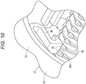
- the pressing protrusion 30 when the plunger 20 rotates in the forward direction, the plurality of pressing protrusions 30 presses the displacement mechanism part 40. Therefore, at the time of forward rotation of the plunger 20, the pressing protrusion 30 can be made to reliably abut on the displacement mechanism part 40. In addition, when the pressed part 40b is pressed, the load applied to each pressing protrusion 30 decreases, and breakage of the pressing protrusion 30 can be prevented.
- the grip 22 includes an internal space 70 (see FIG. 4 ) in which the displacement mechanism part 40 is disposed to echo the sound generated with collision of the displacement mechanism part 40 against the wall 63. Therefore, it is possible to amplify a sound pressure level of the click sound generated by the collision of the displacement mechanism part 40 against the wall 63 in the internal space 70, and to provide the user with a clear click sound.
- the plunger 20 and the pressing part 28 are rotatable relative to each other, and the frictional resistance between the gasket 16 and the pressing part 28 is larger than the frictional resistance between the pressing part 28 and the plunger rod 24. Therefore, as illustrated in FIG. 8 , when the gasket 16 is pressed with the rotation of the plunger 20, the gasket 16 advances without rotating inside the barrel 14. Therefore, deformation of the gasket 16 can be suppressed, and the liquid-tightness between the inner surface of the barrel 14 and the gasket 16 can be favorably secured.
- the pressure inside the barrel 14 can be immediately released, and the discharge of the drug solution M can be quickly stopped. That is, when the plunger 20 is rotated in the reverse direction from the state in which the plunger 20 is rotated in the forward direction to discharge the drug solution M in the barrel 14, the plunger 20 retracts with respect to the barrel 14. At this time, since the gasket 16 retracts by the pressure of the drug solution M increased at the time of the forward rotation of the plunger 20, the pressurization in the barrel 14 is released and the discharge of the drug solution M is stopped.
- the drug solution M has a viscosity in a range of 50 to 120 mPa ⁇ s. Since the drug solution M has such a viscosity, the pressure of the drug solution M increased at the time of the forward rotation of the plunger 20 is maintained until immediately before the reverse rotation. Therefore, at the time of reverse rotation, the gasket 16 is reliably retracted in the proximal end direction by the pressure of the drug solution M, and the pressurization is released.
- the displacement mechanism part 40 is displaced radially outward of the plunger 20 and gets on the pressing protrusion 30. That is, since the reverse rotation of the plunger 20 is not inhibited by the pressing protrusion 30 (the plunger 20 idles in relation to the pressing protrusion 30), the plunger 20 is rotated in the reverse direction to release the pressure inside the syringe 12, and the discharge of the drug solution M can be stopped. Further, when the plunger 20 rotates in the reverse direction, since the displacement mechanism part 40 does not collide against the wall 63, the plunger 20 can idle without generating a clear sound like a click sound.
- the displacement mechanism part 40 gets on the pressing protrusion 30, while being elastically deformed. Since the curved part 30b is disposed at the pressing protrusion 30 and the tapered part 40d is disposed at the displacement mechanism part 40, the pressing protrusion 30 smoothly gets on. Further, as illustrated in FIG. 11B , when the pressing protrusion 30 further displaces in the circumferential direction with the reverse rotation of the plunger 20, the displacement mechanism part 40 falls (comes off) from the pressing protrusion 30, and returns to the original shape (displaces to the plunger 20 side) by the elastic restoring force.
- the elastic piece part 40a extends from the support part (the fixing base part 66) along the direction in which the pressed part 40b is pressed and displaced at the time of the forward rotation of the plunger rod 24. Therefore, when the plunger 20 rotates in the reverse direction, the displacement mechanism part 40 is easily deformed radially outward of the plunger 20 along the wall 63. Therefore, the plunger 20 can be rotated in the reverse direction without applying a large torque.
- the rotary operation part 26 includes a finger hook rotary operation part 26a protruding in a direction perpendicular to the axis of the plunger rod 24, and a pinch rotary operation part 26b protruding in the proximal end direction from the finger hook rotary operation part 26a coaxially with the plunger rod 24.
- the screw thread 25 can be screwed with a female screwing part 46 disposed in the syringe 12 or attached to the syringe 12, and the plunger 20 can be advanced in the distal end direction by the screwing action between the screw thread 25 and the female screwing part 46 to press the gasket 16 in the distal end direction.
- the outer diameter of the pinch rotary operation part 26b is smaller than the outer diameter of the finger hook rotary operation part 26a. Therefore, when it is not necessary to apply a large torque to the plunger 20, by operating the pinch rotary operation part 26b, the plunger 20 can be rotated quickly and the plunger 20 can be advanced quickly. Therefore, the treatment using the syringe 12 can be efficiently performed. That is, depending on the situations, it is possible to select to apply a large torque to the syringe plunger by operating the finger hook rotary operation part 26a and to quickly rotate and advance the syringe plunger by operating the pinch rotary operation part 26b.
- the finger hook rotary operation part 26a protrudes rather than the screw thread 25 in a direction perpendicular to the axis of the plunger rod 24. Therefore, a larger torque can be applied to the plunger 20.
- the outer diameter of the pinch rotary operation part 26b is smaller than the outer diameter of the screw thread 25.
- the pinch rotary operation part 26b includes a cylindrical shape. Therefore, when the pinch rotary operation part 26b is operated by being pinched, the plunger 20 can be easily and more quickly rotated.
- an anti-slip structure for the finger is disposed at the outer circumferential portion of the pinch rotary operation part 26b, when the pinch rotary operation part 26b is operated by being pinched, slippage of the finger is suppressed and the operation is easily performed.
- the finger hook rotary operation part 26a includes a pair of rod-like finger hook parts 27 protruding in opposite directions to each other from the plunger rod 24. For this reason, it is easy to apply a large torque to the plunger 20 when operating the finger hook rotary operation part 26a by hooking a finger.
- a constricted part 27a and a bulging part 27b disposed outside the constricted part 27a are disposed in the pair of rod-like finger hook parts 27, when operating the finger hook rotary operation part 26a by hooking a finger, the user can easily hook his/her finger.
- ESD endoscopic submucosal dissection
- EMR endoscopic mucosal resection
- the user attaches the pressurization device 10 to the syringe 12 (pre-filled syringe) filled with the sodium hyaluronate solution M1 and detaches the cap 18 from the syringe 12.
- the user connects the distal end portion (the nozzle 14b) of the syringe 12 to the proximal end portion of the inner catheter 82 of the puncturing device 80, and in the state of causing the needle 82a to protrude from the outer catheter 84, the plunger 20 is advanced by being rotated, and priming (filling the lumen of the inner catheter 82 and the needle 82a with the sodium hyaluronate solution M1) is performed.
- the user may rotate the plunger 20 by picking the pinch rotary operation part 26b illustrated in FIG. 1 or the like with a finger.
- the plunger 20 can be quickly rotated and the plunger 20 can be advanced quickly.
- the puncturing device 80 includes an inner catheter 82 and an outer catheter 84.
- the inner catheter 82 is axially slidable with respect to the outer catheter 84 within a restricted range.
- the needle 82a is connected to the distal end of the inner catheter 82.
- the needle 82a is accommodated within the outer catheter 84.
- the needle 82a protrudes from the distal end of the outer catheter 84.
- the user retracts the inner catheter 82 to accommodate the needle 82a in the outer catheter 84. Further, the user inserts the puncturing device 80 into the insertion hole 86a (see FIG. 13A ) of the endoscope 86.
- the user who is a surgeon causes the needle 82a to protrude from the distal end of the endoscope 86 in the digestive tract of the patient as illustrated in FIG. 13A . Further, the user approaches the mucous membrane 90 around the lesioned part 88, and advances the needle 82a toward the mucous membrane 90. As a result, the needle 82a penetrates the mucous membrane 90 and is punctured into a submucosal layer 91.
- a predetermined amount of sodium hyaluronate solution M1 is injected into the submucosal layer 91 to raise the lesioned part 88.
- the hyaluronate solution M1 in the syringe 12 is pressurized by the pressurization device 10 (the plunger 20 is rotated in the forward direction to advance the gasket 16)
- the sodium hyaluronate solution M1 is injected into the submucosal layer 91 from the distal end opening of the needle 82a.
- the lesioned part 88 is lifted by injection of sodium hyaluronate solution M1. That is, the submucosal layer 91 under the lesioned part 88 is peeled off from the muscular layer 92 and the lesioned part 88 is raised.
- the syringe 12 has a moderate length (a length not too long) which is easy to handle, and the syringe 12 is filled with the sodium hyaluronate solution M1 in an amount sufficient to raise the lesioned part 88 by a single injection. Therefore, the inner diameter of the barrel 14 also has a size corresponding to such an amount. Therefore, in order to inject the sodium hyaluronate solution M1 having a relatively high viscosity via the needle 82a, it is necessary to press the gasket 16 in the distal end direction with a large force. In the present embodiment, since the pressurization device 10 is used, it is possible to advance the gasket 16 and inject the sodium hyaluronate solution M1 via the needle 82a without requiring an excessive operating force in the operation of the plunger 20.
- the user rotates the plunger 20 in the reverse direction to release the pressurization.
- the discharge of the sodium hyaluronate solution M1 from the syringe 12 stops immediately, and the injection amount of the sodium hyaluronate solution M1 into the submucosal layer 91 can be accurately controlled.
- the user inserts a peeling device 94 (an acicular scalpel or the like) into a forceps hole 86b of the endoscope 86, and cuts the mucous membrane 90 to surround the lesioned part 88, using the peeling device 94.
- a gripping device 96 into the forceps hole 86b of the endoscope 86, peels off the mucous membrane 90 having the lesioned part 88, using the gripping device 96, and extracts the peeled mucous membrane 90 to the outside of the body.
- an ablation device 98 indicated by an imaginary line in FIG. 13C is used instead of the peeling of the mucous membrane 90 by the peeling device 94 described above.
- the ablation device 98 includes a snare ring 98a (a loop-shaped electric scalpel). The user causes the snare ring 98a to protrude from the endoscope 86 in the patient's body and hooks the snare ring 98a to the mucous membrane 90 around the raised lesioned part 88.
- the mucous membrane 90 having the lesioned part 88 is cut.
- the cut mucous membrane 90 is collected by the gripping device 96 illustrated in FIG. 13D .
- Other procedure processes are performed in the same manner as the above-described endoscopic submucosal dissection.
Landscapes
- Health & Medical Sciences (AREA)
- Vascular Medicine (AREA)
- Engineering & Computer Science (AREA)
- Anesthesiology (AREA)
- Biomedical Technology (AREA)
- Heart & Thoracic Surgery (AREA)
- Hematology (AREA)
- Life Sciences & Earth Sciences (AREA)
- Animal Behavior & Ethology (AREA)
- General Health & Medical Sciences (AREA)
- Public Health (AREA)
- Veterinary Medicine (AREA)
- Infusion, Injection, And Reservoir Apparatuses (AREA)
Abstract
Description
- The present invention relates to a syringe plunger, a syringe pressurization device, and a syringe system to be attached to a syringe having a barrel and a gasket sliding inside the barrel.
- In related art, a so-called threaded syringe configured to advance a plunger by a screwing action of a screw in order to discharge a drug solution having a relatively high viscosity from a syringe barrel has been known (for example, see
JP 2005-535415 A JP 2005-535415 A - In
JP 2005-535415 A - The present invention has been made in view of such problems, and an object of the present invention is to provide a syringe plunger and a syringe system capable of selecting application of a large torque to the syringe plunger and quick rotation and advancement of the syringe plunger, depending on the situation.
- To achieve the aforementioned object, the present invention provides a syringe plunger configured to be attached to a syringe having a barrel and a gasket sliding inside the barrel, the syringe plunger including a plunger rod including a screw thread disposed on an outer circumferential surface thereof; and a rotary operation part disposed at a proximal end portion of the plunger rod, in which the rotary operation part includes a finger hook rotary operation part protruding in a direction perpendicular to an axis of the plunger rod, and a pinch rotary operation part protruding in a proximal end direction from the finger hook rotary operation part coaxially with the plunger rod. The screw thread is configured to be screwed with a female screwing part disposed in the syringe or attached to the syringe, the syringe plunger is configured to advance in a distal end direction by a screwing action between the screw thread and the female screwing part so as to press the gasket in a distal end direction, and an outer diameter of the pinch rotary operation part is smaller than an outer diameter of the finger hook rotary operation part.
- According to the syringe plunger of the present invention having the above configuration, when it is not necessary to apply a large torque to the plunger, by operating the pinch rotary operation part, the plunger can be rotated quickly and the plunger can be advanced quickly. Therefore, the treatment using the syringe can be efficiently performed.
- In the aforementioned syringe plunger, the finger hook rotary operation part may protrude rather than the screw thread in a direction perpendicular to the axis of the plunger rod.
- With this configuration, a larger torque can be applied to the syringe plunger.
- In the aforementioned syringe plunger, the outer diameter of the pinch rotary operation part may be smaller than the outer diameter of the screw thread.
- With this configuration, it is easy to rotate the plunger more quickly when pinching and operating the pinch rotary operation part.
- In the aforementioned syringe plunger, the pinch rotary operation part may have a cylindrical shape.
- With this configuration, it is easy to rotate the plunger more quickly when pinching and operating the pinch rotary operation part.
- In the aforementioned syringe plunger, an anti-slip structure for a finger may be disposed on an outer circumferential portion of the pinch rotary operation part.
- With this configuration, slippage of the finger is suppressed when the pinch rotary operation part is operated by being pinched and the operation is easily performed.
- In the aforementioned syringe plunger, the finger hook rotary operation part may have a pair of rod-like finger hook parts protruding in directions opposite to each other from the plunger rod.
- With this configuration, it is easy to apply a large torque to the syringe plunger when operating the finger hook rotary operation part by hooking a finger.
- In the syringe plunger, a constricted part, and a bulging part disposed outside the constricted part may be disposed in the pair of rod-like finger hook parts.
- With this configuration, when operating the finger hook rotary operation part by hooking a finger, the user can easily hook his/her fingers.
- Further, a syringe system of the present invention includes the aforementioned syringe plunger, the syringe in which the female screwing part is disposed or to which the female screwing part is attached, and a drug solution filled in a liquid chamber formed by the barrel and the gasket of the syringe.
- According to the present invention, depending on the situation, it is possible to choose to apply a large torque to the syringe plunger and to quickly rotate and advance the syringe plunger.
- Further, the present invention also provides a syringe pressurization device attached to a syringe having a barrel and a gasket sliding inside the barrel, the syringe pressurization device including: a plunger configured to press the gasket in a distal end direction by forward movement in a distal end direction and including a plunger rod including a screw thread disposed on an outer circumferential surface; and a grip attachable to the barrel and supporting the plunger, in which the plunger includes a pressing protrusion protruding outward from the screw thread disposed in the plunger rod, the grip includes a female screwing part configured to be screwed to the screw thread, a displacement mechanism part having an elastic force and being displaceable against the elastic force by being pressed by the pressing protrusion, and a wall with which the displacement mechanism part is configured to collide. The plunger is movable in an axial direction with rotation of the plunger rod by screwing between the screw thread and the female screwing part. During a forward rotation of the plunger rod (24) for advancing the plunger, the displacement mechanism part is displaced against the elastic force by being pressed by the pressing protrusion displaced in a forward rotation direction of the plunger rod, and is repelled with passage of the pressing protrusion so as to collide against the wall.
- According to the syringe pressurization device of the present invention having the above-mentioned configuration, when rotated in the forward direction for advancement of the plunger, the displacement mechanism part disposed in the grip is repelled by the pressing protrusion disposed on the screw thread of the plunger. Further, the displacement mechanism part repelled by the pressing protrusion is displaced by the elastic restoring force and collides against the wall disposed on the grip. Therefore, a click sound having a constant magnitude can be generated, irrespective of the rotational speed of the plunger. Thus, even when the plunger is slowly rotated, the click sound can be reliably generated.
- In the aforementioned syringe pressurization device, the displacement mechanism part may be displaced substantially along a direction of the tangential force acting on the pressing protrusion which starts to press the displacement mechanism part at the time of the forward rotation of the plunger rod.
- With this configuration, since the force received by the displacement mechanism part from the pressing protrusion increases, and the displacement amount of the displacement mechanism part also increases, a larger click sound can be generated.
- In the aforementioned syringe pressurization device, the grip may have a support part supporting the displacement mechanism part, and the displacement mechanism part may have an elastic piece part extending from the support part.
- Thus, elastic energy can be accumulated when pressed by the pressing protrusion with a simple structure.
- In the aforementioned syringe pressurization device, the elastic piece part may have a U-shaped curved part which opens in a direction substantially opposite to a direction of a tangential force acting on the pressing protrusion which starts to press the displacement mechanism part at the time of the forward rotation of the plunger rod.
- Since this makes it easy to balance well the easiness of deformation of the displacement mechanism part and the strength of the elastic restoring force, it is possible to generate a clear click sound, while suppressing an increase in the rotation resistance of the plunger.
- In the aforementioned syringe pressurization device, the grip may have an internal space in which the displacement mechanism part is disposed and that echoes a sound generated with collision of the displacement mechanism part to the wall.
- Therefore, it is possible to amplify a sound pressure level of the click sound generated by the collision of the displacement mechanism part to the wall in the space, and to provide the user with a clear click sound.
- In the aforementioned syringe pressurization device, a pressed part to be pressed by the pressing protrusion at the time of the forward rotation of the plunger rod may be disposed on the displacement mechanism part, and a rod position restricting part configured to restrict a position of the plunger rod with respect to the pressed part on a side opposite to the pressed part on the basis of the plunger rod may be disposed at the grip.
- With this configuration, when the plunger rod rotates, it is possible to reliably press the pressed part in the circumferential direction by the pressing protrusion.
- In the aforementioned syringe pressurization device, at the time of a reverse rotation of the plunger for a backward movement in a proximal end direction, the displacement mechanism part may be pressed by the pressing protrusion so as climb over the pressing protrusion with a displacement in a direction different from the displacement direction of the displacement mechanism part at the time of the forward rotation of the plunger.
- With this configuration, since the reverse rotation of the plunger is not inhibited by the pressing protrusion (the plunger idles in relation to the pressing protrusion), the plunger is rotated in the reverse direction to release the pressure inside the syringe, and the discharge of the drug solution can be stopped. Further, when the plunger rotates in the reverse direction, since the displacement mechanism part does not collide against the wall, the plunger can be idly rotated without generating a clear sound like a click sound.
- In the aforementioned syringe pressurization device, the grip may have a support part supporting the displacement mechanism part, the displacement mechanism part may have an elastic piece part extending from the support part, and a pressed part pressed by the pressing protrusion at the time of the forward rotation of the plunger rod, and the elastic piece part may extend from the support part along a direction in which the pressed part is pressed and displaced at the time of the forward rotation of the plunger rod.
- With this configuration, at the time of reverse rotation of the plunger, the displacement mechanism part is likely to deform radially outward of the plunger along the wall. Therefore, the plunger can be rotated in the reverse direction without applying a large torque.
- In the aforementioned syringe pressurization device, the elastic piece part may have a first extending part extending from the support part along a direction in which the pressed part is pressed and displaced at the time of the forward rotation of the plunger rod, a curved extending part extending from an extending distal end of the first extending part with being curved in a direction opposite to the extending direction of the first extending part, and a second extending part extending from the extending distal end of the curved extending part in the direction opposite to the extending direction of the first extending part, and the pressed part may be disposed at the extending distal end of the second extending part.
- Further, a syringe system of the present invention includes the aforementioned syringe pressurization device, the syringe, and a drug solution filled in a liquid chamber formed by the barrel and the gasket of the syringe.
- Further, the present invention also provides a syringe pressurization device attached to a syringe having a barrel and a gasket sliding inside the barrel, the syringe pressurization device including: a plunger configured to advance the gasket in a distal end direction; and a grip attachable to the barrel from a direction perpendicular to an axis of the barrel and supporting the plunger, in which the plunger includes a plunger rod including a screw thread disposed on an outer circumferential surface thereof, and a pressing part disposed at a distal end of the plunger rod and configured to press the gasket in a distal end direction, the grip includes a flange attachment part attachable to a flange disposed at a proximal end portion of the barrel, a female screwing part disposed on proximal of the flange attachment part and screwed to the screw thread, and an accommodation part disposed between the flange attachment part and the female screwing part and configured to accommodate the pressing part.
- According to the syringe pressurization device of the present invention having the aforementioned configuration, the accommodation part capable of accommodating the pressing part of the plunger is disposed between the flange attachment part and the female screwing part of the grip. Therefore, the syringe pressurization device in a state in which the grip and the plunger are assembled can be attached to the barrel from a direction perpendicular to the axis of the barrel. Therefore, one-touch attachment of the syringe pressurization device to the syringe is possible.
- In the aforementioned syringe pressurization device, the plunger rod may have a rotation support part at a distal end portion thereof, the pressing part is a disc-shaped member supported on the rotation support part of the plunger rod to be rotatable about the axis of the plunger rod and having a larger diameter than that of the plunger rod, and the accommodation part is a circular groove recessed in the proximal end direction with respect to the flange attachment part and having an inner diameter larger than an outer diameter of the pressing part.
- According to this configuration, it is possible to secure liquid-tightness between the inner surface of the barrel and the gasket by preventing rotation of the gasket with rotation of the plunger, while realizing one-touch attachment by disposing the accommodation part.
- In the aforementioned syringe pressurization device, the rotation support part may have a locking claw protruding outward at a distal end thereof, the pressing part may have a tubular base part constituting a center side thereof, and a ring-shaped abutting part extending outward from the tubular base part and configured to abut on the proximal end surface of the gasket, a ring-shaped locking protrusion protruding inward may be disposed on an inner circumferential surface of the tubular base part, and the pressing part may be prevented from slipping out from the rotation support part in the distal end direction, by the locking claw and the ring-shaped locking protrusion.
- According to this configuration, the rotatably coupled state between the pressing part and the plunger rod is satisfactorily maintained.
- In the aforementioned syringe pressurization device, in a state in which the pressing part is accommodated deepest with respect to the accommodation part, a distal end surface of the pressing part may be located at the proximal end side of the most distal end position of the accommodation part.
- According to this configuration, when the syringe pressurization device is attached to the barrel, it is possible to reliably prevent the pressing part from being caught by the proximal end portion of the barrel.
- Further, a syringe system according to the present invention includes a prefilled syringe including a barrel, a gasket disposed to be slidable in the barrel, and a drug solution filled in a liquid chamber formed by the barrel and the gasket, and a syringe pressurization device attachable to the prefilled syringe, in which the syringe pressurization device is the syringe pressurization device according to one of the aforementioned aspects.
- Thus, the syringe pressurization device that can be attached with one touch is particularly useful when applied to a pre-filled syringe.
- In the aforementioned syringe system, the pressing part may be rotatable about an axis of the plunger rod with respect to the plunger rod, and frictional resistance between the pressing part and the gasket generated when the pressing part rotates about the axis of the plunger rod with respect to the gasket may be greater than frictional resistance between the pressing part and the plunger rod generated when the pressing part rotates about the axis of the plunger rod with respect to the plunger rod.
- According to this configuration, when the gasket is pressed with the rotation of the plunger, the gasket advances without rotating inside the barrel. Therefore, deformation of the gasket can be suppressed, and the liquid-tightness between the inner surface of the barrel and the gasket can be favorably secured.
-
-
FIG. 1 is a perspective view of a syringe system including a syringe and a syringe pressurization device; -
FIG. 2 is an exploded perspective view of the syringe pressurization device; -
FIG. 3 is a cross-sectional view along an axis of the syringe pressurization device; -
FIG. 4 is a cross-sectional view perpendicular to the axis of the syringe pressurization device; -
FIG. 5 is a cross-sectional view of a main part of the syringe pressurization device; -
FIG. 6 is a perspective cross-sectional view from a proximal end side of a first member; -
FIG. 7 is a perspective view of an assembled state of the syringe and the syringe pressurization device; -
FIG. 8 is a cross-sectional view of a state in which a gasket is advanced by a plunger; -
FIG. 9A is an explanatory view of a state in which a pressing protrusion of the plunger that rotates in a forward direction moves a displacement mechanism part of a grip, andFIG. 9B is an explanatory view of a state in which the displacement mechanism part repelled by the pressing protrusion collides against a wall of the grip; -
FIG. 10 is an explanatory view of a state in which the two pressing protrusions of the plunger abut on the displacement mechanism part of the grip; -
FIG. 11A is an explanatory view of a state in which the displacement mechanism part gets on the pressing protrusion of the plunger that rotates in a reverse direction, andFIG. 11B is an explanatory view of a state in which the displacement mechanism part is disengaged from the pressing protrusion of the plunger that rotates in the reverse direction; -
FIG. 12 is an explanatory view of a state in which the syringe is connected to a proximal end portion of a puncturing device and a needle disposed at a distal end portion of an inner catheter of the puncturing device is caused to protrude from the distal end of an outer catheter; and -
FIG. 13A is an explanatory view of a process of causing the needle of the puncturing device to protrude from a distal end of an endoscope in a living body,FIG. 13B is an explanatory view of a process of injecting hyaluronic acid into a tissue under the lesioned part to raise the lesioned part,FIG. 13C is an explanatory view of a process of cutting a mucous membrane around the lesioned part by a peeling device, andFIG. 13D is an explanatory view of a process of collecting the mucous membrane having the lesioned part by a gripping device. - Preferred embodiments of the present invention will be described below with reference to the accompanying drawings.
- A syringe pressurization device 10 (hereinafter abbreviated as a "
pressurization device 10") illustrated inFIG. 1 is a device which is attached to asyringe 12 and is used for discharging a drug solution M in thesyringe 12 by pressing agasket 16 of thesyringe 12 in a distal end direction. Thesyringe system 11 is constituted by thesyringe 12 and thepressurization device 10. - In
FIG. 1 , thesyringe 12 includes a hollowtubular barrel 14, a gasket 16 (also referred to as a stopper) disposed inside thebarrel 14 to be axially slidable in a liquid-tight manner, and the drug solution M filled in a liquid chamber formed by thebarrel 14 and thegasket 16. That is, thesyringe 12 is configured as a prefilled syringe in which the drug solution M is prefilled in thebarrel 14. - The drug solution M has a relatively high viscosity such that the
pressurization device 10 is required for discharging from thesyringe 12, and for example, a sodium hyaluronate solution can be used. The viscosity of the drug solution M is, for example, in a range of 50 to 120 mPa·s. - The
barrel 14 includes abarrel body portion 14a having a substantially tubular shape and having a proximal end opening portion formed at a proximal end thereof, anozzle 14b (see alsoFIG. 7 ) disposed at the distal end of thebarrel body portion 14a, alock adapter 14c disposed on the outer side of thenozzle 14b, and aflange 14d protruding radially outward from the proximal end of thebarrel body portion 14a. - The
barrel 14 is set to have a capacity capable of injecting a relatively large amount of drug solution M by a single injection operation. The capacity of thebarrel 14 is, for example, in a range of 5 to 100 mL. Therefore, an outer diameter of thebarrel body portion 14a is set to a relatively large diameter, for example, in a range of 14 to 36 mm. - The
nozzle 14b is reduced in diameter from the center of the distal end of thebarrel body portion 14a with respect to thebarrel body portion 14a and extends in the distal end direction. Thenozzle 14b is configured as a male luer which includes a circular cross-sectional outer shape and includes a tapered outer circumferential surface with an outer diameter reduced in the distal end direction. Thenozzle 14b can be fitted to another device having a female luer (for example, apuncturing device 80 to be described below). - In an initial state of the
syringe 12 illustrated inFIG. 1 , acap 18 is attached to thenozzle 14b, and the distal end opening portion of thenozzle 14b is liquid-tightly sealed by thecap 18. Thecap 18 is detached from thenozzle 14b when thesyringe 12 is used. An outer circumferential portion of thegasket 16 comes into contact with an inner circumferential surface of thebarrel body portion 14a in a liquid tight manner, and thegasket 16 is disposed to be slidable in thebarrel body portion 14a. - The
pressurization device 10 includes a syringe plunger 20 (hereinafter, abbreviated as a "plunger 20") capable of pressing thegasket 16 in the distal end direction, and agrip 22 that can be attached to thebarrel 14 and supports theplunger 20. Theplunger 20 is displaced in an axial direction with respect to thegrip 22 with rotation by the screwing action of the screw. Theplunger 20 advances with respect to thegrip 22 by a forward rotation and retracts with respect to thegrip 22 by a reverse rotation. - As illustrated in
FIG. 2 , theplunger 20 includes aplunger rod 24 having ascrew thread 25 on its outer circumferential surface, arotary operation part 26 disposed at the proximal end portion of theplunger rod 24, and apressing part 28 disposed at the distal end portion of theplunger 20. Theplunger rod 24 includes ashaft part 24a which is a rod main body, and thescrew thread 25 is formed on the outer circumferential surface of theshaft part 24a. Thescrew thread 25 extends spirally in a range from the proximal end portion of theshaft part 24a to the vicinity of the distal end portion. - On the top of the
screw thread 25, apressing protrusion 30 protruding outward (radially outward) from thescrew thread 25 is disposed. In theplunger 20, a plurality of pressingprotrusions 30 is disposed. Specifically, a large number ofpressing protrusions 30 is disposed at equal angle intervals (90° intervals in the illustrated example) on thescrew thread 25 extending in a spiral shape. In this embodiment, aprotrusion row 32 is constituted by the plurality of pressingprotrusions 30 arranged on the same straight line parallel to the axis of theplunger rod 24, and a plurality ofprotrusion rows 32 is disposed at equal intervals in the circumferential direction. - In
FIG. 1 , when theplunger 20 is advanced, theplunger 20 is rotated in the forward rotation direction indicated by a direction of an arrow R1, and when theplunger 20 is retracted, theplunger 20 is rotated in the reverse rotation direction indicated by a direction of an arrow R2. As illustrated inFIG. 5 , anengaging part 30a substantially perpendicular to the circumferential direction of theplunger 20 is disposed on the side of thepressing protrusion 30 in the forward rotation direction (the direction of the arrow R1). On the other hand, acurved part 30b formed in an arc shape is disposed on the side of thepressing protrusion 30 in the reverse rotation direction (the direction of the arrow R2). - In
FIGS. 1 and2 , therotary operation part 26 is a part which is grabbed by a user's finger for operation in order to rotate theplunger 20. Therotary operation part 26 is disposed so as not to be rotatable with respect to theplunger rod 24. In this embodiment, therotary operation part 26 is formed integrally with theplunger rod 24. - The
rotary operation part 26 includes a finger hookrotary operation part 26a and a pinchrotary operation part 26b. The finger hookrotary operation part 26a protrudes in a direction perpendicular to the axis of theplunger rod 24. The finger hookrotary operation part 26a protrudes outward in the radial direction from theplunger rod 24 and the pinchrotary operation part 26b. - In the present embodiment, the finger hook
rotary operation part 26a includes a pair of rod-likefinger hook parts 27 protruding in directions opposite to each other from theplunger rod 24. Aconstricted part 27a having a relatively small width and abulging part 27b having a relatively large width disposed outside theconstricted part 27a are disposed at the rod-likefinger hook part 27. A step difference between theconstricted part 27a and the bulgingpart 27b makes it easier for the user to hook a finger. - The pinch
rotary operation part 26b protrudes from the finger hookrotary operation part 26a in the proximal end direction coaxially with theplunger rod 24. The pinchrotary operation part 26b is formed in a substantially tubular shape. The pinchrotary operation part 26b is formed to have an appropriately small diameter so that theplunger 20 can be quickly rotated by the user's fingers in a case in which a large torque is not required when theplunger 20 is rotated. The outer diameter of the pinchrotary operation part 26b is, for example, in a range of 3 to 15 mm, preferably in a range of 7 to 10 mm. In the present embodiment, the outer diameter of the pinchrotary operation part 26b is smaller than the outer diameter of thescrew thread 25. - In order to prevent easy slip of the finger when the user pinches the pinch
rotary operation part 26b with the finger to rotate, a plurality ofnarrow grooves 26c extending along the axis of theplunger 20 is formed as an anti-slip structure on the outer circumferential surface of the pinchrotary operation part 26b at intervals in the circumferential direction. Knurling may be disposed in place of the plurality ofnarrow grooves 26c. - In
FIG. 2 , thepressing part 28 is a disk-shaped member that is rotatably supported by the distal end portion of theplunger rod 24 and has a larger diameter than that of theplunger rod 24. As illustrated inFIG. 3 , arotation support part 34 that rotatably supports thepressing part 28 is disposed at the distal end portion of the plunger rod 24 (theshaft part 24a) . A lockingclaw 34a protruding outward is disposed at the distal end of therotation support part 34. - The
pressing part 28 includes atubular base part 28a constituting a center side, and a ring-shapedabutting part 28b extending outward from thetubular base part 28a. On the inner circumferential surface of thetubular base part 28a, a ring-shapedlocking protrusion 28c protruding inward is disposed. The lockingclaw 34a and the ring-shapedlocking protrusion 28c constitute a stopper means for preventing thepressing part 28 from being slipped off from therotation support part 34 in the distal end direction. - As illustrated in
FIG. 8 , theabutting part 28b is a portion that abuts on theproximal end surface 16a of thegasket 16 when thegasket 16 is pressed. The distal end surface of theabutting part 28b is formed in a flat shape perpendicular to the axis of theplunger 20. The outer diameter of theabutting part 28b is preferably set to be the same as the outer diameter of theproximal end surface 16a of thegasket 16, or is equal to or smaller than the outer diameter of theproximal end surface 16a of thegasket 16 and is close to the outer diameter. In the present embodiment, the outer diameter of theabutting part 28b is set to be approximately the same as the outer diameter of theproximal end surface 16a of thegasket 16. - In
FIG. 1 , thegrip 22 is configured to be attachable to thebarrel 14 from a direction perpendicular to the axis of thebarrel 14. As illustrated inFIG. 2 , thegrip 22 includes afirst member 36 constituting a grip main body portion, and asecond member 38 fixed to thefirst member 36 and provided with adisplacement mechanism part 40. - As illustrated in
FIG. 3 , thefirst member 36 includes abarrel attachment part 42 attachable to the outer circumferential surface of thebarrel 14, aflange attachment part 44 attachable to theflange 14d, afemale screwing part 46 screwed to thescrew thread 25 of theplunger 20, and anaccommodation part 48 formed between theflange attachment part 44 and thefemale screwing part 46. - The
barrel attachment part 42 and theflange attachment part 44 are formed with attachment openings 50 (see alsoFIG. 2 ) in which thebarrel attachment part 42 and theflange attachment part 44 are cut in the axial direction. Thebarrel attachment part 42 extends in the axial direction by a predetermined length, is curved along the outer circumferential surface of thebarrel 14, and is formed in a C-shaped cross section. - The
flange attachment part 44 includes a distal endside holding part 52, a proximal endside holding part 54, and a connectingpart 56 which connects the distal endside holding part 52 and the proximal endside holding part 54. A holdinggroove 58 is formed between the distal endside holding part 52 and the proximal endside holding part 54. As illustrated inFIG. 8 , in a state in which thegrip 22 is attached to thebarrel 14, theflange 14d is inserted into the holdinggroove 58, and theflange 14d is sandwiched and held between the holdingsurfaces grip 22 in the axial direction with respect to thebarrel 14 is restricted. - As illustrated in
FIG. 3 , in thefirst member 36, an accommodationpart forming part 60 is disposed to be adjacent to the proximal end side of theflange attachment part 44, a first tubular part 62 (see alsoFIG. 2 ) is disposed to be adjacent to the proximal end side of the accommodationpart forming part 60, and a second tubular part 64 (see alsoFIG. 2 ) is disposed to be adjacent to the proximal end side of the firsttubular part 62. Theaccommodation part 48 capable of accommodating the aforementioned pressingpart 28 of theplunger 20 is formed inside the accommodationpart forming part 60. As illustrated inFIG. 6 , theaccommodation part 48 is a circular groove which is recessed in the proximal end direction with respect to the flange attachment part 44 (specifically, the holdingsurface 54a of the proximal end side holding part 54) and has an inner diameter larger than the outer diameter of thepressing part 28. - As illustrated in
FIGS. 4 and6 , ahole part 62a penetrating a circumferential wall of the firsttubular part 62 in the thickness direction is disposed in the firsttubular part 62. Thedisplacement mechanism part 40 of thesecond member 38 is inserted into thehole part 62a. Awall 63 is disposed in the firsttubular part 62 to be adjacent to thehole part 62a. Thewall 63 protrudes outward from the outer circumferential surface of the firsttubular part 62. A pair of fixingribs 62b protrudes from the outer circumferential surface of the firsttubular part 62 in the directions opposite to each other. Thewall 63 is disposed at a substantially central position between the pair of fixingribs 62b in the circumferential direction of the firsttubular part 62. - As illustrated in
FIG. 4 , a rodposition restricting part 62c which restricts the position of theplunger rod 24 with respect to thepressed part 40b is disposed on the side opposite to thepressed part 40b on the basis of theplunger rod 24. The rodposition restricting part 62c is a portion padded on an arcuate inner circumferential surface of the firsttubular part 62. When coming into contact with thepressing protrusion 30, the rodposition restricting part 62c restricts the position of theplunger rod 24 so that thepressing protrusion 30 on the opposite side thereof can press thedisplacement mechanism part 40. - As illustrated in
FIG. 3 , afemale screwing part 46 is formed on the inner circumferential surface of the secondtubular part 64. Thefemale screwing part 46 includes ascrew thread 46a extending in a spiral shape. Agroove 46b between thescrew threads 46a adjacent to each other in the axial direction has a depth that permits thepressing protrusion 30 of theplunger 20 to enter. As thefemale screwing part 46, instead of thescrew thread 46a extending in a spiral shape, a protruding part to be screwed to thescrew thread 25 as the male screwing part of theplunger 20 may be disposed. - As illustrated in
FIGS. 2 and4 , thesecond member 38 includes a fixingbase part 66 which is fixed to thefirst member 36 and supports thedisplacement mechanism part 40. Thedisplacement mechanism part 40 extends from the inner surface of the fixingbase part 66. The fixingbase part 66 is formed in a C shape to partially surround the firsttubular part 62 of thefirst member 36. - As illustrated in
FIG. 4 , a pair offitting grooves 66b is disposed on the inner surfaces of the mutually facingside walls 66a of the fixingbase part 66. A pair of fixingribs 62b of thefirst member 36 is fitted to the pair offitting grooves 66b, respectively. Therefore, thesecond member 38 is positioned with respect to thefirst member 36 in a direction perpendicular to the axis of thefirst member 36. - A pair of engaging
claws 66c is disposed at both circumferential end portions of the fixingbase part 66. Specifically, the pair of engagingclaws 66c is formed at the end portions of a pair ofarms 66d which is curved from theside walls 66a on both sides and extends inward. The pair of engagingclaws 66c is engaged with an engagingprotrusion 62d disposed on the first member 36 (specifically, the first tubular part 62). Thus, the fixing of thesecond member 38 to thefirst member 36 becomes more rigid. Further, the engagingclaw 66c and the engagingprotrusion 62d may not be disposed. - As illustrated in
FIG. 3 , thesecond member 38 is held between a proximal endside holding part 54 and a flange-like wall part 65 protruding outward from the outer circumferential surface of the secondtubular part 64. As a result, thesecond member 38 is positioned with respect to thefirst member 36 in the axial direction of thefirst member 36. Aninternal space 70 surrounded by thefirst member 36 and thesecond member 38 is formed inside thesecond member 38, and thedisplacement mechanism part 40 is disposed in theinternal space 70. - As illustrated in
FIG. 4 , thedisplacement mechanism part 40 extends from a dome-shapedintermediate wall part 66e that connects theside walls 66a on both sides of the fixingbase part 66. Thedisplacement mechanism part 40 is displaced substantially along a direction of a tangential force F acting on thepressing protrusion 30 which starts to press thedisplacement mechanism part 40 at the time of the forward rotation of theplunger rod 24. In the present embodiment, thedisplacement mechanism part 40 includes an elastically deformableelastic piece part 40a functioning as a spring part, and apressed part 40b and anabutting part 40c disposed on the free end side of theelastic piece part 40a. - The
elastic piece part 40a includes a U-shaped curved part which opens in the direction substantially opposite to the direction of the tangential force F acting on thepressing protrusion 30 which starts to press thedisplacement mechanism part 40 at the time of the forward rotation of theplunger rod 24. Theelastic piece part 40a extends from the support part (the fixing base part 66) along the direction (a direction of an arrow Y1) in which thepressed part 40b is pressed and displaced at the time of the forward rotation of theplunger 20. The fixed end portion of theelastic piece part 40a is disposed at a position away from thewall 63 in a direction (a direction of an arrow Y2) opposite to the direction in which thepressed part 40b is pressed and displaced at the time of the forward rotation of theplunger 20. Theelastic piece part 40a is folded back at a position away from thewall 63 in a direction (the direction of the arrow Y1) in which thepressed part 40b is pressed and displaced at the time of the forward rotation of theplunger 20. - Specifically, the
elastic piece part 40a includes a first extending part 40a1 which extends from the support part (the fixing base part 66) along the direction in which thepressed part 40b is pressed and displaced at the time of the forward rotation of theplunger rod 24, a curved extending part 40a2 which extends from an extending distal end of the first extending part 40a1 while being curved in a direction opposite to the extending direction of the first extending part 40a1, and a second extending part 40a3 which extends from the extending distal end of the curved extending part 40a2 in a direction opposite to the extending direction of the first extending part 40a1. Thepressed part 40b is disposed at the extending distal end of the second extending part 40a3. - The
pressed part 40b is a portion that is pressed by the pressingprotrusion 30 when theplunger rod 24 rotates. Atapered part 40d is disposed to be adjacent to thepressed part 40b. Thetapered part 40d is inclined so as to be separated from thescrew thread 25 in a direction (the direction of the arrow Y1) in which thepressed part 40b is pressed and displaced at the time of the forward rotation of theplunger 20. - The
abutting part 28b is a portion that abuts on thewall 63 when thedisplacement mechanism part 40 repelled by the pressingprotrusion 30 collides against thewall 63. In the state illustrated inFIG. 4 in which thepressed part 40b is not pressed by the pressingprotrusion 30, theabutting part 28b comes into contact with thewall 63 and thepressed part 40b is positioned inside the firsttubular part 62. - The constituent material of the
first member 36 is not particularly limited, but examples thereof include resin materials such as polypropylene, polycarbonate, polyamide, polysulfone, polyarylate, ABS, and high-density polyethylene. - The constituent materials of the
second member 38 are not particularly limited, but may be selected from the above-mentioned materials exemplified as the constituent material of thefirst member 36. The constituent material of thesecond member 38 is preferably a material that is softer and is easily elastically deformed (for example, polyacetal or the like) than the constituent material of thefirst member 36. By configuring thefirst member 36 and thesecond member 38 with different materials, it is possible to have suitable mechanical characteristics for each. - Next, the operation of the
pressurization device 10 configured as described above will be described. In order to use thesyringe 12, the user attaches thepressurization device 10 in which thegrip 22 and theplunger 20 are assembled as illustrated inFIG. 7 to thesyringe 12. Specifically, thepressurization device 10 is attached to the proximal end portion of the barrel 14 (the proximal end outer circumferential surface of thebarrel 14 and theflange 14d) from a direction perpendicular to the axis of thebarrel 14. - In this case, in the
pressurization device 10 according to the present embodiment, the accommodation part 48 (seeFIG. 3 ) capable of accommodating thepressing part 28 of theplunger 20 is disposed between theflange attachment part 44 and thefemale screwing part 46 of thegrip 22. Thus, as illustrated inFIG. 3 , thepressing part 28 of theplunger 20 is in a state of being accommodated in theaccommodation part 48 of the grip 22 (a state in which the distal end surface of thepressing part 28 is located at the proximal end side of the holdingsurface 54a of the proximal end side holding part 54). As a result, as illustrated inFIG. 7 , thepressurization device 10 in which thegrip 22 and theplunger 20 are assembled can be attached to thebarrel 14 from a direction perpendicular to the axis of thebarrel 14 without any trouble. Therefore, one-touch attachment of thepressurization device 10 to thesyringe 12 is possible. Further, since thepressurization device 10 is attached to thebarrel 14 from the direction perpendicular to the axis of thebarrel 14, thepressurization device 10 is not unintentionally detached from thebarrel 14 during use. - On the other hand, in the screw threaded syringe of
JP 2005-535415 A JP 2005-535415 A pressurization device 10, in the screw threaded syringe ofJP 2005-535415 A - In this embodiment, in a state in which the
pressing part 28 is accommodated deepest with respect to theaccommodation part 48, the distal end surface of thepressing part 28 is located at the proximal end side of the most distal end position of the accommodation part 48 (seeFIG. 3 ). Therefore, when thepressurization device 10 is attached to thebarrel 14, it is possible to reliably prevent thepressing part 28 from being caught by the proximal end portion of thebarrel 14. - Next, the user detaches the cap 18 (see
FIG. 1 ) from the distal end portion (thenozzle 14b) of thesyringe 12, connects the distal end portion of thesyringe 12 to another device (for example, apuncturing device 80 to be described later), and performs a necessary preparatory work (for example, priming to be described later). Further, as illustrated inFIG. 8 , by rotating theplunger 20 in the forward direction, theplunger 20 is advanced and thegasket 16 is pressed in thebarrel 14 in the distal end direction. As a result, thegasket 16 advances inside thebarrel 14, and the interior of thebarrel 14 is pressurized, and thus, the drug solution M is discharged from thenozzle 14b. - Meanwhile, in the screw threaded syringe of
JP 2005-535415 A JP 2005-535415 A - In contrast, according to the
pressurization device 10 of the present embodiment, when theplunger 20 is rotated in the forward direction for advancement, thepressurization device 10 generates a click sound (and click feeling). That is, when theplunger 20 is rotated for advancement of thegasket 16 inside thesyringe 12, as illustrated inFIGS. 9A and 9B , thedisplacement mechanism part 40 disposed in thegrip 22 is repelled by the pressingprotrusion 30 disposed on thescrew thread 25 of theplunger 20. Further, thedisplacement mechanism part 40 repelled by the pressingprotrusion 30 is displaced by the elastic restoring force and collides against thewall 63 disposed on thegrip 22. Therefore, irrespective of the rotational speed of theplunger 20, the magnitude of the generated click sound is constant, and even when theplunger 20 is slowly rotated, the click sound can be reliably generated. - The generation of the click sound will be described in more detail. As illustrated in
FIG. 9A , when theplunger 20 rotates in the forward direction, the pressingprotrusion 30 disposed on thescrew thread 25 presses thepressed part 40b of thedisplacement mechanism part 40, while moving in the circumferential direction. As a result, in thedisplacement mechanism part 40, thepressed part 40b is pressed by the pressingprotrusion 30 and displaced in the direction (the direction of the arrow Y1) away from thewall 63 with elastic deformation of theelastic piece part 40a. The displacement of thepressed part 40b is performed while the engagement (contact) between thepressing protrusion 30 and thepressed part 40b is maintained. - Further, when the displacement of the
pressing protrusion 30 progresses and the engagement between thepressing protrusion 30 and thepressed part 40b is released, as illustrated inFIG. 9B , by the elastic restoring force of theelastic piece part 40a, the displacement mechanism part 40 (theabutting part 28b) is displaced in the direction (the direction of arrow Y2) opposite to the direction of pressing by the pressingprotrusion 30 and collides against thewall 63. The sound generated with the collision is provided to the user as a click sound. The click sound is generated each time theplunger 20 is rotated by a predetermined angle (90° in the present embodiment) in the forward rotation direction. - Therefore, even if the user does not see the scale disposed in the
syringe 12, the user can adjust the amount of discharge of the drug solution M, using the heard click sound as an index. In addition, because the amount of discharge can be grasped by sound (and feeling), the amount of discharge can be adjusted more accurately than the case of adjusting the amount of discharge by observing the scale. For example, thesyringe 12 is designed to discharge 1 mL of the drug solution M when theplunger 20 makes one revolution, and thepressing protrusion 30 is disposed to generate a click sound once each time theplunger 20 is rotated by 90°. In this case, in order to additionally discharge 0.5 mL from a certain point of time, the user may rotate theplunger 20 so that a click sound is generated twice. - In the present embodiment, the
displacement mechanism part 40 is displaced substantially along the direction of the tangential force F (seeFIG. 4 ) acting on thepressing protrusion 30 which starts to press thedisplacement mechanism part 40 at the time of the forward rotation of theplunger rod 24. With this configuration, since the force received by the pressingprotrusion 30 from thedisplacement mechanism part 40 increases, and the amount of displacement of thedisplacement mechanism part 40 also increases, a larger click sound can be generated. - In the present embodiment, the
displacement mechanism part 40 includes anelastic piece part 40a extending from the support part (the fixing base part 66). Therefore, elastic energy can be accumulated with a simple configuration when pressed by the pressingprotrusion 30. Moreover, since theelastic piece part 40a includes a U-shaped curved part, it is easy to balance well the easiness of deformation of thedisplacement mechanism part 40 and the strength of the elastic restoring force. Thus, it is possible to generate a clear click sound, while suppressing the increase in the rotation resistance of theplunger 20. - In the present embodiment, a rod
position restricting part 62c which restricts the position of theplunger rod 24 with respect to thepressed part 40b is disposed on the side opposite to thepressed part 40b on the basis of theplunger rod 24. Therefore, when theplunger rod 24 rotates, it is possible to reliably press thepressed part 40b in the circumferential direction by the pressingprotrusion 30. - In the present embodiment, as illustrated in
FIG. 10 , when theplunger 20 rotates in the forward direction, the plurality of pressingprotrusions 30 presses thedisplacement mechanism part 40. Therefore, at the time of forward rotation of theplunger 20, the pressingprotrusion 30 can be made to reliably abut on thedisplacement mechanism part 40. In addition, when thepressed part 40b is pressed, the load applied to eachpressing protrusion 30 decreases, and breakage of thepressing protrusion 30 can be prevented. - In the present embodiment, the
grip 22 includes an internal space 70 (seeFIG. 4 ) in which thedisplacement mechanism part 40 is disposed to echo the sound generated with collision of thedisplacement mechanism part 40 against thewall 63. Therefore, it is possible to amplify a sound pressure level of the click sound generated by the collision of thedisplacement mechanism part 40 against thewall 63 in theinternal space 70, and to provide the user with a clear click sound. - In the present embodiment, the
plunger 20 and thepressing part 28 are rotatable relative to each other, and the frictional resistance between thegasket 16 and thepressing part 28 is larger than the frictional resistance between thepressing part 28 and theplunger rod 24. Therefore, as illustrated inFIG. 8 , when thegasket 16 is pressed with the rotation of theplunger 20, thegasket 16 advances without rotating inside thebarrel 14. Therefore, deformation of thegasket 16 can be suppressed, and the liquid-tightness between the inner surface of thebarrel 14 and thegasket 16 can be favorably secured. - In the present embodiment, by rotating the
plunger 20 in the reverse direction at the point of time when a predetermined amount of the drug solution M is discharged, the pressure inside thebarrel 14 can be immediately released, and the discharge of the drug solution M can be quickly stopped. That is, when theplunger 20 is rotated in the reverse direction from the state in which theplunger 20 is rotated in the forward direction to discharge the drug solution M in thebarrel 14, theplunger 20 retracts with respect to thebarrel 14. At this time, since thegasket 16 retracts by the pressure of the drug solution M increased at the time of the forward rotation of theplunger 20, the pressurization in thebarrel 14 is released and the discharge of the drug solution M is stopped. Therefore, it is possible to release the pressurization by a simple operation and to prevent unintentional release of pressurization. In addition, since thegasket 16 is retracted by the pressure inside thebarrel 14 without pulling thegasket 16 in the proximal end direction with theplunger 20, it is possible to prevent suction of the drug solution M due to excessive retraction of theplunger 20. - The drug solution M has a viscosity in a range of 50 to 120 mPa·s. Since the drug solution M has such a viscosity, the pressure of the drug solution M increased at the time of the forward rotation of the
plunger 20 is maintained until immediately before the reverse rotation. Therefore, at the time of reverse rotation, thegasket 16 is reliably retracted in the proximal end direction by the pressure of the drug solution M, and the pressurization is released. - In the present embodiment, when the
plunger 20 is rotated in the reverse direction, as illustrated inFIGS. 11A and 11B , thedisplacement mechanism part 40 is displaced radially outward of theplunger 20 and gets on thepressing protrusion 30. That is, since the reverse rotation of theplunger 20 is not inhibited by the pressing protrusion 30 (theplunger 20 idles in relation to the pressing protrusion 30), theplunger 20 is rotated in the reverse direction to release the pressure inside thesyringe 12, and the discharge of the drug solution M can be stopped. Further, when theplunger 20 rotates in the reverse direction, since thedisplacement mechanism part 40 does not collide against thewall 63, theplunger 20 can idle without generating a clear sound like a click sound. - In this case, as illustrated in
FIG. 11A , first, thedisplacement mechanism part 40 gets on thepressing protrusion 30, while being elastically deformed. Since thecurved part 30b is disposed at thepressing protrusion 30 and thetapered part 40d is disposed at thedisplacement mechanism part 40, the pressingprotrusion 30 smoothly gets on. Further, as illustrated inFIG. 11B , when thepressing protrusion 30 further displaces in the circumferential direction with the reverse rotation of theplunger 20, thedisplacement mechanism part 40 falls (comes off) from thepressing protrusion 30, and returns to the original shape (displaces to theplunger 20 side) by the elastic restoring force. At this time, even if thedisplacement mechanism part 40 comes into contact with thescrew thread 25, the impact caused by the contact is considerably smaller than the impact at the time when theabutting part 28b collides against thewall 63 at the time of the forward rotation of theplunger 20. - In the present embodiment, the
elastic piece part 40a extends from the support part (the fixing base part 66) along the direction in which thepressed part 40b is pressed and displaced at the time of the forward rotation of theplunger rod 24. Therefore, when theplunger 20 rotates in the reverse direction, thedisplacement mechanism part 40 is easily deformed radially outward of theplunger 20 along thewall 63. Therefore, theplunger 20 can be rotated in the reverse direction without applying a large torque. - In the present embodiment, as illustrated in
FIG. 1 , therotary operation part 26 includes a finger hookrotary operation part 26a protruding in a direction perpendicular to the axis of theplunger rod 24, and a pinchrotary operation part 26b protruding in the proximal end direction from the finger hookrotary operation part 26a coaxially with theplunger rod 24. Thescrew thread 25 can be screwed with afemale screwing part 46 disposed in thesyringe 12 or attached to thesyringe 12, and theplunger 20 can be advanced in the distal end direction by the screwing action between thescrew thread 25 and thefemale screwing part 46 to press thegasket 16 in the distal end direction. Further, the outer diameter of the pinchrotary operation part 26b is smaller than the outer diameter of the finger hookrotary operation part 26a. Therefore, when it is not necessary to apply a large torque to theplunger 20, by operating the pinchrotary operation part 26b, theplunger 20 can be rotated quickly and theplunger 20 can be advanced quickly. Therefore, the treatment using thesyringe 12 can be efficiently performed. That is, depending on the situations, it is possible to select to apply a large torque to the syringe plunger by operating the finger hookrotary operation part 26a and to quickly rotate and advance the syringe plunger by operating the pinchrotary operation part 26b. - In the present embodiment, the finger hook
rotary operation part 26a protrudes rather than thescrew thread 25 in a direction perpendicular to the axis of theplunger rod 24. Therefore, a larger torque can be applied to theplunger 20. - In particular, in the present embodiment, the outer diameter of the pinch
rotary operation part 26b is smaller than the outer diameter of thescrew thread 25. Further, the pinchrotary operation part 26b includes a cylindrical shape. Therefore, when the pinchrotary operation part 26b is operated by being pinched, theplunger 20 can be easily and more quickly rotated. In addition, since an anti-slip structure for the finger is disposed at the outer circumferential portion of the pinchrotary operation part 26b, when the pinchrotary operation part 26b is operated by being pinched, slippage of the finger is suppressed and the operation is easily performed. - Further, the finger hook
rotary operation part 26a includes a pair of rod-likefinger hook parts 27 protruding in opposite directions to each other from theplunger rod 24. For this reason, it is easy to apply a large torque to theplunger 20 when operating the finger hookrotary operation part 26a by hooking a finger. In particular, since aconstricted part 27a and abulging part 27b disposed outside theconstricted part 27a are disposed in the pair of rod-likefinger hook parts 27, when operating the finger hookrotary operation part 26a by hooking a finger, the user can easily hook his/her finger. - Next, as an example of a treatment method using the
syringe 12 and thepressurization device 10, a case in which an endoscopic submucosal dissection (ESD) or an endoscopic mucosal resection (EMR) is performed will be described. First, the endoscopic submucosal dissection will be described. - The user (surgeon or assistant) attaches the
pressurization device 10 to the syringe 12 (pre-filled syringe) filled with the sodium hyaluronate solution M1 and detaches thecap 18 from thesyringe 12. - Next, as illustrated in
FIG. 12 , the user connects the distal end portion (thenozzle 14b) of thesyringe 12 to the proximal end portion of theinner catheter 82 of thepuncturing device 80, and in the state of causing theneedle 82a to protrude from theouter catheter 84, theplunger 20 is advanced by being rotated, and priming (filling the lumen of theinner catheter 82 and theneedle 82a with the sodium hyaluronate solution M1) is performed. In this case, until the sodium hyaluronate solution M1 reaches theneedle 82a, since the rotary operation of theplunger 20 requires only a comparatively small operation force, the user may rotate theplunger 20 by picking the pinchrotary operation part 26b illustrated inFIG. 1 or the like with a finger. As a result, theplunger 20 can be quickly rotated and theplunger 20 can be advanced quickly. - Further, as illustrated in
FIG. 12 , the puncturingdevice 80 includes aninner catheter 82 and anouter catheter 84. Theinner catheter 82 is axially slidable with respect to theouter catheter 84 within a restricted range. Theneedle 82a is connected to the distal end of theinner catheter 82. When theinner catheter 82 is located at the retracted position with respect to theouter catheter 84, theneedle 82a is accommodated within theouter catheter 84. When theinner catheter 82 is located at the advanced position with respect to theouter catheter 84, theneedle 82a protrudes from the distal end of theouter catheter 84. - Next, the user retracts the
inner catheter 82 to accommodate theneedle 82a in theouter catheter 84. Further, the user inserts thepuncturing device 80 into theinsertion hole 86a (seeFIG. 13A ) of theendoscope 86. - Next, the user who is a surgeon causes the
needle 82a to protrude from the distal end of theendoscope 86 in the digestive tract of the patient as illustrated inFIG. 13A . Further, the user approaches themucous membrane 90 around thelesioned part 88, and advances theneedle 82a toward themucous membrane 90. As a result, theneedle 82a penetrates themucous membrane 90 and is punctured into asubmucosal layer 91. - In this state, as illustrated in
FIG. 13B , a predetermined amount of sodium hyaluronate solution M1 is injected into thesubmucosal layer 91 to raise thelesioned part 88. Specifically, when the hyaluronate solution M1 in thesyringe 12 is pressurized by the pressurization device 10 (theplunger 20 is rotated in the forward direction to advance the gasket 16), the sodium hyaluronate solution M1 is injected into thesubmucosal layer 91 from the distal end opening of theneedle 82a. Thelesioned part 88 is lifted by injection of sodium hyaluronate solution M1. That is, thesubmucosal layer 91 under thelesioned part 88 is peeled off from themuscular layer 92 and thelesioned part 88 is raised. - In this case, the
syringe 12 has a moderate length (a length not too long) which is easy to handle, and thesyringe 12 is filled with the sodium hyaluronate solution M1 in an amount sufficient to raise thelesioned part 88 by a single injection. Therefore, the inner diameter of thebarrel 14 also has a size corresponding to such an amount. Therefore, in order to inject the sodium hyaluronate solution M1 having a relatively high viscosity via theneedle 82a, it is necessary to press thegasket 16 in the distal end direction with a large force. In the present embodiment, since thepressurization device 10 is used, it is possible to advance thegasket 16 and inject the sodium hyaluronate solution M1 via theneedle 82a without requiring an excessive operating force in the operation of theplunger 20. - At the point of time when a predetermined amount of sodium hyaluronate solution M1 is injected, the user rotates the
plunger 20 in the reverse direction to release the pressurization. As a result, the discharge of the sodium hyaluronate solution M1 from thesyringe 12 stops immediately, and the injection amount of the sodium hyaluronate solution M1 into thesubmucosal layer 91 can be accurately controlled. - Next, as illustrated in
FIG. 13C , the user inserts a peeling device 94 (an acicular scalpel or the like) into aforceps hole 86b of theendoscope 86, and cuts themucous membrane 90 to surround thelesioned part 88, using thepeeling device 94. Next, as illustrated inFIG. 13D , the user inserts agripping device 96 into theforceps hole 86b of theendoscope 86, peels off themucous membrane 90 having thelesioned part 88, using thegripping device 96, and extracts the peeledmucous membrane 90 to the outside of the body. - On the other hand, when the endoscopic mucosal resection is performed, an
ablation device 98 indicated by an imaginary line inFIG. 13C is used instead of the peeling of themucous membrane 90 by the peelingdevice 94 described above. Theablation device 98 includes asnare ring 98a (a loop-shaped electric scalpel). The user causes thesnare ring 98a to protrude from theendoscope 86 in the patient's body and hooks thesnare ring 98a to themucous membrane 90 around the raisedlesioned part 88. Further, when thesnare ring 98a is squeezed and a high-frequency current flows through thesnare ring 98a, themucous membrane 90 having thelesioned part 88 is cut. The cutmucous membrane 90 is collected by the grippingdevice 96 illustrated inFIG. 13D . Other procedure processes are performed in the same manner as the above-described endoscopic submucosal dissection. - The present invention is not limited to the above-described embodiments, and various modifications can be made within the scope that does not depart from the gist of the present invention.
-
- 10:
- Syringe pressurization device
- 12:
- Syringe
- 14:
- Barrel
- 14d:
- Flange
- 16:
- Gasket
- 20:
- Syringe plunger
- 22:
- Grip
- 24:
- Plunger rod
- 25:
- Screw thread
- 26:
- Rotary operation part
- 26a:
- Finger hook rotary operation part
- 26b:
- Pinch rotary operation part
- 28:
- Pressing part
- 30:
- Pressing protrusion
- 40:
- Displacement mechanism part
- 63:
- Wall
- M:
- Drug solution
Claims (26)
- A syringe plunger (20) configured to be attached to a syringe (12) including a barrel (14) and a gasket (16) sliding inside the barrel (14), the syringe plunger (20) comprising:a plunger rod (24) including a screw thread (25) disposed on an outer circumferential surface thereof; anda rotary operation part (26) disposed at a proximal end portion of the plunger rod (24),wherein the rotary operation part (26) includes a finger hook rotary operation part (26a) protruding in a direction perpendicular to an axis of the plunger rod (24), and a pinch rotary operation part (26b) protruding in a proximal end direction from the finger hook rotary operation part (26a) coaxially with the plunger rod (24),the screw thread (25) is configured to be screwed with a female screwing part (46) disposed in the syringe (12) or attached to the syringe (12),the syringe plunger (20) is configured to advance in a distal end direction by a screwing action between the screw thread (25) and the female screwing part (46) so as to press the gasket (16) in a distal end direction, andan outer diameter of the pinch rotary operation part (26b) is smaller than an outer diameter of the finger hook rotary operation part (26a).
- The syringe plunger (20) according to claim 1, wherein the finger hook rotary operation part (26a) protrudes rather than the screw thread (25) in a direction perpendicular to the axis of the plunger rod (24).
- The syringe plunger (20) according to claim 1 or 2, wherein the outer diameter of the pinch rotary operation part (26b) is smaller than the outer diameter of the screw thread (25).
- The syringe plunger (20) according to any one of claims 1 to 3, wherein the pinch rotary operation part (26b) has a cylindrical shape.
- The syringe plunger (20) according to claim 4, wherein an anti-slip structure for a finger is disposed on an outer circumferential portion of the pinch rotary operation part (26b) .
- The syringe plunger (20) according to any one of claims 1 to 5, wherein the finger hook rotary operation part (26a) includes a pair of rod-like finger hook parts (27) protruding in directions opposite to each other from the plunger rod (24) .
- The syringe plunger (20) according to claim 6, wherein a constricted part (27a), and a bulging part (27b) disposed outside the constricted part (27a) are disposed in the pair of rod-like finger hook parts (27).
- A syringe system (11) comprising:the syringe plunger (20) according to any one of claims 1 to 7;the syringe (12) in which the female screwing part (46) is disposed or to which the female screwing part (46) is attached; anda drug solution (M) filled in a liquid chamber formed by the barrel (14) and the gasket (16) of the syringe (12).
- A syringe pressurization device (10) attached to a syringe (12) including a barrel (14) and a gasket (16) sliding inside the barrel (14), the syringe pressurization device (10) comprising:a plunger (20) configured to press the gasket (16) in a distal end direction by forward movement in a distal end direction and including a plunger rod (24) including a screw thread (25) disposed on an outer circumferential surface; anda grip (22) attachable to the barrel (14) and supporting the plunger (20),wherein the plunger (20) is the syringe plunger (20) according to any one of claims 1 to 7,a pressing protrusion (30) protruding outward from the screw thread (25) is disposed at the plunger rod (24),the grip (22) includes:a female screwing part (46) configured to be screwed to the screw thread (25),a displacement mechanism part (40) having an elastic force and being displaceable against the elastic force by being pressed by the pressing protrusion (30), anda wall (63) against which the displacement mechanism part (40) is configured to collide,the plunger (20) is movable in an axial direction with rotation of the plunger rod (24) by screwing between the screw thread (25) and the female screwing part (46), andduring a forward rotation of the plunger rod (24) for advancing the plunger (20), the displacement mechanism part (40) is displaced against the elastic force by being pressed by the pressing protrusion (30) displaced in a forward rotation direction of the plunger rod (24), and is repelled with passage of the pressing protrusion (30) so as to collide against the wall (63).
- The syringe pressurization device (10) according to claim 9, wherein the displacement mechanism part (40) is displaced substantially along a direction of a tangential force acting on the pressing protrusion (30) that starts to press the displacement mechanism part (40) at the time of the forward rotation of the plunger rod (24).
- The syringe pressurization device (10) according to claim 9 or 10, wherein the grip (22) includes a support part (66) supporting the displacement mechanism part (40), and
the displacement mechanism part (40) includes an elastic piece part (40a) extending from the support part (66). - The syringe pressurization device (10) according to claim 11, wherein the elastic piece part (40a) includes a U-shaped curved part that opens in a direction substantially opposite to a direction of a tangential force acting on the pressing protrusion (30) that starts to press the displacement mechanism part (40) at the time of the forward rotation of the plunger rod (24).
- The syringe pressurization device (10) according to any one of claims 9 to 12, wherein the grip (22) includes an internal space (70) in which the displacement mechanism part (40) is disposed and that echoes a sound generated with collision of the displacement mechanism part (40) to the wall (63).
- The syringe pressurization device (10) according to any one of claims 9 to 13, wherein a pressed part (40b) to be pressed by the pressing protrusion (30) at the time of the forward rotation of the plunger rod (24) is disposed on the displacement mechanism part (40), and
a rod position restricting part (62c) configured to restrict a position of the plunger rod (24) with respect to the pressed part (40b) on a side opposite to the pressed part (40b) on the basis of the plunger rod (24) is disposed at the grip (22) . - The syringe pressurization device (10) according to any one of claims 9 to 14, wherein, at the time of a reverse rotation of the plunger (20) for a backward movement in a proximal end direction, the displacement mechanism part (40) is pressed by the pressing protrusion (30) so as to climb over the pressing protrusion (30) with a displacement in a direction different from the displacement direction of the displacement mechanism part (40) at the time of the forward rotation of the plunger (20) .
- The syringe pressurization device (10) according to claim 9 or 10, wherein the grip (22) includes a support part (66) supporting the displacement mechanism part (40),
the displacement mechanism part (40) includes an elastic piece part (40a) extending from the support part (66), and a pressed part (40b) pressed by the pressing protrusion (30) at the time of the forward rotation of the plunger rod (24), and
the elastic piece part (40a) extends from the support part (66) along a direction in which the pressed part (40b) is pressed and displaced at the time of the forward rotation of the plunger rod (24). - The syringe pressurization device (10) according to claim 16, wherein the elastic piece part (40a) includes a first extending part (40a1) extending from the support part (66) along a direction in which the pressed part (40b) is pressed and displaced at the time of the forward rotation of the plunger rod (24), a curved extending part (40a2) extending from an extending distal end of the first extending part (40a1) with being curved in a direction opposite to the extending direction of the first extending part (40a1), and a second extending part (40a3) extending from the extending distal end of the curved extending part (40a2) in the direction opposite to the extending direction of the first extending part (40a1), and
the pressed part (40b) is disposed at the extending distal end of the second extending part (40a3). - A syringe system (11) comprising:the syringe pressurization device (10) according to any one of claims 9 to 17;the syringe (12); anda drug solution (M) filled in a liquid chamber formed by the barrel (14) and the gasket (16) of the syringe (12).
- A syringe pressurization device (10) attached to a syringe (12) including a barrel (14) and a gasket (16) sliding inside the barrel (14), the syringe pressurization device (10) comprising:a plunger (20) configured to advance the gasket (16) in a distal end direction; anda grip (22) attachable to the barrel (14) from a direction perpendicular to an axis of the barrel (14) and supporting the plunger (20),wherein the plunger (20) includes a plunger rod (24) including a screw thread (25) disposed on an outer circumferential surface thereof, and a pressing part (28) disposed at a distal end portion of the plunger rod (24) and configured to press the gasket (16) in a distal end direction,the plunger (20) is the syringe plunger (20) according to any one of claims 1 to 7,the grip (22) includes:a flange attachment part (44) attachable to a flange disposed at a proximal end portion of the barrel (14),a female screwing part (46) disposed proximal of the flange attachment part (44) and screwed to the screw thread (25), andan accommodation part (48) disposed between the flange attachment part (44) and the female screwing part (46) and configured to accommodate the pressing part (28).
- The syringe pressurization device (10) according to claim 19, wherein the plunger rod (24) includes a rotation support part (34) at a distal end portion thereof,
the pressing part (28) is a disc-shaped member supported on the rotation support part (34) of the plunger rod (24) to be rotatable about the axis of the plunger rod (24) and having a larger diameter than that of the plunger rod (24), and
the accommodation part (48) is a circular groove recessed in the proximal end direction with respect to the flange attachment part (44) and having an inner diameter larger than an outer diameter of the pressing part (28). - The syringe pressurization device (10) according to claim 20, wherein the rotation support part (34) includes a locking claw (34a) protruding outward at a distal end thereof,
the pressing part (28) includes a tubular base part (28a) comprising a center side thereof, and a ring-shaped abutting part (28b) extending outward from the tubular base part (28a) and configured to abut on the proximal end surface of the gasket (16),
a ring-shaped locking protrusion (28c) protruding inward is disposed on an inner circumferential surface of the tubular base part (28a), and
the pressing part (28) is prevented from slipping out from the rotation support part (34) in the distal end direction, by the locking claw (34a) and the ring-shaped locking protrusion (28c) . - The syringe pressurization device (10) according to claim 19 or 20, wherein, in a state in which the pressing part (28) is accommodated deepest with respect to the accommodation part (48), a distal end surface of the pressing part (28) is located proximal of the most distal end position of the accommodation part (48).
- A syringe system (11) comprising:a prefilled syringe (12) including a barrel (14), a gasket (16) disposed to be slidable in the barrel (14), and a drug solution (M) filled in a liquid chamber formed by the barrel (14) and the gasket (16); anda syringe pressurization device (10) attachable to the prefilled syringe (12),wherein the syringe pressurization device (10) is the syringe pressurization device (10) according to claim 19.
- The syringe system (11) according to claim 23, wherein the pressing part (28) is rotatable about an axis of the plunger rod (24) with respect to the plunger rod (24), and
frictional resistance between the pressing part (28) and the gasket (16) generated when the pressing part (28) rotates about the axis of the plunger rod (24) with respect to the gasket (16) is greater than frictional resistance between the pressing part (28) and the plunger rod (24) generated when the pressing part (28) rotates about the axis of the plunger rod (24) with respect to the plunger rod (24). - A syringe pressurization device (10) attached to a syringe (12) including a barrel (14) and a gasket (16) sliding inside the barrel (14), the syringe pressurization device (10) comprising:a plunger (20) configured to press the gasket (16) in a distal end direction by forward movement in a distal end direction and including a plunger rod (24) including a screw thread (25) disposed on an outer circumferential surface; anda grip (22) attachable to the barrel (14) and supporting the plunger (20),wherein a pressing protrusion (30) protruding outward from the screw thread (25) is disposed at the plunger rod (24),the grip (22) includesa female screwing part (46) configured to be screwed to the screw thread (25),a displacement mechanism part (40) having an elastic force and being displaceable against the elastic force by being pressed by the pressing protrusion (30), anda wall (63) against which the displacement mechanism part (40) is configured to collide,the plunger (20) is movable in an axial direction with the rotation of the plunger rod (24) by screwing between the screw thread (25) and the female screwing part (46), andduring a forward rotation of the plunger rod (24) for advancing the plunger (20), the displacement mechanism part (40) is displaced against the elastic force by being pressed by the pressing protrusion (30) displaced in a forward rotation direction of the plunger rod (24), and is repelled with the passage of the pressing protrusion (30) so as to collide against the wall (63).
- A syringe pressurization device (10) attached to a syringe (12) including a barrel (14) and a gasket (16) sliding inside the barrel (14), the syringe pressurization device (10) comprising:a plunger (20) configured to advance the gasket (16) in a distal end direction; anda grip (22) attachable to the barrel (14) from a direction perpendicular to an axis of the barrel (14) and supporting the plunger (20),wherein the plunger (20) includes a plunger rod (24) including a screw thread (25) disposed on an outer circumferential surface thereof, and a pressing part (28) disposed at a distal end portion of the plunger rod (24) and configured to press the gasket (16) in a distal end direction, andthe grip (22) includesa flange attachment part (44) attachable to a flange disposed at a proximal end portion of the barrel (14),a female screwing part (46) disposed proximal of the flange attachment part (44) and screwed to the screw thread (25), andan accommodation part (48) disposed between the flange attachment part (44) and the female screwing part (46) and configured to accommodate the pressing part (28).
Applications Claiming Priority (4)
| Application Number | Priority Date | Filing Date | Title |
|---|---|---|---|
| JP2016181519 | 2016-09-16 | ||
| JP2016181554 | 2016-09-16 | ||
| JP2016181537 | 2016-09-16 | ||
| PCT/JP2017/033375 WO2018052101A1 (en) | 2016-09-16 | 2017-09-15 | Syringe plunger, pressurization device for syringes, and syringe system |
Publications (3)
| Publication Number | Publication Date |
|---|---|
| EP3513825A1 true EP3513825A1 (en) | 2019-07-24 |
| EP3513825A4 EP3513825A4 (en) | 2020-04-08 |
| EP3513825B1 EP3513825B1 (en) | 2021-08-25 |
Family
ID=61620015
Family Applications (1)
| Application Number | Title | Priority Date | Filing Date |
|---|---|---|---|
| EP17851001.2A Active EP3513825B1 (en) | 2016-09-16 | 2017-09-15 | Syringe plunger, pressurization device for syringes, and syringe system |
Country Status (4)
| Country | Link |
|---|---|
| EP (1) | EP3513825B1 (en) |
| JP (1) | JP6926097B2 (en) |
| CN (1) | CN109689133B (en) |
| WO (1) | WO2018052101A1 (en) |
Families Citing this family (7)
| Publication number | Priority date | Publication date | Assignee | Title |
|---|---|---|---|---|
| JP6970048B2 (en) * | 2018-03-29 | 2021-11-24 | テルモ株式会社 | Chemical discharge tool and chemical administration tool equipped with it |
| JP6970047B2 (en) * | 2018-03-29 | 2021-11-24 | テルモ株式会社 | Gasket pressing tool for syringe and drug solution administration tool equipped with it |
| JP2019170750A (en) * | 2018-03-28 | 2019-10-10 | テルモ株式会社 | Gasket pressing tool for syringe and medical solution administration tool with the same |
| WO2019189215A1 (en) * | 2018-03-28 | 2019-10-03 | テルモ株式会社 | Liquid medicine ejection tool or gasket pressing tool for syringe, and liquid medicine administration tool provided therewith |
| WO2020102446A2 (en) * | 2018-11-13 | 2020-05-22 | Credence Medsystems, Inc. | System and method for multiple site injection |
| EP4104882A4 (en) * | 2020-02-14 | 2024-03-20 | Taisei Kako Co., Ltd. | Injection device |
| KR102658552B1 (en) * | 2021-08-05 | 2024-04-18 | 장영환 | A Needle Embedded Auto Syringe apparatus |
Family Cites Families (13)
| Publication number | Priority date | Publication date | Assignee | Title |
|---|---|---|---|---|
| DE7603096U1 (en) * | 1976-02-04 | 1976-08-19 | Espe Pharm Praep | Device for the dosed delivery of viscous masses |
| US4568335A (en) * | 1981-08-28 | 1986-02-04 | Markwell Medical Institute, Inc. | Device for the controlled infusion of medications |
| US4710179A (en) * | 1986-10-27 | 1987-12-01 | Habley Medical Technology Corporation | Snap-on vernier syringe |
| JPH0522825U (en) * | 1991-08-02 | 1993-03-26 | 三菱マテリアル株式会社 | Bolts and nuts |
| US5732428A (en) * | 1996-07-12 | 1998-03-31 | Brown; Dennis N. | Apparatus for selective stretching of boots and shoes using interchangeable drive mechanism |
| JPH11182524A (en) * | 1997-12-19 | 1999-07-06 | Nissei Kinzoku Kk | Hand tightening screw |
| AU2005231716B2 (en) * | 2004-03-31 | 2010-08-05 | Izi Medical Products, Llc | Apparatus for an improved high pressure medicinal dispenser |
| JP4937765B2 (en) * | 2007-01-12 | 2012-05-23 | 株式会社バイオマスター | Syringe |
| WO2009128393A1 (en) * | 2008-04-16 | 2009-10-22 | 株式会社バイオマスター | Syringe |
| CN202161637U (en) * | 2011-04-01 | 2012-03-14 | 杨祚璋 | Novel disposal spiral syringe |
| CA2839493C (en) * | 2011-06-17 | 2016-02-09 | Shl Group Ab | Injection device |
| KR101255970B1 (en) * | 2012-08-08 | 2013-04-23 | 이한동 | Screw type injection device |
| US9321151B2 (en) * | 2013-12-27 | 2016-04-26 | Guojue Yan | Apparatus and method for mechanical vice |
-
2017
- 2017-09-15 CN CN201780056221.2A patent/CN109689133B/en active Active
- 2017-09-15 EP EP17851001.2A patent/EP3513825B1/en active Active
- 2017-09-15 JP JP2018539796A patent/JP6926097B2/en active Active
- 2017-09-15 WO PCT/JP2017/033375 patent/WO2018052101A1/en not_active Ceased
Also Published As
| Publication number | Publication date |
|---|---|
| JPWO2018052101A1 (en) | 2019-06-27 |
| CN109689133A (en) | 2019-04-26 |
| WO2018052101A1 (en) | 2018-03-22 |
| EP3513825A4 (en) | 2020-04-08 |
| JP6926097B2 (en) | 2021-08-25 |
| EP3513825B1 (en) | 2021-08-25 |
| CN109689133B (en) | 2022-03-22 |
Similar Documents
| Publication | Publication Date | Title |
|---|---|---|
| EP3513825B1 (en) | Syringe plunger, pressurization device for syringes, and syringe system | |
| US12434014B2 (en) | Injection needle assembly | |
| US11291775B2 (en) | Medicament delivery device | |
| US11517679B2 (en) | Syringe system and usage method of the same | |
| EP2544741B1 (en) | Medicament delivery device | |
| JPH0999068A (en) | Safe cover | |
| MXPA03000670A (en) | Retractable needle medical device for injecting fluid from a pre-filled cartridge. | |
| WO2016152377A1 (en) | Catheter assembly | |
| JP6125187B2 (en) | Liquid dosing device | |
| EP3760258B1 (en) | Liquid medicine ejection tool or gasket pressing tool for syringe, and liquid medicine administration tool provided therewith | |
| HK1194313A1 (en) | Modular gas-actuated retractable needle assembly |
Legal Events
| Date | Code | Title | Description |
|---|---|---|---|
| STAA | Information on the status of an ep patent application or granted ep patent |
Free format text: STATUS: THE INTERNATIONAL PUBLICATION HAS BEEN MADE |
|
| PUAI | Public reference made under article 153(3) epc to a published international application that has entered the european phase |
Free format text: ORIGINAL CODE: 0009012 |
|
| STAA | Information on the status of an ep patent application or granted ep patent |
Free format text: STATUS: REQUEST FOR EXAMINATION WAS MADE |
|
| 17P | Request for examination filed |
Effective date: 20190402 |
|
| AK | Designated contracting states |
Kind code of ref document: A1 Designated state(s): AL AT BE BG CH CY CZ DE DK EE ES FI FR GB GR HR HU IE IS IT LI LT LU LV MC MK MT NL NO PL PT RO RS SE SI SK SM TR |
|
| AX | Request for extension of the european patent |
Extension state: BA ME |
|
| DAV | Request for validation of the european patent (deleted) | ||
| DAX | Request for extension of the european patent (deleted) | ||
| A4 | Supplementary search report drawn up and despatched |
Effective date: 20200309 |
|
| RIC1 | Information provided on ipc code assigned before grant |
Ipc: A61M 5/315 20060101AFI20200303BHEP |
|
| GRAP | Despatch of communication of intention to grant a patent |
Free format text: ORIGINAL CODE: EPIDOSNIGR1 |
|
| STAA | Information on the status of an ep patent application or granted ep patent |
Free format text: STATUS: GRANT OF PATENT IS INTENDED |
|
| INTG | Intention to grant announced |
Effective date: 20210316 |
|
| GRAS | Grant fee paid |
Free format text: ORIGINAL CODE: EPIDOSNIGR3 |
|
| GRAA | (expected) grant |
Free format text: ORIGINAL CODE: 0009210 |
|
| STAA | Information on the status of an ep patent application or granted ep patent |
Free format text: STATUS: THE PATENT HAS BEEN GRANTED |
|
| AK | Designated contracting states |
Kind code of ref document: B1 Designated state(s): AL AT BE BG CH CY CZ DE DK EE ES FI FR GB GR HR HU IE IS IT LI LT LU LV MC MK MT NL NO PL PT RO RS SE SI SK SM TR |
|
| REG | Reference to a national code |
Ref country code: CH Ref legal event code: EP |
|
| REG | Reference to a national code |
Ref country code: DE Ref legal event code: R096 Ref document number: 602017044901 Country of ref document: DE |
|
| REG | Reference to a national code |
Ref country code: IE Ref legal event code: FG4D Ref country code: AT Ref legal event code: REF Ref document number: 1423147 Country of ref document: AT Kind code of ref document: T Effective date: 20210915 |
|
| REG | Reference to a national code |
Ref country code: LT Ref legal event code: MG9D |
|
| REG | Reference to a national code |
Ref country code: NL Ref legal event code: MP Effective date: 20210825 |
|
| REG | Reference to a national code |
Ref country code: AT Ref legal event code: MK05 Ref document number: 1423147 Country of ref document: AT Kind code of ref document: T Effective date: 20210825 |
|
| PG25 | Lapsed in a contracting state [announced via postgrant information from national office to epo] |
Ref country code: PT Free format text: LAPSE BECAUSE OF FAILURE TO SUBMIT A TRANSLATION OF THE DESCRIPTION OR TO PAY THE FEE WITHIN THE PRESCRIBED TIME-LIMIT Effective date: 20211227 Ref country code: NO Free format text: LAPSE BECAUSE OF FAILURE TO SUBMIT A TRANSLATION OF THE DESCRIPTION OR TO PAY THE FEE WITHIN THE PRESCRIBED TIME-LIMIT Effective date: 20211125 Ref country code: LT Free format text: LAPSE BECAUSE OF FAILURE TO SUBMIT A TRANSLATION OF THE DESCRIPTION OR TO PAY THE FEE WITHIN THE PRESCRIBED TIME-LIMIT Effective date: 20210825 Ref country code: AT Free format text: LAPSE BECAUSE OF FAILURE TO SUBMIT A TRANSLATION OF THE DESCRIPTION OR TO PAY THE FEE WITHIN THE PRESCRIBED TIME-LIMIT Effective date: 20210825 Ref country code: BG Free format text: LAPSE BECAUSE OF FAILURE TO SUBMIT A TRANSLATION OF THE DESCRIPTION OR TO PAY THE FEE WITHIN THE PRESCRIBED TIME-LIMIT Effective date: 20211125 Ref country code: SE Free format text: LAPSE BECAUSE OF FAILURE TO SUBMIT A TRANSLATION OF THE DESCRIPTION OR TO PAY THE FEE WITHIN THE PRESCRIBED TIME-LIMIT Effective date: 20210825 Ref country code: RS Free format text: LAPSE BECAUSE OF FAILURE TO SUBMIT A TRANSLATION OF THE DESCRIPTION OR TO PAY THE FEE WITHIN THE PRESCRIBED TIME-LIMIT Effective date: 20210825 Ref country code: HR Free format text: LAPSE BECAUSE OF FAILURE TO SUBMIT A TRANSLATION OF THE DESCRIPTION OR TO PAY THE FEE WITHIN THE PRESCRIBED TIME-LIMIT Effective date: 20210825 Ref country code: FI Free format text: LAPSE BECAUSE OF FAILURE TO SUBMIT A TRANSLATION OF THE DESCRIPTION OR TO PAY THE FEE WITHIN THE PRESCRIBED TIME-LIMIT Effective date: 20210825 Ref country code: ES Free format text: LAPSE BECAUSE OF FAILURE TO SUBMIT A TRANSLATION OF THE DESCRIPTION OR TO PAY THE FEE WITHIN THE PRESCRIBED TIME-LIMIT Effective date: 20210825 |
|
| PG25 | Lapsed in a contracting state [announced via postgrant information from national office to epo] |
Ref country code: PL Free format text: LAPSE BECAUSE OF FAILURE TO SUBMIT A TRANSLATION OF THE DESCRIPTION OR TO PAY THE FEE WITHIN THE PRESCRIBED TIME-LIMIT Effective date: 20210825 Ref country code: LV Free format text: LAPSE BECAUSE OF FAILURE TO SUBMIT A TRANSLATION OF THE DESCRIPTION OR TO PAY THE FEE WITHIN THE PRESCRIBED TIME-LIMIT Effective date: 20210825 Ref country code: GR Free format text: LAPSE BECAUSE OF FAILURE TO SUBMIT A TRANSLATION OF THE DESCRIPTION OR TO PAY THE FEE WITHIN THE PRESCRIBED TIME-LIMIT Effective date: 20211126 |
|
| PG25 | Lapsed in a contracting state [announced via postgrant information from national office to epo] |
Ref country code: NL Free format text: LAPSE BECAUSE OF FAILURE TO SUBMIT A TRANSLATION OF THE DESCRIPTION OR TO PAY THE FEE WITHIN THE PRESCRIBED TIME-LIMIT Effective date: 20210825 |
|
| PG25 | Lapsed in a contracting state [announced via postgrant information from national office to epo] |
Ref country code: DK Free format text: LAPSE BECAUSE OF FAILURE TO SUBMIT A TRANSLATION OF THE DESCRIPTION OR TO PAY THE FEE WITHIN THE PRESCRIBED TIME-LIMIT Effective date: 20210825 |
|
| REG | Reference to a national code |
Ref country code: CH Ref legal event code: PL |
|
| REG | Reference to a national code |
Ref country code: BE Ref legal event code: MM Effective date: 20210930 |
|
| REG | Reference to a national code |
Ref country code: DE Ref legal event code: R097 Ref document number: 602017044901 Country of ref document: DE |
|
| PG25 | Lapsed in a contracting state [announced via postgrant information from national office to epo] |
Ref country code: SM Free format text: LAPSE BECAUSE OF FAILURE TO SUBMIT A TRANSLATION OF THE DESCRIPTION OR TO PAY THE FEE WITHIN THE PRESCRIBED TIME-LIMIT Effective date: 20210825 Ref country code: SK Free format text: LAPSE BECAUSE OF FAILURE TO SUBMIT A TRANSLATION OF THE DESCRIPTION OR TO PAY THE FEE WITHIN THE PRESCRIBED TIME-LIMIT Effective date: 20210825 Ref country code: RO Free format text: LAPSE BECAUSE OF FAILURE TO SUBMIT A TRANSLATION OF THE DESCRIPTION OR TO PAY THE FEE WITHIN THE PRESCRIBED TIME-LIMIT Effective date: 20210825 Ref country code: MC Free format text: LAPSE BECAUSE OF FAILURE TO SUBMIT A TRANSLATION OF THE DESCRIPTION OR TO PAY THE FEE WITHIN THE PRESCRIBED TIME-LIMIT Effective date: 20210825 Ref country code: EE Free format text: LAPSE BECAUSE OF FAILURE TO SUBMIT A TRANSLATION OF THE DESCRIPTION OR TO PAY THE FEE WITHIN THE PRESCRIBED TIME-LIMIT Effective date: 20210825 Ref country code: CZ Free format text: LAPSE BECAUSE OF FAILURE TO SUBMIT A TRANSLATION OF THE DESCRIPTION OR TO PAY THE FEE WITHIN THE PRESCRIBED TIME-LIMIT Effective date: 20210825 Ref country code: AL Free format text: LAPSE BECAUSE OF FAILURE TO SUBMIT A TRANSLATION OF THE DESCRIPTION OR TO PAY THE FEE WITHIN THE PRESCRIBED TIME-LIMIT Effective date: 20210825 |
|
| PLBE | No opposition filed within time limit |
Free format text: ORIGINAL CODE: 0009261 |
|
| STAA | Information on the status of an ep patent application or granted ep patent |
Free format text: STATUS: NO OPPOSITION FILED WITHIN TIME LIMIT |
|
| PG25 | Lapsed in a contracting state [announced via postgrant information from national office to epo] |
Ref country code: LU Free format text: LAPSE BECAUSE OF NON-PAYMENT OF DUE FEES Effective date: 20210915 Ref country code: IT Free format text: LAPSE BECAUSE OF FAILURE TO SUBMIT A TRANSLATION OF THE DESCRIPTION OR TO PAY THE FEE WITHIN THE PRESCRIBED TIME-LIMIT Effective date: 20210825 Ref country code: IE Free format text: LAPSE BECAUSE OF NON-PAYMENT OF DUE FEES Effective date: 20210915 Ref country code: BE Free format text: LAPSE BECAUSE OF NON-PAYMENT OF DUE FEES Effective date: 20210930 |
|
| 26N | No opposition filed |
Effective date: 20220527 |
|
| PG25 | Lapsed in a contracting state [announced via postgrant information from national office to epo] |
Ref country code: SI Free format text: LAPSE BECAUSE OF FAILURE TO SUBMIT A TRANSLATION OF THE DESCRIPTION OR TO PAY THE FEE WITHIN THE PRESCRIBED TIME-LIMIT Effective date: 20210825 Ref country code: LI Free format text: LAPSE BECAUSE OF NON-PAYMENT OF DUE FEES Effective date: 20210930 Ref country code: CH Free format text: LAPSE BECAUSE OF NON-PAYMENT OF DUE FEES Effective date: 20210930 |
|
| PG25 | Lapsed in a contracting state [announced via postgrant information from national office to epo] |
Ref country code: CY Free format text: LAPSE BECAUSE OF FAILURE TO SUBMIT A TRANSLATION OF THE DESCRIPTION OR TO PAY THE FEE WITHIN THE PRESCRIBED TIME-LIMIT Effective date: 20210825 |
|
| PG25 | Lapsed in a contracting state [announced via postgrant information from national office to epo] |
Ref country code: HU Free format text: LAPSE BECAUSE OF FAILURE TO SUBMIT A TRANSLATION OF THE DESCRIPTION OR TO PAY THE FEE WITHIN THE PRESCRIBED TIME-LIMIT; INVALID AB INITIO Effective date: 20170915 |
|
| PG25 | Lapsed in a contracting state [announced via postgrant information from national office to epo] |
Ref country code: MK Free format text: LAPSE BECAUSE OF FAILURE TO SUBMIT A TRANSLATION OF THE DESCRIPTION OR TO PAY THE FEE WITHIN THE PRESCRIBED TIME-LIMIT Effective date: 20210825 |
|
| PG25 | Lapsed in a contracting state [announced via postgrant information from national office to epo] |
Ref country code: MT Free format text: LAPSE BECAUSE OF FAILURE TO SUBMIT A TRANSLATION OF THE DESCRIPTION OR TO PAY THE FEE WITHIN THE PRESCRIBED TIME-LIMIT Effective date: 20210825 |
|
| PGFP | Annual fee paid to national office [announced via postgrant information from national office to epo] |
Ref country code: DE Payment date: 20250730 Year of fee payment: 9 |
|
| PGFP | Annual fee paid to national office [announced via postgrant information from national office to epo] |
Ref country code: GB Payment date: 20250731 Year of fee payment: 9 |
|
| PGFP | Annual fee paid to national office [announced via postgrant information from national office to epo] |
Ref country code: FR Payment date: 20250808 Year of fee payment: 9 |
|
| PG25 | Lapsed in a contracting state [announced via postgrant information from national office to epo] |
Ref country code: TR Free format text: LAPSE BECAUSE OF FAILURE TO SUBMIT A TRANSLATION OF THE DESCRIPTION OR TO PAY THE FEE WITHIN THE PRESCRIBED TIME-LIMIT Effective date: 20210825 |