EP3513736A1 - Photoacoustic image generation apparatus - Google Patents
Photoacoustic image generation apparatus Download PDFInfo
- Publication number
- EP3513736A1 EP3513736A1 EP17850993.1A EP17850993A EP3513736A1 EP 3513736 A1 EP3513736 A1 EP 3513736A1 EP 17850993 A EP17850993 A EP 17850993A EP 3513736 A1 EP3513736 A1 EP 3513736A1
- Authority
- EP
- European Patent Office
- Prior art keywords
- detection element
- detection
- photoacoustic image
- photoacoustic
- tip portion
- Prior art date
- Legal status (The legal status is an assumption and is not a legal conclusion. Google has not performed a legal analysis and makes no representation as to the accuracy of the status listed.)
- Withdrawn
Links
Images





Classifications
-
- A—HUMAN NECESSITIES
- A61—MEDICAL OR VETERINARY SCIENCE; HYGIENE
- A61B—DIAGNOSIS; SURGERY; IDENTIFICATION
- A61B8/00—Diagnosis using ultrasonic, sonic or infrasonic waves
- A61B8/13—Tomography
-
- A—HUMAN NECESSITIES
- A61—MEDICAL OR VETERINARY SCIENCE; HYGIENE
- A61B—DIAGNOSIS; SURGERY; IDENTIFICATION
- A61B5/00—Measuring for diagnostic purposes; Identification of persons
- A61B5/0093—Detecting, measuring or recording by applying one single type of energy and measuring its conversion into another type of energy
- A61B5/0095—Detecting, measuring or recording by applying one single type of energy and measuring its conversion into another type of energy by applying light and detecting acoustic waves, i.e. photoacoustic measurements
-
- A—HUMAN NECESSITIES
- A61—MEDICAL OR VETERINARY SCIENCE; HYGIENE
- A61B—DIAGNOSIS; SURGERY; IDENTIFICATION
- A61B5/00—Measuring for diagnostic purposes; Identification of persons
- A61B5/06—Devices, other than using radiation, for detecting or locating foreign bodies ; Determining position of diagnostic devices within or on the body of the patient
- A61B5/061—Determining position of a probe within the body employing means separate from the probe, e.g. sensing internal probe position employing impedance electrodes on the surface of the body
-
- A—HUMAN NECESSITIES
- A61—MEDICAL OR VETERINARY SCIENCE; HYGIENE
- A61B—DIAGNOSIS; SURGERY; IDENTIFICATION
- A61B5/00—Measuring for diagnostic purposes; Identification of persons
- A61B5/68—Arrangements of detecting, measuring or recording means, e.g. sensors, in relation to patient
- A61B5/6846—Arrangements of detecting, measuring or recording means, e.g. sensors, in relation to patient specially adapted to be brought in contact with an internal body part, i.e. invasive
- A61B5/6847—Arrangements of detecting, measuring or recording means, e.g. sensors, in relation to patient specially adapted to be brought in contact with an internal body part, i.e. invasive mounted on an invasive device
- A61B5/6848—Needles
-
- A—HUMAN NECESSITIES
- A61—MEDICAL OR VETERINARY SCIENCE; HYGIENE
- A61B—DIAGNOSIS; SURGERY; IDENTIFICATION
- A61B8/00—Diagnosis using ultrasonic, sonic or infrasonic waves
- A61B8/08—Clinical applications
- A61B8/0833—Clinical applications involving detecting or locating foreign bodies or organic structures
- A61B8/0841—Clinical applications involving detecting or locating foreign bodies or organic structures for locating instruments
-
- A—HUMAN NECESSITIES
- A61—MEDICAL OR VETERINARY SCIENCE; HYGIENE
- A61B—DIAGNOSIS; SURGERY; IDENTIFICATION
- A61B8/00—Diagnosis using ultrasonic, sonic or infrasonic waves
- A61B8/42—Details of probe positioning or probe attachment to the patient
-
- G—PHYSICS
- G01—MEASURING; TESTING
- G01N—INVESTIGATING OR ANALYSING MATERIALS BY DETERMINING THEIR CHEMICAL OR PHYSICAL PROPERTIES
- G01N29/00—Investigating or analysing materials by the use of ultrasonic, sonic or infrasonic waves; Visualisation of the interior of objects by transmitting ultrasonic or sonic waves through the object
- G01N29/22—Details, e.g. general constructional or apparatus details
- G01N29/24—Probes
- G01N29/2418—Probes using optoacoustic interaction with the material, e.g. laser radiation, photoacoustics
-
- G—PHYSICS
- G01—MEASURING; TESTING
- G01S—RADIO DIRECTION-FINDING; RADIO NAVIGATION; DETERMINING DISTANCE OR VELOCITY BY USE OF RADIO WAVES; LOCATING OR PRESENCE-DETECTING BY USE OF THE REFLECTION OR RERADIATION OF RADIO WAVES; ANALOGOUS ARRANGEMENTS USING OTHER WAVES
- G01S15/00—Systems using the reflection or reradiation of acoustic waves, e.g. sonar systems
- G01S15/88—Sonar systems specially adapted for specific applications
- G01S15/89—Sonar systems specially adapted for specific applications for mapping or imaging
- G01S15/8906—Short-range imaging systems; Acoustic microscope systems using pulse-echo techniques
- G01S15/8909—Short-range imaging systems; Acoustic microscope systems using pulse-echo techniques using a static transducer configuration
- G01S15/8913—Short-range imaging systems; Acoustic microscope systems using pulse-echo techniques using a static transducer configuration using separate transducers for transmission and reception
-
- G—PHYSICS
- G01—MEASURING; TESTING
- G01S—RADIO DIRECTION-FINDING; RADIO NAVIGATION; DETERMINING DISTANCE OR VELOCITY BY USE OF RADIO WAVES; LOCATING OR PRESENCE-DETECTING BY USE OF THE REFLECTION OR RERADIATION OF RADIO WAVES; ANALOGOUS ARRANGEMENTS USING OTHER WAVES
- G01S15/00—Systems using the reflection or reradiation of acoustic waves, e.g. sonar systems
- G01S15/88—Sonar systems specially adapted for specific applications
- G01S15/89—Sonar systems specially adapted for specific applications for mapping or imaging
- G01S15/8906—Short-range imaging systems; Acoustic microscope systems using pulse-echo techniques
- G01S15/8909—Short-range imaging systems; Acoustic microscope systems using pulse-echo techniques using a static transducer configuration
- G01S15/8915—Short-range imaging systems; Acoustic microscope systems using pulse-echo techniques using a static transducer configuration using a transducer array
-
- G—PHYSICS
- G01—MEASURING; TESTING
- G01S—RADIO DIRECTION-FINDING; RADIO NAVIGATION; DETERMINING DISTANCE OR VELOCITY BY USE OF RADIO WAVES; LOCATING OR PRESENCE-DETECTING BY USE OF THE REFLECTION OR RERADIATION OF RADIO WAVES; ANALOGOUS ARRANGEMENTS USING OTHER WAVES
- G01S15/00—Systems using the reflection or reradiation of acoustic waves, e.g. sonar systems
- G01S15/88—Sonar systems specially adapted for specific applications
- G01S15/89—Sonar systems specially adapted for specific applications for mapping or imaging
- G01S15/8906—Short-range imaging systems; Acoustic microscope systems using pulse-echo techniques
- G01S15/8909—Short-range imaging systems; Acoustic microscope systems using pulse-echo techniques using a static transducer configuration
- G01S15/8915—Short-range imaging systems; Acoustic microscope systems using pulse-echo techniques using a static transducer configuration using a transducer array
- G01S15/8918—Short-range imaging systems; Acoustic microscope systems using pulse-echo techniques using a static transducer configuration using a transducer array the array being linear
-
- G—PHYSICS
- G01—MEASURING; TESTING
- G01S—RADIO DIRECTION-FINDING; RADIO NAVIGATION; DETERMINING DISTANCE OR VELOCITY BY USE OF RADIO WAVES; LOCATING OR PRESENCE-DETECTING BY USE OF THE REFLECTION OR RERADIATION OF RADIO WAVES; ANALOGOUS ARRANGEMENTS USING OTHER WAVES
- G01S15/00—Systems using the reflection or reradiation of acoustic waves, e.g. sonar systems
- G01S15/88—Sonar systems specially adapted for specific applications
- G01S15/89—Sonar systems specially adapted for specific applications for mapping or imaging
- G01S15/8906—Short-range imaging systems; Acoustic microscope systems using pulse-echo techniques
- G01S15/8909—Short-range imaging systems; Acoustic microscope systems using pulse-echo techniques using a static transducer configuration
- G01S15/8915—Short-range imaging systems; Acoustic microscope systems using pulse-echo techniques using a static transducer configuration using a transducer array
- G01S15/8927—Short-range imaging systems; Acoustic microscope systems using pulse-echo techniques using a static transducer configuration using a transducer array using simultaneously or sequentially two or more subarrays or subapertures
-
- G—PHYSICS
- G01—MEASURING; TESTING
- G01S—RADIO DIRECTION-FINDING; RADIO NAVIGATION; DETERMINING DISTANCE OR VELOCITY BY USE OF RADIO WAVES; LOCATING OR PRESENCE-DETECTING BY USE OF THE REFLECTION OR RERADIATION OF RADIO WAVES; ANALOGOUS ARRANGEMENTS USING OTHER WAVES
- G01S15/00—Systems using the reflection or reradiation of acoustic waves, e.g. sonar systems
- G01S15/88—Sonar systems specially adapted for specific applications
- G01S15/89—Sonar systems specially adapted for specific applications for mapping or imaging
- G01S15/8906—Short-range imaging systems; Acoustic microscope systems using pulse-echo techniques
- G01S15/899—Combination of imaging systems with ancillary equipment
-
- G—PHYSICS
- G01—MEASURING; TESTING
- G01S—RADIO DIRECTION-FINDING; RADIO NAVIGATION; DETERMINING DISTANCE OR VELOCITY BY USE OF RADIO WAVES; LOCATING OR PRESENCE-DETECTING BY USE OF THE REFLECTION OR RERADIATION OF RADIO WAVES; ANALOGOUS ARRANGEMENTS USING OTHER WAVES
- G01S7/00—Details of systems according to groups G01S13/00, G01S15/00, G01S17/00
- G01S7/52—Details of systems according to groups G01S13/00, G01S15/00, G01S17/00 of systems according to group G01S15/00
- G01S7/52017—Details of systems according to groups G01S13/00, G01S15/00, G01S17/00 of systems according to group G01S15/00 particularly adapted to short-range imaging
- G01S7/5205—Means for monitoring or calibrating
-
- G—PHYSICS
- G01—MEASURING; TESTING
- G01S—RADIO DIRECTION-FINDING; RADIO NAVIGATION; DETERMINING DISTANCE OR VELOCITY BY USE OF RADIO WAVES; LOCATING OR PRESENCE-DETECTING BY USE OF THE REFLECTION OR RERADIATION OF RADIO WAVES; ANALOGOUS ARRANGEMENTS USING OTHER WAVES
- G01S7/00—Details of systems according to groups G01S13/00, G01S15/00, G01S17/00
- G01S7/52—Details of systems according to groups G01S13/00, G01S15/00, G01S17/00 of systems according to group G01S15/00
- G01S7/52017—Details of systems according to groups G01S13/00, G01S15/00, G01S17/00 of systems according to group G01S15/00 particularly adapted to short-range imaging
- G01S7/52079—Constructional features
-
- G—PHYSICS
- G01—MEASURING; TESTING
- G01S—RADIO DIRECTION-FINDING; RADIO NAVIGATION; DETERMINING DISTANCE OR VELOCITY BY USE OF RADIO WAVES; LOCATING OR PRESENCE-DETECTING BY USE OF THE REFLECTION OR RERADIATION OF RADIO WAVES; ANALOGOUS ARRANGEMENTS USING OTHER WAVES
- G01S7/00—Details of systems according to groups G01S13/00, G01S15/00, G01S17/00
- G01S7/52—Details of systems according to groups G01S13/00, G01S15/00, G01S17/00 of systems according to group G01S15/00
- G01S7/52017—Details of systems according to groups G01S13/00, G01S15/00, G01S17/00 of systems according to group G01S15/00 particularly adapted to short-range imaging
- G01S7/52085—Details related to the ultrasound signal acquisition, e.g. scan sequences
-
- G—PHYSICS
- G06—COMPUTING OR CALCULATING; COUNTING
- G06T—IMAGE DATA PROCESSING OR GENERATION, IN GENERAL
- G06T7/00—Image analysis
- G06T7/0002—Inspection of images, e.g. flaw detection
- G06T7/0012—Biomedical image inspection
-
- A—HUMAN NECESSITIES
- A61—MEDICAL OR VETERINARY SCIENCE; HYGIENE
- A61B—DIAGNOSIS; SURGERY; IDENTIFICATION
- A61B17/00—Surgical instruments, devices or methods
- A61B17/34—Trocars; Puncturing needles
- A61B17/3403—Needle locating or guiding means
-
- A—HUMAN NECESSITIES
- A61—MEDICAL OR VETERINARY SCIENCE; HYGIENE
- A61B—DIAGNOSIS; SURGERY; IDENTIFICATION
- A61B17/00—Surgical instruments, devices or methods
- A61B17/34—Trocars; Puncturing needles
- A61B17/3403—Needle locating or guiding means
- A61B2017/3413—Needle locating or guiding means guided by ultrasound
-
- A—HUMAN NECESSITIES
- A61—MEDICAL OR VETERINARY SCIENCE; HYGIENE
- A61B—DIAGNOSIS; SURGERY; IDENTIFICATION
- A61B34/00—Computer-aided surgery; Manipulators or robots specially adapted for use in surgery
- A61B34/20—Surgical navigation systems; Devices for tracking or guiding surgical instruments, e.g. for frameless stereotaxis
- A61B2034/2046—Tracking techniques
- A61B2034/2065—Tracking using image or pattern recognition
-
- A—HUMAN NECESSITIES
- A61—MEDICAL OR VETERINARY SCIENCE; HYGIENE
- A61B—DIAGNOSIS; SURGERY; IDENTIFICATION
- A61B5/00—Measuring for diagnostic purposes; Identification of persons
- A61B5/68—Arrangements of detecting, measuring or recording means, e.g. sensors, in relation to patient
- A61B5/6846—Arrangements of detecting, measuring or recording means, e.g. sensors, in relation to patient specially adapted to be brought in contact with an internal body part, i.e. invasive
- A61B5/6847—Arrangements of detecting, measuring or recording means, e.g. sensors, in relation to patient specially adapted to be brought in contact with an internal body part, i.e. invasive mounted on an invasive device
- A61B5/6851—Guide wires
-
- A—HUMAN NECESSITIES
- A61—MEDICAL OR VETERINARY SCIENCE; HYGIENE
- A61B—DIAGNOSIS; SURGERY; IDENTIFICATION
- A61B5/00—Measuring for diagnostic purposes; Identification of persons
- A61B5/68—Arrangements of detecting, measuring or recording means, e.g. sensors, in relation to patient
- A61B5/6846—Arrangements of detecting, measuring or recording means, e.g. sensors, in relation to patient specially adapted to be brought in contact with an internal body part, i.e. invasive
- A61B5/6847—Arrangements of detecting, measuring or recording means, e.g. sensors, in relation to patient specially adapted to be brought in contact with an internal body part, i.e. invasive mounted on an invasive device
- A61B5/6852—Catheters
Definitions
- the present invention relates to a photoacoustic image generation apparatus comprising an insert of which at least a portion is inserted into a subject and which includes a photoacoustic wave generation portion that absorbs light and generates photoacoustic waves.
- An ultrasonography method has been known as a kind of image inspection method that can non-invasively inspect the internal state of a living body.
- an ultrasound probe that can transmit and receive ultrasonic waves is used.
- the ultrasound probe transmits ultrasonic waves to a subject (living body)
- the ultrasonic waves travel in the living body and are reflected from the interface between tissues.
- the ultrasound probe receives the reflected ultrasonic waves and a distance is calculated on the basis of the time until the reflected ultrasonic waves return to the ultrasound probe. In this way, it is possible to capture an image indicating the internal aspect of the living body.
- photoacoustic imaging which captures the image of the inside of a living body using a photoacoustic effect.
- the inside of the living body is irradiated with pulsed laser light.
- a living body tissue absorbs the energy of the pulsed laser light and ultrasonic waves (photoacoustic waves) are generated by adiabatic expansion caused by the energy.
- an ultrasound probe detects the photoacoustic waves and a photoacoustic image is formed on the basis of a detection signal. In this way, it is possible to visualize the inside of the living body on the basis of the photoacoustic waves.
- JP2015-231583A discloses a puncture needle in which a photoacoustic wave generation portion that absorbs light and generates photoacoustic waves is provided in the vicinity of a tip.
- a photoacoustic wave generation portion that absorbs light and generates photoacoustic waves is provided in the vicinity of a tip.
- an optical fiber is provided up to the tip of the puncture needle and light guided by the optical fiber is emitted to the photoacoustic wave generation portion.
- An ultrasound probe detects the photoacoustic waves generated by the photoacoustic wave generation portion and a photoacoustic image is generated on the basis of a detection signal of the photoacoustic waves.
- a part of the photoacoustic wave generation portion appears as a bight point, which makes it possible to check the position of the puncture needle using the photoacoustic image.
- the ultrasound probe detecting the photoacoustic waves comprises a piezoelectric element array in which a plurality of detection elements are arranged.
- the piezoelectric element array of the ultrasound probe is formed by one-dimensionally arranging, for example, 128 piezoelectric elements and a receiving circuit receives a detection signal detected by the piezoelectric element through a multiplexer.
- the number of channels that can be received by the receiving circuit at the same time is limited.
- the number of channels in the receiving circuit is less than the number of piezoelectric elements in the piezoelectric element array. Therefore, 128 detection elements are divided into detection element groups each of which include 64 detection elements and each of the divided detection element groups is selectively connected to the receiving circuit by a multiplexer with a ratio of 1:2.
- JP-H06-205773A disclose a technique that adds and average overlap portions between a plurality of ultrasound images in order to make a joint between the ultrasound images inconspicuous, but do not disclose any technique for detecting the position of the tip portion of the puncture needle.
- the invention has been made in view of the above-mentioned problems and an object of the invention is to provide a photoacoustic image generation apparatus that can appropriately acquire a detection signal of a tip portion of an insert, such as a puncture needle, and can more clearly display the tip portion of the insert.
- a photoacoustic image generation apparatus comprises: an insert of which at least a tip portion is inserted into a subject and which includes a light guide member that guides light to the tip portion and a photoacoustic wave generation portion that absorbs the light guided by the light guide member and generates photoacoustic waves; an acoustic wave detection unit having a detection element array in which a plurality of detection elements that detect the photoacoustic waves are arranged; a control unit that controls the acoustic wave detection unit to specify some detection element groups in the detection element array and switches the detection element groups to switch receiving regions of the photoacoustic waves, thereby acquiring detection signals of all of the receiving regions in the detection element array; a photoacoustic image generation unit that generates a photoacoustic image on the basis of the detection signals of the photoacoustic waves; and a tip position detection unit that detects a position of the tip portion of the insert on the basis of the photoacoustic image.
- the control unit specifies the detection of
- the tip position detection unit may detect the position of the tip portion of the insert in time series on the basis of the photoacoustic image generated in time series and the control unit may sequentially specify the detection element groups on the basis of the position of the tip portion of the insert detected in time series.
- control unit may store a plurality of switching patterns for the detection element groups in advance and the control unit may select any one of the plurality of switching patterns on the basis of the position of the tip portion of the insert and switch the detection element groups using the selected switching pattern.
- one of the switching patterns for the detection element groups may be a pattern of switching two detection element groups, that is, a detection element group in a left half of the detection element array and a detection element group in a right half of the detection element array.
- one of the switching patterns for the detection element groups may be a pattern of switching two detection element groups, that is, a detection element group in a central portion of the detection element array and a detection element group on the left and right sides of the central portion of the detection element array and the control unit may select one of the pattern of switching the two detection element groups, that is, the detection element group in the left half of the detection element array and the detection element group in the right half of the detection element array and the pattern of switching the two detection element groups, that is, the detection element group in the central portion of the detection element array and the detection element group on the left and right sides of the central portion of the detection element array, on the basis of the position of the tip portion of the insert.
- a boundary between a receiving region of the detection element group in the left half of the detection element array and a receiving region the detection element group in the right half of the detection element array is included in a receiving region of the detection element group in the central portion of the detection element array.
- the control unit may change the switching pattern in a case in which a distance between the position of the tip portion of the insert and the boundary between the receiving regions of the detection element groups is equal to or less than a predetermined threshold value.
- control unit may alternately set the plurality of switching patterns before the position of the tip portion of the insert is detected and the tip position detection unit may detect the position of the tip portion of the insert on the basis of each photoacoustic image corresponding to each of the switching patterns.
- the control unit may alternately set the plurality of switching patterns and the tip position detection unit may detect the position of the tip portion of the insert on the basis of each photoacoustic image corresponding to each of the switching patterns.
- the photoacoustic image generation apparatus may further comprise a switching pattern selection receiving unit that receives a selection of the switching pattern initially set before the position of the tip portion of the insert is detected.
- the switching pattern selection receiving unit may receive a selection of a highlighting process for the insert as the selection of the initially set switching pattern.
- the insert is a needle that is inserted into the subject.
- the photoacoustic image generation apparatus controls the acoustic wave detection unit having the detection element array to specify some detection element groups in the detection element array, switches some detection element groups to switch photoacoustic wave receiving regions, thereby acquiring the detection signals of all of the receiving regions in the detection element array, and generates a photoacoustic image on the basis of the detection signals.
- the photoacoustic image generation apparatus detects the position of the tip portion of the insert having the photoacoustic wave generation portion on the basis of the photoacoustic image and specifies some detection element groups on the basis of the detected position of the tip portion of the insert. Therefore, it is possible to appropriately acquire the detection signal of the tip portion of the insert and to clearly display the tip portion of the insert.
- Fig. 1 is a diagram schematically illustrating the configuration of a photoacoustic image generation apparatus 10 according to this embodiment.
- the photoacoustic image generation apparatus 10 comprises an ultrasound probe 11, an ultrasound unit 12, a laser unit 13, and a puncture needle 15.
- the puncture needle 15 and the laser unit 13 are connected by an optical cable 16 having an optical fiber.
- the puncture needle 15 can be attached to and detached from the optical cable 16 and is disposable.
- ultrasonic waves are used as acoustic waves.
- the invention is not limited to the ultrasonic waves. Acoustic waves with an audible frequency may be used as long as an appropriate frequency can be selected according to, for example, an inspection target or measurement conditions.
- the laser unit 13 comprises a solid-state laser light source using, for example, yttrium aluminum garnet (YAG) and alexandrite.
- Laser light emitted from the solid-state laser light source of the laser unit 13 is guided by the optical cable 16 and is incident on the puncture needle 15.
- the laser unit 13 according to this embodiment emits pulsed laser light in a near-infrared wavelength range.
- the near-infrared wavelength range means a wavelength range from 700 nm to 850 nm.
- the solid-state laser light source is used.
- other laser light sources such as a gas laser light source, may be used or light sources other than the laser light source may be used.
- the puncture needle 15 is an embodiment of an insert according to the invention and is a needle that is inserted into a subject.
- Fig. 2 is a cross-sectional view including a center axis that extends in a length direction of the puncture needle 15.
- the puncture needle 15 includes a puncture needle main body 15a that has an opening at an acute tip and is formed in a hollow shape, an optical fiber 15b (corresponding to a light guide member according to the invention) that guides laser light emitted from the laser unit 13 to the vicinity of the opening of the puncture needle 15, and a photoacoustic wave generation portion 15c that absorbs laser light emitted from the optical fiber 15b and generates photoacoustic waves.
- the optical fiber 15b and the photoacoustic wave generation portion 15c are provided in a hollow portion 15d of the puncture needle main body 15a.
- the optical fiber 15b is connected to the optical fiber in the optical cable 16 (see Fig. 1 ) through an optical connector that is provided at the base end of the puncture needle 15.
- a laser light of 0.2 mJ is emitted from a light emission end of the optical fiber 15b.
- the photoacoustic wave generation portion 15c is provided at the light emission end of the optical fiber 15b and is provided in the vicinity of the tip of the puncture needle 15 and in the inner wall of the puncture needle main body 15a.
- the photoacoustic wave generation portion 15c absorbs the laser light emitted from the optical fiber 15b and generates photoacoustic waves.
- the photoacoustic wave generation portion 15c is made of, for example, an epoxy resin, a polyurethane resin, a fluorine resin, and silicone rubber with which a black pigment is mixed.
- the photoacoustic wave generation portion 15c is illustrated to be larger than the optical fiber 15b. However, the invention is not limited thereto.
- the photoacoustic wave generation portion 15c may have a size that is equal to the diameter of the optical fiber 15b.
- the photoacoustic wave generation portion 15c is not limited to the above and a metal film or an oxide film having light absorptivity with respect to the wavelength of laser light may be used as the photoacoustic wave generation portion.
- An oxide film made of, for example, iron oxide, chromium oxide, or manganese oxide having high light absorptivity with respect to the wavelength of laser light can be used as the photoacoustic wave generation portion 15c.
- a metal film made of, for example, titanium (Ti) or platinum (Pt) that has a lower light absorptivity than an oxide and has a higher biocompatibility than an oxide may be used as the photoacoustic wave generation portion 15c.
- the position where the photoacoustic wave generation portion 15c is provided is not limited to the inner wall of the puncture needle main body 15a.
- a metal film or an oxide film which is the photoacoustic wave generation portion 15c may be formed on the light emission end of the optical fiber 15b with a thickness of about 100 nm by vapor deposition such that the oxide film covers the light emission end.
- the metal film or the oxide film covering the light emission end at least a portion of the laser light emitted from the light emission end of the optical fiber 15b is absorbed by the metal film or the oxide film covering the light emission end and photoacoustic waves are generated from the metal film or the oxide film.
- the vicinity of the tip of the puncture needle 15 means a position where the photoacoustic wave generation portion 15c can generate photoacoustic waves capable of imaging the position of the tip of the puncture needle 15 with accuracy required for a needling operation in a case in which the tip of the optical fiber 15b and the photoacoustic wave generation portion 15c are disposed at the position.
- the vicinity of the tip of the puncture needle 15 is the range of 0 mm to 3 mm from the tip to the base end of the puncture needle 15.
- the meaning of the vicinity of the tip is the same as described above.
- the ultrasound probe 11 detects the photoacoustic waves emitted from the photoacoustic wave generation portion 15c after the puncture needle 15 is inserted into the subject.
- the ultrasound probe 11 includes an acoustic wave detection unit 20 that detects photoacoustic waves.
- the acoustic wave detection unit 20 comprises a piezoelectric element array 20b (corresponding to a detection element array according to the invention) in which a plurality of piezoelectric elements 20a (corresponding to detection elements according to the invention) that detect photoacoustic waves are one-dimensionally arranged and a multiplexer 20c.
- the piezoelectric element 20a is an ultrasound transducer and is, for example, a piezoelectric element made of a polymer film, such as piezoelectric ceramics or polyvinylidene fluoride (PVDF).
- the acoustic wave detection unit 20 comprises, for example, an acoustic lens, an acoustic matching layer, a backing material, and a control circuit for the piezoelectric element array 20b which are not illustrated in the drawings.
- the piezoelectric element array 20b comprises 128 piezoelectric elements 20a.
- the arrangement and number of piezoelectric elements 20a are not limited thereto.
- the number of piezoelectric elements 20a may be 256 or the piezoelectric elements 20a may be two-dimensionally arranged.
- the arrangement direction of the piezoelectric elements may be a one-dimensional direction in a case in which the piezoelectric elements are one-dimensionally arranged and may be one of two directions perpendicular to each other in a two-dimensional space in a case in which the piezoelectric elements are two-dimensionally arranged. It is preferable that the arrangement direction is a direction in which a large number of piezoelectric elements are arranged.
- the multiplexer 20c selectively connects some piezoelectric element groups that detect photoacoustic waves in parallel among the piezoelectric elements 20a forming the piezoelectric element array 20b to a receiving circuit 21 of the ultrasound unit 12.
- the piezoelectric element group is a set of the piezoelectric elements 20a that detect photoacoustic waves in parallel.
- a photoacoustic wave receiving region of the piezoelectric element array 20b is divided into a plurality of receiving regions by the selective connection by the multiplexer 20c and a photoacoustic wave detection signal is acquired from each receiving region.
- the photoacoustic wave receiving region is a region of the subject from which photoacoustic waves can be received by the piezoelectric element groups.
- the multiplexer 20c has 64 channels and can acquire the detection signals of 64 piezoelectric element groups in parallel.
- 64 piezoelectric element groups connected to the receiving circuit 21 by the multiplexer 20c are specified by a control unit 28 of the ultrasound unit 12.
- the control unit 28 switches 64 piezoelectric element groups to switch the photoacoustic wave receiving regions, thereby acquiring the detection signals of all of the receiving regions of the piezoelectric element array 20b.
- the ultrasound probe 11 performs the transmission of acoustic waves (ultrasonic waves) to the subject and the reception of reflected acoustic waves (reflected ultrasonic waves) with respect to the transmitted ultrasonic waves, in addition to the detection of the photoacoustic waves, using the piezoelectric element array 20b of the acoustic wave detection unit 20.
- the transmission and reception of the ultrasonic waves may be performed at different positions.
- ultrasonic waves may be transmitted from a position different from the position of the ultrasound probe 11 and the piezoelectric element array 20b of the ultrasound probe 11 may receive the reflected ultrasonic waves with respect to the transmitted ultrasonic waves.
- a linear ultrasound probe, a convex ultrasound probe, or a sector ultrasound probe may be used as the ultrasound probe 11.
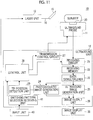
- the ultrasound unit 12 includes the receiving circuit 21, a receiving memory 22, a data demultiplexing unit 23, a photoacoustic image generation unit 24, an ultrasound image generation unit 25, an image output unit 26, a transmission control circuit 27, the control unit 28, and a tip position detection unit 29.
- the ultrasound unit 12 typically includes, for example, a processor, a memory, and a bus.
- a program related to, for example, a photoacoustic image generation process, an ultrasound image generation process, and a process of detecting the position of the tip of the puncture needle 15 in a photoacoustic image is incorporated into a memory in the ultrasound unit 12.
- the program is executed by the control unit 28 which is formed by a processor to implement the functions of the data demultiplexing unit 23, the photoacoustic image generation unit 24, the ultrasound image generation unit 25, the image output unit 26, and the tip position detection unit 29. That is, each of these units is formed by the processor and the memory into which the program has been incorporated.
- the hardware configuration of the ultrasound unit 12 is not particularly limited and can be implemented by an appropriate combination of, for example, a plurality of integrated circuits (ICs), a processor, an application specific integrated circuit (ASIC), a field-programmable gate array (FPGA), and a memory.
- ICs integrated circuits
- ASIC application specific integrated circuit
- FPGA field-programmable gate array
- the receiving circuit 21 receives a detection signal output from the ultrasound probe 11 and stores the received detection signal in the receiving memory 22.
- the receiving circuit 21 according to this embodiment has 64 channels.
- the receiving circuit 21 typically includes a low-noise amplifier, a variable-gain amplifier, a low-pass filter, and an analog-to-digital converter (AD converter).
- the detection signal of the ultrasound probe 11 is amplified by the low noise amplifier.
- gain adjustment corresponding to a depth is performed by the variable-gain amplifier and a high-frequency component of the detection signal is cut by the low-pass filter.
- the detection signal is converted into a digital signal by the AD converter and the digital signal is stored in the receiving memory 22.
- the receiving circuit 21 is formed by, for example, one integral circuit (IC).
- the ultrasound probe 11 outputs a detection signal of the photoacoustic waves and a detection signal of the reflected ultrasonic waves.
- the AD-converted detection signals (sampling data) of the photoacoustic waves and the reflected ultrasonic waves are stored in the receiving memory 22.
- the data demultiplexing unit 23 reads the detection signal of the photoacoustic waves from the receiving memory 22 and transmits the detection signal to the photoacoustic image generation unit 24.
- the data demultiplexing unit 23 reads the detection signal of the reflected ultrasonic waves from the receiving memory 22 and transmits the detection signal to the ultrasound image generation unit 25.
- the photoacoustic image generation unit 24 generates a photoacoustic image on the basis of the detection signal of the photoacoustic waves detected by the ultrasound probe 11.
- the photoacoustic image generation process includes, for example, image reconfiguration, such as phasing addition, detection, and logarithmic conversion.
- the ultrasound image generation unit 25 generates an ultrasound image (reflected acoustic image) on the basis of the detection signal of the reflected ultrasonic waves detected by the ultrasound probe 11.
- the ultrasound image generation process includes, for example, image reconfiguration, such as phasing addition, detection, and logarithmic conversion.
- the image output unit 26 outputs the photoacoustic image and the ultrasound image to an image display unit 30 such as a display device.
- the tip position detection unit 29 detects the position of a tip portion of the puncture needle 15 on the basis of the photoacoustic image generated by the photoacoustic image generation unit 24.
- any method may be used as long as it can detect the position of a maximum brightness point in the photoacoustic image as the position of the tip portion of the puncture needle 15.
- the photoacoustic image generated by the photoacoustic image generation unit 24 is not used as it is, but, for example, a smoothing process may be performed for the photoacoustic image to prevent erroneous detection caused by the artifact.
- the smoothing process is performed for the photoacoustic image subjected to detection and logarithmic conversion.
- a filtering process using a Gaussian filter can be used as the smoothing process. It is preferable that the size of the Gaussian filter is less than that of the tip portion of the puncture needle 15.
- a binarization process is performed for the photoacoustic image subjected to the smoothing process to generate a binary image. Then, a region in which white pixels are continuously distributed is detected from the binary image to detect the position of the tip portion of the puncture needle 15. In this way, it is possible to detect the position of the tip portion of the puncture needle 15 with higher accuracy.
- the control unit 28 controls each component in the ultrasound unit 12. For example, in a case in which a photoacoustic image is acquired, the control unit 28 transmits a trigger signal to the laser unit 13 such that the laser unit 13 emits laser light. In addition, the control unit 28 transmits a sampling trigger signal to the receiving circuit 21 to control, for example, the sampling start time of the photoacoustic waves with the emission of the laser light.
- the control unit 28 controls the multiplexer 20c of the acoustic wave detection unit 20 to specify 64 piezoelectric element groups connected to the receiving circuit 21 as described above.
- the control unit 28 specifies 64 piezoelectric element groups (hereinafter, simply referred to as piezoelectric element groups) on the basis of the position of the tip portion of the puncture needle 15 detected by the tip position detection unit 29.
- the control unit 28 according to this embodiment sequentially specifies the piezoelectric element groups in real time, following a change in the position of the tip portion of the puncture needle 15, such that the position of the tip portion of the puncture needle 15 is always located at the center of the receiving region of the piezoelectric element group.
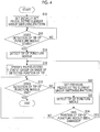
- a method for specifying the piezoelectric element group will be described with reference to a flowchart illustrated in Fig. 4 .
- the control unit 28 sets the initially set piezoelectric element group switching pattern that has been stored in advance (S10).
- a pattern of switching a piezoelectric element group in the left half of the piezoelectric element array 20b and a piezoelectric element group in the right half of the piezoelectric element array 20b is set as the initially set piezoelectric element group switching pattern.
- the arrangement direction of the piezoelectric elements 20a is a left-right direction.
- the initially set piezoelectric element group switching pattern is not limited thereto and may be other patterns.
- the control unit 28 checks whether the user has input a command to start the detection of the tip of the puncture needle 15. In a case in which the tip detection start command has been input (S12, YES), the control unit 28 starts a process of detecting the position of the tip portion of the puncture needle 15 (S14). In addition, the user inputs the tip detection start command and a tip detection end command with an input unit 40 (see Fig. 1 ).
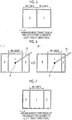
- the control unit 28 switches the piezoelectric element group in the left half and the piezoelectric element group in the right half to switch a receiving region I of the piezoelectric element group in the right half and a receiving region II of the piezoelectric element group in the left half illustrated in Fig. 5 , thereby acquiring the detection signals of the photoacoustic waves from all of the receiving regions. That is, first, the control unit 28 acquires a detection signal of the receiving region I of the piezoelectric element group in the right half and stores the detection signal in the receiving memory 22. Then, the control unit 28 acquires a detection signal of the receiving region II of the piezoelectric element group in the left half and stores the detection signal in the receiving memory 22.
- Each of 64 lines illustrated in Fig. 5 is a region of the subject from which a detection signal is acquired by phasing addition centering on each piezoelectric element.
- the data demultiplexing unit 23 transmits the detection signals of all of the receiving regions from the receiving memory 22 to the photoacoustic image generation unit 24 and the photoacoustic image generation unit 24 generates a photoacoustic image corresponding to one frame.
- a photoacoustic image of one frame generated by the photoacoustic image generation unit 24 is input to the tip position detection unit 29.
- the tip position detection unit 29 detects the position of the tip portion of the puncture needle 15.
- the positional information of the tip portion detected by the tip position detection unit 29 is input to the control unit 28 and the control unit 28 specifies the piezoelectric element group used in a case in which a photoacoustic image of the next frame is acquired, on the basis of the input positional information of the tip portion (S16).
- the control unit 28 specifies a receiving region I in which the tip portion P is located at the center and specifies a piezoelectric element group corresponding to the receiving region I.
- the control unit 28 acquires a detection signal of the receiving region I of the specified piezoelectric element group in the receiving memory 22.
- the control unit 28 acquires a detection signal of the other receiving region II and stores the detection signal in the receiving memory 22.
- the detection signals of all of the receiving regions are transmitted from the receiving memory 22 to the photoacoustic image generation unit 24.
- the photoacoustic image generation unit 24 generates a photoacoustic image of one frame.
- the image output unit 26 displays the photoacoustic image of one frame on the image display unit 30.
- the piezoelectric element group corresponding to the receiving region I in which the tip portion P of the puncture needle 15 is located at the center is specified. Therefore, it is possible to appropriately acquire the detection signal of the tip portion P of the puncture needle 15 and an image of the tip portion P of the puncture needle 15 is clearly displayed on a photoacoustic image.
- control unit 28 checks whether the user has input a command to end the detection of the tip of the puncture needle 15 (S18). In a case in which the tip detection end command has not been input, the control unit 28 sets the previously set piezoelectric element group switching pattern (S20).
- the receiving region I and the receiving region II illustrated in (I) of Fig. 6 are set again.
- the detection signal of the receiving region I is acquired and then the detection signal of the receiving region II are acquired.
- a photoacoustic image based on the detection signals is input to the tip position detection unit 29 and the position of the tip portion of the puncture needle 15 is detected (S22).
- the receiving region I and the receiving region II are set again (S20) and the position of the tip portion of the puncture needle 15 is detected again (S22).
- the process returns to S16.
- a receiving region I having the changed position of the tip portion P at the center is specified and a piezoelectric element group corresponding to the receiving region I is specified.
- the detection signal of the receiving region I of the specified piezoelectric element group is acquired and stored in the receiving memory 22.
- the detection signal of the other receiving region II is acquired and stored in the receiving memory 22.
- the detection signals of all of the receiving regions are transmitted from the receiving memory 22 to the photoacoustic image generation unit 24 and the photoacoustic image generation unit 24 generates a photoacoustic image corresponding to one frame.
- the image output unit 26 displays the photoacoustic image of one frame on the image display unit 30.
- the tip position detection unit 29 detects the position of the tip portion of the puncture needle 15 in time series on the basis of the photoacoustic image generated in time series and the control unit 28 sequentially specifies the piezoelectric element groups on the basis of the position of the tip portion of the puncture needle 15 detected in time series.
- the piezoelectric element groups are sequentially specified on the basis of the position of the tip portion of the puncture needle 15, it is possible to appropriately acquire the detection signal of the tip portion of the puncture needle 15 and to more clearly display the tip portion of the puncture needle 15 on a photoacoustic image.
- the control unit 28 transmits an ultrasonic wave transmission trigger signal for commanding the transmission of ultrasonic waves to the transmission control circuit 27.
- the transmission control circuit 27 directs the ultrasound probe 11 to transmit ultrasonic waves.
- the ultrasound probe 11 scans the receiving region of the piezoelectric element group line by line to detect the reflected ultrasonic waves under the control of the control unit 28.
- the control unit 28 transmits a sampling trigger signal to the receiving circuit 21 according to an ultrasonic wave transmission time to start the sampling of the reflected ultrasonic waves. Sampling data received by the receiving circuit 21 is stored in the receiving memory 22.
- the ultrasound image generation unit 25 receives the sampling data of the detection signal of the reflected ultrasonic waves through the data demultiplexing unit 23 and generates an ultrasound image.
- the ultrasound image generated by the ultrasound image generation unit 25 is input to the image output unit 26 and the image output unit 26 displays the ultrasound image on the image display unit 30.
- the photoacoustic image and the ultrasound image may be separately displayed or may be combined and displayed.
- the photoacoustic image and the ultrasound image are combined and displayed, it is possible to check the position of the tip of the puncture needle 15 in a living body and thus to perform accurate and safe needling.
- the piezoelectric element groups are sequentially specified in real time, following a change in the position of the tip portion of the puncture needle 15, such that the tip portion of the puncture needle 15 is always located at the center of the receiving region of the piezoelectric element group.
- a plurality of piezoelectric element group switching patterns are stored in advance and any one of the plurality of switching patterns is selected on the basis of the position of the tip portion of the puncture needle 15.
- the other configurations and operations are the same as those in the photoacoustic image generation apparatus 10 according to the first embodiment.
- a switching pattern illustrated in Fig. 7 is stored in advance in the control unit 28 of the photoacoustic image generation apparatus 10 according to the second embodiment.
- the switching pattern illustrated in Fig. 7 is a pattern of switching two piezoelectric element groups, that is, a piezoelectric element group in a central portion of the piezoelectric element array 20b and a piezoelectric element group on the left and right sides of the central portion.
- the boundary between the receiving region I of the piezoelectric element group in the right half and the receiving region II of the piezoelectric element group in the left half illustrated in Fig. 5 is set so as to be included in a receiving region I of the piezoelectric element group in the central portion illustrated in Fig. 7 .
- control unit 28 selects one of the switching pattern illustrated in Fig. 5 and the switching pattern illustrated in Fig. 7 on the basis of the position of the tip portion of the puncture needle 15 and sets the selected switching pattern.
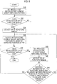
- a piezoelectric element group specification method according to the second embodiment will be described with reference to a flowchart illustrated in Fig. 8 .
- the control unit 28 sets the initially set piezoelectric element group switching pattern that has been stored in advance, as in the first embodiment (S30).
- the switching pattern illustrated in Fig. 5 is set as the initially set piezoelectric element group switching pattern.
- the initially set piezoelectric element group switching pattern is not limited thereto and may be other patterns.
- control unit 28 checks whether the user has input a command to start the detection of the tip of the puncture needle 15. In a case in which the tip detection start command has been input (S32, YES), the control unit 28 starts a process of detecting the position of the tip portion of the puncture needle 15 (S34).
- the control unit 28 switches the piezoelectric element group in the left half and the piezoelectric element group in the right half to switch the receiving region I of the piezoelectric element group in the right half and the receiving region II of the piezoelectric element group in the left half illustrated in Fig. 5 , thereby acquiring the detection signals of all of the receiving regions. That is, first, the control unit 28 acquires the detection signal of the receiving region I of the piezoelectric element group in the right half and stores the detection signal in the receiving memory 22. Then, the control unit 28 acquires the detection signal of the receiving region II of the piezoelectric element group in the left half and stores the detection signals in the receiving memory 22.
- the data demultiplexing unit 23 transmits the detection signals of all of the receiving regions from the receiving memory 22 to the photoacoustic image generation unit 24 and the photoacoustic image generation unit 24 generates a photoacoustic image corresponding to one frame.
- the photoacoustic image of one frame generated by the photoacoustic image generation unit 24 is input to the tip position detection unit 29.
- the tip position detection unit 29 detects the position of the tip portion of the puncture needle 15 (S34).
- the positional information of the tip portion detected by the tip position detection unit 29 is input to the control unit 28 and the control unit 28 selects a piezoelectric element group switching pattern used in a case in which a photoacoustic image of the next frame is acquired, on the basis of the input positional information of the tip portion (S36).
- the switching pattern illustrated in Fig. 7 is selected.
- the switching pattern illustrated in Fig. 5 is continuously selected and set.
- the hatched range illustrated in Fig. 9 includes a boundary C between the receiving region I of the piezoelectric element group in the right half and the receiving region II of the piezoelectric element group in the left half illustrated in Fig. 5 and has a width of W on the left and right sides of the boundary C as a center line.
- the width of W is preset by the user.
- the boundary between the receiving region I and the receiving region II in the switching pattern illustrated in Fig. 7 is represented by a dotted line.
- the width of W is set so as not to include the boundary between the receiving region I and the receiving region II in the switching pattern illustrated in Fig. 7 .
- the detection signal of the receiving region I of the selected switching pattern is acquired and stored in the receiving memory 22.
- the detection signal of the other receiving region II is acquired and stored in the receiving memory 22.
- the detection signals of all of the receiving regions are transmitted from the receiving memory 22 to the photoacoustic image generation unit 24.
- the photoacoustic image generation unit 24 generates a photoacoustic image of one frame and the image output unit 26 displays the photoacoustic image of one frame on the image display unit 30.
- the piezoelectric element group switching pattern is selected such that the tip portion P of the puncture needle 15 is not included in a boundary portion between the receiving regions. Therefore, it is possible to appropriately acquire the detection signal of the tip portion P of the puncture needle 15 and the image of the tip portion P of the puncture needle 15 is clearly displayed on a photoacoustic image.
- control unit 28 checks whether the user has input a command to end the detection of the tip of the puncture needle 15 (S38). In a case in which the tip detection end command has not been input, the control unit 28 sets the previously set piezoelectric element group switching pattern (S40).
- the detection signal of the receiving region I is acquired again, the detection signal of the receiving region II is acquired and a photoacoustic image based on the detection signals is input to the tip position detection unit 29. Then, the position of the tip portion of the puncture needle 15 is detected (S42).
- the process returns to S36 and the switching pattern is changed.
- the switching pattern is changed to the switching pattern illustrated in Fig. 7 .
- the switching pattern is changed to the switching pattern illustrated in Fig. 5 .
- the same receiving regions I and II are set again (S40) and the position of the tip portion of the puncture needle 15 is detected again (S42). Then, the detection signal of the set receiving region I is acquired and stored in the receiving memory 22. Then, the detection signal of the other receiving region II is acquired and stored in the receiving memory 22.
- the detection signals of all of the receiving regions are transmitted from the receiving memory 22 to the photoacoustic image generation unit 24 and the photoacoustic image generation unit 24 generates a photoacoustic image corresponding to one frame.
- the image output unit 26 displays the photoacoustic image corresponding to one frame on the image display unit 30.
- a plurality of preset switching patterns are selected on the basis of the position of the tip portion of the puncture needle 15 and are then used. Therefore, it is possible to simplify the process and thus to increase a processing speed, as compared to a case in which the piezoelectric element groups are sequentially specified according to the position of the tip portion of the puncture needle 15 as in the photoacoustic image generation apparatus 10 according to the first embodiment.
- Fig. 10 illustrates four switching patterns.
- (I) of Fig. 10 illustrates a pattern of switching a piezoelectric element group in the right half and a piezoelectric element group in the left half, similarly to the switching pattern illustrated in Fig. 5 .
- (III) of Fig. 10 illustrates a pattern of switching two piezoelectric element groups, that is, a piezoelectric element group in a central portion of the piezoelectric element array 20b and a piezoelectric element group on the left and right sides of the central portion, similarly to the switching pattern illustrated in Fig.
- FIG. 10 illustrates a switching pattern in which a receiving region I including both the boundary between the receiving regions in the switching pattern illustrated in (I) of Fig. 10 and the right boundary between the receiving regions in the switching pattern illustrated in (III) of Fig. 10 and a receiving region II on the left and right sides of the receiving region I are set.
- (IV) of Fig. 10 illustrates a switching pattern in which a receiving region I including both the boundary between the receiving regions in the switching pattern illustrated in (I) of Fig. 10 and the left boundary between the receiving regions in the switching pattern illustrated in (III) of Fig. 10 and a receiving region II on the left and right sides of the receiving region I are set.
- the receiving region I in the switching pattern illustrated in (II) of Fig. 10 is set such that the center thereof is located on the right side of the center of the piezoelectric element array 20b.
- the center of the receiving region I in the switching pattern illustrated in (IV) of Fig. 10 is set such that the center thereof is located on the left side of the center of the piezoelectric element array 20b.
- the switching pattern illustrated in Fig. 5 is set as the initially set switching pattern.
- one switching pattern is set as the initially set switching pattern, for example, in a case in which the puncture needle 15 is inserted into the vicinity of the boundary between the receiving region I and the receiving region II in the switching pattern illustrated in Fig. 5 , there is a possibility that the position of the tip portion of the puncture needle 15 will not be appropriately detected.
- a plurality of switching patterns may be alternately set as the initial setting and each photoacoustic image corresponding to each switching pattern may be alternately generated such that the tip position detection unit 29 can detect the position of the tip portion of the puncture needle 15 on the basis of any one of the photoacoustic images.
- the switching pattern illustrated in Fig. 5 and the switching pattern illustrated in Fig. 7 may be set as the initial settings and each photoacoustic image corresponding to each switching pattern may be alternately generated.
- the invention is not limited to the configuration in which the switching patterns are set before the position of the tip portion of the puncture needle 15 is detected.
- the control unit 28 may alternately set a plurality of switching patterns and alternately generate each photoacoustic image corresponding to each switching pattern such that the tip position detection unit 29 can detect the position of the tip portion of the puncture needle 15 on the basis of any one of the photoacoustic images.
- the user may select the initially set switching pattern before the position of the tip portion of the puncture needle 15 is detected.
- a switching pattern selection receiving unit 41 that receives the selection of the initially set switching pattern may be provided and the control unit 28 may set the switching pattern received by the switching pattern selection receiving unit 41 as the initial setting.
- an icon indicating the switching pattern illustrated in Fig. 5 and an icon indicating the switching pattern illustrated in Fig. 7 may be displayed on the image display unit 30 such that the user can select any one of the icons.
- the selection of the switching pattern may not be directly received unlike the above, but the selection of the switching pattern may be received by, for example, receiving information indicating whether the selection of a highlighting process for the puncture needle 15 is present or absent.
- the highlighting process for the puncture needle 15 is a process of highlighting the image of the puncture needle 15 in an ultrasound image without using a photoacoustic image and is, for example, a contrast enhancement process.
- a technique such as a so-called parallel method or a so-called crossing method, is used.
- the parallel method is a method which performs needling such that the piezoelectric element array 20b of the ultrasound probe 11 is disposed along the length direction of the puncture needle 15.
- the crossing method is a method which performs needling such that the piezoelectric element array 20b of the ultrasound probe 11 is disposed along a direction intersecting the length direction of the puncture needle 15.
- the image of the puncture needle 15 appears in a linear shape in a photoacoustic image acquired by the parallel method.
- the image of the puncture needle 15 appears in a dot shape in a photoacoustic image acquired by the crossing method.
- the highlighting process highlights a linear image acquired by the parallel method. Therefore, in a case in which the user selects the highlighting process for the puncture needle 15, it can be determined that a photoacoustic image has been acquired by the parallel method.
- the puncture needle 15 is inserted in one of the left and right directions with respect to the piezoelectric element array 20b of the ultrasound probe 11. Therefore, it is preferable that the initially set switching pattern is the switching pattern illustrated in Fig. 5 .
- the puncture needle 15 is inserted from the vicinity of the center of the piezoelectric element array 20b of the ultrasound probe 11. Therefore, it is preferable that the initially set switching pattern is the switching pattern illustrated in Fig. 7 .
- the control unit 28 checks whether the user has selected the highlighting process for the puncture needle 15. In a case in which the highlighting process has been selected (S50, YES), the control unit 28 determines that a photoacoustic image is acquired by the parallel method and sets the first switching pattern illustrated in Fig. 5 as the initial setting (S52). On the other hand, in a case in which the highlighting process has not been selected (S50, NO), the control unit 28 determines that a photoacoustic image is acquired by the crossing method and sets the second switching pattern illustrated in Fig. 7 as the initial setting (S54).
- the puncture needle 15 is used as an embodiment of the insert.
- the insert may be a radio-frequency ablation needle including an electrode that is used for radio-frequency ablation, a catheter that is inserted into a blood vessel, or a guide wire for a catheter that is inserted into a blood vessel.
- the insert may be an optical fiber for laser treatment.
- the needle according to the invention is not limited to a needle, such as an injection needle, and may be a biopsy needle used for biopsy. That is, the needle may be a biopsy needle that is inserted into an inspection target of the living body and extracts the tissues of a biopsy site of the inspection target. In this case, photoacoustic waves may be generated from an extraction portion (intake port) for sucking and extracting the tissues of the biopsy site.
- the needle may be used as a guiding needle that is used for insertion into a deep part, such as a part under the skin or an organ inside the abdomen.
Landscapes
- Engineering & Computer Science (AREA)
- Health & Medical Sciences (AREA)
- Life Sciences & Earth Sciences (AREA)
- Physics & Mathematics (AREA)
- Radar, Positioning & Navigation (AREA)
- Remote Sensing (AREA)
- General Health & Medical Sciences (AREA)
- Pathology (AREA)
- Medical Informatics (AREA)
- Acoustics & Sound (AREA)
- Molecular Biology (AREA)
- Animal Behavior & Ethology (AREA)
- Veterinary Medicine (AREA)
- Biomedical Technology (AREA)
- Heart & Thoracic Surgery (AREA)
- Biophysics (AREA)
- Public Health (AREA)
- Surgery (AREA)
- General Physics & Mathematics (AREA)
- Computer Networks & Wireless Communication (AREA)
- Nuclear Medicine, Radiotherapy & Molecular Imaging (AREA)
- Radiology & Medical Imaging (AREA)
- Human Computer Interaction (AREA)
- Analytical Chemistry (AREA)
- Chemical & Material Sciences (AREA)
- Optics & Photonics (AREA)
- Biochemistry (AREA)
- Immunology (AREA)
- Quality & Reliability (AREA)
- Computer Vision & Pattern Recognition (AREA)
- Theoretical Computer Science (AREA)
- Ultra Sonic Daignosis Equipment (AREA)
Abstract
Description
- The present invention relates to a photoacoustic image generation apparatus comprising an insert of which at least a portion is inserted into a subject and which includes a photoacoustic wave generation portion that absorbs light and generates photoacoustic waves.
- An ultrasonography method has been known as a kind of image inspection method that can non-invasively inspect the internal state of a living body. In ultrasonography, an ultrasound probe that can transmit and receive ultrasonic waves is used. In a case in which the ultrasound probe transmits ultrasonic waves to a subject (living body), the ultrasonic waves travel in the living body and are reflected from the interface between tissues. The ultrasound probe receives the reflected ultrasonic waves and a distance is calculated on the basis of the time until the reflected ultrasonic waves return to the ultrasound probe. In this way, it is possible to capture an image indicating the internal aspect of the living body.
- In addition, photoacoustic imaging has been known which captures the image of the inside of a living body using a photoacoustic effect. In general, in the photoacoustic imaging, the inside of the living body is irradiated with pulsed laser light. In the inside of the living body, a living body tissue absorbs the energy of the pulsed laser light and ultrasonic waves (photoacoustic waves) are generated by adiabatic expansion caused by the energy. For example, an ultrasound probe detects the photoacoustic waves and a photoacoustic image is formed on the basis of a detection signal. In this way, it is possible to visualize the inside of the living body on the basis of the photoacoustic waves.
- In addition, as a technique related to the photoacoustic imaging,
JP2015-231583A - Here, for example, in a case in which photoacoustic imaging is performed using the puncture needle disclosed in
JP2015-231583A - The piezoelectric element array of the ultrasound probe is formed by one-dimensionally arranging, for example, 128 piezoelectric elements and a receiving circuit receives a detection signal detected by the piezoelectric element through a multiplexer.
- In general, the number of channels that can be received by the receiving circuit at the same time is limited. For example, in a case in which a 64-channel receiving circuit is used and 128 piezoelectric elements are provided as described above, the number of channels in the receiving circuit is less than the number of piezoelectric elements in the piezoelectric element array. Therefore, 128 detection elements are divided into detection element groups each of which include 64 detection elements and each of the divided detection element groups is selectively connected to the receiving circuit by a multiplexer with a ratio of 1:2.
- However, for example, in a case in which a tip portion of the puncture needle is located at the boundary between the photoacoustic wave receiving regions of the detection element groups, it may be difficult to appropriately acquire a detection signal of the tip portion and to clearly display the tip portion of the puncture needle.
- In addition,
WO2012/008217A ,JP2003-61955A JP1994-205773A JP-H06-205773A - The invention has been made in view of the above-mentioned problems and an object of the invention is to provide a photoacoustic image generation apparatus that can appropriately acquire a detection signal of a tip portion of an insert, such as a puncture needle, and can more clearly display the tip portion of the insert.
- A photoacoustic image generation apparatus according to the invention comprises: an insert of which at least a tip portion is inserted into a subject and which includes a light guide member that guides light to the tip portion and a photoacoustic wave generation portion that absorbs the light guided by the light guide member and generates photoacoustic waves; an acoustic wave detection unit having a detection element array in which a plurality of detection elements that detect the photoacoustic waves are arranged; a control unit that controls the acoustic wave detection unit to specify some detection element groups in the detection element array and switches the detection element groups to switch receiving regions of the photoacoustic waves, thereby acquiring detection signals of all of the receiving regions in the detection element array; a photoacoustic image generation unit that generates a photoacoustic image on the basis of the detection signals of the photoacoustic waves; and a tip position detection unit that detects a position of the tip portion of the insert on the basis of the photoacoustic image. The control unit specifies the detection element groups on the basis of the position of the tip portion of the insert detected by the tip position detection unit.
- In the photoacoustic image generation apparatus according to the invention, the tip position detection unit may detect the position of the tip portion of the insert in time series on the basis of the photoacoustic image generated in time series and the control unit may sequentially specify the detection element groups on the basis of the position of the tip portion of the insert detected in time series.
- In the photoacoustic image generation apparatus according to the invention, the control unit may store a plurality of switching patterns for the detection element groups in advance and the control unit may select any one of the plurality of switching patterns on the basis of the position of the tip portion of the insert and switch the detection element groups using the selected switching pattern.
- In the photoacoustic image generation apparatus according to the invention, preferably, in a case in which the detection element array is formed by arranging the plurality of detection elements in at least one row and the arrangement direction is a left-right direction, one of the switching patterns for the detection element groups may be a pattern of switching two detection element groups, that is, a detection element group in a left half of the detection element array and a detection element group in a right half of the detection element array.
- In the photoacoustic image generation apparatus according to the invention, one of the switching patterns for the detection element groups may be a pattern of switching two detection element groups, that is, a detection element group in a central portion of the detection element array and a detection element group on the left and right sides of the central portion of the detection element array and the control unit may select one of the pattern of switching the two detection element groups, that is, the detection element group in the left half of the detection element array and the detection element group in the right half of the detection element array and the pattern of switching the two detection element groups, that is, the detection element group in the central portion of the detection element array and the detection element group on the left and right sides of the central portion of the detection element array, on the basis of the position of the tip portion of the insert.
- In the photoacoustic image generation apparatus according to the invention, preferably, a boundary between a receiving region of the detection element group in the left half of the detection element array and a receiving region the detection element group in the right half of the detection element array is included in a receiving region of the detection element group in the central portion of the detection element array.
- In the photoacoustic image generation apparatus according to the invention, in a case in which a distance between the position of the tip portion of the insert and the boundary between the receiving regions of the detection element groups is equal to or less than a predetermined threshold value, the control unit may change the switching pattern.
- In the photoacoustic image generation apparatus according to the invention, the control unit may alternately set the plurality of switching patterns before the position of the tip portion of the insert is detected and the tip position detection unit may detect the position of the tip portion of the insert on the basis of each photoacoustic image corresponding to each of the switching patterns.
- In the photoacoustic image generation apparatus according to the invention, in a case in which the tip position detection unit is not capable of detecting the position of the tip portion of the insert, the control unit may alternately set the plurality of switching patterns and the tip position detection unit may detect the position of the tip portion of the insert on the basis of each photoacoustic image corresponding to each of the switching patterns.
- The photoacoustic image generation apparatus according to the invention may further comprise a switching pattern selection receiving unit that receives a selection of the switching pattern initially set before the position of the tip portion of the insert is detected.
- In the photoacoustic image generation apparatus according to the invention, the switching pattern selection receiving unit may receive a selection of a highlighting process for the insert as the selection of the initially set switching pattern.
- In the photoacoustic image generation apparatus according to the invention, preferably, the insert is a needle that is inserted into the subject.
- The photoacoustic image generation apparatus according to the invention controls the acoustic wave detection unit having the detection element array to specify some detection element groups in the detection element array, switches some detection element groups to switch photoacoustic wave receiving regions, thereby acquiring the detection signals of all of the receiving regions in the detection element array, and generates a photoacoustic image on the basis of the detection signals.
- Then, the photoacoustic image generation apparatus detects the position of the tip portion of the insert having the photoacoustic wave generation portion on the basis of the photoacoustic image and specifies some detection element groups on the basis of the detected position of the tip portion of the insert. Therefore, it is possible to appropriately acquire the detection signal of the tip portion of the insert and to clearly display the tip portion of the insert.
-
-
Fig. 1 is a block diagram schematically illustrating the configuration of a first embodiment of a photoacoustic image generation apparatus according to the invention. -
Fig. 2 is a cross-sectional view illustrating the configuration of a tip portion of a puncture needle. -
Fig. 3 is a block diagram schematically illustrating the configuration of an acoustic wave detection unit. -
Fig. 4 is a flowchart illustrating a method for specifying a piezoelectric element group in the photoacoustic image generation apparatus according to the first embodiment. -
Fig. 5 is a diagram illustrating an example of a piezoelectric element group switching pattern. -
Fig. 6 is a diagram illustrating the method for specifying the piezoelectric element group in the photoacoustic image generation apparatus according to the first embodiment. -
Fig. 7 is a diagram illustrating another example of the piezoelectric element group switching pattern. -
Fig. 8 is a flowchart illustrating a method for specifying a piezoelectric element group in a photoacoustic image generation apparatus according to a second embodiment. -
Fig. 9 is a diagram illustrating the method for specifying the piezoelectric element group in the photoacoustic image generation apparatus according to the second embodiment. -
Fig. 10 is a diagram illustrating an example of four switching patterns used in the photoacoustic image generation apparatus according to the second embodiment. -
Fig. 11 is a block diagram schematically illustrating another embodiment of the photoacoustic image generation apparatus according to the invention. -
Fig. 12 is a flowchart illustrating a method for specifying an initially set switching pattern on the basis of the selection of a needle highlighting process. - Hereinafter, a first embodiment of a photoacoustic image generation apparatus according to the invention will be described in detail with reference to the drawings.
Fig. 1 is a diagram schematically illustrating the configuration of a photoacousticimage generation apparatus 10 according to this embodiment. - As illustrated in
Fig. 1 , the photoacousticimage generation apparatus 10 according to this embodiment comprises anultrasound probe 11, anultrasound unit 12, alaser unit 13, and apuncture needle 15. Thepuncture needle 15 and thelaser unit 13 are connected by anoptical cable 16 having an optical fiber. Thepuncture needle 15 can be attached to and detached from theoptical cable 16 and is disposable. In addition, in this embodiment, ultrasonic waves are used as acoustic waves. However, the invention is not limited to the ultrasonic waves. Acoustic waves with an audible frequency may be used as long as an appropriate frequency can be selected according to, for example, an inspection target or measurement conditions. - The
laser unit 13 comprises a solid-state laser light source using, for example, yttrium aluminum garnet (YAG) and alexandrite. Laser light emitted from the solid-state laser light source of thelaser unit 13 is guided by theoptical cable 16 and is incident on thepuncture needle 15. Thelaser unit 13 according to this embodiment emits pulsed laser light in a near-infrared wavelength range. The near-infrared wavelength range means a wavelength range from 700 nm to 850 nm. In this embodiment, the solid-state laser light source is used. However, other laser light sources, such as a gas laser light source, may be used or light sources other than the laser light source may be used. - The
puncture needle 15 is an embodiment of an insert according to the invention and is a needle that is inserted into a subject.Fig. 2 is a cross-sectional view including a center axis that extends in a length direction of thepuncture needle 15. Thepuncture needle 15 includes a puncture needlemain body 15a that has an opening at an acute tip and is formed in a hollow shape, anoptical fiber 15b (corresponding to a light guide member according to the invention) that guides laser light emitted from thelaser unit 13 to the vicinity of the opening of thepuncture needle 15, and a photoacousticwave generation portion 15c that absorbs laser light emitted from theoptical fiber 15b and generates photoacoustic waves. - The
optical fiber 15b and the photoacousticwave generation portion 15c are provided in ahollow portion 15d of the puncture needlemain body 15a. For example, theoptical fiber 15b is connected to the optical fiber in the optical cable 16 (seeFig. 1 ) through an optical connector that is provided at the base end of thepuncture needle 15. For example, a laser light of 0.2 mJ is emitted from a light emission end of theoptical fiber 15b. - The photoacoustic
wave generation portion 15c is provided at the light emission end of theoptical fiber 15b and is provided in the vicinity of the tip of thepuncture needle 15 and in the inner wall of the puncture needlemain body 15a. The photoacousticwave generation portion 15c absorbs the laser light emitted from theoptical fiber 15b and generates photoacoustic waves. The photoacousticwave generation portion 15c is made of, for example, an epoxy resin, a polyurethane resin, a fluorine resin, and silicone rubber with which a black pigment is mixed. InFig. 2 , the photoacousticwave generation portion 15c is illustrated to be larger than theoptical fiber 15b. However, the invention is not limited thereto. The photoacousticwave generation portion 15c may have a size that is equal to the diameter of theoptical fiber 15b. - The photoacoustic
wave generation portion 15c is not limited to the above and a metal film or an oxide film having light absorptivity with respect to the wavelength of laser light may be used as the photoacoustic wave generation portion. An oxide film made of, for example, iron oxide, chromium oxide, or manganese oxide having high light absorptivity with respect to the wavelength of laser light can be used as the photoacousticwave generation portion 15c. Alternatively, a metal film made of, for example, titanium (Ti) or platinum (Pt) that has a lower light absorptivity than an oxide and has a higher biocompatibility than an oxide may be used as the photoacousticwave generation portion 15c. In addition, the position where the photoacousticwave generation portion 15c is provided is not limited to the inner wall of the puncture needlemain body 15a. For example, a metal film or an oxide film which is the photoacousticwave generation portion 15c may be formed on the light emission end of theoptical fiber 15b with a thickness of about 100 nm by vapor deposition such that the oxide film covers the light emission end. In this case, at least a portion of the laser light emitted from the light emission end of theoptical fiber 15b is absorbed by the metal film or the oxide film covering the light emission end and photoacoustic waves are generated from the metal film or the oxide film. - The vicinity of the tip of the
puncture needle 15 means a position where the photoacousticwave generation portion 15c can generate photoacoustic waves capable of imaging the position of the tip of thepuncture needle 15 with accuracy required for a needling operation in a case in which the tip of theoptical fiber 15b and the photoacousticwave generation portion 15c are disposed at the position. For example, the vicinity of the tip of thepuncture needle 15 is the range of 0 mm to 3 mm from the tip to the base end of thepuncture needle 15. In the subsequent embodiments, the meaning of the vicinity of the tip is the same as described above. - Returning to
Fig. 1 , theultrasound probe 11 detects the photoacoustic waves emitted from the photoacousticwave generation portion 15c after thepuncture needle 15 is inserted into the subject. Theultrasound probe 11 includes an acousticwave detection unit 20 that detects photoacoustic waves. - As illustrated in
Fig. 3 , the acousticwave detection unit 20 comprises apiezoelectric element array 20b (corresponding to a detection element array according to the invention) in which a plurality ofpiezoelectric elements 20a (corresponding to detection elements according to the invention) that detect photoacoustic waves are one-dimensionally arranged and amultiplexer 20c. Thepiezoelectric element 20a is an ultrasound transducer and is, for example, a piezoelectric element made of a polymer film, such as piezoelectric ceramics or polyvinylidene fluoride (PVDF). In addition, the acousticwave detection unit 20 comprises, for example, an acoustic lens, an acoustic matching layer, a backing material, and a control circuit for thepiezoelectric element array 20b which are not illustrated in the drawings. - The
piezoelectric element array 20b according to this embodiment comprises 128piezoelectric elements 20a. The arrangement and number ofpiezoelectric elements 20a are not limited thereto. For example, the number ofpiezoelectric elements 20a may be 256 or thepiezoelectric elements 20a may be two-dimensionally arranged. In the specification, the arrangement direction of the piezoelectric elements may be a one-dimensional direction in a case in which the piezoelectric elements are one-dimensionally arranged and may be one of two directions perpendicular to each other in a two-dimensional space in a case in which the piezoelectric elements are two-dimensionally arranged. It is preferable that the arrangement direction is a direction in which a large number of piezoelectric elements are arranged. - The
multiplexer 20c selectively connects some piezoelectric element groups that detect photoacoustic waves in parallel among thepiezoelectric elements 20a forming thepiezoelectric element array 20b to a receivingcircuit 21 of theultrasound unit 12. The piezoelectric element group is a set of thepiezoelectric elements 20a that detect photoacoustic waves in parallel. - A photoacoustic wave receiving region of the
piezoelectric element array 20b is divided into a plurality of receiving regions by the selective connection by themultiplexer 20c and a photoacoustic wave detection signal is acquired from each receiving region. In addition, the photoacoustic wave receiving region is a region of the subject from which photoacoustic waves can be received by the piezoelectric element groups. - Specifically, the
multiplexer 20c according to this embodiment has 64 channels and can acquire the detection signals of 64 piezoelectric element groups in parallel. 64 piezoelectric element groups connected to the receivingcircuit 21 by themultiplexer 20c are specified by acontrol unit 28 of theultrasound unit 12. Thecontrol unit 28 switches 64 piezoelectric element groups to switch the photoacoustic wave receiving regions, thereby acquiring the detection signals of all of the receiving regions of thepiezoelectric element array 20b. - The
ultrasound probe 11 performs the transmission of acoustic waves (ultrasonic waves) to the subject and the reception of reflected acoustic waves (reflected ultrasonic waves) with respect to the transmitted ultrasonic waves, in addition to the detection of the photoacoustic waves, using thepiezoelectric element array 20b of the acousticwave detection unit 20. The transmission and reception of the ultrasonic waves may be performed at different positions. For example, ultrasonic waves may be transmitted from a position different from the position of theultrasound probe 11 and thepiezoelectric element array 20b of theultrasound probe 11 may receive the reflected ultrasonic waves with respect to the transmitted ultrasonic waves. For example, a linear ultrasound probe, a convex ultrasound probe, or a sector ultrasound probe may be used as theultrasound probe 11. - The
ultrasound unit 12 includes the receivingcircuit 21, a receivingmemory 22, adata demultiplexing unit 23, a photoacousticimage generation unit 24, an ultrasoundimage generation unit 25, animage output unit 26, atransmission control circuit 27, thecontrol unit 28, and a tipposition detection unit 29. Theultrasound unit 12 typically includes, for example, a processor, a memory, and a bus. A program related to, for example, a photoacoustic image generation process, an ultrasound image generation process, and a process of detecting the position of the tip of thepuncture needle 15 in a photoacoustic image is incorporated into a memory in theultrasound unit 12. The program is executed by thecontrol unit 28 which is formed by a processor to implement the functions of thedata demultiplexing unit 23, the photoacousticimage generation unit 24, the ultrasoundimage generation unit 25, theimage output unit 26, and the tipposition detection unit 29. That is, each of these units is formed by the processor and the memory into which the program has been incorporated. - The hardware configuration of the
ultrasound unit 12 is not particularly limited and can be implemented by an appropriate combination of, for example, a plurality of integrated circuits (ICs), a processor, an application specific integrated circuit (ASIC), a field-programmable gate array (FPGA), and a memory. - The receiving
circuit 21 receives a detection signal output from theultrasound probe 11 and stores the received detection signal in the receivingmemory 22. The receivingcircuit 21 according to this embodiment has 64 channels. The receivingcircuit 21 typically includes a low-noise amplifier, a variable-gain amplifier, a low-pass filter, and an analog-to-digital converter (AD converter). The detection signal of theultrasound probe 11 is amplified by the low noise amplifier. Then, gain adjustment corresponding to a depth is performed by the variable-gain amplifier and a high-frequency component of the detection signal is cut by the low-pass filter. Then, the detection signal is converted into a digital signal by the AD converter and the digital signal is stored in the receivingmemory 22. The receivingcircuit 21 is formed by, for example, one integral circuit (IC). - The
ultrasound probe 11 outputs a detection signal of the photoacoustic waves and a detection signal of the reflected ultrasonic waves. The AD-converted detection signals (sampling data) of the photoacoustic waves and the reflected ultrasonic waves are stored in the receivingmemory 22. Thedata demultiplexing unit 23 reads the detection signal of the photoacoustic waves from the receivingmemory 22 and transmits the detection signal to the photoacousticimage generation unit 24. In addition, thedata demultiplexing unit 23 reads the detection signal of the reflected ultrasonic waves from the receivingmemory 22 and transmits the detection signal to the ultrasoundimage generation unit 25. - The photoacoustic
image generation unit 24 generates a photoacoustic image on the basis of the detection signal of the photoacoustic waves detected by theultrasound probe 11. The photoacoustic image generation process includes, for example, image reconfiguration, such as phasing addition, detection, and logarithmic conversion. The ultrasoundimage generation unit 25 generates an ultrasound image (reflected acoustic image) on the basis of the detection signal of the reflected ultrasonic waves detected by theultrasound probe 11. The ultrasound image generation process includes, for example, image reconfiguration, such as phasing addition, detection, and logarithmic conversion. Theimage output unit 26 outputs the photoacoustic image and the ultrasound image to animage display unit 30 such as a display device. - The tip
position detection unit 29 detects the position of a tip portion of thepuncture needle 15 on the basis of the photoacoustic image generated by the photoacousticimage generation unit 24. As a method for detecting the position of the tip portion of thepuncture needle 15, any method may be used as long as it can detect the position of a maximum brightness point in the photoacoustic image as the position of the tip portion of thepuncture needle 15. - In a case in which the position of the tip of the
puncture needle 15 is detected on the basis of the photoacoustic image as described above, in practice, an artifact of light or an artifact of sound is generated and a photoacoustic image in which photoacoustic waves are detected from a plurality of positions is likely to be generated and the original position of the tip portion of thepuncture needle 15 is unlikely to be specified. - For this reason, the photoacoustic image generated by the photoacoustic
image generation unit 24 is not used as it is, but, for example, a smoothing process may be performed for the photoacoustic image to prevent erroneous detection caused by the artifact. Specifically, the smoothing process is performed for the photoacoustic image subjected to detection and logarithmic conversion. For example, a filtering process using a Gaussian filter can be used as the smoothing process. It is preferable that the size of the Gaussian filter is less than that of the tip portion of thepuncture needle 15. - Then, a binarization process is performed for the photoacoustic image subjected to the smoothing process to generate a binary image. Then, a region in which white pixels are continuously distributed is detected from the binary image to detect the position of the tip portion of the
puncture needle 15. In this way, it is possible to detect the position of the tip portion of thepuncture needle 15 with higher accuracy. - The
control unit 28 controls each component in theultrasound unit 12. For example, in a case in which a photoacoustic image is acquired, thecontrol unit 28 transmits a trigger signal to thelaser unit 13 such that thelaser unit 13 emits laser light. In addition, thecontrol unit 28 transmits a sampling trigger signal to the receivingcircuit 21 to control, for example, the sampling start time of the photoacoustic waves with the emission of the laser light. - Here, the
control unit 28 according to this embodiment controls themultiplexer 20c of the acousticwave detection unit 20 to specify 64 piezoelectric element groups connected to the receivingcircuit 21 as described above. At that time, thecontrol unit 28 specifies 64 piezoelectric element groups (hereinafter, simply referred to as piezoelectric element groups) on the basis of the position of the tip portion of thepuncture needle 15 detected by the tipposition detection unit 29. Specifically, thecontrol unit 28 according to this embodiment sequentially specifies the piezoelectric element groups in real time, following a change in the position of the tip portion of thepuncture needle 15, such that the position of the tip portion of thepuncture needle 15 is always located at the center of the receiving region of the piezoelectric element group. Next, a method for specifying the piezoelectric element group will be described with reference to a flowchart illustrated inFig. 4 . - First, the
control unit 28 sets the initially set piezoelectric element group switching pattern that has been stored in advance (S10). In this embodiment, a pattern of switching a piezoelectric element group in the left half of thepiezoelectric element array 20b and a piezoelectric element group in the right half of thepiezoelectric element array 20b is set as the initially set piezoelectric element group switching pattern. Here, it is assumed that the arrangement direction of thepiezoelectric elements 20a is a left-right direction. In addition, the initially set piezoelectric element group switching pattern is not limited thereto and may be other patterns. - Then, the
control unit 28 checks whether the user has input a command to start the detection of the tip of thepuncture needle 15. In a case in which the tip detection start command has been input (S12, YES), thecontrol unit 28 starts a process of detecting the position of the tip portion of the puncture needle 15 (S14). In addition, the user inputs the tip detection start command and a tip detection end command with an input unit 40 (seeFig. 1 ). - Specifically, the
control unit 28 switches the piezoelectric element group in the left half and the piezoelectric element group in the right half to switch a receiving region I of the piezoelectric element group in the right half and a receiving region II of the piezoelectric element group in the left half illustrated inFig. 5 , thereby acquiring the detection signals of the photoacoustic waves from all of the receiving regions. That is, first, thecontrol unit 28 acquires a detection signal of the receiving region I of the piezoelectric element group in the right half and stores the detection signal in the receivingmemory 22. Then, thecontrol unit 28 acquires a detection signal of the receiving region II of the piezoelectric element group in the left half and stores the detection signal in the receivingmemory 22. Each of 64 lines illustrated inFig. 5 is a region of the subject from which a detection signal is acquired by phasing addition centering on each piezoelectric element. - Then, the
data demultiplexing unit 23 transmits the detection signals of all of the receiving regions from the receivingmemory 22 to the photoacousticimage generation unit 24 and the photoacousticimage generation unit 24 generates a photoacoustic image corresponding to one frame. - A photoacoustic image of one frame generated by the photoacoustic
image generation unit 24 is input to the tipposition detection unit 29. The tipposition detection unit 29 detects the position of the tip portion of thepuncture needle 15. - The positional information of the tip portion detected by the tip
position detection unit 29 is input to thecontrol unit 28 and thecontrol unit 28 specifies the piezoelectric element group used in a case in which a photoacoustic image of the next frame is acquired, on the basis of the input positional information of the tip portion (S16). Specifically, for example, in a case in which a tip portion P of thepuncture needle 15 is located at a position illustrated in (I) ofFig. 6 , thecontrol unit 28 specifies a receiving region I in which the tip portion P is located at the center and specifies a piezoelectric element group corresponding to the receiving region I. Then, thecontrol unit 28 acquires a detection signal of the receiving region I of the specified piezoelectric element group in the receivingmemory 22. Then, thecontrol unit 28 acquires a detection signal of the other receiving region II and stores the detection signal in the receivingmemory 22. - Then, the detection signals of all of the receiving regions are transmitted from the receiving
memory 22 to the photoacousticimage generation unit 24. The photoacousticimage generation unit 24 generates a photoacoustic image of one frame. Theimage output unit 26 displays the photoacoustic image of one frame on theimage display unit 30. In this embodiment, as described above, the piezoelectric element group corresponding to the receiving region I in which the tip portion P of thepuncture needle 15 is located at the center is specified. Therefore, it is possible to appropriately acquire the detection signal of the tip portion P of thepuncture needle 15 and an image of the tip portion P of thepuncture needle 15 is clearly displayed on a photoacoustic image. - Then, the
control unit 28 checks whether the user has input a command to end the detection of the tip of the puncture needle 15 (S18). In a case in which the tip detection end command has not been input, thecontrol unit 28 sets the previously set piezoelectric element group switching pattern (S20). - That is, the receiving region I and the receiving region II illustrated in (I) of
Fig. 6 are set again. The detection signal of the receiving region I is acquired and then the detection signal of the receiving region II are acquired. Then, a photoacoustic image based on the detection signals is input to the tipposition detection unit 29 and the position of the tip portion of thepuncture needle 15 is detected (S22). - Then, in a case in which the position of the tip portion of the
puncture needle 15 has not been changed and the tip detection end command has not been input (S24, NO and S18, NO), the receiving region I and the receiving region II are set again (S20) and the position of the tip portion of thepuncture needle 15 is detected again (S22). In contrast, in a case in which the position of the tip portion of thepuncture needle 15 has been changed as illustrated in (II) ofFig. 6 (S24, YES), the process returns to S16. A receiving region I having the changed position of the tip portion P at the center is specified and a piezoelectric element group corresponding to the receiving region I is specified. - Then, the detection signal of the receiving region I of the specified piezoelectric element group is acquired and stored in the receiving
memory 22. Then, the detection signal of the other receiving region II is acquired and stored in the receivingmemory 22. - Then, the detection signals of all of the receiving regions are transmitted from the receiving
memory 22 to the photoacousticimage generation unit 24 and the photoacousticimage generation unit 24 generates a photoacoustic image corresponding to one frame. Theimage output unit 26 displays the photoacoustic image of one frame on theimage display unit 30. - Then, the process from S16 to S24 is repeatedly performed. In a case in which the tip detection end command is input in S18, the process ends.
- As described above, in this embodiment, the tip
position detection unit 29 detects the position of the tip portion of thepuncture needle 15 in time series on the basis of the photoacoustic image generated in time series and thecontrol unit 28 sequentially specifies the piezoelectric element groups on the basis of the position of the tip portion of thepuncture needle 15 detected in time series. - As such, since the piezoelectric element groups are sequentially specified on the basis of the position of the tip portion of the
puncture needle 15, it is possible to appropriately acquire the detection signal of the tip portion of thepuncture needle 15 and to more clearly display the tip portion of thepuncture needle 15 on a photoacoustic image. - Then, in a case in which an ultrasound image is acquired, the
control unit 28 transmits an ultrasonic wave transmission trigger signal for commanding the transmission of ultrasonic waves to thetransmission control circuit 27. In a case in which the ultrasonic wave transmission trigger signal is received, thetransmission control circuit 27 directs theultrasound probe 11 to transmit ultrasonic waves. In a case in which an ultrasound image is acquired, for example, theultrasound probe 11 scans the receiving region of the piezoelectric element group line by line to detect the reflected ultrasonic waves under the control of thecontrol unit 28. Thecontrol unit 28 transmits a sampling trigger signal to the receivingcircuit 21 according to an ultrasonic wave transmission time to start the sampling of the reflected ultrasonic waves. Sampling data received by the receivingcircuit 21 is stored in the receivingmemory 22. - The ultrasound
image generation unit 25 receives the sampling data of the detection signal of the reflected ultrasonic waves through thedata demultiplexing unit 23 and generates an ultrasound image. The ultrasound image generated by the ultrasoundimage generation unit 25 is input to theimage output unit 26 and theimage output unit 26 displays the ultrasound image on theimage display unit 30. - In the
image display unit 30, the photoacoustic image and the ultrasound image may be separately displayed or may be combined and displayed. In a case in which the photoacoustic image and the ultrasound image are combined and displayed, it is possible to check the position of the tip of thepuncture needle 15 in a living body and thus to perform accurate and safe needling. - Next, a second embodiment of the photoacoustic image generation apparatus according to the invention will be described. In the photoacoustic
image generation apparatus 10 according to the first embodiment, the piezoelectric element groups are sequentially specified in real time, following a change in the position of the tip portion of thepuncture needle 15, such that the tip portion of thepuncture needle 15 is always located at the center of the receiving region of the piezoelectric element group. However, in a photoacousticimage generation apparatus 10 according to the second embodiment, a plurality of piezoelectric element group switching patterns are stored in advance and any one of the plurality of switching patterns is selected on the basis of the position of the tip portion of thepuncture needle 15. The other configurations and operations are the same as those in the photoacousticimage generation apparatus 10 according to the first embodiment. - In addition to the switching pattern illustrated in
Fig. 5 , a switching pattern illustrated inFig. 7 is stored in advance in thecontrol unit 28 of the photoacousticimage generation apparatus 10 according to the second embodiment. The switching pattern illustrated inFig. 7 is a pattern of switching two piezoelectric element groups, that is, a piezoelectric element group in a central portion of thepiezoelectric element array 20b and a piezoelectric element group on the left and right sides of the central portion. In addition, the boundary between the receiving region I of the piezoelectric element group in the right half and the receiving region II of the piezoelectric element group in the left half illustrated inFig. 5 is set so as to be included in a receiving region I of the piezoelectric element group in the central portion illustrated inFig. 7 . - Then, the
control unit 28 selects one of the switching pattern illustrated inFig. 5 and the switching pattern illustrated inFig. 7 on the basis of the position of the tip portion of thepuncture needle 15 and sets the selected switching pattern. Next, a piezoelectric element group specification method according to the second embodiment will be described with reference to a flowchart illustrated inFig. 8 . - First, the
control unit 28 sets the initially set piezoelectric element group switching pattern that has been stored in advance, as in the first embodiment (S30). In this embodiment, the switching pattern illustrated inFig. 5 is set as the initially set piezoelectric element group switching pattern. In the second embodiment, the initially set piezoelectric element group switching pattern is not limited thereto and may be other patterns. - Then, the
control unit 28 checks whether the user has input a command to start the detection of the tip of thepuncture needle 15. In a case in which the tip detection start command has been input (S32, YES), thecontrol unit 28 starts a process of detecting the position of the tip portion of the puncture needle 15 (S34). - Specifically, the
control unit 28 switches the piezoelectric element group in the left half and the piezoelectric element group in the right half to switch the receiving region I of the piezoelectric element group in the right half and the receiving region II of the piezoelectric element group in the left half illustrated inFig. 5 , thereby acquiring the detection signals of all of the receiving regions. That is, first, thecontrol unit 28 acquires the detection signal of the receiving region I of the piezoelectric element group in the right half and stores the detection signal in the receivingmemory 22. Then, thecontrol unit 28 acquires the detection signal of the receiving region II of the piezoelectric element group in the left half and stores the detection signals in the receivingmemory 22. - Then, the
data demultiplexing unit 23 transmits the detection signals of all of the receiving regions from the receivingmemory 22 to the photoacousticimage generation unit 24 and the photoacousticimage generation unit 24 generates a photoacoustic image corresponding to one frame. - The photoacoustic image of one frame generated by the photoacoustic
image generation unit 24 is input to the tipposition detection unit 29. The tipposition detection unit 29 detects the position of the tip portion of the puncture needle 15 (S34). - The positional information of the tip portion detected by the tip
position detection unit 29 is input to thecontrol unit 28 and thecontrol unit 28 selects a piezoelectric element group switching pattern used in a case in which a photoacoustic image of the next frame is acquired, on the basis of the input positional information of the tip portion (S36). - Specifically, for example, in a case in which the position of the tip portion P of the
puncture needle 15 is in a hatched range illustrated inFig. 9 , the switching pattern illustrated inFig. 7 is selected. In a case in which the position is out of the hatched range illustrated inFig. 9 , the switching pattern illustrated inFig. 5 is continuously selected and set. The hatched range illustrated inFig. 9 includes a boundary C between the receiving region I of the piezoelectric element group in the right half and the receiving region II of the piezoelectric element group in the left half illustrated inFig. 5 and has a width of W on the left and right sides of the boundary C as a center line. - The width of W is preset by the user. In
Fig. 9 , the boundary between the receiving region I and the receiving region II in the switching pattern illustrated inFig. 7 is represented by a dotted line. The width of W is set so as not to include the boundary between the receiving region I and the receiving region II in the switching pattern illustrated inFig. 7 . - Then, the detection signal of the receiving region I of the selected switching pattern is acquired and stored in the receiving
memory 22. Then, the detection signal of the other receiving region II is acquired and stored in the receivingmemory 22. - The detection signals of all of the receiving regions are transmitted from the receiving
memory 22 to the photoacousticimage generation unit 24. The photoacousticimage generation unit 24 generates a photoacoustic image of one frame and theimage output unit 26 displays the photoacoustic image of one frame on theimage display unit 30. In this embodiment, the piezoelectric element group switching pattern is selected such that the tip portion P of thepuncture needle 15 is not included in a boundary portion between the receiving regions. Therefore, it is possible to appropriately acquire the detection signal of the tip portion P of thepuncture needle 15 and the image of the tip portion P of thepuncture needle 15 is clearly displayed on a photoacoustic image. - Then, the
control unit 28 checks whether the user has input a command to end the detection of the tip of the puncture needle 15 (S38). In a case in which the tip detection end command has not been input, thecontrol unit 28 sets the previously set piezoelectric element group switching pattern (S40). - That is, after the detection signal of the receiving region I is acquired again, the detection signal of the receiving region II is acquired and a photoacoustic image based on the detection signals is input to the tip
position detection unit 29. Then, the position of the tip portion of thepuncture needle 15 is detected (S42). - Then, in a case in which a distance between the position of the tip portion of the
puncture needle 15 and the boundary between the receiving region I and the receiving region II in the currently set switching pattern is equal to or less than a threshold value (S44, YES), the process returns to S36 and the switching pattern is changed. Specifically, in this embodiment, in a case in which the currently set switching pattern is the switching pattern illustrated inFig. 5 and the position of the tip portion P of thepuncture needle 15 is within the hatched range illustrated inFig. 9 , the switching pattern is changed to the switching pattern illustrated inFig. 7 . On the other hand, in a case in which the currently set switching pattern is the switching pattern illustrated inFig. 7 and the position of the tip portion P of thepuncture needle 15 is changed to be out of the hatched range illustrated inFig. 9 , the switching pattern is changed to the switching pattern illustrated inFig. 5 . - In contrast, in a case in which the distance between the position of the tip portion of the
puncture needle 15 and the boundary between the receiving region I and the receiving region II in the currently set switching pattern is greater than the threshold value and the tip detection end command has not been input (S44, NO, and S38, NO), the same receiving regions I and II are set again (S40) and the position of the tip portion of thepuncture needle 15 is detected again (S42). Then, the detection signal of the set receiving region I is acquired and stored in the receivingmemory 22. Then, the detection signal of the other receiving region II is acquired and stored in the receivingmemory 22. - Then, the detection signals of all of the receiving regions are transmitted from the receiving
memory 22 to the photoacousticimage generation unit 24 and the photoacousticimage generation unit 24 generates a photoacoustic image corresponding to one frame. Theimage output unit 26 displays the photoacoustic image corresponding to one frame on theimage display unit 30. - Then, the process from S36 to S44 is repeatedly performed. In a case in which the tip detection end command is input in S38, the process ends.
- In the photoacoustic
image generation apparatus 10 according to the second embodiment, a plurality of preset switching patterns are selected on the basis of the position of the tip portion of thepuncture needle 15 and are then used. Therefore, it is possible to simplify the process and thus to increase a processing speed, as compared to a case in which the piezoelectric element groups are sequentially specified according to the position of the tip portion of thepuncture needle 15 as in the photoacousticimage generation apparatus 10 according to the first embodiment. - Further, in the photoacoustic
image generation apparatus 10 according to the second embodiment, two switching patterns are used. However, the invention is not limited thereto. For example, three or more switching patterns may be used.Fig. 10 illustrates four switching patterns. (I) ofFig. 10 illustrates a pattern of switching a piezoelectric element group in the right half and a piezoelectric element group in the left half, similarly to the switching pattern illustrated inFig. 5 . (III) ofFig. 10 illustrates a pattern of switching two piezoelectric element groups, that is, a piezoelectric element group in a central portion of thepiezoelectric element array 20b and a piezoelectric element group on the left and right sides of the central portion, similarly to the switching pattern illustrated inFig. 7 . In addition, (II) ofFig. 10 illustrates a switching pattern in which a receiving region I including both the boundary between the receiving regions in the switching pattern illustrated in (I) ofFig. 10 and the right boundary between the receiving regions in the switching pattern illustrated in (III) ofFig. 10 and a receiving region II on the left and right sides of the receiving region I are set. (IV) ofFig. 10 illustrates a switching pattern in which a receiving region I including both the boundary between the receiving regions in the switching pattern illustrated in (I) ofFig. 10 and the left boundary between the receiving regions in the switching pattern illustrated in (III) ofFig. 10 and a receiving region II on the left and right sides of the receiving region I are set. The receiving region I in the switching pattern illustrated in (II) ofFig. 10 is set such that the center thereof is located on the right side of the center of thepiezoelectric element array 20b. The center of the receiving region I in the switching pattern illustrated in (IV) ofFig. 10 is set such that the center thereof is located on the left side of the center of thepiezoelectric element array 20b. - In a case in which a photoacoustic image is generated using four switching patterns illustrated in (I) to (IV) of
Fig. 10 , and the tip portion of thepuncture needle 15 is moved from, for example, the right side to the left side of thepiezoelectric element array 20b, the switching pattern is changed in the order of (I) to (IV) ofFig. 10 . - In the photoacoustic
image generation apparatuses 10 according to the first and second embodiments, the switching pattern illustrated inFig. 5 is set as the initially set switching pattern. However, in the above-mentioned configuration in which one switching pattern is set as the initially set switching pattern, for example, in a case in which thepuncture needle 15 is inserted into the vicinity of the boundary between the receiving region I and the receiving region II in the switching pattern illustrated inFig. 5 , there is a possibility that the position of the tip portion of thepuncture needle 15 will not be appropriately detected. - For this reason, before the position of the tip portion of the
puncture needle 15 is detected, a plurality of switching patterns may be alternately set as the initial setting and each photoacoustic image corresponding to each switching pattern may be alternately generated such that the tipposition detection unit 29 can detect the position of the tip portion of thepuncture needle 15 on the basis of any one of the photoacoustic images. Specifically, for example, the switching pattern illustrated inFig. 5 and the switching pattern illustrated inFig. 7 may be set as the initial settings and each photoacoustic image corresponding to each switching pattern may be alternately generated. - The invention is not limited to the configuration in which the switching patterns are set before the position of the tip portion of the
puncture needle 15 is detected. For example, even in a case in which the tipposition detection unit 29 is not capable of detecting the position of the tip portion of thepuncture needle 15 due to, for example, some causes after thepuncture needle 15 is inserted into the subject, thecontrol unit 28 may alternately set a plurality of switching patterns and alternately generate each photoacoustic image corresponding to each switching pattern such that the tipposition detection unit 29 can detect the position of the tip portion of thepuncture needle 15 on the basis of any one of the photoacoustic images. - In addition, the user may select the initially set switching pattern before the position of the tip portion of the
puncture needle 15 is detected. Specifically, as illustrated inFig. 11 , a switching patternselection receiving unit 41 that receives the selection of the initially set switching pattern may be provided and thecontrol unit 28 may set the switching pattern received by the switching patternselection receiving unit 41 as the initial setting. For the selection of the initially set switching pattern, for example, an icon indicating the switching pattern illustrated inFig. 5 and an icon indicating the switching pattern illustrated inFig. 7 may be displayed on theimage display unit 30 such that the user can select any one of the icons. - In addition, for the selection of the initially set switching pattern, the selection of the switching pattern may not be directly received unlike the above, but the selection of the switching pattern may be received by, for example, receiving information indicating whether the selection of a highlighting process for the
puncture needle 15 is present or absent. Here, the highlighting process for thepuncture needle 15 is a process of highlighting the image of thepuncture needle 15 in an ultrasound image without using a photoacoustic image and is, for example, a contrast enhancement process. In a case in which the user performs a needling operation with thepuncture needle 15, a technique, such as a so-called parallel method or a so-called crossing method, is used. The parallel method is a method which performs needling such that thepiezoelectric element array 20b of theultrasound probe 11 is disposed along the length direction of thepuncture needle 15. The crossing method is a method which performs needling such that thepiezoelectric element array 20b of theultrasound probe 11 is disposed along a direction intersecting the length direction of thepuncture needle 15. The image of thepuncture needle 15 appears in a linear shape in a photoacoustic image acquired by the parallel method. The image of thepuncture needle 15 appears in a dot shape in a photoacoustic image acquired by the crossing method. - The highlighting process highlights a linear image acquired by the parallel method. Therefore, in a case in which the user selects the highlighting process for the
puncture needle 15, it can be determined that a photoacoustic image has been acquired by the parallel method. In the parallel method, thepuncture needle 15 is inserted in one of the left and right directions with respect to thepiezoelectric element array 20b of theultrasound probe 11. Therefore, it is preferable that the initially set switching pattern is the switching pattern illustrated inFig. 5 . - In contrast, in a case in which the user does not select the highlighting process for the
puncture needle 15, it can be determined that a photoacoustic image has been acquired by the crossing method. In the crossing method, thepuncture needle 15 is inserted from the vicinity of the center of thepiezoelectric element array 20b of theultrasound probe 11. Therefore, it is preferable that the initially set switching pattern is the switching pattern illustrated inFig. 7 . - Therefore, from the above-mentioned point of view, it is preferable to select the initially set switching pattern on the basis of a flowchart illustrated in
Fig. 12 . That is, thecontrol unit 28 checks whether the user has selected the highlighting process for thepuncture needle 15. In a case in which the highlighting process has been selected (S50, YES), thecontrol unit 28 determines that a photoacoustic image is acquired by the parallel method and sets the first switching pattern illustrated inFig. 5 as the initial setting (S52). On the other hand, in a case in which the highlighting process has not been selected (S50, NO), thecontrol unit 28 determines that a photoacoustic image is acquired by the crossing method and sets the second switching pattern illustrated inFig. 7 as the initial setting (S54). - In the above-described embodiment, the
puncture needle 15 is used as an embodiment of the insert. However, the invention is not limited thereto. The insert may be a radio-frequency ablation needle including an electrode that is used for radio-frequency ablation, a catheter that is inserted into a blood vessel, or a guide wire for a catheter that is inserted into a blood vessel. Alternatively, the insert may be an optical fiber for laser treatment. - The needle according to the invention is not limited to a needle, such as an injection needle, and may be a biopsy needle used for biopsy. That is, the needle may be a biopsy needle that is inserted into an inspection target of the living body and extracts the tissues of a biopsy site of the inspection target. In this case, photoacoustic waves may be generated from an extraction portion (intake port) for sucking and extracting the tissues of the biopsy site. In addition, the needle may be used as a guiding needle that is used for insertion into a deep part, such as a part under the skin or an organ inside the abdomen.
- The invention has been described above on the basis of the preferred embodiments. However, the insert and the photoacoustic measurement device according to the invention are not limited only to the above-described embodiments. Various modifications and changes of the configurations according to the above-described embodiments are also included in the scope of the invention.
-
- 10: photoacoustic image generation apparatus
- 11: ultrasound probe
- 12: ultrasound unit
- 13: laser unit
- 15: puncture needle
- 15a: puncture needle main body
- 15b: optical fiber
- 15c: photoacoustic wave generation portion
- 15d: hollow portion
- 16: optical cable
- 20: acoustic wave detection unit
- 20a: piezoelectric element
- 20b: piezoelectric element array
- 20c: multiplexer
- 21: receiving circuit
- 22: receiving memory
- 23: data demultiplexing unit
- 24: photoacoustic image generation unit
- 25: ultrasound image generation unit
- 26: image output unit
- 27: transmission control circuit
- 28: control unit
- 29: tip position detection unit
- 30: image display unit
- 40: input unit
- 41: pattern selection receiving unit
- 70: optical cable
- C: boundary between receiving regions
- P: tip portion of puncture needle
Claims (12)
- A photoacoustic image generation apparatus comprising:an insert of which at least a tip portion is inserted into a subject and which includes a light guide member that guides light to the tip portion and a photoacoustic wave generation portion that absorbs the light guided by the light guide member and generates photoacoustic waves;an acoustic wave detection unit having a detection element array in which a plurality of detection elements that detect the photoacoustic waves are arranged;a control unit that controls the acoustic wave detection unit to specify some detection element groups in the detection element array and switches the detection element groups to switch receiving regions of the photoacoustic waves, thereby acquiring detection signals of all of the receiving regions in the detection element array;a photoacoustic image generation unit that generates a photoacoustic image on the basis of the detection signals of the photoacoustic waves; anda tip position detection unit that detects a position of the tip portion of the insert on the basis of the photoacoustic image,wherein the control unit specifies the detection element groups on the basis of the position of the tip portion of the insert detected by the tip position detection unit.
- The photoacoustic image generation apparatus according to claim 1,wherein the tip position detection unit detects the position of the tip portion of the insert in time series on the basis of the photoacoustic image generated in time series, andthe control unit sequentially specifies the detection element groups on the basis of the position of the tip portion of the insert detected in time series.
- The photoacoustic image generation apparatus according to claim 1,wherein the control unit stores a plurality of switching patterns for the detection element groups in advance, andthe control unit selects any one of the plurality of switching patterns on the basis of the position of the tip portion of the insert and switches the detection element groups using the selected switching pattern.
- The photoacoustic image generation apparatus according to claim 3,
wherein, in a case in which the detection element array is formed by arranging the plurality of detection elements in at least one row and the arrangement direction is a left-right direction, one of the switching patterns for the detection element groups is a pattern of switching two detection element groups, that is, a detection element group in a left half of the detection element array and a detection element group in a right half of the detection element array. - The photoacoustic image generation apparatus according to claim 4,wherein one of the switching patterns for the detection element groups is a pattern of switching two detection element groups, that is, a detection element group in a central portion of the detection element array and a detection element group on the left and right sides of the central portion of the detection element array, andthe control unit selects one of the pattern of switching the two detection element groups, that is, the detection element group in the left half of the detection element array and the detection element group in the right half of the detection element array and the pattern of switching the two detection element groups, that is, the detection element group in the central portion of the detection element array and the detection element group on the left and right sides of the central portion of the detection element array, on the basis of the position of the tip portion of the insert.
- The photoacoustic image generation apparatus according to claim 5,
wherein a boundary between a receiving region of the detection element group in the left half of the detection element array and a receiving region of the detection element group in the right half of the detection element array is included in a receiving region of the detection element group in the central portion of the detection element array. - The photoacoustic image generation apparatus according to any one of claims 3 to 6,
wherein, in a case in which a distance between the position of the tip portion of the insert and the boundary between the receiving regions of the detection element groups is equal to or less than a predetermined threshold value, the control unit changes the switching pattern. - The photoacoustic image generation apparatus according to any one of claims 3 to 7,wherein the control unit alternately sets the plurality of switching patterns before the position of the tip portion of the insert is detected, andthe tip position detection unit detects the position of the tip portion of the insert on the basis of each photoacoustic image corresponding to each of the switching patterns.
- The photoacoustic image generation apparatus according to any one of claims 3 to 8,wherein, in a case in which the tip position detection unit is not capable of detecting the position of the tip portion of the insert, the control unit alternately sets the plurality of switching patterns, andthe tip position detection unit detects the position of the tip portion of the insert on the basis of each photoacoustic image corresponding to each of the switching patterns.
- The photoacoustic image generation apparatus according to any one of claims 3 to 7 and claim 9, further comprising:
a switching pattern selection receiving unit that receives a selection of the switching pattern initially set before the position of the tip portion of the insert is detected. - The photoacoustic image generation apparatus according to claim 10,
wherein the switching pattern selection receiving unit receives a selection of a highlighting process for the insert as the selection of the initially set switching pattern. - The photoacoustic image generation apparatus according to any one of claims 1 to 11,
wherein the insert is a needle that is inserted into the subject.
Applications Claiming Priority (2)
| Application Number | Priority Date | Filing Date | Title |
|---|---|---|---|
| JP2016179185 | 2016-09-14 | ||
| PCT/JP2017/033339 WO2018052093A1 (en) | 2016-09-14 | 2017-09-14 | Photoacoustic image generation apparatus |
Publications (2)
| Publication Number | Publication Date |
|---|---|
| EP3513736A1 true EP3513736A1 (en) | 2019-07-24 |
| EP3513736A4 EP3513736A4 (en) | 2019-09-11 |
Family
ID=61620067
Family Applications (1)
| Application Number | Title | Priority Date | Filing Date |
|---|---|---|---|
| EP17850993.1A Withdrawn EP3513736A4 (en) | 2016-09-14 | 2017-09-14 | Photoacoustic image generation apparatus |
Country Status (4)
| Country | Link |
|---|---|
| US (1) | US20190209125A1 (en) |
| EP (1) | EP3513736A4 (en) |
| JP (1) | JP6667649B2 (en) |
| WO (1) | WO2018052093A1 (en) |
Families Citing this family (1)
| Publication number | Priority date | Publication date | Assignee | Title |
|---|---|---|---|---|
| WO2019205006A1 (en) * | 2018-04-25 | 2019-10-31 | 深圳迈瑞生物医疗电子股份有限公司 | Ultrasound imaging method and ultrasound imaging device |
Family Cites Families (10)
| Publication number | Priority date | Publication date | Assignee | Title |
|---|---|---|---|---|
| JPH06205773A (en) | 1992-07-27 | 1994-07-26 | Terumo Corp | Ultrasonic diagnostic system |
| JP3730147B2 (en) | 2001-08-30 | 2005-12-21 | アロカ株式会社 | Ultrasonic diagnostic equipment |
| JP5649083B2 (en) | 2010-07-14 | 2015-01-07 | 株式会社日立メディコ | Image restoration method and apparatus for ultrasonic image, and ultrasonic diagnostic apparatus |
| JP5435751B2 (en) * | 2011-03-03 | 2014-03-05 | 富士フイルム株式会社 | Ultrasonic diagnostic apparatus, ultrasonic transmission / reception method, and ultrasonic transmission / reception program |
| JP6066233B2 (en) | 2013-01-09 | 2017-01-25 | 富士フイルム株式会社 | Photoacoustic image generator |
| JP5819387B2 (en) * | 2013-01-09 | 2015-11-24 | 富士フイルム株式会社 | Photoacoustic image generating apparatus and insert |
| EP2979644B1 (en) * | 2013-03-29 | 2017-09-13 | Fujifilm Corporation | Ultrasonic probe for puncture needle and ultrasonic diagnostic device using same |
| WO2016002258A1 (en) * | 2014-06-30 | 2016-01-07 | 富士フイルム株式会社 | Photoacoustic image generating device, signal processing device, and photoacoustic image generating method |
| JP6365121B2 (en) * | 2014-08-28 | 2018-08-01 | コニカミノルタ株式会社 | Ultrasonic probe and ultrasonic diagnostic apparatus |
| JP6380194B2 (en) * | 2015-03-27 | 2018-08-29 | コニカミノルタ株式会社 | Ultrasonic signal processing apparatus and ultrasonic diagnostic apparatus |
-
2017
- 2017-09-14 EP EP17850993.1A patent/EP3513736A4/en not_active Withdrawn
- 2017-09-14 WO PCT/JP2017/033339 patent/WO2018052093A1/en not_active Ceased
- 2017-09-14 JP JP2018539789A patent/JP6667649B2/en not_active Expired - Fee Related
-
2019
- 2019-03-13 US US16/352,396 patent/US20190209125A1/en not_active Abandoned
Also Published As
| Publication number | Publication date |
|---|---|
| JP6667649B2 (en) | 2020-03-18 |
| WO2018052093A1 (en) | 2018-03-22 |
| EP3513736A4 (en) | 2019-09-11 |
| JPWO2018052093A1 (en) | 2019-06-27 |
| US20190209125A1 (en) | 2019-07-11 |
Similar Documents
| Publication | Publication Date | Title |
|---|---|---|
| US11504007B2 (en) | Photoacoustic image generation apparatus | |
| JP6171246B1 (en) | Ultrasonic image display device and recording medium storing program therefor | |
| US20190216425A1 (en) | Photoacoustic image generation apparatus | |
| US20190307421A1 (en) | Photoacoustic image generation apparatus | |
| US11921202B2 (en) | Photoacoustic image generation apparatus | |
| US11779223B2 (en) | Image generation apparatus and operation method | |
| JP6484781B1 (en) | Ultrasonic image display device | |
| US20190209125A1 (en) | Photoacoustic image generation apparatus | |
| EP3195809B1 (en) | Photoacoustic image generation method and device | |
| US11406350B2 (en) | Photoacoustic measurement device | |
| US11344205B2 (en) | Photoacoustic measurement device | |
| US20200155009A1 (en) | Photoacoustic image generation apparatus |
Legal Events
| Date | Code | Title | Description |
|---|---|---|---|
| STAA | Information on the status of an ep patent application or granted ep patent |
Free format text: STATUS: THE INTERNATIONAL PUBLICATION HAS BEEN MADE |
|
| PUAI | Public reference made under article 153(3) epc to a published international application that has entered the european phase |
Free format text: ORIGINAL CODE: 0009012 |
|
| STAA | Information on the status of an ep patent application or granted ep patent |
Free format text: STATUS: REQUEST FOR EXAMINATION WAS MADE |
|
| 17P | Request for examination filed |
Effective date: 20190313 |
|
| AK | Designated contracting states |
Kind code of ref document: A1 Designated state(s): AL AT BE BG CH CY CZ DE DK EE ES FI FR GB GR HR HU IE IS IT LI LT LU LV MC MK MT NL NO PL PT RO RS SE SI SK SM TR |
|
| AX | Request for extension of the european patent |
Extension state: BA ME |
|
| A4 | Supplementary search report drawn up and despatched |
Effective date: 20190814 |
|
| RIC1 | Information provided on ipc code assigned before grant |
Ipc: A61B 8/08 20060101ALI20190807BHEP Ipc: A61B 5/06 20060101ALI20190807BHEP Ipc: A61B 8/13 20060101AFI20190807BHEP |
|
| DAV | Request for validation of the european patent (deleted) | ||
| DAX | Request for extension of the european patent (deleted) | ||
| RAP3 | Party data changed (applicant data changed or rights of an application transferred) |
Owner name: FUJIFILM CORPORATION |
|
| STAA | Information on the status of an ep patent application or granted ep patent |
Free format text: STATUS: EXAMINATION IS IN PROGRESS |
|
| 17Q | First examination report despatched |
Effective date: 20230724 |
|
| STAA | Information on the status of an ep patent application or granted ep patent |
Free format text: STATUS: THE APPLICATION IS DEEMED TO BE WITHDRAWN |
|
| 18D | Application deemed to be withdrawn |
Effective date: 20231205 |