JP5649083B2 - Image restoration method and apparatus for ultrasonic image, and ultrasonic diagnostic apparatus - Google Patents
Image restoration method and apparatus for ultrasonic image, and ultrasonic diagnostic apparatus Download PDFInfo
- Publication number
- JP5649083B2 JP5649083B2 JP2012524480A JP2012524480A JP5649083B2 JP 5649083 B2 JP5649083 B2 JP 5649083B2 JP 2012524480 A JP2012524480 A JP 2012524480A JP 2012524480 A JP2012524480 A JP 2012524480A JP 5649083 B2 JP5649083 B2 JP 5649083B2
- Authority
- JP
- Japan
- Prior art keywords
- image
- time point
- frame
- ultrasonic
- ultrasonic image
- Prior art date
- Legal status (The legal status is an assumption and is not a legal conclusion. Google has not performed a legal analysis and makes no representation as to the accuracy of the status listed.)
- Expired - Fee Related
Links
Images


Classifications
-
- A—HUMAN NECESSITIES
- A61—MEDICAL OR VETERINARY SCIENCE; HYGIENE
- A61B—DIAGNOSIS; SURGERY; IDENTIFICATION
- A61B8/00—Diagnosis using ultrasonic, sonic or infrasonic waves
- A61B8/52—Devices using data or image processing specially adapted for diagnosis using ultrasonic, sonic or infrasonic waves
- A61B8/5215—Devices using data or image processing specially adapted for diagnosis using ultrasonic, sonic or infrasonic waves involving processing of medical diagnostic data
- A61B8/5238—Devices using data or image processing specially adapted for diagnosis using ultrasonic, sonic or infrasonic waves involving processing of medical diagnostic data for combining image data of patient, e.g. merging several images from different acquisition modes into one image
- A61B8/5246—Devices using data or image processing specially adapted for diagnosis using ultrasonic, sonic or infrasonic waves involving processing of medical diagnostic data for combining image data of patient, e.g. merging several images from different acquisition modes into one image combining images from the same or different imaging techniques, e.g. color Doppler and B-mode
-
- G—PHYSICS
- G06—COMPUTING; CALCULATING OR COUNTING
- G06T—IMAGE DATA PROCESSING OR GENERATION, IN GENERAL
- G06T3/00—Geometric image transformation in the plane of the image
- G06T3/40—Scaling the whole image or part thereof
- G06T3/4053—Super resolution, i.e. output image resolution higher than sensor resolution
-
- A—HUMAN NECESSITIES
- A61—MEDICAL OR VETERINARY SCIENCE; HYGIENE
- A61B—DIAGNOSIS; SURGERY; IDENTIFICATION
- A61B8/00—Diagnosis using ultrasonic, sonic or infrasonic waves
- A61B8/13—Tomography
- A61B8/14—Echo-tomography
-
- A—HUMAN NECESSITIES
- A61—MEDICAL OR VETERINARY SCIENCE; HYGIENE
- A61B—DIAGNOSIS; SURGERY; IDENTIFICATION
- A61B8/00—Diagnosis using ultrasonic, sonic or infrasonic waves
- A61B8/46—Ultrasonic, sonic or infrasonic diagnostic devices with special arrangements for interfacing with the operator or the patient
- A61B8/461—Displaying means of special interest
- A61B8/462—Displaying means of special interest characterised by constructional features of the display
-
- A—HUMAN NECESSITIES
- A61—MEDICAL OR VETERINARY SCIENCE; HYGIENE
- A61B—DIAGNOSIS; SURGERY; IDENTIFICATION
- A61B8/00—Diagnosis using ultrasonic, sonic or infrasonic waves
- A61B8/52—Devices using data or image processing specially adapted for diagnosis using ultrasonic, sonic or infrasonic waves
- A61B8/5207—Devices using data or image processing specially adapted for diagnosis using ultrasonic, sonic or infrasonic waves involving processing of raw data to produce diagnostic data, e.g. for generating an image
-
- A—HUMAN NECESSITIES
- A61—MEDICAL OR VETERINARY SCIENCE; HYGIENE
- A61B—DIAGNOSIS; SURGERY; IDENTIFICATION
- A61B8/00—Diagnosis using ultrasonic, sonic or infrasonic waves
- A61B8/54—Control of the diagnostic device
-
- G—PHYSICS
- G06—COMPUTING; CALCULATING OR COUNTING
- G06T—IMAGE DATA PROCESSING OR GENERATION, IN GENERAL
- G06T2207/00—Indexing scheme for image analysis or image enhancement
- G06T2207/10—Image acquisition modality
- G06T2207/10016—Video; Image sequence
-
- G—PHYSICS
- G06—COMPUTING; CALCULATING OR COUNTING
- G06T—IMAGE DATA PROCESSING OR GENERATION, IN GENERAL
- G06T2207/00—Indexing scheme for image analysis or image enhancement
- G06T2207/10—Image acquisition modality
- G06T2207/10132—Ultrasound image
-
- G—PHYSICS
- G06—COMPUTING; CALCULATING OR COUNTING
- G06T—IMAGE DATA PROCESSING OR GENERATION, IN GENERAL
- G06T2207/00—Indexing scheme for image analysis or image enhancement
- G06T2207/30—Subject of image; Context of image processing
- G06T2207/30004—Biomedical image processing
Description
本発明は,超音波を被検体に送受信して画像を取得する超音波診断装置に係り,取得した画像に対して画像処理によって,空間分解能あるいは時間分解能を向上させる処理を施す超音波画像の画像復元方法及びその装置並びに超音波診断装置に関する。 The present invention relates to an ultrasonic diagnostic apparatus that acquires an image by transmitting / receiving ultrasonic waves to / from a subject, and an image of an ultrasonic image in which processing for improving spatial resolution or temporal resolution is performed on the acquired image by image processing. The present invention relates to a restoration method, an apparatus thereof, and an ultrasonic diagnostic apparatus.
腹部や心臓を含む体内の多くの部位の検査において,超音波診断装置が利用されている。超音波診断装置は,X線検査などと異なり生体への害がないこと,操作が簡便であること,実時間での動画像観察が可能なことなどの利点を有し,幅広く活用されている。超音波診断装置では,超音波プローブから被検体にむけて超音波を放射し,被検体内部の組織からの反射波を上記超音波プローブで受信して,モニタ上に表示する。超音波画像の撮像時においては,特定方向に収束させた超音波を方位方向に対してスキャンすることにより,2次元画像または3次元画像をリアルタイムで取得することができる。 Ultrasound diagnostic devices are used in examinations of many parts of the body including the abdomen and heart. Unlike X-ray examinations, ultrasonic diagnostic equipment is widely used because it has advantages such as no harm to the living body, simple operation, and real-time observation of moving images. . In the ultrasonic diagnostic apparatus, an ultrasonic wave is emitted from the ultrasonic probe toward the subject, a reflected wave from the tissue inside the subject is received by the ultrasonic probe, and displayed on the monitor. At the time of imaging an ultrasonic image, a two-dimensional image or a three-dimensional image can be acquired in real time by scanning the ultrasonic wave converged in a specific direction with respect to the azimuth direction.
超音波診断装置を用いて医師は超音波画像を観察し,腫瘍などの微小な病変部位の発見や診断を行うため,視認性の高い超音波画像の取得が要求される。特に近年では,ディスプレイモニタの高精細化が進んでおり,これに合わせて超音波画像の高分解能化が求められている。 Using a diagnostic ultrasound system, a doctor observes an ultrasound image and finds and diagnoses a minute lesion such as a tumor. Therefore, acquisition of an ultrasound image with high visibility is required. In recent years, in particular, display monitors have been improved in definition, and accordingly, higher resolution of ultrasonic images is required.
これに対して,1フレームあたりの超音波プローブのスキャン回数を増やすことで,スキャン方位方向の分解能を向上させて高分解能の超音波を取得することができる。あるいは,特許文献1のように取得した1フレームの画像に対してデコンボリューション処理を施すことで,高分解能の画像を生成することができる。デコンボリューション処理としては,非特許文献1に記載されているような、超音波ビームの収差による画像ぼやけやサンプリングによる画像劣化をモデル化し,取得した超音波画像から前記劣化のない理想的な超音波画像を推定する技術が知られている。
On the other hand, by increasing the number of scans of the ultrasonic probe per frame, the resolution in the scan azimuth direction can be improved and high-resolution ultrasonic waves can be acquired. Alternatively, a high-resolution image can be generated by performing deconvolution processing on an image of one frame acquired as in
また、特許文献2には、超音波画像を用いて着目対象の撮像面内における体動を計測し、計測した体動分の補正処理を加えながら、時系列画像を積算または減算することにより、着目対象の形状や組織変性などの経時的に変化する情報を画像化して表示することが記載されている。
Further, in
しかしながら,前記のように1フレームあたりのスキャン回数を増やす方式は,高い分解能の超音波画像を得ることができるものの,超音波の伝播時間の増加により1フレームの画像取得に要する時間が増えるため,表示フレームレートが低下するといった問題がある。これは特に心臓等の動きの早い部位の観察においては,フレームレート不足となり診断に支障が生じる。また,前記デコンボリューション処理に関しては,ノイズが多い画像に対して不自然なアーチファクトが発生するなどの問題が知られている。したがって,ノイズが多い超音波画像ではあまり高分解能化の効果が期待できない。 However, as described above, the method of increasing the number of scans per frame can obtain a high-resolution ultrasonic image, but the time required to acquire one frame image increases due to an increase in the propagation time of the ultrasonic wave. There is a problem that the display frame rate is lowered. This is particularly difficult when observing fast-moving parts such as the heart and the frame rate is insufficient. Further, the deconvolution process has a problem that unnatural artifacts are generated in an image having a lot of noise. Therefore, the effect of high resolution cannot be expected for an ultrasonic image with much noise.
また、引用文献2に記載されている方法では、時系列画像から経時的に変化する情報を抽出・画像化することはできても、高分解能な超音波画像を取得することについては記載されていない。
Further, although the method described in the cited
以上のように,従来技術においてはフレームレートを維持しつつ高分解能な超音波画像を取得することが困難であった。 As described above, in the conventional technology, it is difficult to acquire a high-resolution ultrasonic image while maintaining the frame rate.
本発明の目的は、上記した従来技術の課題を解決して、フレームレートを維持しつつ高分解能な超音波画像を取得することが可能な超音波画像の画像復元方法及びその装置並びにそれを用いた超音波診断装置を提供することにある。 SUMMARY OF THE INVENTION An object of the present invention is to solve the above-described problems of the prior art and to acquire an ultrasonic image image restoration method and apparatus capable of acquiring a high-resolution ultrasonic image while maintaining a frame rate, and to use the same. It is to provide an ultrasonic diagnostic apparatus.
上記した目的を達成するために、本発明では、超音波プローブを用いて超音波信号で試
料をスキャンし該試料からの反射波を受信した信号から得られる超音波画像を処理して試
料の超音波画像を復元する方法において、撮像して得た超音波画像を構成する一連のフレ
ームの超音波画像の中からある時点のフレームの超音波画像とある時点よりも前の時点に
おけるフレームの超音波画像を抽出し、この抽出したある時点のフレームの超音波画像と
ある時点よりも前の時点におけるフレームの超音波画像との位置ずれ量を算出し、この算
出した位置ずれ量の情報を用いて抽出したある時点のフレームの超音波画像とある時点よ
りも前の時点におけるフレームの超音波画像との間の位置ずれを補正し、位置ずれを補正
した抽出したある時点のフレームの超音波画像とある時点よりも前の時点におけるフレー
ムの超音波画像とを合成することにより1フレーム分の合成超音波画像を復元処理し、位置ずれを補正したある時点のフレームの超音波画像とこのある時点よりも前の時点におけるフレームの超音波画像とを合成することを、ある時点のフレームの超音波画像とこのある時点よりも前の時点におけるフレームの超音波画像とをそれぞれ局所的な領域に分割し,この局所的に分割された領域毎に異なる値の重みパラメータを設定し、重みが大きな領域ほど画像復元処理結果を大きく反映させることを順次繰返すことによりフレームレートを試料を撮像して得た超音波画像のフレームレートよりも落とすことなく超音波画像よりも分解能が高い高分解能超音波画像を作成するようにした。
In order to achieve the above object, in the present invention, an ultrasonic probe is used to scan a sample with an ultrasonic signal, and an ultrasonic image obtained from a signal received from a reflected wave from the sample is processed to obtain an ultrasonic image of the sample. In the method of restoring a sound image, an ultrasonic image of a frame at a certain point in time and an ultrasonic wave of a frame before a certain point in time from among a series of ultrasonic images constituting the ultrasonic image obtained by imaging An image is extracted, and the amount of positional deviation between the extracted ultrasonic image of the frame at a certain time point and the ultrasonic image of the frame at a time point before the certain time point is calculated, and information on the calculated positional displacement amount is used. Corrected the positional deviation between the extracted ultrasonic image of the frame at a certain time point and the ultrasonic image of the frame at a time point before the certain time point, and corrected the positional deviation to extract the frame at the extracted time point. Ultrasound images of one frame of combining ultrasound image by synthesizing the ultrasound image frame at the time before the point in the ultrasound image restoring processing, the frame of a point in time to correct the position deviation And the ultrasonic image of the frame at a time point before this certain time point are combined with the ultrasonic image of the frame at a certain time point and the ultrasonic image of the frame at a time point before this certain time point respectively. The frame rate is imaged by repeating the process of setting the weight parameter with a different value for each of the locally divided areas and successively reflecting the image restoration processing result as the weight is larger. Thus, a high-resolution ultrasonic image having a higher resolution than that of the ultrasonic image is created without reducing the frame rate of the ultrasonic image obtained.
又、上記した目的を達成するために、本発明では、超音波画像の画像復元装置を、超音
波プローブで試料をスキャンして試料からの反射波を受信した反射波信号を受ける受信回
路手段と、この受信回路手段で受信した反射波信号から超音波画像を生成する画像生成手
段と、この画像生成手段で生成した超音波画像を復元処理する画像処理手段と、この画像
処理手段で復元処理した超音波画像を画面上に表示する表示手段とを備えて構成し、画像
処理手段は、画像生成手段で生成した超音波画像を構成する一連のフレームの超音波画像
の中からある時点のフレームの超音波画像と該ある時点よりも前の時点におけるフレーム
の超音波画像を抽出し、この抽出したある時点のフレームの超音波画像とある時点よりも
前の時点におけるフレームの超音波画像との位置ずれ量を算出し、この算出した位置ずれ
量の情報を用いて抽出したある時点のフレームの超音波画像とある時点よりも前の時点に
おけるフレームの超音波画像との間の位置ずれを補正し、この位置ずれを補正した抽出し
たある時点のフレームの超音波画像とある時点よりも前の時点におけるフレームの超音波
画像とを合成することにより1フレーム分の合成超音波画像を復元処理し、画像処理手段は、さらに、位置ずれを補正したある時点のフレームの超音波画像とこのある時点よりも前の時点におけるフレームの超音波画像とを合成することを、ある時点のフレームの超音波画像とこのある時点よりも前の時点におけるフレームの超音波画像とをそれぞれ局所的な領域に分割し,この局所的に分割された領域毎に異なる値の重みパラメータを設定し、重みが大きな領域ほど画像復元処理結果を大きく反映させることを順次繰返すことによりフレームレートを画像生成手段で生成した超音波画像のフレームレートよりも落とすことなく超音波画像よりも分解能が高い高分解能超音波画像を復元処理するようにした。
In order to achieve the above object, according to the present invention, an ultrasonic image restoration apparatus includes a receiving circuit means for receiving a reflected wave signal obtained by scanning a sample with an ultrasonic probe and receiving a reflected wave from the sample. The image generating means for generating an ultrasonic image from the reflected wave signal received by the receiving circuit means, the image processing means for restoring the ultrasonic image generated by the image generating means, and the restoration processing by the image processing means Display means for displaying an ultrasonic image on the screen, and the image processing means includes a frame at a certain point in time from the series of ultrasonic images constituting the ultrasonic image generated by the image generation means. An ultrasonic image and an ultrasonic image of a frame at a time point before the certain time point are extracted, and the extracted ultrasonic image of the frame at a certain time point and an ultrasonic image of the frame at a time point before the certain time point are extracted. The amount of positional deviation from the wave image is calculated, and the ultrasonic image of the frame at a certain point extracted using the information on the calculated amount of positional deviation between the ultrasonic image of the frame at a point in time before the certain point A composite ultrasonic image for one frame is obtained by correcting the positional deviation and synthesizing the extracted ultrasonic image of the frame at a certain time point and the ultrasonic image of the frame at a time point before the certain time point. The image processing means further combines the ultrasonic image of the frame at a certain point in time with the positional deviation corrected with the ultrasonic image of the frame at a point in time before this certain point of time. The ultrasonic image of the frame and the ultrasonic image of the frame at a time earlier than this certain time point are divided into local regions, and different values are obtained for each of the locally divided regions. Set weight parameters, than ultrasound image without decreasing than the frame rate of the ultrasound image generated frame rate by the image generating means by sequentially repeating that reflect large weights image restoration processing result as a large area A high-resolution ultrasound image with high resolution was restored.
更に、上記目的を達成するために、本発明では、超音波診断装置を超音波信号で試料を
スキャンして試料からの反射波を受信する超音波プローブと、超音波プローブを駆動する
高周波信号を発生する駆動回路部と、超音波プローブで受信した反射波を処理して超音波
画像を生成しこの生成した超音波画像を復元処理する超音波画像復元処理部と、全体を制
御すると共にデータを記憶し処理する制御・記憶・処理部とを備えて構成し、このうち超
音波画像復元処理部には、超音波プローブで受信した反射波信号を受ける受信回路手段と
、この受信回路手段で受信した反射波信号から超音波画像を生成する画像生成手段と、この画像生成手段で生成した超音波画像を復元処理する画像処理手段と、この画像処理手段で復元処理した超音波画像を画面上に表示する表示手段とを備え、画像処理手段では、画像生成手段で生成した超音波画像を構成する一連のフレームの超音波画像の中からある時点のフレームの超音波画像と該ある時点よりも前の時点におけるフレームの超音波画像を抽出し、この抽出したある時点のフレームの超音波画像とある時点よりも前の時点におけるフレームの超音波画像との位置ずれ量を算出し、この算出した位置ずれ量の情報を用いて抽出したある時点のフレームの超音波画像とある時点よりも前の時点におけるフレームの超音波画像との間の位置ずれを補正し、この位置ずれを補正した前記抽出したある時点のフレームの超音波画像とある時点よりも前の時点におけるフレームの超音波画像とを合成することにより1フレーム分の合成超音波画像を復元処理し、画像処理手段は、さらに、位置ずれを補正したある時点のフレームの超音波画像とこのある時点よりも前の時点におけるフレームの超音波画像とを合成することを、ある時点のフレームの超音波画像とこのある時点よりも前の時点におけるフレームの超音波画像とをそれぞれ局所的な領域に分割し,この局所的に分割された領域毎に異なる値の重みパラメータを設定し、重みが大きな領域ほど画像復元処理結果を大きく反映させることを順次繰返すことによりフレームレートを画像生成手段で生成した超音波画像のフレームレートよりも落とすことなく超音波画像よりも分解能が高い高分解能超音波画像を復元処理するようにした。
Furthermore, in order to achieve the above object, in the present invention, an ultrasonic diagnostic apparatus scans a sample with an ultrasonic signal and receives a reflected wave from the sample, and a high-frequency signal that drives the ultrasonic probe. The generated drive circuit unit, the ultrasonic image restoration processing unit for processing the reflected wave received by the ultrasonic probe to generate an ultrasonic image, and restoring the generated ultrasonic image, and controlling the whole and the data A control / storage / processing unit for storing and processing is included. Among them, the ultrasonic image restoration processing unit includes a receiving circuit means for receiving a reflected wave signal received by the ultrasonic probe, and a receiving circuit means for receiving the reflected wave signal. An image generation means for generating an ultrasonic image from the reflected wave signal, an image processing means for restoring the ultrasonic image generated by the image generation means, and an ultrasonic image restored by the image processing means. Display means for displaying on the image processing means, and the image processing means includes an ultrasonic image of a frame at a certain point in time from a series of ultrasonic images constituting the ultrasonic image generated by the image generating unit, and Also, the ultrasonic image of the frame at the previous time point is extracted, and the amount of positional deviation between the extracted ultrasonic image of the frame at the certain time point and the ultrasonic image of the frame at the previous time point is calculated, and this calculation is performed. The positional deviation between the ultrasonic image of the frame at a certain time point extracted using the information on the amount of positional deviation and the ultrasonic image of the frame at the time point before the certain time point is corrected, and the positional deviation is corrected. restoration process a composite ultrasound image for one frame by synthesizing the ultrasound image frame at the time before the point in the ultrasound image of the frame of the extracted certain point The image processing means further synthesizes the ultrasonic image of the frame at a certain time point by synthesizing the ultrasonic image of the frame at a certain time point corrected for the positional deviation and the ultrasonic image of the frame at a time point before the certain time point. An image and an ultrasonic image of a frame at a time point before a certain time point are each divided into local regions, and different weight parameters are set for each of the locally divided regions, and a region with a large weight The high-resolution ultrasonic image with higher resolution than the ultrasonic image is restored without lowering the frame rate below the frame rate of the ultrasonic image generated by the image generation means by successively repeating the large reflection of the image restoration processing result. It was made to process.
本発明によれば,複数フレームの画像を用いた画像復元処理を適用することで,フレームレートを低下させることなく超音波画像の高分解能化が実現する。また,画像復元処理に好適な超音波プローブのスキャン方式を適用することで,高分解能化の効果を向上させることができる。これらにより,フレームレートを維持しつつ高分解能の超音波画像を取得することができ,特に動きの早い病変部位の視認性の向上が期待できる。 According to the present invention, by applying an image restoration process using an image of a plurality of frames, high resolution of an ultrasonic image can be realized without reducing the frame rate. In addition, by applying an ultrasonic probe scanning method suitable for image restoration processing, the effect of increasing the resolution can be improved. As a result, it is possible to acquire a high-resolution ultrasonic image while maintaining the frame rate, and it can be expected to improve the visibility of a lesion site that moves particularly quickly.
本発明では,以下の処理を含む超音波画像の画像復元方法および前記画像復元処理を搭載した超音波診断装置あるいは画像処理装置により前記課題を解決する。 In this invention, the said subject is solved by the image restoration method of an ultrasonic image including the following processes, and the ultrasonic diagnostic apparatus or image processing apparatus carrying the said image restoration process.
(1)時系列に沿って取得した複数の超音波画像(超音波画像群)から画像復元処理を用いて1枚の高分解能な超音波画像を生成する。すなわち,1フレームの超音波画像を用いて画像復元処理を行うのではなく,複数フレームの超音波画像を用いて1枚の高分解能な超音波画像を生成することにより,ノイズによる影響を抑えた画像復元処理を実現する。さらに,画像復元処理に複数フレームの画像を用いることによって,各フレームの画像情報を相補的に合成することが可能となり,高分解能化において高い効果を得ることができる。 (1) One high-resolution ultrasonic image is generated from a plurality of ultrasonic images (ultrasonic image group) acquired along a time series using an image restoration process. In other words, instead of performing image restoration processing using one frame of ultrasound image, the effect of noise was suppressed by generating a single high-resolution ultrasound image using multiple frames of ultrasound images. Realize image restoration processing. Furthermore, by using a plurality of frames of images for the image restoration process, it is possible to synthesize the image information of each frame in a complementary manner, and a high effect can be obtained in increasing the resolution.
具体的に本発明では,まず処理対象となる特定の時相における超音波画像(処理対象画像)と画像復元処理に入力する超音波画像群(入力画像群)を抽出する。次に前記処理対象画像と前記入力画像群のそれぞれに対して位置ずれ量を算出し,画像復元処理を用いて前記入力超音波画像群と前記位置ずれ量から,高分解能の処理対象画像を生成する。すなわち,フレーム間での位置ずれ量を算出しておき,これを画像復元処理に用いることで,単純なフレーム平均加算では発生してしまう位置ずれによる画像ぼやけの影響を抑えることができる。さらに,前記処理対象画像の領域分割を行い,分割して得られた領域毎に画像復元処理の重みパラメータを設定することを特徴とする。 Specifically, in the present invention, first, an ultrasonic image (processing target image) in a specific time phase to be processed and an ultrasonic image group (input image group) input to the image restoration process are extracted. Next, a positional deviation amount is calculated for each of the processing target image and the input image group, and a high-resolution processing target image is generated from the input ultrasonic image group and the positional deviation amount using image restoration processing. To do. That is, by calculating the amount of misalignment between frames and using this for the image restoration process, it is possible to suppress the influence of image blur due to misalignment that would occur with simple frame average addition. Further, it is characterized in that the region of the processing target image is divided and a weight parameter for image restoration processing is set for each region obtained by the division.
前記領域分割は,手動で与えた領域内で行うこともできるし,前記位置ずれ量を基に自動で行うこともできる。ここで,前記重みパラメータが大きな領域の画像ほど画像復元処理の結果に大きく反映されるように処理されることを特徴とする。例えば,位置ずれ量が大きな箇所は,その周辺部位の形状が大きく変形している可能性が高く,前記変形を補正して画像復元処理を行うことが困難である場合がある。そのような場合においては,本発明により位置ずれ補正が困難な領域は前記重みパラメータが小さく設定され,その領域においては前記処理対象画像の画像データが支配的になる。すなわち,本発明により心臓等の動きが早い部位の観察においても画像復元処理の効果が出る領域のみを自動で抽出して高分解能化することができる。 The region division can be performed within a manually given region, or can be automatically performed based on the positional deviation amount. In this case, the weight parameter is processed so that an image of a larger area is more greatly reflected in the result of the image restoration process. For example, a portion with a large amount of positional deviation is likely to have a large deformation in the shape of its peripheral portion, and it may be difficult to correct the deformation and perform image restoration processing. In such a case, the weight parameter is set small in an area where it is difficult to correct misalignment according to the present invention, and the image data of the processing target image becomes dominant in the area. That is, according to the present invention, it is possible to automatically extract only the region where the effect of the image restoration processing is obtained even in the observation of the fast moving part such as the heart, thereby increasing the resolution.
(2)時系列に沿って指定した時間間隔(取得撮像間隔)で撮像して得られる超音波画像群と,(1)と同様の方法で算出した画像間の位置ずれ量を用いて,画像復元処理の対象となる超音波画像(処理対象画像)を撮像したタイミングから前記取得撮像間隔より短い時間だけずれたタイミングで撮像したときに得られる超音波画像を推定することを特徴とする。すなわち,(1)は空間分解能を向上させる処理であったが,本発明は取得したフレーム画像間のフレーム画像を推定することにより時間方向の分解能を向上させる処理である。本発明により1フレームあたりのスキャン回数を低減させることなく(すなわち,画像の空間分解能を低下させることなく),フレームレートを向上させることができる。 (2) An ultrasonic image group obtained by imaging at a time interval (acquired imaging interval) designated along a time series, and a positional deviation amount between images calculated by the same method as in (1), It is characterized in that an ultrasonic image obtained when an ultrasonic image (processing target image) to be restored is imaged at a timing shifted by a time shorter than the acquisition imaging interval is estimated. That is, (1) is a process for improving the spatial resolution, but the present invention is a process for improving the resolution in the time direction by estimating the frame images between the acquired frame images. According to the present invention, the frame rate can be improved without reducing the number of scans per frame (that is, without reducing the spatial resolution of the image).
(3)(1)で述べたように複数フレームによる画像復元処理は,各フレームの画像情報を相補的に合成する処理であるため,画像復元処理に殆ど同じような画像群を入力しても高分解能化の効果は小さい。それに対して,本発明では超音波プローブを制御してスキャン条件が異なる超音波画像群を取得し,画像復元処理を行うことを特徴とする。すなわち,スキャン条件を変更することにより,超音波画像群に相補的な情報を多分に含ませることが可能となり,画像復元処理による高分解能化の効果を向上させることができる。スキャン条件としては,フレーム毎に偶数番目のスキャン方位のみの取得,および奇数番目のスキャン方位のみの取得を交互に切り替えるインターレース方式を用いることができる。動きが小さな箇所においては前記インターレース方式によって得られた画像を,単純に重ね合わせるだけでも高分解能化できる。 (3) As described in (1), the image restoration process using a plurality of frames is a process of complementarily synthesizing the image information of each frame, so even if almost the same image group is input to the image restoration process. The effect of high resolution is small. On the other hand, the present invention is characterized in that an ultrasonic probe is controlled to acquire an ultrasonic image group having different scanning conditions, and image restoration processing is performed. That is, by changing the scanning conditions, it is possible to include a large amount of complementary information in the ultrasound image group, and the effect of increasing the resolution by the image restoration process can be improved. As a scanning condition, an interlace method can be used in which acquisition of only even-numbered scan directions and acquisition of only odd-numbered scan directions are alternately performed for each frame. In places where the movement is small, high resolution can be achieved by simply superimposing the images obtained by the interlace method.
一方,心臓等の被検体の動きが大きな場合においては,画像のつなぎ目でジッタと呼ばれる画像のずれが発生する場合がある。このようなジッタに対しても,前記位置ずれ量を用いて補正処理を行うことでシームレスなフレーム画像の合成処理が可能である。また,本方式は3フレーム以上の場合においても,同様の要領で実現可能である。 On the other hand, when the movement of the subject such as the heart is large, an image shift called jitter may occur at the joint of the image. Even for such a jitter, a seamless frame image composition process can be performed by performing a correction process using the positional deviation amount. In addition, this method can be realized in the same manner even in the case of three frames or more.
また,別のスキャン方式としては,フレーム毎にスキャンの焦点距離を切り替える方式を用いることができる。すなわち,スキャン時に超音波ビームの焦点を特定の位置に絞ると,ビームを絞った箇所は鮮明な画像を取得できるが,それ以外の箇所はぼやけてしまう。そこで,フレーム毎にスキャン焦点距離を変えて取得した超音波画像を合成することで,焦点があった画像領域を増やすことができる。なお,本発明は1フレームあたりのスキャン回数を増やすわけではないため,フレームレートを低下させることなく画像の空間分解能を向上させることが可能である。 As another scanning method, a method of switching the focal length of scanning for each frame can be used. That is, when the focal point of the ultrasonic beam is narrowed down to a specific position during scanning, a clear image can be acquired at the point where the beam is narrowed, but other parts are blurred. Therefore, by combining the ultrasonic images acquired by changing the scan focal length for each frame, the focused image area can be increased. Since the present invention does not increase the number of scans per frame, it is possible to improve the spatial resolution of an image without reducing the frame rate.
(4)観察対象となる部位の動きの周期を取得し,前記周期の2倍以上の時間範囲(撮像時間範囲)を撮像して得られた超音波画像群に対して,画像復元処理を用いて前記撮像時間範囲より短い時間範囲内の超音波画像群を生成することを特徴とする。ここで,前記超音波画像群の各画像(対象画像)と,前記対象画像を撮像するタイミングから前記周期だけ過去にずれたタイミング付近で撮像した画像(過去対象画像)は,それぞれで異なるスキャン条件で撮像されるように超音波プローブを制御することを特徴とする。すなわち,心臓等の部位は周期的な反復運動を行うため,周期上で同一の時間位相となる超音波画像は殆ど同じような画像が得られるが,(3)で述べた理由と同様に,殆ど同じような画像を画像復元処理に多数入力しても高分解能化の効果はあまり望めない。 (4) Using an image restoration process on an ultrasound image group obtained by acquiring a period of movement of a region to be observed and imaging a time range (imaging time range) that is at least twice the period. Then, an ultrasonic image group within a time range shorter than the imaging time range is generated. Here, each image (target image) of the ultrasonic image group and an image (past target image) captured in the vicinity of the timing shifted in the past by the period from the timing of capturing the target image are different in scanning conditions. The ultrasonic probe is controlled so that an image is picked up by (1). In other words, since parts such as the heart perform periodic repetitive movements, an ultrasonic image having the same time phase on the period can be obtained almost the same image, but for the reason described in (3), Even if many similar images are input to the image restoration process, the effect of increasing the resolution cannot be expected.
これに対して,本発明では前記対象画像と前記過去対象画像を撮像する際は,両画像を異なるスキャン条件に変更して撮像することにより,超音波画像群に相補的な情報を多分に含ませることができ,画像復元処理による効果を向上させることができる。前記スキャン条件としては,スキャン方位,スキャン範囲,あるいは,スキャン焦点距離などを変更することを特徴とする。 On the other hand, in the present invention, when capturing the target image and the past target image, complementary information is included in the ultrasound image group by changing both images to different scanning conditions. The effect of the image restoration process can be improved. As the scan condition, a scan direction, a scan range, a scan focal length, or the like is changed.
次に、本発明に係る実施の形態について図面を用いて説明する。
まず,本発明における超音波診断装置の構成について図1および図2を用いて説明する。
図1は,超音波診断装置101の構成の一実施例を表す図である。超音波診断装置101は,超音波信号の送受信を行う超音波プローブ103,超音波プローブ103へ入力するための駆動信号を発生する駆動回路102,受信信号の増幅やA/D変換を行う受信回路104,超音波スキャンの走査線信号列を2次元状に並べた画像を生成する画像生成部105,画像復元処理等の画像処理を行う画像処理部106,走査線信号列で表現された画像の座標変換処理や補間処理を行うスキャンコンバータ112,スキャンコンバータにより生成された画像を表示する表示部113,及びこれら全体を制御すると共にデータを記憶し処理する制御・記憶・処理部120を備えている。Next, embodiments according to the present invention will be described with reference to the drawings.
First, the configuration of the ultrasonic diagnostic apparatus according to the present invention will be described with reference to FIGS.
FIG. 1 is a diagram illustrating an example of the configuration of the ultrasonic
超音波プローブ103では,被検体100に対して駆動信号に基づく超音波信号を送信し,また送信の際に得られる被検体100からの反射波を受信して電気的な受信信号に変換する。超音波プローブ103の種類には,例えば,リニア,コンベックス,セクタ,ラジアルと呼ばれるタイプがある。例えば,超音波プローブ103がコンベックスタイプの場合には,スキャンコンバータ112により長方形状の画像から扇形状の画像に変換される。また,制御・記憶・処理部120は,入力部121,制御部122,記憶部123,および処理部124を備えており,入力部121からは,画像生成開始のタイミングや画像生成に関するパラメータなどが入力される。
The
制御部122は,駆動回路102,超音波プローブ103,受信回路104,画像処理部106等の動作を制御する。記憶部123では,受信信号や,画像生成部105により生成された画像,画像処理部106で計算された画像,スキャンコンバータ112の出力である表示画像等が記憶される。処理部124では,超音波プローブ103に入力するための電気信号の整形処理や,画像表示の際における明度およびコントラストを調整する処理等を行う。
The
以上のような構成において,超音波プローブ103は,制御・記憶・処理部120の制御部122で制御された駆動信号に基づく超音波信号を被検体100に対して送信し,この送信により得られる被検体100からの反射信号を受信して電気的な受信信号に変換する。次に電気信号に変換された受信信号を受信回路104で増幅してA/D変換した後,このA/D変換した信号を画像生成部105で処理して画像を生成し,画像処理部106に入力する。画像処理部106において,入力された画像に対して,画像復元処理が行なわれ,高分解能の出力画像が得られる。
In the configuration as described above, the
更に,この出力画像をスキャンコンバータ112で画像の座標変換処理や補間処理を行なって画像を生成する。なお,本実施例に限定されるものではなく,例えば,図2の超音波診断装置201の構成に示すように、画像処理部106がスキャンコンバータ112の前段に配置されていても良い。
Further, this output image is subjected to image coordinate conversion processing and interpolation processing by the
図21および図22は画像処理部106の内部処理を示す図である。画像生成部105より出力された画像データは,まず超音波画像群取得部2101に入力されてフレーム画像を制御・記憶・処理部120の記憶部123に格納すると共に、位置ずれ量算出部2102へ送られる。次にこの送られてきたフレーム画像と記憶部123に格納された過去のフレーム画像群を位置ずれ量算出部2102に入力して位置ずれ量を算出する。
21 and 22 are diagrams showing internal processing of the
次に,前記記憶部123に格納された過去のフレーム画像群と現在のフレーム画像と前記位置ずれ量を画像復元処理部2103に入力して,高分解能な現在のフレーム画像を出力する。図22は図21とは別の画像処理部106の内部処理例である。本例では,スキャン条件選択部2201により超音波ビームのスキャン方位あるいは焦点距離が設定され,そのスキャン条件で超音波画像を撮像する。その後は図21の処理と同様に画像復元処理が実行される。
Next, the past frame image group, the current frame image, and the displacement amount stored in the
本発明における画像復元処理の実施例を図3のフローを用いて示す。まず,超音波プローブ103を用いて被検体100に向けて超音波を放射し、被検体100の内部の組織からの反射波を超音波プローブ103で検出し、検出信号を受信回路部104を経由して画像生成部105へ送って処理することにより、時系列に沿って複数撮像した超音波画像群X[t],X[t-1],X[t-2],…を取得する(S301)。ここで,X[t]は最後に撮像した超音波画像で,X[t-1],X[t-2],…はX[t]よりも過去に撮像した超音波画像である。
この時系列に沿って複数取得された超音波画像群は画像処理部106に送られ、画像処理部106の超音波画像群取得部2101に入力されてフレーム画像ごとに制御・記憶・処理部120の記憶部123に格納される。続いて,位置ずれ量算出部2102において、超音波画像群取得部2101から出力された前記超音波画像群から画像復元処理対象となる超音波画像(処理対象画像)を抽出し、制御・記憶・処理部120の記憶部123に記憶されているフレーム画像の中から画像復元処理に入力する超音波画像群(入力画像群)を抽出する。An embodiment of image restoration processing in the present invention will be described with reference to the flow of FIG. First, the
A plurality of ultrasonic image groups acquired along this time series are sent to the
例えば,超音波画像群取得部2101から出力されたX[t]を処理対象画像とし,入力画像群を記憶部123に記憶されているX[t],X[t-1],X[t-2]とする。次に,前記処理対象画像と前記入力画像群のそれぞれの画像との位置ずれ量を算出する(S302)。位置ずれ量の算出法としては,例えば,オプティカルフロー法やブロックマッチング法などの一般の位置ずれ量の算出アルゴリズムを用いることができる。続いて,画像復元処理部2103で前記入力画像群と算出された位置ずれ量から高分解能な処理対象画像Y[t]を生成して(S303)、表示部113の画面上に表示する(S304)。
For example, X [t] output from the ultrasound image
このように,フレーム間での位置ずれ量を算出しておき,これを画像復元処理に用いることで,単純なフレーム平均加算では発生してしまう位置ずれによる画像ぼやけの影響を抑えることができる。複数画像を用いた画像復元処理としては,例えば次に示す数1を最小化することで高分解能画像を推定する再構成型超解像処理を用いることができる。
In this way, by calculating the amount of misalignment between frames and using this in the image restoration process, it is possible to suppress the influence of image blur due to misalignment that would occur with simple frame average addition. As image restoration processing using a plurality of images, for example, reconstruction type super-resolution processing for estimating a high-resolution image by minimizing the following
前記数1のXiはN枚の前記入力画像群のi番目の画像,Yは画像復元処理により生成する高分解能画像,Siはi番目の画像の位置ずれを示す作用,Fiはi番目の画像のぼやけを示す作用で,Dは量子化による作用,Txは画像をx方向に1ピクセルずらす作用,Tyは画像をy方向に1ピクセルずらす作用を示す。
In
数1の第1項は高分解能な画像Yが様々な画像劣化要因を受けて観測された画像Xiとの誤差を示す項で,第2項は復元する高分解能な画像Yが滑らかな輝度値となるように安定化する項である。安定化項はパラメータγで調整される。このように,1フレームの超音波画像を用いて画像復元処理を行うのではなく,複数フレームの超音波画像を用いて1枚の高分解能な超音波画像を生成することにより,ノイズによる影響を抑えた画像復元処理を実現する。さらに,複数フレームの画像を用いることにより,各フレームの画像情報を相補的に合成することが可能となり,高分解能化において高い効果を得ることができる。
The first term of
本画像復元処理のフローを図23で説明する。2301は画像復元処理で推定すべき高分解能な超音波画像Yである。2306−1および2306−2はそれぞれ取得した1フレーム目および2フレーム目の超音波画像である。次に,算出した1フレーム目および2フレーム目の位置ずれ量を用いて画像2301に対して位置ずれ作用を施す(S2302−1,S2302−2)。次に,撮像に伴う画像のぼやけの作用を施し(S2303−1,S2303−2),次に画像の量子化の作用を施す(S2304−1,S2304−2)。以上の処理を加えて得たそれぞれの画像DFiSiYと撮像画像Xiとの差分(S2305−1,S2305−2)を計算し,これらを足し合わせて,この値をLn(Y)とする(S2308)。続いて,前記Ln(Y)の値を小さくするように画像Yの更新を行う(S2309)。以上の処理を繰り返して今回求めたLn(Y)の値とその前の回に求めたLn−1(Y)の値との差が一定値以下になるまで行うことで,複数フレームの超音波画像から一枚の高分解能な超音波画像を生成することができる。
The flow of this image restoration process will be described with reference to FIG.
なお,図3の処理フローは実際の処理においては図4に示すように画像生成部105で生成した被検体100の超音波画像を制御・記憶・処理部120の記憶部123に格納しておき,格納した超音波画像群X[t],X[t-1],X[t-2]を画像復元処理に用いることもできる。また,記憶部123に蓄積した各画像をオフラインでまとめて高分解能化することで,高分解能な動画データを作成することもできる。
3, in the actual processing, the ultrasonic image of the subject 100 generated by the
図4に示した処理のフローを説明する。まず、超音波プローブ103を用いて被検体100に向けて超音波を放射し、被検体100の内部の組織からの反射波を超音波プローブ103で検出し、検出信号を受信回路部104を経由して画像生成部105へ送って処理することにより、超音波画像群X[t],X[t-1],X[t-2],…を取得する(S401)。この取得した超音波画像群X[t],X[t-1],X[t-2],…は、制御・記憶・処理部120の記憶部123に格納される。
The process flow shown in FIG. 4 will be described. First, an ultrasonic wave is emitted toward the subject 100 using the
次に,画像処理部106の超音波画像群取得部2101により記憶部123に格納された超音波画像群X[t],X[t-1],X[t-2],…の中から処理対象画像と入力画像群とがそれぞれ取得され、位置ずれ量算出部2102において、これらの取得した処理対象画像と入力画像群とのそれぞれの画像の位置ずれ量を算出する(S402)。
Next, from among the ultrasonic image groups X [t], X [t−1], X [t-2],... Stored in the
続いて,画像復元処理部2103で前記入力画像群と算出された位置ずれ量から高分解能な処理対象画像Y[t]を生成して(S403)、表示部113の画面上に表示する(S404)。
Subsequently, the image
この一連の処理を、撮像が終了するまで実行する(S405)。 This series of processing is executed until imaging is completed (S405).
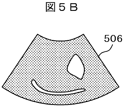
図4で示した処理フローにより超音波画像を高分解能化した例を図5A〜Dに示す。図5Aにおいて、画像502〜505は時間軸501に沿ってそれぞれ時刻t-3,t-2,t-1,tのタイミングで取得した超音波画像群である。図5Bの506は画像復元処理により図5Aの画像502〜505を用いて時刻tにおける超音波画像505を高分解能化した画像を示す。本例は超音波プローブ103から得られた画像データをスキャンコーバータ112によって扇型の画像に変換した超音波画像群を用いて処理をした例である(つまり,図2に示す装置構成における処理例である)。
An example in which the resolution of the ultrasonic image is increased by the processing flow shown in FIG. 4 is shown in FIGS. In FIG. 5A,
一方,図1に示す装置構成においても本実施例を適用することができる。この場合,図5Cに示すようなスキャンコンバータ前の超音波画像群507〜510から、図5Dに示すような高分解能のスキャンコンバータ前の超音波画像511を生成する。すなわち、図5A及びBを用いて説明したのと同様に、図5Cにおいて、画像507〜510は時間軸501に沿ってそれぞれ時刻t-3,t-2,t-1,tのタイミングで取得した超音波画像群である。図5Dの511は画像復元処理により図5Cの画像507〜510を用いて時刻tにおける超音波画像510を高分解能化した画像を示す。この高分解能化した超音波画像510に対してスキャンコンバータ112で座標変換処理や補間処理を行うことにより図5Bの扇形をした画像に変換され、表示部113の画面上に表示することができる。
On the other hand, this embodiment can also be applied to the apparatus configuration shown in FIG. In this case, a high-resolution
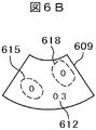
また,画像間の位置ずれ量を基に超音波画像の領域分割を行い,分割された領域毎に画像復元処理の重みパラメータを設定する実施例を図6A〜Eに示す。ここで,前記重みパラメータが大きな領域の画像ほど画像復元処理の結果に大きく反映されることを特徴とする。例えば,位置ずれ量が大きな箇所は,その周辺部位の形状が大きく変形している可能性が高く,前記変形を補正して画像復元処理を行うことが困難である場合がある。そのような場合においては,本発明により位置ずれ補正が困難な領域は前記重みパラメータが小さく設定され,その領域においては処理対象画像の画像データが支配的になる。すなわち,本発明により心臓等の動きが早い部位の観察においても画像復元処理の効果が出る領域のみを自動で抽出して高分解能化することができる。 Further, FIGS. 6A to 6E show an embodiment in which an ultrasonic image is divided into regions based on the amount of positional deviation between images, and a weight parameter for image restoration processing is set for each divided region. Here, as the weight parameter is larger, an image of a larger area is more greatly reflected in the result of the image restoration process. For example, a portion with a large amount of positional deviation is likely to have a large deformation in the shape of its peripheral portion, and it may be difficult to correct the deformation and perform image restoration processing. In such a case, the weight parameter is set to be small in an area where it is difficult to correct misalignment according to the present invention, and the image data of the processing target image is dominant in that area. That is, according to the present invention, it is possible to automatically extract only the region where the effect of the image restoration processing is obtained even in the observation of the fast moving part such as the heart, thereby increasing the resolution.
図6Aの602〜604は時間軸601に沿って撮像された超音波画像である。この場合,処理対象となる画像を超音波画像604とする。超音波画像604と603との位置ずれ量を算出した結果を図6Eの605に示し,位置ずれの方向と大きさを矢印615で示している。図6Eの606〜608は前記位置ずれ量を基に,3つの領域に分割した結果である。領域607は位置ずれがもっとも大きな領域で,領域606は位置ずれがもっとも小さな領域である。図6Bの609、図6Cの610及び図6Dの611は図6Eに示した領域分割結果606〜608を基に画像復元処理における重みパラメータを設定した結果である。
図6B乃至Dの位置ずれ量が小さな領域612〜614はそれぞれ0.3,0.3,0.4が設定されている。すなわちこのことは,画像復元処理において,図6B乃至Dの領域612〜614の画像はどれも同じように画像復元結果に反映されることを意味する。図6B乃至Dの位置ずれ量が大きな領域615〜617については,図6Dの領域617以外は重みパラメータがゼロと設定されている。すなわち図6Eの領域607の部分に関しては,画像復元処理において図6Dの領域617の画像のみを画像復元結果に反映させることを意味する。同様に,図6B乃至Dの領域618〜620も重みパラメータを設定されている。
ここで,重みパラメータを考慮した画像復元処理は,次に示す数式2を最小化することで行うことができる。
Here, the image restoration processing considering the weight parameter can be performed by minimizing the following
ここで,式中のWiはi番目の画像の重みパラメータをかける作用である。なお,領域分割に関しては上記のように位置ずれ量を基に自動で行うこともできるし,GUI上でユーザが指定した領域を用いても良い。 Here, Wi in the equation is an action of applying the weight parameter of the i-th image. Note that the area division can be automatically performed based on the positional deviation amount as described above, or an area specified by the user on the GUI may be used.
図17は、本実施例において、フレーム毎にスキャン条件を変更して取得した超音波画像群から画像復元処理を行って高分解能の超音波画像を生成し,それをリアルタイムに表示およびスキャン条件・画像復元処理パラメータを設定するGUIの例である。1701は超音波プローブにより撮像した超音波画像をリアルタイムに表示している。ボックス1702で撮像フレームレートを設定する。実際の撮像フレームレートは1703に表示している。ボックス1704〜1706で画像復元処理のパラメータを設定する。
FIG. 17 shows a high-resolution ultrasonic image generated by performing an image restoration process from an ultrasonic image group acquired by changing the scanning condition for each frame in this embodiment, and displaying it in real time. It is an example of GUI which sets an image restoration process parameter.
ボックス1704では画像復元処理後の出力画像のサイズを設定する。ボックス1705では画像復元処理に用いるフレーム画像枚数を指定する。ボックス1706ではスキャン方式を選択する。チェックボックス1707を選択すれば,フレーム毎にスキャン方位をインターレース方式で撮像する。また,チェックボックス1708を選択すれば,フレーム毎に超音波ビームの焦点距離を変化させながら撮像する。
In a box 1704, the size of the output image after the image restoration process is set. In a box 1705, the number of frame images used for image restoration processing is designated. In
画像復元処理のパラメータを設定のちに,ボタン1709を押すと画像復元処理が実行され,画像復元処理を施して高分解能化した画像および表示フレームレートが1710および1711にリアルタイムに表示される。 When the button 1709 is pressed after setting the parameters of the image restoration processing, the image restoration processing is executed, and the image and the display frame rate, which have been subjected to the image restoration processing and have a high resolution, are displayed in real time in 1710 and 1711.
本発明における画像復元処理の第2の実施例を図7のフローを用いて示す。
本例では,取得した超音波画像間の時間軸上の中間のフレーム画像を推定して表示することで,フレームレートを向上させる例である。すなわち,実施例1は空間分解能を向上させる処理であったが,本実施例では取得したフレーム画像間のフレーム画像を推定することにより時間方向の分解能を向上させる。これにより1フレームあたりのスキャン回数を低減させることなく(すなわち,画像の空間分解能を低下させることなく),フレームレートを向上させることができる。A second embodiment of the image restoration process according to the present invention will be described with reference to the flowchart of FIG.
In this example, the frame rate is improved by estimating and displaying an intermediate frame image on the time axis between acquired ultrasonic images. That is, the first embodiment is a process for improving the spatial resolution, but in this embodiment, the resolution in the time direction is improved by estimating the frame images between the acquired frame images. As a result, the frame rate can be improved without reducing the number of scans per frame (that is, without reducing the spatial resolution of the image).
まず,本処理フローにおいては,超音波画像の撮像時間の間隔H(取得撮像間隔)を取得する(S701)。取得撮像間隔Hは手動で与えても良いし要求フレームレート値から割り出してもよい。次に,超音波プローブ103を用いて被検体100を時系列に沿って,前記取得撮像間隔で複数撮像した超音波画像群X[t],X[t-1],X[t-2],…を取得する(S702)。取得したフレーム画像は記憶部123に格納される。続いて,実施例1と同様に画像間の位置ずれ量を算出する(S704)。続いて,前記超音波画像群および前記位置ずれ量を基に,前記処理対象画像を撮像したタイミングから前記取得撮像間隔より短い時間だけずれたタイミングで撮像したときに得られる超音波画像(中間フレーム画像)を推定して(S705),画面に出力する(S706)。終了判定(S707)の結果にしたがってS702〜706の処理を繰り返す。
First, in this processing flow, an ultrasonic imaging time interval H (acquired imaging interval) is acquired (S701). The acquired imaging interval H may be given manually or calculated from the required frame rate value. Next, a group of ultrasound images X [t], X [t-1], and X [t-2] obtained by capturing a plurality of images of the subject 100 in time series using the
図24に本処理において,出力フレームレートを指定した場合のフローを示す。まず,推定する中間フレーム画像の時間軸上のずれ量Δtをゼロに初期化する(S2400)。次に,超音波画像の撮像時間の間隔Hを取得する(S2401)。前記撮像時間の間隔Hは手動で入力した値を用いても良いし,入力されたフレームレートから割り出してもよい。次に,出力画像の時間間隔Kを取得する(S2402)。前記出力画像の時間間隔Kも前記Hと同様に,手動で入力した値を用いてもよいし,要求フレームレートから割り出しても良い。次に,前記撮像時間の間隔Hで超音波画像X[t]を取得し,時刻t=t+1とする(S2403)。取得した画像は記憶装置2410に格納される。 FIG. 24 shows a flow when the output frame rate is designated in this processing. First, the shift amount Δt on the time axis of the estimated intermediate frame image is initialized to zero (S2400). Next, the imaging time interval H of the ultrasonic image is acquired (S2401). The imaging time interval H may be a manually input value or may be calculated from the input frame rate. Next, the time interval K of the output image is acquired (S2402). Similarly to H, the time interval K of the output image may be a manually input value or may be calculated from the required frame rate. Next, an ultrasonic image X [t] is acquired at the imaging time interval H, and time t = t + 1 is set (S2403). The acquired image is stored in the storage device 2410.
次に,図7のフローと同様に画像間の位置ずれ量を算出し(S2404),中間フレーム画像X[t-Δt]を前記位置ずれ量および記憶部123に格納された超音波画像群を基に推定する(S2405)。このとき,もしΔt=0もしくはΔt=1の場合は中間フレーム画像を推定せずに,取得した超音波画像を出力することができる。次に,時間軸上のずれ量をΔt←Δt−K/Hと更新する(S2406)。
Next, as in the flow of FIG. 7, the amount of positional deviation between images is calculated (S2404), and the intermediate frame image X [t−Δt] is converted into the amount of positional deviation and the ultrasonic image group stored in the
処理終了判定(S2407)を経て,処理を継続するならば(Nの場合)時間軸上のずれ量Δtの符号を判定する(S2408)。もし,Δtが負の値であるならばΔt←Δt+1と値を更新(S2409)し,超音波画像X[t]取得ステップ(S2403)へ進む。そうでなければ,位置ずれ量算出ステップ(S2404)に進む。 If the process is to be continued through the process end determination (S2407) (in the case of N), the sign of the deviation amount Δt on the time axis is determined (S2408). If Δt is a negative value, the value is updated as Δt ← Δt + 1 (S2409), and the process proceeds to the ultrasonic image X [t] acquisition step (S2403). Otherwise, the process proceeds to the positional deviation amount calculation step (S2404).
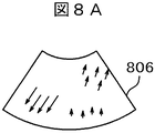
図8A乃至Cに本フローによる処理結果例を示す。図8Bの超音波画像802および803は時間軸801に沿って,取得撮像間隔Hで撮像された超音波画像である。一方、超音波画像804は、超音波画像802および803から,t-Δt(Δt≦1)で撮像した場合に得られる超音波画像を推定した画像である。超音波画像804の内部の805の領域内の線状の部位は,超音波画像802および803間で左上から右下方向に移動しているが,超音波画像804ではその中間の位置に前記部位が配置されるように推定されている。
8A to 8C show processing result examples according to this flow.
中間フレーム画像の推定方法としては,図8Aに示すように、まず時刻tと時刻t-1との位置ずれ量を算出する(806)。次に,前記位置ずれ量806から図8Cに示すような中間フレーム画像の時刻における位置ずれ量を推定する(807)。推定方法としては単純に算出した位置ずれ量806を線形補間して求めることができる。最後に,前記推定した位置ずれ量を基に図8Bに示す取得した超音波画像802および803の画素を張り合わせ,あるいは重みつき加算を行うことで中間フレーム画像804を生成することができる。
As an estimation method of the intermediate frame image, as shown in FIG. 8A, first, a positional deviation amount between time t and time t−1 is calculated (806). Next, the positional deviation amount at the time of the intermediate frame image as shown in FIG. 8C is estimated from the positional deviation amount 806 (807). As an estimation method, the simply calculated
図19は、本実施例において、撮像した超音波画像において,時間軸上の中間のフレーム画像を推定し,フレームレートを向上させた超音波画像を表示するGUIの例である。1901は超音波プローブにより撮像した超音波画像をリアルタイムに表示している。ボックス1902で撮像フレームレートを設定する。実際の撮像フレームレートは1903に表示している。ボックス1904で出力画像のフレームレートを設定する。ボタン1910を押すと本処理が開始される。1905は最も新しく取得したフレーム画像(tフレーム)で,1906はフレーム画像1905の一つ前に取得した画像(t-1フレーム)を示す。1907は1905および1906から推定した,時間軸上でちょうど中間フレームの画像(t-0.5フレーム)である。前記の処理を行ってフレームレートを向上させた画像を1908にフレームレート1909と共に表示する。
FIG. 19 illustrates an example of a GUI that displays an ultrasonic image with an improved frame rate by estimating an intermediate frame image on the time axis in the captured ultrasonic image in the present embodiment. Reference numeral 1901 displays an ultrasonic image captured by the ultrasonic probe in real time. An imaging frame rate is set in
本発明における画像復元処理の第3の実施例を図9のフローを用いて示す。本例では,超音波プローブのスキャン条件をフレーム毎に切り替えることにより,画像復元処理をより効果的に行う例である。すなわち,画像復元処理は複数フレーム間の画像情報を相補的に補間する処理であるため,画像復元処理に殆ど同じような画像群を入力しても高分解能化の効果は小さい。 A third embodiment of the image restoration process according to the present invention will be described with reference to the flowchart of FIG. In this example, the image restoration process is more effectively performed by switching the scanning condition of the ultrasonic probe for each frame. That is, since the image restoration process is a process of interpolating image information between a plurality of frames in a complementary manner, even if almost the same image group is input to the image restoration process, the effect of increasing the resolution is small.
それに対して,本実施例では超音波プローブを制御してスキャン条件が異なる超音波画像群を取得し,画像復元処理を行うことを特徴とする。つまり,スキャン条件を変更することにより,超音波画像群に相補的な情報を多分に含ませることが可能となり,画像復元処理による高分解能化の効果を向上させることができる。 On the other hand, the present embodiment is characterized in that an ultrasonic probe is controlled to acquire an ultrasonic image group having different scanning conditions, and image restoration processing is performed. That is, by changing the scanning conditions, it is possible to include a large amount of complementary information in the ultrasound image group, and the effect of increasing the resolution by the image restoration process can be improved.
本処理フローにおいては,まず超音波プローブのスキャン条件を予め用意していたスキャン条件群の中から一つ選択して設定する(S901)。選択可能なスキャン条件としては,フレーム毎に偶数番目のスキャン方位のみの取得,および奇数番目のスキャン方位のみの取得を交互に切り替えるインターレース方式を用いることができる。動きが小さな箇所においては前記インターレース方式で単純に2フレームの画像を重ね合わせるだけでも高分解能化が図れる。 In this processing flow, first, the scanning conditions for the ultrasonic probe are selected and set from a group of scanning conditions prepared in advance (S901). As a selectable scan condition, an interlace method in which acquisition of only even-numbered scan orientations and acquisition of only odd-numbered scan orientations are alternately switched for each frame can be used. In places where the movement is small, high resolution can be achieved by simply superimposing two frames of images using the interlace method.
一方,動きが大きな場合ではフレーム間のつなぎ目でジッタと呼ばれる位置ずれが発生する場合がある。このようなジッタに対しても,前記位置ずれ量を用いて補正処理を行うことが可能である。また,本方式は3フレーム以上の場合でのスキャン方位の切り替え,および合成も同様の要領で可能である。 On the other hand, when the motion is large, a positional shift called jitter may occur at the joint between frames. Even for such jitter, correction processing can be performed using the amount of positional deviation. In this method, the scan direction can be switched and combined in the same manner in the case of 3 frames or more.
また,別のスキャン方式としては,フレーム毎にスキャンの焦点距離を切り替える方式を用いることができる。すなわち,スキャンにおいて超音波ビームの焦点を特定の位置に絞ると,その箇所は鮮明に画像取得できるが,それ以外の箇所はぼやけてしまう。そこで,フレーム毎にスキャン焦点距離を変えて取得した超音波画像を合成することで,焦点があった画像領域を増やすことができる。 As another scanning method, a method of switching the focal length of scanning for each frame can be used. In other words, if the focal point of the ultrasonic beam is narrowed down to a specific position during scanning, the image can be clearly acquired at that location, but the other locations are blurred. Therefore, by combining the ultrasonic images acquired by changing the scan focal length for each frame, the focused image area can be increased.
続いて,超音波プローブ103を用いて被検体100を時系列に沿って,選択したスキャン条件で撮像した超音波画像X[t]を取得する(S902)。取得した超音波画像群X[t],X[t-1],…は記憶部123に格納される。続いて,画像復元処理を用いて前記超音波画像群から超音波画像X[t]の高分解能な超音波画像Y[t]を生成して(S904)表示する(S905)。なお,本実施例では1フレームあたりのスキャン回数を増やすわけではないため,フレームレートを低下させることなく画像の空間分解能を向上させることが可能である。
Subsequently, an ultrasonic image X [t] obtained by imaging the subject 100 with the selected scanning condition is acquired along the time series using the ultrasonic probe 103 (S902). The acquired ultrasonic image groups X [t], X [t−1],... Are stored in the
図10A乃至Cにスキャン方位を切り替える例および本処理フローの結果例を示す。本例はスキャン方位の異なる2枚のフレーム画像から1枚のフレーム画像を生成した例である。図10Aのスキャン方位1001−1〜1001−5は1フレーム目の超音波プローブ103から発した超音波ビームのスキャン方位を示し,スキャン方位1002−1〜1002−4は2フレーム目の超音波プローブ103から発した超音波ビームのスキャン方位を示す。図10Bの部分画像1003−1〜1003−5は1フレーム目のスキャンによって得られた画像データを示し,部分画像1004−1〜1004−4は2フレーム目のスキャンによって得られた画像データを示す。このように,両フレームの画像データを統合することで各フレームの画像情報を相補的に合成して方位方向の分解能が向上した超音波画像1007を取得することができる。
FIGS. 10A to 10C show an example of switching the scan direction and an example of the result of this processing flow. In this example, one frame image is generated from two frame images having different scan directions. In FIG. 10A, scan directions 1001-1 to 1001-5 indicate the scan directions of the ultrasonic beam emitted from the
超音波画像1007の生成には実施例1と同様に画像間の位置ずれ量を求めて画像復元処理を用いても良いし,単純に加算平均を行って生成してもよい。3フレーム目では1フレーム目と同じく,図10Aの矢印1001−1〜1001−5で示すスキャン方位に超音波ビームを発することで2フレーム目,3フレーム目で得られた画像データを統合して分解能が向上した超音波画像を生成できる。また,図10Bの超音波画像1007は、図2に示したシステム構成でスキャンコンバータ後の超音波画像で本処理を行っているが,図1に示したシステム構成を用いてスキャンコンバータ前の超音波画像で本処理を行っても良い。
The
図10Cの1008はスキャンコンバータ前の超音波画像で本処理を適用した例である。本例では,1フレーム目に部分画像1005−1〜1005−5の画像データを取得し,2フレーム目に部分画像1006−1〜1006−4の画像データを取得して,両画像データを合成して高分解能な超音波画像1008を生成している。また,本例では2フレームの場合で説明したが,3フレーム以上の場合も同じ要領で行うことができる。
図11に3フレームの例を示す。本例ではスキャン方位1101−1〜1101−3が1フレーム目のスキャン方位で,スキャン方位1102−1〜1102−3が2フレーム目のスキャン方位で,スキャン方位1103−1〜1103−3が3フレーム目のスキャン方位となっている。 FIG. 11 shows an example of 3 frames. In this example, the scan directions 1101-1 to 1101-3 are the scan directions of the first frame, the scan directions 1102-1 to 1102-3 are the scan directions of the second frame, and the scan directions 1103-1 to 1103-3 are three. It is the scan direction of the frame.
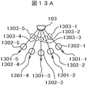
また,図10A乃至Cを用いて説明した実施例ではスキャン方位をフレーム毎に変更する場合であったが,フレーム毎にスキャンにおける超音波ビームの焦点距離を変更して超音波画像群を取得する例を、図13A及びBに示す。本例では,図13Aに示すようにスキャン方位1301−1〜1301−5の方位に超音波ビームを発するが,1フレーム目においては丸印1302−1〜1302−5の位置に焦点を合わせて超音波画像を取得し,2フレーム目においては丸印1303−1〜1303−5の位置に焦点を合わせて超音波画像を取得する。 In the embodiment described with reference to FIGS. 10A to 10C, the scan direction is changed for each frame. However, the ultrasonic image group is acquired by changing the focal length of the ultrasonic beam in the scan for each frame. An example is shown in FIGS. 13A and B. In this example, as shown in FIG. 13A, an ultrasonic beam is emitted in the directions of scan azimuths 1301-1 to 1301-5, but in the first frame, focusing is performed on the positions of circles 1302-1 to 1302-5. An ultrasonic image is acquired, and in the second frame, an ultrasonic image is acquired by focusing on the positions of circles 1303-1 to 1303-5.
すなわち,図13Bに示すような超音波画像のうち1フレーム目は超音波画像の下側の領域1305が鮮明になるが,上側の領域1306がぼやける。同様に2フレーム目は超音波画像の下側の領域1305がぼやけるが,上側の領域1306が鮮明になる。このように,超音波ビームはどこか一箇所に焦点を合わせると,それ以外がぼやけるという性質があり,通常,この焦点は画像全体が平均的に鮮明になるように中央付近に焦点が設定される。一方,本発明では積極的に焦点位置を変更して超音波画像を取得し,これらの複数の超音波画像を統合することで,画像全体の焦点のあった鮮明な超音波画像の取得が可能となる。
That is, in the first frame of the ultrasonic image as shown in FIG. 13B, the
また,図14A及びBに示すように、本処理はユーザが指定した領域に対してのみ適用することも可能である。図14Aの超音波画像1401で,1402はユーザが指定した領域(ROI)である。この場合,図14Bのスキャン方位1403で示すスキャン方位のように,超音波プローブ103を制御して図14AのROI1402にスキャン方位を集中させるように超音波画像を撮像することもできる。
また,本処理は,同時に二つの方位に超音波ビームを照射して信号を受信,あるいは一方の方位に超音波ビームを照射し信号を受信する前にもう一方の方位に超音波ビームを照射するマルチビーム方式と併用して適用することもできる。Further, as shown in FIGS. 14A and 14B, this processing can be applied only to an area designated by the user. In the
In addition, this processing irradiates signals in two directions at the same time and receives signals, or irradiates ultrasonic beams in one direction and irradiates ultrasonic beams in the other direction before receiving signals. It can also be applied in combination with the multi-beam method.
図18は、本実施例において、ユーザが指定した領域(ROI)を高分解能化して表示するGUIの例である。1801は超音波プローブにより撮像した超音波画像をリアルタイムに表示している。ボックス1802で撮像フレームレートを設定する。実際の撮像フレームレートは1803に表示している。1804はユーザがマウスクリック等で指定したROIである。ボックス1805〜1807で画像復元処理のパラメータを設定する。ボックス1805では画像復元処理による画像の拡大倍率を設定する。ボックス1806では画像復元処理に用いるフレーム画像枚数を指定する。ボックス1807はスキャン方式を選択する。ボタン1808を押すと1804のROI内のみに画像復元処理が実行され,画像復元処理を施して高分解能化した画像が1809に表示される。なお,指定したROIのみにスキャンを集中させて,ROIの画像のみを高分解能化して表示することもできる。
FIG. 18 shows an example of a GUI that displays a region (ROI) designated by the user with high resolution in this embodiment.
本発明における画像復元処理の第4の実施例を図15のフローを用いて示す。本例では,例えば心臓等の周期的な動きをおこなう被検体に対して,その周期情報を用いて超音波プローブを制御して超音波画像群を取得し,画像復元処理を用いて2周期以上の超音波画像群から,それよりも短い時間範囲(例えば,1周期分)の高分解能の超音波画像郡を生成する例である。すなわち,心臓等の部位は周期的な反復運動を行うため,周期上で同一の時間位相となる超音波画像は殆ど同じような画像が得られるが,実施例3で述べた理由と同様に,殆ど同じような画像を画像復元処理に多数入力しても高分解能化の効果はあまり望めない。 A fourth embodiment of the image restoration process according to the present invention will be described with reference to the flowchart of FIG. In this example, for an object that periodically moves, such as the heart, for example, an ultrasonic probe is acquired using the periodic information to acquire an ultrasonic image group, and two or more periods are acquired using image restoration processing. This is an example of generating a high-resolution ultrasonic image group in a shorter time range (for example, for one cycle) from the ultrasonic image group. That is, since a part such as the heart performs cyclic repetitive motion, an ultrasonic image having the same time phase on the period can obtain almost the same image, but for the reason described in the third embodiment, Even if many similar images are input to the image restoration process, the effect of increasing the resolution cannot be expected.
これに対して,本発明では前記対象画像と前記過去対象画像を撮像する際は,両画像を異なるスキャン条件に変更して撮像することにより,超音波画像群に相補的な情報を多分に含ませることができ,画像復元処理による効果を向上させることができる。 On the other hand, in the present invention, when capturing the target image and the past target image, complementary information is included in the ultrasound image group by changing both images to different scanning conditions. The effect of the image restoration process can be improved.
本処理フローにおいては,まず被検体100の動きの周期Tを取得する(S1501)。周期Tは手動で与えても良いし,被検体100をある程度の時間範囲で撮像して得た超音波画像群から自動で算出することもできる。次に,超音波プローブのスキャン条件を予め用意していたスキャン条件群の中から一つ選択して設定する(S1502)。選択可能なスキャン条件としては,実施例3の場合と同様に、スキャン方位,スキャン範囲,スキャン焦点距離などを変更することができる。続いて,超音波プローブ103を用いて被検体100を時系列に沿って,フレーム毎にスキャン条件を変えて2周期以上の超音波画像群を取得する(S1503)。
In this processing flow, first, the movement period T of the subject 100 is acquired (S1501). The period T may be given manually, or can be automatically calculated from a group of ultrasonic images obtained by imaging the subject 100 within a certain time range. Next, one scan condition for the ultrasonic probe is selected and set from a group of scan conditions prepared in advance (S1502). As selectable scan conditions, the scan direction, scan range, scan focal length, and the like can be changed as in the third embodiment. Subsequently, the
スキャン条件としては,スキャン方位,スキャン範囲,スキャン焦点距離などを変更することができる。取得した画像は記憶部123に格納される。スキャン条件の変更のタイミングとしては,1周期毎にスキャン条件を変更してもよいし,1周期分だけずれた超音波画像間のスキャン条件が異なるようにしさえすればフレーム毎にスキャン条件を変更してもよい。画像の撮像は終了判定(S1505)によって撮像が終了していない場合には、スキャン条件選択ステップ(S1502)と超音波画像取得ステップ(S1503)をループする。撮像終了後,前記超音波画像群を画像復元処理に入力して高分解能な超音波画像群を生成し(S1506),それを表示する(S1507)。
As the scanning condition, a scanning direction, a scanning range, a scanning focal length, and the like can be changed. The acquired image is stored in the
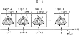
図16は図15のフローにより,周期的な動きを行う被検体に対して周期毎にスキャン方位を変更した例を示す。超音波画像1601−1は時刻tに取得したフレーム画像で,超音波画像1601−4は超音波画像1601−1より1周期だけ過去に取得したフレーム画像である。超音波画像1601−3及び1601−2はそれぞれ時刻t-T+1,t-T+2に取得したフレーム画像である。スキャン方位1602−1〜1602−4はそれぞれ超音波画像1601−1〜1601−4を取得したときのスキャン方位を示す。 FIG. 16 shows an example in which the scan azimuth is changed for each cycle with respect to the subject that periodically moves according to the flow of FIG. The ultrasonic image 1601-1 is a frame image acquired at time t, and the ultrasonic image 1601-4 is a frame image acquired in the past by one cycle from the ultrasonic image 1601-1. Ultrasonic images 1601-3 and 1601-2 are frame images acquired at times t-T + 1 and t-T + 2, respectively. Scan orientations 1602-1 to 1602-4 indicate scan orientations when ultrasonic images 1601-1 to 1601-4 are acquired, respectively.
図12Aは図15のフローにより,周期的な動きを行う被検体に対して周期毎にスキャン範囲を変更して画像を取得・合成した例である。スキャン方位1201−1〜1201−3は時刻tのスキャン方位で,スキャン方位1202−1〜1202−3はスキャン方位1201−1〜1201−3よりも1周期だけ過去のスキャン方位で,スキャン方位1203−1〜1203−3はスキャン方位1201−1〜1201−3よりも2周期だけ過去のスキャン方位である。 FIG. 12A is an example of acquiring and synthesizing an image by changing the scan range for each cycle for a subject that periodically moves according to the flow of FIG. 15. Scan azimuths 1201-1 to 1201-3 are scan azimuths at time t, scan azimuths 1202-1 to 1202-3 are scan azimuths past by one cycle from scan azimuths 1201-1 to 1201-3, and scan azimuths 1203 −1 to 1203-3 are scan azimuths past by two periods from the scan azimuths 1201-1 to 1201-3.
図12Bの部分画像1204−1はスキャン方位1201−1〜1201−3により得られた超音波画像で,部分画像1204−2はスキャン方位1202−1〜1202−3により得られた超音波画像で,部分画像1204−3はスキャン方位1203−1〜1203−3により得られた超音波画像である。 The partial image 1204-1 in FIG. 12B is an ultrasound image obtained by the scan orientations 1201-1 to 1201-3, and the partial image 1204-2 is an ultrasound image obtained by the scan orientations 1202-1 to 1202-3. , Partial images 1204-3 are ultrasonic images obtained by the scan directions 1203-1 to 1203-3.
部分画像1204−1〜1204−3を連結することで,1枚の高分解能な超音波画像1204を生成することができる。この画像の連結においては,各画像が重なる部分は加算平均をとってもよいし,画像の連結部分の境界がシームレスに繋がるように,前記境界付近をぼかしフィルタなどで補正処理を加えてもよい。
By connecting the partial images 1204-1 to 1204-3, one high-resolution
図20は、本実施例において、被検体の動きの周期を利用してスキャン条件を変更して撮像した超音波画像群から画像復元処理を行うGUIの例である。本実施例による処理は実施例1乃至3で説明したようなリアルタイム処理ではなく,一定の時間範囲を撮像した超音波画像群(入力超音波動画)から,高分解能の超音波動画をオフラインで生成する例である。 FIG. 20 is an example of a GUI that performs image restoration processing from a group of ultrasonic images picked up by changing scan conditions using the movement period of the subject in the present embodiment. The processing according to the present embodiment is not real-time processing as described in the first to third embodiments, but a high-resolution ultrasonic moving image is generated off-line from an ultrasonic image group (input ultrasonic moving image) obtained by imaging a certain time range. This is an example.
2001は処理対象となる超音波動画を示す。超音波動画2001はツールバー2002で再生,停止,再生位置の変更等を行いプレビューすることができる。2003〜2007は画像復元処理のパラメータを設定する項目である。
ボックス2003で出力画像のサイズを設定する。ボックス2004で被検体の動きの周期を設定する。前記周期は手動で与えても良いし,ボタン2008を押して入力超音波動画から自動で算出してもよい。ボックス2005で画像復元処理の出力画像の時間範囲を設定する。ボックス2006で画像復元処理に用いるフレーム画像の枚数を設定する。
In box 2003, the size of the output image is set. In the
ボックス2007ではスキャン方式を選択する。チェックボックス2008を選択すれば,フレーム毎にスキャン方位をインターレースに切り替えて撮像する。また,チェックボックス2009を選択すれば,フレーム毎にスキャン範囲を変化させながら撮像する。また,チェックボックス2010を選択すれば,フレーム毎に超音波ビームの焦点距離を変化させながら撮像する。画像復元処理のパラメータを設定した後に,ボタン2011を押すと画像復元処理が実行される。
In
2011は画像復元処理より出力された高分解能な超音波動画である。この動画はツールバー2012で再生,停止,再生位置の変更等を行いプレビューすることができる。また,画像2013〜2015は表示中の出力画像2010に対する画像復元処理への入力超音波画像群である。画像2014は表示中の出力画像2010の1周期だけ過去のフレーム画像で,画像2015は表示中の出力画像2010の2周期だけ過去のフレーム画像である。
2011 is a high-resolution ultrasonic moving image output from the image restoration processing. This moving image can be previewed by playing, stopping, changing the playback position, etc. on the toolbar 2012. In addition,
以上,本発明の実施例について述べてきたが,本発明は上述の実施例に限定されるものでは無く,変形して実施することが可能である。
(付記1)
以上説明したように、本発明は、超音波プローブを用いて超音波信号で試料をスキャンし試料からの反射波を受信した信号から得られる超音波画像を処理して試料の超音波画像を復元する方法であって、撮像して得た超音波画像を構成する一連のフレームの超音波画像の中からある時点のフレームの超音波画像と該ある時点よりも前の時点におけるフレームの超音波画像を抽出し、この抽出したある時点のフレームの超音波画像とある時点よりも前の時点におけるフレームの超音波画像との位置ずれ量を算出し、この算出した位置ずれ量の情報を用いて抽出したある時点のフレームの超音波画像と前記ある時点よりも前の時点におけるフレームの超音波画像との間の位置ずれを補正し、抽出したある時点のフレームの超音波画像とある時点よりも前の時点におけるフレームの超音波画像とを合成することにより1フレーム分の合成超音波画像を復元処理することを特徴とする超音波画像の画像復元方法である。
(付記2)
また、本発明は、ある時点のフレームの超音波画像と抽出したある時点よりも前の時点におけるフレームの超音波画像とは、超音波プローブを用いて超音波信号で試料をスキャンするときのスキャンの条件が異なる状態で得られたものであることを特徴とする付記1記載の超音波画像の画像復元方法である。
(付記3)
更に、本発明は、ある時点のフレームの超音波画像と抽出したある時点よりも前の時点におけるフレームの超音波画像とは、超音波プローブを用いて超音波信号で試料をスキャンするときのスキャンの方位又は焦点距離のうちの少なくとも一方が異なる状態でスキャンして得られたものであることを特徴とする付記1記載の超音波画像の画像復元方法である。
(付記4)
更に、本発明は、位置ずれを補正したある時点のフレームの超音波画像と該ある時点よりも前の時点におけるフレームの超音波画像とを合成することを、ある時点のフレームの超音波画像とこのある時点よりも前の時点におけるフレームの超音波画像とをそれぞれ局所的な領域に分割し,この局所的に分割された領域毎に異なる値の重みパラメータを設定し、重みが大きな領域ほど画像復元処理結果を大きく反映させることを特徴とする付記1記載の超音波画像の画像復元方法である。
(付記5)
更に、本発明は、位置ずれを補正した抽出したある時点のフレームの超音波画像とある時点よりも前の時点におけるフレームの超音波画像とを合成することによりある時点とある時点よりも前の時点との間の時点における1フレーム分の合成超音波画像を推定して作成することを特徴とする付記1記載の超音波画像の画像復元方法である。
(付記6)
更に、本発明は、試料は周期的な動作を行うものであり、撮像して得た画像は試料を周期の2倍以上の時間に亘って周期ごとの異なるスキャン条件でスキャンして得た超音波画像であり、ある時点のフレームの超音波画像とこのある時点よりも前の時点におけるフレームの超音波画像を抽出することが、ある時点のフレームの超音波画像とこのある時点よりも1周期前の時点におけるフレームの超音波画像を抽出することであることを特徴とする付記1記載の超音波画像の画像復元方法である。Although the embodiments of the present invention have been described above, the present invention is not limited to the above-described embodiments, and can be modified.
(Appendix 1)
As described above, the present invention restores an ultrasonic image of a sample by scanning the sample with an ultrasonic signal using an ultrasonic probe and processing an ultrasonic image obtained from the signal received from the reflected wave from the sample. An ultrasonic image of a frame at a certain point in time and an ultrasonic image of a frame at a point before the certain point in time from among a series of ultrasonic images constituting an ultrasonic image obtained by imaging Is extracted, and the amount of positional deviation between the extracted ultrasonic image of the frame at a certain time point and the ultrasonic image of the frame at a time point before the certain time point is calculated, and extraction is performed using the information on the calculated positional deviation amount. The positional deviation between the ultrasonic image of the frame at a certain time point and the ultrasonic image of the frame at the time point before the certain time point is corrected, and the extracted ultrasonic image of the frame at the certain time point and the certain time point are corrected. Also image restoration method of an ultrasound image, characterized in that an ultrasonic image of a frame at a time prior to the restoration process a composite ultrasound image for one frame by combining.
(Appendix 2)
Further, the present invention relates to an ultrasonic image of a frame at a certain time point and an ultrasonic image of a frame at a time point before the extracted certain time point when scanning a sample with an ultrasonic signal using an ultrasonic probe. The method of restoring an ultrasonic image according to
(Appendix 3)
Further, according to the present invention, an ultrasonic image of a frame at a certain time point and an ultrasonic image of a frame at a time point before the extracted certain time point are scanned when a sample is scanned with an ultrasonic signal using an ultrasonic probe. The ultrasonic image restoration method according to
(Appendix 4)
Furthermore, the present invention combines the ultrasonic image of a frame at a certain point in time with the positional deviation corrected and the ultrasonic image of the frame at a point in time before the certain point of time into an ultrasonic image of the frame at a certain point of time. The ultrasonic image of the frame at a time point before a certain time point is divided into local areas, and different weight parameters are set for each of the locally divided areas. The ultrasonic image restoration method according to
(Appendix 5)
Furthermore, the present invention is a method in which an ultrasonic image of a frame at a certain time point that has been corrected for positional deviation and an ultrasonic image of a frame at a time point before the certain time point are combined to combine the ultrasonic image of the frame at a certain time point before the certain time point. The method of restoring an ultrasonic image according to
(Appendix 6)
Furthermore, according to the present invention, the sample performs a periodic operation, and an image obtained by imaging is a super image obtained by scanning the sample under a different scanning condition for each cycle over a time that is twice or more of the cycle. Extracting an ultrasonic image of a frame at a certain time point and an ultrasonic image of a frame at a time point before the certain time point is one period from the ultrasonic image of the frame at a certain time point and the certain time point. The method of restoring an ultrasonic image according to
本発明は,超音波を被検体に送受信して画像を取得する超音波診断装置に利用でき,特に、取得した画像に対して画像処理によって,空間分解能あるいは時間分解能を向上させる処理を施す超音波画像の画像復元方法を備えた超音波診断装置に利用できる。 INDUSTRIAL APPLICABILITY The present invention can be used in an ultrasonic diagnostic apparatus that acquires an image by transmitting / receiving ultrasonic waves to / from a subject. In particular, an ultrasonic wave that performs processing for improving spatial resolution or temporal resolution by image processing on an acquired image. It can be used for an ultrasonic diagnostic apparatus equipped with an image restoration method.
100…被検体 101…超音波診断装置 102…駆動回路部 103…超音波プローブ 104…受診回路部 105…画像生成部 106…画像処理部 112…スキャンコンバータ 113…表示部 120…制御・記憶・処理部 121…入力部 122…制御部 123…記憶部 124…処理部。
DESCRIPTION OF
Claims (15)
信号から得られる超音波画像を処理して該試料の超音波画像を復元する方法であって、
該撮像して得た超音波画像を構成する一連のフレームの超音波画像の中からある時点の
フレームの超音波画像と該ある時点よりも前の時点におけるフレームの超音波画像を抽出
し、
該抽出した前記ある時点のフレームの超音波画像と前記ある時点よりも前の時点におけ
るフレームの超音波画像との位置ずれ量を算出し、
該算出した位置ずれ量の情報を用いて前記抽出したある時点のフレームの超音波画像と
前記ある時点よりも前の時点におけるフレームの超音波画像との間の位置ずれを補正し、
前記抽出したある時点のフレームの超音波画像と前記ある時点よりも前の時点におけるフレームの超音波画像とを合成することにより1フレーム分の合成超音波画像を復元処理し、
前記位置ずれを補正した前記ある時点のフレームの超音波画像と該ある時点よりも前の
時点におけるフレームの超音波画像とを合成することを、
前記ある時点のフレームの超音波画像と該ある時点よりも前の時点におけるフレームの超音波画像とをそれぞれ局所的な領域に分割し,
該局所的に分割された領域毎に異なる値の重みパラメータを設定し、
前記重みが大きな領域ほど画像復元処理結果を大きく反映させる
ことを特徴とする超音波画像の画像復元方法。 A method of restoring an ultrasound image of a sample by scanning the sample with an ultrasound signal using an ultrasound probe and processing an ultrasound image obtained from a signal received from a reflected wave from the sample,
Extracting an ultrasonic image of a frame at a certain time point and an ultrasonic image of a frame at a time point before the certain time point from among a series of ultrasonic images constituting the ultrasonic image obtained by the imaging;
Calculating a positional deviation amount between the extracted ultrasonic image of the frame at the certain time point and the ultrasonic image of the frame at the time point before the certain time point;
Correcting the positional deviation between the extracted ultrasonic image of the frame at a certain point in time using the calculated positional deviation amount information and the ultrasonic image of the frame at a point in time before the certain point of time,
The synthesized ultrasonic image for one frame is restored by combining the extracted ultrasonic image of the frame at a certain time point and the ultrasonic image of the frame at a time point before the certain time point ,
An ultrasonic image of the frame at a certain point in time when the positional deviation is corrected, and a frame before the certain point in time.
Combining the ultrasound image of the frame at the time point,
Dividing the ultrasonic image of the frame at a certain time point and the ultrasonic image of the frame at a time point before the certain time point into local regions,
Set different weight parameters for each locally divided region,
An ultrasonic image restoration method, wherein the larger the weight is, the larger the image restoration processing result is reflected .
フレームの超音波画像とは、前記超音波プローブを用いて超音波信号で試料をスキャンす
るときのスキャンの条件が異なる状態で得られたものであることを特徴とする請求項1記
載の超音波画像の画像復元方法。 The ultrasonic image of the frame at the certain time point and the ultrasonic image of the frame at the time point before the extracted certain time point are the scanning conditions when the sample is scanned with an ultrasonic signal using the ultrasonic probe. 2. The method of restoring an ultrasonic image according to claim 1, wherein the image is obtained in a different state.
フレームの超音波画像とは、前記超音波プローブを用いて超音波信号で試料をスキャンす
るときのスキャンの方位又は焦点距離のうちの少なくとも一方が異なる状態でスキャンし
て得られたものであることを特徴とする請求項1記載の超音波画像の画像復元方法。 The ultrasonic image of the frame at the certain time point and the ultrasonic image of the frame at the time point before the extracted certain time point are the azimuth of the scan when the sample is scanned with the ultrasonic signal using the ultrasonic probe or 2. The ultrasonic image restoration method according to claim 1, wherein at least one of the focal lengths is obtained by scanning in a different state.
りも前の時点におけるフレームの超音波画像とを合成することにより前記ある時点と前記
ある時点よりも前の時点との間の時点における1フレーム分の合成超音波画像を推定して
作成することを特徴とする請求項1記載の超音波画像の画像復元方法。 By synthesizing the extracted ultrasonic image of the frame at a certain time point corrected for the positional deviation and the ultrasonic image of the frame at a time point before the certain time point, the certain time point and the time point before the certain time point The method of restoring an ultrasonic image according to claim 1, wherein a synthetic ultrasonic image for one frame at a time point between and is estimated and created.
期の2倍以上の時間に亘って前記周期ごとの異なるスキャン条件でスキャンして得た超音
波画像であり、
前記ある時点のフレームの超音波画像と該ある時点よりも前の時点におけるフレームの
超音波画像を抽出することが、前記ある時点のフレームの超音波画像と該ある時点よりも
1周期前の時点におけるフレームの超音波画像を抽出することであることを特徴とする請
求項1記載の超音波画像の画像復元方法。 The sample performs a periodic operation, and the image obtained by imaging is an ultrasonic wave obtained by scanning the sample under a different scanning condition for each cycle over a time that is twice or more of the cycle. Image
Extracting an ultrasonic image of a frame at a certain time point and an ultrasonic image of a frame at a time point before the certain time point is an ultrasonic image of the frame at the certain time point and a time point one cycle before the certain time point 2. The method of restoring an ultrasonic image according to claim 1, wherein an ultrasonic image of the frame is extracted.
る受信回路手段と、
該受信回路手段で受信した反射波信号から超音波画像を生成する画像生成手段と、
該画像生成手段で生成した超音波画像を復元処理する画像処理手段と、
該画像処理手段で復元処理した超音波画像を画面上に表示する表示手段と
を有し、
前記画像処理手段は、前記画像生成手段で生成した超音波画像を構成する一連のフレームの超音波画像の中からある時点のフレームの超音波画像と該ある時点よりも前の時点におけるフレームの超音波画像を抽出し、該抽出した前記ある時点のフレームの超音
波画像と前記ある時点よりも前の時点におけるフレームの超音波画像との位置ずれ量を算
出し、該算出した位置ずれ量の情報を用いて前記抽出したある時点のフレームの超音波画
像と前記ある時点よりも前の時点におけるフレームの超音波画像との間の位置ずれを補正
し、該位置ずれを補正した前記抽出したある時点のフレームの超音波画像と前記ある時点
よりも前の時点におけるフレームの超音波画像とを合成することにより1フレーム分の合
成超音波画像を復元処理し、
前記画像処理手段は、さらに、前記位置ずれを補正した前記ある時点のフレームの超音波画像と該ある時点よりも前の時点におけるフレームの超音波画像とを合成することを、前記ある時点のフレームの超音波画像と該ある時点よりも前の時点におけるフレームの超音波画像とをそれぞれ局所的な領域に分割し,該局所的に分割された領域毎に異なる値の重みパラメータを設定し、前記重みが大きな領域ほど画像復元処理結果を大きく反映させることを特徴とする超音波画像の画像復元装置。 Receiving circuit means for receiving a reflected wave signal obtained by scanning a sample with an ultrasonic probe and receiving a reflected wave from the sample;
Image generating means for generating an ultrasonic image from the reflected wave signal received by the receiving circuit means;
Image processing means for restoring the ultrasonic image generated by the image generating means;
Display means for displaying on the screen the ultrasonic image restored by the image processing means,
The image processing means includes an ultrasonic image of a frame at a certain point in time from a series of ultrasonic images constituting the ultrasonic image generated by the image generating unit, and an ultrasonic of a frame at a time point before the certain point. A sound wave image is extracted, a positional deviation amount between the extracted ultrasonic image of the frame at the certain time point and the ultrasonic image of the frame at a time point before the certain time point is calculated, and information on the calculated positional deviation amount Is used to correct the positional deviation between the extracted ultrasonic image of the frame at a certain time point and the ultrasonic image of the frame at a time point before the certain time point, and the extracted certain time point after correcting the positional deviation. A composite ultrasonic image for one frame is restored by combining the ultrasonic image of the frame and the ultrasonic image of the frame at a time point before the certain time point ,
The image processing means further synthesizes the ultrasonic image of the frame at the certain time point corrected for the positional deviation and the ultrasonic image of the frame at the time point before the certain time point into the frame at the certain time point. Each of the ultrasonic image of the frame and the ultrasonic image of the frame at a time point earlier than the certain time point are each divided into local regions, and different weight parameters are set for each of the locally divided regions, An ultrasonic image restoration apparatus characterized in that an image restoration processing result is more largely reflected in a region having a larger weight .
時点よりも前の時点におけるフレームの超音波画像とは、前記超音波プローブを用いて超
音波信号で試料をスキャンするときのスキャンの条件が異なる状態で得られたものである
ことを特徴とする請求項6記載の超音波画像の画像復元装置。 The ultrasonic image of the frame at a certain time point to be processed by the image processing means and the ultrasonic image of the frame at a time point before the extracted certain time point are scanned with an ultrasonic signal using the ultrasonic probe. The ultrasonic image restoration apparatus according to claim 6 , wherein the scanning conditions are obtained in different states.
時点よりも前の時点におけるフレームの超音波画像とは、前記超音波プローブを用いて超
音波信号で試料をスキャンするときのスキャンの方位又は焦点距離のうちの少なくとも一
方が異なる状態でスキャンして得られたものであることを特徴とする請求項6記載の超音
波画像の画像復元装置。 The ultrasonic image of the frame at a certain time point to be processed by the image processing means and the ultrasonic image of the frame at a time point before the extracted certain time point are scanned with an ultrasonic signal using the ultrasonic probe. The ultrasonic image restoration apparatus according to claim 6 , wherein the image restoration apparatus is obtained by scanning in a state where at least one of a scanning direction or a focal length is different.
波画像と前記ある時点よりも前の時点におけるフレームの超音波画像とを合成することに
より前記ある時点と前記ある時点よりも前の時点との間の時点における1フレーム分の合
成超音波画像を推定して作成することを特徴とする請求項6記載の超音波画像の画像復元
装置。 The image processing means synthesizes the extracted ultrasonic image of the frame at a certain time point corrected for the positional deviation and the ultrasonic image of the frame at a time point before the certain time point, and the certain time point. The ultrasonic image restoration apparatus according to claim 6, wherein a synthetic ultrasonic image for one frame at a time point before a time point is estimated and created.
前記試料を前記周期の2倍以上の時間に亘って前記周期ごとの異なるスキャン条件でスキ
ャンして得た超音波画像であり、前記画像処理手段において、前記ある時点のフレームの
超音波画像と該ある時点よりも前の時点におけるフレームの超音波画像を抽出することが
、前記ある時点のフレームの超音波画像と該ある時点よりも1周期前の時点におけるフレ
ームの超音波画像を抽出することであることを特徴とする請求項6記載の超音波画像の画
像復元装置。 The sample performs a periodic operation, and an image obtained by imaging with the ultrasonic probe is obtained by scanning the sample under a different scanning condition for each cycle over a time that is twice or more of the cycle. In the obtained ultrasonic image, the image processing means extracts the ultrasonic image of the frame at the certain time point and the ultrasonic image of the frame at the time point before the certain time point. 7. The ultrasonic image restoration apparatus according to claim 6 , wherein an ultrasonic image and an ultrasonic image of a frame at a time point one cycle before the certain time point are extracted.
前記超音波プローブで受信した反射波信号を処理して超音波画像を生成する超音波画像
処理部と、
を備えた超音波診断装置であって、
前記超音波画像処理部は、
前記反射波信号から超音波画像を生成する画像生成手段と、
該画像生成手段で生成した超音波画像を復元処理する画像処理手段とを有し、
前記画像処理手段は、前記画像生成手段で生成した超音波画像を構成する一連のフレームの超音波画像の中からある時点のフレームの超音波画像と該ある時点よりも前の時点におけるフレームの超音波画像を抽出し、該抽出した前記ある時点のフレームの超音波画像と前記ある時点よりも前の時点におけるフレームの超音波画像との位置ずれ量を算出し、該算出した位置ずれ量の情報を用いて前記抽出したある時点のフレームの超音波画像と前記ある時点よりも前の時点におけるフレームの超音波画像との間の位置ずれを補正し、前記抽出したある時点のフレームの超音波画像と前記ある時点よりも前の時点におけるフレームの超音波画像とを合成することにより1フレーム分の合成超音波画像を復元処理し、
前記画像処理手段は、さらに、前記位置ずれを補正した前記ある時点のフレームの超音波画像と該ある時点よりも前の時点におけるフレームの超音波画像とを合成することを、前記ある時点のフレームの超音波画像と該ある時点よりも前の時点におけるフレームの超音波画像とをそれぞれ局所的な領域に分割し,該局所的に分割された領域毎に異なる値の重みパラメータを設定し、前記重みが大きな領域ほど画像復元処理結果を大きく反映させることを特徴とする超音波診断装置。 An ultrasonic probe that scans a sample with an ultrasonic signal and receives a reflected wave from the sample;
An ultrasonic image processing unit that generates an ultrasonic image by processing a reflected wave signal received by the ultrasonic probe;
An ultrasonic diagnostic apparatus comprising:
The ultrasonic image processing unit
Image generating means for generating an ultrasonic image from the reflected wave signal;
Image processing means for restoring the ultrasonic image generated by the image generation means,
The image processing means includes an ultrasonic image of a frame at a certain point in time from a series of ultrasonic images constituting the ultrasonic image generated by the image generating unit, and an ultrasonic of a frame at a time point before the certain point. A sound wave image is extracted, a positional deviation amount between the extracted ultrasonic image of the frame at the certain time point and the ultrasonic image of the frame at a time point before the certain time point is calculated, and information on the calculated positional deviation amount Is used to correct the positional deviation between the extracted ultrasonic image of the frame at a certain time point and the ultrasonic image of the frame at the time point before the certain time point, and the extracted ultrasonic image of the frame at the certain time point And a composite ultrasonic image of one frame by combining the ultrasonic image of the frame at a time point before the certain time point ,
The image processing means further synthesizes the ultrasonic image of the frame at the certain time point corrected for the positional deviation and the ultrasonic image of the frame at the time point before the certain time point into the frame at the certain time point. Each of the ultrasonic image of the frame and the ultrasonic image of the frame at a time point earlier than the certain time point are each divided into local regions, and different weight parameters are set for each of the locally divided regions, An ultrasonic diagnostic apparatus characterized in that an image restoration processing result is reflected more greatly in a region having a greater weight .
時点よりも前の時点におけるフレームの超音波画像とは、前記超音波プローブを用いて超
音波信号で試料をスキャンするときのスキャンの条件が異なる状態で得られたものである
ことを特徴とする請求項11記載の超音波診断装置。 The ultrasonic image of the frame at a certain time point to be processed by the image processing means and the ultrasonic image of the frame at a time point before the extracted certain time point are scanned with an ultrasonic signal using the ultrasonic probe. 12. The ultrasonic diagnostic apparatus according to claim 11, wherein scanning conditions are obtained in different states.
時点よりも前の時点におけるフレームの超音波画像とは、前記超音波プローブを用いて超
音波信号で試料をスキャンするときのスキャンの方位又は焦点距離のうちの少なくとも一
方が異なる状態でスキャンして得られたものであることを特徴とする請求項11記載の超
音波診断装置。 The ultrasonic image of the frame at a certain time point to be processed by the image processing means and the ultrasonic image of the frame at a time point before the extracted certain time point are scanned with an ultrasonic signal using the ultrasonic probe. The ultrasonic diagnostic apparatus according to claim 11, wherein the ultrasonic diagnostic apparatus is obtained by scanning in a state where at least one of a scanning direction or a focal length is different.
波画像と前記ある時点よりも前の時点におけるフレームの超音波画像とを合成することに
より前記ある時点と前記ある時点よりも前の時点との間の時点における1フレーム分の合
成超音波画像を推定して作成することを特徴とする請求項11記載の超音波診断装置。 The image processing means synthesizes the extracted ultrasonic image of the frame at a certain time point corrected for the positional deviation and the ultrasonic image of the frame at a time point before the certain time point, and the certain time point. The ultrasonic diagnostic apparatus according to claim 11, wherein a synthetic ultrasonic image for one frame at a time point before a time point is estimated and created.
前記試料を前記周期の2倍以上の時間に亘って前記周期ごとの異なるスキャン条件でスキ
ャンして得た超音波画像であり、
前記画像処理手段は、前記ある時点のフレームの超音波画像と該ある時点よりも前の時
点におけるフレームの超音波画像を抽出することが、前記ある時点のフレームの超音波画
像と該ある時点よりも1周期前の時点におけるフレームの超音波画像を抽出することであ
ることを特徴とする請求項11記載の超音波診断装置。 The sample performs a periodic operation, and an image obtained by imaging with the ultrasonic probe is obtained by scanning the sample under a different scanning condition for each cycle over a time that is twice or more of the cycle. It is the obtained ultrasound image,
The image processing means extracts the ultrasonic image of the frame at the certain time point and the ultrasonic image of the frame at the time point before the certain time point, based on the ultrasonic image of the frame at the certain time point and the certain time point. The ultrasonic diagnostic apparatus according to claim 11, wherein an ultrasonic image of a frame at a time point one cycle before is extracted.
Priority Applications (1)
| Application Number | Priority Date | Filing Date | Title |
|---|---|---|---|
| JP2012524480A JP5649083B2 (en) | 2010-07-14 | 2011-05-18 | Image restoration method and apparatus for ultrasonic image, and ultrasonic diagnostic apparatus |
Applications Claiming Priority (4)
| Application Number | Priority Date | Filing Date | Title |
|---|---|---|---|
| JP2010159771 | 2010-07-14 | ||
| JP2010159771 | 2010-07-14 | ||
| PCT/JP2011/061436 WO2012008217A1 (en) | 2010-07-14 | 2011-05-18 | Ultrasound image reconstruction method, device therefor and ultrasound diagnostic device |
| JP2012524480A JP5649083B2 (en) | 2010-07-14 | 2011-05-18 | Image restoration method and apparatus for ultrasonic image, and ultrasonic diagnostic apparatus |
Related Child Applications (1)
| Application Number | Title | Priority Date | Filing Date |
|---|---|---|---|
| JP2014085301A Division JP5859595B2 (en) | 2010-07-14 | 2014-04-17 | Image restoration method and apparatus for ultrasonic image, and ultrasonic diagnostic apparatus |
Publications (2)
| Publication Number | Publication Date |
|---|---|
| JPWO2012008217A1 JPWO2012008217A1 (en) | 2013-09-05 |
| JP5649083B2 true JP5649083B2 (en) | 2015-01-07 |
Family
ID=45469228
Family Applications (3)
| Application Number | Title | Priority Date | Filing Date |
|---|---|---|---|
| JP2012524480A Expired - Fee Related JP5649083B2 (en) | 2010-07-14 | 2011-05-18 | Image restoration method and apparatus for ultrasonic image, and ultrasonic diagnostic apparatus |
| JP2014085301A Expired - Fee Related JP5859595B2 (en) | 2010-07-14 | 2014-04-17 | Image restoration method and apparatus for ultrasonic image, and ultrasonic diagnostic apparatus |
| JP2015098110A Active JP5954806B2 (en) | 2010-07-14 | 2015-05-13 | Method for generating intermediate image of ultrasonic image and ultrasonic diagnostic apparatus |
Family Applications After (2)
| Application Number | Title | Priority Date | Filing Date |
|---|---|---|---|
| JP2014085301A Expired - Fee Related JP5859595B2 (en) | 2010-07-14 | 2014-04-17 | Image restoration method and apparatus for ultrasonic image, and ultrasonic diagnostic apparatus |
| JP2015098110A Active JP5954806B2 (en) | 2010-07-14 | 2015-05-13 | Method for generating intermediate image of ultrasonic image and ultrasonic diagnostic apparatus |
Country Status (3)
| Country | Link |
|---|---|
| US (2) | US20130090560A1 (en) |
| JP (3) | JP5649083B2 (en) |
| WO (1) | WO2012008217A1 (en) |
Families Citing this family (19)
| Publication number | Priority date | Publication date | Assignee | Title |
|---|---|---|---|---|
| WO2013111813A1 (en) * | 2012-01-27 | 2013-08-01 | 株式会社 東芝 | Medical image processing device |
| WO2013150917A1 (en) * | 2012-04-02 | 2013-10-10 | 日立アロカメディカル株式会社 | Ultrasound diagnostic device and ultrasound image super-resolution image generation method |
| CN105451662B (en) * | 2013-08-09 | 2019-03-01 | 皇家飞利浦有限公司 | The method and system shown for medical imaging and information |
| EP3235437A4 (en) * | 2014-12-19 | 2018-09-12 | Olympus Corporation | Ultrasonic observation device |
| JP6507731B2 (en) * | 2015-03-10 | 2019-05-08 | 富士通株式会社 | Interpolated image generation apparatus, interpolated image generation method, and computer program for interpolated image generation |
| JP5985007B1 (en) * | 2015-06-02 | 2016-09-06 | 株式会社日立製作所 | Ultrasonic diagnostic equipment |
| US9824442B2 (en) * | 2015-08-20 | 2017-11-21 | Siemens Medical Solutions Usa, Inc. | View direction adaptive volume ultrasound imaging |
| JP6597070B2 (en) * | 2015-09-02 | 2019-10-30 | セイコーエプソン株式会社 | Density unevenness correction method and printing apparatus |
| US10709421B2 (en) * | 2016-02-10 | 2020-07-14 | Canon Medical Systems Corporation | Ultrasound diagnostic apparatus |
| WO2018052093A1 (en) | 2016-09-14 | 2018-03-22 | 富士フイルム株式会社 | Photoacoustic image generation apparatus |
| EP3764910B1 (en) * | 2018-03-13 | 2023-11-15 | Verathon, Inc. | Generalized interlaced scanning with an ultrasound probe |
| CN111093521B (en) * | 2018-04-13 | 2022-06-17 | 深圳迈瑞生物医疗电子股份有限公司 | Ultrasonic imaging method and ultrasonic imaging apparatus |
| CN111182219B (en) * | 2020-01-08 | 2023-04-07 | 腾讯科技(深圳)有限公司 | Image processing method, device, server and storage medium |
| US11497479B2 (en) | 2020-05-09 | 2022-11-15 | Clarius Mobile Health Corp. | Method and system for controlling settings of an ultrasound scanner |
| JP7233792B2 (en) * | 2020-11-30 | 2023-03-07 | 株式会社Lily MedTech | Diagnostic imaging device, diagnostic imaging method, program, and method for generating training data for machine learning |
| CN113538665B (en) * | 2021-07-21 | 2024-02-02 | 无锡艾米特智能医疗科技有限公司 | Organ three-dimensional image reconstruction compensation method |
| CN113616945B (en) * | 2021-08-13 | 2024-03-08 | 湖北美睦恩医疗设备有限公司 | Detection method based on focused ultrasonic image recognition and beauty and body-building device |
| WO2023149515A1 (en) * | 2022-02-04 | 2023-08-10 | アイメジャー株式会社 | Three-dimensional object image scanner |
| CN117503203B (en) * | 2024-01-03 | 2024-03-22 | 之江实验室 | Phase aberration correction method and system for ultrasonic ring array imaging |
Citations (5)
| Publication number | Priority date | Publication date | Assignee | Title |
|---|---|---|---|---|
| JP2002526225A (en) * | 1998-10-01 | 2002-08-20 | コーニンクレッカ フィリップス エレクトロニクス エヌ ヴィ | Ultrasonic diagnostic imaging system that performs spatial synthesis with blur correction |
| JP2002526226A (en) * | 1998-10-01 | 2002-08-20 | コーニンクレッカ フィリップス エレクトロニクス エヌ ヴィ | Method for correcting blurring of spatially synthesized ultrasonic diagnostic images |
| JP2003061955A (en) * | 2001-08-30 | 2003-03-04 | Aloka Co Ltd | Ultrasonic diagnostic equipment |
| WO2007097108A1 (en) * | 2006-02-22 | 2007-08-30 | Hitachi Medical Corporation | Ultrasonic diagnostic equipment |
| JP2009039428A (en) * | 2007-08-10 | 2009-02-26 | Panasonic Corp | Ultrasonic diagnostic apparatus |
Family Cites Families (12)
| Publication number | Priority date | Publication date | Assignee | Title |
|---|---|---|---|---|
| JP3094238B2 (en) | 1991-02-21 | 2000-10-03 | 株式会社日立メディコ | Ultrasound diagnostic equipment |
| JP3264963B2 (en) | 1992-02-12 | 2002-03-11 | ジーイー横河メディカルシステム株式会社 | Ultrasound diagnostic equipment |
| JPH08307771A (en) | 1995-05-02 | 1996-11-22 | Toshiba Corp | Motion area detection circuit, noise reducing filter using this motion area detection circuit and x-ray radiographing device |
| US6210328B1 (en) | 1998-10-01 | 2001-04-03 | Atl Ultrasound | Ultrasonic diagnostic imaging system with variable spatial compounding |
| US20040225221A1 (en) * | 2003-05-06 | 2004-11-11 | Olsson Lars Jonas | Diagnostic ultrasound imaging system with adaptive persistence |
| US7492967B2 (en) | 2003-09-24 | 2009-02-17 | Kabushiki Kaisha Toshiba | Super-resolution processor and medical diagnostic imaging apparatus |
| JP4519434B2 (en) | 2003-09-24 | 2010-08-04 | 株式会社東芝 | Super-resolution processing apparatus and medical image diagnostic apparatus |
| CN101179998B (en) | 2005-05-20 | 2010-12-08 | 株式会社日立医药 | Image diagnosing device |
| JP4473779B2 (en) * | 2005-05-23 | 2010-06-02 | 株式会社東芝 | Ultrasonic diagnostic apparatus and image processing method thereof |
| JP5331313B2 (en) * | 2007-05-24 | 2013-10-30 | 株式会社日立メディコ | Ultrasonic diagnostic equipment |
| JP2010057010A (en) | 2008-08-29 | 2010-03-11 | Sharp Corp | Image display device |
| WO2010125789A1 (en) * | 2009-04-28 | 2010-11-04 | 株式会社日立メディコ | Method for improving image quality of ultrasonic image, ultrasonic diagnosis device, and program for improving image quality |
-
2011
- 2011-05-18 JP JP2012524480A patent/JP5649083B2/en not_active Expired - Fee Related
- 2011-05-18 WO PCT/JP2011/061436 patent/WO2012008217A1/en active Application Filing
- 2011-05-18 US US13/703,961 patent/US20130090560A1/en not_active Abandoned
-
2014
- 2014-04-17 JP JP2014085301A patent/JP5859595B2/en not_active Expired - Fee Related
-
2015
- 2015-05-13 JP JP2015098110A patent/JP5954806B2/en active Active
- 2015-06-15 US US14/739,387 patent/US9408591B2/en active Active
Patent Citations (5)
| Publication number | Priority date | Publication date | Assignee | Title |
|---|---|---|---|---|
| JP2002526225A (en) * | 1998-10-01 | 2002-08-20 | コーニンクレッカ フィリップス エレクトロニクス エヌ ヴィ | Ultrasonic diagnostic imaging system that performs spatial synthesis with blur correction |
| JP2002526226A (en) * | 1998-10-01 | 2002-08-20 | コーニンクレッカ フィリップス エレクトロニクス エヌ ヴィ | Method for correcting blurring of spatially synthesized ultrasonic diagnostic images |
| JP2003061955A (en) * | 2001-08-30 | 2003-03-04 | Aloka Co Ltd | Ultrasonic diagnostic equipment |
| WO2007097108A1 (en) * | 2006-02-22 | 2007-08-30 | Hitachi Medical Corporation | Ultrasonic diagnostic equipment |
| JP2009039428A (en) * | 2007-08-10 | 2009-02-26 | Panasonic Corp | Ultrasonic diagnostic apparatus |
Also Published As
| Publication number | Publication date |
|---|---|
| US20150272552A1 (en) | 2015-10-01 |
| JPWO2012008217A1 (en) | 2013-09-05 |
| JP5954806B2 (en) | 2016-07-20 |
| JP5859595B2 (en) | 2016-02-10 |
| WO2012008217A1 (en) | 2012-01-19 |
| JP2015142832A (en) | 2015-08-06 |
| JP2014131777A (en) | 2014-07-17 |
| US20130090560A1 (en) | 2013-04-11 |
| US9408591B2 (en) | 2016-08-09 |
Similar Documents
| Publication | Publication Date | Title |
|---|---|---|
| JP5954806B2 (en) | Method for generating intermediate image of ultrasonic image and ultrasonic diagnostic apparatus | |
| JP4730125B2 (en) | Blood flow image display device | |
| JP4734395B2 (en) | Ultrasonic diagnostic equipment | |
| JP6253999B2 (en) | Ultrasonic diagnostic apparatus, image processing apparatus, and image processing method | |
| JP5269427B2 (en) | Ultrasonic diagnostic apparatus, diagnostic imaging apparatus, and program | |
| JP3934080B2 (en) | 3D ultrasound image forming device using side distance correlation function | |
| JP4223775B2 (en) | Ultrasonic diagnostic equipment | |
| JP5065629B2 (en) | Ultrasonic diagnostic apparatus and control program for ultrasonic diagnostic apparatus | |
| JP5268374B2 (en) | Ultrasonic diagnostic apparatus and control method thereof | |
| JP5417048B2 (en) | Ultrasonic diagnostic apparatus and ultrasonic diagnostic program | |
| JP5231768B2 (en) | Ultrasonic diagnostic apparatus and data processing program for ultrasonic diagnostic apparatus | |
| JP2007020908A (en) | Ultrasonic diagnostic equipment and control program of ultrasonic diagnostic equipment | |
| US9877698B2 (en) | Ultrasonic diagnosis apparatus and ultrasonic image processing apparatus | |
| JP5179963B2 (en) | Ultrasonic diagnostic apparatus, operation method thereof, and image processing program | |
| JP2008278995A (en) | Ultrasonic diagnostic equipment and image quality improvement method of ultrasonic diagnostic equipment | |
| US20150294457A1 (en) | Ultrasound diagnostic apparatus | |
| KR101348771B1 (en) | Ultrasound system and method for estimating motion of particle based on vector doppler | |
| JP4764209B2 (en) | Ultrasonic signal analysis apparatus, ultrasonic signal analysis method, ultrasonic analysis program, ultrasonic diagnostic apparatus, and control method of ultrasonic diagnostic apparatus | |
| US10722217B2 (en) | Ultrasonic diagnostic apparatus and medical image processing apparatus | |
| JP2012110527A (en) | Ultrasonic diagnostic apparatus | |
| US8083679B1 (en) | Ultrasonic imaging apparatus | |
| JP5209351B2 (en) | Ultrasonic diagnostic apparatus and control method thereof | |
| JP2009142600A (en) | Ultrasonic diagnostic apparatus and control method of the same | |
| JP2007044317A (en) | Ultrasonic diagnosis apparatus, control program of ultrasonic diagnosis apparatus and image formation method of ultrasonic diagnosis apparatus | |
| JP2018023798A (en) | Ultrasound diagnostic apparatus, image processing apparatus, and image processing method |
Legal Events
| Date | Code | Title | Description |
|---|---|---|---|
| A131 | Notification of reasons for refusal |
Free format text: JAPANESE INTERMEDIATE CODE: A131 Effective date: 20140218 |
|
| A521 | Request for written amendment filed |
Free format text: JAPANESE INTERMEDIATE CODE: A523 Effective date: 20140417 |
|
| TRDD | Decision of grant or rejection written | ||
| A01 | Written decision to grant a patent or to grant a registration (utility model) |
Free format text: JAPANESE INTERMEDIATE CODE: A01 Effective date: 20141007 |
|
| A61 | First payment of annual fees (during grant procedure) |
Free format text: JAPANESE INTERMEDIATE CODE: A61 Effective date: 20141105 |
|
| R150 | Certificate of patent or registration of utility model |
Ref document number: 5649083 Country of ref document: JP Free format text: JAPANESE INTERMEDIATE CODE: R150 |
|
| S111 | Request for change of ownership or part of ownership |
Free format text: JAPANESE INTERMEDIATE CODE: R313111 |
|
| S533 | Written request for registration of change of name |
Free format text: JAPANESE INTERMEDIATE CODE: R313533 |
|
| R350 | Written notification of registration of transfer |
Free format text: JAPANESE INTERMEDIATE CODE: R350 |
|
| LAPS | Cancellation because of no payment of annual fees |