EP3513681A1 - Furniture system and slide rail assembly thereof - Google Patents
Furniture system and slide rail assembly thereof Download PDFInfo
- Publication number
- EP3513681A1 EP3513681A1 EP18182412.9A EP18182412A EP3513681A1 EP 3513681 A1 EP3513681 A1 EP 3513681A1 EP 18182412 A EP18182412 A EP 18182412A EP 3513681 A1 EP3513681 A1 EP 3513681A1
- Authority
- EP
- European Patent Office
- Prior art keywords
- rail
- blocking structure
- wall
- working member
- adjusting
- Prior art date
- Legal status (The legal status is an assumption and is not a legal conclusion. Google has not performed a legal analysis and makes no representation as to the accuracy of the status listed.)
- Granted
Links
Images





Classifications
-
- A—HUMAN NECESSITIES
- A47—FURNITURE; DOMESTIC ARTICLES OR APPLIANCES; COFFEE MILLS; SPICE MILLS; SUCTION CLEANERS IN GENERAL
- A47B—TABLES; DESKS; OFFICE FURNITURE; CABINETS; DRAWERS; GENERAL DETAILS OF FURNITURE
- A47B88/00—Drawers for tables, cabinets or like furniture; Guides for drawers
- A47B88/40—Sliding drawers; Slides or guides therefor
- A47B88/423—Fastening devices for slides or guides
-
- A—HUMAN NECESSITIES
- A47—FURNITURE; DOMESTIC ARTICLES OR APPLIANCES; COFFEE MILLS; SPICE MILLS; SUCTION CLEANERS IN GENERAL
- A47B—TABLES; DESKS; OFFICE FURNITURE; CABINETS; DRAWERS; GENERAL DETAILS OF FURNITURE
- A47B88/00—Drawers for tables, cabinets or like furniture; Guides for drawers
- A47B88/40—Sliding drawers; Slides or guides therefor
- A47B88/407—Adjustably or detachably mounted drawers
-
- A—HUMAN NECESSITIES
- A47—FURNITURE; DOMESTIC ARTICLES OR APPLIANCES; COFFEE MILLS; SPICE MILLS; SUCTION CLEANERS IN GENERAL
- A47B—TABLES; DESKS; OFFICE FURNITURE; CABINETS; DRAWERS; GENERAL DETAILS OF FURNITURE
- A47B88/00—Drawers for tables, cabinets or like furniture; Guides for drawers
- A47B88/40—Sliding drawers; Slides or guides therefor
- A47B88/423—Fastening devices for slides or guides
- A47B88/427—Fastening devices for slides or guides at drawer side
-
- A—HUMAN NECESSITIES
- A47—FURNITURE; DOMESTIC ARTICLES OR APPLIANCES; COFFEE MILLS; SPICE MILLS; SUCTION CLEANERS IN GENERAL
- A47B—TABLES; DESKS; OFFICE FURNITURE; CABINETS; DRAWERS; GENERAL DETAILS OF FURNITURE
- A47B88/00—Drawers for tables, cabinets or like furniture; Guides for drawers
- A47B88/40—Sliding drawers; Slides or guides therefor
- A47B88/473—Braking devices, e.g. linear or rotational dampers or friction brakes; Buffers; End stops
- A47B88/477—Buffers; End stops
-
- A—HUMAN NECESSITIES
- A47—FURNITURE; DOMESTIC ARTICLES OR APPLIANCES; COFFEE MILLS; SPICE MILLS; SUCTION CLEANERS IN GENERAL
- A47B—TABLES; DESKS; OFFICE FURNITURE; CABINETS; DRAWERS; GENERAL DETAILS OF FURNITURE
- A47B88/00—Drawers for tables, cabinets or like furniture; Guides for drawers
- A47B88/40—Sliding drawers; Slides or guides therefor
- A47B88/49—Sliding drawers; Slides or guides therefor with double extensible guides or parts
-
- A—HUMAN NECESSITIES
- A47—FURNITURE; DOMESTIC ARTICLES OR APPLIANCES; COFFEE MILLS; SPICE MILLS; SUCTION CLEANERS IN GENERAL
- A47B—TABLES; DESKS; OFFICE FURNITURE; CABINETS; DRAWERS; GENERAL DETAILS OF FURNITURE
- A47B88/00—Drawers for tables, cabinets or like furniture; Guides for drawers
- A47B88/40—Sliding drawers; Slides or guides therefor
- A47B88/423—Fastening devices for slides or guides
- A47B88/427—Fastening devices for slides or guides at drawer side
- A47B2088/4272—Fastening devices for slides or guides at drawer side ensuring a correct connection at the moment when the drawer is coupled to the drawer rail
Definitions
- the present invention is related to a slide rail assembly applicable to a furniture system.
- the slide rail assembly can be used in a furniture system or a rack system of an electronic device.
- the slide rail assembly comprises a fixed rail and a movable rail longitudinally movable relative to the fixed rail.
- the fixed rail is usually mounted and fixed to a cabinet
- the movable rail is configured to carry a drawer, such that the drawer is movable relative to the cabinet through the movable rail.
- US patent number US 9,179,771 B2 discloses a coupling device (5) for drawers.
- the coupling device (5) is configured to releasably couple a drawer to a rail of an extension guide.
- the coupling device (5) has an adjusting wheel for adjusting a position of the drawer relative to a cabinet. The case is provided for reference.
- the adjusting wheel is arranged on the coupling device (5).
- such arrangement may not be useful to achieve the adjusting function. Therefore, it is important to develop a different related product.
- the present invention aims at providing a slide rail assembly and a furniture system capable of adjusting depth.
- the claimed slide rail assembly comprises a first rail, a second rail, a blocking structure and an adjusting device.
- the second rail is longitudinally movable relative to the first rail.
- the blocking structure is arranged on one of the first rail and the second rail.
- the adjusting device is arranged on the other one of the first rail and the second rail.
- the adjusting device comprises an adjusting member, a working member and a fixing frame. Wherein, the working member is configured to abut against the blocking structure, and the adjusting member is configured to rotate to drive the working member to move linearly relative to the fixing frame, in order to adjust a position of the second rail along a longitudinal direction of the first rail when the second rail is retracted relative to the first rail.
- the claimed slide rail assembly comprises a first rail, a second rail, a blocking structure and an adjusting device.
- the second rail is longitudinally movable relative to the first rail.
- the second rail has a front part and a rear part.
- the blocking structure is arranged on the first rail.
- the adjusting device is arranged on the second rail.
- the adjusting device comprises a working member and an adjusting member. The working member and the adjusting member are screwed to each other. Wherein, when the second rail is retracted relative to the first rail and the working member is adjusted by the adjusting member to be located at a first position to abut against the blocking structure, a first distance is defined between the front part of the second rail and the blocking structure.
- a second distance is defined between the front part of the second rail and the blocking structure. The second distance is different from the first distance.
- the claimed furniture system comprises a first furniture part, a second furniture part, a first rail, a second rail, a blocking structure, and an adjusting member.
- the first rail is fixed to the first furniture part.
- the second rail is configured to carry the second furniture part.
- the second rail is longitudinally movable relative to the first rail.
- the blocking structure is arranged on one of the first rail and the first furniture part.
- the adjusting device is arranged on one of the second rail and the second furniture part.
- the adjusting device comprises a working member and an adjusting member. The working member and the adjusting member are screwed to each other.
- a first longitudinal distance is defined between a front panel of the second furniture part and the blocking structure.
- a second longitudinal distance is defined between the front panel of the second furniture part and the blocking structure. The second longitudinal distance is different from the first longitudinal distance.
- a furniture system 20 of the present invention comprises a first furniture part 22 and a second furniture part 24.
- the first furniture part 22 is a cabinet
- the second furniture part 24 is a drawer.
- FIG. 1 shows that the furniture system 20 comprises three drawers, but the quantity of the drawer is not limited in the present invention.
- the furniture system 20 further comprises a slide rail assembly 21 having a first rail 26 and a second rail 28 longitudinally movable relative to the first rail 26.
- the slide rail assembly 21 further comprises a third rail 30 movably mounted between the first rail 26 and the second rail 28 for extending a longitudinal traveling distance of the second rail 28 relative to the first rail 26.
- the second furniture part 24 comprises a bottom wall 32, a side wall 34, a front panel 36 and a rear wall 38 for defining a drawer space.
- the second rail 28 is configured to carry the second furniture part 24.
- the side wall 34 of the second furniture part 24 can be mounted to the second rail 28 in advance, and the front panel 36 of the second furniture part 24 is detachably fixed to a front end part of the side wall 34.
- the first rail 26 is fixed to the first furniture part 22.
- the second furniture part 24 is movable relative to the first rail 26 (or the first furniture part 22) through the second rail 28.
- the slide rail assembly 21 further comprises a blocking structure 40 arranged on one of the first rail 26 (fixed member) and the second rail 28 (movable member) .
- the blocking structure 40 is arranged on the first rail 26, but the present invention is not limited thereto.
- the blocking structure 40 is configured to be arranged on the fixed member of the furniture system 20, the blocking structure 40 can be arranged on one of the first rail 26 and the first furniture part 22.
- the blocking structure 40 is fixed to the first rail 26, and the blocking structure 40 comprises a base 42 and a blocking member 44.
- the base 42 has a connecting part 42a, a vertical part 42b, a first bending part 42c and a second bending part 42d.
- the connecting part 42a is fixedly connected to a bottom part of the first rail 26 and laterally extended from the bottom part of the first rail 26.
- the vertical part 42b is substantially perpendicularly connected to the connecting part 42a.
- the first bending part 42c is connected between the vertical part 42b and the second bending part 42d.
- a room 46 is defined by the vertical part 42b, the first bending part 42c and the second bending part 42d; and the blocking member 44 is accommodated in the room 46.
- the blocking member 44 is fixed to the base 42 by engaging, and the blocking member 44 is partially exposed outside the room 46.
- the slide rail assembly 21 further comprises an adjusting device 48 arranged on the other one of the first rail 26 (fixed member) and the second rail 28 (movable member) .
- the adjusting device 48 is arranged on a lateral side of the second rail 28 between a front part 28a and a rear part 28b of the second rail 28, but the present invention is not limited thereto.
- the adjusting device 48 can be arranged one of the second rail 28 and the second furniture part 24.
- the adjusting device 48 comprises an adjusting member 50, a working member 52 and a fixing frame 54.
- the fixing frame 54 comprises a first wall 56 and a second wall 58.
- a middle wall 60 is arranged between the first wall 56 and the second wall 58.
- the first wall 56 and the second wall 58 are substantially perpendicularly connected to the middle wall 60.
- the middle wall 60 is fixed to the second rail 28.
- the middle wall 60 can be fixed to the second rail 28 by screwing, riveting, engaging or welding (please refer to FIG. 4 ).
- the middle wall 60 can be fixed to the first rail 26 or the first furniture part 22. As shown in FIG.
- the first wall 56 and the second wall 58 of the fixing frame can be integrated with the second rail 28 and arranged on the lateral side of the second rail 28. Therefore, the present invention is not limited thereto.
- the first wall 56 and the second wall 58 of the fixing frame 54 can be integrated with the first rail 26 or the first furniture part 22.
- a space S is defined between the first wall 56 and the second wall 58 of the fixing frame 54.
- the adjusting member 50 is accommodated in the space S.
- the adjusting member 50 has a first side L1 and a second side L2 opposite to the first side L1, and the first side L1 and the second side L2 respectively correspond to the first wall 56 and the second wall 58, such that the adjusting member 50 can be limited between the first wall 56 and the second wall 58.
- the first side L1 has a shaft part 62 pivoted to the first wall 56.
- the working member 52 comprises a screwing part 52a, a contact part 52b and a middle part 52c.
- the middle part 52c is connected between the screwing part 52a and the contact part 52b.
- the middle part 52c and the screwing part 52a of the working member 52 are configured to pass through a hole H of the second wall 58 and the second side L2 of the adjusting member 50 to be inserted into the adjusting member 50.
- the screwing part 52a is screwed to a corresponding thread part 50a of the adjusting member 50.
- the contact part 52b of the working member 52 is located outside the space S of the fixing frame 54. Therefore, the adjusting member 50 and the working member 52 are screwed to each other.
- the working member 52 is located at an initial position P0 before the adjusting member 50 is rotated.
- the adjusting device 48 is configured to convert a rotational movement of the adjusting member 50 into a linear movement of the working member 52 relative to the fixing frame 54 along a linear direction X.
- the adjusting member 50 is rotated along a first rotational direction R1
- the working member 52 is linearly moved relative to the fixing frame 54 along a first direction D1 to a first position P1 in response to the rotation of the adjusting member 50.
- the hole H of the second wall 58 allows the middle part 52c of the working member 52 to penetrate through.
- a contour of the middle part 52c is substantially identical to a shape of the hole H.
- the hole H is a non-circular hole.
- the hole H and the middle part 52c have non-circular contours corresponding to each other.
- the adjusting member 50 has not been rotated and the working member 52 is located at the initial position P0.
- the working member 52 at the initial position P0 is configured to abut against the blocking structure 40.
- the contact part 52b of the working member 52 abuts against the blocking member 44 of the blocking structure 40, such that the second rail 28 is located at an initial longitudinal position Y0 relative to the first rail 26.
- an initial distance K0 is defined between the front part 28a of the second rail 28 and the blocking structure 40.
- an initial longitudinal distance Z0 is defined between the front panel 36 of the second furniture part 24 and the blocking structure 40.
- the adjusting member 50 can be rotated along the first rotational direction R1, to drive the working member 52 to move to the first position P1.
- the working member 52 at the first position P1 is configured to abut against the blocking structure 40.
- the contact part 52b of the working member 52 abuts against the blocking member 44 of the blocking structure 40, such that the second rail 28 is located at a first longitudinal position Y1 relative to the first rail 26.
- a first distance K1 is defined between the front part 28a of the second rail 28 and the blocking structure 40.
- a first longitudinal distance Z1 is defined between the front panel 36 of the second furniture part 24 and the blocking structure 40.
- the adjusting member 50 can be rotated along the second rotational direction R2, to drive the working member 52 to move to the second position P2.
- the working member 52 at the second position P2 is configured to abut against the blocking structure 40.
- the contact part 52b of the working member 52 abuts against the blocking member 44 of the blocking structure 40, such that the second rail 28 is located at a second longitudinal position Y2 relative to the first rail 26.
- a second distance K2 is defined between the front part 28a of the second rail 28 and the blocking structure 40.
- a second longitudinal distance Z2 is defined between the front panel 36 of the second furniture part 24 and the blocking structure 40.
- the second longitudinal position Y2 is different from the first longitudinal position Y1
- the second distance K2 is different from the first distance K1
- the second longitudinal distance Z2 is different from the first longitudinal distance Z1.
- the furniture system and the slide rail assembly of the present invention are characterized in that:
Landscapes
- Drawers Of Furniture (AREA)
- Engineering & Computer Science (AREA)
- General Engineering & Computer Science (AREA)
- Mechanical Engineering (AREA)
Abstract
Description
- The present invention is related to a slide rail assembly applicable to a furniture system.
- Generally, a slide rail assembly is widely used for various applications. For example, the slide rail assembly can be used in a furniture system or a rack system of an electronic device. In the furniture system, the slide rail assembly comprises a fixed rail and a movable rail longitudinally movable relative to the fixed rail. Wherein, the fixed rail is usually mounted and fixed to a cabinet, and the movable rail is configured to carry a drawer, such that the drawer is movable relative to the cabinet through the movable rail.
- However, there may be different requirements in the market, such as a requirement of matching lengths of the cabinet and the drawer to meet a mounting tolerance, or a requirement of preventing improper depth positions when the movable rail is retracted relative to the fixed rail. Due to such requirements, a slide rail assembly or a furniture system having an adjusting function has been developed.
- US patent number
US 9,179,771 B2 - However, the adjusting wheel is arranged on the coupling device (5). For different market requirements, such arrangement may not be useful to achieve the adjusting function. Therefore, it is important to develop a different related product.
- This in mind, the present invention aims at providing a slide rail assembly and a furniture system capable of adjusting depth.
- This is achieved by a slide rail assembly according to
claims 1 and 7, and a furniture system according to claim 13. The dependent claims pertain to corresponding further developments and improvements. - As will be seen more clearly from the detailed description following below, the claimed slide rail assembly comprises a first rail, a second rail, a blocking structure and an adjusting device. The second rail is longitudinally movable relative to the first rail. The blocking structure is arranged on one of the first rail and the second rail. The adjusting device is arranged on the other one of the first rail and the second rail. The adjusting device comprises an adjusting member, a working member and a fixing frame. Wherein, the working member is configured to abut against the blocking structure, and the adjusting member is configured to rotate to drive the working member to move linearly relative to the fixing frame, in order to adjust a position of the second rail along a longitudinal direction of the first rail when the second rail is retracted relative to the first rail.
- As will be seen more clearly from the detailed description following below, the claimed slide rail assembly comprises a first rail, a second rail, a blocking structure and an adjusting device. The second rail is longitudinally movable relative to the first rail. The second rail has a front part and a rear part. The blocking structure is arranged on the first rail. The adjusting device is arranged on the second rail. The adjusting device comprises a working member and an adjusting member. The working member and the adjusting member are screwed to each other. Wherein, when the second rail is retracted relative to the first rail and the working member is adjusted by the adjusting member to be located at a first position to abut against the blocking structure, a first distance is defined between the front part of the second rail and the blocking structure. Wherein, when the second rail is retracted relative to the first rail and the working member is adjusted by the adjusting member to be located at a second position to abut against the blocking structure, a second distance is defined between the front part of the second rail and the blocking structure. The second distance is different from the first distance.
- As will be seen more clearly from the detailed description following below, the claimed furniture system comprises a first furniture part, a second furniture part, a first rail, a second rail, a blocking structure, and an adjusting member. The first rail is fixed to the first furniture part. The second rail is configured to carry the second furniture part. The second rail is longitudinally movable relative to the first rail. The blocking structure is arranged on one of the first rail and the first furniture part. The adjusting device is arranged on one of the second rail and the second furniture part. The adjusting device comprises a working member and an adjusting member. The working member and the adjusting member are screwed to each other. Wherein, when the second rail is retracted relative to the first rail and the working member is adjusted by the adjusting member to be located at a first position to abut against the blocking structure, a first longitudinal distance is defined between a front panel of the second furniture part and the blocking structure. Wherein, when the second rail is retracted relative to the first rail and the working member is adjusted by the adjusting member to be located at a second position to abut against the blocking structure, a second longitudinal distance is defined between the front panel of the second furniture part and the blocking structure. The second longitudinal distance is different from the first longitudinal distance.
- In the following, the invention is further illustrated by way of example, taking reference to the accompanying drawings thereof:
-
FIG. 1 is a diagram showing a furniture system according to an embodiment of the present invention; -
FIG. 2 is an exploded view of a furniture part and a slide rail assembly according to an embodiment of the present invention; -
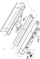
FIG. 3 is an exploded view of the slide rail assembly according to an embodiment of the present invention; -
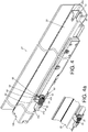
FIG. 4 is a diagram showing the slide rail assembly according to an embodiment of the present invention; -
FIG. 4a is a diagram showing another fixing frame of an adjusting device according to an embodiment of the present invention; -
FIG. 5 is a diagram showing the adjusting device according to an embodiment of the present invention; -
FIG. 6 is a cross-sectional view of the adjusting device according to an embodiment of the present invention; -
FIG. 7 is a diagram showing an adjusting member of the adjusting device being adjusted to drive a working member to move to a first position according to an embodiment of the present invention; -
FIG. 8 is a cross-sectional view of the adjusting member of the adjusting device being adjusted to drive the working member to move to the first position according to an embodiment of the present invention; -
FIG. 9 is a diagram showing the adjusting member of the adjusting device being adjusted to drive the working member to move to a second position according to an embodiment of the present invention; -
FIG. 10 is a cross-sectional view of the adjusting member of the adjusting device being adjusted to drive the working member to move to the second position according to an embodiment of the present invention; -
FIG. 11 is a diagram showing a second rail of the slide rail assembly of the furniture system being retracted to be located at an initial longitudinal position according to an embodiment of the present invention; -
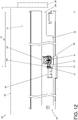
FIG. 12 is a diagram showing the second rail of the slide rail assembly of the furniture system being retracted to be located at a first longitudinal position according to an embodiment of the present invention; and -
FIG. 13 is a diagram showing the second rail of the slide rail assembly of the furniture system being retracted to be located at a second longitudinal position according to an embodiment of the present invention. - As shown in
FIG. 1 , afurniture system 20 of the present invention comprises afirst furniture part 22 and asecond furniture part 24. In the present embodiment, thefirst furniture part 22 is a cabinet, and thesecond furniture part 24 is a drawer.FIG. 1 shows that thefurniture system 20 comprises three drawers, but the quantity of the drawer is not limited in the present invention. - As shown in
FIG. 2 , thefurniture system 20 further comprises aslide rail assembly 21 having afirst rail 26 and asecond rail 28 longitudinally movable relative to thefirst rail 26. Preferably, theslide rail assembly 21 further comprises athird rail 30 movably mounted between thefirst rail 26 and thesecond rail 28 for extending a longitudinal traveling distance of thesecond rail 28 relative to thefirst rail 26. Wherein, thesecond furniture part 24 comprises abottom wall 32, aside wall 34, afront panel 36 and arear wall 38 for defining a drawer space. Wherein, thesecond rail 28 is configured to carry thesecond furniture part 24. In the present embodiment, theside wall 34 of thesecond furniture part 24 can be mounted to thesecond rail 28 in advance, and thefront panel 36 of thesecond furniture part 24 is detachably fixed to a front end part of theside wall 34. On the other hand, thefirst rail 26 is fixed to thefirst furniture part 22. According to such arrangement, thesecond furniture part 24 is movable relative to the first rail 26 (or the first furniture part 22) through thesecond rail 28. Such configuration is well known to those skilled in the art, for simplification, no further illustration is provided. - As shown in
FIG. 3 andFIG. 4 , theslide rail assembly 21 further comprises a blockingstructure 40 arranged on one of the first rail 26 (fixed member) and the second rail 28 (movable member) . In the present embodiment, the blockingstructure 40 is arranged on thefirst rail 26, but the present invention is not limited thereto. When the blockingstructure 40 is configured to be arranged on the fixed member of thefurniture system 20, the blockingstructure 40 can be arranged on one of thefirst rail 26 and thefirst furniture part 22. Preferably, the blockingstructure 40 is fixed to thefirst rail 26, and the blockingstructure 40 comprises abase 42 and a blockingmember 44. Thebase 42 has a connectingpart 42a, avertical part 42b, afirst bending part 42c and asecond bending part 42d. Wherein, the connectingpart 42a is fixedly connected to a bottom part of thefirst rail 26 and laterally extended from the bottom part of thefirst rail 26. Thevertical part 42b is substantially perpendicularly connected to the connectingpart 42a. Thefirst bending part 42c is connected between thevertical part 42b and thesecond bending part 42d. Wherein, a room 46 is defined by thevertical part 42b, thefirst bending part 42c and thesecond bending part 42d; and the blockingmember 44 is accommodated in the room 46. In the present embodiment, the blockingmember 44 is fixed to thebase 42 by engaging, and the blockingmember 44 is partially exposed outside the room 46. - Furthermore, the
slide rail assembly 21 further comprises an adjustingdevice 48 arranged on the other one of the first rail 26 (fixed member) and the second rail 28 (movable member) . In the present embodiment, the adjustingdevice 48 is arranged on a lateral side of thesecond rail 28 between afront part 28a and arear part 28b of thesecond rail 28, but the present invention is not limited thereto. When the adjustingdevice 48 is configured to be arranged on the movable member of thefurniture system 40, the adjustingdevice 48 can be arranged one of thesecond rail 28 and thesecond furniture part 24. The adjustingdevice 48 comprises an adjustingmember 50, a workingmember 52 and a fixingframe 54. - As shown in
FIG. 4 ,FIG. 5 and FIG. 6 , the fixingframe 54 comprises afirst wall 56 and asecond wall 58. Preferably, amiddle wall 60 is arranged between thefirst wall 56 and thesecond wall 58. Thefirst wall 56 and thesecond wall 58 are substantially perpendicularly connected to themiddle wall 60. Wherein, themiddle wall 60 is fixed to thesecond rail 28. For example, themiddle wall 60 can be fixed to thesecond rail 28 by screwing, riveting, engaging or welding (please refer toFIG. 4 ). On the other hand, when the adjustingdevice 48 is configured to be arranged on the fixed member of thefurniture system 20, themiddle wall 60 can be fixed to thefirst rail 26 or thefirst furniture part 22. As shown inFIG. 4a , in other embodiments, thefirst wall 56 and thesecond wall 58 of the fixing frame can be integrated with thesecond rail 28 and arranged on the lateral side of thesecond rail 28. Therefore, the present invention is not limited thereto. On the other hand, when the adjustingdevice 48 is configured to be arranged on the fixed member of thefurniture system 20, thefirst wall 56 and thesecond wall 58 of the fixingframe 54 can be integrated with thefirst rail 26 or thefirst furniture part 22. - As shown in
FIG. 5 and FIG. 6 , a space S is defined between thefirst wall 56 and thesecond wall 58 of the fixingframe 54. The adjustingmember 50 is accommodated in the space S. The adjustingmember 50 has a first side L1 and a second side L2 opposite to the first side L1, and the first side L1 and the second side L2 respectively correspond to thefirst wall 56 and thesecond wall 58, such that the adjustingmember 50 can be limited between thefirst wall 56 and thesecond wall 58. The first side L1 has ashaft part 62 pivoted to thefirst wall 56. - The working
member 52 comprises a screwingpart 52a, acontact part 52b and amiddle part 52c. Themiddle part 52c is connected between the screwingpart 52a and thecontact part 52b. Themiddle part 52c and the screwingpart 52a of the workingmember 52 are configured to pass through a hole H of thesecond wall 58 and the second side L2 of the adjustingmember 50 to be inserted into the adjustingmember 50. The screwingpart 52a is screwed to acorresponding thread part 50a of the adjustingmember 50. Wherein, thecontact part 52b of the workingmember 52 is located outside the space S of the fixingframe 54. Therefore, the adjustingmember 50 and the workingmember 52 are screwed to each other. Wherein, the workingmember 52 is located at an initial position P0 before the adjustingmember 50 is rotated. - As shown in
FIG. 7 and FIG. 8 , the adjustingdevice 48 is configured to convert a rotational movement of the adjustingmember 50 into a linear movement of the workingmember 52 relative to the fixingframe 54 along a linear direction X. For example, when the adjustingmember 50 is rotated along a first rotational direction R1, the workingmember 52 is linearly moved relative to the fixingframe 54 along a first direction D1 to a first position P1 in response to the rotation of the adjustingmember 50. Moreover, the hole H of thesecond wall 58 allows themiddle part 52c of the workingmember 52 to penetrate through. In the present embodiment, a contour of themiddle part 52c is substantially identical to a shape of the hole H. Preferably, the hole H is a non-circular hole. In other words, the hole H and themiddle part 52c have non-circular contours corresponding to each other. - On the other hand, as shown in
FIG. 9 and FIG. 10 , when the adjustingmember 50 is rotated along a second rotational direction R2, the workingmember 52 is linearly moved relative to the fixingframe 54 along a second direction D2 to a second position P2 in response to the rotation of the adjustingmember 50. Wherein, the second rotational direction R2 is opposite to the first rotational direction R1, and the second direction D2 is opposite to the first direction D1. - As shown in
FIG. 11 , the adjustingmember 50 has not been rotated and the workingmember 52 is located at the initial position P0. In such state, when the second rail 28 (or the second furniture part 24) is retracted (such as completely retracted) relative to the first rail 26 (or the first furniture part 22), the workingmember 52 at the initial position P0 is configured to abut against the blockingstructure 40. For example, thecontact part 52b of the workingmember 52 abuts against the blockingmember 44 of the blockingstructure 40, such that thesecond rail 28 is located at an initial longitudinal position Y0 relative to thefirst rail 26. Meanwhile, an initial distance K0 is defined between thefront part 28a of thesecond rail 28 and the blockingstructure 40. On the other hand, an initial longitudinal distance Z0 is defined between thefront panel 36 of thesecond furniture part 24 and the blockingstructure 40. - As shown in
FIG. 12 , the adjustingmember 50 can be rotated along the first rotational direction R1, to drive the workingmember 52 to move to the first position P1. In such state, when the second rail 28 (or the second furniture part 24) is retracted (such as completely retracted) relative to the first rail 26 (or the first furniture part 22), the workingmember 52 at the first position P1 is configured to abut against the blockingstructure 40. For example, thecontact part 52b of the workingmember 52 abuts against the blockingmember 44 of the blockingstructure 40, such that thesecond rail 28 is located at a first longitudinal position Y1 relative to thefirst rail 26. Meanwhile, a first distance K1 is defined between thefront part 28a of thesecond rail 28 and the blockingstructure 40. On the other hand, a first longitudinal distance Z1 is defined between thefront panel 36 of thesecond furniture part 24 and the blockingstructure 40. - As shown in
FIG. 13 , the adjustingmember 50 can be rotated along the second rotational direction R2, to drive the workingmember 52 to move to the second position P2. In such state, when the second rail 28 (or the second furniture part 24) is retracted (such as completely retracted) relative to the first rail 26 (or the first furniture part 22), the workingmember 52 at the second position P2 is configured to abut against the blockingstructure 40. For example, thecontact part 52b of the workingmember 52 abuts against the blockingmember 44 of the blockingstructure 40, such that thesecond rail 28 is located at a second longitudinal position Y2 relative to thefirst rail 26. Meanwhile, a second distance K2 is defined between thefront part 28a of thesecond rail 28 and the blockingstructure 40. On the other hand, a second longitudinal distance Z2 is defined between thefront panel 36 of thesecond furniture part 24 and the blockingstructure 40. Wherein, the second longitudinal position Y2 is different from the first longitudinal position Y1, the second distance K2 is different from the first distance K1, and the second longitudinal distance Z2 is different from the first longitudinal distance Z1. - Therefore, the furniture system and the slide rail assembly of the present invention are characterized in that:
- 1. Through adjusting the adjusting
member 50, the position of the workingmember 52 along the linear direction X can be changed (the linear direction X is substantially identical to a longitudinal direction of thefirst rail 26 or thesecond rail 28, or a moving direction of thesecond rail 28 relative to the first rail 26), and the workingmember 52 is configured to abut against the blockingstructure 40, such that thesecond rail 28 can be located at different longitudinal positions relative to thefirst rail 26 when the second rail 28 (or the second furniture part 24) is retracted (such as completely retracted) relative to the first rail 26 (or the first furniture part 22). As such, requirement of matching longitudinal depths (or lengths) or mounting tolerances for thefirst furniture part 22 and thesecond furniture part 24 can be satisfied. - 2. Through arranging the adjusting
device 48 and the blockingstructure 40 respectively on the movable member and the fixed member of the furniture system, the movable member (such as thesecond rail 28 or the second furniture part 24) can be located at different longitudinal positions relative to the fixed member (such as thefirst rail 26 or the first furniture part 22) when the movable member is retracted. Therefore, structural arrangement of the present invention is simpler than that of the prior art, in order to meet specific operation requirements in the market.
Claims (15)
- A slide rail assembly (21), comprising:a first rail (26);a second rail (28) longitudinally movable relative to the first rail (26) ;a blocking structure (40) arranged on one of the first rail (26) and the second rail (28); andan adjusting device (48) arranged on the other one of the first rail (26) and the second rail (28), the adjusting device (48) comprising an adjusting member (50), a working member (52) and a fixing frame (54);wherein the working member (52) is configured to abut against the blocking structure (40), the adjusting member (50) is configured to rotate to drive the working member (52) to move linearly relative to the fixing frame (54), in order to adjust a position of the second rail (28) along a longitudinal direction of the first rail (26) when the second rail (28) is retracted relative to the first rail (26) .
- The slide rail assembly of claim 1, characterized in that the blocking structure (40) is fixed to one of the first rail (26) and the second rail (28).
- The slide rail assembly of claim 1 or 2, characterized in that the fixing frame (54) comprises a first wall (56) and a second wall (58), a space is defined between the first wall (56) and the second wall (58), the adjusting member (50) is accommodated in the space, the adjusting member (50) has a first side and a second side opposite to the first side, the first side has a shaft part (62) connected to the first wall (56), a screwing part (52a) of the working member (52) is screwed to the adjusting member (50) from the second side, a contact part (52b) of the working member (52) is located outside the space, and the working member (52) is configured to abut against the blocking structure (40) through the contact part (52b).
- The slide rail assembly of claim 3, characterized in that the working member (52) further comprises a middle part (52c) connected between the screwing part (52a) and the contact part (52b), and the second wall (58) has a hole allowing the middle part (52c) to penetrate through; wherein the hole and the middle part (52c) have non-circular contours corresponding to each other.
- The slide rail assembly of claim 2, characterized in that the blocking structure (40) comprises a base (42) having a room (46) and a blocking member (44) accommodated in the room (46), the blocking member (44) is configured to abut against the working member (52).
- The slide rail assembly of any of claims 1-5, further characterized by a third rail (30) movably mounted between the first rail (26) and second rail (28) for extending a traveling distance of the second rail (28) relative to the first rail (26) .
- A slide rail assembly (21), comprising:a first rail (26);a second rail (28) longitudinally movable relative to the first rail (26), the second rail (28) having a front part (28a) and a rear part (28b);a blocking structure (40) arranged on the first rail (26); andan adjusting device (48) arranged on the second rail (28), the adjusting device (48) comprising a working member (52) and an adjusting member (50), wherein the working member (52) and the adjusting member (50) are screwed to each other;wherein when the second rail (28) is retracted relative to the first rail (26) and the working member (52) is adjusted by the adjusting member (50) to be located at a first position to abut against the blocking structure (40), a first distance is defined between the front part (28a) of the second rail (28) and the blocking structure (40) ;wherein when the second rail (28) is retracted relative to the first rail (26) and the working member (52) is adjusted by the adjusting member (50) to be located at a second position to abut against the blocking structure (40), a second distance is defined between the front part (28a) of the second rail (28) and the blocking structure (40), the second distance is different from the first distance.
- The slide rail assembly of claim 7, characterized in that the blocking structure (40) is fixed to the first rail (26).
- The slide rail assembly of claim 7 or 8, characterized in that the adjusting device (48) further comprises a fixing frame (54) fixed to the second rail (28), the fixing frame (54) comprises a first wall (56) and a second wall (58), a space is defined between the first wall (56) and the second wall (58), the adjusting member (50) is accommodated in the space, the adjusting member (50) has a first side and a second side opposite to the first side, the first side has a shaft part (62) connected to the first wall (56), a screwing part (52a) of the working member (52) is screwed to the adjusting member (50) from the second side, a contact part (52b) of the working member (52) is located outside the space, and the working member (52) is configured to abut against the blocking structure (40) through the contact part (52b).
- The slide rail assembly of claim 9, characterized in that the working member (52) further comprises a middle part (52c) connected between the screwing part (52a) and the contact part (52b), and the second wall (58) has a hole allowing the middle part (52c) to penetrate through; wherein the hole and the middle part (52c) have non-circular contours corresponding to each other.
- The slide rail assembly of any of claims 7-10, characterized in that the blocking structure (40) comprises a base (42) having a room (46) and a blocking member (44) accommodated in the room (46), the blocking member (44) is configured to abut against the working member (52).
- The slide rail assembly of claim 11, characterized in that the blocking member (44) is fixed to the base (42).
- A furniture system (20), comprising:a first furniture part (22) and a second furniture part (24) ;a first rail (26) fixed to the first furniture part (22);a second rail (28) configured to carry the second furniture part (24), the second rail (28) being longitudinally movable relative to the first rail (26);a blocking structure (40) arranged on one of the first rail (26) and the first furniture part (22); andan adjusting device (48) arranged on one of the second rail (28) and the second furniture part (24), the adjusting device (48) comprising a working member (52) and an adjusting member (50), wherein the working member (52) and the adjusting member (50) are screwed to each other;wherein when the second rail (28) is retracted relative to the first rail (26) and the working member (52) is adjusted by the adjusting member (50) to be located at a first position to abut against the blocking structure (40), a first longitudinal distance is defined between a front panel (36) of the second furniture part (24) and the blocking structure (40);wherein when the second rail (28) is retracted relative to the first rail (26) and the working member (52) is adjusted by the adjusting member (50) to be located at a second position to abut against the blocking structure (40), a second longitudinal distance is defined between the front panel (36) of the second furniture part (24) and the blocking structure (40), the second longitudinal distance is different from the first longitudinal distance.
- The furniture system of claim 13, characterized in that the adjusting device (48) further comprises a fixing frame (54) fixed to one of the second rail (28) and the second furniture part (24), the fixing frame (54) comprises a first wall (56) and a second wall (58), a space is defined between the first wall (56) and the second wall (58), the adjusting member (50) is accommodated in the space, the adjusting member (50) has a first side and a second side, the first side has a shaft part (62) connected to the first wall (56), a screwing part (52a) of the working member (52) is screwed to the adjusting member (50) from the second side, a contact part (52b) of the working member (52) is located outside the space, and the working member (52) is configured to abut against the blocking structure (40) through the contact part (52b) .
- The furniture system of claim 14, characterized in that the working member (52) further comprises a middle part (52c) connected between the screwing part (52a) and the contact part (52b), and the second wall (58) has a hole allowing the middle part (52c) to penetrate through; wherein the hole and the middle part (52c) have non-circular contours corresponding to each other.
Applications Claiming Priority (1)
| Application Number | Priority Date | Filing Date | Title |
|---|---|---|---|
| TW107102142A TW201932049A (en) | 2018-01-18 | 2018-01-18 | Furniture and slide rail assembly thereof |
Publications (2)
| Publication Number | Publication Date |
|---|---|
| EP3513681A1 true EP3513681A1 (en) | 2019-07-24 |
| EP3513681B1 EP3513681B1 (en) | 2019-11-20 |
Family
ID=62904335
Family Applications (1)
| Application Number | Title | Priority Date | Filing Date |
|---|---|---|---|
| EP18182412.9A Active EP3513681B1 (en) | 2018-01-18 | 2018-07-09 | Furniture system and slide rail assembly thereof |
Country Status (4)
| Country | Link |
|---|---|
| US (1) | US10568425B2 (en) |
| EP (1) | EP3513681B1 (en) |
| JP (1) | JP6691940B2 (en) |
| TW (1) | TW201932049A (en) |
Cited By (2)
| Publication number | Priority date | Publication date | Assignee | Title |
|---|---|---|---|---|
| CN111513494A (en) * | 2019-11-15 | 2020-08-11 | 广东金思达家居配件有限公司 | Anti-drop's slide rail buffer |
| WO2021222958A1 (en) * | 2020-05-07 | 2021-11-11 | Julius Blum Gmbh | Pull-out guide for a movable furniture part |
Families Citing this family (6)
| Publication number | Priority date | Publication date | Assignee | Title |
|---|---|---|---|---|
| USD906786S1 (en) * | 2017-12-22 | 2021-01-05 | Julius Blum Gmbh | Drawer part |
| CN110063597A (en) * | 2018-01-24 | 2019-07-30 | 川湖科技股份有限公司 | Furniture and its sliding rail assembly |
| AT521333B1 (en) * | 2018-06-05 | 2024-02-15 | Blum Gmbh Julius | Drawer pull-out guide |
| TWI670031B (en) * | 2018-09-27 | 2019-09-01 | 川湖科技股份有限公司 | Slide rail mechanism |
| CN112273904A (en) * | 2020-10-28 | 2021-01-29 | 广东库博精密科技有限公司 | Multifunctional adjustable guide rail |
| KR102234170B1 (en) * | 2020-12-01 | 2021-03-31 | 베스띠아 주식회사 | Drawer function storage furniture products equipped with modular for adjusting the side spacing of the drawer |
Citations (3)
| Publication number | Priority date | Publication date | Assignee | Title |
|---|---|---|---|---|
| DE20321444U1 (en) * | 2003-06-05 | 2007-05-24 | Grass Gmbh | Drawer rail system comprises rail attached to drawer and rail attached to carcass, functional unit, containing e.g. spring-loaded latches assisting fitting of drawer, being mounted on front of drawer rail and having similar cross-section |
| DE202010013193U1 (en) * | 2010-12-22 | 2012-03-26 | Paul Hettich Gmbh & Co. Kg | Opening and closing device for movable furniture parts and ejection device |
| US9179771B2 (en) | 2011-01-05 | 2015-11-10 | Julius Blum Gmbh | Coupling device for drawers |
Family Cites Families (12)
| Publication number | Priority date | Publication date | Assignee | Title |
|---|---|---|---|---|
| DE3641325A1 (en) * | 1986-12-03 | 1988-06-16 | Lautenschlaeger Kg Karl | DISTANCE PIECE FOR DRAWER EXTENSION GUIDES |
| US6945618B2 (en) * | 2003-06-02 | 2005-09-20 | Accuride International Inc. | Drawer slide adjustment mechanism |
| US20090212679A1 (en) * | 2008-02-23 | 2009-08-27 | Gus Frousiakis | Undermount slide drawer adjustment and securing apparatus |
| JP3159129U (en) | 2009-12-10 | 2010-05-13 | 川湖科技股▲分▼有限公司 | Auxiliary positioning device for slide rail construction |
| AT509416B1 (en) * | 2010-02-03 | 2012-05-15 | Blum Gmbh Julius | EXTRACTION GUIDE FOR A DRAWER |
| US8979223B2 (en) | 2012-12-12 | 2015-03-17 | Nan Juen International Co., Ltd. | Adjustable coupling device for connection between sliding rail assembly and a sliding box |
| DE102013104829A1 (en) | 2013-05-10 | 2014-11-13 | Paul Hettich Gmbh & Co. Kg | pull-out guide |
| DE102014104136A1 (en) * | 2014-03-25 | 2015-10-01 | Paul Hettich Gmbh & Co. Kg | Pull-out guide for a drawer and method for attaching a drawer to a drawer slide |
| US8854769B1 (en) | 2014-04-07 | 2014-10-07 | King Slide Works Co., Ltd. | Slide rail system and connecting device used for slide rail assembly |
| AT515690B1 (en) * | 2014-06-23 | 2015-11-15 | Fulterer Gmbh | pull-out |
| DE102015106854A1 (en) * | 2015-05-04 | 2016-11-10 | Paul Hettich Gmbh & Co. Kg | Device and method for fixing a pushing element |
| DE202015107020U1 (en) * | 2015-12-22 | 2017-03-24 | Grass Gmbh | Adjustment device, guide unit and furniture |
-
2018
- 2018-01-18 TW TW107102142A patent/TW201932049A/en unknown
- 2018-06-08 US US16/003,172 patent/US10568425B2/en active Active
- 2018-07-09 EP EP18182412.9A patent/EP3513681B1/en active Active
- 2018-07-31 JP JP2018143079A patent/JP6691940B2/en active Active
Patent Citations (3)
| Publication number | Priority date | Publication date | Assignee | Title |
|---|---|---|---|---|
| DE20321444U1 (en) * | 2003-06-05 | 2007-05-24 | Grass Gmbh | Drawer rail system comprises rail attached to drawer and rail attached to carcass, functional unit, containing e.g. spring-loaded latches assisting fitting of drawer, being mounted on front of drawer rail and having similar cross-section |
| DE202010013193U1 (en) * | 2010-12-22 | 2012-03-26 | Paul Hettich Gmbh & Co. Kg | Opening and closing device for movable furniture parts and ejection device |
| US9179771B2 (en) | 2011-01-05 | 2015-11-10 | Julius Blum Gmbh | Coupling device for drawers |
Cited By (6)
| Publication number | Priority date | Publication date | Assignee | Title |
|---|---|---|---|---|
| CN111513494A (en) * | 2019-11-15 | 2020-08-11 | 广东金思达家居配件有限公司 | Anti-drop's slide rail buffer |
| WO2021222958A1 (en) * | 2020-05-07 | 2021-11-11 | Julius Blum Gmbh | Pull-out guide for a movable furniture part |
| AT523789A1 (en) * | 2020-05-07 | 2021-11-15 | Blum Gmbh Julius | Pull-out guide for a movable furniture part |
| EP4245187A3 (en) * | 2020-05-07 | 2023-12-13 | Julius Blum GmbH | Pull-out guide for a movable furniture part |
| AT523789B1 (en) * | 2020-05-07 | 2024-04-15 | Blum Gmbh Julius | Pull-out guide for a movable furniture part |
| US12096852B2 (en) | 2020-05-07 | 2024-09-24 | Julius Blum Gmbh | Pull-out guide for a movable furniture part |
Also Published As
| Publication number | Publication date |
|---|---|
| US20190216219A1 (en) | 2019-07-18 |
| US10568425B2 (en) | 2020-02-25 |
| TW201932049A (en) | 2019-08-16 |
| JP6691940B2 (en) | 2020-05-13 |
| JP2019122748A (en) | 2019-07-25 |
| EP3513681B1 (en) | 2019-11-20 |
Similar Documents
| Publication | Publication Date | Title |
|---|---|---|
| EP3513681B1 (en) | Furniture system and slide rail assembly thereof | |
| EP3398481B1 (en) | Slide rail assembly | |
| EP3154320B1 (en) | Slide rail assembly and bracket device thereof | |
| EP2551433A2 (en) | Door opening/closing device unit and method for mounting the same | |
| EP3782513B1 (en) | Slide rail assembly allowing lateral float | |
| EP4321053B1 (en) | Slide rail assembly | |
| EP3530147B1 (en) | Slide rail assembly | |
| EP3567994A1 (en) | Slide rail assembly and slide rail kit thereof | |
| EP3614816B1 (en) | Coupling assembly and cable management device thereof | |
| EP3270669A1 (en) | Bracket device | |
| US20150230605A1 (en) | Stopper mechanism of slide rail | |
| TWI693043B (en) | Adjustment mechanism | |
| US9750346B2 (en) | Drawer slide assembly | |
| EP3085270B1 (en) | Vertical and horizontal adjusting device for drawers | |
| EP3136694B1 (en) | Housing mounting mechanism for portable electronic device | |
| US10470568B1 (en) | Adjustment mechanism for slide rail assembly | |
| EP3058847B1 (en) | Slide rail assembly | |
| CN117694679A (en) | Furniture and slide rail assembly thereof | |
| EP4427635A1 (en) | Furniture system and furniture assembly thereof | |
| CN110786659B (en) | Adjustment agency | |
| EP3449767A1 (en) | Slide rail mechanism and adjusting assembly for slide rail | |
| CN110200423B (en) | Slide rail assembly for furniture | |
| CN110960011B (en) | Slide rail mechanism | |
| JP2018158005A (en) | Slide panel and optical panel with slide rail | |
| CN118844759A (en) | A connection device for adjusting the position of a drawer |
Legal Events
| Date | Code | Title | Description |
|---|---|---|---|
| PUAI | Public reference made under article 153(3) epc to a published international application that has entered the european phase |
Free format text: ORIGINAL CODE: 0009012 |
|
| STAA | Information on the status of an ep patent application or granted ep patent |
Free format text: STATUS: REQUEST FOR EXAMINATION WAS MADE |
|
| 17P | Request for examination filed |
Effective date: 20190221 |
|
| AK | Designated contracting states |
Kind code of ref document: A1 Designated state(s): AL AT BE BG CH CY CZ DE DK EE ES FI FR GB GR HR HU IE IS IT LI LT LU LV MC MK MT NL NO PL PT RO RS SE SI SK SM TR |
|
| AX | Request for extension of the european patent |
Extension state: BA ME |
|
| GRAP | Despatch of communication of intention to grant a patent |
Free format text: ORIGINAL CODE: EPIDOSNIGR1 |
|
| STAA | Information on the status of an ep patent application or granted ep patent |
Free format text: STATUS: GRANT OF PATENT IS INTENDED |
|
| INTG | Intention to grant announced |
Effective date: 20190805 |
|
| GRAS | Grant fee paid |
Free format text: ORIGINAL CODE: EPIDOSNIGR3 |
|
| GRAA | (expected) grant |
Free format text: ORIGINAL CODE: 0009210 |
|
| STAA | Information on the status of an ep patent application or granted ep patent |
Free format text: STATUS: THE PATENT HAS BEEN GRANTED |
|
| AK | Designated contracting states |
Kind code of ref document: B1 Designated state(s): AL AT BE BG CH CY CZ DE DK EE ES FI FR GB GR HR HU IE IS IT LI LT LU LV MC MK MT NL NO PL PT RO RS SE SI SK SM TR |
|
| REG | Reference to a national code |
Ref country code: GB Ref legal event code: FG4D |
|
| REG | Reference to a national code |
Ref country code: CH Ref legal event code: EP |
|
| REG | Reference to a national code |
Ref country code: IE Ref legal event code: FG4D |
|
| REG | Reference to a national code |
Ref country code: DE Ref legal event code: R096 Ref document number: 602018001267 Country of ref document: DE |
|
| REG | Reference to a national code |
Ref country code: AT Ref legal event code: REF Ref document number: 1203172 Country of ref document: AT Kind code of ref document: T Effective date: 20191215 |
|
| REG | Reference to a national code |
Ref country code: NL Ref legal event code: MP Effective date: 20191120 |
|
| REG | Reference to a national code |
Ref country code: LT Ref legal event code: MG4D |
|
| PG25 | Lapsed in a contracting state [announced via postgrant information from national office to epo] |
Ref country code: LV Free format text: LAPSE BECAUSE OF FAILURE TO SUBMIT A TRANSLATION OF THE DESCRIPTION OR TO PAY THE FEE WITHIN THE PRESCRIBED TIME-LIMIT Effective date: 20191120 Ref country code: BG Free format text: LAPSE BECAUSE OF FAILURE TO SUBMIT A TRANSLATION OF THE DESCRIPTION OR TO PAY THE FEE WITHIN THE PRESCRIBED TIME-LIMIT Effective date: 20200220 Ref country code: FI Free format text: LAPSE BECAUSE OF FAILURE TO SUBMIT A TRANSLATION OF THE DESCRIPTION OR TO PAY THE FEE WITHIN THE PRESCRIBED TIME-LIMIT Effective date: 20191120 Ref country code: SE Free format text: LAPSE BECAUSE OF FAILURE TO SUBMIT A TRANSLATION OF THE DESCRIPTION OR TO PAY THE FEE WITHIN THE PRESCRIBED TIME-LIMIT Effective date: 20191120 Ref country code: NO Free format text: LAPSE BECAUSE OF FAILURE TO SUBMIT A TRANSLATION OF THE DESCRIPTION OR TO PAY THE FEE WITHIN THE PRESCRIBED TIME-LIMIT Effective date: 20200220 Ref country code: LT Free format text: LAPSE BECAUSE OF FAILURE TO SUBMIT A TRANSLATION OF THE DESCRIPTION OR TO PAY THE FEE WITHIN THE PRESCRIBED TIME-LIMIT Effective date: 20191120 Ref country code: GR Free format text: LAPSE BECAUSE OF FAILURE TO SUBMIT A TRANSLATION OF THE DESCRIPTION OR TO PAY THE FEE WITHIN THE PRESCRIBED TIME-LIMIT Effective date: 20200221 Ref country code: NL Free format text: LAPSE BECAUSE OF FAILURE TO SUBMIT A TRANSLATION OF THE DESCRIPTION OR TO PAY THE FEE WITHIN THE PRESCRIBED TIME-LIMIT Effective date: 20191120 |
|
| PG25 | Lapsed in a contracting state [announced via postgrant information from national office to epo] |
Ref country code: IS Free format text: LAPSE BECAUSE OF FAILURE TO SUBMIT A TRANSLATION OF THE DESCRIPTION OR TO PAY THE FEE WITHIN THE PRESCRIBED TIME-LIMIT Effective date: 20200320 Ref country code: RS Free format text: LAPSE BECAUSE OF FAILURE TO SUBMIT A TRANSLATION OF THE DESCRIPTION OR TO PAY THE FEE WITHIN THE PRESCRIBED TIME-LIMIT Effective date: 20191120 Ref country code: HR Free format text: LAPSE BECAUSE OF FAILURE TO SUBMIT A TRANSLATION OF THE DESCRIPTION OR TO PAY THE FEE WITHIN THE PRESCRIBED TIME-LIMIT Effective date: 20191120 |
|
| PG25 | Lapsed in a contracting state [announced via postgrant information from national office to epo] |
Ref country code: AL Free format text: LAPSE BECAUSE OF FAILURE TO SUBMIT A TRANSLATION OF THE DESCRIPTION OR TO PAY THE FEE WITHIN THE PRESCRIBED TIME-LIMIT Effective date: 20191120 |
|
| PG25 | Lapsed in a contracting state [announced via postgrant information from national office to epo] |
Ref country code: CZ Free format text: LAPSE BECAUSE OF FAILURE TO SUBMIT A TRANSLATION OF THE DESCRIPTION OR TO PAY THE FEE WITHIN THE PRESCRIBED TIME-LIMIT Effective date: 20191120 Ref country code: DK Free format text: LAPSE BECAUSE OF FAILURE TO SUBMIT A TRANSLATION OF THE DESCRIPTION OR TO PAY THE FEE WITHIN THE PRESCRIBED TIME-LIMIT Effective date: 20191120 Ref country code: RO Free format text: LAPSE BECAUSE OF FAILURE TO SUBMIT A TRANSLATION OF THE DESCRIPTION OR TO PAY THE FEE WITHIN THE PRESCRIBED TIME-LIMIT Effective date: 20191120 Ref country code: EE Free format text: LAPSE BECAUSE OF FAILURE TO SUBMIT A TRANSLATION OF THE DESCRIPTION OR TO PAY THE FEE WITHIN THE PRESCRIBED TIME-LIMIT Effective date: 20191120 Ref country code: PT Free format text: LAPSE BECAUSE OF FAILURE TO SUBMIT A TRANSLATION OF THE DESCRIPTION OR TO PAY THE FEE WITHIN THE PRESCRIBED TIME-LIMIT Effective date: 20200412 Ref country code: ES Free format text: LAPSE BECAUSE OF FAILURE TO SUBMIT A TRANSLATION OF THE DESCRIPTION OR TO PAY THE FEE WITHIN THE PRESCRIBED TIME-LIMIT Effective date: 20191120 |
|
| REG | Reference to a national code |
Ref country code: AT Ref legal event code: MK05 Ref document number: 1203172 Country of ref document: AT Kind code of ref document: T Effective date: 20191120 |
|
| REG | Reference to a national code |
Ref country code: DE Ref legal event code: R097 Ref document number: 602018001267 Country of ref document: DE |
|
| PG25 | Lapsed in a contracting state [announced via postgrant information from national office to epo] |
Ref country code: SM Free format text: LAPSE BECAUSE OF FAILURE TO SUBMIT A TRANSLATION OF THE DESCRIPTION OR TO PAY THE FEE WITHIN THE PRESCRIBED TIME-LIMIT Effective date: 20191120 Ref country code: SK Free format text: LAPSE BECAUSE OF FAILURE TO SUBMIT A TRANSLATION OF THE DESCRIPTION OR TO PAY THE FEE WITHIN THE PRESCRIBED TIME-LIMIT Effective date: 20191120 |
|
| PLBE | No opposition filed within time limit |
Free format text: ORIGINAL CODE: 0009261 |
|
| STAA | Information on the status of an ep patent application or granted ep patent |
Free format text: STATUS: NO OPPOSITION FILED WITHIN TIME LIMIT |
|
| 26N | No opposition filed |
Effective date: 20200821 |
|
| PG25 | Lapsed in a contracting state [announced via postgrant information from national office to epo] |
Ref country code: AT Free format text: LAPSE BECAUSE OF FAILURE TO SUBMIT A TRANSLATION OF THE DESCRIPTION OR TO PAY THE FEE WITHIN THE PRESCRIBED TIME-LIMIT Effective date: 20191120 Ref country code: PL Free format text: LAPSE BECAUSE OF FAILURE TO SUBMIT A TRANSLATION OF THE DESCRIPTION OR TO PAY THE FEE WITHIN THE PRESCRIBED TIME-LIMIT Effective date: 20191120 |
|
| PG25 | Lapsed in a contracting state [announced via postgrant information from national office to epo] |
Ref country code: IT Free format text: LAPSE BECAUSE OF FAILURE TO SUBMIT A TRANSLATION OF THE DESCRIPTION OR TO PAY THE FEE WITHIN THE PRESCRIBED TIME-LIMIT Effective date: 20191120 |
|
| PG25 | Lapsed in a contracting state [announced via postgrant information from national office to epo] |
Ref country code: MC Free format text: LAPSE BECAUSE OF FAILURE TO SUBMIT A TRANSLATION OF THE DESCRIPTION OR TO PAY THE FEE WITHIN THE PRESCRIBED TIME-LIMIT Effective date: 20191120 |
|
| REG | Reference to a national code |
Ref country code: BE Ref legal event code: MM Effective date: 20200731 |
|
| PG25 | Lapsed in a contracting state [announced via postgrant information from national office to epo] |
Ref country code: FR Free format text: LAPSE BECAUSE OF NON-PAYMENT OF DUE FEES Effective date: 20200731 Ref country code: LU Free format text: LAPSE BECAUSE OF NON-PAYMENT OF DUE FEES Effective date: 20200709 |
|
| PG25 | Lapsed in a contracting state [announced via postgrant information from national office to epo] |
Ref country code: BE Free format text: LAPSE BECAUSE OF NON-PAYMENT OF DUE FEES Effective date: 20200731 |
|
| REG | Reference to a national code |
Ref country code: CH Ref legal event code: PL |
|
| PG25 | Lapsed in a contracting state [announced via postgrant information from national office to epo] |
Ref country code: LI Free format text: LAPSE BECAUSE OF NON-PAYMENT OF DUE FEES Effective date: 20210731 Ref country code: CH Free format text: LAPSE BECAUSE OF NON-PAYMENT OF DUE FEES Effective date: 20210731 |
|
| PG25 | Lapsed in a contracting state [announced via postgrant information from national office to epo] |
Ref country code: TR Free format text: LAPSE BECAUSE OF FAILURE TO SUBMIT A TRANSLATION OF THE DESCRIPTION OR TO PAY THE FEE WITHIN THE PRESCRIBED TIME-LIMIT Effective date: 20191120 Ref country code: MT Free format text: LAPSE BECAUSE OF FAILURE TO SUBMIT A TRANSLATION OF THE DESCRIPTION OR TO PAY THE FEE WITHIN THE PRESCRIBED TIME-LIMIT Effective date: 20191120 Ref country code: CY Free format text: LAPSE BECAUSE OF FAILURE TO SUBMIT A TRANSLATION OF THE DESCRIPTION OR TO PAY THE FEE WITHIN THE PRESCRIBED TIME-LIMIT Effective date: 20191120 |
|
| PG25 | Lapsed in a contracting state [announced via postgrant information from national office to epo] |
Ref country code: MK Free format text: LAPSE BECAUSE OF FAILURE TO SUBMIT A TRANSLATION OF THE DESCRIPTION OR TO PAY THE FEE WITHIN THE PRESCRIBED TIME-LIMIT Effective date: 20191120 |
|
| PG25 | Lapsed in a contracting state [announced via postgrant information from national office to epo] |
Ref country code: SI Free format text: LAPSE BECAUSE OF FAILURE TO SUBMIT A TRANSLATION OF THE DESCRIPTION OR TO PAY THE FEE WITHIN THE PRESCRIBED TIME-LIMIT Effective date: 20191120 |
|
| PGFP | Annual fee paid to national office [announced via postgrant information from national office to epo] |
Ref country code: GB Payment date: 20250508 Year of fee payment: 8 |
|
| PGFP | Annual fee paid to national office [announced via postgrant information from national office to epo] |
Ref country code: IE Payment date: 20250507 Year of fee payment: 8 |
|
| PGFP | Annual fee paid to national office [announced via postgrant information from national office to epo] |
Ref country code: DE Payment date: 20250512 Year of fee payment: 8 |